Monorail guidance systems - AHR International Ltd
Monorail guidance systems - AHR International Ltd
Monorail guidance systems - AHR International Ltd

You also want an ePaper? Increase the reach of your titles
YUMPU automatically turns print PDFs into web optimized ePapers that Google loves.
MONORAIL<br />
GUIDANCE SYSTEMS<br />
CORPORATE OFFICES<br />
308 SPRINGHILL FARM ROAD<br />
FORT MILL, SOUTH CAROLINA 29715<br />
TELEPHONE (803)548-8500<br />
FAX (803)548-8599<br />
DISTRIBUTOR CUSTOMER SERVICE<br />
TOLL FREE 800-523-6572<br />
FAX (803)548-8594<br />
LINEAR CUSTOMER SERVICE<br />
TOLL FREE 800-462-3399<br />
FAX (215)781-9830<br />
This product section has been excerpted from our full<br />
Product Reference Guide to reduce download time.<br />
Our complete Product Reference Guide is available in<br />
print and on CD-ROM. To receive the full version,<br />
please contact your nearest INA Sales Office listed on<br />
the last page of this file.
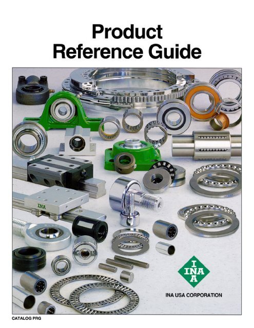
This publication was designed to serve as a quick reference<br />
to the standard product series offered by INA USA<br />
Corporation (INA) for its domestic market. The guide provides<br />
a current overview of INA products, including basic<br />
envelope dimensions and capacities, in one publication –<br />
it is not an engineering design guide intended to replace<br />
INA engineering catalogs. Consequently, the metric and<br />
inch conversions are listed to 3 decimal places for easy<br />
reference and rapid identification of correct replacement<br />
part(s), not 4 decimal places as necessary for quality<br />
control purposes.<br />
This publication can be used to narrow the choices between<br />
the many different INA product lines and series for<br />
new designs. Detailed engineering information for new<br />
designs can be found in our traditional catalogs or by<br />
contacting the INA Engineering Department.<br />
A significant portion of INA sales are special production<br />
sizes. The identification of those parts is sometimes difficult<br />
since a comprehensive listing is beyond the intent of<br />
this publication. Special part numbers take as many different<br />
forms as the series listed here, but the basic system<br />
is to use sequential numbers for each new design.<br />
Usually the prefix is F or FC but can include VH, INA or<br />
the bearing type such as NA. INA maintains a technical<br />
help desk to identify sizes not known or to match competitors’<br />
parts.<br />
The toll free 800 numbers listed will give you access to<br />
INA Customer Service representatives. These representatives<br />
can tap into INA Worldwide resources to provide<br />
the bearings you need.<br />
Storage Life<br />
Lubricants age naturally due to environmental influences.<br />
It is therefore the user’s responsibility to follow the directions<br />
given by the lubricant manufacturer.<br />
The greases used in INA rolling bearings have a mineral<br />
oil base and experience shows that they can be stored for<br />
up to 3 years without deteriorating providing the following<br />
important conditions are met.<br />
Closed storage room<br />
Temperature between 0C and 40C<br />
Relative atmospheric humidity 65% or less<br />
Security from chemical agents<br />
(vapors, gases, fluids)<br />
Sealed rolling bearings<br />
The frictional torque can be considerably higher after linger<br />
storage periods than in freshly greased bearings and<br />
the lubricity of the grease can also have deteriorated.<br />
INA bearings have many optional features available including:<br />
ISO series of bearings generally include the standard<br />
clearance options CN, C2, C3 and C4.<br />
ISO bearing series include PN, P6 and P5 precision<br />
classes.<br />
FOREWORD<br />
Corrotect plating is available for most bearing designs.<br />
Corrotect is a patented process for zinc–iron<br />
and zinc–iron–cobalt plating in a thin layer which can<br />
be applied to standard components. The protection<br />
exceeds stainless steel and the cost is half. Add<br />
suffix RR.<br />
All sealed bearings are supplied pregreased. In<br />
most cases the standard lubricant is Shell Alvania 2<br />
or equivalent. Other greases are available, some at<br />
extra cost.<br />
Unsealed bearings may not be greased when<br />
shipped.<br />
Speed limits as published, are based on oil lubrication<br />
for open bearings or grease lubrication for<br />
sealed bearings. The speed limits are calculated<br />
based on a nominal load and heat balance equation.<br />
Higher speeds may be allowed depending on the<br />
application.<br />
Dynamic capacities are published based on INA<br />
standard usage of ISO and ABMA formulas. New<br />
life theory threshold values are published in other<br />
INA publications.<br />
Life calculations and evaluations can be made from<br />
INA engineering based catalogs which are available<br />
from your INA Sales Representative.<br />
Other features are available based on current production<br />
volumes including heat stabilization of the<br />
rings, matched bearing sets, with oil holes and<br />
grooves, etc.<br />
ABMA American Bearing Manufacturers Association<br />
ASTM American Society Of Testing And Materials<br />
DIN Deutsches Institut für Normung e.V.<br />
ISO <strong>International</strong> Standards Organization<br />
Elges, Andrews and Corrotect are registered trademarks of<br />
INA USA Corporation.<br />
Permaglide is a registered trademark and a product of<br />
KOLBENSCHMIDT AG, Neckarsulm, also produced in<br />
Greensburg, Indiana, USA.<br />
All other products and company names are trademarks or registered<br />
trademarks of their respective companies.<br />
ALL RIGHTS RESERVED<br />
INA USA Corporation<br />
308 Springhill Farm Road<br />
Fort Mill, SC 29715<br />
Reproduction of this publication in whole or in part without the express<br />
written consent of INA USA Corporation is prohibited.<br />
Although every effort has been made to ensure the accuracy of the<br />
information contained in this catalog, INA shall not be liable for any<br />
omissions or errors. Purchasers should consult their own testing to<br />
determine the suitability of any product for a particular purpose. In no<br />
event shall INA be liable for any claims for damages based upon breach<br />
of warranty, breach of contract, negligence, strict liability in tort, or any<br />
other legal theory.<br />
INA USA Corporation reserves the right to make changes / revisions to<br />
specifications contained herein without notice.<br />
Copyright 1999, 2000 INA USA Corporation
Linear Recirculating Roller Bearing<br />
And Guideway Assemblies<br />
RUE..D, RUE..DL, RUE 65 L SERIES<br />
For details on part numbers, descriptive suffixes and various technical references, please refer to front of this section.<br />
For engineering or technical information contact your local sales representative or call Distributor Sales (800)523-6572 or Linear Sales (800)462-3399.<br />
Linear roller bearing<br />
and guideway<br />
assembly<br />
Grease Lubrication<br />
PART NUMBER<br />
444<br />
Linear roller bearing<br />
and guideway<br />
assembly<br />
Oil Lubrication<br />
PART NUMBER<br />
CARRIAGE 1 )<br />
PART NUMBER<br />
CARRIAGE<br />
MASS<br />
kg<br />
GUIDEWAY<br />
PART<br />
NUMBER<br />
GUIDEWAY<br />
MASS<br />
kg/m<br />
GUIDEWAY<br />
Closing<br />
Plugs 2 )<br />
COVERING<br />
STRIP<br />
RUE 35 D FE RUE 35 D OE RWU 35 D 2.0 TSX 35 D 5.9 KA 15 ADB 18 2960 48 100 120<br />
RUE 35 D L FE RUE 35 D L OE RWU 35 D L 2.7 TSX 35 D 5.9 KA 15 ADB 18 2960 48 100 143<br />
RUE 45 D FE RUE 45 D OE RWU 45 D 3.3 TSX 45 D 9.4 KA 20 ADB 23 2940 60 120 141<br />
RUE 45 D L FE RUE 45 D L OE RWU 45 D L 4.4 TSX 45 D 9.4 KA 20 ADB 23 2940 60 120 175<br />
RUE 55 D FE RUE 55 D OE RWU 55 D 5.6 TSX 55 D 13.3 KA 24 ADB 27 2520 70 140 170<br />
RUE D L FE RUE 55 D L OE RWU 55 D L 7.5 TSX 55 D 13.3 KA 24 ADB 27 2520 70 140 210<br />
RUE 65 D L FE RUE 65 D L OE RWU 65 D L 14.4 TSX 65 D 21.5 KA 26 ADB 29 2520 90 170 252.8<br />
1 )<br />
RUE..D FE has lubrication nipple to DIN 71 412-A M81.<br />
RUE..D OE has connector with union nut similar to DIN 3 871-A.<br />
RUE 25 available on request.<br />
RUE..U: Linear roller bearing and guideway assembly with guideway for fixing from below, available on request.<br />
Suffix FE for grease lubrication, suffix OE for oil lubrication.<br />
2 ) Closing plugs KA..TN are included with the delivery.<br />
3 ) Maximum length L of single-piece guideways, longer guideways are supplied as multi-piece guideways and are marked accordingly.<br />
4 ) Minimum covered length for sealing the lubrication connections.<br />
5 ) Dimensions C5 and C6 are dependent on the guideway length L.<br />
6 ) Position of the lubrication hole in the adjacent construction.<br />
7 ) Maximum diameter of the lubrication hole in the adjacent construction.<br />
8 ) Maximum length of fixing screw: H8 +3 mm.<br />
9 ) If there is a possibility of settling, the fixing screws should be secured against rotation.<br />
PART NUMBER K 1<br />
For screws to DIN 912-12.9<br />
DIAMETERS AND TIGHTENING TORQUES FOR THREADS AND SCREWS 9 )<br />
Nm<br />
max.<br />
K 2<br />
For screws to DIN 912-12.9<br />
Nm<br />
max.<br />
K3 Through holes for screws to<br />
DIN 912-12.9<br />
Nm<br />
max.<br />
L 3 )<br />
mm<br />
H<br />
mm<br />
A<br />
mm<br />
C 4 )<br />
mm<br />
K6 Through holes for screws to<br />
DIN 7 984-8.8<br />
Nm<br />
max.<br />
RUE 35 D M8 41 M10 41 M8 41 M8 24<br />
RUE 35 D L M8 41 M10 41 M8 41 M8 24<br />
RUE 45 D M12 140 M12 83 M10 83 M10 48<br />
RUE 45 D L M12 140 M12 83 M10 83 M10 48<br />
RUE 55 D M14 220 M14 140 M12 140 M12 83<br />
RUE 55 D L M14 220 M14 140 M12 140 M12 83<br />
RUE 65 L M16 340 M16 220 M14 220 M14 130
A<br />
Marking Locating face<br />
K2 K6 K2 H<br />
RUE..D<br />
A 1<br />
mm<br />
h<br />
H 8 H 3<br />
h 1<br />
Marking<br />
A 2<br />
mm<br />
a<br />
–0.005<br />
–0.035<br />
mm<br />
C 1<br />
mm<br />
C 2<br />
mm<br />
a A 1<br />
C 3<br />
mm<br />
C 4<br />
mm<br />
K 3<br />
H 5 H7 H6<br />
H 1<br />
<br />
<br />
<br />
<br />
<br />
Locating face<br />
<br />
<br />
RUE..D<br />
(View rotated through 90)<br />
C 5<br />
5 )<br />
min.<br />
C 5<br />
5 )<br />
max.<br />
C 5<br />
6 )<br />
min.<br />
C 5<br />
6 )<br />
max.<br />
C 6<br />
7 ) d 7<br />
1 )<br />
max.<br />
H1 mm<br />
mm<br />
mm<br />
mm<br />
mm<br />
mm<br />
mm<br />
<br />
Load directions<br />
<br />
<br />
<br />
<br />
H 3<br />
mm<br />
<br />
<br />
H 5<br />
mm<br />
<br />
<br />
<br />
<br />
<br />
<br />
H 6<br />
mm<br />
<br />
H 7<br />
mm<br />
<br />
<br />
H 8 8 )<br />
mm<br />
<br />
<br />
<br />
33 82 34 91.4 62 52 40 20 31 20 31 14.3 6 6.5 6.6 8 20 12 11.1 30 19<br />
33 82 34 114.4 62 52 40 20 31 20 31 25.8 6 6.5 6.6 8 20 12 11.1 30 19<br />
37.5 100 45 107.5 80 60 52.5 20 41 20 41 16.2 6 8.5 8.5 8 26 15 13.5 38 22<br />
37.5 100 45 141.7 80 60 52.5 20 41 20 41 33.3 6 8.5 8.5 8 26 15 13.5 38 22<br />
43.5 116 53 130.8 95 70 60 20 47 20 47 21.2 6 11 10 12 31 18 15.5 45 28<br />
43.5 116 53 170.5 95 70 60 20 47 20 47 41 6 11 10 12 31 18 15.5 45 28<br />
53.5 142 63 207.6 110 82 75 20 61 20 61 49 6 11 10.2 15 39.2 23 23 53.8 30.3<br />
LOAD CARRYING CAPACITY TABLE<br />
PART PART NUMBER BASIC LOAD RATINGS MOMENT RATINGS<br />
C<br />
C0 M0x M0y M0z kN<br />
kN<br />
Nm Nm<br />
Nm<br />
RUE 35 D 59 134 990 2140 1925<br />
RUE 35 D L 70 169 1255 3370 3035<br />
RUE 45 D 92 205 1805 3870 3485<br />
RUE 45 D L 115 275 2410 6770 6095<br />
RUE 55 D 135 305 3130 7035 6335<br />
RUE 55 D L 167 405 4120 12010 10815<br />
RUE 65 D L 270 640 7600 24000 21500<br />
<br />
<br />
<br />
<br />
h<br />
mm<br />
<br />
h 1<br />
mm<br />
445
Linear Recirculating Roller Bearing<br />
And Guideway Assemblies<br />
RUE..D H, RUE..D HL SERIES<br />
For details on part numbers, descriptive suffixes and various technical references, please refer to front of this section.<br />
For engineering or technical information contact your local sales representative or call Distributor Sales (800)523-6572 or Linear Sales (800)462-3399.<br />
Linear roller bearing<br />
and guideway<br />
assembly<br />
Grease Lubrication<br />
PART NUMBER<br />
446<br />
Linear roller bearing<br />
and guideway<br />
assembly<br />
Oil Lubrication<br />
PART NUMBER<br />
CARRIAGE 1 )<br />
PART NUMBER<br />
CARRIAGE<br />
MASS<br />
kg<br />
GUIDEWAY<br />
PART<br />
NUMBER<br />
GUIDEWAY<br />
MASS<br />
kg/m<br />
GUIDEWAY<br />
Closing<br />
Plugs 2 )<br />
COVERING<br />
STRIP<br />
RUE 35 D H FE RUE 35 D H OE RWU 35 D H 1.7 TSX 35 D 5.9 KA 15 ADB 18 2 960 55 70 120<br />
RUE 35 D HL FE RUE 35 D HL OE RWU 35 D HL 2.4 TSX 35 D 5.9 KA 15 ADB 18 2 960 55 70 143<br />
RUE 45 D H FE RUE 45 D H OE RWU 45 D H 3.1 TSX 45 D 9.4 KA 20 ADB 23 2 940 70 86 141<br />
RUE 45 D HL FE RUE 45 D HL OE RWU 45 D HL 4.0 TSX 45 D 9.4 KA 20 ADB 23 2 940 70 86 175<br />
RUE 55 D H FE RUE 55 D H OE RWU 55 D H 5.3 TSX 55 D 13.3 KA 24 ADB 24 2 520 80 100 170<br />
RUE 55 D HL FE RUE 55 D HL OE RWU 55 D HL 6.7 TSX 55 D 13.3 KA 24 ADB 24 2 520 80 100 210<br />
RUE 65 D HL FE RUE 65 D HL OE RWU 65 D HL 13.6 TSX 65 D 21.5 KA 26 ADB 26 2 520 100 126 252.8<br />
1 )<br />
RUE..D H FE has lubrication nipple to DIN 71 412-A M81.<br />
RUE..D H OE has connector with union nut similar to DIN 3 871-A.<br />
RUE..DU: Linear roller bearing and guideway assembly with guideway for fixing from below, available on request.<br />
Suffix FE for grease lubrication, suffix OE for oil lubrication.<br />
2 ) Closing plugs KA..TN are included with the delivery.<br />
3 ) Maximum length L of single-piece guideways, longer guideways are supplied as multi-piece guideways and are marked accordingly.<br />
4 ) Minimum covered length for sealing the lubrication connections.<br />
5 ) Dimensions C5 and C6 are dependent on the guideway length L.<br />
6 ) Position of the lubrication hole in the adjacent construction.<br />
7 ) Maximum diameter of the lubrication hole in the adjacent construction.<br />
8 ) If there is a possibility of settling, the fixing screws should be secured against rotation.<br />
DIAMETERS AND TIGHTENING TORQUES FOR THREADS AND SCREWS 8 )<br />
PART NUMBER K 1<br />
For screws to DIN 912-12.9<br />
L 3 )<br />
mm<br />
H<br />
mm<br />
K 2<br />
For screws to DIN 912-12.9<br />
Nm<br />
max.<br />
RUE 35 D H M8 41 M8 41<br />
RUE 35 D HL M8 41 M8 41<br />
RUE 45 D H M12 140 M10 83<br />
RUE 45 D HL M12 140 M10 83<br />
RUE 55 D H M14 220 M12 140<br />
RUE 55 D HL M14 220 M12 140<br />
RUE 65 D HL M16 340 M14 220<br />
A<br />
mm<br />
Nm<br />
max.<br />
C 4 )<br />
mm
RUE..D H<br />
A 1<br />
mm<br />
<br />
<br />
<br />
<br />
A 2<br />
mm<br />
<br />
<br />
a<br />
–0.005<br />
–0.035<br />
mm<br />
C 1<br />
mm<br />
<br />
<br />
C 2<br />
mm<br />
<br />
C 4<br />
mm<br />
<br />
<br />
<br />
<br />
C 5 5 )<br />
min.<br />
mm<br />
C 5 5 )<br />
max.<br />
mm<br />
C 6 5 )<br />
min.<br />
mm<br />
<br />
<br />
<br />
<br />
<br />
<br />
<br />
RUE..D H<br />
(View rotated through 90)<br />
C 6 5 )<br />
max.<br />
mm<br />
C 7 6 )<br />
mm<br />
d 1 7 )<br />
max.<br />
mm<br />
<br />
Load directions<br />
<br />
<br />
H 1<br />
mm<br />
<br />
H 3<br />
mm<br />
<br />
<br />
H 5<br />
mm<br />
<br />
<br />
<br />
<br />
<br />
H 6<br />
mm<br />
<br />
<br />
H 7<br />
mm<br />
<br />
<br />
<br />
<br />
<br />
<br />
18 50 34 91.4 50 40 20 31 20 31 20.3 6 6.5 13.6 10.8 41 10 30 19<br />
18 50 34 114.4 72 40 20 31 20 31 20.8 6 6.5 13.6 10.8 41 10 30 19<br />
20.5 60 45 107.5 60 52.5 20 41 20 41 26.2 6 8.5 18.5 13.7 52 12.5 38 22<br />
20.5 60 45 141.7 80 52.5 20 41 20 41 33.3 6 8.5 18.5 13.7 52 12.5 38 22<br />
23.5 75 53 130.8 75 60 20 47 20 47 31.2 6 11 20 16 61 15 45 28<br />
23.5 75 53 170.5 95 60 20 47 20 47 41 6 11 20 16 61 15 45 28<br />
31.5 76 63 207.6 120 75 20 61 20 61 43.8 6 11 20.2 15 71.2 20 53.8 30.3<br />
LOAD CARRYING CAPACITY TABLE<br />
PART NUMBER BASIC LOAD RATINGS MOMENT RATINGS<br />
C<br />
C0 M0x M0y M0z kN<br />
kN<br />
Nm Nm<br />
Nm<br />
RUE 35 D H 59 134 990 2140 1925<br />
RUE 35 D HL 70 169 1255 3370 3035<br />
RUE 45 D H 92 205 1805 3870 3485<br />
RUE 45 D HL 115 275 2410 6770 6095<br />
RUE 55 D H 135 305 3130 7035 6335<br />
RUE 55 D HL 167 405 4120 12010 10815<br />
RUE 65 D HL 270 640 7600 24000 21500<br />
<br />
h<br />
mm<br />
<br />
<br />
h 1<br />
mm<br />
447
Locking Element<br />
RUKS..D SERIES<br />
For details on part numbers, descriptive suffixes and various technical references, please refer to front of this section.<br />
For engineering or technical information contact your local sales representative or call Distributor Sales (800)523-6572 or Linear Sales (800)462-3399.<br />
PART NUMBER MASS<br />
A<br />
H<br />
C<br />
A2 A3 C1 C2 kg<br />
mm<br />
mm<br />
mm<br />
mm<br />
mm<br />
mm<br />
mm<br />
mm<br />
mm<br />
RUKS 35 D S 2.8 98 48 135 82 24.5 113 62 52 32<br />
RUKS 35 D O 2.8 98 48 135 82 – 113 62 52 32<br />
RUKS 35 DH S 2.8 68 55 135 50 34.5 113 50 – 38<br />
RUKS 35 DH O 2.8 68 55 135 50 – 113 50 – 38<br />
RUKS 45 D S 4.5 118 60 156 100 22 134 80 60 33.5<br />
RUKS 45 D O 4.5 118 60 156 100 – 134 80 60 33.5<br />
RUKS 45 DH S 4.5 84 70 156 60 39 134 60 – 43.5<br />
RUKS 45 DH O 4.5 84 70 156 60 – 134 60 – 43.5<br />
RUKS 55 D S 7.6 138 70 185 116 18.5 163 95 70 40.5<br />
RUKS 55 D O 7.6 138 70 185 116 – 163 95 70 40.5<br />
RUKS 55 DH S 7.6 98 80 185 75 38.5 163 75 – 50.5<br />
RUKS 55 DH O 7.6 98 80 185 75 – 163 75 – 50.5<br />
Position of oil connector, possible combinations<br />
448<br />
<br />
<br />
Position of oil connector, impermissible combinations<br />
<br />
<br />
C 3<br />
<br />
<br />
C 7
Locking Element<br />
RUKS..D SERIES<br />
For details on part numbers, descriptive suffixes and various technical references, please refer to front of this section.<br />
For engineering or technical information contact your local sales representative or call Distributor Sales (800)523-6572 or Linear Sales (800)462-3399.<br />
d1 max .<br />
H1 H3 H7 H9 Suitable for<br />
guideway<br />
K2 For screws to<br />
K2 max .<br />
K3 Through hole for screws to<br />
K3 max .<br />
PART NUMBER<br />
mm mm mm mm mm<br />
DIN 912-12.9 Nm<br />
DIN 912-12.9<br />
Nm<br />
6 6.5 21 12 13.2 TSX 35 D M10 41 M8 41 RUKS 35 D S<br />
6 6.5 21 12 – TSX 35 D M10 41 M8 41 RUKS 35 D O<br />
6 6.5 42 10 20.2 TSX 35 D M8 41 – – RUKS 35 DH S<br />
6 6.5 42 10 – TSX 35 D M8 41 – – RUKS 35 DH O<br />
6 8,5 27 15 15.6 TSX 45 D M12 83 M10 83 RUKS 45 D S<br />
6 8.5 27 15 – TSX 45 D M12 83 M10 83 RUKS 45 D O<br />
6 8.5 53 10 25.6 TSX 45 D M10 83 – – RUKS 45 DH S<br />
6 8.5 53 10 – TSX 45 D M10 83 – – RUKS 45 DH O<br />
6 11 32 18 18.8 TSX 55 D M14 140 M12 140 RUKS 55 D S<br />
6 11 32 18 – TSX 55 D M14 140 M12 140 RUKS 55 D O<br />
6 11 62 15 28.8 TSX 55 D M12 140 – – RUKS 55 DH S<br />
6 11 62 15 – TSX 55 D M12 140 – – RUKS 55 DH O<br />
<br />
<br />
<br />
<br />
RUKS..D S RUKS..D O<br />
<br />
<br />
<br />
<br />
<br />
<br />
<br />
<br />
<br />
<br />
<br />
<br />
<br />
<br />
<br />
<br />
<br />
449
Sheet Steel Wiper<br />
APLU SERIES<br />
<br />
<br />
<br />
<br />
For details on part numbers, descriptive suffixes and various technical references, please refer to front of this section.<br />
For engineering or technical information contact your local sales representative or call Distributor Sales (800)523-6572 or Linear Sales (800)462-3399.<br />
450<br />
<br />
PART NUMBER MASS<br />
g<br />
A5 mm<br />
H3 mm<br />
H10 mm<br />
C7 mm<br />
Suitable for linear recirculating roller bearing<br />
and guideway assembly<br />
APLU 35 D 60 66.7 6.6 39.7 6.5 RUE 35 D RUE 35 D L<br />
13.6<br />
RUE 35 D H RUE 35 D HL<br />
APLU 45 D 75 81.5 8.5 49.3 6.5 RUE 45 D RUE 45 D L<br />
18.5<br />
RUE 45 D H RUE 45 D HL<br />
APLU 55 D 90 94.8 10 56.8 7.5 RUE 55 D RUE 55 D L<br />
20<br />
RUE 55 D H RUE 55 D HL<br />
APLU 65 D 105 120.3 10.2 76.2 6.3 – RUE 65 D L<br />
20.2 – RUE 65 D HL
Lubrication Adapter Plate<br />
BPLU SERIES<br />
<br />
<br />
<br />
For details on part numbers, descriptive suffixes and various technical references, please refer to front of this section.<br />
For engineering or technical information contact your local sales representative or call Distributor Sales (800)523-6572 or Linear Sales (800)462-3399.<br />
PART NUMBER<br />
GREASE LUBRICATION<br />
PART NUMBER<br />
OIL LUBRICATION<br />
MASS<br />
g<br />
A5 mm<br />
H3 mm<br />
H10 mm<br />
C8 mm<br />
Suitable for linear recirculating roller bearing<br />
and guideway assembly<br />
BPLU 35 D FE BPLU 35 D OE 95 66.7 7.5 39.7 14 RUE 35 D RUE 35 D L<br />
11.5<br />
RUE 35 D H RUE 35 D HL<br />
BPLU 45 D FE BPLU 45 D OE 120 81.5 8 49.3 14 RUE 45 D RUE 45 D L<br />
15<br />
RUE 45 D H RUE 45 D HL<br />
BPLU 55 D FE BPLU 55 D OE 150 94.8 10 56.8 14 RUE 55 D RUE 55 D L<br />
20<br />
RUE 55 D H RUE 55 D HL<br />
BPLU 65 D FE BPLU 65 D OE 190 120.8 10.2 76.2 14 – RUE 65 D L<br />
20.2 – RUE 65 D HL<br />
BPLU..D FE has lubrication nipple to DIN 71 412-A M81.<br />
BPLU..D OE has connector with union nut similar to DIN 3 871-A.<br />
The lubrication nipple or connector can be replaced by a screw plug M81.<br />
In series RUE..D H and RUE..D HL, the lubrication nipple protrudes about 9 mm from the side of the carriage.<br />
<br />
<br />
<br />
451
Minimal Quantity Lubricant<br />
Metering Unit<br />
SMDE SERIES<br />
<br />
<br />
For details on part numbers, descriptive suffixes and various technical references, please refer to front of this section.<br />
For engineering or technical information contact your local sales representative or call Distributor Sales (800)523-6572 or Linear Sales (800)462-3399.<br />
<br />
<br />
<br />
SMDE..D S SMDE..D O<br />
452<br />
PART NUMBER MASS<br />
g<br />
A 5<br />
mm<br />
<br />
126 608<br />
H 3<br />
mm<br />
H 10<br />
mm<br />
<br />
C7 with<br />
RUE..D<br />
RUE..D H<br />
mm<br />
C7 with<br />
RUE..L<br />
RUE..D HL<br />
mm<br />
<br />
<br />
<br />
<br />
126 608<br />
C 8<br />
mm<br />
d 1<br />
max<br />
mm<br />
Suitable for linear recirculating roller bearing<br />
and guideway assembly<br />
SMDE 35 D S 170 66.9 6.6 41.1 44 55.5 25 – RUE 35 D RUE 35 D L<br />
SMDE 35 D O 170 66.9 – 41.1 37.2 48.7 25 6 RUE 35 D RUE 35 D L<br />
SMDE 35 D HS 200 66.9 13.6 48.1 50 50.5 25 – RUE 35 D H RUE 35 D HL<br />
SMDE 35 D HO 200 66.9 – 48.1 43.2 43.7 25 6 RUE 35 D H RUE 35 D HL<br />
SMDE 45 D S 200 81.7 8.5 51.2 44.8 61.8 25 – RUE 45 D RUE 45 D L<br />
SMDE 45 D O 200 81.7 – 51.2 38 55 25 6 RUE 45 D RUE 45 D L<br />
SMDE 45 D HS 260 81.7 18.5 61.2 54.8 61.8 25 – RUE 45 D H RUE 45 D HL<br />
SMDE 45 D HO 260 81.7 – 61.2 48 55 25 6 RUE 45 D H RUE 45 D HL<br />
SMDE 55 D S 240 95 10 58.9 51.5 71.5 25 – RUE 55 D RUE 55 D L<br />
SMDE 55 D O 240 95 – 58.9 44.7 64.7 25 6 RUE 55 D RUE 55 D L<br />
SMDE 55 D HS 340 95 20 68.9 61.5 71.5 25 – RUE 55 D H RUE 55 D HL<br />
SMDE 55 D HO 340 95 – 68.9 54.7 64.7 25 6 RUE 55 D H RUE 55 D HL<br />
SMDE 65 D S 500 121 10.2 78.5 – 85 25 – – RUE 65 D L<br />
SMDE 65 D O 500 121 10.2 78.5 – 78.2 25 6 – RUE 65 D L<br />
SMDE 65 D HS 500 121 20.2 88.5 – 80 25 – – RUE 65 D HL<br />
SMDE 65 D HO 500 121 20.2 88.5 – 73.2 25 6 – RUE 65 D HL<br />
In series RUE..D H and RUE..D HL, the lubrication connector protrudes about 9 mm from the side of the carriage.
Damping Carriage<br />
RUDS SERIES<br />
<br />
For details on part numbers, descriptive suffixes and various technical references, please refer to front of this section.<br />
For engineering or technical information contact your local sales representative or call Distributor Sales (800)523-6572 or Linear Sales (800)462-3399.<br />
PART NUMBER MASS<br />
kg/100 mm<br />
A<br />
mm<br />
H<br />
mm<br />
H 1<br />
mm<br />
H 2<br />
mm<br />
H 3<br />
m<br />
A 1<br />
mm<br />
C 1<br />
mm<br />
<br />
C 2<br />
mm<br />
<br />
C 3<br />
mm<br />
<br />
<br />
K 2 2)<br />
<br />
<br />
RUDS (View rotated through 90)<br />
3)<br />
<br />
<br />
<br />
∅<br />
<br />
<br />
<br />
Suitable for linear recirculating roller<br />
bearing and guideway assembly<br />
RUDS 35 D 2.1 98 48 6.5 36 21 82 37.5 75 75 M10 M8 RUE 35 D RUE 35 D L<br />
RUDS 35 D H 1.8 68 55 6.5 – 42 50 37.5 75 75 M8 – RUE 35 D H RUE 35 D HL<br />
RUDS 45 D 3.6 118 60 8.5 45 27 100 37.5 75 75 M12 M10 RUE 45 D RUE 45 D L<br />
RUDS 45 D H 3 84 70 8.5 – 53 60 37.5 75 75 M10 – RUE 45 D H RUE 45 D HL<br />
RUDS 55 D 4.4 138 70 11 52 32 116 37.5 75 75 M14 M12 RUE 55 D RUE 55 D L<br />
RUDS 55 D H 3.7 98 80 11 – 62 75 37.5 75 75 M12 – RUE 55 D H RUE 55 D HL<br />
RUDS 65 D 5 168 90 11 67 40.2 142 37.5 75 75 M16 M14 – RUE 65 D L<br />
RUDS 65 D H 4.6 124 100 11 – 72.2 76 37.5 75 75 M16 – – RUE 65 D HL<br />
<br />
<br />
<br />
<br />
<br />
<br />
<br />
<br />
453
Linear Recirculating Ball<br />
Bearing And Guideway<br />
Assemblies<br />
KUSE SERIES<br />
For details on part numbers, descriptive suffixes and various technical references, please refer to front of this section.<br />
For engineering or technical information contact your local sales representative or call Distributor Sales (800)523-6572 or Linear Sales (800)462-3399.<br />
454<br />
h H9<br />
DIMENSION TABLE · Dimensions in mm<br />
K 7<br />
a<br />
C 5<br />
Guideway TKSD..U for mounting from below, suffix U (example: KUSE..U)<br />
UNIT CARRIAGE GUIDEWAY DIMENSIONS MOUNTING DIMENSIONS<br />
PART NUMBER PART<br />
NUMBER<br />
MASS PART<br />
NUMBER<br />
MASS CLOSING<br />
PLUGS<br />
COVERING<br />
STRIP<br />
L<br />
kg<br />
kg/m<br />
1 ) H A C2 ) A1 A2 a<br />
–0.005<br />
a3 –0.03<br />
KUSE 20 KWSE 20 0.43 TKSD 20 2.3 KA 10 TN ADB 13 1, 980 30 63 71 21.5 53 20 5<br />
KUSE 25 KWSE 25 0.6 TKSD 25 3.1 KA 11 TN ADB 13 1, 980 36 70 81.5 23.5 57 23 6.5<br />
KUSE 30 KWSE 30 1.2 TKSD 30 4.4 KA 15 TN ADB 18 2 ,000 42 90 91.2 31 72 28 9<br />
KUSE 35 KWSE 35 1.5 TKSD 35 6.5 KA 15 TN ADB 18 2 ,960 48 100 106.7 33 82 34 9<br />
KUSE 45 KWSE 45 3.15 TKSD 45 11.3 KA 20 TN ADB 23 2, 940 60 120 136.5 37.5 100 45 10<br />
KUSE 55 KWSE 55 4.9 TKSD 55 15.7 KA 24 TN ADB 23 2 ,520 70 140 158 43.5 116 53 12<br />
1 ) Maximum length L of single piece guideway;<br />
longer guideways are supplied as multi-piece guideways and are marked accordingly.<br />
2 ) Minimum covered length for sealing the lubrication connections.<br />
3 ) Dimensions C5 and C6 are dependent on the guideway length L.<br />
4 ) Position of the lubrication hole in the adjacent construction.<br />
5 ) Maximum diameter of the lubrication hole in the adjacent construction.<br />
6 ) When mounting from above: maximum length of fixing screw for the central fixing holes H8 +3 mm.<br />
7 ) If there is a possibility of settling, the fixing screws should be secured against rotation.<br />
PART NUMBER K 1<br />
for screws to<br />
DIN 912-12.9<br />
Nm<br />
max.<br />
DIAMETERS AND TIGHTENING TORQUES FOR THREADS AND SCREWS 7 )<br />
K 2<br />
for screws to<br />
DIN 912-12.9<br />
Nm<br />
max.<br />
K3 Through holes<br />
for screws to<br />
DIN 912-12.9<br />
Nm<br />
max.<br />
K6 Through holes<br />
for screws to<br />
DIN 7 984-8.8<br />
Nm<br />
max.<br />
C 4<br />
L<br />
K 7<br />
for screws to<br />
DIN 912-12.9<br />
KUSE 20 M5 10 M6 10 M5 10 M5 5.8 M6 17<br />
KUSE 25 M6 17 M8 24 M6 17 M6 10 M6 17<br />
KUSE 30 M8 41 M10 41 M8 41 M8 24 M8 41<br />
KUSE 35 M8 41 M10 41 M8 41 M8 24 M8 41<br />
KUSE 45 M12 140 M12 83 M10 83 M10 48 M12 140<br />
KUSE 55 M14 220 M14 140 M12 140 M12 83 M14 220<br />
C 6<br />
Nm<br />
max.
KUSE<br />
<br />
<br />
<br />
<br />
<br />
<br />
<br />
<br />
<br />
<br />
<br />
<br />
<br />
<br />
KUSE, plan view X<br />
(rotated through 90)<br />
<br />
<br />
<br />
Load directions<br />
<br />
<br />
<br />
<br />
<br />
<br />
<br />
<br />
<br />
<br />
<br />
<br />
<br />
<br />
<br />
<br />
<br />
C 1 C 2 C 3 C 4 C 5 3 ) C6 3 ) C7 4 ) d1 5 ) H1 H 2 H 4 H 5 H 8 6 ) H9 h h 1<br />
min. max. min. max. max.<br />
52 40 35 60 20 53 20 53 9.8 3 4.6 5 10 10.4 7.2 10 18 10.3<br />
60.5 45 40 60 20 53 20 53 12.8 3 5.2 5 10 9.5 9.5 12 21.7 12.7<br />
67.2 52 44 80 20 71 20 71 12.6 4.5 5.5 6 12 11.9 10 15 25 14<br />
77.7 62 52 80 20 71 20 71 11.7 4.5 6.6 6.5 13 13 12 15 29.7 18.7<br />
102.5 80 60 105 20 94 20 94 15.8 6 8.6 9 15 15.5 15 20 37.2 21.2<br />
117.7 95 70 120 20 107 20 107 19.2 6 10.8 12 18 18.6 17 22 44 27<br />
LOAD CARRYING CAPACITY TABLE<br />
PART NUMBER BASIC LOAD RATINGS MOMENT RATINGS<br />
LOAD DIRECTION I:<br />
COMPRESSIVE LOAD<br />
LOAD DIRECTION II:<br />
TENSILE LOAD<br />
LOAD DIRECTION III:<br />
LATERAL LOAD<br />
C<br />
C0 C<br />
C0 C<br />
C0 M0x M0y M0z kN<br />
kN<br />
kN<br />
kN<br />
kN<br />
kN<br />
Nm<br />
Nm<br />
Nm<br />
KUSE 20 22 52 17.5 33.5 16.3 36 358 333 303<br />
KUSE 25 28 67 22.9 43 21.3 46 535 486 442<br />
KUSE 30 40 80 33 60 30.5 64 896 762 694<br />
KUSE 35 55 102 45 79 42 85 1 ,454 1,173 1,069<br />
KUSE 45 80 174 65 117 59 126 2 ,794 2,237 2,037<br />
KUSE 55 102 230 81 147 75 157 4,114 3,141 2 ,861<br />
<br />
<br />
<br />
<br />
<br />
455
Linear Recirculating Ball<br />
Bearing And Guideway<br />
Assemblies<br />
KUSE..L SERIES<br />
For details on part numbers, descriptive suffixes and various technical references, please refer to front of this section.<br />
For engineering or technical information contact your local sales representative or call Distributor Sales (800)523-6572 or Linear Sales (800)462-3399.<br />
456<br />
h H9<br />
DIMENSION TABLE · Dimensions in mm<br />
K 7<br />
a<br />
C 5<br />
Guideway TKSD..U for mounting from below, suffix U (example: KUSE..U)<br />
UNIT Carriage GUIDEWAY DIMENSIONS MOUNTING DIMENSIONS<br />
PART NUMBER PART NUMBER MASS PART NUMBER MASS CLOSING<br />
PLUGS<br />
COVERING<br />
STRIP<br />
L<br />
kg<br />
kg/m<br />
1 ) H A C2 ) A1 A2 a<br />
–0.005<br />
a3 –0.03<br />
KUSE 20 L KWSE 20 L 0.6 TKSD 20 2.3 KA 10 TN ADB 13 1 ,980 30 63 90.8 21.5 53 20 5<br />
KUSE 25 L KWSE 25 L 0.82 TKSD 25 3.1 KA 11 TN ADB 13 1, 980 36 70 104 23.5 57 23 6.5<br />
KUSE 30 L KWSE 30 L 1.6 TKSD 30 4.4 KA 15 TN ADB 18 2, 000 42 90 118.7 31 72 28 9<br />
KUSE 35 L KWSE 35 L 2.1 TKSD 35 6.5 KA 15 TN ADB 18 2, 960 48 100 138.4 33 82 34 9<br />
KUSE 45 L KWSE 45 L 4.2 TKSD 45 11.3 KA 20 TN ADB 23 2 ,940 60 120 172.2 37.5 100 45 10<br />
KUSE 55 L KWSE 55 L 6.6 TKSD 55 15.7 KA 24 TN ADB 23 2 ,520 70 140 198 43.5 116 53 12<br />
1 ) Maximum length L of single piece guideway;<br />
longer guideways are supplied as multi-piece guideways and are marked accordingly.<br />
2 ) Minimum covered length for sealing the lubrication connections.<br />
3 ) Dimensions C5 and C6 are dependent on the guideway length L.<br />
4 ) Position of the lubrication hole in the adjacent construction.<br />
5 ) Maximum diameter of the lubrication hole in the adjacent construction.<br />
6 ) When mounting from above: maximum length of fixing screw for the central fixing holes H8 +3 mm.<br />
7 ) If there is a possibility of settling, the fixing screws should be secured against rotation.<br />
PART NUMBER K 1<br />
for screws to<br />
DIN 912-12.9<br />
Nm<br />
max.<br />
DIAMETERS AND TIGHTENING TORQUES FOR THREADS AND SCREWS 7 )<br />
K 2<br />
for screws to<br />
DIN 912–12.9<br />
Nm<br />
max.<br />
K 3<br />
Through holes<br />
for screws to<br />
DIN 912-12.9<br />
Nm<br />
max.<br />
K 6<br />
Through holes<br />
for screws to<br />
DIN 7 984-8.8<br />
Nm<br />
max.<br />
C 4<br />
L<br />
K 7<br />
for screws to<br />
DIN 912-12.9<br />
KUSE 20 L M5 10 M6 10 M5 10 M5 5.8 M6 17<br />
KUSE 25 L M6 17 M8 24 M6 17 M6 10 M6 17<br />
KUSE 30 L M8 41 M10 41 M8 41 M8 24 M8 41<br />
KUSE 35 L M8 41 M10 41 M8 41 M8 24 M8 41<br />
KUSE 45 L M12 140 M12 83 M10 83 M10 48 M12 140<br />
KUSE 55 L M14 220 M14 140 M12 140 M12 83 M14 220<br />
Nm<br />
max.<br />
C 6
KUSE..L<br />
<br />
<br />
<br />
<br />
<br />
<br />
<br />
<br />
<br />
<br />
<br />
<br />
<br />
<br />
KUSE..L, plan view X<br />
(rotated through 90)<br />
<br />
<br />
<br />
<br />
Load directions<br />
<br />
<br />
<br />
<br />
<br />
<br />
<br />
<br />
<br />
<br />
<br />
<br />
<br />
<br />
<br />
<br />
C 1 C 2 C 3 C 4 C 5 3 ) C6 3 } C7 4 ) d1 5 ) H1 H 2 H 4 H 5 H 8 6 ) H9 h h 1<br />
min. max. min max. max.<br />
71.8 40 35 60 20 53 20 53 19.7 3 4.6 5 10 10.4 7.2 10 18 10.3<br />
83 45 40 60 20 53 20 53 24 3 5.2 5 10 9.5 9.5 12 21.7 12.7<br />
94.7 52 44 80 20 71 20 71 26.3 4.5 5.5 6 12 11.9 10 15 25 14<br />
109.4 62 52 80 20 71 20 71 27.5 4.5 6.6 6.5 13 13 12 15 29.7 18.7<br />
138.2 80 60 105 20 94 20 94 33.6 6 8.6 9 15 15.5 15 20 37.2 21.2<br />
157.7<br />
<br />
95 70 120 20 107 20 107 39.2 6 10.8 12 18 18.6 17 22 44 27<br />
LOAD CARRYING CAPACITY TABLE<br />
PART NUMBER BASIC LOAD RATINGS MOMENT RATINGS<br />
LOAD DIRECTION I:<br />
COMPRESSIVE LOAD<br />
LOAD DIRECTION II:<br />
TENSILE LOAD<br />
LOAD DIRECTION III:<br />
LATERAL LOAD<br />
C<br />
C0 C<br />
C0 C<br />
C0 M0x M0y M0z kN<br />
kN<br />
kN<br />
kN<br />
kN<br />
kN<br />
Nm<br />
Nm<br />
Nm<br />
KUSE 20 L 28 72 22.2 46.5 18.9 50 494 619 564.6<br />
KUSE 25 L 35.3 93.7 28.9 59.8 24.7 64 736 903 823<br />
KUSE 30 L 51 113 42.4 84.3 36.5 90 1,265 1,478 1,346<br />
KUSE 35 L 70 145 57.3 112.4 49.5 120 2 ,054 2 ,275 2,072<br />
KUSE 45 L 98 236 79.3 159 69 170 3,792 4, 011 3,654<br />
KUSE 55 L 125.4 312 100.6 199.4 87 214 5,584 5 ,633 5,132<br />
<br />
<br />
<br />
<br />
<br />
457
Linear Recirculating Ball<br />
Bearing And Guideway<br />
Assemblies<br />
KUSE..H SERIES<br />
For details on part numbers, descriptive suffixes and various technical references, please refer to front of this section.<br />
For engineering or technical information contact your local sales representative or call Distributor Sales (800)523-6572 or Linear Sales (800)462-3399.<br />
458<br />
h H9<br />
DIMENSION TABLE · Dimensions in mm<br />
K 7<br />
a<br />
C 5<br />
Guideway TKSD..U for mounting from below, suffix U (example: KUSE..U)<br />
UNIT CARRIAGE GUIDEWAY DIMENSIONS MOUNTING DIMENSIONS<br />
PART NUMBER PART NUMBER MASS PART NUMBER Mass CLOSING<br />
PLUGS<br />
COVERING<br />
STRIP<br />
L<br />
kg<br />
kg/m<br />
1 ) H A C2 ) A1 A2 a<br />
–0.005<br />
a3 –0.03<br />
KUSE 20 H KWSE 20 H 0.32 TKSD 20 2.3 KA 10 TN ADB 13 1,980 30 44 71 12 32 20 6<br />
KUSE 25 H KWSE 25 H 0.5 TKSD 25 3.1 KA 11 TN ADB 13 1,980 40 48 81.5 12.5 35 23 6.5<br />
KUSE 30 H KWSE 30 H 0.9 TKSD 30 4.4 KA 15 TN ADB 18 2,000 45 60 91.2 16 40 28 10<br />
KUSE 35 H KWSE 35 H 1.3 TKSD 35 6.5 KA 15 TN ADB 18 2,960 55 70 106.7 18 50 34 10<br />
KUSE 45 H KWSE 45 H 2.75 TKSD 45 11.3 KA 20 TN ADB 23 2,940 70 86 136.5 20.5 60 45 13<br />
KUSE 55 H KWSE 55 H 4.5 TKSD 55 15.7 KA 24 TN ADB 23 2,520 80 100 158 23.5 75 53 12.5<br />
1 ) Maximum length L of single piece guideway;<br />
longer guideways are supplied as multi-piece guideways and are marked accordingly.<br />
2 ) Minimum covered length for sealing the lubrication connections.<br />
3 ) Dimensions C5 and C6 are dependent on the guideway length L.<br />
4 ) Position of the lubrication hole in the adjacent construction.<br />
5 ) Maximum diameter of the lubrication hole in the adjacent construction.<br />
6 ) If there is a possibility of settling, the fixing screws should be secured against rotation.<br />
PART NUMBER K 1<br />
for screws to DIN 912-12.9<br />
DIAMETERS AND TIGHTENING TORQUES FOR THREADS AND SCREWS 6 )<br />
Nm<br />
max.<br />
K2 for screws to DIN 912-12.9<br />
Nm<br />
max.<br />
C 4<br />
L<br />
K7 for screws to DIN 912-12.9<br />
Nm<br />
max.<br />
KUSE 20 H M5 10 M5 10 M6 17<br />
KUSE 25 H M6 17 M6 17 M6 17<br />
KUSE 30 H M8 41 M8 41 M8 41<br />
KUSE 35 H M8 41 M8 41 M8 41<br />
KUSE 45 H M12 140 M10 83 M12 140<br />
KUSE 55 H M14 220 M12 140 M14 220<br />
C 6
KUSE..H<br />
Locating face<br />
H<br />
H<br />
H2 5<br />
h<br />
a3 K2 A 1<br />
A<br />
A2<br />
DIN 71 412-A M6<br />
a<br />
H 1<br />
Marking<br />
H 6<br />
h 1<br />
Lubrication connector d 1<br />
C 6<br />
KUSE..H, plan view<br />
(rotated through 90)<br />
4<br />
<br />
Load directions<br />
<br />
<br />
<br />
<br />
C 7<br />
<br />
C<br />
C 1<br />
C 2<br />
<br />
Marking<br />
19<br />
Locating face<br />
C 1 C 2 C 4 C 5 3 ) C6 3 ) C7 4 ) d1 5 ) H1 H 2 H 5 H 6 H 9 h h 1<br />
min. max. min. max. max.<br />
52 36 60 20 53 20 53 11.8 3 4.6 5 6.25 5.8 10 18 10.3<br />
60.5 35 60 20 53 20 53 17.8 3 5.2 5 10 10 12 21.7 12.7<br />
67.2 40 80 20 71 20 71 18.6 4.5 5.5 6 11 9.5 15 25 14<br />
77.7 50 80 20 71 20 71 17.7 4.5 6.6 6.5 14 14.2 15 29.7 18.7<br />
102.5 60 105 20 94 20 94 25.8 6 8.6 9 17 18.5 20 37.2 21.2<br />
117.7 75 120 20 107 20 107 29.2 6 10.8 12 19 20 22 44 27<br />
LOAD CARRYING CAPACITY TABLE<br />
PART NUMBER BASIC LOAD RATINGS MOMENT RATINGS<br />
LOAD DIRECTION I:<br />
COMPRESSIVE LOAD<br />
LOAD DIRECTION II:<br />
TENSILE LOAD<br />
LOAD DIRECTION III:<br />
LATERAL LOAD<br />
C<br />
C0 C<br />
C0 C<br />
C0 M0x M0y M0z kN<br />
kN<br />
kN<br />
kN<br />
kN<br />
kN<br />
Nm<br />
Nm<br />
Nm<br />
KUSE 20 H 22 52 17.5 33.5 16.3 36 358 333 303<br />
KUSE 25 H 28 67 22.9 43 21.3 46 535 486 442<br />
KUSE 30 H 40 80 33 60 30.5 64 896 762 694<br />
KUSE 35 H 55 102 45 79 42 85 1,454 1,173 1,069<br />
KUSE 45 H 80 174 65 117 59 126 2,794 2,237 2,037<br />
KUSE 55 H 102 230 81 147 75 157 4,114 3,141 2,861<br />
<br />
<br />
C 4<br />
L<br />
K 1<br />
C 5<br />
459
Linear Recirculating Ball<br />
Bearing And Guideway<br />
Assemblies<br />
KUSE..HL SERIES<br />
For details on part numbers, descriptive suffixes and various technical references, please refer to front of this section.<br />
For engineering or technical information contact your local sales representative or call Distributor Sales (800)523-6572 or Linear Sales (800)462-3399.<br />
460<br />
h H9<br />
DIMENSION TABLE · Dimensions in mm<br />
K 7<br />
a<br />
C 5<br />
Guideway TKSD..U for mounting from below, suffix U (example: KUSE..U)<br />
UNIT CARRIAGE GUIDEWAY DIMENSIONS MOUNTING DIMENSIONS<br />
PART NUMBER PART NUMBER MASS PART<br />
NUMBER<br />
MASS CLOSING<br />
PLUGS<br />
COVERING<br />
STRIP<br />
L<br />
kg<br />
kg/m<br />
1 ) H A C2 ) A1 A2 a<br />
–0.05<br />
a3 –0.03<br />
KUSE 20 HL KWSE 20 HL 0.44 TKSD 20 2.3 KA 10 TN ADB 13 1,980 30 44 90.8 12 32 20 6<br />
KUSE 25 HL KWSE 25 HL 0.7 TKSD 25 3.15 KA 11 TN ADB 13 1,980 40 48 104 12.5 35 23 6.5<br />
KUSE 30 HL KWSE 30 HL 1.2 TKSD 30 4.4 KA 15 TN ADB 18 2,000 45 60 118.7 16 40 28 10<br />
KUSE 35 HL KWSE 35 HL 1.8 TKSD 35 6.5 KA 15 TN ADB 18 2,960 55 70 138.4 18 50 34 10<br />
KUSE 45 HL KWSE 45 HL 3.7 TKSD 45 11.3 KA 20 TN ADB 23 2,940 70 86 172.2 20.5 60 45 13<br />
KUSE 55 HL KWSE 55 HL 5.9 TKSD 55 15.7 KA 24 TN ADB 23 2,520 80 100 198 23.5 75 53 12.5<br />
1 ) Maximum length L of single piece guideway;<br />
longer guideways are supplied as multi-piece guideways and are marked accordingly.<br />
2 ) Minimum covered length for sealing the lubrication connections.<br />
3 ) Dimensions C5 and C6 are dependent on the guideway length L.<br />
4 ) Position of the lubrication hole in the adjacent construction.<br />
5 ) Maximum diameter of the lubrication hole in the adjacent construction.<br />
6 ) If there is a possibility of settling, the fixing screws should be secured against rotation.<br />
PART NUMBER K 1<br />
for screws to DIN 912-12.9<br />
DIAMETERS AND TIGHTENING TORQUES FOR THREADS AND SCREWS 6 )<br />
Nm<br />
max.<br />
K2 for screws to DIN 912-12.9<br />
Nm<br />
max.<br />
C 4<br />
L<br />
K7 for screws to DIN 912-12.9<br />
Nm<br />
max.<br />
KUSE 20 HL M5 10 M5 10 M6 17<br />
KUSE 25 HL M6 17 M6 17 M6 17<br />
KUSE 30 HL M8 41 M8 41 M8 41<br />
KUSE 35 HL M8 41 M8 41 M8 41<br />
KUSE 45 HL M12 140 M10 83 M12 140<br />
KUSE 55 HL M14 220 M12 140 M14 220<br />
C 6
Locating face<br />
H<br />
KUSE..HL<br />
H<br />
H2 5<br />
h<br />
a3 K2 A 1<br />
X<br />
A<br />
A2 DIN 71 412-A M6<br />
a<br />
H 1<br />
Marking<br />
H 6<br />
h 1<br />
KUSE..HL, plan view X<br />
(rotated through 90)<br />
Lubrication<br />
connector<br />
d1 C6 4<br />
Load directions<br />
C 7<br />
<br />
<br />
<br />
<br />
<br />
C 1<br />
C 2<br />
C<br />
<br />
Marking<br />
Locating face<br />
C 1 C 2 C 4 C 5 3 ) C6 3 ) C7 4 ) d1 5 ) H1 H 2 H 5 H 6 H 9 h h 1<br />
min max. min. max. max.<br />
71.8 50 60 20 53 20 53 14.7 3 4.6 5 6.25 5.8 10 18 10.3<br />
83 50 60 20 53 20 53 21.5 3 5.2 5 10 10 12 21.7 12.7<br />
94.7 60 80 20 71 20 71 22.3 4.5 5.5 6 11 9.5 15 25 14<br />
109.4 72 80 20 71 20 71 22.5 4.5 6.6 6.5 14 14.2 15 29.7 18.7<br />
138.2 80 105 20 94 20 94 33.6 6 8.6 9 17 18.5 20 37.2 21.2<br />
157.7 95 120 20 107 20 107 39.2 6 10.8 12 19 20 22 44 27<br />
LOAD CARRYING CAPACITY TABLE<br />
PART NUMBER BASIC LOAD RATINGS MOMENT RATINGS<br />
LOAD DIRECTION I:<br />
COMPRESSIVE LOAD<br />
C<br />
C0 kN<br />
kN<br />
LOAD DIRECTION II:<br />
TENSILE LOAD<br />
C<br />
C0 kN<br />
kN<br />
LOAD DIRECTION III:<br />
LATERAL LOAD<br />
C<br />
C0 kN<br />
kN<br />
KUSE 20 HL 28 72 22.2 46.5 18.9 50 494 619 564<br />
KUSE 25 HL 35.3 93.7 28.9 59.8 24.7 64 736 903 823<br />
KUSE 30 HL 51 113 42.4 84.3 36.5 90 1,265 1,478 1,346<br />
KUSE 35 HL 70 145 57.3 112.4 49.5 120 2,054 2,275 2,072<br />
KUSE 45 HL 98 236 79.3 159 69 170 3,792 4,011 3,654<br />
KUSE 55 HL 125.4 312 100.6 199.4 87 214 5,584 5,633 5,132<br />
M 0x<br />
Nm<br />
M 0y<br />
Nm<br />
19<br />
<br />
<br />
C 4<br />
L<br />
M 0z<br />
Nm<br />
C 5<br />
K 1<br />
<br />
461
Sheet Steel Wiper<br />
APLSE SERIES<br />
<br />
<br />
<br />
<br />
<br />
For details on part numbers, descriptive suffixes and various technical references, please refer to front of this section.<br />
For engineering or technical information contact your local sales representative or call Distributor Sales (800)523-6572 or Linear Sales (800)462-3399.<br />
DIMENSION TABLE · Dimensions in mm<br />
PART NUMBER MASS DIMENSIONS SUITABLE FOR<br />
LINEAR RECIRCULATING BALL BEARING<br />
g<br />
A4 H9 C8 H6 AND GUIDEWAY ASSEMBLY<br />
APLSE 20 26 42.8 24.9 0.8<br />
5.8 KUSE 20 KUSE 20 L<br />
5.8 KUSE 20 H KUSE 20 HL<br />
APLSE 25 27 46 30.1 0.8<br />
6 KUSE 25 KUSE 25 L<br />
10 KUSE 25 H KUSE 25 HL<br />
APLSE 30 31 58 35.8 0.8<br />
6.5 KUSE 30 KUSE 30 L<br />
9.5 KUSE 30 H KUSE 30 HL<br />
APLSe 35 34 68 40.7 0.8<br />
7.2 KUSE 35 KUSE 35 L<br />
14.2 KUSE 35 H KUSE 35 HL<br />
APLSE 45 40 84 50.7 0.8<br />
8.5 KUSE 45 KUSE 45 L<br />
8.5 KUSE 45 H KUSE 45 HL<br />
APLSE 55 46 96.4 58.5 0.8 10 KUSE 55 KUSE 55 L<br />
20 KUSE 55 H KUSE 55 HL<br />
462<br />
When fitting the wiper, it must be ensured that the gap between the guideway and the sheet steel wiper is of the correct size (see figure above).
Collector Wiper<br />
AB KOL KWSE SERIES<br />
<br />
<br />
<br />
<br />
<br />
For details on part numbers, descriptive suffixes and various technical references, please refer to front of this section.<br />
For engineering or technical information contact your local sales representative or call Distributor Sales (800)523-6572 or Linear Sales (800)462-3399.<br />
<br />
DIMENSION TABLE · Dimensions in mm<br />
<br />
<br />
PART NUMBER MASS DIMENSIONS SUITABLE FOR<br />
LINEAR RECIRCULATING BALL BEARING<br />
g<br />
A4 H9 C9 H6 AND GUIDEWAY ASSEMBLY<br />
AB KOL KWSE 20 46 42.8 24.9 9 5.8 KUSE 20 KUSE 20 L<br />
5.8 KUSE 20 H KUSE 20 HL<br />
AB KOL KWSE 25 51 46 30.1 9 6 KUSE 25 KUSE 25 L<br />
10 KUSE 25 H KUSE 25 HL<br />
AB KOL KWSE 30 69 58 35.8 9 6.5 KUSE 30 KUSE 30 L<br />
9.5 KUSE 30 H KUSE 30 HL<br />
AB KOL KWSE 35 82 68 40.7 9 7.2 KUSE 35 KUSE 35 L<br />
14.2 KUSE 35 H KUSE 35 HL<br />
AB KOL KWSE 45 109 84 50.7 11 8.5 KUSE 45 KUSE 45 L<br />
18.5 KUSE 45 H KUSE 45 HL<br />
AB KOL KWSE 55 136 96.4 58.5 11 10 KUSE 55 KUSE 55 L<br />
20 KUSE 55 H KUSE 55 HL<br />
If the collector wiper AB KOL KWSE is used,<br />
the covering strip ADBSE or closing plugs KA..M must be used.<br />
463
Lubrication<br />
Adapter Plate<br />
BPLSE SERIES<br />
<br />
<br />
<br />
For details on part numbers, descriptive suffixes and various technical references, please refer to front of this section.<br />
For engineering or technical information contact your local sales representative or call Distributor Sales (800)523-6572 or Linear Sales (800)462-3399.<br />
DIMENSION TABLE · Dimensions in mm<br />
PART NUMBER Mass DIMENSIONS SUITABLE FOR<br />
LINEAR RECIRCULATING BALL BEARING<br />
g<br />
A4 H9 H6 AND GUIDEWAY ASSEMBLY<br />
BPLSE 20 29 42.8 24.9<br />
5.8 KUSE 20 KUSE 20 L<br />
5.8 KUSE 20 H KUSE 20 HL<br />
BPLSE 25 35 46 30.1<br />
6 KUSE 25 KUSE 25 L<br />
10 KUSE 25 H KUSE 25 HL<br />
BPLSE 30 52 58 35.8<br />
6.5 KUSE 30 KUSE 30 L<br />
9.5 KUSE 30 H KUSE 30 HL<br />
BPLSE 35 67 68 40.7<br />
7.2 KUSE 35 KUSE 35 L<br />
14.2 KUSE 35 H KUSE 35 HL<br />
BPLSE 45 98 84 50.7<br />
8.5 KUSE 45 KUSE 45 L<br />
18.5 KUSE 45 H KUSE 45 HL<br />
BPLSE 55 128 96.4 96.4 58.5<br />
10 KUSE 55 KUSE 55 L<br />
20 KUSE 55 H KUSE 55 HL<br />
The lubrication nipple to DIN 71412-A M81<br />
can be replaced by a screw plug M81.<br />
Note:<br />
In series KUSE..H and KUSE..HL. the lubrication nipple protrudes<br />
about 9 mm from the side of the carriage.<br />
464
Bellows<br />
FBALG KWSE SERIES<br />
<br />
For details on part numbers, descriptive suffixes and various technical references, please refer to front of this section.<br />
For engineering or technical information contact your local sales representative or call Distributor Sales (800)523-6572 or Linear Sales (800)462-3399.<br />
<br />
<br />
<br />
<br />
Dimension table · Dimensions in mm<br />
PART NUMBER DIMENSIONS SUITABLE FOR LINEAR<br />
RECIRCULATING BALL BEARING<br />
A a 1<br />
1 ) a2 H H1 h1 h2 h3 A 2<br />
pF ) lpmin3 )<br />
AND GUIDEWAY ASSEMBLY<br />
FBALG KWSE20 63 42.8 21 30 4.8 24.9 11 24.2 14.5 2.5 KUSE 20 KUSE 20 L<br />
<br />
<br />
<br />
44 30 KUSE 20 H KUSE 20 HL<br />
FBALG KWSE25 70 46 24 36 5.4 30.1 11 30 14.5 2.5 KUSE 25 KUSE 25 L<br />
48 40 KUSE 25 H KUSE 25 HL<br />
FBALG KWSE30 90 58 29 42 5.7 35.8 14 35.5 18 2.5 KUSE 30 KUSE 30 L<br />
60 45 KUSE 30 H KUSE 30 HL<br />
FBALG KWSE35 100 68 35 48 6.8 40.7 16 40.8 22.5 2.5 KUSE 35 KUSE 35 L<br />
70 55 KUSE 35 H KUSE 35 HL<br />
FBALG KWSE45 120 84 46 60 8.8 50.7 19 51.5 27 2.5 KUSE 45 KUSE 45 L<br />
86 70 KUSE 45 H KUSE 45 HL<br />
FBALG KWSE55 140 96.4 56 70 11 58.5 21 60 31.5 2.5 KUSE 55 KUSE 55 L<br />
1 ) Maximum width of bellows in end gauge.<br />
2 ) Expansion per pleat.<br />
3 ) Compression per pleat.<br />
100 80 KUSE 55 H KUSE 55 HL<br />
<br />
<br />
<br />
<br />
<br />
<br />
465
Four-Row<br />
Linear Recirculating Ball Bearing<br />
And Guideway Assembly<br />
KUVE, KUVE..L, KUVE..N SERIES<br />
For details on part numbers, descriptive suffixes and various technical references, please refer to front of this section.<br />
For engineering or technical information contact your local sales representative or call Distributor Sales (800)523-6572 or Linear Sales (800)462-3399.<br />
466<br />
DIMENSION TABLE– Dimensions in mm<br />
UNIT CARRIAGE GUIDEWAY DIMENSIONS MOUNTING DIMENSIONS<br />
PART NUMBER PART NUMBER MASS<br />
kg<br />
PART<br />
NUMBER<br />
MASS<br />
kg/m<br />
CLOSING<br />
PLUGS<br />
L1 ) H A C A1 A2 a<br />
–0.005<br />
–0.03<br />
a3 KUVE 20 KWVE 20 0.58 TKVD 20 2.2 KA 10..A 1 ,980 30 63 69.8 21.5 53 20 5<br />
KUVE 20 L KWVE 20 L 0.8 TKVD 20 2.2 KA 10..A 1 ,980 30 63 87.3 21.5 53 20 5<br />
KUVE 20 N KWVE 20 N 0.47 TKVD 20 2.2 KA 10..A 1 ,980 27 63 69.8 21.5 53 20 5<br />
KUVE 25 KWVE 25 0.71 TKVD 25 2.7 KA 11..A 1 ,980 36 70 82 23.5 57 23 6.5<br />
KUVE 25 L KWVE 25 L 1 TKVD 25 2.7 KA 11..A 1 ,980 36 70 107.8 23.5 57 23 6.5<br />
KUVE 25 N KWVE 25 N 0.57 TKVD 25 2.7 KA 11..A 1 ,980 31 70 82 23.5 57 23 6.5<br />
KUVE 30 KWVE 30 1.4 TKVD 30 4.3 KA 15..A 2 ,000 42 90 97.6 31 72 28 9<br />
KUVE 30 L KWVE 30 L 1.83 TKVD 30 4.3 KA 15..A 2 ,000 42 90 122.6 31 72 28 9<br />
KUVE 30 N KWVE 30 N 1.12 TKVD 30 4.3 KA 15..A 2 ,000 38 90 97.6 31 72 28 9<br />
KUVE 35 KWVE 35 2.02 TKVD 35 5.7 KA 15..A 2 ,960 48 100 110.4 33 82 34 9<br />
KUVE 35 L KWVE 35 L 2.71 TKVD 35 5.7 KA 15..A 2 ,960 48 100 140.2 33 82 34 9<br />
KUVE 35 N KWVE 35 N 1.62 TKVD 35 5.7 KA 15..A 2 ,960 44 100 110.4 33 82 34 9<br />
1 ) Maximum length L of single piece guideway;<br />
longer guideways are supplied as multi-piece guideways and are marked accordingly.<br />
2 ) Dimensions C5 and C6 are dependent on the guideway length L; see pageNO TAG for calculation method.<br />
3 ) When mounting from above: maximum length of fixing screw for the central fixing holes H8 +3 mm.<br />
4 ) If there is a possibility of settling, the fixing screws should be secured against rotation.<br />
PART NUMBER K 1<br />
For screws to DIN 912-12.9<br />
Nm<br />
max.<br />
DIAMETERS AND TIGHTENING TORQUES FOR THREADS AND SCREWS 4 )<br />
K 2<br />
For screws to DIN 912-12.9<br />
Nm<br />
max.<br />
K3 Through holes for screws to<br />
DIN 912-12.9<br />
Nm<br />
max.<br />
K6 Through holes for screws to<br />
DIN 7 984-8.8<br />
Nm<br />
max.<br />
K6 Through holes for screws to<br />
DIN 912-12.9<br />
Nm<br />
max.<br />
KUVE 20 M5 10 M6 10 M5 10 – – M5 10<br />
KUVE 20 L M5 10 M6 10 M5 10 – – M5 10<br />
KUVE 20 N M5 10 M6 10 M5 10 M5 5.8 – –<br />
KUVE 25 M6 17 M8 24 M6 17 – – M6 17<br />
KUVE 25 L M6 17 M8 24 M6 17 – – M6 17<br />
KUVE 25 N M6 17 M8 24 M6 17 M6 10 – –<br />
KUVE 30 M8 41 M10 41 M8 41 M8 24 – –<br />
KUVE 30 L M8 41 M10 41 M8 41 M8 24 – –<br />
KUVE 30 N M8 41 M10 41 M8 41 M8 24 – –<br />
KUVE 35 M8 41 M10 41 M8 41 – – M8 41<br />
KUVE 35 L M8 41 M10 41 M8 41 – – M8 41<br />
KUVE 35 N M8 41 M10 41 M8 41 M8 24 – –
KUVE<br />
<br />
<br />
<br />
<br />
<br />
<br />
<br />
<br />
<br />
<br />
<br />
C1 C2 C3 C4 C 2<br />
5 ) C52 )<br />
max.<br />
<br />
<br />
KUVE, plan view X<br />
(rotated through 90°)<br />
<br />
DIMENSION TABLE– Dimensions in mm<br />
<br />
Load directions<br />
<br />
<br />
<br />
<br />
<br />
<br />
<br />
<br />
<br />
<br />
<br />
<br />
MOUNTING DIMENSIONS<br />
C 2<br />
6 ) C 2<br />
6 ) H1 H2 H4 H5 H6 H 3<br />
8 ) h h1<br />
min. max.<br />
50.4 40 35 60 20 53 20 53 4.6 5 10 11.6 8 7.5 17 9.1<br />
67.9 40 35 60 20 53 20 53 4.6 5 10 10.8 8 7.5 17 9.1<br />
50.4 40 35 60 20 53 20 53 4.6 5 8 8.6 5 6 17 9.1<br />
60.7 45 40 60 20 53 20 53 5.2 5 10 10.9 11 10 18,7 8.7<br />
86.5 45 40 60 20 53 20 53 5.2 5 10 10.9 11 10 18,7 8.7<br />
60.7 45 40 60 20 53 20 53 5.2 5 10 4.3 6 8 18,7 8.7<br />
72 52 44 80 20 71 20 71 6 6 12 13.8 11.25 12 23,5 11.5<br />
97 52 44 80 20 71 20 71 6 6 12 13.8 11.25 12 23,5 11.5<br />
72 52 44 80 20 71 20 71 6 6 12 9.8 7.25 9 23,5 11.5<br />
80 62 52 80 20 71 20 71 6,8 6.5 13 14.3 12.3 12 27 15<br />
109.8 62 52 80 20 71 20 71 6.8 6.5 13 14.3 12.3 12 27 15<br />
80 62 52 80 20 71 20 71 6.8 6.5 13 10.7 8.3 11.7 27 15<br />
LOAD CARRYING CAPACITY TABLE<br />
PART NUMBER BASIC LOAD RATINGS MOMENT RATINGS<br />
C<br />
C0 M0x M0y M0z kN<br />
kN<br />
Nm Nm<br />
Nm<br />
KUVE 20 13.1 26.9 332 240 240<br />
KUVE 20 L 16.2 36.5 452 430 430<br />
KUVE 20 N 13.1 26.9 332 240 240<br />
KUVE 25 17.9 37 510 395 395<br />
KUVE 25 L 23.4 54 745 825 825<br />
KUVE 25 N 17.9 37 510 395 395<br />
KUVE 30 27,5 55 970 700 700<br />
KUVE 30 L 34.5 74 1 ,310 1 ,240 1 ,240<br />
KUVE 30 N 27.5 55 970 700 700<br />
KUVE 35 38 72 1 ,465 1 ,020 1 ,020<br />
KUVE 35 L 47.5 100 2 ,025 1 ,890 1 ,890<br />
KUVE 35 N 38 72 1 ,465 1 ,020 1 ,020<br />
<br />
<br />
<br />
<br />
<br />
<br />
467
Four-row Linear Recirculating<br />
Ball Bearing And Guideway<br />
Assembly<br />
KUVE..S, KUVE..SN, KUVE..H SERIES<br />
For details on part numbers, descriptive suffixes and various technical references, please refer to front of this section.<br />
For engineering or technical information contact your local sales representative or call Distributor Sales (800)523-6572 or Linear Sales (800)462-3399.<br />
468<br />
DIMENSION TABLE · Dimensions in mm<br />
UNIT CARRIAGE GUIDEWAY DIMENSIONS MOUNTING DIMENSIONS<br />
PART NUMBER PART NUMBER MASS PART NUMBER MASS CLOSING PLUGS L1 ) H A C A1 A2 a<br />
–0.005<br />
a3 kg kg/m –0.03<br />
KUVE 20 S KWVE 20 S 0.46 TKVD 20 2.2 KA 10..A 1 ,980 30 44 69.8 12 32 20 6<br />
KUVE 20 SN KWVE 20 SN 0.36 TKVD 20 2.2 KA 10..A 1 ,980 27 44 69.8 12 32 20 6<br />
KUVE 25 S KWVE 25 S 0.56 TKVD 25 2.7 KA 11..A 1 ,980 36 48 81.7 12.5 35 23 6.5<br />
KUVE 25 SN KWVE 25 SN 0.45 TKVD 25 2.7 KA 11..A 1 ,980 31 48 81.7 12.5 35 23 6.5<br />
KUVE 25 H KWVE 25 H 0.65 TKVD 25 2.7 KA 11..A 1 980 40 48 81.7 12.5 35 23 6.5<br />
KUVE 30 S KWVE 30 S 1.09 TKVD 30 4.3 KA 15..A 2 ,000 42 60 97.6 16 40 28 10<br />
KUVE 30 SN KWVE 30 SN 0.87 TKVD 30 4.3 KA 15..A 2 000 38 60 97.6 16 40 28 10<br />
KUVE 30 H KWVE 30 H 1.27 TKVD 30 4.3 KA 15..A 2 ,000 45 60 97.6 16 40 28 10<br />
KUVE 35 S KWVE 35 S 1.6 TKVD 35 5.7 KA 15..A 2 960 48 70 110.4 18 50 34 10<br />
KUVE 35 SN KWVE 35 SN 1.27 TKVD 35 5.7 KA 15..A 2 ,960 44 70 110.4 18 50 34 10<br />
KUVE 35 H KWVE 35 H 1.84 TKVD 35 5.7 KA 15..A 2 ,960 55 70 110.4 18 50 34 10<br />
1 ) Maximum length L of single piece guideway;<br />
longer guideways are supplied as multi-piece guideways and are marked accordingly.<br />
2 ) Dimensions C5 and C6 are dependent on the guideway length L.<br />
3 ) If there is a possibility of settling, the fixing screws should be secured against rotation.<br />
PART NUMBER K 1<br />
for screws to<br />
DIN 912-12.9<br />
DIAMETERS AND TIGHTENING TORQUES FOR THREADS AND SCREWS 4 )<br />
K 2<br />
for screws to<br />
DIN 912-12.9<br />
Nm<br />
max.<br />
KUVE 20 S M5 10 M5 10<br />
KUVE 20 SN M5 10 M5 10<br />
KUVE 25 S M6 17 M6 17<br />
KUVE 25 SN M6 17 M6 17<br />
KUVE 25 H M6 17 M6 17<br />
KUVE 30 S M8 41 M8 41<br />
KUVE 30 SN M8 41 M8 41<br />
KUVE 30 H M8 41 M8 41<br />
KUVE 35 S M8 41 M8 41<br />
KUVE 35 SN M8 41 M8 41<br />
KUVE 35 H M8 41 M8 41<br />
Nm<br />
max.
KUVE..H<br />
<br />
<br />
<br />
<br />
<br />
<br />
<br />
<br />
<br />
<br />
<br />
<br />
<br />
<br />
KUVE..H, plan view X<br />
(rotated through 90°)<br />
<br />
<br />
Load directions<br />
<br />
<br />
<br />
<br />
<br />
<br />
<br />
<br />
C 1 C 2 C 4 C 5 2 ) C6 2 ) H1 H 2 H 4 H 6 h h 1<br />
min. max. min. max.<br />
50.4 36 60 20 53 20 53 4.6 5 6 8 17 9.1<br />
50.4 36 60 20 53 20 53 4.6 5 6 5 17 9.1<br />
60.7 35 60 20 53 20 53 5.2 5 10 11 18.7 8.7<br />
60.7 35 60 20 53 20 53 5.2 5 8 6 18.7 8.7<br />
60.7 35 60 20 53 20 53 5.2 5 10 15 18.7 8.7<br />
72 40 80 20 71 20 71 6 6 13.5 11.25 23.5 11.5<br />
72 40 80 20 71 20 71 6 6 11 7.25 23.5 11.5<br />
72 40 80 20 71 20 71 6 6 13.5 14.25 23.5 11.5<br />
80 50 80 20 71 20 71 6.8 6.5 13.5 12.3 27 15<br />
80 50 80 20 71 20 71 6.8 6.5 13.5 8.3 27 15<br />
80 50 80 20 71 20 71 6.8 6.5 13.5 19.3 27 15<br />
LOAD CARRYING CAPACITY TABLE<br />
PART NUMBER BASIC LOAD<br />
RATINGS<br />
MOMENT RATINGS<br />
C<br />
kN<br />
C 0<br />
kN<br />
M 0x<br />
Nm<br />
M 0y<br />
Nm<br />
M 0z<br />
Nm<br />
KUVE 20 S 13.1 26.9 332 240 240<br />
KUVE 20 SN 13.1 26.9 332 240 240<br />
KUVE 25 S 17.9 37 510 395 395<br />
KUVE 25 SN 17.9 37 510 395 395<br />
KUVE 25 H 17.9 37 510 395 395<br />
KUVE 30 S 27.5 55 970 700 700<br />
KUVE 30 SN 27.5 55 970 700 700<br />
KUVE 30 H 27.5 55 970 700 700<br />
KUVE 35 S 38 72 1 ,465 1 ,020 1 ,020<br />
KUVE 35 SN 38 72 1 ,465 1, 020 1 ,020<br />
KUVE 35 H 38 72 1 ,465 1 ,020 1 ,020<br />
<br />
<br />
<br />
<br />
<br />
469
Four-row Linear Recirculating<br />
Ball Bearing And Guideway<br />
Assembly<br />
KUVE..W, KUVE..WL SERIES<br />
For details on part numbers, descriptive suffixes and various technical references, please refer to front of this section.<br />
For engineering or technical information contact your local sales representative or call Distributor Sales (800)523-6572 or Linear Sales (800)462-3399.<br />
470<br />
DIMENSION TABLE · Dimensions in mm<br />
UNIT CARRIAGE GUIDEWAY DIMENSIONS MOUNTING DIMENSIONS<br />
PART NUMBER PART NUMBER MASS PART NUMBER MASS CLOSING PLUGS L 1 ) H A C A 1 A 2 A 4 A 5<br />
kg kg/m<br />
KUVE 20 W KWVE 20 W 0.56 TKVD 20 W 5 KA 08..A 1 ,500 27 80 69.8 19 70 24 9<br />
KUVE 25 WL KWVE 25 WL 1.46 TKVD 25 W 9.4 KA 11..A 1 ,980 35 120 107.8 25.5 107 40 14.5<br />
KUVE 30 W KWVE 30 W 1.95 TKVD 30 W 13.6 KA 15..A 2 ,000 42 142 97.6 31 124 50 15<br />
KUVE 35 WL KWVE 35 WL 4.11 TKVD 35 W 17.4 KA 15..A 2 ,960 50 162 140.2 36 144 60 15<br />
1 ) Maximum length L of single piece guideway;<br />
longer guideways are supplied as multi-piece guideways and are marked accordingly.<br />
2 ) Dimensions C5 and C6 are dependent on the guideway length L.<br />
3 ) When mounting from above: maximum length of fixing screw for the central fixing holes H8 +3 mm.<br />
4 ) If there is a possibility of settling, the fixing screws should be secured against rotation.<br />
PART NUMBER K 1<br />
for screws to<br />
DIN 912-12.9<br />
Nm<br />
max.<br />
DIAMETERS AND TIGHTENING TORQUES FOR THREADS AND SCREWS 5 )<br />
K2 for screws to<br />
DIN 912-12.9<br />
Nm<br />
max.<br />
K3 for screws to<br />
DIN 912-12.9<br />
Nm<br />
max.<br />
K6 for screws to<br />
DIN 7984–8.8<br />
Nm<br />
max.<br />
K6 for screws to<br />
DIN 912-12.9<br />
Nm<br />
max.<br />
KUVE 20 W M4 5 M6 10 M5 10 M5 5.8 – –<br />
KUVE 25 WL M6 17 M8 24 M6 17 – – M6 17<br />
KUVE 30 W M8 41 M10 41 M8 41 M8 24 – –<br />
KUVE 35 WL M8 41 M10 41 M8 41 – – M8 41
a<br />
–0.005<br />
–0.030<br />
<br />
<br />
<br />
<br />
KUVE..W<br />
<br />
<br />
<br />
<br />
<br />
<br />
<br />
<br />
<br />
<br />
<br />
<br />
KUVE..W, plan view X<br />
(rotated through 90°)<br />
Load directions<br />
<br />
<br />
<br />
<br />
<br />
<br />
<br />
<br />
<br />
<br />
<br />
a 3 C 1 C 2 C 4 C 5 2 ) C6 2 ) H1 H 2 H 4 H 5 H 6 H 8 3 ) h h1<br />
min. max. min. max.<br />
42 5 50.4 40 60 20 53 20 53 4.6 5 10 10.6 5 6 17 10<br />
69 6.5 86.5 60 80 20 71 20 71 5.2 5 10 9.9 10 10 18.7 8.7<br />
80 9 72 52 80 20 71 20 71 6 6 12 13.8 11.25 12 23.5 11.5<br />
90 9 109.8 80 80 20 71 20 71 6.8 6.5 13 16.3 14.3 13 27 15<br />
LOAD CARRYING CAPACITY TABLE<br />
PART NUMBER BASIC LOAD<br />
RATINGS<br />
MOMENT RATINGS<br />
C<br />
kN<br />
C 0<br />
kN<br />
M 0x<br />
Nm<br />
M 0y<br />
Nm<br />
M 0z<br />
Nm<br />
KUVE 20 W 13.1 26.9 687 240 240<br />
KUVE 25 WL 23.4 54 2 ,225 825 825<br />
KUVE 30 W 27.5 55 2 ,660 700 700<br />
KUVE 35 WL 47.5 100 5 ,550 1 ,890 1 ,890<br />
<br />
<br />
<br />
<br />
<br />
<br />
<br />
471
Linear Recirculating<br />
Ball Bearing And<br />
Guideway Assemblies<br />
KUE SERIES<br />
For details on part numbers, descriptive suffixes and various technical references, please refer to front of this section.<br />
For engineering or technical information contact your local sales representative or call Distributor Sales (800)523-6572 or Linear Sales (800)462-3399.<br />
472<br />
DIMENSION TABLE · Dimensions in mm<br />
UNIT CARRIAGE GUIDEWAY DIMENSIONS MOUNTING DIMENSIONS<br />
PART NUMBER PART NUMBER MASS PART NUMBER MASS L<br />
kg<br />
kg/m<br />
1 ) H A C A1 A2 a<br />
–0,004<br />
–0,05<br />
KUE 15 KWE 15 0.17 TKD 15 1.5 1,200 24 47 54.5 16 38 15 4.5<br />
KUE 20 KWE 20 0.45 TKD 20 2.2 1,980 30 63 70.5 21.5 53 20 5<br />
KUE 25 KWE 25 0.65 TKD 25 2.8 1,980 36 70 80.7 23.5 57 23 6.5<br />
KUE 30 KWE 30 1.2 TKD 30 4.2 2,000 42 90 93 31 72 28 9<br />
KUE 35 KWE 35 1.7 TKD 35 5.6 2,960 48 100 106.4 33 82 34 9<br />
1 ) Maximum length L of single piece guideway; longer guideways are supplied as multi-piece guideways.<br />
2 ) Dimensions C5 and C6 are dependent on the guideway length L.<br />
3 ) Lubrication nipple with tapered head to DIN 71 412,<br />
except for KUE 15 (drive fit lubrication nipple).<br />
4 ) A drive fit lubrication nipple and closing plug are supplied loose with the carriage.<br />
5 ) If there is a possibility of settling, the fixing screws should be secured against rotation.<br />
PART NUMBER K 1<br />
for screws to<br />
DIN 912-12.9<br />
DIAMETERS AND TIGHTENING TORQUES FOR THREADS AND SCREWS 5 )<br />
Nm<br />
max.<br />
K 2<br />
for screws to<br />
DIN 912-12.9<br />
Nm<br />
max.<br />
K 3<br />
Through holes<br />
for screws to<br />
DIN 912-12.9<br />
Nm<br />
max.<br />
a 3<br />
K 5 3 )<br />
Lubrication connector<br />
KUE 15 M4 5 M5 5.8 M4 5 NIP A14 )<br />
KUE 20 M5 10 M6 10 M5 10 NIP KE M6<br />
KUE 25 M6 17 M8 24 M6 17 NIP KE M6<br />
KUE 30 M8 41 M10 41 M8 41 NIP KE M6<br />
KuE 35 M8 41 M10 41 M8 41 NIP KE M6
KUE<br />
<br />
<br />
<br />
<br />
<br />
<br />
<br />
<br />
<br />
<br />
<br />
<br />
<br />
<br />
KUE, plan view X<br />
(rotated through 90)<br />
<br />
<br />
Load directions<br />
<br />
<br />
<br />
<br />
<br />
<br />
<br />
<br />
<br />
<br />
<br />
<br />
<br />
<br />
<br />
ACCESSORIES<br />
C C1 C2 C3 C4 C 2<br />
5 ) C62 1 C2 C3 C4 ) H1 H 2 H 4 H 5 H 6 h h 1 CLOSING PLUGS<br />
min. max. min. max.<br />
38.6 30 1.5 60 20 53 20 53 4.8 4.5 7.5 7 4 15 7.7 KA 08 TN<br />
49.3 40 14 60 20 53 20 53 5 5 11.6 10 6.5 16.5 8.3 KA 10 TN<br />
56.5 45 14 60 20 53 20 53 6.5 5 11.5 10 10 18 8.7 KA 11 TN<br />
65.7 52 14 80 20 71 20 71 7 6 14.6 10 13 21.5 10 KA 15 TN<br />
75.5 62 14 80 20 71 20 71 8 6.5 20.1 13 16 23 11.5 KA 15 TN<br />
LOAD CARRYING CAPACITY TABLE<br />
PART NUMBER BASIC LOAD RATINGS MOMENT RATINGS<br />
dyn. stat.<br />
C C 0 M 0x M 0y M 0z<br />
kN kN Nm Nm Nm<br />
KUE 15 6,5 9.2 73 56 56<br />
KUE 20 13.3 18 190 154 154<br />
KUE 25 16.2 20.9 253 185 185<br />
KUE 30 22.5 29.7 437 335 335<br />
KUE 35 28 37 658 450 450<br />
473
Linear Recirculating<br />
Ball Bearing And<br />
Guideway Assemblies<br />
KUE..H SERIES<br />
For details on part numbers, descriptive suffixes and various technical references, please refer to front of this section.<br />
For engineering or technical information contact your local sales representative or call Distributor Sales (800)523-6572 or Linear Sales (800)462-3399.<br />
474<br />
DIMENSION TABLE · Dimensions in mm<br />
Unit CARRIAGE GUIDEWAY DIMENSIONS MOUNTING DIMENSIONS<br />
PART NUMBER PART NUMBER MASS PART NUMBER MASS L1 PART NUMBER PART NUMBER<br />
PART NUMBER<br />
L ) H A C A A11 A 2<br />
a<br />
–0.004<br />
a 3<br />
kg<br />
kg/m<br />
–0.05<br />
KUE 15 H KWE 15 H 0.17 TKD 15 1.5 1,200 28 34 54.5 9.5 26 15 4<br />
KUE 20 H KWE 20 H 0.35 TKD 20 2.2 1,980 30 44 70.5 12 32 20 6<br />
KUE 25 H KWE 25 H 0.55 TKD 25 2.8 1,980 40 48 80.7 12.5 35 23 6.5<br />
KUE 30 H KWE 30 H 0.9 TKD 30 4.2 2,000 45 60 93 16 40 28 10<br />
KUE 35 H KWE 35 H 1.46 TKD 35 5.6 2,960 55 70 106.4 18 50 34 10<br />
1 ) Maximum length L of single piece guideway; longer guideways are supplied as multi-piece guideways.<br />
2 ) Dimensions C5 and C6 are dependent on the guideway length L.<br />
3 ) Maximum length of fixing screw.<br />
4 ) Lubrication nipple with tapered head to DIN 71 412,<br />
except for KUE 15 H (drive fit lubrication nipple).<br />
5 ) A drive fit lubrication nipple and closing plug are supplied loose with the carriage.<br />
6 ) If there is a possibility of settling, the fixing screws should be secured against rotation.<br />
PART NUMBER K 1<br />
for screws to<br />
DIN 912-12.9<br />
DIAMETERS AND TIGHTENINGTORQUES FOR THREADS AND SCREWS 6 )<br />
Nm<br />
max.<br />
K 2<br />
for screws to<br />
DIN 912-12.9<br />
KUE 15 H M4 5 M4 5 NIP A15 )<br />
KUE 20 H M5 10 M5 10 NIP KE M6<br />
KUE 25 H M6 17 M6 17 NIP KE M6<br />
KUE 30 H M8 41 M8 41 NIP KE M6<br />
KuE 35 H M8 41 M8 41 NIP KE M6<br />
Nm<br />
max.<br />
K 5 4 )<br />
Lubrication connector
KUE..H<br />
<br />
<br />
<br />
<br />
<br />
<br />
<br />
<br />
<br />
<br />
<br />
<br />
<br />
<br />
KUE, plan view X<br />
(rotated through 90)<br />
<br />
<br />
<br />
<br />
<br />
<br />
<br />
<br />
<br />
<br />
<br />
<br />
<br />
<br />
<br />
<br />
<br />
<br />
<br />
<br />
ACCESSORIES<br />
C1 C C2 C3 C4 C 2<br />
5 ) C62 ) H1 H2 H 3<br />
2 C3 C4 H1 H2 H 5 ) H6 h h 1 CLOSING PLUGS<br />
min. max. min. max.<br />
38.6 26 1.5 60 20 53 20 53 4.8 4.5 5 8 15 7.7 KA 08 TN<br />
49.3 36 14 60 20 53 20 53 5 5 6.25 6.5 16.5 8.3 KA 10 TN<br />
56.5 35 14 60 20 53 20 53 6.5 5 8 14 18 8.7 KA 11 TN<br />
65.7 40 14 80 20 71 20 71 7 6 10 16 21.5 10 KA 15 TN<br />
75.5 50 14 80 20 71 20 71 8 6.5 12 23 23 11.5 KA 15 TN<br />
LOAD CARRYING CAPACITY TABLE<br />
PART NUMBER BASIC LOAD RATINGS MOMENT RATINGS<br />
dyn. stat.<br />
C C 0 M 0x M 0y M 0z<br />
kN kN Nm Nm Nm<br />
KUE 15 H 6.5 9.2 73 56 56<br />
KUE 20 H 13.3 18 190 154 154<br />
KUE 25 H 16.2 20.9 253 185 185<br />
KUE 30 H 22.5 29.7 437 335 335<br />
KUE 35 H 28 37 658 450 450<br />
<br />
<br />
475
Sheet Steel Wiper<br />
APLE SERIES<br />
476<br />
<br />
<br />
<br />
<br />
<br />
<br />
<br />
<br />
For details on part numbers, descriptive suffixes and various technical references, please refer to front of this section.<br />
For engineering or technical information contact your local sales representative or call Distributor Sales (800)523-6572 or Linear Sales (800)462-3399.<br />
DIMENSION TABLE · Dimensions in mm<br />
PART NUMBER MASS DIMENSIONS SUITABLE FOR LINEAR<br />
RECIRCULATING BALL BEARING AND<br />
A4 H8 C3 C7 H6 GUIDEWAY ASSEMBLY<br />
g<br />
APLE 20 35 40 24 19 1.2<br />
6.5 KUE 20<br />
6.5 KUE 20 H<br />
APLE 25 39 44 25.3 19 1.2<br />
10 KUE 25<br />
14 KUE 25 H<br />
APLE 30 43 55 28 19 1.2<br />
13 KUE 30<br />
16 KUE 30 H<br />
APLE APLE 35 47 66 30.5 19 1.5 1.5<br />
16 KUE 35<br />
23 KUE 35 H<br />
1 ) When fitting the sheet steel wiper, it must be ensured that there is an even gap of ca. 0.1 mm<br />
between the guideway and the wiper.
Lubrication Adapter Plate<br />
BPLE SERIES<br />
<br />
<br />
<br />
<br />
<br />
For details on part numbers, descriptive suffixes and various technical references, please refer to front of this section.<br />
For engineering or technical information contact your local sales representative or call Distributor Sales (800)523-6572 or Linear Sales (800)462-3399.<br />
<br />
DIMENSION TABLE · Dimensions in mm<br />
PART NUMBER MASS DIMENSIONS SUITABLE FOR LINEAR<br />
RECIRCULATING BALL BEARING<br />
A4 H8 C7 C8 H6 AND<br />
GUIDEWAY ASSEMBLY<br />
g<br />
BPLE 20 25 42 23.5 12 6.5<br />
6.5 KUE 20<br />
6.5 KUE 20 H<br />
BPLE 25 34 46.5 26 12 6.5<br />
10 KUE 25<br />
14 KUE 25 H<br />
BPLE 30 44 58 28 12 6.5<br />
13 KUE 30<br />
16 KUE 30 H<br />
BPLE BPLE 35 54 68 31 12 6.5<br />
16 KUE 35<br />
23 KUE 35 H<br />
The lubrication nipple to DIN 71 412-A M81<br />
can be replaced by a screw plug M81.<br />
Note:<br />
In series KUE..H. the lubrication nipple protrudes about 9 mm<br />
from the side of the carriage.<br />
<br />
<br />
<br />
<br />
477
Bellows<br />
FBALG KWE SERIES<br />
For details on part numbers, descriptive suffixes and various technical references, please refer to front of this section.<br />
For engineering or technical information contact your local sales representative or call Distributor Sales (800)523-6572 or Linear Sales (800)462-3399.<br />
478<br />
<br />
<br />
<br />
<br />
<br />
DIMENSION TABLE · Dimensions in mm<br />
<br />
<br />
PART NUMBER DIMENSIONS SUITABLE FOR<br />
LINEAR RECIRCULATING BALL<br />
A a 1<br />
1 ) a2 H H 1 h 1 h 2 h 3 ApF 2 ) lp 3<br />
min )<br />
BEARING AND GUIDEWAY<br />
ASSEMBLY<br />
FBALG KWE 20<br />
63 42 21 30 5.5 23.5 12 23.5 13 2.5 KUE 20<br />
44 42 21 30 5.5 23.5 12 23.5 13 2.5 KUE 20 H<br />
FBALG KWE 25<br />
70 46.5 24 36 6.5 26 14 26 13 2.5 KUE 25<br />
48 46.5 24 40 6.5 26 14 26 13 2.5 KUE 25 H<br />
FBALG KWE 30<br />
90 58 29 42 7.5 28 13.5 29 15.5 2.5 KUE 30<br />
60 58 29 45 7.5 28 13.5 29 15.5 2.5 KUE 30 H<br />
FBALG KWE 35<br />
100 68 35 48 8 31 15.5 32 19 2.5 KUE 35<br />
70 68 35 55 8 31 15.5 32 19 2.5 KUE 35 H<br />
1 ) Maximum width of bellows in end gauge.<br />
2) Expansion per pleat.<br />
3) Compression per pleat.
479
Linear Ball Bearing Units<br />
KUVS SERIES<br />
Guideways<br />
TKVD SERIES<br />
For details on part numbers, descriptive suffixes and various technical references, please refer to front of this section.<br />
For engineering or technical information contact your local sales representative or call Distributor Sales (800)523-6572 or Linear Sales (800)462-3399.<br />
480<br />
DIMENSION TABLE · Dimensions in mm<br />
LINEAR RECIRCULATING<br />
BALL BEARING UNITS<br />
GUIDEWAYS DIMENSIONS MOUNTING DIMENSIONS<br />
PART NUMBER MASS PART NUMBER MASS CLOSING PLUGS H A C h a L3 ) A 1 A 2 A 3 A 4 A 5<br />
kg kg/m<br />
KUVS 32 0.025 TKVD 32 2.3 KA 8 TN 11 51.6 47 10 31.8 2,000 9.9 5.5 40.6 18 6.9<br />
KUVS 42 0.085 TKVD 42 5.54 KA 8 TN 19 75 71 18 42 2,000 16.5 10 55 24 9<br />
KUVS 42 0.085 TKVD 14 1.45 KA 8 TN 15 30 71 14 13.5 1,500 16.5 10 16.2 6 –<br />
KUVS 69 0.2 TKVD 69 12.42 KA 11 TN 25 114 96 24 69 2,000 22.5 13 88 40 14.5<br />
KUVS 69 0.2 TKVD 19 2.66 KA 11 TN 20 42 96 19 19.5 2,000 22.5 13 22.2 8 –<br />
1 ) For two linear ball bearing units with TKVD 32, TKVD 42 and TKVD 69<br />
and for one linear ball bearing unit with TKVD 14 and TKVD 19.<br />
2 ) The usable load carrying capacity is influenced by the connections between the <strong>guidance</strong> elements<br />
and the adjacent construction.<br />
3 ) Maximum length L of a single piece guideway;<br />
longer guideways are supplied as multi-piece guideways and are marked accordingly.<br />
4 ) Dimensions C5 and C6 are dependent on the length of the guideway;<br />
5 ) If there is a possibility of settling, the fixing screws should be secured against rotation.<br />
DIAMETERS AND TIGHTENING TORQUES FOR THREADS AND SCREWS 5 )<br />
PART NUMBER K1 for screws to DIN<br />
912-12.9<br />
Nm<br />
max.<br />
K2 for screws to DIN<br />
912-12.9<br />
Nm<br />
max.<br />
K3 for screws to DIN<br />
912-12.9<br />
Nm<br />
max.<br />
KUVS 32 M3 2.5 M3 1.5 – –<br />
KUVS 42 M3 2.5 M4 3 M3 2.5<br />
KUVS 69 M5 10 M6 10 M5 10<br />
KUVS 69 M5 10 M6 10 M5 10<br />
<br />
Load directions
Two KUVS with TKVD 32, TKVD 42 and TKVD 69<br />
<br />
<br />
<br />
<br />
<br />
<br />
<br />
<br />
KUVS with TKVD 14. TKVD 19 (end view and cross section)<br />
<br />
<br />
<br />
<br />
<br />
<br />
<br />
<br />
<br />
<br />
Plan view X (rotated through 90)<br />
<br />
<br />
Plan view X (rotated through 90)<br />
<br />
<br />
<br />
<br />
<br />
LOAD CARRYING CAPACITY 1 ) 2 )<br />
<br />
<br />
BASIC LOAD RATINGS MOMENT RATINGS<br />
C 1 C 2 C 4<br />
C54 ) C64 ) H11 H 2 H 3 C C0 M0x M0y M0z min. max. min. max.<br />
<br />
kN kN Nm Nm Nm<br />
29.8 15 40 5 35 5 35 0.5 10.5 6 5.7 10.6 203 51 51<br />
48.5 20 60 5 55 5 55 5.5 13.5 7.3 13.5 26 648 211 211<br />
48.5 20 60 5 55 5 55 1.5 13.5 7.3 6.75 13 – – –<br />
64 35 60 7 53 7 53 7.5 17.5 9.5 26 46.5 1,872 492 492<br />
64 35 60 7 53 7 53 2.5 17.5 9.5 13 23.25 – – –<br />
<br />
<br />
<br />
481
Carriages<br />
KWVK..AL SERIES<br />
Guideways<br />
TKVD SERIES<br />
For details on part numbers, descriptive suffixes and various technical references, please refer to front of this section.<br />
For engineering or technical information contact your local sales representative or call Distributor Sales (800)523-6572 or Linear Sales (800)462-3399.<br />
482<br />
DIMENSION TABLE · Dimensions in mm<br />
CARRIAGES GUIDEWAYS<br />
DIMENSIONS MOUNTING DIMENSIONS<br />
PART NUMBER MASS PART NUMBER MASS CLOSING PLUGS H A C h a L 2 ) A 1 A 2 A 3 A 4 A 5 A 6 A 7 A 8<br />
kg kg/m<br />
KWVK 32 AL 0.17 TKVD 32 2.3 KA 8 TN 26 62 50 10 31.8 2,000 15.1 10.7 40.6 18 6.9 51.6 – –<br />
KWVK 42 AL 0.45 TKVD 42 5.54 KA 8 TN 35 87 75 18 42 2,000 22.5 16 55 24 9 75 31 25<br />
KWVK 69 AL 1.1 TKVD 69 12.42 KA 11 TN 47 130 100 24 69 2,000 30.5 21 88 40 14.5 114 42.5 45<br />
1 ) The usable load carrying capacity is influenced by the connections between the <strong>guidance</strong> elements<br />
and the adjacent construction.<br />
2 ) Maximum length L of a single piece guideway;<br />
longer guideways are supplied as multi-piece guideways and are marked accordingly.<br />
3 ) Dimensions C5 and C6 are dependent on the length of the guideway.<br />
4 ) If there is a possibility of settling, the fixing screws should be secured against rotation.<br />
DIAMETERS AND TIGHTENING TORQUES FOR THREADS AND SCREWS 4 )<br />
PART NUMBER K1 for screws to DIN<br />
912-12.9<br />
Nm<br />
max.<br />
K2 for screws to DIN<br />
7 984-8.8<br />
Nm<br />
max.<br />
KWVK 32 AL M3 2.5 M3 0.6 M3<br />
KWVK 42 AL M3 2.5 M4 2.1 M4<br />
KWVK 69 AL M5 10 M6 4.8 M6<br />
K 4<br />
for screws to DIN 913<br />
Load directions
KWVK..AL on TKVD<br />
<br />
<br />
<br />
<br />
<br />
<br />
<br />
<br />
<br />
<br />
<br />
<br />
<br />
<br />
<br />
<br />
<br />
<br />
<br />
<br />
<br />
<br />
<br />
<br />
<br />
<br />
<br />
<br />
<br />
Plan view X<br />
(rotated through 90)<br />
Detail X Cross-section of carriages KWVK..AL<br />
<br />
<br />
<br />
<br />
<br />
<br />
<br />
<br />
<br />
<br />
<br />
<br />
<br />
<br />
<br />
<br />
<br />
<br />
<br />
LOAD CARRYING CAPACITY 1 )<br />
BASIC LOAD RATINGS MOMENT RATINGS<br />
C 2 C 3 C 4 C5 3 ) C6 3 ) d H1 H 2 h 1 C C 0 M 0x M 0y M 0z<br />
min. max. min. max. kN kN kN kN kN<br />
15 25 40 5 35 5 35 4.2 0.5 6 7.5 5.7 10.6 203 51 51<br />
20 40 60 5 55 5 55 4.2 5.5 12 8 13.5 26 648 211 211<br />
35 55 60 7 53 7 53 4.2 7.5 17 11 26 46.5 1872 412 492<br />
<br />
<br />
<br />
<br />
<br />
<br />
<br />
<br />
<br />
<br />
<br />
<br />
<br />
483
Miniature Linear Recirculating Ball<br />
Bearing And Guideway Assemblies<br />
KUME SERIES<br />
For details on part numbers, descriptive suffixes and various technical references, please refer to front of this section.<br />
For engineering or technical information contact your local sales representative or call Distributor Sales (800)523-6572 or Linear Sales (800)462-3399.<br />
484<br />
DIMENSION TABLE · Dimensions in mm<br />
UNIT CARRIAGE GUIDEWAY CLOSING PLUG<br />
DIMENSIONS MOUNTING DIMENSIONS<br />
PART NUMBER PART NUMBER MASS PART NUMBER MASS<br />
L1 ) H A C A1 A2 a a3 –0.005 0 005<br />
kg kg/m<br />
–0.05<br />
KUME 9 KWME 9 0.016 TKMD 9 0.31 – 280 10 20 29.15 5.5 15 9 2.5<br />
KUME 12 KWME 12 0.036 TKMD 12 0.56 – 470 13 27 34.3 7.5 20 12 3.5<br />
KUME 15 KWME 15 0.06 TKMD 15 1.1 KA 8 TN 1200 16 32 42 8.5 25 15 3.5<br />
1 ) Maximum length L of single piece guideway;<br />
longer guideways are supplied as multi-piece guideways and are marked accordingly.<br />
2 ) Dimensions C5 and C6 are dependent on the guideway length.<br />
3 ) If there is a possibility of settling, the fixing screws should be secured against rotation.<br />
DIAMETERS AND TIGHTENING TORQUES FOR THREADS AND SCREWS 3 )<br />
PART NUMBER K 1<br />
for screws to<br />
DIN 912-12.9<br />
Nm<br />
max.<br />
K2 for screws to<br />
DIN 912-12.9<br />
Nm<br />
max.<br />
KUME 9 M2 1 M2 0.5<br />
KUME 12 M3 2.5 M3 1.5<br />
KUME 15 M3 2.5 M3 1.5<br />
Load directions<br />
C, C 0<br />
x<br />
M 0x<br />
y<br />
z<br />
C, C 0<br />
M 0z<br />
M 0y
KUME 15<br />
H<br />
Marking<br />
h<br />
H 3<br />
h 1 H 1<br />
H<br />
Marking<br />
h<br />
h1 H1 KUME 9, KUME 12<br />
A<br />
A2 X<br />
a<br />
K 2<br />
A 1<br />
A<br />
A2 a<br />
a 3<br />
H 5<br />
X K 2<br />
Locating<br />
face<br />
A 1<br />
a 3<br />
H 5<br />
Locating<br />
face<br />
C 5<br />
KUME 15, plan view X<br />
(rotated through 90)<br />
C 5<br />
C 4<br />
Marking<br />
C 4<br />
Marking<br />
C 1<br />
C 2<br />
KUME 9, KUME 12, plan view X (rotated through 90)<br />
C<br />
C<br />
LOAD CARRYING CAPACITY<br />
Locating face<br />
BASIC LOAD RATINGS MOMENT RATINGS<br />
C 1 C 2 C 4 C5 2 ) C6 2 ) H1 H 5 h h 1 C C 0 M 0x M 0y M 0z<br />
min. max. min. max. N N Nm Nm Nm<br />
18.35 13 20 5 15 5 15 2.25 2.5 5.5 2.5 1,340 2,060 8.8 5.8 5.8<br />
22 15 25 5 20 5 20 3.05 3.5 7.5 3 2,150 3,200 20.8 11.3 11.3<br />
30.6 20 40 6 34 6 34 3.5 4.0 11 4.1 3,750 6,800 65 33 33<br />
C 1<br />
C 2<br />
L<br />
1,5<br />
Locating face<br />
C 6<br />
L<br />
C6 K 1<br />
K 1<br />
485
INA SALES OFFICES<br />
MANUFACTURING PLANTS<br />
SALES OFFICES<br />
TORONTO, CANADA<br />
INA Canada Inc.<br />
2871 Plymouth Drive<br />
Oakville, Ontario L6H 5S5<br />
Toll Free: 800-263-4397<br />
Telephone: 905-829-2750<br />
Fax: 905-829-2563<br />
MONTREAL, CANADA<br />
INA Canada Inc.<br />
149 Avenue Guthrie<br />
Dorval, Quebec H9P 2P1<br />
Toll Free: 800-361-7015<br />
Telephone: 514-631-2214<br />
Fax: 514-631-9571<br />
VANCOUVER, CANADA<br />
INA Canada Inc.<br />
106-1668 Derwent Way<br />
Delta, British Columbia, V3M R9<br />
Toll Free: 800-663-9006<br />
Telephone: 604-526-3500<br />
Fax: 604-526-6544<br />
MEXICO CITY, MEXICO<br />
INA Mexico, S.A. de C.V.<br />
Paseo de la Reforma 383-704<br />
Col. Cuauhtemoc<br />
06500 Mexico D.F.<br />
Telephone: 525-525-00-12 / 01-84<br />
Fax: 525-525-01-94<br />
OTHER COUNTRIES<br />
Argentina Italy<br />
Australia Japan<br />
Austria Korea<br />
Belgium Netherlands<br />
Brazil Norway<br />
Denmark Portugal<br />
Finland South Africa<br />
France Spain<br />
Germany Sweden<br />
Great Britain Turkey<br />
MANUFACTURING PLANTS<br />
PARENT COMPANY<br />
INA Waelzlager Schaeffler oHG<br />
Industriestrasse 1-3<br />
P.O. Box 1220<br />
D-91074 Herzogenaurach<br />
Germany<br />
Telephone: (49132) 82-0<br />
Fax: (49132) 82 49 33<br />
UNITED STATES<br />
PLANT I<br />
INA USA Corporation<br />
One INA Drive<br />
P.O. Box 390<br />
Cheraw, South Carolina 29520<br />
Telephone: 843-537-9341/9346<br />
Fax: 843-537-8751<br />
PLANT II<br />
INA USA Corporation<br />
Highway 9 West<br />
P.O. Box 390<br />
Cheraw, South Carolina 29520<br />
Telephone: 843-537-9341<br />
Fax: 843-537-8752<br />
PLANT III<br />
INA USA Corporation<br />
308 Springhill Farm Road<br />
Fort Mill, South Carolina 29715<br />
Telephone: 803-547-7990<br />
Fax: 803-548-8597<br />
PLANT IV<br />
INA USA Corporation<br />
New Cut Road, P.O. Box 570<br />
Spartanburg, South Carolina 29304<br />
Telephone: 864-583-4541<br />
Fax: 864-591-8890<br />
PLANT V<br />
INA USA Corporation<br />
200 Evans Row<br />
Cheraw, South Carolina 29520<br />
Telephone: 843-537-9341<br />
Fax: 843-537-8751<br />
OTHER COUNTRIES<br />
Australia Great Britain<br />
Brazil Italy<br />
Canada Korea<br />
China Slovakia<br />
France Spain<br />
Germany Switzerland
USA SALES OFFICES<br />
ATLANTA<br />
1870 The Exchange, Suite 100<br />
Atlanta, Georgia 30339<br />
Telephone: 770-951-7015<br />
Fax: 770-951-7092<br />
BUFFALO<br />
336 Harris Hill Road, Suite 100<br />
Williamsville, New York 14221<br />
Telephone: 716-631-1533<br />
Fax: 716-631-8741<br />
CHARLOTTE<br />
377 Carowinds Boulevard, Suite 120<br />
Fort Mill, South Carolina 29708<br />
Telephone: 803-547-7970<br />
Fax: 803-548-6361<br />
CHICAGO<br />
2525 Cabot Drive, Suite 202<br />
Lisle, Illinois 60532<br />
Telephone: 630-955-9360<br />
Fax: 630-955-9365<br />
CLEVELAND<br />
12306 Woodward Boulevard<br />
Garfield Heights, Ohio 44125<br />
Telephone: 216-587-4393<br />
Fax: 216-587-2655<br />
DALLAS<br />
3939 Belt Line Road, Suite 365<br />
Addison, Texas 75001<br />
Telephone: 972-488-2544<br />
Fax: 972-488-2802<br />
DAYTON<br />
261 Regency Ridge Drive<br />
Centerville, Ohio 45459<br />
Telephone: 937-433-6404<br />
Fax: 937-433-6814<br />
DETROIT<br />
335 East Big Beaver Road, Suite 101<br />
Troy, Michigan 48083<br />
Telephone: 248-528-9080<br />
Fax: 248-619-2139<br />
FLINT<br />
771A E. Main Street, P.O. Box 666<br />
Flushing, Michigan 48433<br />
Telephone: 810-659-3607<br />
Fax: 810-659-4771<br />
HARTFORD<br />
1799 Farmington Ave., Bldg. B-2, P.O. Box 528<br />
Unionville, Connecticut 06085<br />
Telephone: 860-673-5236<br />
Fax: 860-673-5270<br />
HOUSTON<br />
10101 Southwest Freeway, Suite 400<br />
Houston, Texas 77074<br />
Telephone: 713-219-1430<br />
Fax: 713-219-1431<br />
INDIANAPOLIS<br />
7301 Elm Ridge Road<br />
Indianapolis, Indiana 46236<br />
Telephone: 317-823-7268<br />
Fax: 317-823-7269<br />
KANSAS CITY<br />
4201 N.E. Lakewood Way, Suite 101<br />
Lee’s Summit, Missouri 64064<br />
Telephone: 816-795-9311<br />
Fax: 816-795-9322<br />
LOS ANGELES<br />
767 North Main Street<br />
Orange, California 92868<br />
Telephone: 714-744-1022<br />
Fax: 714-744-2640<br />
LOUISVILLE<br />
14419 Micawber Way<br />
Louisville, Kentucky 40245<br />
Telephone: 502-254-9590<br />
Fax: 502-254-2760<br />
MEMPHIS<br />
1922 Exeter Road, Suite 20<br />
Germantown, Tennessee 38138<br />
Telephone: 901-756-0023<br />
Fax: 901-756-0260<br />
MILWAUKEE<br />
N16 W23233 Stoneridge Drive, Suite 220<br />
Waukesha, Wisconsin 53188<br />
Telephone: 414-544-8270<br />
Fax: 414-544-8271<br />
MINNEAPOLIS<br />
80 W. 78th Street, Suite 270C<br />
Chanhassen, Minnesota 55317<br />
Telephone: 612-934-8822<br />
Fax: 612-934-8833<br />
PHILADELPHIA<br />
3399 Progress Drive<br />
Bensalem, Pennsylvania 19020<br />
Telephone: 215-245-3485<br />
Fax: 215-245-7779<br />
PHOENIX<br />
11024 N. 28th Street, Suite 208<br />
Phoenix, Arizona 85029<br />
Telephone: 602-588–9304<br />
Fax: 602-588–9318<br />
QUAD CITIES<br />
300 Northwest Banktower<br />
2550 Middle Road Bettendorf, Iowa 52722<br />
Telephone: 319-355-0383<br />
Fax: 319-355-1937<br />
RICHMOND<br />
8003 Franklin Farms Drive, Suite 229B<br />
Richmond, Virginia 23229<br />
Telephone: 804-527-0901<br />
Fax: 804-527-0992<br />
SAN FRANCISCO<br />
3478 Buskirk Avenue, Suite 1043<br />
Pleasant Hill, California 94523<br />
Telephone: 925-746-7103<br />
Fax: 925-946-9936<br />
SEATTLE<br />
40 Lake Bellevue, Suite 100<br />
Bellevue, Washington 98005<br />
Telephone: 425-646-9477<br />
Fax: 425-646-9471<br />
TAMPA<br />
25327 Celmar Street<br />
Brooksville, Florida 34601<br />
Telephone: 352-797-0620<br />
Fax: 352-797-0630<br />
Corporate Offices<br />
INA USA CORPORATION<br />
308 Springhill Farm Road<br />
Fort Mill, South Carolina 29715<br />
Telephone: 803-548-8500 Fax: 803-548-8599<br />
INA LINEAR TECHNIK<br />
A Division Of INA USA Corporation<br />
247 Rittenhouse Circle<br />
Bristol, Pennsylvania 19007<br />
Telephone: 215-781-6900 Fax: 215-781-9830