

01P_Piston(P01-14)_E.q - Nachi Hidrolik
01P_Piston(P01-14)_E.q - Nachi Hidrolik
01P_Piston(P01-14)_E.q - Nachi Hidrolik

Create successful ePaper yourself
Turn your PDF publications into a flip-book with our unique Google optimized e-Paper software.
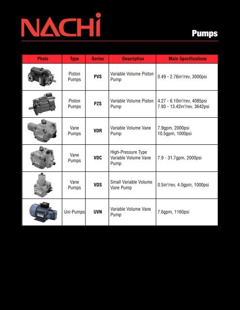
Pumps<br />
Photo Type Series Description Main Specifications<br />
<strong>Piston</strong><br />
Pumps<br />
<strong>Piston</strong><br />
Pumps<br />
Vane<br />
Pumps<br />
Vane<br />
Pumps<br />
Vane<br />
Pumps<br />
PVS<br />
PZS<br />
VDR<br />
VDC<br />
VDS<br />
Uni-Pumps UVN<br />
Variable Volume <strong>Piston</strong><br />
Pump<br />
Variable Volume <strong>Piston</strong><br />
Pump<br />
Variable Volume Vane<br />
Pump<br />
High-Pressure Type<br />
Variable Volume Vane<br />
Pump<br />
Small Variable Volume<br />
Vane Pump<br />
Variable Volume Vane<br />
Pump<br />
0.49 - 2.76in 3 /rev, 3000psi<br />
4.27 - 6.10in 3 /rev, 4085psi<br />
7.93 - 13.42in 3 /rev, 3642psi<br />
7.9gpm, 2000psi<br />
10.5gpm, 1000psi<br />
7.9 - 31.7gpm, 2000psi<br />
0.5in 3 /rev, 4.0gpm, 1000psi<br />
7.6gpm, 1160psi
PVS Series Variable<br />
Volume <strong>Piston</strong> Pumps<br />
PVS SERIES<br />
VARIABLE VOLUME PISTON PUMP<br />
0.49 to 2.76in 3 /rev<br />
3000psi<br />
*<br />
M<br />
0<br />
Discharge<br />
port<br />
¡Design No. 30 is applied on PVS-0B to make the pump more compact and lighter, and reduce noise.<br />
¡Production of PVS-3B has been discontinued. Use PZS-3B.<br />
¡Pressure adjustment 3 type has been added to PVS-1B-22 and PVS-2B-45. (Design No. 20 is applied only on<br />
PVS-2B-45*3.)<br />
Reliable fast response<br />
mechanism<br />
Pressure rate control response is fast.<br />
The construction is simple, which<br />
improves reliability and eliminates<br />
problems.<br />
Pressure balanced shoe in the<br />
lateral direction optimally<br />
utilizes the discharged fluid<br />
Pressure balance of the shoe and<br />
the swash plate in the lateral<br />
direction is accomplished by<br />
discharged fluid directed to the<br />
cavity of the shoe<br />
--- For a completely hydraulically<br />
balanced<br />
assembly. The smooth operation<br />
achieved contributes to the<br />
features of high efficiency, low<br />
noise and extended life.<br />
Features<br />
Energy-saving Type with<br />
Drastically Reduced Loss<br />
A NACHI-proprietary semi-circular barrel<br />
swash plate that receives pressure<br />
on its surface ensures a stable discharge<br />
volume at all times. This eliminates<br />
excess discharge volume, and<br />
enables the effective use of power corresponding<br />
to the load cycle.<br />
This "energy-saving type" conserves<br />
energy, reduces power loss, and helps<br />
to reduce hydraulic costs.<br />
Silent Type That Demonstrates<br />
Its Power Quietly<br />
Proprietary low-noise mechanisms are<br />
incorporated on the shoe, swash plate,<br />
valve plate, and other locations to<br />
Suction<br />
port<br />
Sharp cut-off characteristics<br />
obtained with simple adjusting<br />
mechanism<br />
*<br />
Drain<br />
port<br />
The NACHI flow adjusting mechanism,<br />
operating with the action of the<br />
semi-cylindrical swash plate, allows<br />
very sharp cut-off characteristics.<br />
Adjusting operation is easily made<br />
with a spanner tool.<br />
Special shaped fluid flow<br />
port reduces noise<br />
The special shaped fluid flow port and<br />
minute grooves have been developed<br />
to reduce noise and thus makes the<br />
operating sound negligible.<br />
The stable swash plate<br />
enhances various operational<br />
properties<br />
The swash plate a semi-cylindrical<br />
design concept is an advancement to<br />
the conventional type. In addition to<br />
the innovative form, the swash plate<br />
adopts special bearings to control<br />
sideway motion. Consequently, power<br />
is received directly regardless of<br />
changes in the load. Stable operations<br />
can be achieved.<br />
ensure silent operation. In particular, a<br />
semi-circular barrel swash plate stabilizes<br />
operation characteristics to ensure<br />
silent operation.<br />
P-1
P-2<br />
Specifications<br />
Model No.<br />
PVS-0B-8*0-E30<br />
1<br />
2<br />
3<br />
PVS-1B-16*0-(*)-E13<br />
1<br />
2<br />
3<br />
PVS-1B-22*0-(*)-E13<br />
1<br />
2<br />
3<br />
PVS-2B-35*0-(*)-E13<br />
1<br />
2<br />
3<br />
PVS-2B-45*0-(*)-E13<br />
1<br />
2<br />
3-(*)-E20<br />
Volume<br />
cm3 /rev<br />
(in3 /rev)<br />
8.0<br />
(0.49)<br />
16.5<br />
(1.01)<br />
22.0<br />
(1.34)<br />
35.0<br />
(2.<strong>14</strong>)<br />
45.0<br />
(2.76)<br />
¡Handling<br />
¡Cautions during Pump Installation<br />
and Piping<br />
zUse flexible couplings for connecting the<br />
pump shaft to the drive shaft, and prevent<br />
a radial or thrust load from being<br />
applied on the pump shaft.<br />
xFor centering of the pump shaft, limit the<br />
eccentricity between the drive shaft and<br />
hydraulic pump shaft to 0.05 mm, and<br />
keep the angle error within 1°.<br />
cSet the clamping length of couplings and<br />
hy-draulic pump shafts so that it is within<br />
at least 2/3 or more of the coupling width.<br />
vUse a sufficiently rigid pump mounting<br />
base.<br />
bSet the pressure on the pump suction<br />
side to -0.03 MPa or more (suction port<br />
flow velocity within 2 m/sec).<br />
nRaise part of the drain piping to above<br />
the topmost part of the pump body, and<br />
insert the return section of the drain piping<br />
into the hydraulic operating fluid.<br />
Also, observe the values in the following<br />
table to limit the drain back pressure to<br />
0.1 MPa.<br />
Model PVS-0B<br />
No.<br />
PVS-2B<br />
Item<br />
PVS-1B<br />
3/8"<br />
1/2"<br />
Pipe joint size<br />
or more or more<br />
φ7.6 mm dia or φ12 mm<br />
Pipe I.D<br />
more dia or more<br />
Pipe length 1m or less 1m or less<br />
¡Management of Hydraulic Operating<br />
Fluid<br />
zUse good-quality hydraulic operating<br />
fluid, and use within a kinematic viscosity<br />
range of 20 to 200 mm 2 /sec during<br />
operation. Use an R&O type and wearresistant<br />
type of IS-OGV32 to 68 or<br />
equivalent.<br />
The optimum kinematic viscosity during<br />
operation is 20 to 50 mm 2 /sec.<br />
xThe operating temperature range is 5 to<br />
60°C. When the oil temperature at start-<br />
Discharge volume at no-load r/min (gpm)<br />
Pressure<br />
adjustment range<br />
MPa<br />
Allowable<br />
peak<br />
pressure<br />
MPa<br />
Revolution<br />
speed min<br />
(PSI)<br />
(PSI)<br />
-1 Weight<br />
Lb<br />
1000min-1 1200min-1 1500min-1 1800min-1 2 ~ 13.5 (286 ~ 500)<br />
Min. Max.<br />
8.0<br />
(2.1)<br />
9.6<br />
(2.5)<br />
12.0<br />
(3.2)<br />
<strong>14</strong>.4<br />
(3.8)<br />
2 ~ 17.5 (286 ~ 1000)<br />
3 ~ <strong>14</strong>. (429 ~ 2000)<br />
25<br />
(3643)<br />
500 2000 17.0<br />
3 ~ 21. (429 ~ 3000)<br />
16.5<br />
(4.4)<br />
19.8<br />
(5.2)<br />
24.7<br />
(6.5)<br />
29.7<br />
(7.8)<br />
2 ~ 13.5 (286 ~ 500)<br />
2 ~ 17.5 (286 ~ 1000)<br />
3 ~ <strong>14</strong>. (429 ~ 2000)<br />
25<br />
(3643)<br />
500 2000 23.0<br />
3 ~ 21. (429 ~ 3000)<br />
22.0<br />
(5.8)<br />
26.4<br />
(7.0)<br />
33.0<br />
(8.7)<br />
39.6<br />
(10.5)<br />
2 ~ 13.5 (286 ~ 500)<br />
2 ~ 17.5 (286 ~ 1000)<br />
3 ~ <strong>14</strong>. (429 ~ 2000)<br />
25<br />
(3643)<br />
500 2000 23.0<br />
3 ~ 21. (429 ~ 3000)<br />
35.0<br />
(9.2)<br />
42.0<br />
(11.1)<br />
52.5<br />
(13.9)<br />
63.0<br />
(16.6)<br />
2 ~ 13.5 (286 ~ 500)<br />
2 ~ 17.5 (286 ~ 1000)<br />
3 ~ <strong>14</strong>. (429 ~ 2000)<br />
25<br />
(3643)<br />
500 2000 51.0<br />
3 ~ 21. (429 ~ 3000)<br />
45.0<br />
(11.9)<br />
54.0<br />
(<strong>14</strong>.3)<br />
67.5<br />
(17.9)<br />
81.0<br />
(21.5)<br />
2 ~ 13.5 (286 ~ 500)<br />
2 ~ 17.5 (286 ~ 1000)<br />
3 ~ <strong>14</strong>. (429 ~ 2000)<br />
25<br />
(3643)<br />
500 2000 51.0<br />
3 ~ 21. (429 ~ 3000)<br />
Note) 1. The standard direction of rotation is clockwise when viewed from the shaft end. Consult your agent separately for a counterclockwise direction of rotation.<br />
2. A keyed straight shaft is standard. For details on spline shafts, consult your agent separately.<br />
up is 5°C or less, warm up the hydraulic<br />
pump by low-pressure, low-operation<br />
speed operation until the oil temperature<br />
reaches 5°C.<br />
cProvide a suction strainer with a filtering<br />
grade of about 100µm (150 mesh). Be<br />
sure to provide a return line filter of<br />
grade 20µm or less on the return line to<br />
the tank. (When the hydraulic pump is<br />
used at a high pressure of <strong>14</strong> MPa or<br />
more, we recommend providing a filter<br />
of 10µm or less.<br />
vManage the hydraulic operating fluid so<br />
that contamination is maintained at class<br />
NAS10 or lower.<br />
bUse hydraulic operating fluid within an<br />
operating ambient temperature of 0 to<br />
60°C.<br />
¡Cautions at Startup<br />
zBefore you start pump operation, fill the<br />
pump body with clean hydraulic operating<br />
fluid via the lubrication port.<br />
Model No. Injection amount cm 3<br />
PVS-0B-8 220<br />
PVS-1B-16, 22 300<br />
PVS-2B-35, 45 650<br />
xAn unload is required when the motor is<br />
started under condition λ-Δ. Consult your<br />
agent regarding the circuit.<br />
cMake sure that the pump operates in the<br />
direction of rotation the same as that indicated<br />
by the arrow on the pump body.<br />
vAir entering the pump or pipes may<br />
cause noise or vibration. At startup, set<br />
the pump discharge side to a noload<br />
state, and operate the pump in the inching<br />
mode to release any air in the pump<br />
or pipes.<br />
bProvide an air bleed valve in circuits<br />
where it is difficult to release air at startup.<br />
¡How to Set Pressure and Discharge<br />
Volume<br />
The default pump discharge volume is<br />
set to "maximum" and default discharge<br />
pressure is set to "minimum". Change<br />
the discharge volume and discharge<br />
pressure settings according to your particular<br />
operating conditions.<br />
[Pressure adjustment]<br />
Turning the pressure<br />
adjusting<br />
screw CW increases<br />
the pressure.<br />
[Discharge volume<br />
adjustment]<br />
Turning the flow<br />
rate adjusting screw<br />
CW decreases the<br />
discharge volume.<br />
Discharge volume<br />
adjustment range<br />
Discharge<br />
volume<br />
Discharge<br />
volume<br />
CW<br />
CW<br />
CCW<br />
Pressure<br />
Pressure<br />
adjustment range<br />
CCW<br />
Pressure<br />
Note)<br />
· For details regarding the relationship between<br />
flow rate adjustment length rand pump capacity<br />
q, see the tables provided in the installation<br />
dimension drawings for each of the pumps.<br />
· Firmly tighten the lock nuts after you have finished<br />
adjustments.
Explanation of model No<br />
PVS – 1 B – 16 N 2 – ( ) –<br />
[Note]<br />
¡Variable control mechanism<br />
[Example 1]<br />
N*: Pressure<br />
compensation type<br />
(manual mode)<br />
PVS-1B-16N2<br />
Discharge volume<br />
Discharge volume<br />
13<br />
Design code 30: PVS-0B<br />
12: PVS-1B, PVS-2B (Rc piping)<br />
13: PVS-1B, PVS-2B (SAE piping)<br />
20: PVS-2B-45N3<br />
Pressure compensating range [See Note]<br />
Control Type [See Note]<br />
Max. volume cc/rev 8, 16, 22, 35, 45<br />
(in3 No code: Rc for piping and metric for others<br />
E: SAE for piping and metric for others<br />
Aux. symbol No code: Side port type<br />
Z: Axial port type<br />
/rev 0.5, 1.0, 1.3, 2.1, 2.8)<br />
Mounting B: flang mounting<br />
A: Foot mounting<br />
Pump size: 0, 1, 2<br />
PVS series variable volume piston pump<br />
Standard type<br />
N* : Pressure compensation type (manual<br />
mode)<br />
Option type<br />
P* : Pressure compensation type (remote<br />
control mode)<br />
N*Q* : 2-pressure, 2-flow rate control<br />
R* A &* : Solenoid cutoff control<br />
S<br />
W* A &* : 2-pressure control<br />
S<br />
RQ* A&* : 2-pressure, 2-flow rate<br />
S<br />
control w/ solenoid cutoff<br />
C* A &* : 2-cutoff control<br />
S<br />
[Example 4]<br />
R*S*: Solenoid<br />
cutoff control<br />
PVS-1B-16R2S2<br />
Solenoid specifications<br />
200V 50/60Hz<br />
SS-G01<br />
Discharge volume<br />
[Example 7]<br />
C*S*: 2-cutoff control<br />
PVS-1B-16C2S2<br />
Solenoid specifications<br />
200V 50/60Hz<br />
SS-G01<br />
N2:3-<strong>14</strong>MPa<br />
Discharge pressure<br />
P2:3-<strong>14</strong>MPa<br />
sol"ON"<br />
sol"OFF"<br />
Discharge pressure<br />
C2:3-<strong>14</strong>MPa<br />
sol"ON"<br />
sol"OFF"<br />
Discharge pressure<br />
¡* : Pressure adjustment range<br />
0 : 2 ~ 3.5MPa {286 ~ 500psi}<br />
1 : 2 ~ 7MPa {286 ~ 1000psi}<br />
2 : 3 ~ <strong>14</strong>MPa {429 ~ 2000psi}<br />
3 : 3 ~ 21MPa {429 ~ 3000psi}<br />
¡&* : Applicable to solenoid specifications A, S<br />
A&* : SA-G01<br />
S&* : SS-G01<br />
1 : 100V 50/60Hz<br />
2 : 200V 50/60Hz<br />
3 : DC12V<br />
4 : DC24V<br />
5 : AC115V 60Hz<br />
6 : AC230V 60Hz<br />
[Example 2]<br />
P*: Pressure<br />
compensation type<br />
(remote control mode)<br />
PVS-1B-16P2<br />
Discharge volume<br />
Discharge volume<br />
[Example 5]<br />
W*S*: 2-pressure control<br />
PVS-1B-16W2S1<br />
Solenoid specifications<br />
100V 50/60Hz<br />
SS-G01<br />
P2:3-<strong>14</strong>MPa<br />
Discharge pressure<br />
W2:3-<strong>14</strong>MPa<br />
sol"ON"<br />
sol"OFF"<br />
Discharge pressure<br />
[Example 3]<br />
N*Q*: 2-pressure,<br />
2-flow rate control<br />
PVS-1B-16N2Q1<br />
[Example 6]<br />
RQ*S*: 2-pressure,<br />
2-flow rate control w/<br />
solenoid cutoff<br />
PVS-1B-16RQ2S1<br />
Solenoid specifications<br />
100V 50/60Hz<br />
SS-G01<br />
❚NQ, RS, WS, RQS and CS types are not available for the PVS-0B-8, and the NQ, RQS and CS types are not available<br />
for the PVS-1B- 16<br />
-Z and PVS-2B-35<br />
22 45 -Z.<br />
Discharge volume<br />
Discharge volume<br />
Q1:2-7MPa<br />
N2:3-<strong>14</strong>MPa<br />
Discharge pressure<br />
R2:3-<strong>14</strong>MPa<br />
sol"ON"<br />
sol"OFF"<br />
Discharge pressure<br />
P-3
P-4<br />
Variable Control Mechanisms<br />
Standard type<br />
Symbol External View Characteristics Hydraulic Circuit Explanation<br />
N<br />
Option type<br />
P<br />
NQ<br />
RS<br />
(RA)<br />
WS<br />
(WA)<br />
RQS<br />
(RQA)<br />
CS<br />
Flow rate<br />
adjusting screw<br />
Pilot port<br />
Flow rate<br />
adjusting screw<br />
Drain port<br />
NACHI<br />
Pressure<br />
adjusting screw<br />
NACHI<br />
Drain port<br />
q1 flow rate adjusting screw<br />
q2 flow rate Drain port<br />
adjusting screw<br />
Pressure<br />
adjusting screw<br />
(at solenoid ON)<br />
P1 pressure adjusting screw<br />
Flow rate<br />
adjusting screw<br />
Pressure<br />
adjusting screw<br />
(at solenoid OFF)<br />
Flow rate<br />
adjusting screw<br />
SOL b<br />
P2 pressure<br />
adjusting screw<br />
(at solenoid ON)<br />
q2 flow rate<br />
adjusting screw<br />
q1 flow rate<br />
adjusting screw<br />
SOL b<br />
SOL b<br />
NACHI<br />
NACHI<br />
NACHI<br />
Differential pressure<br />
adjusting screw<br />
(adjustment forbidden)<br />
P2 pressure<br />
adjusting screw<br />
Drain port<br />
Pressure<br />
adjusting screw<br />
(at solenoid ON)<br />
Drain port<br />
NACHI<br />
Drain port<br />
P1 pressure adjusting screw<br />
q1 flow rate adjusting screw<br />
q2 flow rate Drain port<br />
adjusting screw<br />
(CA) NACHI<br />
P2 pressure adjusting screw<br />
Differential pressure<br />
adjusting screw<br />
(adjustment forbidden)<br />
Discharge volume<br />
Discharge volume<br />
Discharge volume<br />
Discharge volume<br />
Discharge volume<br />
Discharge volume<br />
Discharge volume<br />
q1<br />
q2<br />
Discharge pressure<br />
Discharge pressure<br />
P1<br />
P2<br />
Discharge pressure<br />
SOL<br />
"OFF"<br />
q1<br />
SOL SOL<br />
"OFF" "ON"<br />
Discharge pressure<br />
SOL<br />
"ON"<br />
P1 P2<br />
Discharge pressure<br />
q2 P1<br />
q2<br />
SOL OFF P2<br />
Discharge pressure<br />
q1<br />
SOL ON<br />
SOL ON<br />
P1 SOL OFF P2<br />
Discharge pressure<br />
*<br />
*<br />
*<br />
*<br />
*<br />
M<br />
*<br />
0<br />
Discharge<br />
port<br />
Suction<br />
port<br />
M<br />
0<br />
*<br />
Drain<br />
port<br />
Pilotport Discharge<br />
port<br />
Suction<br />
port<br />
*<br />
Drain<br />
port<br />
Discharge port<br />
M<br />
N<br />
0<br />
*<br />
M<br />
0<br />
Suction<br />
port<br />
Discharge port<br />
M<br />
0<br />
Suction<br />
port<br />
Drain<br />
port<br />
*<br />
Drain<br />
port<br />
Discharge port<br />
Suction<br />
port<br />
*<br />
Drain<br />
port<br />
Discharge port<br />
M<br />
N<br />
*<br />
0 Suction Drain<br />
port port<br />
Discharge port<br />
* M<br />
N<br />
0<br />
*<br />
Suction Drain<br />
port port<br />
Pressure compensation type<br />
(manual system)<br />
When the discharge pressure<br />
reaches the preset volume<br />
set by the pressure compensator,<br />
the discharge volume is<br />
automatically reduced to hold<br />
the pressure at the set pressure.<br />
Pressure compensation type<br />
(remote control mode)<br />
This mode demonstrates the<br />
same characteristics as the<br />
manual mode.<br />
The discharge pressure can be<br />
adjusted by external pilot pressure.<br />
The discharge volume can<br />
be adjusted manually. Note 2)<br />
2-pressure, 2-flow rate control<br />
type<br />
The discharge volume<br />
changes in two stages by the<br />
pump's built-in sequence<br />
valve. This allows conventional<br />
high/ low pressure control<br />
to be performed on a single<br />
pump unit, and save energy in<br />
the hydraulic circuit.<br />
Solenoid cutoff control type<br />
A solenoid valve for unload is<br />
integrated into the pressure<br />
compensation type to minimize<br />
energy loss when pump<br />
output is not required. Only a<br />
slight amount of heat is generated.<br />
2-pressure control type<br />
Two pressure compensation<br />
types can be obtained by switching<br />
the solenoid valve ON/OFF.<br />
Two types of output control are<br />
possible with the actuator set to<br />
a constant speed.<br />
2-pressure, 2-flow rate control<br />
type w/ solenoid cutoff<br />
The discharge volume can be<br />
changed in two stages by the<br />
sequencer valve and solenoid<br />
valve for unload mounted on<br />
the pump, and unloading is<br />
possible when pressure oil is<br />
not required.<br />
2-cutoff control type<br />
Two types of pressure - flow<br />
rate characteristics can be<br />
obtained by the solenoid<br />
valve and cylinder mounted<br />
on the pump.<br />
Note 1) Many other variable control mechanism are also available in addition to those in the above table. Please consulat your agent for details.<br />
Note 2) We recommend ZR-T02-*-5895* as the remote control valve. For details, consult your agent. Prevent the pipe volume up to the remote control valve from falling<br />
below 150cm 3 .
Pressure Compensation Type<br />
PVS-0B-8N*-E30<br />
Installation Dimension Drawing<br />
Cross-sectional Drawing<br />
33 34 27 17 22 25 16 20 10 38 35 28 15 12 11 24 26 21 18<br />
40<br />
39<br />
37<br />
36<br />
29<br />
2<br />
5<br />
30<br />
19<br />
<strong>14</strong><br />
4<br />
Manual mode: standard type<br />
List of Sealing Parts<br />
Typical characteristics at hydraulic operating fluid kinematic viscosity of 32 mm2 Parts marked by an asterisk "*" are not available on the market.<br />
Consult your agent.<br />
/s<br />
Efficiency Curves Pressure-Flow Curves Input Power Curves<br />
Performance Curves<br />
6<br />
Input Power at Deadhead<br />
9<br />
7<br />
13<br />
8<br />
1 31 32<br />
23<br />
3<br />
Part No. Part Name Part No. Part Name Part No. Part Name<br />
1<br />
2<br />
3<br />
4<br />
5<br />
6<br />
7<br />
8<br />
9<br />
10<br />
11<br />
12<br />
13<br />
<strong>14</strong><br />
Noise Level<br />
Body<br />
Case<br />
Shaft<br />
Cylinder barrel<br />
Valve plate<br />
<strong>Piston</strong><br />
Shoe<br />
Shoe holder<br />
Barrel holder<br />
Swash plate<br />
Thrust bush<br />
Spring holder<br />
Gasket<br />
Spring C<br />
15<br />
16<br />
17<br />
18<br />
19<br />
20<br />
21<br />
22<br />
23<br />
24<br />
25<br />
26<br />
27<br />
28<br />
cm3 Pump capacity q cm<br />
/rev<br />
3 /rev<br />
Relationship between flow rateadjustme<br />
length ( ) and pump capacity (q)<br />
10<br />
8<br />
6<br />
4<br />
3 Flow rate adjustment range<br />
2<br />
5 10<br />
15<br />
Flow rate adjustment length mm<br />
Spring S<br />
Control piston<br />
Guide pin<br />
Parallel key<br />
Retainer<br />
Needle<br />
Ball bearing<br />
Needle bearing<br />
Oil seal<br />
Snap ring<br />
Snap ring<br />
Snap ring<br />
O-ring<br />
O-ring<br />
PVS-0B-8N -30<br />
Set a flow rate adjustment length within<br />
the above range. Oil will leak if the pump<br />
is operated below the adjustment range<br />
lower limit.<br />
29<br />
30<br />
31<br />
32<br />
33<br />
34<br />
35<br />
36<br />
37<br />
38<br />
39<br />
40<br />
Parallel pin<br />
Spring pin<br />
Hexagon socket head bolt<br />
Cross-recessed countersunk<br />
head screw<br />
Hexagon socket<br />
set screw<br />
Hexagon nut<br />
Hexagon plug<br />
Metal plug<br />
Nameplate<br />
Lubrication port plate<br />
CAUTION plate<br />
Rivet<br />
Part<br />
No.<br />
Part Name Q'ty<br />
Size<br />
PVS-0B-8<br />
Remarks<br />
13 Packing 1 PS46-100000 3 Bond<br />
23 Oil seal 1 TCV-254511 N.O.K<br />
27 O-ring 1 1B-P9 JIS B 2401<br />
28 O-ring 1 1B-P11 JIS B 2401<br />
P-5
P-6<br />
Installation Dimension Drawing<br />
PVS-1B- 16 N*-E13 (Side Port Type)<br />
22<br />
PVS-1B- 16 N*-Z13 (Axial Port Type)<br />
22<br />
31<br />
19<br />
34<br />
29<br />
23<br />
40<br />
36<br />
Cross-sectional Drawing<br />
41<br />
16<br />
17<br />
35<br />
2 5 26 <strong>14</strong> 4 20<br />
6<br />
7<br />
38<br />
9<br />
15 21 39 30<br />
8<br />
13<br />
10<br />
11<br />
22<br />
12<br />
28<br />
33 1 32<br />
25<br />
24<br />
3<br />
18<br />
27<br />
37<br />
Pump Displacement<br />
List of Sealing Parts<br />
Part No. Part Name Part No. Part Name<br />
1<br />
2<br />
3<br />
4<br />
5<br />
6<br />
7<br />
8<br />
9<br />
10<br />
11<br />
12<br />
13<br />
<strong>14</strong><br />
15<br />
16<br />
17<br />
18<br />
19<br />
20<br />
21<br />
The relation between flow adjusting<br />
length (r) and pump displacement<br />
(q)<br />
Body<br />
Case<br />
Shaft<br />
Cylinder barrel<br />
Valve plate<br />
<strong>Piston</strong><br />
Shoe<br />
Shoe holder<br />
Barrel holder<br />
Swash plate<br />
Thrust bush<br />
Seal holder<br />
Gasket<br />
Spring C<br />
Spring S<br />
Control piston<br />
Needle<br />
Key<br />
Nut<br />
Retainer<br />
Plug<br />
22<br />
23<br />
24<br />
25<br />
26<br />
27<br />
28<br />
29<br />
30<br />
31<br />
32<br />
33<br />
34<br />
35<br />
36<br />
37<br />
38<br />
39<br />
40<br />
41<br />
Ball bearing<br />
Needle bearing<br />
Oil seal<br />
Snap ring<br />
Snap ring<br />
Snap ring<br />
O-ring<br />
O-ring<br />
O-ring<br />
Pin<br />
Hexagon socket head bolt<br />
Cross-recessed countersunk<br />
head screw<br />
Hexagon socket set screw<br />
Metal plug<br />
Nameplate<br />
CAUTION plate<br />
Spring holder<br />
Lubrication port plate<br />
Rivet<br />
Guide pin<br />
Part No. Name Q'ty Size Remarks<br />
13 Gasket 1 PS46-101000 Nihon Gasket<br />
24 Oil seal 1 TCN-254511 N.O.K<br />
28 O-ring 1 1B-G55 JIS B 2401<br />
29 O-ring 1 1B-P9 JIS B 2401<br />
30 O-ring 1 1B-P<strong>14</strong> JIS B 2401<br />
Parts marked by an asterisk "*" are not available on the market.<br />
Consult your agent.
Performance Curves Typical characteristics at hydraulic operating fluid kinematic viscosity of 32 mm 2 /s<br />
PVS-1B-16N*-(Z)-E13<br />
Performance Curves<br />
PVS-1B-22N*-(Z)-E13<br />
Oil ISO VG 32 Oil temp. 50°C (122°F)<br />
Efficiency Curves Pressure-Flow Curves<br />
Input Power at Deadhead Noise Level Oil Temperature Rise Curves<br />
Typical characteristics at hydraulic operating<br />
fluid kinematic viscosity of 32 mm 2 /s<br />
Oil ISO VG 32 Oil temp. 50°C (122°F)<br />
Efficiency Curves Pressure-Flow Curves<br />
Input Power at Deadhead Noise Level<br />
Input Power Curves<br />
Input Power Curves<br />
P-7
P-8<br />
Installation Dimension Drawing<br />
PVS-2B- 35 N*- E13 (Side Port Type)<br />
45 E20<br />
PVS-2B- 35 N*-Z- E13 (Axial Port Type)<br />
45 E20<br />
Cross-sectional Drawing<br />
PVS-2B- 35 N*-(Z)- E13<br />
45 E20<br />
35<br />
40<br />
23<br />
43<br />
19<br />
31<br />
30<br />
32<br />
42<br />
PVS-2B-45N3-(Z)-20<br />
16<br />
36<br />
17<br />
0<br />
24.9 _ 0.5<br />
39 15 21 41 29<br />
37 2 5 27 <strong>14</strong> 4 20 9 8 13 10 11 34 26 24 1<br />
35<br />
40<br />
23<br />
47<br />
46<br />
45<br />
43<br />
19<br />
31<br />
30<br />
32<br />
Shaft<br />
dimension<br />
42<br />
16<br />
36<br />
17<br />
6<br />
7<br />
39 15 21 41 29<br />
37 2 5 27 <strong>14</strong> 4 20 9 8 13 10 11 34 44 26 24 1<br />
6<br />
7<br />
22<br />
22<br />
12<br />
28<br />
33 38<br />
12<br />
mm (inch)<br />
28<br />
33<br />
25<br />
3<br />
18<br />
25<br />
3<br />
18<br />
38<br />
Part<br />
No.<br />
1<br />
2<br />
3<br />
4<br />
5<br />
6<br />
7<br />
8<br />
9<br />
10<br />
11<br />
12<br />
13<br />
<strong>14</strong><br />
15<br />
Part Name<br />
Body<br />
Case<br />
Shaft<br />
Cylinder barrel<br />
Valve plate<br />
<strong>Piston</strong><br />
Shoe<br />
Shoe holder<br />
Barrel holder<br />
Swash plate<br />
Thrust bush<br />
Seal holder<br />
Gasket<br />
Spring C<br />
Spring S<br />
Part<br />
No.<br />
16<br />
17<br />
18<br />
19<br />
20<br />
21<br />
22<br />
23<br />
24<br />
25<br />
26<br />
27<br />
28<br />
29<br />
30<br />
List of Sealing Parts<br />
Part<br />
No.<br />
1<br />
2<br />
3<br />
4<br />
5<br />
6<br />
7<br />
8<br />
9<br />
10<br />
11<br />
12<br />
13<br />
<strong>14</strong><br />
15<br />
16<br />
Part Name<br />
Body<br />
Case<br />
Shaft<br />
Cylinder barrel<br />
Valve plate<br />
<strong>Piston</strong><br />
Shoe<br />
Shoe holder<br />
Barrel holder<br />
Swash plate<br />
Thrust bush<br />
Seal holder<br />
Gasket<br />
Spring C<br />
Spring S<br />
Control piston<br />
Part<br />
No.<br />
17<br />
18<br />
19<br />
20<br />
21<br />
22<br />
23<br />
24<br />
25<br />
26<br />
27<br />
28<br />
29<br />
30<br />
31<br />
32<br />
List of Sealing Parts<br />
Part Name<br />
Control piston<br />
Needle<br />
Key<br />
Nut<br />
Retainer<br />
Plug<br />
Ball bearing<br />
Needle bearing<br />
Oil seal<br />
Snap ring<br />
Snap ring<br />
Snap ring<br />
O-ring<br />
O-ring<br />
O-ring<br />
Part Name<br />
Needle<br />
Key<br />
Nut<br />
Retainer<br />
Plug<br />
Roller bearing<br />
Needle bearing<br />
Oil seal<br />
Snap ring<br />
Snap ring<br />
Snap ring<br />
O-ring<br />
O-ring<br />
O-ring<br />
Backup ring<br />
Pin<br />
Part<br />
No.<br />
31<br />
32<br />
33<br />
34<br />
35<br />
36<br />
37<br />
38<br />
39<br />
40<br />
41<br />
42<br />
43<br />
Part<br />
No.<br />
33<br />
34<br />
35<br />
36<br />
37<br />
38<br />
39<br />
40<br />
41<br />
42<br />
43<br />
44<br />
45<br />
46<br />
47<br />
Part Name<br />
Backup ring<br />
Pin<br />
Hexagon socket<br />
head bolt<br />
Cross-recessed countersunk<br />
head screw<br />
Flow rate adjusting<br />
screw<br />
Metal plug<br />
Nameplate<br />
CAUTION plate<br />
Spring holder<br />
Guide<br />
Lubrication port<br />
Orifice<br />
Rivet<br />
Part No. Part Name Q'ty<br />
PVS-2B-35/45<br />
Size Remarks<br />
13 Gasket 1 * Nihon Gasket<br />
24 Oil seal 1 TCN-305011Z N.O.K<br />
28 O-ring 1 1B-G70 JIS B 2401<br />
29 O-ring 1 1B-P<strong>14</strong> JIS B 2401<br />
30 O-ring 1 1B-P11 JIS B 2401<br />
31 Backup ring 1 T2-P11 JIS B 2407<br />
Parts marked by an asterisk "*" are not available on the market. Consult your agent.<br />
Part No. Part Name Q'ty<br />
PVS-2B-45N3<br />
Part Name<br />
Hexagon socket head bolt<br />
Cross-recessed countersunk<br />
head screw<br />
Flow rate adjusting screw<br />
Metal plug<br />
Nameplate<br />
CAUTION plate<br />
Spring holder<br />
Guide<br />
Lubrication port plate<br />
Orifice<br />
Rivet<br />
Orifice<br />
Pin<br />
O-ring<br />
Plug<br />
Size Remarks<br />
13 Gasket 1 * Nihon Gasket<br />
24 Oil seal 1 TCN-305011Z N.O.K<br />
28 O-ring 1 1B-G70 JIS B 2401<br />
29 O-ring 1 1B-P<strong>14</strong> JIS B 2401<br />
30 O-ring 1 1B-P11 JIS B 2401<br />
46 O-ring 2 1B-P5 JIS B 2401<br />
31 Backup ring 1 T2-P11 JIS B 2407<br />
Parts marked by an asterisk "*" are not available on the market. Consult your agent.
Performance Curves Typical characteristics at hydraulic operating fluid kinematic viscosity of 32 mm 2 /s<br />
PVS-2B-35N*-(Z)-E13<br />
Efficiency Curves Pressure-Flow Curves Input Power Curves<br />
Input Power at Deadhead<br />
Performance Curves Typical characteristics at hydraulic operating fluid kinematic viscosity of 32 mm 2 /s<br />
PVS-2B-45N*-(Z)-E13, E20<br />
Noise Level<br />
Efficiency Curves Pressure-Flow Curves Input Power Curves<br />
Input Power at Deadhead<br />
Oil ISO VG 32 Oil temp. 50°C (122°F)<br />
Oil ISO VG 32 Oil temp. 50°C (122°F)<br />
Noise Level<br />
P-9
P-10<br />
Response Performance<br />
Model No.<br />
M<br />
0<br />
Pressure Compensator<br />
Test Circuit<br />
Piping volume 400 cm 3<br />
Q<br />
M<br />
Response Time (s) Surge Pressure MPa{kgf/cm 2 }<br />
t1 t2 PS<br />
PVS-0B-8 0.03 ~ 0.04 0.04 ~ 0.06 12 ~ 4{20.4 ~ 40.8}<br />
PVS-1B-16 0.05 ~ 0.06 0.07 ~ 0.08 <strong>14</strong> ~ 7{40.8 ~ 71.4}<br />
PVS-1B-22 0.05 ~ 0.06 0.07 ~ 0.08 15 ~ 8{51 ~ 81.6}<br />
PVS-2B-35 0.05 ~ 0.06 0.05 ~ 0.07 16 ~ 9{61.2 ~ 91.8}<br />
PVS-2B-45 0.05 ~ 0.06 0.05 ~ 0.07 16 ~ 9{61.2 ~ 91.8}<br />
Response performance changes according to pipe volume and size.<br />
Use an anti-surging valve to prevent surge voltage.<br />
12<br />
11<br />
10<br />
2<br />
3<br />
5<br />
<strong>14</strong><br />
13<br />
1<br />
9<br />
4<br />
Legend<br />
MPa<br />
t1<br />
Pressure MPa<br />
Ps<br />
<strong>14</strong>MPa<br />
FC<br />
(Q=0)<br />
1MPa<br />
(Q=MAX)<br />
SOL ON<br />
1MPa<br />
SOL OFF<br />
SOL OFF<br />
6<br />
8<br />
7<br />
Time s<br />
t2<br />
Part No. Part Name Part No. Part Name<br />
1<br />
2<br />
3<br />
4<br />
5<br />
6<br />
7<br />
Body<br />
Spool<br />
Holder<br />
Plunger<br />
Spring<br />
Retainer<br />
Pressure adjusting bolt<br />
8<br />
9<br />
10<br />
11<br />
12<br />
13<br />
<strong>14</strong><br />
List of Sealing Parts<br />
Nut<br />
O-ring<br />
O-ring<br />
O-ring<br />
Plug<br />
Plug<br />
Mounting bolt<br />
Part<br />
No.<br />
Name Q'ty<br />
Size<br />
For 0B, 1B, 2B<br />
9 O-ring 1 1A-P<strong>14</strong><br />
10 O-ring 3 1B-P6<br />
11 O-ring 1 1B-P10<br />
Note) O-ring 1A/B-** refers to JIS B2401-1A/B.
Pressure Compensation Type remote control mode<br />
Explanation of model No.: PVS – 0 B – 8 P –<br />
PVS-0B-8P*-E30<br />
PVS-1B- 16 P*-E13<br />
22<br />
Flow rate adjustment<br />
length<br />
Flow rate adjusting<br />
screw<br />
55(2.16)<br />
22 ( 1.862)<br />
47.5 ±0.2 1.877<br />
4–M10x16<br />
PVS-2B- 35 P*-E13, E20<br />
45<br />
Flow rate<br />
adjustment<br />
length<br />
69.5(2.73)<br />
22 ( )<br />
52.4 ±0.2 2.070<br />
2.055<br />
r<br />
r<br />
φ<br />
24<br />
(0.94)<br />
236(9.29)(MAX)<br />
77(3.03) 49.5(1.94)<br />
Drain port<br />
Pilot port<br />
3/8"SAE<br />
1/4"SAE<br />
Differential pressure adjusting screw<br />
(adjustment forbidden)<br />
6(0.23)<br />
22 ±0.2( )<br />
158(6.22)<br />
181(7.12)<br />
0.874<br />
0.858<br />
NACHI<br />
NACHI<br />
Max. pump capacity (cm3 /rev)<br />
Nominal 8, 16, 22, 35, 45 (in3 /rev 0.5, 1.0, 1.3, 2.1, 2.8)<br />
Pump size 0, 1, 2<br />
43(1.69)<br />
25.4<br />
(1.00)<br />
12.5(0.49)<br />
317(12.48)(MAX)<br />
Drain port Differential pressure<br />
1/2"SAE adjusting screw<br />
Pilot port pp (adjustment forbidden)<br />
Flow rate<br />
adjusting screw 1/4"SAE 88(3.46) 60(2.36)<br />
Lock nut<br />
6(0.23)<br />
φ<br />
28<br />
(1.10)<br />
53(2.08)<br />
38(1.49) 3<br />
(0.10)<br />
E30<br />
Installation Dimension Drawing<br />
2<strong>14</strong>(8.42)(MAX)<br />
164.5(6.74)(MAX)<br />
93.5(3.68)<br />
(flow rate adjust-<br />
r ment length)<br />
Pilot port<br />
10(0.39) 5(0.19)<br />
1/4"SAE<br />
Lock nut<br />
Flow rate<br />
adjusting screw<br />
Discharge port<br />
1/2"SAE<br />
127.5(5.01)<br />
<strong>14</strong>9.5(5.88)<br />
49.5(1.94)<br />
6(0.23)<br />
18 Drain port<br />
(0.70)<br />
3/8"SAE<br />
42.5(1.69)<br />
25.4 5(0.19)<br />
(1.00)<br />
11(0.43)<br />
Design No.<br />
E30: PVS-0*<br />
E13: PVS-1*, PVS-2*<br />
E20: PVS-2*-45P3 only<br />
Pressure adjustment range<br />
0: 2- 3.5MPa {286-500psi}<br />
1: 2- 7MPa {286-1000psi}<br />
2: 3-<strong>14</strong>MPa {429-2000psi}<br />
3: 3-21MPa {429-3000psi}<br />
P: Pressure compensation type (remote control mode)<br />
A<br />
B<br />
Key width<br />
0<br />
4.76 –0.012( ) 0.187<br />
0.186<br />
–0.03<br />
21.2 –0.25( ) 0.834<br />
–0.036<br />
φ 19.05 –0.021( )<br />
0.824<br />
0.750<br />
0.749<br />
Key width<br />
0<br />
–0.012 0.187<br />
0.186<br />
–0.036 φ 82.6 –0.071( ) 3.250<br />
–0.03<br />
21.2 –0.25( )<br />
3.249<br />
0.834<br />
–0.036<br />
φ 19.05 –0.021( )<br />
0.824<br />
0.750<br />
4.76 ( )<br />
0.749<br />
5(0.19)<br />
Key width<br />
4.76 6.3 ( )<br />
+0.015<br />
–0.010 0.248<br />
0.247<br />
45(1.77)<br />
4–M10x16<br />
192(7.55)<br />
15(0.69)<br />
SAEJ518b-1<br />
<strong>14</strong>4(5.66)<br />
<strong>14</strong>6(5.74)<br />
222(8.74)<br />
172(6.77)<br />
in A B<br />
3 Discharge port<br />
/rev Pressure<br />
Range<br />
2.1<br />
2.8<br />
0 3<br />
0 2<br />
3<br />
13D<br />
20D<br />
Design<br />
1.039<br />
26.2 22 ±0.2( 1.023)<br />
No.<br />
24.922 ( )<br />
00<br />
–0.5 0.980<br />
0.960<br />
27.85 22 ( )<br />
00<br />
–0.25 1.096<br />
φ 25.385 22 ( )<br />
1.086<br />
00<br />
–0.025 0.999<br />
22.23 22 ( )<br />
0.998<br />
00<br />
–0.021 0.875<br />
φ<br />
0.843<br />
φ 101.6 82.6 ( )<br />
0<br />
–0.051 4.000<br />
3.997<br />
–0.036 φ 82.6 –0.071( ) 3.250<br />
3.249<br />
Discharg<br />
1/2"SAE<br />
width<br />
012( ) 0.187<br />
0.186<br />
–0.036 φ 82.6 –0.071( ) 3.250<br />
3.249<br />
<strong>14</strong>2(5.59)<br />
78(3.07)<br />
Discharge port<br />
1/2"SAE<br />
88(3.46)<br />
73(2.87)<br />
11<br />
(0.43)<br />
47(1.85)<br />
29(1.<strong>14</strong>) 3(0.11)<br />
Lubrication port<br />
53.2(2.09)<br />
106.4(4.18)<br />
110(4.33)<br />
130(5.11)<br />
60(2.36) Lubrication port<br />
42(1.65)<br />
Lubrication port<br />
11(0.43)<br />
77(3.03)<br />
132(5.19)<br />
3<br />
(0.11)<br />
82(3.22)<br />
137(5.39)<br />
3(0.11)<br />
13(0.51)<br />
104(4.09)<br />
172(6.77)<br />
65(2.55)<br />
Max. pump capacity q<br />
cm3 /rev<br />
Suction port<br />
3/4"SAE<br />
Discharge port<br />
SAEJ518b-3/4<br />
106.4(4.18)<br />
124(4.88)<br />
130(5.11)<br />
Suction port<br />
SAEJ518b-1<br />
R46(1.81)<br />
52(2.04)<br />
6(0.23)<br />
49(1.92)<br />
SAEJ518b-11/4 Suction port<br />
P-Q Characteristics<br />
Set by remote<br />
control V<br />
Discharge pressure P MPa<br />
P-11
P-12<br />
2-pressure, 2-flow Rate Control Type<br />
Explanation of model No.: PVS – 1 B – 16 N 3 Q 1 –<br />
PVS-1B- 16 N*Q*-E13<br />
22<br />
q1 flow rate<br />
adjusting screw<br />
q2 flow rate<br />
adjusting screw<br />
22 ( )<br />
47.5 ±0.2 1.877<br />
1.862<br />
4–M10x16<br />
PVS-2B- 35 N*Q*-E13, E20<br />
45<br />
q1 flow rate<br />
adjusting screw<br />
q2 flow rate<br />
adjusting screw<br />
22 ( )<br />
52.4 ±0.2 2.070<br />
2.055<br />
4–M10x16<br />
296(11.65)(MAX)<br />
77(3.03) 49.5(1.94)<br />
Drain port<br />
3/8"SAE<br />
P2 pressure 23(0.90)<br />
adjusting screw (MIN)<br />
6(0.23)<br />
φ<br />
24<br />
(0.94)<br />
352(13.85)(MAX)<br />
φ<br />
28<br />
(1.10)<br />
22 ±0.2( )<br />
158(6.22)<br />
181(7.12)<br />
0.874<br />
0.858<br />
Drain port<br />
1/2"SAE<br />
NACHI<br />
1.039<br />
26.2 22 ±0.2( 1.023)<br />
192(7.55)<br />
222(8.74)<br />
NACHI<br />
Pump size 1, 2<br />
Installation Dimension Drawing<br />
88(3.46)<br />
P2 pressure<br />
adjusting screw<br />
60(2.36)(Min)<br />
15(0.69)<br />
43(1.69)<br />
25.4<br />
(1.00)<br />
12.5(0.49)<br />
6(0.23)<br />
in 3 /rev<br />
2.1<br />
2.8<br />
Key width<br />
0<br />
4.76 –0.012( ) 0.187<br />
0.186<br />
5<br />
(0.19)<br />
–0.03<br />
21.2 –0.25( ) 0.834<br />
–0.036<br />
φ 19.05 –0.021( )<br />
0.824<br />
0.750<br />
0.749<br />
60(2.36)<br />
53(2.08)<br />
38(1.49)<br />
Pressure<br />
Range<br />
0 3<br />
0 2<br />
3<br />
–0.036 φ 82.6 –0.071( ) 3.250<br />
3.249<br />
Key width<br />
4.76 6.3 ( )<br />
+0.015<br />
–0.010 0.248<br />
0.247<br />
3<br />
(0.11)<br />
A<br />
B<br />
φ 101.6 82.6 ( )<br />
0<br />
–0.051 4.000<br />
3.997<br />
E13<br />
Pressure adjustment range N*: High-pressure adjustment range, P2<br />
Q*: Low-pressure adjustment range, P1<br />
0: 2- 3.5MPa {286-500psi}<br />
1: 2- 7MPa {286-1000psi}<br />
2: 3-<strong>14</strong>MPa {429-2000psi}<br />
3: 3-21MPa {429-3000psi}<br />
NQ: 2-pressure, 2-flow rate control<br />
Max. pump capacity (cm 3 /rev)<br />
Nominal 16, 22, 35, 45 (in 3 /rev 1.0, 1.3, 2.1, 2.8)<br />
Pressure compensator 42(1.65) Lubrication port<br />
88(3.46)<br />
73(2.87)<br />
11(0.43)<br />
P1 pressure<br />
adjusting screw<br />
3<br />
(0.11)<br />
Discharge port<br />
SAEJ518b-3/4<br />
107.5(4.23)(MAX)<br />
106.4(4.18)<br />
124(4.88)<br />
130(5.11)<br />
Suction port<br />
SAEJ518b-1<br />
Pressure compensator 45(1.77) Lubrication port<br />
Discharge port<br />
SAEJ518b-1<br />
A B<br />
13D<br />
20D<br />
Design<br />
No.<br />
24.922 ( )<br />
00<br />
–0.5 0.980<br />
0.960<br />
27.85 22 ( )<br />
00<br />
–0.25 1.096<br />
φ 25.385 22 ( )<br />
1.086<br />
00<br />
–0.025 0.999<br />
22.23 22 ( )<br />
0.998<br />
00<br />
–0.021 0.875<br />
φ<br />
0.843<br />
Design No. E13: PVS-1*, PVS-2*<br />
E20: PVS-2*-45N3Q*<br />
<strong>14</strong>4(5.66)<br />
<strong>14</strong>6(5.74)<br />
172(6.77)<br />
107.5(4.23)(MAX)<br />
82(3.22)<br />
52(2.04)<br />
137(5.39)<br />
13(0.51)<br />
104(4.09) 3<br />
(0.11)<br />
P1 pressure<br />
adjusting screw<br />
65(2.55)<br />
172(6.77)<br />
Suction port<br />
SAEJ518b-11/4<br />
Pump Model No. q2 Adjustment Range (in 3 /rev) Default q2 (Setting in 3 /rev)<br />
PVS-1B-16 0 ~ 0.6 0.20<br />
PVS-1B-22 0 ~ 0.8 0.26<br />
PVS-2B-35 0 ~ 1.1 0.42<br />
PVS-2B-45 0 ~ 1.4 0.54<br />
Note 1) The setting range of maximum pump capacity q1 varies according to the setting of q2.<br />
Note 2) Overall efficiency at a low flow rate is worse than at the maximum flow rate. Pay<br />
attention to this when selecting the motor capacity for the drive.<br />
Pump capacity q<br />
cm3 /rev (Note 2)<br />
Pump capacity q<br />
cm3 /rev (Note 2)<br />
P-Q Characteristics<br />
q1<br />
q2<br />
q1<br />
q2<br />
0 P1<br />
P2<br />
Discharge pressure P MPa<br />
P-Q Characteristics<br />
0 P1<br />
P2<br />
Discharge pressure P MPa
Solenoid Cutoff Control Type<br />
Explanation of model No.: PVS – 1 B – 16 R 2 S 1 – E13<br />
PVS-1B- 16 R* A *-E13<br />
22 S<br />
Pressure adjusting<br />
screw<br />
(at solenoid ON)<br />
Flow rate adjusting<br />
screw<br />
55(2.16)<br />
22 ( 1.862)<br />
47.5 ±0.2 1.877<br />
4–M10x16<br />
SOL b<br />
PVS-2B- 35 R* A *-E13, E20<br />
45 S<br />
Pressure adjusting<br />
screw<br />
(at solenoid ON)<br />
Lock nut<br />
Flow rate adjusting<br />
screw<br />
69.5(2.73)<br />
22 ( )<br />
52.4 ±0.2 2.070<br />
2.055<br />
4–M10x16<br />
φ<br />
24<br />
(0.94)<br />
199.8(7.86)<br />
Drain port<br />
3/8"SAE<br />
22 ±0.2( ) 12.5(0.49)<br />
158(6.22)<br />
181(7.12)<br />
0.874<br />
0.854<br />
SOL b<br />
φ<br />
28<br />
(1.10)<br />
NACHI<br />
317(12.48)(MAX)<br />
77(3.03) 49.5(1.94)<br />
47.4(1.86) 6(0.23)<br />
NACHI<br />
1.039<br />
26.2 22 ±0.2( 1.023)<br />
15(0.69)<br />
192(7.55)<br />
222(8.74)<br />
Pump size 1, 2<br />
Installation Dimension Drawing<br />
43(1.69) Key width<br />
0<br />
4.76 –0.012( )<br />
25.4 5(0.19)<br />
(1.00)<br />
0.187<br />
0.186<br />
106.4(4.18)<br />
Discharge port<br />
124(4.88)<br />
Suction port<br />
SAEJ518b-3/4<br />
130(5.11)<br />
SAEJ518b-1<br />
❚The coil surface temperature increases if this pump is kept continuously energized.<br />
Do not touch the surface of the coil directly with your hands.<br />
–0.03<br />
21.2 –0.25( ) 0.834<br />
–0.036<br />
φ 19.05 –0.021( )<br />
0.824<br />
0.750<br />
0.749<br />
Pilot port<br />
1/4"SAE<br />
Drain port<br />
1/2"SAE<br />
Differential pressure<br />
adjusting screw<br />
(adjustment forbidden)<br />
88(3.46) 60(2.36)<br />
6(0.23)<br />
–0.036 φ 82.6 –0.071( ) 3.250<br />
3.249<br />
53(2.08)<br />
38(1.49) 3<br />
(0.11)<br />
in 3 /rev<br />
2.1<br />
2.8<br />
Pressure<br />
Range<br />
0 3<br />
0 2<br />
3<br />
Key width<br />
4.76 6.3 ( )<br />
+0.015<br />
–0.010 0.248<br />
0.247<br />
A<br />
B<br />
φ 101.6 82.6 ( )<br />
0<br />
–0.051 4.000<br />
3.997<br />
Solenoid power supply 1: AC110-115V<br />
2: AC220-230V<br />
3: DC12V<br />
4: DC24V<br />
Solenoid specifications A: SA-G01<br />
S: SS-G01<br />
Pressure adjustment range<br />
0: 2- 3.5MPa {286-500psi}<br />
1: 2- 7MPa {286-1000psi}<br />
2: 3-<strong>14</strong>MPa {429-2000psi}<br />
3: 3-21MPa {429-3000psi}<br />
R<br />
A<br />
S : Solenoid cutoff control<br />
Max. pump capacity (cm 3 /rev)<br />
Nominal 16, 22, 35, 45 (in 3 /rev 1.0, 1.3, 2.1, 2.8)<br />
108(4.25)<br />
11(0.43)<br />
90.5(3.56)<br />
Discharge port<br />
SAEJ518b-1<br />
A B<br />
13D<br />
20D<br />
Design<br />
No.<br />
24.922 ( )<br />
00<br />
–0.5 0.980<br />
0.960<br />
27.85 22 ( )<br />
00<br />
–0.25 1.096<br />
φ 25.585 22 ( )<br />
1.086<br />
00<br />
–0.025 0.999<br />
22.23 22 ( )<br />
0.998<br />
00<br />
–0.021 0.875<br />
φ<br />
0.843<br />
42(1.65)<br />
45(1.77)<br />
<strong>14</strong>4(5.66)<br />
<strong>14</strong>6(5.74)<br />
172(6.77)<br />
Differential pressure<br />
adjusting screw<br />
(adjustment forbidden)<br />
Lubrication<br />
port<br />
82(3.22) 3(0.11)<br />
137(5.39)<br />
177(6.93)(SA-G01)<br />
213(8.38)(SS-G01)<br />
52(2.04)<br />
Differential pressure<br />
adjusting screw<br />
(adjustment forbidden)<br />
Lubrication port<br />
13(0.51)<br />
104(4.09) 3(0.11)<br />
172(6.77)<br />
194.5(7.65)(SA-G01)<br />
230.5(9.07)(SS-G01)<br />
65(2.55)<br />
Suction port<br />
SAEJ518b-11/4<br />
Pump capacity q<br />
cm3 /rev<br />
P-Q Characteristics<br />
SOL<br />
"OFF"<br />
Discharge pressure P MPa<br />
SOL<br />
"ON"<br />
P-13
P-<strong>14</strong><br />
2-pressure Control Type<br />
Explanation of model No.: PVS – 1 B – 16 W 2 S 1 – E13<br />
PVS-1B- 16 W* A *-E13<br />
22 S<br />
Pressure adjusting<br />
screw<br />
(at solenoid OFF)<br />
Flow rate<br />
adjusting screw<br />
55(2.16)<br />
22 ( 1.862)<br />
47.5 ±0.2 1.877<br />
4–M10x16<br />
SOL b<br />
22 ±0.2( ) 12.5(0.49)<br />
158(6.22)<br />
181(7.12)<br />
0.874<br />
0.854<br />
PVS-2B- 35 W* A *-E13, E20<br />
45 S<br />
Pressure adjusting<br />
screw<br />
(at solenoid OFF)<br />
Lock nut<br />
Flow rate adjusting<br />
screw<br />
69.5(2.73)<br />
4–M10x16<br />
22 ( )<br />
52.4 ±0.2 2.070<br />
2.055<br />
φ<br />
24<br />
(0.94)<br />
SOL b<br />
φ<br />
28<br />
(1.10)<br />
77(3.03) 49.5(1.94)<br />
6(0.23)<br />
NACHI<br />
Drain port<br />
3/8"SAE<br />
Pressure adjusting screw<br />
(at solenoid ON)<br />
43(1.69)<br />
25.4<br />
(1.00)<br />
Key width<br />
0<br />
4.76 –0.012( ) 0.187<br />
0.186<br />
5(0.19)<br />
–0.03<br />
21.2 –0.25( ) 0.834<br />
–0.036<br />
φ 19.05 –0.021( )<br />
0.824<br />
0.750<br />
0.749<br />
Discharge port<br />
106.4(4.18)<br />
Suction port<br />
SAEJ518b-3/4<br />
124(4.88)<br />
SAEJ518b-1<br />
130(5.11)<br />
❚The coil surface temperature increases if this pump is kept continuously energized.<br />
Do not touch the surface of the coil directly with your hands.<br />
–0.036 φ 82.6 –0.071( ) 3.250<br />
3.249<br />
317(12.48)(MAX)<br />
Pilot port pp<br />
1/2"SAE<br />
Drain port<br />
1/2"SAE<br />
Pressure adjusting<br />
screw (at solenoid ON)<br />
Differential pressure<br />
adjusting screw<br />
(adjustment forbidden)<br />
88(3.46) 60(2.36)<br />
6(0.23)<br />
Key width<br />
4.76 6.3 ( )<br />
+0.015<br />
–0.010 0.248<br />
0.247<br />
1.039<br />
26.2 22 ±0.2( 1.023)<br />
15(0.59)<br />
192(7.55)<br />
222(8.74)<br />
NACHI<br />
Pump size 1, 2<br />
Installation Dimension Drawing<br />
53(2.08)<br />
38(1.49) 3(0.11)<br />
in 3 /rev<br />
2.1<br />
2.8<br />
Pressure<br />
Range<br />
0 3<br />
0 2<br />
3<br />
A<br />
B<br />
φ 101.6 82.6 ( )<br />
0<br />
–0.051 4.000<br />
3.997<br />
A B<br />
13D<br />
20D<br />
Design<br />
No.<br />
24.922 ( )<br />
00<br />
–0.5 0.980<br />
0.960<br />
27.85 22 ( )<br />
00<br />
–0.25 1.096<br />
φ 25.585 22 ( )<br />
1.086<br />
00<br />
–0.025 0.999<br />
22.23 22 ( )<br />
0.998<br />
00<br />
–0.021 0.875<br />
φ<br />
0.843<br />
Solenoid power supply 1: AC110-115V<br />
2: AC220-230V<br />
3: DC12V<br />
4: DC24V<br />
Solenoid specifications A: SA-G01<br />
S: SS-G01<br />
Pressure adjustment range<br />
0: 2- 3.5MPa {286-500psi}<br />
1: 2- 7MPa {286-1000psi}<br />
2: 3-<strong>14</strong>MPa {429-2000psi}<br />
3: 3-21MPa {429-3000psi}<br />
W<br />
A<br />
S : 2-pressure control<br />
Max. pump capacity (cm3 /rev)<br />
Nominal 16, 22, 35, 45 (in3 /rev 1.0, 1.3, 2.1, 2.8)<br />
90.5(3.56)<br />
127(5.00)<br />
11(0.11)<br />
45(1.77)<br />
42(1.65)<br />
Differential pressure<br />
adjusting screw<br />
(adjustment forbidden)<br />
Lubrication port<br />
Differential pressure<br />
adjusting screw<br />
(adjustment forbidden)<br />
Lubrication port<br />
13(0.51)<br />
104(4.09) 3(0.11)<br />
172(6.77)<br />
212.5(8.36)(SA-G01)<br />
248.5(9.78)(SS-G01)<br />
82(3.22) 3<br />
137(5.39) (0.11)<br />
195(7.69)(SA-G01)<br />
231(9.09)(SS-G01)<br />
Discharge port <strong>14</strong>4(5.66)<br />
Suction port<br />
SAEJ518b-1<br />
<strong>14</strong>6(5.74)<br />
SAEJ518b-11/4<br />
172(6.77)<br />
65(2.55)<br />
52(2.04)<br />
Pump capacity q<br />
cm3 /rev<br />
P-Q Characteristics<br />
SOL<br />
"OFF"<br />
SOL<br />
"ON"<br />
P1 P2<br />
Discharge pressure P MPa
2-pressure, 2-flow rate Control Type w/ Solenoid Cutoff<br />
Explanation of model No.: PVS – 1 B – 16 RQ 2 S 1 – E13<br />
PVS-1B- 16 RQ* A *-E13<br />
22 S<br />
P2 pressure adjusting<br />
screw<br />
(at solenoid ON)<br />
q1 flow rate<br />
adjusting screw<br />
q2 flow rate<br />
adjusting screw<br />
22 ( )<br />
47.5 ±0.2 1.877<br />
1.862<br />
4–M10x16<br />
296(11.65)(MAX)<br />
SOL b<br />
PVS-2B- 35 RQ* A *-E13(E20)<br />
45 S<br />
Pressure adjusting<br />
screw (at solenoid ON)<br />
q1 flow rate<br />
adjusting screw<br />
q2 flow rate<br />
adjusting screw<br />
22 ( )<br />
52.4 ±0.2 2.070<br />
2.055<br />
4–M10x16<br />
φ<br />
24<br />
(0.94)<br />
352(13.89)(MAX)<br />
SOL b<br />
φ<br />
28<br />
(1.10)<br />
NACHI<br />
Drain port<br />
3/8"SAE<br />
22 ±0.2( ) 12.5(0.49)<br />
158(6.22)<br />
181(7.12)<br />
221(8.70)<br />
0.874<br />
0.854<br />
NACHI<br />
77(3.03) 49.5(1.94)<br />
23<br />
(0.90)<br />
6(0.23)<br />
Drain port<br />
1/2"SAE<br />
88(3.46)<br />
1.039<br />
26.2 22 ±0.2( 1.029)<br />
15(0.59)<br />
192(7.55)<br />
222(8.74)<br />
Pump size 1, 2<br />
Installation Dimension Drawing<br />
43(1.69)<br />
25.4<br />
(1.00)<br />
Differential pressure<br />
adjusting screw<br />
(adjustment forbidden)<br />
Key width<br />
0<br />
4.76 –0.012( ) 0.187<br />
0.186<br />
❚The coil surface temperature increases if this pump is kept continuously energized.<br />
Do not touch the surface of the coil directly with your hands.<br />
5(0.19)<br />
–0.03<br />
21.2 –0.25( ) 0.834<br />
–0.036<br />
φ 19.05 –0.021( )<br />
0.824<br />
0.750<br />
0.749<br />
53(2.08)<br />
38(1.49) 3(0.10)<br />
A<br />
B<br />
–0.036 φ 82.6 –0.071( ) 3.250<br />
3.249<br />
60(2.36)<br />
6(0.23)<br />
Key width<br />
4.76 6.3 ( )<br />
+0.015<br />
–0.010 0.248<br />
0.247<br />
in 3 /rev<br />
2.1<br />
2.8<br />
Pressure<br />
Range<br />
0 3<br />
0 2<br />
3<br />
φ 101.6 82.6 ( )<br />
0<br />
–0.051 4.000<br />
3.997<br />
Solenoid power supply 1: AC110-115V<br />
2: AC220-230V<br />
3: DC12V<br />
4: DC24V<br />
Solenoid specifications A: SA-G01<br />
S: SS-G01<br />
Pressure adjustment range<br />
0: 2- 3.5MPa {286-500psi}<br />
1: 2- 7MPa {286-1000psi}<br />
2: 3-<strong>14</strong>MPa {429-2000psi}<br />
3: 3-21MPa {429-3000psi}<br />
RQ<br />
A<br />
S<br />
: 2-pressure, 2-flow rate control w/<br />
solenoid cutoff<br />
Max. pump capacity (cm 3 /rev)<br />
Nominal 16, 22, 35, 45 (in 3 /rev 1.0, 1.3, 2.1, 2.8)<br />
11(0.43)<br />
42(1.65)<br />
3<br />
(0.11)<br />
177(6.96)(SA-G01)<br />
213(8.38)(SS-G01)<br />
Differential pressure<br />
adjusting screw<br />
(adjustment forbidden)<br />
Lubrication port<br />
P1 pressure<br />
adjusting screw<br />
107.5(4.23)(MAX)<br />
106.4(4.18)<br />
Discharge port<br />
SAEJ518b-3/4<br />
124(4.88)<br />
130(5.11)<br />
Suction port<br />
SAEJ518b-1<br />
90.5(3.56)<br />
13(0.51)<br />
45(1.77)<br />
Lubrication port<br />
82(3.22)<br />
52(2.04)<br />
137(5.39)<br />
P1 pressure<br />
adjusting screw<br />
104(4.09) 3(0.11)<br />
172(6.77)<br />
194.5(7.65)(SA-G01)<br />
230.5()9.07(SS-G01)<br />
Discharge port<br />
SAEJ518b-1<br />
107.5(4.23)(MAX)<br />
<strong>14</strong>4(5.66)<br />
<strong>14</strong>6(5.74)<br />
172(6.77)<br />
Suction port<br />
SAEJ518b-11/4<br />
A B<br />
12D<br />
20D<br />
Design<br />
No.<br />
24.922 ( )<br />
00<br />
–0.5 0.980<br />
0.960<br />
27.85 22 ( )<br />
00<br />
–0.25 1.096<br />
φ 25.585 22 ( )<br />
1.086<br />
00<br />
–0.025 0.999<br />
22.23 22 ( )<br />
0.998<br />
00<br />
–0.021 0.875<br />
φ<br />
0.843<br />
65(2.55)<br />
Pump capacity q<br />
cm3 /rev<br />
P-Q Characteristics<br />
SOL "OFF"<br />
SOL "ON"<br />
Discharge pressure P MPa<br />
P-15
P-16<br />
2-cutoff Control Type<br />
Explanation of model No.: PVS – 1 B – 16 RQ 2 S 1 – E13<br />
PVS-1B- 16 C* A *-E13<br />
22 S<br />
22 ( )<br />
47.5 ±0.2 1.877<br />
1.862<br />
q1 flow rate adjusting screw<br />
Drain port<br />
q2 flow rate adjusting screw 3/8"SAE<br />
4–M10x16<br />
PVS-2B- 35 C* A *-E13(E20)<br />
45 S<br />
22 ( )<br />
52.4 ±0.2 2.070<br />
2.055<br />
φ<br />
296(11.65)(MAX)<br />
24<br />
(0.94)<br />
22 ±0.2( ) 0.874<br />
0.854<br />
25<br />
158(6.22)<br />
(0.98)<br />
181(7.12)<br />
295(11.61)(SA-G01)<br />
331(13.03)(SS-G01)<br />
49.5(1.94)<br />
77(3.03) 6(0.23)<br />
Differential pressure<br />
adjusting screw<br />
(adjustment forbidden)<br />
NACHI<br />
NACHI<br />
12.5(0.49)<br />
43(1.69)<br />
❚The coil surface temperature increases if this pump is kept continuously energized.<br />
Do not touch the surface of the coil directly with your hands.<br />
25.4<br />
(1.00)<br />
352(13.85)(MAX) 60(2.36)<br />
q1 flow rate adjusting screw<br />
88(3.46)<br />
Drain port<br />
6(0.23)<br />
q2 flow rate adjusting screw<br />
1/2"SAE<br />
φ<br />
28<br />
(1.10)<br />
Pump size 1, 2<br />
Installation Dimension Drawing<br />
Key width<br />
0<br />
4.76 –0.012( ) 0.187<br />
0.186<br />
5(0.19)<br />
–0.03<br />
21.2 –0.25( ) 0.834<br />
–0.036<br />
φ 19.05 –0.021( )<br />
0.824<br />
0.750<br />
0.749<br />
53(2.08)<br />
38(1.49) 3(0.10)<br />
A<br />
B<br />
Solenoid power supply 1: AC110-115V<br />
2: AC220-230V<br />
3: DC12V<br />
4: DC24V<br />
Solenoid specifications A: SA-G01<br />
S: SS-G01<br />
Pressure adjustment range<br />
0: 2- 3.5MPa {286-500psi}<br />
1: 2- 7MPa {286-1000psi}<br />
2: 3-<strong>14</strong>MPa {429-2000psi}<br />
3: 3-21MPa {429-3000psi}<br />
RQ<br />
A<br />
S<br />
: 2-pressure, 2-flow rate control w/<br />
solenoid cutoff<br />
Max. pump capacity (cm 3 /rev)<br />
Nominal 16, 22, 35, 45 (in 3 /rev 1.0, 1.3, 2.1, 2.8)<br />
–0.036 φ 82.6 –0.071( ) 3.250<br />
3.249<br />
Key width<br />
4.76 6.3 ( )<br />
+0.015<br />
–0.010 0.248<br />
0.247<br />
88(3.46)<br />
11(0.43)<br />
Discharge port<br />
SAEJ518b-3/4<br />
P2 pressure<br />
adjusting screw<br />
90.5(3.56)<br />
13(0.51)<br />
80(3.<strong>14</strong>)<br />
42(1.65)<br />
102(4.05)<br />
106.4(4.18)<br />
124(4.88)<br />
130(5.11)<br />
45(1.77)<br />
Lubrication port<br />
3(0.11)<br />
P1 pressure<br />
adjusting screw<br />
82(3.22)<br />
137(5.39)<br />
52(2.04)<br />
Suction port<br />
SAEJ518b-11/4<br />
Differential pressure adjusting screw<br />
(adjustment forbidden)<br />
Lubrication port<br />
P1 pressure adjusting<br />
screw<br />
4–M10x16<br />
192(7.55)<br />
15(0.59)<br />
Discharge port<br />
SAEJ518b-1<br />
102(4.01)<br />
<strong>14</strong>4(5.66)<br />
222(8.74)<br />
<strong>14</strong>6(5.74)<br />
351(13.81)(SA-G01)<br />
172(6.77)<br />
387(15.23)(SS-G01)<br />
in A B<br />
3 /rev Pressure<br />
Range<br />
2.1<br />
2.8<br />
0 3<br />
0 2<br />
3<br />
12D<br />
20D<br />
Design<br />
No.<br />
24.922 ( )<br />
00<br />
–0.5 0.980<br />
0.960<br />
27.85 22 ( )<br />
00<br />
–0.25 1.096<br />
φ 25.385 22 ( )<br />
1.086<br />
00<br />
–0.025 0.999<br />
22.23 22 ( )<br />
0.998<br />
00<br />
–0.021 0.875<br />
0.874<br />
26.2 22 ±0.2( 0.854)<br />
φ<br />
0.843<br />
φ 101.6 82.6 ( )<br />
0<br />
–0.051 4.000<br />
3.997<br />
Pump capacity q<br />
cm3 /rev<br />
104(4.09) 3<br />
172(6.77)<br />
(0.11)<br />
65(2.55)<br />
P-Q Characteristics<br />
Suction port<br />
SAEJ518b-11/4<br />
SOL "ON"<br />
SOL<br />
"OFF"<br />
Discharge pressure P MPa
Foot Mounting Kit<br />
SAE 2 BOLT MOUNTING<br />
Flange kit<br />
For PVS-1B, 2B<br />
P-17
P-18<br />
To improve reliability, design Nos. 17 and 31 were adopted due to remodeling of the grease injection system<br />
connecting section.<br />
Uni-pump Specifications<br />
Explanation of model No.<br />
UPV – 1 A – 16 N 1 – 1.5 – 4 – – 17(31)<br />
Motor selection curves<br />
Discharge volume Q<br />
( /min)<br />
16<br />
<strong>14</strong><br />
12<br />
10<br />
8<br />
6<br />
4<br />
2<br />
0.75kW<br />
UPV-0A<br />
1.5kW<br />
3.7kW<br />
2.2kW<br />
0 2 4 6 8 10 12 <strong>14</strong> 16 18 20 21<br />
{20.4}{40.8}{61.2} {81.6} {102} {122} {<strong>14</strong>3} {163} {184} {204} {2<strong>14</strong>}<br />
Discharge pressure P MPa {kgf/cm 2 }<br />
Discharge volume Q<br />
( /min)<br />
40<br />
30<br />
20<br />
10<br />
0.75kW<br />
M: 230VAC<br />
C: 230/460VAC<br />
Pressure adjustment range<br />
0: 2- 3.5MPa {20.4- 35.7kgf/cm 2 }<br />
1: 2- 7MPa {20.4- 71.4kgf/cm 2 }<br />
2: 3-<strong>14</strong>MPa {30.6-<strong>14</strong>3kgf/cm 2 }<br />
3: 3-21MPa {30.6-2<strong>14</strong>kgf/cm 2 } (Note) Not available at 45 cm 3 /rev<br />
Variable control mechanism<br />
N: pressure compensation type<br />
Max. pump capacity (cm 3 /rev)<br />
Nominal 8, 16, 22, 35, 45<br />
Motor mounting method<br />
Mounting foot type<br />
Pump size 0: PVS-0B, 1: PVS-1B, 2: PVS-2B<br />
PVS series uni-pump<br />
Number of motor poles 4: 4 poles<br />
Motor terminal None: Right side viewed from shaft end<br />
A: Left side viewed from shaft end<br />
Motor output<br />
0.7: 0.75kW 3.7: 3.7kW<br />
1.5: 1.5 kW 5.5: 5.5kW<br />
2.2: 2.2 kW 7.5: 7.5kW<br />
UPV-1A<br />
¡How to select the motor<br />
The lower side of the output curves for each of the motors shown above indicates the operating range under rated output<br />
for that motor.<br />
5.5kW<br />
3.7kW<br />
2.2kW<br />
1.5kW<br />
0 2 4 6 8 10 12 <strong>14</strong> 16 18 20 21<br />
{20.4}{40.8}{61.2} {81.6} {102} {122} {<strong>14</strong>3} {163} {184} {204} {2<strong>14</strong>}<br />
Discharge pressure P MPa {kgf/cm 2 }<br />
Design No. 17: PVS-1B 0.75-5.5kW<br />
PVS-2B 3.7 -7.5kW<br />
31: PVS-0B 0.75-3.7kW<br />
Auxiliary symbol None: Side port type<br />
Z: Axial port type (PVS-1B, 2B)<br />
0A<br />
Note) UPV-<br />
1A<br />
is 0.75-5.5kW<br />
UPV-2A is 3.7-7.5kW<br />
Discharge volume Q<br />
( /min)<br />
80<br />
60<br />
40<br />
20<br />
UPV-2A<br />
7.5kW<br />
5.5kW<br />
3.7kW<br />
0 2 4 6 8 10 12 <strong>14</strong> 16 18 20 21<br />
{20.4}{40.8}{61.2} {81.6} {102} {122} {<strong>14</strong>3} {163} {184} {204} {2<strong>14</strong>}<br />
Discharge pressure P MPa {kgf/cm 2 }
UPV-0A-8**-**-4-31<br />
(side port type)<br />
Lubrication port<br />
A terminal<br />
D<br />
KL KL<br />
77(3.03)<br />
Suction port<br />
G3/4<br />
110(4.33)<br />
E E<br />
M<br />
UPV-1A- 16 **-**-4-17<br />
22<br />
(side port type)<br />
A terminal<br />
82(3.23)<br />
Suction port<br />
SAEJ518b-1<br />
UPV-2A- 35 **-**-4-17<br />
45<br />
(side port type)<br />
A terminal<br />
104(4.09)<br />
Installation Dimension Drawings<br />
J<br />
B terminal<br />
φKD<br />
(Round drain hole)<br />
G<br />
Discharge port<br />
G1/2<br />
Flow rate<br />
adjusting screw<br />
C<br />
D<br />
KL KL<br />
Lubrication<br />
port B terminal<br />
KL<br />
Lubrication<br />
port<br />
124(4.88)<br />
E E<br />
M<br />
J<br />
φKD<br />
G<br />
C<br />
H<br />
Discharge port<br />
SAE518b-3/4<br />
4-M10X16(0.63)<br />
φ 24(Dia 0.95)<br />
Suction port<br />
SAEJ518b-1<br />
<strong>14</strong>4(5.67)<br />
E E<br />
M<br />
J Discharge port<br />
SAEJ518b-1<br />
1/4<br />
D<br />
KL<br />
H<br />
50(1.97)<br />
I<br />
Flow rate<br />
adjusting screw<br />
55(2.17)<br />
4-M10X16(0.63)<br />
φ 24(Dia 0.95)<br />
Suction port shape<br />
B terminal<br />
G<br />
C<br />
φKD<br />
(Round drain hol)<br />
H<br />
I<br />
164.5(6.48)(MAX)<br />
18(0.71)<br />
Pressure adjusting screw<br />
1.88<br />
47.5±0.2( 1.86)<br />
2.07<br />
52.4±0.2( 2.05)<br />
1.04<br />
26.2±0.2( 1.02)<br />
69.5(2.74)<br />
4-M10X16(0.63)<br />
φ 28(Dia 1.10)<br />
4-M10X16(0.63)<br />
φ 28(Dia 1.10)<br />
1.20<br />
30.2±0.2( 1.18)<br />
2.07<br />
52.4±0.2( 2.05)<br />
2.32<br />
58.7±0.2( 2.30)<br />
Suction port shape<br />
11(0.43)<br />
(suction port, discharge<br />
127.5(5.02) port position)<br />
<strong>14</strong>9.5(5.89)<br />
Pump model<br />
No. nameplate<br />
0.87<br />
22±0.2(<br />
0.86)<br />
(suction port, discharge<br />
158(6.22) port position)<br />
181(7.13)<br />
Drain port<br />
Rc 3/8 A terminal B terminal<br />
L<br />
IL A<br />
187(7.36)(MAX)<br />
77(3.03) IL<br />
Drain port<br />
Rc 3/8<br />
Pressure adjusting screw<br />
A terminal<br />
View R (4 locations)<br />
Note: A terminal measurements are in parentheses ( ).<br />
1. A class E totally enclosed fan-cooled type is used as the reference motor.<br />
2. 200 V/220 V, 60 Hz and 200 V, 50 Hz are used as the reference motor voltages.<br />
3. Viewed from the pump side, the suction port on the left side and the discharge port on the right side are used as the<br />
reference port locations.<br />
4. Broken lines indicate instances for the A terminal. Broken lines pass through to the other side of the pump along its<br />
center.<br />
R<br />
R<br />
O O<br />
F F<br />
N<br />
L<br />
O O<br />
F F<br />
N<br />
257(10.12)(MAX)<br />
Flow rate 77(3.03) IL<br />
adjusting screw<br />
Drain port<br />
Rc 1/2<br />
Pressure adjusting screw<br />
A terminal<br />
1.04<br />
26.2±0.2( 1.02)<br />
(suction port, discharge<br />
192(7.56) port position)<br />
222(8.75)<br />
R<br />
A<br />
S<br />
T<br />
B terminal<br />
S<br />
O O<br />
F F<br />
N<br />
T<br />
View R (4 locations)<br />
L<br />
A<br />
B terminal<br />
S<br />
T<br />
Fan cover<br />
View R (4 locations)<br />
P-19
P-20<br />
Motor Specifications<br />
Output<br />
kW<br />
(HP)<br />
Motor Dimensions<br />
A IL C D E F G H I J L M N S×T KD KL O<br />
*Unit = inch<br />
0.75<br />
(1.0) 4.88 4.23<br />
3.15<br />
80( 3.13) 6.30 2.46 1.97 0.39 6.30 − 1.34 9.11 6.10 5.31 0.39×0.98 φ0.87 4.96 0.83 80M 12<br />
1.5<br />
(2.0) 5.61 4.67<br />
3.54<br />
90( 3.52)<br />
7.01 2.76 2.46 0.39 7.05 − 1.38 10.28 6.69 6.10 0.39×0.63 φ0.87 5.35 5.35 90L 16<br />
2.2<br />
(3.0) 6.32 5.35<br />
3.94<br />
100( 3.92)<br />
7.68 3.<strong>14</strong> 2.76 0.51 7.78 − 1.77 11.67 7.68 6.89 0.47×0.98 φ0.87 5.91 1.79 100L 20<br />
3.7<br />
(5.0) 6.73 5.65<br />
4.41<br />
112( 4.89)<br />
8.62 3.74 2.76 0.55 8.72 − 1.77 12.38 8.82 6.89 0.47×0.98 φ0.87 6.34 2.09 112M 29<br />
5.5<br />
(7.5) 8.54 6.44<br />
5.20<br />
132( 5.18)<br />
10.87 4.25 2.76 0.63 10.63 12.26 1.97 <strong>14</strong>.98 9.84 6.89 0.47×0.98 φ1.34 8.54 1.32 132S 48<br />
7.5<br />
5.20<br />
0.47×0.98 φ1.34<br />
(10.2) 8.54 6.44 132( 5.18)<br />
10.87 4.25 2.76 0.63 10.63 12.26 1.97 <strong>14</strong>.98 9.84 6.89 8.54 1.32 132S 54<br />
Frame<br />
No.<br />
Weight<br />
kg
PZS Series<br />
Variable Volume <strong>Piston</strong> Pump<br />
Features<br />
qHigh pressure and high efficiency.<br />
These pumps are available in high<br />
pressure ranges (up to 28 MPa) with<br />
a high operational efficiency.<br />
wLow noise and low pulsation.<br />
These pumps have been developed<br />
for low noise and low pulsation operation<br />
using the semi-cylindrical swash<br />
plate and an increased number of pis-<br />
Specifications<br />
Pump<br />
Capacity<br />
Model No.<br />
in3 /rev<br />
(Adjustment<br />
Range)<br />
PZS-3B-*- 70* 1-E4481A<br />
4.27<br />
3-E4481A<br />
(2.74 to 4.27)<br />
4-E10<br />
PZS-4B-*-100* 1-E4481A<br />
6.10<br />
3-E4481A<br />
(2.44 to 6.10)<br />
4-E10<br />
PZS-5B-*-130* 1-E10<br />
7.93<br />
3<br />
(3.11 to 7.93)<br />
4<br />
PZS-6B-*-180* 1-E10<br />
10.98<br />
3<br />
(6.16 to 10.98)<br />
4<br />
PZS-6B-*-220* 1-E10<br />
3<br />
4<br />
¡Handling<br />
¡ Pump Installation and Piping<br />
Precautions<br />
zUse flexible couplings for connecting<br />
the pump shaft to the drive<br />
shaft, and prevent radial or thrust<br />
load from being applied to the<br />
pump shaft.<br />
xEccentricity between the drive shaft<br />
and pump shaft should be no greater<br />
than 0.05mm, with an eccentric angle<br />
error of 1° or less.<br />
cKeep the clamping length of couplings<br />
and pump shafts at least 2/3<br />
the length of the coupling width.<br />
vUse a sufficiently rigid pump mounting<br />
base.<br />
bSet pump suction side pressure to<br />
-0.03 MPa or more (suction port<br />
flow velocity less than 2 m/sec).<br />
PZS SERIES<br />
VARIABLE VOLUME PISTON PUMP<br />
13.42<br />
(7.56 to 13.42)<br />
Rated<br />
Pressure<br />
MPa<br />
{psi}<br />
21<br />
{3000}<br />
21<br />
{3000}<br />
21<br />
{3000}<br />
21<br />
{3000}<br />
21<br />
{3000}<br />
4.27 to 13.47in 3 /rev<br />
4.27 to 6.10in 3 /rev 4085psi<br />
7.93 to 13.42in 3 /rev 3642psi<br />
tons (from 9 to 11 units).<br />
eHigh reliability and long service<br />
life.<br />
Optimum pressure balance provided<br />
by the spherical valve plate and the<br />
use of copper alloy bushings on the<br />
piston sliding surface of the cylinder<br />
barrel ensure stable operation for a<br />
wider operational range.<br />
Maximum<br />
Working<br />
Pressure MPa<br />
{psi}<br />
28<br />
{4085}<br />
28<br />
{4085}<br />
25<br />
{3642}<br />
25<br />
{3642}<br />
25<br />
{3642}<br />
nRaise part of the drain piping so it is<br />
above the topmost part of the pump<br />
body, and insert the return section of<br />
the drain piping into the hydraulic<br />
operating fluid. Also, observe the<br />
values in the following table in order<br />
to limit the drain back pressure to<br />
0.1 MPa.<br />
mMount the pump so the pump shaft<br />
is oriented horizontally.<br />
,Use of rubber hose is recommended<br />
in order to minimize noise and<br />
vibration.<br />
*<br />
M<br />
0<br />
*<br />
Discharge<br />
port<br />
Suction<br />
port<br />
rApplicable for multiple-pump<br />
layout.<br />
In addition to a single pump layout,<br />
PZS Series pumps are applicable for<br />
double-pump layout for combination<br />
with an IP pomp (constant discharge<br />
pump) for wider range of applications.<br />
Additionally, an adapter kit is available<br />
to make a double pump with<br />
other pumps (ex. PVS-1B, VDC-1B).<br />
Note 1. Fixed discharge pump can be configured by combining with an IP pump.<br />
2. Pump capacity adjustment ranges are for control codes N, RS, and WS. For information about control code NQ, see page P-26.<br />
3. The standard direction of rotation is clockwise when viewed from the shaft end. Contact your agent for information about counterclockwise rotation.<br />
4. A keyed straight shaft is standard. Contact your agent for information about spline shafts.<br />
Model No.<br />
Item<br />
Pipe joint<br />
size<br />
Pressure Adjustment<br />
Range MPa<br />
{psi}<br />
2to27 {291 to 1000}<br />
2 to 21 {291 to 3000}<br />
2 to 28 {291 to 4085}<br />
2to27 {291 to 1000}<br />
2 to 21 {291 to 3000}<br />
2 to 28 {291 to 4085}<br />
2to27 {291 to 1000}<br />
2 to 21 {291 to 3000}<br />
2 to 25 {291 to 3642}<br />
2to27 {291 to 1000}<br />
2 to 21 {291 to 3000}<br />
2 to 25 {291 to 3642}<br />
2to27 {291 to 1000}<br />
2 to 21 {291 to 3000}<br />
2 to 25 {291 to 3642}<br />
3B, 4B, 5B 6B<br />
At least 3/4" At least 1"<br />
Pipe I.D. At least φ17 At least φ22<br />
Pipe length 1 m or less 1 m or less<br />
Revolution Speed min −1<br />
Fixed Discharge Pump (Note 1)<br />
Min. Max.<br />
Weight<br />
kg Capacity<br />
in3 /rev<br />
Pressure<br />
MPa<br />
{psi}<br />
500 1800 37 0.22 to 0.50<br />
500 1800 58 0.22 to 0.96<br />
500 1800 86 0.22 to 1.97<br />
500 1800 123 0.22 to 3.90<br />
500 1500 126 0.22 to 3.90<br />
21<br />
{3000}<br />
21<br />
{3000}<br />
21<br />
{3000}<br />
21<br />
{3000}<br />
21<br />
{3000}<br />
¡Management of Hydraulic Operating<br />
Fluid<br />
zUse only good-quality hydraulic<br />
operating fluid with a kinematic viscosity<br />
during operation within the<br />
range of 20 to 200 mm 2 /sec.<br />
Normally, you should use an R&O<br />
type and wear-resistant type of IS-<br />
OGV32 to 68 or equivalent. The<br />
optimum kinematic viscosity during<br />
operation is 20 to 50 mm 2 /sec.<br />
xThe operating temperature range is<br />
5 to 60°C. When the oil temperature<br />
at startup is 5°C or less, run<br />
the pump at low pressure and low<br />
speed until the oil temperature<br />
reaches 5°C.<br />
cProvide a suction strainer with a filtering<br />
grade of about 100μ (150<br />
mesh).<br />
(Continued on following page)<br />
*<br />
Drain<br />
port<br />
P-21
P-22<br />
vManage hydraulic operating fluid so<br />
contamination is maintained at<br />
class NAS10 or lower.<br />
bUse hydraulic operating fluid when<br />
the operating ambient temperature is<br />
in the range of 0 to 60°C.<br />
¡Startup Precautions<br />
zBefore starting up the pump, fill the<br />
pump body with clean hydraulic<br />
operating fluid through the lubrication<br />
port.<br />
Model No. Oil Amount cm 3<br />
PZS-3B 1000<br />
PZS-4B 1800<br />
PZS-5B 2200<br />
PZS-6B 3000<br />
xAn unload circuit is required when<br />
the motor is started under<br />
Understanding Model Numbers<br />
Standard type<br />
Pressure compensation(N)<br />
PZS – 4 B – 100 N – E10<br />
Option type<br />
2-Pressure, 2-Flow Rate Control Type (NQ)<br />
condition O−3. Contact your agent<br />
about the unload circuit.<br />
cCheck to make sure that the rotation<br />
direction of the pump is the same as<br />
the rotation direction indicated by the<br />
arrow on the pump body.<br />
vAir entering the pump or pipes can<br />
cause noise or vibration. At startup,<br />
set the pump discharge side to a<br />
no-load state, and operate the<br />
pump in the inching mode to<br />
remove any air that might be in the<br />
pump or pipes.<br />
bEquip an air bleed valve in circuits<br />
where it is difficult to release air<br />
before startup.<br />
¡Configuring Pressure and Discharge<br />
Rate Settings<br />
The factory default pump discharge<br />
rate setting is the setting's maximum<br />
value, while the default dis-<br />
Design number<br />
E4481A for N1 or N3 PZS 3/4B<br />
E10 for others<br />
Pressure adjustment range<br />
1: 2 to 7MPa<br />
{291 to 1000psi}<br />
3: 2 to 21MPa<br />
{291 to 3000psi}<br />
4: 2 to 28MPa<br />
{291 to 4085psi}<br />
Note: PZS-5B/6B maximum operating pressure: 25MPa (3642psi)<br />
Variable Control Mechanisms<br />
N: Pressure compensation control<br />
Pump capacity (in 3 /rev)<br />
4.27, 6.10, 7.93, 10.98, 13.42<br />
Mounting method B: Flange type mounting A: Foot type mounting<br />
Pump size 3, 4, 5, 6<br />
PZS – 4 B – 100 N Q – E10<br />
Design number<br />
Pressure adjustment range<br />
1: 2 to 7MPa<br />
{291 to 1000psi}<br />
3: 2 to 21MPa<br />
{291 to 3000psi}<br />
4: 2 to 28MPa<br />
{291 to 4085psi}<br />
Note: PZS-5B maximum operating pressure: 25MPa (3642psi)<br />
Variable Control Mechanisms<br />
NQ: 2-pressure, 2-flow rate control<br />
Pump capacity (in 3 /rev)<br />
4.27, 6.10, 7.93<br />
Mounting method B: Flange type mounting A: Foot type mounting<br />
Pump size 3, 4, 5<br />
charge pressure is the settings minimum<br />
value. Change the discharge<br />
rate and discharge pressure settings<br />
in accordance with your particular<br />
operating conditions.<br />
[Pressure Adjustment]<br />
Rotating the pressure<br />
adjusting<br />
screw clockwise<br />
increases pressure.<br />
[Discharge Volume<br />
Adjustment]<br />
Rotating the flow<br />
rate adjusting<br />
screw clockwise<br />
decreases the discharge<br />
rate.<br />
Note: Securely tighten the lock nut after making<br />
adjustments.<br />
*<br />
Pump capacity<br />
cm3 / rev<br />
P-Q characteristics<br />
Pump capacity<br />
cm3 / rev<br />
*<br />
qH<br />
qL<br />
Discharge pressure MPa<br />
P-Q characteristics<br />
PL PH<br />
Discharge pressure MPa<br />
*<br />
M<br />
0<br />
M<br />
0<br />
*<br />
Discharge<br />
rate<br />
Discharge rate adjustment range<br />
Discharge rate<br />
Discharge<br />
port<br />
Rotate left<br />
Rotate<br />
right<br />
Pressure<br />
Pressure adjustment range<br />
Rotate left<br />
Rotate right<br />
Discharge<br />
port<br />
Suction<br />
port<br />
Suction port Drain port<br />
*<br />
*<br />
Drain<br />
port<br />
Pressure
Solenoid Cutoff Control Type (RS)<br />
PZS – 4 B – 100 R S – E10<br />
2-Pressure Control System (WS)<br />
Pressure adjustment range<br />
1: 2 to 7MPa<br />
{291 to 1000psi}<br />
3: 2 to 21MPa<br />
{291 to 3000psi}<br />
4: 2 to 28MPa<br />
{291 to 4085psi}<br />
Installation Dimension Drawings<br />
Pressure Compensation Type<br />
Installing a remote control relieve valve to the<br />
pilot port provides remote control of pressure<br />
compensation.<br />
PZS-3B-70N*-E10, E4481A<br />
Design number<br />
Solenoid power supply<br />
1: AC100V<br />
2: AC200V<br />
3: DC12V<br />
4: DC24V<br />
Note: PZS-5B/6B maximum operating pressure: 25MPa (3642psi)<br />
Variable Control Mechanisms<br />
RS: Solenoid cutoff control<br />
Pump capacity (in 3 /rev)<br />
4.27, 6.10, 7.93, 10.98, 13.42<br />
Mounting method B: Flange type mounting A: Foot type mounting<br />
Pump size 3, 4, 5, 6<br />
PZS – 4 B – 100 W S – E10<br />
Pressure adjustment range<br />
1: 2 to 7MPa<br />
{291 to 1000psi}<br />
3: 2 to 21MPa<br />
{291 to 3000psi}<br />
4: 2 to 28MPa<br />
{291 to 4085psi}<br />
Note: PZS-5B/6B maximum operating pressure: 25MPa (3642psi)<br />
Variable Control Mechanisms<br />
WS: 2-pressure control type<br />
Pump capacity (in 3 /rev)<br />
4.27, 6.10, 7.93, 10.98, 13.42<br />
Design number<br />
Solenoid power supply<br />
1: AC100V<br />
2: AC200V<br />
3: DC12V<br />
4: DC24V<br />
Mounting method B: Flange type mounting A: Foot type mounting<br />
Pump size 3, 4, 5, 6<br />
Pump capacity<br />
cm3 / rev<br />
P-Q characteristics<br />
*<br />
Pump capacity<br />
cm3 / rev<br />
*<br />
SOL"OFF"<br />
Discharge pressure MPa<br />
M<br />
0<br />
*<br />
SOL"ON"<br />
Discharge<br />
port<br />
Suction port Drain port<br />
P-Q characteristics<br />
SOL"OFF"<br />
PL PH<br />
Discharge pressure MPa<br />
M<br />
0<br />
*<br />
*<br />
SOL"ON"<br />
Discharge<br />
port<br />
Suction port Drain port<br />
*<br />
P-23
P-24<br />
PZS-4B-100N*-E10, E4481A<br />
PZS-5B-130N*-E10<br />
PZS-6B-180N*-E10<br />
PZS-6B-220N*-E10<br />
Pump capacity q<br />
cm 3 /rev<br />
Flow Adjustment Rotation Angle (r) and Pump Capacity (q)<br />
<strong>14</strong>0<br />
130<br />
120<br />
100<br />
80<br />
70<br />
60<br />
51<br />
45<br />
42<br />
40<br />
PZS-5B-130<br />
PZS-4B-100<br />
PZS-3B-70<br />
Flow rate<br />
adjusting screw<br />
Lock nut<br />
20<br />
5 10 15 20 25<br />
Flow rate adjustment length mm<br />
Use a flow adjustment length that is within the range noted in the above<br />
chart. Using a length that is outside the lower limit adjustment range can<br />
lead to oil leaks.<br />
Flow rate adjustment<br />
length: R<br />
Pump capacity q<br />
cm3 /rev<br />
225<br />
220<br />
200<br />
180<br />
175<br />
150<br />
125<br />
124<br />
PZS-6B-220<br />
PZS-6B-180<br />
101<br />
100<br />
End plug<br />
75<br />
5 10 15 20 25<br />
Flow rate adjustment length mm<br />
Use a flow adjustment length that is within the range noted in the above<br />
chart. Using a length that is outside the lower limit adjustment range can<br />
lead to oil leaks.
2-Pressure, 2-Flow Rate Control Type<br />
PZS-3B-70N*Q*-10<br />
PZS-4B-100N*Q*-10<br />
PZS-5B-130N*Q*-10<br />
Pump Volume Adjustable Range<br />
Pump Model No.<br />
qH flow rate<br />
adjusting screw<br />
qL flow rate<br />
adjusting screw<br />
qL flow rate<br />
adjusting screw<br />
qH flow rate<br />
adjusting screw<br />
77.8(3.06)<br />
qL flow rate<br />
adjusting screw<br />
qH flow rate<br />
adjusting screw<br />
88.9(3.50)<br />
φ<br />
38<br />
(1.50)<br />
φ<br />
33<br />
(1.30)<br />
58.7(2.31)<br />
φ<br />
PH pressure<br />
adjusting screw<br />
30.2<br />
(1.19) M10x16 17(0.67)<br />
223(8.78)<br />
279(10.98)<br />
411(16.18)(MAX)<br />
PL pressure<br />
adjusting screw<br />
Drain port (3/4SAE)<br />
48(1.89) 5(0.20)<br />
8(0.31)<br />
85(3.35)<br />
Volume Adjustment Range cm3 /rev Factory Default<br />
qL Setting (cm3 qH Note 1 qL Note 2<br />
/rev)<br />
PZS-3B-70N*Q*-10 5 to 70 5 to 40 <strong>14</strong><br />
PZS-4B-100N*Q*-10 16 to 100 7 to 60 20<br />
PZS-5B-130N*Q*-10 17 to 130 8 to 70 26<br />
30<br />
(1.18)<br />
PH pressure adjusting screw<br />
Discharge<br />
port<br />
SAEJ518b-11/4 Note1: The setting range for pump maximum capacity qH depends on the qL setting.<br />
Note2: Overall efficiency at a low flow rate is worse than at the maximum flow rate. Keep this in<br />
mind when deciding on the drive motor capacity.<br />
34<br />
(1.34)<br />
PL pressure adjusting screw<br />
91(3.58)<br />
42.9<br />
(1.69) M12x20<br />
257(10.12) 8(0.04)<br />
320(12.60)<br />
90(3.54)<br />
452(17.80)(MAX)<br />
50.8<br />
(2.00)<br />
M12x20<br />
25(0.98) 10(0.39)<br />
268(10.55) 100(3.93)<br />
466(18.35)(MAX)<br />
Key width<br />
0<br />
7.94 –0.05 ( ) 0.31<br />
0.31<br />
–0.03<br />
35.33 –0.25( ) 1.39<br />
–0.036<br />
φ 31.75 –0.051( )<br />
1.38<br />
1.25<br />
1.24<br />
Drain port (3/4SAE)<br />
55(2.17) 10(0.39)<br />
81(3.19)<br />
PH pressure adjusting screw<br />
PL pressure adjusting screw<br />
35(1.38)<br />
Key width<br />
0<br />
9.53 –0.015( ) 0.38<br />
0.37<br />
–0.03<br />
42.2 –0.15( ) 1.66<br />
–0.036 φ 38.1 –0.030( )<br />
1.65<br />
1.50<br />
1.49<br />
–0.036<br />
φ 152.4 –0.051( ) 6.00<br />
5.99<br />
Drain port (3/4SAE)<br />
67(2.64)<br />
Key width<br />
0<br />
11.113 ( )<br />
6(0.24)<br />
φ –0.0 44.45 –0.05( ) 1.75<br />
1.75<br />
–0.03<br />
49.428 –0.25( ) 1.95<br />
1.94<br />
–0.015 0.44<br />
0.44<br />
–0.036<br />
φ 165.1 –0.040( ) 6.50<br />
6.50<br />
–0.036 φ 127 –0.051( ) 5.00<br />
4.99<br />
197(7.76)<br />
100(3.95)<br />
Discharge port<br />
SAEJ518b-2<br />
127.5(5.02)<br />
215(8.46)<br />
128(5.04)<br />
164(6.46)<br />
172(6.77)<br />
129(5.08)<br />
Lubrication port<br />
18(0.71)<br />
161.6(6.36)<br />
200(7.87)<br />
<strong>14</strong>1(5.55)<br />
128(5.04)<br />
85(3.35) 136(5.35)<br />
177(6.97)<br />
PCD 181(7.13)<br />
φ<br />
SAEJ518b-11/2 Suction<br />
port<br />
Lubrication port<br />
21(0.83)<br />
φ<br />
161.6(6.36)<br />
153(6.02)<br />
228.5(9.00)<br />
Suction port<br />
SAEJ518b-2<br />
224.6(8.84)<br />
265(10.43)<br />
155(6.10)<br />
Discharge port 110(4.33) 110(4.33) Suction port<br />
224.6(8.84)<br />
265(10.43)<br />
SAEJ518b-2 1/2<br />
φ<br />
(0.87)<br />
22<br />
Pump capacity q<br />
cm 3 /rev<br />
qH<br />
qL<br />
Lubrication port<br />
P-Q characteristics<br />
PL PH<br />
Discharge pressure MPa<br />
SAEJ518b-2 1/2<br />
P-25
P-26<br />
PZS Pump 2-Pressure 2-Flow Rate Control Flow Rate Adjustment Graph<br />
• Be sure to adjust the low flow rate first, and then adjust the maximum flow rate.<br />
• Remember that the maximum flow rate adjustment range (lower limit) changes in accordance with the low flow rate<br />
adjustment. The maximum flow rate adjustment lower limit is equivalent to the low flow rate adjustment length (L1) plus<br />
11mm.<br />
• Pump efficiency at a low flow rate is worse than at the maximum flow rate. Keep this in mind when deciding on the drive<br />
motor capacity.<br />
Pump capacity qL (cm 3 /rev)<br />
100<br />
90<br />
80<br />
70<br />
60<br />
50<br />
40<br />
30<br />
20<br />
10<br />
Pump small capacity<br />
adjustment length<br />
PZS-5B<br />
PZS-4B<br />
PZS-3B<br />
0<br />
<strong>14</strong> 16 18 20 22 24 26 28 30 32 34<br />
(0.55) (0.73) (0.87) (1.02) (1.18) (1.34)<br />
Adjustment length: L1 mm(inch)<br />
Pump capacity qL (cm 3 /rev)<br />
<strong>14</strong>0<br />
130<br />
120<br />
110<br />
100<br />
90<br />
80<br />
70<br />
60<br />
50<br />
Pump maximum capacity<br />
adjustment length<br />
PZS-5B<br />
PZS-4B<br />
PZS-3B<br />
40<br />
32<br />
(1.26)<br />
36<br />
(1.42)<br />
40<br />
(1.57)<br />
44<br />
(1.73)<br />
48<br />
(1.89)<br />
52<br />
(2.05)<br />
Adjustment length: L2 mm(inch)<br />
L2<br />
qH (maximum capacity)<br />
adjusting screw<br />
qL (small capacity)<br />
adjusting screw<br />
L1
2-Pressure Control Type<br />
PZS-3B-70W*S<br />
PZS-4B-100W*S*-10<br />
PZS-5B-130W*S*-10<br />
Flow rate<br />
adjusting screw<br />
88.9(3.50)<br />
Flow rate<br />
adjusting screw<br />
Flow rate<br />
adjusting screw<br />
PZS-6B-180W*S*-10<br />
PZS-6B-220W*S*-10<br />
φ 30(1.18)<br />
77.8(3.06)<br />
φ 33(1.30)<br />
Flow rate<br />
adjusting screw<br />
88.9(3.50)<br />
φ 52(2.05)<br />
58.7(2.31)<br />
42.9<br />
(1.69)<br />
Lubrication<br />
port<br />
M12x20<br />
50.8(2.00) 25(0.98)<br />
32.5 268(10.55)<br />
(1.28) 316(12.44)<br />
362(<strong>14</strong>.25)(MAX)<br />
Lubrication<br />
port<br />
M10x16 17(0.67)<br />
30.2(1.19)<br />
223(8.78)<br />
261(10.28)<br />
296(11.65)(MAX)<br />
306(12.05)(MAX)<br />
Drain port (3/4SAE)<br />
34<br />
(1.34)<br />
M12x20 25(0.98)<br />
257(10.12)<br />
347(13.66)(MAX)<br />
48(1.89) 5(0.20)<br />
8(0.32)<br />
85(3.35)<br />
8(0.31)<br />
90(3.54)<br />
Key width<br />
0<br />
7.94 –0.05 ( ) 0.31<br />
0.31<br />
55(2.17)<br />
81(3.19)<br />
–0.03<br />
35.33 –0.25( ) 1.39<br />
–0.036<br />
φ 31.75 –0.051( )<br />
1.38<br />
1.25<br />
1.25<br />
Lubrication<br />
port<br />
Drain port (3/4SAE)<br />
91(3.58)<br />
Drain port (3/4SAE)<br />
35(1.38)<br />
Lubrication<br />
port<br />
67(2.64)<br />
10(0.39)<br />
100(3.94)<br />
Key width<br />
6(0.24)<br />
–0.036 φ 127 –0.051( ) 5.00<br />
5.00<br />
Key width<br />
0<br />
9.53 –0.015( ) 0.38<br />
0.37<br />
10(0.39)<br />
–0.03<br />
42.2 –0.15( ) 1.66<br />
–0.036 φ 38.1 –0.030( )<br />
1.66<br />
1.50<br />
1.50<br />
0<br />
11.113 ( )<br />
–0.036<br />
φ 44.45 –0.051( ) 1.75<br />
1.75<br />
–0.03<br />
49.428 –0.25( ) 1.95<br />
1.94<br />
–0.051 0.44<br />
0.44<br />
–0.06<br />
φ 165.1 –0.040( ) 6.50<br />
6.50<br />
Drain port (3/4SAE)<br />
99(3.90)<br />
M12x20 25(0.98)<br />
50.8(2.00) 333(13.11)<br />
410.5(16.16)<br />
60(2.36) 5(0.20)<br />
74(2.91)<br />
12(0.47)<br />
88(3.46)<br />
–0.06<br />
φ 152.4 –0.05( ) 6.00<br />
6.00<br />
Key width<br />
0<br />
<strong>14</strong> ( )<br />
–0.018 0.55<br />
0.55<br />
+0.021 φ 50 +0.008( )<br />
53.5(2.11)<br />
1.97<br />
1.97<br />
PL pressure<br />
adjusting screw<br />
242(9.53)<br />
102.5(4.04)<br />
Discharge port<br />
SAEJ518b-11/4 262(10.31)<br />
Discharge port<br />
SAEJ518b-2<br />
PL pressure<br />
adjusting screw<br />
272(10.71)<br />
133(5.24)<br />
128(5.04)<br />
57(2.24)<br />
128(5.04)<br />
164(6.46)<br />
172(6.77)<br />
129(5.08)<br />
PH pressure<br />
adjusting screw<br />
161.6(6.36)<br />
200(7.87)<br />
<strong>14</strong>1(5.55)<br />
70(2.76)<br />
PCD φ181(7.13)<br />
18(0.71)<br />
128(5.04)<br />
85(3.35) 136(5.35)<br />
<strong>14</strong>5(5.71)<br />
SAEJ518b-11/2 Suction port<br />
PL pressure adjusting screw<br />
PH pressure adjusting screw<br />
φ228.5(9.00)<br />
21(0.83)<br />
153(6.02)<br />
161.6(6.36)<br />
100(3.94)<br />
Suction port<br />
SAEJ518b-2<br />
PH pressure<br />
adjusting screw<br />
φ 22(0.87)<br />
224.6(8.84)<br />
265(10.43)<br />
Discharge port Suction port<br />
SAEJ518b-21/2 SAEJ518b-21/2 110(4.33) 110(4.33)<br />
224.6(8.84)<br />
265(10.43)<br />
PL pressure<br />
adjusting screw<br />
296(11.65)<br />
156.5(6.16)<br />
<strong>14</strong>7(5.79)<br />
76(2.99)<br />
❚Using the installed solenoid valve so it is continuously conducting current can cause the coil surface to become hot.<br />
Do not touch the surface of the coil directly with your hands.<br />
–0.06<br />
φ 165.1 –0.040( ) 6.50<br />
6.50<br />
PH pressure<br />
adjusting screw<br />
φ 22(0.87)<br />
224.6(8.84)<br />
265(10.43)<br />
155(6.10)<br />
194(7.64)<br />
245(9.65)<br />
Discharge port<br />
224.6(8.84)<br />
131(5.16) 131(5.16) Suction port<br />
SAEJ518b-2<br />
265(10.43) SAEJ518b-3<br />
1/2<br />
P-27
Solenoid Cutoff Control Type<br />
PZS-3B-70R*S*-10<br />
P-28<br />
Flow rate<br />
adjusting screw<br />
58.7(2.31)<br />
PZS-4B-100R*S*-10<br />
Flow rate<br />
adjusting screw<br />
77.8(3.06)<br />
PZS-5B-130R*S*-10<br />
Flow rate<br />
adjusting screw<br />
88.9(3.50)<br />
φ 38(1.50)<br />
PZS-6B-180R*S*-10<br />
PZS-6B-220R*S*-10<br />
Flow rate<br />
adjusting screw<br />
88.9(3.50)<br />
φ 52(2.05)<br />
φ<br />
33<br />
(1.30)<br />
φ<br />
42.9<br />
(1.69)<br />
30<br />
(1.18)<br />
M10x16 17(0.67)<br />
30.2(1.19) 223(8.78)<br />
261(10.28)<br />
296(11.65)(MAX)<br />
306(12.05)(MAX)<br />
Lubrication<br />
port Drain port (3/4SAE)<br />
8(0.32)<br />
85(3.35)<br />
Discharge port<br />
SAEJ518b-11/4 ❚Using the installed solenoid valve so it is continuously conducting current can cause the coil surface to become hot.<br />
Do not touch the surface of the coil directly with your hands.<br />
34<br />
(1.34)<br />
Key width<br />
0<br />
7.94 –0.05 ( ) 0.31<br />
0.31<br />
48(1.89)<br />
Lubrication<br />
port Drain port (3/4SAE)<br />
91(3.58)<br />
M12x20 25(0.98)<br />
257(10.12)<br />
347(13.66)(MAX)<br />
M12x20<br />
50.8(2.00) 25(0.98)<br />
32.5 268(10.55)<br />
(1.28) 316(12.44)<br />
362(<strong>14</strong>.25)(MAX)<br />
50.8(2.00)<br />
Lubrication<br />
port<br />
55(2.17)<br />
81(3.19)<br />
8(0.31)<br />
90(3.54)<br />
Drain port (3/4SAE)<br />
35(1.38)<br />
67(2.64)<br />
10(0.39)<br />
100(3.94)<br />
5(0.20)<br />
–0.036<br />
φ 31.75 –0.051( ) 1.25<br />
1.25<br />
–0.03<br />
35.33 –0.25( ) 1.39<br />
1.38<br />
Key width<br />
0<br />
9.53 –0.015( ) 0.38<br />
0.37<br />
6(0.24)<br />
10(0.39)<br />
–0.03<br />
42.2 –0.15( ) 1.66<br />
–0.036 φ 38.1 –0.030( )<br />
1.66<br />
1.50<br />
1.50<br />
Key width<br />
–0.06 φ 127 –0.051( ) 5.00<br />
5.00<br />
–0.06<br />
φ 152.4 –0.05( ) 6.00<br />
6.00<br />
0<br />
11.113 ( )<br />
–0.036<br />
φ 44.45 –0.051( ) 1.75<br />
1.75<br />
–0.03<br />
49.428 –0.25( ) 1.95<br />
1.94<br />
–0.051 0.44<br />
0.44<br />
–0.06<br />
φ 165.1 –0.040( ) 6.50<br />
6.50<br />
Pressure adjusting screw<br />
Lubrication Drain port (1"SAE)<br />
port<br />
99(3.90)<br />
M12x20 25(0.98)<br />
333(13.11)<br />
410.5(16.16)<br />
60(2.36)<br />
74(2.91)<br />
12(0.47)<br />
88(3.46)<br />
Key width<br />
0<br />
<strong>14</strong> –0.018( ) 0.55<br />
0.55<br />
5(0.20)<br />
+0.021 φ 50 +0.008( )<br />
53.5(2.11)<br />
1.97<br />
1.97<br />
–0.06<br />
φ 165.1 –0.040( ) 6.50<br />
6.50<br />
202(7.95)<br />
102.5(4.04)<br />
222(8.74)<br />
128(5.04)<br />
57(2.24)<br />
128(5.04)<br />
164(6.46)<br />
172(6.77)<br />
129(5.08)<br />
Pressure adjusting<br />
screw<br />
φ<br />
PCD 181(7.13)<br />
18(0.71)<br />
128(5.04)<br />
85(3.35) 136(5.35)<br />
<strong>14</strong>5(5.71)<br />
SAEJ518b-11/2 Suction port<br />
Pressure adjusting screw<br />
21(0.83)<br />
φ 228.5(9.00)<br />
153(6.02)<br />
195(7.68)<br />
161.6(6.36)<br />
100(3.94)<br />
Discharge port 161.6(6.36) Suction port<br />
SAEJ518b-2<br />
200(7.87) SAEJ518b-2<br />
232(9.13)<br />
133(5.24)<br />
<strong>14</strong>1(5.55)<br />
70(2.76)<br />
Pressure adjusting screw<br />
224.6(8.84)<br />
265(10.43)<br />
155(6.10)<br />
Discharge port<br />
110(4.33) 110(4.33)<br />
224.6(8.84)<br />
265(10.43)<br />
Suction port<br />
SAEJ518b-2 1/2<br />
256(10.08)<br />
156.5(6.16)<br />
Discharge port<br />
SAEJ518b-21/2 <strong>14</strong>7(5.79)<br />
76(2.99)<br />
224.6(8.84)<br />
131(5.16) 131(5.16)<br />
265(10.43)<br />
φ 22(0.87)<br />
224.6(8.84)<br />
265(10.43)<br />
φ 22(0.87)<br />
SAEJ518b-2 1/2<br />
194(7.64)<br />
245(9.65)<br />
Suction port<br />
SAEJ518b-3
Performance Curves Typical Characteristics at a Hydraulic Operating Fluid Kinematic Viscosity of 46 mm2/s<br />
Efficiency<br />
Axial input at full cutoff<br />
η,ηv%<br />
Axial input at full cutoff<br />
Efficiency<br />
kW<br />
η,ηv%<br />
kW<br />
Input Lin kW Discharge rate<br />
Q r/min<br />
Input Lin kW<br />
Discharge rate<br />
Drain rate<br />
Discharge rate<br />
Q r/min<br />
Noise Level dB(A)<br />
DR r/min<br />
Q r/min<br />
Drain rate<br />
Discharge rate<br />
Noise Level dB(A)<br />
DR r/min<br />
Q r/min<br />
Input Lin kW<br />
Input Lin kW<br />
Axial input kW<br />
Axial input kW<br />
PZS-3B-70N*-10<br />
100<br />
90<br />
80<br />
70<br />
60<br />
50<br />
8<br />
6<br />
4<br />
2<br />
General Performance<br />
Lin<br />
Q<br />
1800min –1<br />
1500min –1<br />
Volume efficiency ηv<br />
1800min –1<br />
Overall efficiency η<br />
1500min –1<br />
130<br />
120<br />
110<br />
100<br />
60<br />
50<br />
40<br />
30<br />
20<br />
10<br />
Discharge pressure P MPa{kgf/cm2 0 7 <strong>14</strong> 21 28<br />
0<br />
{70.4} {<strong>14</strong>3} {2<strong>14</strong>} {286}<br />
}<br />
Axial Input at Full Cutoff<br />
1800min –1<br />
1500min –1<br />
Discharge pressure P MPa{kgf/cm2 0<br />
0 7 <strong>14</strong> 21 28<br />
{70.4} {<strong>14</strong>3} {2<strong>14</strong>} {286}<br />
}<br />
PZS-4B-100N*-10<br />
100<br />
90<br />
80<br />
70<br />
60<br />
50<br />
8<br />
6<br />
4<br />
2<br />
Lin<br />
General Performance<br />
Q<br />
1800min –1<br />
1500min –1<br />
Volume efficiency ηv<br />
Overall efficiency η<br />
1800min –1<br />
1500min –1<br />
180<br />
160<br />
<strong>14</strong>0<br />
80<br />
60<br />
40<br />
20<br />
Discharge pressure P MPa{kgf/cm2 0 7 <strong>14</strong> 21 28<br />
0<br />
{70.4} {<strong>14</strong>3} {2<strong>14</strong>} {286}<br />
}<br />
Axial input at full cutoff<br />
1800min –1<br />
1500min –1<br />
Discharge pressure P MPa{kgf/cm2 0<br />
0 7 <strong>14</strong> 21 28<br />
{70.4} {<strong>14</strong>3} {2<strong>14</strong>} {286}<br />
}<br />
<strong>14</strong>0<br />
120<br />
100<br />
180<br />
<strong>14</strong>0<br />
100<br />
Lin<br />
DR<br />
Discharge pressure P MPa{kgf/cm2 10<br />
40<br />
5<br />
20<br />
0<br />
0 7 <strong>14</strong> 21 28<br />
0<br />
{70.4} {<strong>14</strong>3} {2<strong>14</strong>} {286}<br />
}<br />
10<br />
80<br />
70<br />
80<br />
70<br />
60<br />
5<br />
Pressure - Flow Rate<br />
Characteristics<br />
1800min –1<br />
1500min –1<br />
1800min –1<br />
1500min –1<br />
Noise Characteristics<br />
1800min –1<br />
1500min –1<br />
Discharge pressure P MPa{kgf/cm2 0 7 <strong>14</strong> 21 28<br />
{70.4} {<strong>14</strong>3} {2<strong>14</strong>} {286}<br />
}<br />
Lin<br />
DR<br />
Discharge pressure P MPa{kgf/cm2 0<br />
0 7 <strong>14</strong> 21 28<br />
0<br />
{70.4} {<strong>14</strong>3} {2<strong>14</strong>} {286}<br />
}<br />
1800min –1<br />
1500min –1<br />
Discharge pressure P MPa{kgf/cm2 60<br />
0 7 <strong>14</strong> 21 28<br />
{70.4} {<strong>14</strong>3} {2<strong>14</strong>} {286}<br />
}<br />
Q<br />
Pressure - Flow Rate<br />
Characteristics<br />
Q<br />
1800min –1<br />
1500min –1<br />
1800min –1<br />
1500min –1<br />
Noise Characteristics<br />
60<br />
80<br />
60<br />
40<br />
20<br />
60<br />
50<br />
40<br />
30<br />
20<br />
10<br />
100<br />
Axial input<br />
Discharge pressure P MPa{kgf/cm2 0 7 <strong>14</strong> 21 28<br />
{70.4} {<strong>14</strong>3} {2<strong>14</strong>} {286}<br />
}<br />
80<br />
60<br />
40<br />
20<br />
Axial input<br />
Discharge pressure P MPa{kgf/cm2 0 7 <strong>14</strong> 21 28<br />
{70.4} {<strong>14</strong>3} {2<strong>14</strong>} {286}<br />
}<br />
Q=126<br />
r/min<br />
Q=100<br />
r/min<br />
Q=80<br />
r/min<br />
Q=60<br />
r/min<br />
Typical Characteristics at a Hydraulic Operating Fluid Kinematic Viscosity of 46 mm 2 /s<br />
Q=180<br />
r/min<br />
Q=<strong>14</strong>0<br />
r/min<br />
Q=100<br />
r/min<br />
Q=60<br />
r/min<br />
P-29
P-30<br />
PZS-5B-130N*-10<br />
Efficiency<br />
η,ηv%<br />
Axial input at full cutoff<br />
kW<br />
100<br />
90<br />
80<br />
70<br />
60<br />
50<br />
General Performance<br />
Lin<br />
Q<br />
1800min –1<br />
1500min –1<br />
Volume efficiency ηv<br />
Overall efficiency η<br />
1800min –1<br />
1500min –1<br />
240<br />
220<br />
200<br />
180<br />
120<br />
100<br />
80<br />
60<br />
40<br />
20<br />
Discharge pressure P MPa{kgf/cm2 0 7 <strong>14</strong> 21 25<br />
0<br />
{70.4} {<strong>14</strong>3} {2<strong>14</strong>} {255}<br />
}<br />
<strong>14</strong><br />
12<br />
10<br />
8<br />
6<br />
4<br />
2<br />
Axial input at full cutoff<br />
1800min –1<br />
1500min –1<br />
Discharge pressure P MPa{kgf/cm2 0<br />
0 7 <strong>14</strong> 21 25<br />
{71} {<strong>14</strong>3} {2<strong>14</strong>} {255}<br />
}<br />
PZS-6B-180N*-10<br />
Efficiency<br />
η,ηv%<br />
Axial input at full cutoff<br />
kW<br />
100<br />
90<br />
80<br />
70<br />
60<br />
50<br />
Discharge pressure P MPa{kgf/cm2 0 7 <strong>14</strong> 21 25<br />
0<br />
{70.4} {<strong>14</strong>3} {2<strong>14</strong>} {255}<br />
}<br />
16<br />
<strong>14</strong><br />
12<br />
10<br />
8<br />
6<br />
4<br />
2<br />
General Performance<br />
Q<br />
Lin<br />
1800min –1<br />
1500min –1<br />
Volume efficiency ηv<br />
Overall efficiency η<br />
1800min –1<br />
1500min –1<br />
Axial input at full cutoff<br />
1800min –1<br />
1500min –1<br />
330<br />
300<br />
270<br />
240<br />
Typical Characteristics at a Hydraulic Operating Fluid Kinematic Viscosity of 46 mm 2 /s<br />
Discharge rate<br />
Q r/min<br />
Input Lin kW<br />
<strong>14</strong>0<br />
120<br />
100<br />
80<br />
60<br />
40<br />
20<br />
Discharge pressure P MPa{kgf/cm2 0<br />
0 7 <strong>14</strong> 21 25<br />
{70.4} {<strong>14</strong>3} {2<strong>14</strong>} {255}<br />
}<br />
Discharge rate<br />
Q r/min<br />
Drain rate<br />
DR r/min<br />
Noise Level dB(A)<br />
Discharge rate<br />
Q r/min<br />
Discharge rate<br />
Q r/min<br />
Input Lin kW<br />
Drain rate<br />
DR r/min<br />
Noise Level dB(A)<br />
240<br />
200<br />
160<br />
10<br />
5<br />
Discharge pressure P MPa{kgf/cm2 0<br />
0 7 <strong>14</strong> 21 25<br />
0<br />
{71} {<strong>14</strong>3} {2<strong>14</strong>} {255}<br />
}<br />
80<br />
70<br />
60<br />
Pressure – Flow Rate<br />
Characteristics<br />
1800min –1<br />
1800min –1<br />
1500min –1<br />
Noise Characteristics<br />
1800min –1<br />
1500min –1<br />
1500min –1<br />
Discharge pressure P MPa{kgf/cm2 0 7 <strong>14</strong> 21 25<br />
{70.4} {<strong>14</strong>3} {2<strong>14</strong>} {255}<br />
}<br />
80<br />
70<br />
60<br />
Lin<br />
1800min –1<br />
1500min –1<br />
DR<br />
Noise Characteristics<br />
Discharge pressure P MPa{kgf/cm2 0 7 <strong>14</strong> 21 25<br />
{70.4} {<strong>14</strong>3} {2<strong>14</strong>}{255}<br />
}<br />
120<br />
80<br />
40<br />
Discharge pressure P MPa{kgf/cm2 0<br />
0 7 <strong>14</strong> 21 25<br />
0<br />
{71} {<strong>14</strong>3} {2<strong>14</strong>} {255}<br />
}<br />
Input Lin kW<br />
Input Lin kW<br />
Axial input kW<br />
Axial input kW<br />
120<br />
100<br />
80<br />
60<br />
40<br />
20<br />
<strong>14</strong>0<br />
120<br />
100<br />
Axial input<br />
Discharge pressure P MPa{kgf/cm2 0 7 <strong>14</strong> 21 25<br />
{70.4} {<strong>14</strong>3} {2<strong>14</strong>} {255}<br />
}<br />
80<br />
60<br />
40<br />
20<br />
Axial input<br />
Discharge pressure P MPa{kgf/cm2 0 7 <strong>14</strong> 21 25<br />
{70.4} {<strong>14</strong>3} {2<strong>14</strong>} {255}<br />
}<br />
Q=234<br />
r/min<br />
Q=200<br />
r/min<br />
Q=150<br />
r/min<br />
Q=100<br />
r/min<br />
Typical Characteristics at a Hydraulic Operating Fluid Kinematic Viscosity of 46 mm 2 /s<br />
330<br />
270<br />
210<br />
10<br />
5<br />
Pressure – Flow Rate<br />
Characteristics<br />
1800min –1<br />
1500min –1<br />
1800min –1<br />
Q<br />
1500min –1<br />
160<br />
120<br />
80<br />
40<br />
Q=324<br />
r/min<br />
Q=250<br />
r/min<br />
Q=200<br />
r/min<br />
Q=150<br />
r/min
PZS-6B-220N*-10<br />
Efficiency<br />
η,ηv%<br />
Axial input at Deadhead kW<br />
100<br />
90<br />
80<br />
70<br />
60<br />
50<br />
16<br />
<strong>14</strong><br />
12<br />
10<br />
Discharge pressure P MPa{kgf/cm2 0 7 <strong>14</strong> 21 25<br />
0<br />
{70.4} {<strong>14</strong>3} {2<strong>14</strong>} {255}<br />
}<br />
Axial Input at Deadhead<br />
8<br />
6<br />
4<br />
2<br />
General Performance<br />
Discharge rate Q<br />
Input<br />
Lin<br />
Cross-sectional Drawing<br />
PZS-3B-70N*-E4481, E10<br />
PZS-4B-100N*-E4481, E10<br />
PZS-6B-**N*-E10<br />
List of Sealing Parts<br />
Volume efficiency ηv<br />
1500min –1<br />
1500min –1<br />
1200min –1<br />
Overall efficiency η<br />
1200min –1<br />
1500min –1<br />
1200min –1<br />
330<br />
300<br />
270<br />
240<br />
<strong>14</strong>0<br />
120<br />
100<br />
Discharge pressure P MPa{kgf/cm2 0 7 <strong>14</strong> 21 25<br />
{70.4} {<strong>14</strong>3} {2<strong>14</strong>} {255}<br />
}<br />
Typical Characteristics at a Hydraulic Operating Fluid Kinematic Viscosity of 46 mm 2 /s<br />
Discharge rate<br />
Q r/min<br />
Discharge rate<br />
Q r/min<br />
Part No. Part Name<br />
1<br />
2<br />
3<br />
4<br />
5<br />
6<br />
7<br />
8<br />
9<br />
10<br />
11<br />
12<br />
13<br />
<strong>14</strong><br />
15<br />
16<br />
17<br />
18<br />
19<br />
20<br />
21<br />
22<br />
23<br />
24<br />
25<br />
26<br />
27<br />
Body<br />
Case<br />
Shaft<br />
Cylinder barrel<br />
Valve plate<br />
<strong>Piston</strong><br />
Shoe<br />
Shoe holder<br />
Barrel holder<br />
Swash plate<br />
Thrust bush<br />
Seal holder<br />
Thrust plate<br />
Spring C<br />
Spring S<br />
Control piston<br />
End plug<br />
Guide screw<br />
Spring holder<br />
Retainer<br />
Needle<br />
Key<br />
Plug<br />
Pin<br />
Orifice<br />
Nut<br />
Ball bearing<br />
Part No. Part Name<br />
Part<br />
No.<br />
Name<br />
PZS-3B Q'ty<br />
Product Number<br />
PZS-4B Q'ty PZS-6B Q'ty<br />
Remarks<br />
29 Oil seal TCN-456812 1 TCN-507212 1 TCN-659013 1 NOK<br />
33 O-ring 1B-G95 1 1B-G105 1 1B-G135 1 JIS B 2401<br />
34 O-ring 1B-G130 1 1B-G155 1 1B-G200 1 ″<br />
35 O-ring 1B-G50 1 1B-G50 1 1B-G65 1 ″<br />
36 O-ring 1B-P34 1 1B-P36 1 1B-P41 1 ″<br />
37 O-ring 1B-P12 1 1B-P16 1 1B-P16 1 ″<br />
38 O-ring 1B-P21 2 1B-P21 3 1B-P21 3 ″<br />
39 O-ring Note 1 1 1B-P9 1 1B-P10 1 ″<br />
40 O-ring 1B-P8 5 1B-P8 5 1B-P8 8 ″<br />
41 Backup ring T2-P12 1 T2-P16 1 T2-P16 1 JIS B 2407<br />
48 O-ring Note 1 1 1B-G85 1 1B-G85 1 JIS B 2401<br />
Note 1: Contact your agent about this type of O-ring.<br />
80<br />
60<br />
40<br />
20<br />
Input Lin kW<br />
Drain rate<br />
DR r/min<br />
Noise Level dB(A)<br />
270<br />
210<br />
10<br />
80<br />
701200min –1<br />
60<br />
Pressure – Flow Rate<br />
Characteristics<br />
330<br />
Discharge rate Q<br />
1500min –1<br />
1200min –1<br />
Input<br />
Lin<br />
5<br />
Drain rate DR<br />
Noise Characteristics<br />
1500min–1<br />
1500min –1<br />
1200min –1<br />
Discharge pressure P MPa{kgf/cm2 0 7 <strong>14</strong> 21 25<br />
{70.4} {<strong>14</strong>3} {2<strong>14</strong>} {255}<br />
}<br />
160<br />
120<br />
Discharge pressure P MPa{kgf/cm2 0<br />
0 7 <strong>14</strong> 21 25<br />
0<br />
{71.4} {<strong>14</strong>3} {2<strong>14</strong>} {255}<br />
}<br />
80<br />
40<br />
Input Lin kW<br />
Axial input kW<br />
160<br />
<strong>14</strong>0<br />
120<br />
100<br />
80<br />
60<br />
40<br />
20<br />
Axial input<br />
Discharge pressure P MPa{kgf/cm2 10<br />
0 7 <strong>14</strong> 21 25<br />
{70.4} {<strong>14</strong>3} {2<strong>14</strong>} {255}<br />
}<br />
28<br />
29<br />
30<br />
31<br />
32<br />
33<br />
34<br />
35<br />
36<br />
37<br />
38<br />
39<br />
40<br />
41<br />
42<br />
43<br />
44<br />
45<br />
46<br />
47<br />
48<br />
49<br />
50<br />
51<br />
52<br />
Q=330<br />
r/min<br />
Q=250<br />
r/min<br />
Q=200<br />
r/min<br />
Q=150<br />
r/min<br />
Needle bearing<br />
Oil seal<br />
Snap ring<br />
Snap ring<br />
Snap ring<br />
O-ring<br />
O-ring<br />
O-ring<br />
O-ring<br />
O-ring<br />
O-ring<br />
O-ring<br />
O-ring<br />
Backup ring<br />
Orifice<br />
Flat philips head screw<br />
Plug<br />
Pin<br />
Bolt<br />
Plug<br />
O-ring<br />
Plate<br />
Washer<br />
Bolt<br />
Eye bolt<br />
P-31
P-32<br />
PZS-5B-130N*-E10<br />
PZS-5B<br />
Part No. Name Q'ty Size Remarks<br />
13 Gasket 1 * 3 Bond<br />
30 Oil seal 1 TCN-608212 N. O. K<br />
34 O-ring 1 1B-G125 JIS B 2401<br />
35 O-ring 2 1B-P21 JIS B 2401<br />
36 O-ring 1 1B-P16 JIS B 2401<br />
37 O-ring 1 1B-P42 JIS B 2401<br />
38 O-ring 1 1B-P<strong>14</strong> JIS B 2401<br />
39 O-ring 5 1B-P8 JIS B 2401<br />
40 O-ring 2 1B-P7 JIS B 2401<br />
41 Backup ring 1 T2-P16 JIS B 2407<br />
48 O-ring 1 1B-G85 JIS B 2401<br />
Parts marked by an asterisk "*" are not available on the market. Consult your agent.<br />
Pressure Compensator<br />
Part No. Part Name<br />
1<br />
2<br />
3<br />
4<br />
5<br />
6<br />
7<br />
8<br />
9<br />
10<br />
11<br />
12<br />
13<br />
<strong>14</strong><br />
15<br />
16<br />
17<br />
18<br />
19<br />
20<br />
21<br />
22<br />
23<br />
24<br />
25<br />
26<br />
27<br />
Body<br />
Case<br />
Shaft<br />
Cylinder barrel<br />
Valve plate<br />
<strong>Piston</strong><br />
Shoe<br />
Shoe holder<br />
Barrel holder<br />
Swash plate<br />
Thrust plate<br />
Seal holder<br />
Gasket<br />
Spring C<br />
Spring S<br />
Control piston<br />
End plug<br />
Guide screw<br />
Thrust bush<br />
Spring holder<br />
Retainer<br />
Needle<br />
Key<br />
Plug<br />
Pin<br />
Connector<br />
Nut<br />
Part No. Part Name<br />
1<br />
2<br />
3<br />
4<br />
5<br />
6<br />
7<br />
8<br />
9<br />
10<br />
10-1<br />
10-2<br />
10-3<br />
10-4<br />
10-5<br />
11<br />
Part No. Part Name<br />
28<br />
29<br />
30<br />
31<br />
32<br />
33<br />
34<br />
35<br />
36<br />
37<br />
38<br />
39<br />
40<br />
41<br />
42<br />
43<br />
44<br />
45<br />
46<br />
47<br />
48<br />
49<br />
50<br />
51<br />
52<br />
53<br />
Valve body<br />
Spool<br />
Spring guide<br />
Sprint bearing<br />
Spring<br />
Retainer<br />
Needle valve<br />
Valve seat<br />
Spring<br />
Adjustment screw kit<br />
Adjustment screw<br />
Nut<br />
O-ring<br />
Nut<br />
Spring pin<br />
Retainer<br />
Ball bearing<br />
Needle bearing<br />
Oil seal<br />
Snap ring<br />
Snap ring<br />
Snap ring<br />
O-ring<br />
O-ring<br />
O-ring<br />
O-ring<br />
O-ring<br />
O-ring<br />
O-ring<br />
Backup ring<br />
Bolt<br />
Flat philips head screw<br />
Plug<br />
Plug<br />
Plug<br />
Orifice<br />
O-ring<br />
Plate<br />
Washer<br />
Bolt<br />
Plug<br />
Eye bolt<br />
Part No. Part Name<br />
12<br />
13<br />
<strong>14</strong><br />
15<br />
16<br />
17<br />
18<br />
19<br />
20<br />
21<br />
22<br />
Collar<br />
Plug<br />
Plug<br />
Nut<br />
Socket head screw<br />
O-ring<br />
O-ring<br />
O-ring<br />
O-ring<br />
O-ring<br />
Plug
List of Sealing Parts<br />
Part<br />
No.<br />
Foot Mounting Installation Measurement Chart<br />
PZM-*-10 IHM-55-10<br />
Q<br />
Foot Mounting Kit<br />
M<br />
N<br />
E<br />
φd1<br />
φd2<br />
Foot Mounting<br />
Kit Model No.<br />
Piping Flange Kit<br />
Screw In Type<br />
Welded Type<br />
Applicable Pump<br />
Model No.<br />
Accessories Measurements (inch)<br />
Bolt Q'ty Washer Q'ty A B C E F G H (I)<br />
PZM-3-10 PZS-3B TH-16×40 4 WP-16 4 11.63 13.15 6.00 0.04 − 5.50 7.99 4.11<br />
PZM-4-10 PZS-4B TB-20×45 4 WP-20 4 11.42 13.15 6.30 0.04 − 5.31 7.79 3.74<br />
IHM-55-10 PZS-5B, 6B TH-20×50 4 WS-B-20 4 13.00 <strong>14</strong>.57 7.87 0.04 4.92 4.92 11.81 1.57<br />
Foot Mounting<br />
Kit Model No.<br />
Measurements (mm) Weight<br />
(J) K L M N P Q R (S) T φD φd1 φd2 φd4<br />
PZM-3-10 2.36 0.98 5.04 5.04 0.98 M16 10.20 − 1.75 2.40 5.00 1.38 0.71 3.39 13.5<br />
PZM-4-10 2.44 1.10 6.36 6.36 0.98 M20 10.63 8.66 1.30 2.44 6.00 1.34 0.71 6.00 18.0<br />
IHM-55-10 2.76(Note) 1.18 8.84 8.84 1.18 M20 13.39 10.83 0.79 3.54 6.50 1.34 0.71 5.51 32.0<br />
Note The IHM-55-10 (J) dimension (2.76) is the value for the PZS-5B. This dimension becomes 2.28 in the case of the PZS-6B.<br />
The IHM-55-10 (I) dimension (1.57) is the value for the PZS-5B. This dimension becomes 1.10 in the case of the PZS-6B.<br />
Screw In Type<br />
Flange Kit model No.<br />
Applicable Pump<br />
Model No.<br />
IN Flange<br />
Flange Part No. Bolt Washer O-ring<br />
PJF-10300T PZS-3B IH03J-100120 1 TH-12×55 4 WS-B-12 4 1B-G50 1<br />
PJF-10400T PZS-4B IH03J-100160 1 TH-12×60 4 WS-B-12 4 1B-G60 1<br />
PJF-10500T PZS-5B IH03J-100200 1 TH-12×65 4 WS-B-12 4 1B-G75 1<br />
PJF-10600T PZS-6B IH03J-100240 1 TH-16×75 4 WS-B-16 4 1B-G85 1<br />
Welded Type<br />
Name<br />
Flange Kit model No.<br />
R<br />
L<br />
T T<br />
A<br />
B<br />
4 to P<br />
Applicable Pump<br />
Model No.<br />
C<br />
D<br />
φ<br />
G<br />
H<br />
OUT Flange<br />
Flange Part No. Bolt Washer O-ring<br />
IH03J-100100 1 TH-10×55 4 WS-B-10 4 1B-G40 1 TPHA-1/4 1<br />
IH03J-100160 1 TH-12×60 4 WS-B-12 4 1B-G60 1 −<br />
IH03J-100200 1 TH-12×65 4 WS-B-12 4 1B-G75 1 −<br />
IH03J-100200 1 TH-12×65 4 WS-B-12 4 1B-G75 1 −<br />
IN Flange<br />
Flange Part No. Bolt Washer O-ring<br />
PJF-10300E PZS-3B IH03J-200120 1 TH-12×55 4 WS-B-12 4 1B-G50 1<br />
PJF-10400E PZS-4B IH03J-200160 1 TH-12×60 4 WS-B-12 4 1B-G60 1<br />
PJF-10500E PZS-5B IH03J-200200 1 TH-12×75 4 WS-B-12 4 1B-G75 1<br />
PJF-10600E PZS-6B IH03J-200240 1 TH-16×75 4 WS-B-16 4 1B-G85 1<br />
OUT Flange<br />
Flange Part No. Bolt Washer O-ring<br />
IH03J-200100 1 TH-10×55 4 WS-B-10 4 1B-G40 1 TPHA-1/4 1<br />
IH03J-200160 1 TH-12×60 4 WS-B-12 4 1B-G60 1 −<br />
IH03J-200200 1 TH-12×65 4 WS-B-12 4 1B-G75 1 −<br />
IH03J-200200 1 TH-12×65 4 WS-B-12 4 1B-G75 1 −<br />
• O-ring 1B-** refers to JIS B2401-1B-**.<br />
Part Number<br />
PZS-3B, 4B Q'ty PZS-5B, 6B Q'ty<br />
I<br />
K J<br />
S<br />
Q<br />
M<br />
E<br />
N<br />
φd1 φd2<br />
Remarks<br />
10-3 O-ring 1B-P10A 1 1B-P10A 1 JIS B 2401<br />
17 O-ring 1B-P8 1 1B-P11 2 ″<br />
18 O-ring 1B-P9 4 1B-P9 5 ″<br />
19 O-ring 1B-P5 1 1B-P<strong>14</strong> 1 ″<br />
20 O-ring 1B-P12 1 1B-P22 1 ″<br />
21 O-ring 1B-P<strong>14</strong> 1 1B-P<strong>14</strong> 1 ″<br />
R<br />
L<br />
T T<br />
A<br />
B<br />
C<br />
4-P<br />
φD<br />
φ d4<br />
K<br />
(J)<br />
F G<br />
(I)<br />
S<br />
H<br />
Plug<br />
Plug<br />
kg<br />
P-33
VDS SERIES SMALL VARIABLE<br />
VOLUME VANE PUMP<br />
VDS Series<br />
Small Variable Volume Vane Pump<br />
Features<br />
qHigh efficiency operation<br />
with minimal power loss<br />
All the performance of the original<br />
new VDR series mechanisms<br />
combines with precision machining<br />
for a pump that minimizes<br />
power loss, especially at full cutoff.<br />
wQuiet operation<br />
Journal bearings with a proven<br />
record on IP pumps plus new suction<br />
and discharge port configurations<br />
reduce operating noise and<br />
Specifications<br />
Model<br />
¡Handling<br />
zThe direction of rotation for this<br />
pump is clockwise (rightward) when<br />
viewed from the shaft side.<br />
xDrain piping must be direct piping up<br />
to a point that is below the tank fluid<br />
level, and back pressure due to pipe<br />
resistance should not exceed<br />
0.03MPa.<br />
cWhen adjusting pressure, pressure<br />
is increased by clockwise (rightward)<br />
rotation of the adjusting screw<br />
and decreased by counterclockwise<br />
(leftward) rotation.<br />
vWhen adjusting the flow rate, the<br />
flow rate is decreased by clockwise<br />
(rightward) rotation of the adjusting<br />
screw and increased by counterclockwise<br />
(leftward) rotation. The<br />
graph on the right provides general<br />
guidelines for the relationship<br />
between the rotation angle of the<br />
flow rate adjusting screw and the noload<br />
discharge rate.<br />
bFactory Default P-Q Settings<br />
(Standard Model)<br />
• Flow Rate Setting = Maximum flow<br />
rate for model as indicated in the<br />
catalog<br />
• Pressure Setting = Pressure shown<br />
in table below<br />
Factory Default<br />
Pressure Settings<br />
MPa{psi}<br />
1 : 2.0 {286}<br />
2 : 3.5 {500}<br />
3 : 7.0 {1000}<br />
0.5in 3 /rev<br />
4.0gpm<br />
1000psi<br />
deliver quiet operation with minimal<br />
vibration, even in the highpressure<br />
range.<br />
eCompact and simple<br />
design, easy operation<br />
Compact and quiet, VDS Series<br />
variable vane pumps are economical<br />
and easy to handle. A simple<br />
design allows use in a wide range<br />
of hydraulic systems.<br />
rPrecise characteristics,<br />
prompt response<br />
Delivery<br />
(r/min (gpm) at No-Load)<br />
3<br />
Pump capacity q in /rev<br />
However:Q=q × n × 10 −3<br />
Q : No-load Discharge Rate (r/min)<br />
q : Capacity (cm 3 /rev)<br />
N : Revolution Speed min −1<br />
0.61<br />
0.48<br />
0.36<br />
0.24<br />
0.18<br />
0.12<br />
Pressure<br />
Adjust Range<br />
kgf/cm2 (psi)<br />
The values indicated above are at<br />
maximum pump discharge volume<br />
with the flow volume adjusting screw<br />
at the 0° position.<br />
The broken line shows the flow volume<br />
adjustment range lower limit value.<br />
Prompt response at both ON-OFF<br />
and OFF-ON ensures instantaneous,<br />
stable, high-precision operation.<br />
tSolidly built for high efficiency<br />
and long life<br />
VDS Series pumps are built to<br />
last, with a design that incorporates<br />
years of NACHI experience<br />
and know-how. Specially selected<br />
materials and skilled workmanship<br />
provide outstanding durability<br />
along with stable, high-efficiency<br />
operation.<br />
Drive Speed (rpm) Max. Setting<br />
Pressure<br />
kgf/cm2 (psi)<br />
Foot Mounting Flange Mounting 1800rpm 1500rpm Minimum Maximum<br />
VDS-OA-1A1-E11 VDS-OB-1A1-E11<br />
VDS-OA-1A2-E11 VDS-OB-1A2-E11<br />
VDS-OA-1A3-E11 VDS-OB-1A3-E11<br />
15<br />
(4.0)<br />
12.5<br />
(3.3)<br />
10 ~ 20<br />
(<strong>14</strong>3 ~ 286)<br />
15 ~ 35<br />
(2<strong>14</strong> ~ 500)<br />
30 ~ 70<br />
(429 ~ 1000)<br />
800 1800<br />
Weight<br />
kgf (rbs)<br />
20<br />
(286) A-type 6.5<br />
35<br />
(500)<br />
70<br />
(1000)<br />
(<strong>14</strong>.3)<br />
B-type 4.5<br />
(9.9)<br />
nThrust Screw<br />
The thrust screw is precision adjusted<br />
at the factory during assembly.<br />
Never touch the thrust screw.<br />
See callout 9 in the cross-section<br />
diagram on page V-4.<br />
mInitial Operation<br />
Before operating the pump for the<br />
first time, put the pump discharge<br />
side into the no-load state and then<br />
repeatedly start and stop the motor<br />
to bleed all air from inside the pump<br />
and the suction piping. After confirming<br />
that the pump is discharging oil,<br />
continue the no-load operation for at<br />
least 10 minutes to discharge all the<br />
air from the circuit.<br />
,For the hydraulic operating fluid, use<br />
an R&O type and wear-resistant type<br />
of ISO VG32 to 68 or equivalent (viscosity<br />
index of at least 90). Use<br />
hydraulic operating fluid that provides<br />
kinematic viscosity during<br />
operation in the range of 20 to<br />
150mm 2 /s.<br />
.The operating temperature range is<br />
15 to 60°C. When the oil temperature<br />
at startup is 15°C or less, perform a<br />
warm-up operation at low pressure<br />
until the oil temperature reaches<br />
15°C. Use the pump in an area where<br />
the temperature is within the range<br />
of 0 to 60°C.<br />
(Continued on following page)<br />
V-1
V-2<br />
⁄0Suction pressure is -0.03 to<br />
+0.03MPa (-4.3 to +4.3psi), and<br />
the suction port flow rate should<br />
to be no greater than 2m/sec.<br />
⁄1Avoid pulley, gear, and other<br />
drive systems that impart a radial<br />
or thrust load on the end of<br />
the pump shaft.<br />
Mount the pump so its pump<br />
shaft is oriented horizontally.<br />
⁄2Provide a suction strainer with a<br />
filtering grade of about 100 μm<br />
(150 mesh). For the return line to<br />
the tank, use a 25 μm line filter.<br />
⁄3Manage hydraulic operating<br />
Understanding Model Numbers<br />
– – –<br />
VDS O 1 A E11<br />
Installation Dimension Drawings<br />
VDS-0A-1A-*-E11<br />
Foot Mounting Type mm (inch)<br />
Pressure adjusting screw<br />
65(2.56)<br />
84(3.31)<br />
13(0.51)<br />
Flow rate adjusting screw<br />
99.5(3.92)<br />
59.5(2.34)<br />
DR<br />
OUT<br />
25<br />
(0.98)<br />
fluid so contamination is maintained<br />
at class NAS10 or lower.<br />
Take care to avoid contamination<br />
with water or other foreign<br />
matter, and watch for discoloration.<br />
Whitish fluid indicates<br />
that air has contaminated the<br />
fluid, and brownish fluid indicates<br />
the fluid is dirty.<br />
⁄4Contact your agent about using<br />
water- and glycol-based<br />
hydraulic operating fluids.<br />
⁄5At startup, repeat the inching<br />
operation (start-stop) to bleed air<br />
from the pump and pipes.<br />
Design number<br />
Pressure adjustment range<br />
1: 1 to 2MPa {<strong>14</strong>6 to 292psi} 2: 1.5 to 3.5MPa {218 to 500psi}<br />
3: 3 to 7MPa {437 to 1000psi}<br />
–1<br />
Ring size 1: 4.0gpm (1800 min no load)<br />
Mounting method<br />
A: Foot type mounting B: Flange type mounting<br />
Pump size: 0<br />
Pump Type: VDS Series Compact Variable Vane Pump<br />
17.5<br />
(0.69)<br />
15.875 –0.025( )<br />
33(1.30)<br />
135(5.31)<br />
MAX 199.8(7.87)<br />
0.625<br />
0.624<br />
69.8 ±0.1(2.752)<br />
(2.744)<br />
25(0.98)<br />
φ 0<br />
50.8(2.00) 47(1.85)<br />
96(3.78) <strong>14</strong>.5<br />
118.5(4.67) (0.57)<br />
1/4" SAE DR<br />
3/8" SAE OUT<br />
Note) Foot Mounting Kit: IHM-2-10<br />
⁄6Equip an air bleed valve in circuits<br />
where it is difficult to bleed<br />
air before startup.<br />
⁄7To ensure proper lubrication of<br />
the pump's rubbing surfaces,<br />
supply oil to the interior of the<br />
pump before starting operation.<br />
⁄8When centering the pump shaft,<br />
eccentricity with the motor shaft<br />
should be no greater than<br />
0.05mm.<br />
The angle error should be no<br />
greater than 1°.<br />
61(2.40)<br />
100(3.94)<br />
26<br />
(1.02)<br />
17.73 0<br />
–0.25<br />
3.97 +0.03<br />
0<br />
2-36.5<br />
(1.44) 127(5.00)<br />
152.5(6.00)<br />
1/2" SAE IN<br />
PCD φ106.4<br />
(4.17)<br />
4 to φ11<br />
(0.43)
VDS-0B-1A-*-E11<br />
Flange Mounting<br />
Performance Curves<br />
Power loss kW<br />
1.0<br />
0.8<br />
0.6<br />
0.4<br />
0.2<br />
Pressure adjusting screw<br />
1800min –1<br />
1500min –1<br />
DR<br />
OUT<br />
Discharge rate Q /min<br />
0<br />
0 1 2 3 4 5 6 7<br />
{10.2} {20.4} {30.6} {40.8} {51.0} {61.2} {71.4}<br />
15<br />
10<br />
Discharge pressure P MPa{kgf/cm }<br />
5<br />
20<br />
Typical characteristics at hydraulic operating fluid kinematic<br />
viscosity of 32 mm 2 /s<br />
1800min<br />
1A1<br />
–1<br />
1500min –1<br />
Q<br />
1A2<br />
1800min –1<br />
1500min –1<br />
1A3<br />
0<br />
0 1 2 3 4 5 6 7<br />
{10.2} {20.4} {30.6} {40.8} {51.0} {61.2} {71.4}<br />
2<br />
25<br />
0<br />
15.875 –0.025<br />
φ<br />
33<br />
82.55 0<br />
–0.05<br />
φ<br />
10<br />
5.5<br />
Width 42 4<br />
across flats<br />
82<br />
118.5<br />
32<br />
Flow rate adjusting screw<br />
65<br />
MAX 130<br />
MAX 58<br />
2<br />
Discharge pressure P MPa{kgf/cm }<br />
80<br />
70<br />
60<br />
DR<br />
3/8" SAE<br />
OUT<br />
1.5<br />
1.0<br />
0.5<br />
Noise level dB(A) 1/4" SAE<br />
Input Lin (kW)<br />
61<br />
100<br />
26 (IN-OUT port dimension)<br />
Measurement Position: 1 meter behind pump<br />
1800min –1<br />
1500min –1<br />
106<br />
125<br />
17.73 0<br />
+0.03<br />
3.97<br />
–0.25<br />
2-11<br />
50<br />
0 1 2 3 4 5 6 7<br />
{10.2} {20.4} {30.6} {40.8} {51.0} {61.2} {71.4}<br />
Discharge pressure P MPa{kgf/cm }<br />
0<br />
1/2" SAE<br />
IN<br />
2<br />
V-3
V-4<br />
Cross-sectional Drawing<br />
VDS-0B-1A*-E11<br />
List of Sealing Parts<br />
Seal Kit: VBAS-200B00<br />
Applicable Pump Model: VDS-0A/B-1A*-E11<br />
Part No. Part Name Part Number Q'ty<br />
18 O-ring AS568-032 1<br />
19 O-ring AS568-023 1<br />
20 O-ring S71 (NOK) 1<br />
21 O-ring 1A-P20 1<br />
22 O-ring 1A-P10 2<br />
27 Oil seal TCN-17358 1<br />
Note)<br />
1.Oil seals are manufactured by Nippon Oil Seal<br />
Industry Co. Ltd. (NOK).<br />
2.O-ring 1A/B-** refers to JIS B2401-1A.<br />
Part No. Part Name<br />
1<br />
2<br />
3<br />
4<br />
5<br />
6<br />
7<br />
8<br />
9<br />
10<br />
11<br />
12<br />
13<br />
<strong>14</strong><br />
15<br />
Body<br />
Cover (A)<br />
Cover (B)<br />
Shaft<br />
Cam ring<br />
Vane<br />
Plate (S)<br />
Plate (H)<br />
Thrust screw<br />
Screw<br />
<strong>Piston</strong><br />
Holder<br />
Spring<br />
Nut<br />
Cap<br />
Part No. Part Name<br />
16<br />
17<br />
18<br />
19<br />
20<br />
21<br />
22<br />
23<br />
24<br />
25<br />
26<br />
27<br />
28<br />
29<br />
30<br />
Key<br />
Nut<br />
O-ring<br />
O-ring<br />
O-ring<br />
O-ring<br />
O-ring<br />
Screw<br />
Bearing<br />
Screw<br />
Screw<br />
Oil seal<br />
Snap ring<br />
Pin<br />
Nameplate
VDR 22 DESIGN SERIES VARIABLE<br />
VOLUME VANE PUMP<br />
VDR22 Design Series<br />
Variable Volume Vane Pump<br />
Features<br />
qStable, highly efficient<br />
operation up to <strong>14</strong>MPa<br />
A biased piston that minimizes ring<br />
vibration and leak-free pressure balance<br />
construction enables highly efficient<br />
high-pressure operation, and<br />
very stable performance up to <strong>14</strong>MPa.<br />
wHigh-precision instantaneous<br />
response<br />
Response has been improved by a<br />
special bias piston mechanism.<br />
Prompt response at both ON-OFF and<br />
Specifications<br />
Single Pump<br />
Model type<br />
¡Handling<br />
zRotation Direction<br />
The direction of rotation is always is<br />
clockwise (rightward) when viewed<br />
from the shaft side.<br />
xDrain<br />
Drain piping must be direct piping up to<br />
a point that is below the tank fluid level,<br />
and back pressure due to pipe resistance<br />
should not exceed 0.03MPa.<br />
When using a pump that has drain ports<br />
at two locations, use the drain port that<br />
is higher after the pump is installed.<br />
7.9gpm at 2000psi<br />
10.5gpm at 1000psi<br />
OFF-ON ensures instantaneous, stable,<br />
high-precision operation.<br />
eSilent operation, even in<br />
the high pressure range<br />
Quiet journal bearings, a bias piston<br />
that allows a 3-point support system,<br />
and new suction and discharge port<br />
shapes all contribute to minimize<br />
operation noise. Silent, vibration-free<br />
operation is ensured, even in the high<br />
pressure range.<br />
rReduced power loss<br />
Delivery at no load<br />
r/min (gpm)<br />
Pressure<br />
adjusting<br />
range<br />
kgf/cm2 (psi)<br />
cDischarge Volume Adjustment<br />
The discharge flow rate is decreased<br />
by clockwise (rightward) rotation of<br />
the discharge rate adjusting screw,<br />
and increased by counterclockwise<br />
(leftward) rotation. Loosen the lock nut<br />
before making adjustments. After<br />
adjustment is complete, re-tighten the<br />
lock nut. The graph on the right provides<br />
general guidelines for the relationship<br />
between the rotation angle of<br />
the flow rate adjusting screw and the<br />
no-load discharge rate.<br />
A combination of NACHI-original<br />
mechanical innovations and precision<br />
machining create a pump that minimizes<br />
power loss, especially at full<br />
cutoff.<br />
tSolid construction stands up to<br />
harsh operating conditions<br />
The tough and rugged construction of<br />
this pump is made possible by a long<br />
history of quality pump designs. This,<br />
in combination with specially selected<br />
materials and skilled workmanship,<br />
provides outstanding durability.<br />
3<br />
Pump capacity in /rev<br />
Drive speed<br />
rpm<br />
Foot Mounting Flange Mounting 1800 r.p.m. 1500 r.p.m. 1200 r.p.m. Max. Min.<br />
VDR-1A-1A2-*22 VDR-1B-1A2-*22<br />
VDR-1A-1A3-*22 VDR-1B-1A3-*22<br />
VDR-1A-1A4-*22 VDR-1B-1A4-*22<br />
VDR-1A-1A5-*22 VDR-1B-1A5-*22<br />
VDR-1A-2A2-*22 VDR-1B-2A2-*22<br />
VDR-1A-2A3-*22 VDR-1B-2A3-*22<br />
30<br />
(7.9)<br />
40<br />
(10.6)<br />
25<br />
(6.6)<br />
33<br />
(8.7)<br />
20<br />
(5.3)<br />
27<br />
(7.1)<br />
15 ~ 35<br />
(2<strong>14</strong> ~ 500)<br />
30 ~ 70<br />
(429 ~ 1000)<br />
65 ~ 105<br />
(929 ~ 1500)<br />
90 ~ <strong>14</strong>0<br />
(1286 ~ 2000)<br />
15 ~ 35<br />
(2<strong>14</strong> ~ 500)<br />
30 ~ 70<br />
(429 ~ 1000)<br />
1800 800<br />
1800 800<br />
1.52<br />
1.20<br />
0.91<br />
0.60<br />
0.42<br />
0.30<br />
0<br />
Max. setting<br />
pressure<br />
kgf/cm 2 (psi)<br />
35<br />
(500)<br />
70<br />
(1000)<br />
105<br />
(1500)<br />
<strong>14</strong>0<br />
(2000)<br />
35<br />
(500)<br />
70<br />
(1000)<br />
Weight<br />
kg (lbs)<br />
9<br />
(19.9)<br />
9<br />
(19.9)<br />
90 180 270 360 450<br />
(Continued on following page)<br />
V-5
V-6<br />
However: Q=q × n × 10 −3<br />
Q :No-load Discharge Rate Q r/min<br />
q :Volume cm 3 /rev<br />
N :Revolution Speed min −1<br />
The broken line shows the flow<br />
volume adjustment range lower<br />
limit value.<br />
Note)<br />
The values indicated above are at maximum<br />
discharge volume with the flow<br />
volume adjusting screw at the 0° position.<br />
vPressure Adjustment<br />
Pressure is decreased by clockwise<br />
(rightward) rotation of the<br />
Understanding Model Numbers<br />
Single pump<br />
VDR – 1 A – 1 A 5 – 22<br />
discharge rate adjusting screw,<br />
and increased by counterclockwise<br />
(leftward) rotation.<br />
bFactory Default P-Q Settings<br />
(Standard Model)<br />
• Flow Rate Setting = Maximum<br />
flow rate for model as indicated<br />
in the catalog<br />
• Pressure Setting = Pressure<br />
shown in table to the right<br />
nThrust Screw<br />
The thrust screw is precision<br />
adjusted at the factory during<br />
assembly. Never touch the<br />
thrust screw. See callout @1 in<br />
Design code<br />
Pressure adjusting range<br />
2: 15 ~ 35kgf/cm 2 (2<strong>14</strong> ~ 500psi)<br />
3: 30 ~ 70kgf/cm 2 (429 ~ 1000psi)<br />
4: 65 ~ 105kgf/cm 2 (929 ~ 1500psi)<br />
5: 90 ~ <strong>14</strong>0kgf/cm 2 (1286 ~ 2000psi)<br />
Ring size<br />
1: 30R/min (7.9gpm) at 1800rpm<br />
2: 40R/min (10.6gpm) at 1800rpm<br />
Mounting<br />
A: Subplate mounting<br />
B: Flange mounting<br />
Pump size-1<br />
No Code: PT for piping and metric for others<br />
E: NPT for piping and metric for others<br />
Pressure volume characteristics<br />
A: Constant volume type<br />
VDR series <strong>Nachi</strong> variable volume vane pump<br />
Factory Default<br />
Pressure Settings<br />
MPa{kgf/cm<br />
the cross-section diagram on<br />
page V-9.<br />
mInitial Operation<br />
Before operating the pump for<br />
the first time, put the pump discharge<br />
side into the no-load<br />
state and then repeatedly start<br />
and stop the motor to bleed all<br />
air from inside the pump and the<br />
suction piping. After confirming<br />
that the pump is discharging oil,<br />
continue the no-load operation<br />
for at least 10 minutes to discharge<br />
all the air from the circuit.<br />
Provide an air bleed valve in circuits<br />
where it is difficult to bleed<br />
air before startup.<br />
,Sub Plate<br />
Use the following table for specification<br />
when a sub plate is<br />
required.<br />
2 }<br />
2 : 3.5 {35.7}<br />
3 : 3 {30.6}<br />
4 : 6.5 {66.3}<br />
5 : 9 {91.8}<br />
Pump Model No. Sub Plate Number Motor(kW)<br />
VDR-1A-1A*-22<br />
VDR-1A-2A*-22<br />
MVD-1-115-10 0.75 to 1.5<br />
MVD-1-135-10 2.2 to 3.7<br />
MVD-1-115Y-10 0.75 to 1.5<br />
MVD-1-135Y-10 2.2 to 3.7<br />
For detailed dimensions, see<br />
pages.<br />
.For the hydraulic operating fluid,<br />
use type ISO VG32 or equivalent<br />
(viscosity index of at least<br />
90) for pressures of 7MPa or<br />
lower, and type ISO VG68 or<br />
equivalent (viscosity index of at<br />
least 90) for pressures greater<br />
than 7MP.<br />
⁄0The operating temperature<br />
range is 15 to 60°C. When the<br />
oil temperature at startup is<br />
15°C or less, perform a warm-up<br />
operation at low pressure until<br />
the oil temperature reaches<br />
15°C. Use the pump in an area<br />
where the temperature is within<br />
the range of 0 to 60°C.<br />
⁄1Suction pressure is -0.03 to<br />
+0.03MPa (-0.3 to +0.3kgf/cm 2 ),<br />
and the suction port flow rate<br />
should be to greater than 2m/sec.<br />
⁄2Avoid pulley, gear, and other<br />
drive systems that impart a radial<br />
or thrust load on the end of<br />
the pump shaft. Mount the pump<br />
so its pump shaft is oriented<br />
horizontally.<br />
(Continued on following page)
⁄3Provide a suction strainer with a filtering<br />
grade of about 100 μm (150<br />
mesh). For the return line to the<br />
tank, use a 25μm line filter.<br />
⁄4Manage hydraulic operating fluid so<br />
contamination is maintained at<br />
class NAS10 or lower. Take care to<br />
avoid contamination with water or<br />
other foreign matter, and watch out<br />
for discoloration. Whitish fluid indicates<br />
that air has contaminated the<br />
Installation Dimension Drawings<br />
VDR-1A-*A*-22<br />
VDR-1B-*A*-22<br />
fluid, and brownish fluid indicates<br />
the fluid is dirty.<br />
⁄5Contact your agent about using<br />
water- and glycol-based hydraulic<br />
operating fluids.<br />
⁄6At startup, repeat the inching operation<br />
(start-stop) to bleed air from the<br />
pump and pipes.<br />
⁄7Equip an air bleed valve in circuits<br />
where it is difficult to bleed air<br />
before startup.<br />
⁄8To ensure proper lubrication of the<br />
pump's rubbing surfaces, supply oil<br />
to the interior of the pump before<br />
starting operation.<br />
⁄9When centering the pump shaft,<br />
eccentricity with the motor shaft<br />
should be no greater than 0.05mm.<br />
Use a pump mounting base of sufficient<br />
rigidity. The angle error<br />
should be no greater than 1°.<br />
V-7
V-8<br />
Performance Curves<br />
Typical characteristics at hydraulic operating fluid kinematic viscosity<br />
of 32 mm 2 /s<br />
VDR-1*-1A2-22 VDR-1*-1A3-22 VDR-1*-1A4-22<br />
VDR-1*-1A5-22 VDR-1*-2A2-22 VDR-1*-2A3-22<br />
Power Loss Curves at<br />
Full-cut off<br />
Noise Level<br />
measured at 1m behind pump
<strong>14</strong><br />
37<br />
35<br />
13<br />
Cross-sectional Drawing<br />
VDR-1A-*A*-22<br />
4 18 25 12 11 7 8 34 21 22 15 16 33 32 17 24<br />
42 43 42<br />
List of Sealing Parts<br />
Single Pump<br />
Part<br />
No.<br />
Applicable Pump Model No.<br />
Seal Kit Number<br />
Part Name<br />
VDR-1A-*-22<br />
VDBS-101A00<br />
Part Number Q'ty<br />
18 Packing VDB32-101000 1<br />
27 Oil seal ISRD-224211 1<br />
29 Backup ring VDB34-101000 1<br />
30 Backup ring VDB34-201000 1<br />
31 O-ring S85(NOK) 1<br />
32 O-ring 1A-P22 1<br />
33 O-ring 1A-P5 1<br />
34 O-ring 1A-P<strong>14</strong> 1<br />
35 O-ring 1A-P12 1<br />
40 O-ring AS568-036 1<br />
41 O-ring AS568-029 1<br />
42 O-ring 1A-P22 2<br />
43<br />
Note)<br />
O-ring 1A-P10A 1<br />
1. Oil seals are manufactured by Nippon Oil Seal Industry Co. Ltd. (NOK).<br />
2. O-ring 1A-** refers to JIS B2401-1A-**.<br />
3. For VDR-1B-*-22, the seal kit number becomes VDBS-101B00,<br />
without the 42 and 43 O-rings.<br />
VDR-1A<br />
VDC-1A<br />
38<br />
41<br />
30<br />
31 29 10 47<br />
36<br />
3<br />
20<br />
46<br />
26<br />
40<br />
Part No. Part Name<br />
1<br />
2<br />
3<br />
4<br />
5<br />
6<br />
7<br />
8<br />
9<br />
10<br />
11<br />
12<br />
13<br />
<strong>14</strong><br />
15<br />
16<br />
17<br />
18<br />
19<br />
20<br />
21<br />
22<br />
23<br />
24<br />
Body (A)<br />
Body (B)<br />
Cover<br />
Cover<br />
Shaft<br />
Rotor<br />
Ring<br />
Vane<br />
Plate (S)<br />
Plate (H)<br />
<strong>Piston</strong><br />
Spring<br />
Screw<br />
Nut<br />
<strong>Piston</strong><br />
Holder<br />
Adapter<br />
Packing<br />
Bearing (S)<br />
Bearing (H)<br />
Thrust screw<br />
Nut<br />
Key<br />
Screw<br />
39<br />
1 9 19 27 28 23 5<br />
Part No. Part Name<br />
25<br />
26<br />
27<br />
28<br />
29<br />
30<br />
31<br />
32<br />
33<br />
34<br />
35<br />
36<br />
37<br />
38<br />
39<br />
40<br />
41<br />
42<br />
43<br />
44<br />
45<br />
46<br />
47<br />
48<br />
Pin<br />
Spring pin<br />
Oil seal<br />
Snap ring<br />
Backup ring<br />
Backup ring<br />
O-ring<br />
O-ring<br />
O-ring<br />
O-ring<br />
O-ring<br />
Screw<br />
Screw<br />
Nut<br />
Plug<br />
O-ring<br />
O-ring<br />
O-ring<br />
O-ring<br />
Screw<br />
Key<br />
Nameplate<br />
Cap<br />
Pin<br />
V-9
V-10<br />
Overview<br />
The VDC series high pressure variable<br />
volume vane pumps are a new<br />
series of pumps. In addition to <strong>Nachi</strong>'s<br />
three exclusive mechanisms (pressure<br />
control; pressure balance; ring<br />
Features<br />
qHigh efficiency, high pressure<br />
operation<br />
The unique pressure regulator and<br />
pressure balance mechanism, plus the<br />
exclusive three-point ring support system<br />
has improved performance during<br />
high pressure operation. The pump<br />
operates with high efficiency and stable<br />
performance up to a maximum of<br />
<strong>14</strong>0kgf/cm 2 (2000 psi).<br />
wLow vibration and noise<br />
levels<br />
The new mechanisms reduces vibration<br />
and noise levels. Of particular<br />
note is the unique and exclusive threepoint<br />
support system which uses, a<br />
regulating piston and a bias piston to<br />
eliminate vibration. The mechanism,<br />
VDC SERIES HIGH PRESSURE TYPE<br />
VARIABLE VOLUME VANE PUMP<br />
VDC Series<br />
High-Pressure Type Variable Volume Vane Pump<br />
together with improvements to the<br />
shape of the inlet and outlet ports and<br />
high performance journal bearings,<br />
has reduced the noise level during<br />
operation.<br />
eFast response<br />
7.9 to 31.7gpm<br />
2000psi<br />
stopper mechanism), a unique and<br />
exclusive three-point ring support system<br />
which makes maximum utilization<br />
of high pressure oil has been adopted<br />
to provide stable high pressure and<br />
The ring stopper mechanism serves to<br />
allow swift response whether in starting,<br />
stopping, or with load fluctuations,<br />
for high precision operation.<br />
rStable discharge with sharp<br />
cut-off characteristics<br />
A revolutionary pressure compensator<br />
type pressure regulation<br />
mechanism provides, stable sharp<br />
cut-off characteristics. The compensator<br />
serves to provide stable<br />
quiet operation.<br />
The new series of hydraulic pumps<br />
are ideal for applications, such as:<br />
machine tools, industrial machinery<br />
and vehicles.<br />
and constant volume through our<br />
the pressure ranges.<br />
tHigh efficiency operation<br />
with reduced power loss<br />
Efficiency has been improved with<br />
the new mechanisms and <strong>Nachi</strong>'s<br />
high precision machining technology.<br />
Power loss has been reduced,<br />
expecially during dead-heading.<br />
yEasy adjusting in maintenance<br />
and handling<br />
Maintenance is easier due to the<br />
positioning of the pressure adjusting<br />
mechanism and the volume<br />
adjusting mechanism on the same<br />
side of the pump.
Specifications<br />
Single Pump<br />
Double Pump<br />
V-11
V-12<br />
¡Handling<br />
zThe rotation is clockwise as<br />
viewed from the shaft side.<br />
xDrain Drain piping must be direct<br />
piping up to a point that is below<br />
the tank fluid level, and piping<br />
should comply with the conditions<br />
shown in the table below to<br />
ensure that back pressure due to<br />
pipe resistance does not exceed<br />
0.1MPa. When using a pump that<br />
has drain ports at two locations,<br />
use the drain port that is higher<br />
after the pump is installed.<br />
In the case of a double pump,<br />
run separate pipes from both<br />
the shaft side and the head side<br />
drains directly connect to the<br />
tank, so the drain pipe is below<br />
the surface of the oil.<br />
Model No.<br />
Item VDC-1 VDC-2 VDC-3<br />
Pipe Joint<br />
Size<br />
Pipe I.D.<br />
Pipe<br />
Length<br />
cDischarge Volume Adjustment<br />
The discharge flow rate is<br />
decreased by clockwise (rightward)<br />
rotation of the discharge<br />
rate adjusting screw, and<br />
increased by counterclockwise<br />
(leftward) rotation.<br />
Loosen the lock nut before making<br />
adjustments. After adjustment is<br />
complete, re-tighten the lock nut.<br />
The graph below provides general<br />
guidelines for the relationship<br />
between the rotation angle of the<br />
flow rate adjusting screw and the<br />
no-load discharge rate.<br />
However: Q=q × N × 10 −3<br />
Q: No-load Discharge RateQr/min<br />
q : Volume cm 3 /rev<br />
N : Revolution Speed min −1<br />
3<br />
Pump capacity q in /rev<br />
4.2<br />
3.6<br />
3.0<br />
2.4<br />
1.8<br />
1.2<br />
0.7<br />
0.6<br />
0.5<br />
0.4<br />
0<br />
At least<br />
1/4"<br />
At least<br />
φ7.6<br />
1m or<br />
less<br />
At least<br />
1/4"<br />
At least<br />
φ7.6<br />
1m or<br />
less<br />
VDC-3<br />
At least<br />
3/8"<br />
At least<br />
φ9.6<br />
1m or less<br />
90 180 270 360 450<br />
Note)<br />
The values indicated above are at<br />
maximum pump discharge volume<br />
with the flow volume adjusting screw<br />
at the 0°position.<br />
The broken line shows the flow volume<br />
adjustment range lower limit value.<br />
CW: Pressure increases<br />
CCW: Pressure decreases<br />
CCW: Flow increases<br />
CW: Flow decreases<br />
vPressure Adjustment Pressure is<br />
increased by clockwise (rightward)<br />
rotation of the discharge<br />
rate adjusting screw, and<br />
decreased by counterclockwise<br />
(leftward) rotation.<br />
Loosen the lock nut before making<br />
adjustments. After adjustment is<br />
complete, re-tighten the lock nut.<br />
bP-Q adjustment at time of shipment<br />
from plant<br />
° Flow adjustment: Has already<br />
been adjusted to maximum<br />
flow indicated for the model<br />
type in the catalog.<br />
° Pressure adjustment: Has<br />
already been adjusted to preset<br />
pressures given in Table<br />
below:<br />
Pump pressure<br />
adjusting range<br />
2: 15~35 kgf/cm 2<br />
(2<strong>14</strong>~500 psi)<br />
3: 20~70 kgf/cm 2<br />
(286~1000 psi)<br />
4: 50~105 kgf/cm 2<br />
(7<strong>14</strong>~1500 psi)<br />
5: 70~<strong>14</strong>0 kgf/cm 2<br />
(1000~2000 psi)<br />
Preset pressure<br />
when shipped<br />
from plant<br />
35 kgf/cm2 (500 psi)<br />
35 kgf/cm2 (500 psi)<br />
50 kgf/cm2 (7<strong>14</strong> psi)<br />
70 kgf/cm2 (1000 psi)<br />
nThrust Screw and Stopper<br />
The thrust screw and stopper<br />
are precision adjusted at the<br />
factory during assembly. Never<br />
touch them.<br />
See callouts 15/43 and 15/38 in<br />
the VDC-1A and 2A/3A crosssection<br />
diagrams on pages V-19<br />
and V-20.<br />
mAn unload circuit is required<br />
when the motor is started under<br />
condition λ − Δ. Contact your<br />
agent about the unload circuit.<br />
,Initial Operation Before operating<br />
the pump for the first time, put<br />
the pump discharge side into the<br />
no-load state and then repeatedly<br />
start and stop the motor to bleed<br />
all air from inside the pump and<br />
the suction piping. After confirming<br />
that the pump is discharging<br />
oil, continue the no-load operation<br />
for at least 10 minutes to discharge<br />
all the air from the circuit.<br />
Provide an air bleed valve in circuits<br />
where it is difficult to bleed<br />
air before startup.<br />
.Sub Plate<br />
Use the table below for to specify<br />
a sub plate type when one is<br />
required.<br />
(Continued on following page)
Sub Plate Number<br />
Pump Model No. Sub Plate Number Motor (kW)<br />
VDC-1A-1A*-20<br />
VDC-1A-2A*-20<br />
VDC-2A-*A*-20<br />
⁄0Foot Mounting<br />
For a double pump with VDC-3 foot<br />
mounting, the foot mounting kit<br />
and pump are sold as a set. When<br />
only the mounting feet are<br />
required, pump mounting bolts,<br />
washers and other parts are sold<br />
together as the Foot Mounting Kit.<br />
⁄1Hydraulic oil: When the pump is<br />
to be used at pressures of less<br />
than 70kgf/cm 2 (1000 psi), use<br />
good quality petroleum base<br />
hydraulic oil with a rating of<br />
30~50cSt (<strong>14</strong>1~232 SUS) (equivalent<br />
to ISO VG32) at 40˚C<br />
(104˚F). Operation at pressure<br />
exceeding 70kgf/cm2 (1000 psi),<br />
use oil with a rating of 50~70cSt<br />
(232~324 SUS) (equivalent to<br />
ISO VG68) at 40˚C (104˚F).<br />
MVD-1-115-10 0.75 to 1.5<br />
MVD-1-135-10 2.2 to 3.7<br />
MVD-1-115Y-10 0.75 to 1.5<br />
MVD-1-135Y-10 2.2 to 3.7<br />
MVD-2-135-10 2.2 to 3.7<br />
MVD-2-160-10 5.5<br />
VDC-2A-2A*-20 MVD-2-160Z-10 5.5<br />
Understanding Model Numbers<br />
Single Pump<br />
VDC – 2 A – 1 A 4 – 20/35<br />
Pump size: 1, 2, 3<br />
VDC series variable volume vane pump<br />
⁄2The operating temperature range<br />
is 15 to 60°C. When the oil temperature<br />
at startup is 15°C or less,<br />
perform a warm-up operation at<br />
low pressure until the oil temperature<br />
reaches 15°C. Use the pump<br />
in an area where the temperature<br />
is within the range of 0 to 60°C.<br />
⁄3Suction pressure is -0.03 to<br />
+0.03MPa (-4.3 to +4.3psi), and the<br />
suction port flow rate should be no<br />
greater than 2m/sec.<br />
⁄4Avoid pulley, gear, and other<br />
drive systems that impart a radial<br />
or thrust load on the end of<br />
the pump shaft.<br />
Mount the pump so its pump<br />
shaft is oriented horizontally.<br />
⁄5Provide a suction strainer with a<br />
Design code<br />
E20 = VDC-1A, VDC-2A, VDC-3A/B<br />
E35 = VDC-1B, VDC-2B<br />
20 = All metric version<br />
Pressure adjusting range<br />
2: 15 ~ 35 kgf/cm 2 2<strong>14</strong> ~ 500 psi<br />
3: 20 ~ 70 kgf/cm 2 286 ~ 1000 psi<br />
4: 50 ~ 105 kgf/cm 2 7<strong>14</strong> ~ 1500 psi<br />
5: 70 ~ <strong>14</strong>0 kgf/cm 2 1000 ~ 2000 psi<br />
Pressure volume characteristics<br />
A: Constant volume type<br />
Ring size: 1, 2<br />
Mounting<br />
A: Foot mounting<br />
B: Flange mounting<br />
Note: Remote control pressure compensating type is available. Please check with factory.<br />
filtering grade of about 100μm<br />
(150 mesh). For the return line to<br />
the tank, use a 25μm line filter.<br />
⁄6Manage hydraulic operating fluid<br />
so contamination is maintained at<br />
class NAS10 or lower. Take care<br />
to avoid contamination with water<br />
and other foreign matter, and<br />
watch out for discoloration.<br />
Whitish fluid indicates that air has<br />
contaminated the fluid, and brownish<br />
fluid indicates the fluid is dirty.<br />
⁄7Contact your agent about using<br />
water- and glycol-based hydraulic<br />
operating fluids.<br />
⁄8At startup, repeat the inching<br />
operation (start-stop) to bleed air<br />
from the pump and pipes.<br />
⁄9Equip an air bleed valve in circuits<br />
where it is difficult to bleed<br />
air before startup.<br />
¤0To ensure proper lubrication of the<br />
pump's rubbing surfaces, supply<br />
oil to the interior of the pump<br />
before starting operation.<br />
¤1Alignment: Alignment between<br />
the pump shaft and the motor<br />
shaft should be parallel within<br />
0.05mm (0.002 inch), and within<br />
1˚ for the angle between the two<br />
shafts. Use a pump mounting<br />
base of sufficient rigidity.<br />
V-13
V-<strong>14</strong><br />
Double Pump<br />
VDC – 1 2 B – 1 A 5 – 2 A 3 – 20<br />
Ring size of head end pimp<br />
Mounting B: Flange mounting<br />
Design code<br />
E35 = VDC-11B, VDC-12B<br />
E20 = VDC-13B<br />
20 = All metric version<br />
Pressure adjusting range of shaft end pump<br />
3: 20 ~ 70 kgf/cm 2 286 ~ 1000 psi<br />
5: 70 ~ <strong>14</strong>0 kgf/cm 2 1000 ~ 2000 psi<br />
Pressure adjusting range of head end pump<br />
Pressure volume characteristics of head end pump<br />
Pump size of shaft end pump: 1, 2, 3<br />
Pump size of head end pump: 1, 2<br />
Pressure volume characteristics of shaft end pump<br />
A: Constant volume type<br />
Ring size of shaft end pump: 1, 2<br />
VDC series double variable volume vane pump<br />
Installation Dimension Drawings<br />
VDC-1A-*A*-*20 mm(inch)
VDC-2A-*A*-*20 mm(inch)<br />
VDC-3A-1A*-*20 mm(inch)<br />
VDC-1B-*A*-E35<br />
(SAE-A MOUNT)<br />
V-15
VDC-2B-*A*-E35<br />
(SAE-B MOUNT)<br />
VDC-3B-A*-20 mm(inch)<br />
(SAE-C MOUNT)<br />
VDC-11B-*A*-*A*-E35 mm(inch)<br />
V-16
VDC-12B-*A*-*A*-E35 mm(inch)<br />
VDC-22B-*A*-*A*-E35 mm(inch)<br />
VDC-13B-*A*-*A*-*20 mm(inch)<br />
V-17
V-18<br />
Performance Curves<br />
Power loss<br />
Power loss at full cutoff kW<br />
2.0<br />
1.5<br />
1.0<br />
0.5<br />
VDC-1<br />
1800min –1<br />
0<br />
0 3.5 7.0 10.5 <strong>14</strong>.0 (mpa)<br />
500 1000 1500 2000 (psi)<br />
pressure<br />
1500min –1<br />
Typical characteristics at hydraulic operating fluid kinematic viscosity of 32 mm 2 /s<br />
VDC-1A(B)-1A3-20/35 VDC-2A(B)-1A3-20/35 VDC-3A(B)-1A3-20<br />
VDC-1A(B)-1A5-20/35 VDC-2A(B)-1A5-20/35 VDC-3A(B)-1A5-20<br />
Noise Characteristics<br />
VDC-1 VDC-2 VDC-3<br />
VDC-2<br />
VDC-3<br />
Power loss at full cutoff kW<br />
4<br />
3<br />
2<br />
1<br />
1800min –1<br />
1500min –1<br />
0 3.5 7.0 10.5 <strong>14</strong>.0<br />
500 1000 1500 2000<br />
Pressure<br />
(mpa)<br />
(psi)<br />
Power loss at full cutoff kW<br />
5<br />
4<br />
3<br />
2<br />
1<br />
1800min –1<br />
1500min –1<br />
0 3.5 7.0 10.5 <strong>14</strong>.0<br />
500 1000 1500 2000<br />
Pressure<br />
VDC-1*-1A*-20/35 VDC-2*-1A*-20/35 VDC-3*-1A*-20/35<br />
(mpa)<br />
(psi)
Cross-sectional Drawing<br />
VDC-1A-*A*-E20/35<br />
VDC-2A-*A*-E20/35<br />
Seal Component Table (VDC-1*, VDC-2*)<br />
Part<br />
No.<br />
Applicable Pump Model No.<br />
Seal Kit Number<br />
Part Name<br />
VDC-1A-*-20<br />
VCBS-101A00<br />
Part Number Q'ty<br />
VDC-2A-*-20<br />
VCBS-102A00<br />
Part Number Q'ty<br />
24 Oil seal TCV-224211 1 TCN-325211 1<br />
25 O-ring S85(NOK) 1 1A-G115 1<br />
26 O-ring AS568-034 1 AS568-150 1<br />
27 O-ring AS568-026 1 AS568-134 1<br />
28 O-ring 1A-P<strong>14</strong> 1 1A-P18 1<br />
29 O-ring 1A-P22 1 1A-G35 1<br />
30 O-ring 1A-P20 1 1A-G35 1<br />
31 O-ring 1A-P5 2 1A-P9 2<br />
32 O-ring 1A-P6 4 1A-P7 4<br />
33 O-ring 1A-P25 1 1A-G35 1<br />
34 O-ring 1A-P22 1 1A-G35 1<br />
35 O-ring 1A-P10A 1 1A-P15 1<br />
36 Backup ring VCB34-101000 1 VCB34-102000 1<br />
37 Backup ring VCB34-201000 1 VCB34-202000 1<br />
57 O-ring 1A-P<strong>14</strong> 1 1A-P<strong>14</strong> 1<br />
58 O-ring 1B-P6(Hs90) 3 1B-P6(Hs90) 3<br />
Note) Seal kit = VCBS-101A00 (VDC-1A)<br />
Seal kit = VCBS-101B00 (VDC-1B)<br />
Seal kit = VCBS-102A00 (VDC-2A)<br />
Seal kit = VCBS-102B00 (VDC-2B)<br />
Part No. Part Name<br />
1<br />
2<br />
3<br />
4<br />
5<br />
6<br />
7<br />
8<br />
9<br />
10<br />
11<br />
12<br />
13<br />
<strong>14</strong><br />
15<br />
16<br />
17<br />
18<br />
Body (1)<br />
Body (2)<br />
Cover (1)<br />
Cover (2)<br />
Shaft<br />
Ring<br />
Vane<br />
Plate (S)<br />
Plate (H)<br />
<strong>Piston</strong> (1)<br />
<strong>Piston</strong> (2)<br />
Bearing<br />
Bearing<br />
Spring<br />
Thrust screw<br />
Screw<br />
Nut<br />
Nut<br />
Part No. Part Name<br />
19<br />
20<br />
21<br />
22<br />
23<br />
24<br />
25<br />
26<br />
27<br />
28<br />
29<br />
30<br />
31<br />
32<br />
33<br />
34<br />
35<br />
36<br />
Key<br />
Pin<br />
Holder<br />
Holder<br />
Orifice<br />
Oil seal<br />
O-ring<br />
O-ring<br />
O-ring<br />
O-ring<br />
O-ring<br />
O-ring<br />
O-ring<br />
O-ring<br />
O-ring<br />
O-ring<br />
O-ring<br />
Backup ring<br />
Part No. Part Name<br />
37<br />
38<br />
39<br />
40<br />
41<br />
42<br />
43<br />
44<br />
45<br />
46<br />
47<br />
48<br />
49<br />
50<br />
51<br />
52<br />
53<br />
54<br />
55<br />
56<br />
57<br />
58<br />
59<br />
60<br />
61<br />
Backup ring<br />
Cap<br />
Snap ring<br />
Screw<br />
Screw<br />
Screw<br />
Screw (stopper)<br />
Screw<br />
Plug<br />
Plug<br />
Pole<br />
Nameplate<br />
Valve body<br />
Spool<br />
Holder<br />
Plunger<br />
Spring<br />
Retainer<br />
Screw<br />
Nut<br />
O-ring<br />
O-ring<br />
Plug<br />
Plug<br />
Screw<br />
V-19
V-20<br />
VDC-3A-1A*-E20<br />
39 38 29 21 5 27 <strong>14</strong> 12 8 28 17 32 7 11 22 27 21 29 16 18<br />
56<br />
54 53 45 46 44 48 52 47 49 51 50<br />
Seal Component Table (VDC-3*)<br />
Part<br />
No.<br />
Applicable Pump Model No.<br />
Seal Kit Number<br />
VDC-3A(B)-*-20<br />
VCBS-103B00<br />
Part Name Part Number Q'ty<br />
23 Oil seal TCN-385811 1<br />
24 O-ring 1A-G130 1<br />
25 O-ring AS568-154(Hs90) 1<br />
26 O-ring AS568-151(Hs90) 1<br />
27 O-ring 1A-G40 2<br />
28 O-ring 1A-P22 1<br />
29 O-ring 1A-P9 2<br />
30 O-ring 1A-P7 2<br />
31 O-ring 1A-P7 2<br />
52 O-ring 1A-P<strong>14</strong> 1<br />
53 O-ring 1B-P6(Hs90) 3<br />
Note) Seal kit = VCBS-103B00<br />
37<br />
36<br />
4 3<strong>14</strong>3<br />
26<br />
20<br />
Part No. Part Name<br />
1<br />
2<br />
3<br />
4<br />
5<br />
6<br />
7<br />
8<br />
9<br />
10<br />
11<br />
12<br />
13<br />
<strong>14</strong><br />
15<br />
16<br />
40<br />
30<br />
34<br />
2 13 42 24 25 10 15 1<br />
Body (1)<br />
Body (2)<br />
Mounting<br />
Cover (1)<br />
Cover (2)<br />
Shaft<br />
Ring<br />
Vane<br />
Plate (S)<br />
Plate (H)<br />
<strong>Piston</strong> (1)<br />
<strong>Piston</strong> (2)<br />
Bearing<br />
Spring<br />
Thrust screw<br />
Screw<br />
Part No. Part Name<br />
17<br />
18<br />
19<br />
20<br />
21<br />
22<br />
23<br />
24<br />
25<br />
26<br />
27<br />
28<br />
29<br />
30<br />
31<br />
32<br />
Nut<br />
Nut<br />
Key<br />
Pin<br />
Holder<br />
Orifice<br />
Oil seal<br />
O-ring<br />
O-ring<br />
O-ring<br />
O-ring<br />
O-ring<br />
O-ring<br />
O-ring<br />
O-ring<br />
Cap<br />
41<br />
35<br />
9 13 23 33 3 19 6<br />
Part No. Part Name<br />
33<br />
34<br />
35<br />
36<br />
37<br />
38<br />
39<br />
40<br />
41<br />
42<br />
43<br />
44<br />
45<br />
46<br />
47<br />
48<br />
49<br />
50<br />
51<br />
52<br />
53<br />
54<br />
55<br />
56<br />
Snap ring<br />
Screw<br />
Screw<br />
Screw<br />
Screw<br />
Screw (stopper)<br />
Screw<br />
Plug<br />
Washer<br />
Nameplate<br />
Pole<br />
Valve body<br />
Spool<br />
Holder<br />
Plunger<br />
Spring<br />
Retainer<br />
Screw<br />
Nut<br />
O-ring<br />
O-ring<br />
Plug<br />
Plug<br />
Screw
VDC Series<br />
Double Pump<br />
List of Sealing Parts<br />
Part<br />
No.<br />
Part Name<br />
4 7<br />
10<br />
9<br />
2 5 6<br />
Part No. Part Name<br />
1<br />
2<br />
3<br />
4<br />
5<br />
6<br />
7<br />
8<br />
9<br />
10<br />
Body (2)<br />
Body (3)<br />
Shaft (S)<br />
Shaft (H)<br />
Joint<br />
O-ring<br />
O-ring<br />
Screw<br />
Screw<br />
Screw<br />
VDC-11A-*-*-20 VDC-12A-*-*-20 VDC-22A-*-*-20 VDC-13A-*-*-20<br />
Part Number Q'ty Part Number Q'ty Part Number Q'ty Part Number Q'ty<br />
6 O-ring ⎯ 1A-G60 1 1A-G60 1 ⎯<br />
7<br />
Note)<br />
O-ring 1A-G85 1 1A-G45 1 1A-G60 1 1A-G85 1<br />
• See the description of the single pump for seal parts that are not included in the list.<br />
8<br />
1 3<br />
Note: Other parts are same as single pump.<br />
V-21
Motor Selection Method<br />
The available range in the the rated output of each motor is<br />
shown below the output curve of each motor in the graph.<br />
(Example)<br />
Find the motor to be used at a pressure of 3.5MPa (507psi)<br />
discharge rate of 3.2gpm and frequency of 60Hz.<br />
(Solution)<br />
As illustrated by the broken line in the graph, you are looking for<br />
the motor located above the crossing port between the pressure<br />
of 3.5MPa (507psi) and discharge rate of 3.2gpm.<br />
UVN Series<br />
Variable Volume Vane Uni-Pump<br />
The New Uni-Pump All-in-One Pump and Motor<br />
Get all of the power and almost none of the noise with our new<br />
Uni-Pump integrated variable vane pump and motor. Featuring our<br />
original pump and electromotor shaft connection, the Uni-Pump<br />
produces limited noise.<br />
This compact, all-in-one type even consumes 40% less energy than<br />
standard models. Pump capacities up to 7.6gpm with 1160psi. Low<br />
heat generation results in a longer operation life.<br />
Specifications<br />
Model<br />
Delivery gpm<br />
at no load<br />
Vane pump side<br />
Pressure<br />
Adjustment<br />
Range psi<br />
Motor<br />
side<br />
AC230V<br />
Weight<br />
lbs.<br />
UVN-1A-0A2-0.7E-4M-11<br />
UVN-1A-0A2-1.5E-4M-11<br />
219~562<br />
1HPX4p<br />
2HPX4p<br />
41.9<br />
48.5<br />
UVN-1A-0A3-0.7E-4M-11<br />
UVN-1A-0A3-1.5E-4M-11<br />
3.8<br />
510~872<br />
1HPX4p<br />
2HPX4p<br />
41.9<br />
48.5<br />
UVN-1A-0A4-0.7E-4M-11<br />
UVN-1A-0A4-1.5E-4M-11<br />
802~1165<br />
1HPX4p<br />
2HPX4p<br />
41.9<br />
48.5<br />
UVN-1A-1A2-1.5E-4M-11<br />
UVN-1A-1A2-2.2E-4M-11<br />
219~582<br />
2HPX4p<br />
3HPX4p<br />
48.5<br />
58.4<br />
UVN-1A-1A3-1.5E-4M-11<br />
UVN-1A-1A3-2.2E-4M-11<br />
7.6<br />
510~872<br />
2HPX4p<br />
3HPX4p<br />
48.5<br />
68.4<br />
UVN-1A-1A4-1.5E-4M-11<br />
UVN-1A-1A4-2.2E-4M-11<br />
802~1165<br />
2HPX4p<br />
3HPX4p<br />
48.5<br />
68.4<br />
Model Code
Dimensional Drawings<br />
Model<br />
A IL C KD E F G H<br />
Dimensions (Inch)<br />
J L M N TXS R* KB O P I<br />
UVN-1A-*A*-0.7E-4M-11 0.79 3.54 3.15 6.18 2.46 1.97 0.09 4.72 2.80 9.06 6.10 4.72 0.59X0.39 0.20 4.33 2.56 5.12 3.62<br />
UVN-1A-*A*-1.5E-4M-11 0.79 3.94 3.54 6.89 2.76 2.46 0.13 5.04 3.07 10.04 6.69 5.91 0.59X0.39 0.20 4.72 2.56 5.12 3.94<br />
UVN-1A-*A*-2.2E-4M-11 0.79 4.33 3.94 7.68 3.15 2.76 0.13 5.43 3.46 11.22 7.87 6.50 0.67X0.47 0.24 5.28 2.56 5.31 4.33<br />
Performance Characteristics - When being used as NSP power unit with radiator<br />
Power Consumption<br />
Oil Temperature Characteristics<br />
Noise Characteristics<br />
Conditions<br />
The value in the left-hand drawing represents typical<br />
characteristics under the following conditions:<br />
Oil used: ISO VG32 or its equivalent<br />
Oil temperature: 104 +/- 41ºF<br />
Measuring distance: 3.3 feet around the unit<br />
Note:<br />
The noise characteristics depend on the<br />
installation floor base conditions and the<br />
p resence of the surrounding substance re f l e c t i n g the<br />
sound, and so may be different from the above<br />
description in some cases.<br />
Conditions<br />
The value on the left-hand drawing represents typical<br />
characteristics under the following conditions:<br />
Oil used: ISO VG32 or its equivalent<br />
Speed: 1800 min -1<br />
Room temperature: 84ºF<br />
Motor: 0.75~2.2kW<br />
Notes:<br />
1. For 5.0MPa (724psi) of a 2.6 gallon tank. It should<br />
be noted that there is a big rise in oil temperature<br />
under continuous operation. In this case, we<br />
recommend use of a 5.3 gallon tank.<br />
2. Rise of oil temperature depends on the conditions<br />
of using an actual machine, and so may be<br />
d i ff e rent from the above description in some cases.<br />
NACHI AMERICA INC.<br />
17500 23 Mile Road, Macomb, MI 48044<br />
Tel. (800)622-4410 Fax. (586)226-5289