5003 Series 1/2” BIMETAL DISC THERMOSTAT - Airpax - Sensata
5003 Series 1/2” BIMETAL DISC THERMOSTAT - Airpax - Sensata
5003 Series 1/2” BIMETAL DISC THERMOSTAT - Airpax - Sensata

You also want an ePaper? Increase the reach of your titles
YUMPU automatically turns print PDFs into web optimized ePapers that Google loves.
FEATURES<br />
• RoHS compliant per EU directive 2002 / 95 / EC<br />
• 1/<strong>2”</strong> disc button style<br />
DESCRIPTION<br />
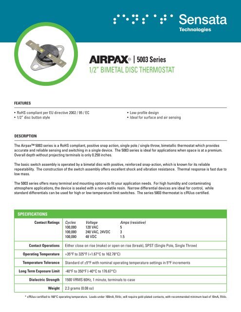
<strong>5003</strong> <strong>Series</strong><br />
1/<strong>2”</strong> <strong>BIMETAL</strong> <strong>DISC</strong> <strong>THERMOSTAT</strong><br />
• Low profile design<br />
• Ideal for surface and air sensing<br />
The <strong>Airpax</strong> <strong>5003</strong> series is a RoHS compliant, positive snap action, single pole / single throw, bimetallic thermostat which provides<br />
accurate and reliable sensing and switching in a single device. The <strong>5003</strong> series is ideal for applications when space is at a premium.<br />
Overall depth without projecting terminals is only 0.250 inches.<br />
The basic switch assembly is operated by a bimetal disc with positive, reinforced snap-action, which is known for its reliable<br />
repeatability. The construction of the switch assembly offers excellent shock and vibration resistance. Thermal response is fast due to<br />
low mass.<br />
The <strong>5003</strong> series offers many terminal and mounting options to fit your application needs. For high humidity and contaminating<br />
atmosphere applications, the device is sealed with a non-volatile resin. Narrow differential devices are ideal for control, while<br />
standard differentials can be used for high or low temperature limit switches. The series <strong>5003</strong> thermostat is cЯUus certified.<br />
SPECIFICATIONS<br />
Contact Ratings Cycles Voltage Amps (resistive)<br />
100,000 120 VAC 5<br />
100,000 240 VAC, 24VDC 3<br />
100,000 48 VDC 1.5<br />
Contact Operations Either close on rise (make) or open on rise (break), SPST (Single Pole, Single Throw)<br />
Operating Temperature +35°F to 325°F (+1.67°C to 162.78°C)<br />
Temperature Tolerance Standard of ±5°F with nominal operating temperature settings in 5°F increments<br />
Long Term Exposure Limit -40°F to 350°F (-40°C to 176.67°C)<br />
Dielectric Strength 1500 VRMS 60Hz, 1 minute, terminals to case<br />
Weight 2.3 grams (0.08 oz)<br />
* cЯUus certified to 168°C operating temperature. Loads under 100mA, 5Vdc, will require gold-plated contacts, with recommended minimum load of 10mA, 5Vdc.
AIRPAX <strong>5003</strong> SERIES DECISION TABLES<br />
1. CONTACT OPERATION<br />
2. TERmINAL SELECTION<br />
A B C D E<br />
F G H J K<br />
L m R U V<br />
NOTES :<br />
CODE DESCRIPTION<br />
(1.22)<br />
0.048<br />
O Letter “O” = Open on Rise<br />
C Letter “C” = Close on Rise<br />
(Ø1.40)<br />
Ø0.055<br />
(9.04)<br />
0.356<br />
(1.98)<br />
0.078<br />
(10.69)<br />
0.421<br />
Same as View "E"<br />
Except Formed 90°<br />
(2.36)<br />
0.093<br />
(1.17)<br />
(6.91) 0.046<br />
0.272 (1.55)<br />
0.061<br />
(3.96)<br />
0.156<br />
(3.96)<br />
0.156<br />
(0.41)<br />
0.016<br />
The standard lead wire<br />
materials for different<br />
temperature ranges are as<br />
follows :<br />
i. Up to 220°F (104.4°C):<br />
#18 stranded UL 1015 AWN<br />
and CSA TEW approved,<br />
black PVC insulation<br />
ii. 221°F to 350°F (105°C to<br />
176.6°C): #18 stranded<br />
black ‘type I’ TFE, Teflon ®<br />
insulation per MIL-W-22759<br />
(1.57)<br />
0.062<br />
(6.35)<br />
0.250<br />
2 Leads<br />
(4.75)<br />
0.187<br />
(Ø1.52)<br />
Ø0.060<br />
(11.43)<br />
0.450<br />
(14.86)<br />
0.585<br />
(152.40 ± 6.35)<br />
6.000 ± 0.250<br />
See notes i & ii for<br />
lead wire specifications<br />
N S W<br />
Same as terminal selection “M”<br />
(304.80 ± 12.70)<br />
Except 2 Leads<br />
12.000 ± 0.500<br />
See notes i & ii for<br />
lead wire specifications<br />
P T (16.13)<br />
Z<br />
Same as terminal selection “M”<br />
(609.60 ± 19.05)<br />
Except 2 Leads<br />
24.000 ± 0.750<br />
See notes i & ii for<br />
lead wire specifications<br />
(3.96)<br />
0.156<br />
(0.41)<br />
0.016<br />
(6.35)<br />
0.250<br />
(3.96)<br />
0.156<br />
(0.51)<br />
0.020<br />
To build your part number (PN), choose the proper codes from pages 2 to 4.<br />
Consult <strong>Sensata</strong> Technologies when a code Z is used to indicate a special<br />
requirement. <strong>Sensata</strong> will assign a unique, customer-specific four digit<br />
nondescript number. To complete the customer specific part number build,<br />
replace the bottom temperature and tolerance (codes 7 & 8) after the “–” dash<br />
with the assigned four digit nondescript.<br />
2 Leads<br />
(1.96)<br />
0.077<br />
(7.24)<br />
0.285<br />
Same as View "B"<br />
Except Formed 90°<br />
(1.98)<br />
0.078<br />
(10.72)<br />
0.422<br />
Same as View "G"<br />
Except Formed 90°<br />
(152.40 ± 6.35)<br />
6.000 ± 0.250<br />
See notes i & ii for<br />
lead wire specifications<br />
Same as terminal selection “R”<br />
(304.80 ± 12.70)<br />
Except 2 Leads<br />
12.000 ± 0.500<br />
See notes i & ii for<br />
lead wire specifications<br />
Same as terminal selection “R”<br />
(609.60 ± 19.05)<br />
Except 2 Leads<br />
24.000 ± 0.750<br />
See notes i & ii for<br />
lead wire specifications<br />
(3.45)<br />
0.136<br />
(7.92)<br />
0.312<br />
(1.22)<br />
0.048<br />
(6.35)<br />
0.250<br />
2 Leads<br />
(7.90)<br />
0.311<br />
(2.36)<br />
0.093<br />
(15.47)<br />
0.609<br />
(7.92)<br />
0.312<br />
White Sleeve<br />
Potted (Sealed)<br />
0.635<br />
(3.96)<br />
0.156<br />
(0.41)<br />
0.016<br />
(3.96)<br />
0.156<br />
(152.40 ± 6.35)<br />
6.000 ± 0.250<br />
See notes i & ii for<br />
lead wire specifications<br />
(0.81)<br />
0.032<br />
(13.84)<br />
0.545<br />
(3.38)<br />
0.133<br />
(2.79 - 2.92)<br />
0.110 - 0.115<br />
(7.11)<br />
0.280<br />
(14.68)<br />
0.578<br />
(11.23)<br />
0.442<br />
(1.98)<br />
0.078<br />
Same as View "J"<br />
Except Formed 90°<br />
(Ø1.22)<br />
Ø0.048<br />
(3.96)<br />
0.156<br />
(0.51)<br />
0.020<br />
Same as terminal selection “U”<br />
(304.80 ± 12.70)<br />
Except 2 Leads<br />
12.000 ± 0.500<br />
See notes i & ii for<br />
lead wire specifications<br />
Same as terminal selection “U”<br />
(609.60 ± 19.05)<br />
Except 2 Leads<br />
24.000 ± 0.750<br />
See notes i & ii for<br />
lead wire specifications<br />
Special<br />
Requirements<br />
Customer<br />
to Specify
EXAmPLE : C53GAB105A-090Y<br />
Close contacts on temperature<br />
rise, <strong>5003</strong> series, 0.25” horizontal<br />
quick-connects with opposed<br />
orientation, 0.140” two hole<br />
mounting bracket, 105°F top<br />
temperature with a ±5°F standard<br />
top tolerance and a standard<br />
15°F differential between top<br />
and bottom temperature for<br />
temperature range of 35°F to<br />
200°F, differential helps calculate<br />
a bottom temperature of 90°F<br />
with a standard minimum reset<br />
for contacts to open at or above<br />
the bottom temperature setpoint.<br />
3. TERmINAL ORIENTATION<br />
A B C Z NOTES :<br />
OPPOSED - Terminals on opposite<br />
sides of thermostat, on a parallel plane<br />
to the mounting bracket / base<br />
PARALLEL - Terminals on same<br />
side of thermostat, on a parallel plane<br />
to the mounting bracket / base<br />
4. mOUNTING AND ENCLOSURE SELECTION<br />
VERTICAL - Both terminals extend<br />
up and away, on a perpendicular plane<br />
to the mounting bracket / base<br />
Special<br />
Requirements<br />
Customer<br />
to Specify<br />
A B C D E<br />
(3.32)<br />
0.131<br />
(7.61)<br />
0.300<br />
(15.39)<br />
0.606<br />
(6.35)<br />
0.250<br />
MAX<br />
(30.15)<br />
1.187<br />
2 Mounting Slots<br />
(3.56) (4.37)<br />
x<br />
0.140 0.172<br />
(16.26)<br />
0.640<br />
(23.01)<br />
0.906<br />
(0.46)<br />
0.018<br />
(30.15)<br />
1.187<br />
(Ø3.55)<br />
Ø0.140<br />
F G H J Z<br />
(21.41)<br />
REF<br />
0.843<br />
(Ø3.73)<br />
Ø0.147<br />
(11.10)<br />
0.437<br />
(3.18)<br />
0.125<br />
(0.46)<br />
0.018<br />
(17.45)<br />
0.687<br />
(34.92)<br />
1.375<br />
1. Contact Operation<br />
* Basic Product <strong>Series</strong><br />
2. Terminal Selection<br />
3. Terminal Orientation<br />
4. Mounting & Enclosure<br />
5. Top Temperature in °F<br />
6. Top Temperature Tolerance Code<br />
7. Bottom Temperature in °F<br />
8. Bottom Temperature Tolerance Code<br />
(0.46)<br />
0.018<br />
(17.45)<br />
0.687<br />
(25.40)<br />
1.000<br />
(Ø3.18)<br />
Ø0.125<br />
(0.79)<br />
0.031<br />
C 53 G A B 1 0 5<br />
(16.26)<br />
0.640<br />
6-32 UNC-2A Thread<br />
(23.80)<br />
0.937<br />
(0.46)<br />
0.018<br />
(10.31)<br />
0.406<br />
(9.52)<br />
0.375<br />
Undercut to Allow Stud<br />
to Screw Down Flat<br />
(30.15)<br />
1.187<br />
(Ø2.76)<br />
Ø0.109<br />
(0.79)<br />
0.031<br />
(16.26)<br />
0.640<br />
8-32 UNC-2A Thread<br />
(23.80)<br />
0.937<br />
(0.46)<br />
0.018<br />
(10.31)<br />
0.406<br />
(9.52)<br />
0.375<br />
Undercut to Allow Stud<br />
to Screw Down Flat<br />
A 0 9 0 Y<br />
Terminal orientation<br />
restrictions :<br />
‘A’ (Opposed) =<br />
A, B, E, G, J, R to T, Z<br />
‘B’ (Parallel) =<br />
A, B, E, R to T, Z<br />
‘C’ (Vertical) =<br />
C, D, F, H, K to P, U to Z<br />
(29.62)<br />
1.166<br />
(Ø3.56)<br />
Ø0.140<br />
(16.26)<br />
0.640<br />
Special<br />
Requirements<br />
Customer<br />
to Specify<br />
(3.56)<br />
0.140<br />
(23.80)<br />
0.937<br />
(0.46)<br />
0.018
5. TOP TEmPERATURE IN °F<br />
°F °C °F °C °F °C<br />
Temperature Setting 35°F to 200°F 1.6°C to 93°C 201°F to 300°F 94°C to 149°C 301°F to 325°F 150°C to 163°C<br />
Standard Tolerance ±5°F ±2.8°C ±8°F ±4.4°C ±10°F ±5.6°C<br />
Nominal Differential 15°F 8.3°C 25°F 13.8°C 30°F 16.7°C<br />
NOTES:<br />
· Select any temperature in the range of 35°F to 325°F. Standard choices fall on the 5°F increments, for example 35°F, 40°F, 45°F, 50°F... up to 320°F or 325°F<br />
· Specify the °F temperature in the part numbering scheme as a three digit code without the ‘°F’ in the part number. For example, for 90°F, put in code ‘090’<br />
6. TOP TEmPERATURE TOLERANCE<br />
CODE A B C X Z<br />
± °F ±5°F ±8°F ±10°F Maximum Customer to Specify<br />
± °C ±2.8°C ±4.4°C ±5.6°C Maximum Customer to Specify<br />
NOTES:<br />
· The standard tolerance for the top temperature is based on the temperature range the top temperature falls in, please refer to “5. Top Temperature in °F” chart,<br />
and select the appropriate code for a standard top temperature tolerance.<br />
7. BOTTOm TEmPERATURE IN °F<br />
“Bottom Temperature in °F” equals the “Top Temperature in °F” minus the “Nominal Differential in °F for that temperature”.<br />
Example 1: 50°F – 15°F = 35°F Example 2: 250°F – 25°F = 225°F Example 3: 310°F – 30°F = 280°F<br />
NOTES:<br />
· Specify the °F temperature in the part numbering scheme as a three digit code without the ‘°F’ in the part number (example 90°F, put in the code as ‘090’)<br />
8. BOTTOm TEmPERATURE TOLERANCE<br />
CODE A B C Y Z<br />
± °F ±5°F ±8°F ±10°F Minimum Customer to Specify<br />
± °C ±2.8°C ±4.4°C ±5.6°C Minimum Customer to Specify<br />
NOTES:<br />
· The typical standard bottom temperature tolerance is a ‘Y’ = minimum trip, which indicates the “reset” trip occurs at or above the lower temperature set point.<br />
· The other standard tolerances are based on the temperature range the bottom temperature is in. The most convenient solution is to use either the ‘Y’ minimum<br />
reset code or choose the same tolerance code selection used in “6. Top Temperature Tolerance Code”.<br />
SENSATA TECHNOLOGIES<br />
529 Pleasant Street<br />
Attleboro, MA 02703-0964 USA<br />
1-508-236-3287 (Main)<br />
1-508-236-1598 (Fax)<br />
http://airpax.sensata.com<br />
http://www.sensata.com<br />
Important Notice: <strong>Sensata</strong> Technologies (<strong>Sensata</strong>) reserves<br />
the right to make changes to or discontinue any product or<br />
service identified in this publication without notice. <strong>Sensata</strong><br />
advises its customers to obtain the latest version of the<br />
relevant information to verify, before placing any orders,<br />
that the information being relied upon is current. <strong>Sensata</strong><br />
assumes no responsibility for infringement of patents or<br />
rights of others based on <strong>Sensata</strong> applications assistance<br />
or product specifications since <strong>Sensata</strong> does not possess<br />
full access concerning the use or application of customers’<br />
products. <strong>Sensata</strong> also assumes no responsibility for<br />
customers’ product designs.<br />
245–500–6010 Printed In U.S.A., August, 2009