SERVICE STATION MANUAL GP 800 ie - Carl Salter
SERVICE STATION MANUAL GP 800 ie - Carl Salter
SERVICE STATION MANUAL GP 800 ie - Carl Salter

Create successful ePaper yourself
Turn your PDF publications into a flip-book with our unique Google optimized e-Paper software.
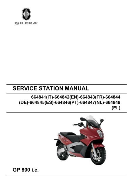
<strong>SERVICE</strong> <strong>STATION</strong> <strong>MANUAL</strong><br />
664841(IT)-664842(EN)-664843(FR)-664844<br />
(DE)-664845(ES)-664846(PT)-664847(NL)-664848<br />
(EL)<br />
<strong>GP</strong> <strong>800</strong> i.e.
<strong>SERVICE</strong> <strong>STATION</strong><br />
<strong>MANUAL</strong><br />
<strong>GP</strong> <strong>800</strong> i.e.<br />
The descriptions and illustrations given in this publication are not binding. While the basic features as<br />
described and illustrated in this manual remain unchanged, PIAGGIO - GILERA reserves the right, at<br />
any time and without being required to update this publication beforehand, to make any changes to<br />
components, parts or accessory suppl<strong>ie</strong>s, which it considers necessary to improve the product or which<br />
are required for manufacturing or construction reasons.<br />
Not all versions shown in this publication are available in all Countr<strong>ie</strong>s. The availability of individual<br />
versions should be confirmed with the official Piaggio sales network.<br />
"© Copyright 2007 - PIAGGIO & C. S.p.A. Pontedera. All rights reserved. Reproduction of this publication<br />
in whole or in part is prohibited."<br />
PIAGGIO & C. S.p.A. - After-Sales<br />
V.le Rinaldo Piaggio, 23 - 56025 PONTEDERA (Pi)
<strong>SERVICE</strong> <strong>STATION</strong> <strong>MANUAL</strong><br />
<strong>GP</strong> <strong>800</strong> i.e.<br />
This service station manual has been drawn up by Piaggio & C. Spa to be used by the workshops of<br />
Piaggio-Gilera dealers. It is assumed that the user of this manual for maintaining and repairing Piaggio<br />
vehicles has a basic knowledge of mechanical principles and vehicle repair technique procedures. Any<br />
significant changes to vehicle characteristics or to specific repair operations will be communicated by<br />
updates to this manual. Nevertheless, no mounting work can be satisfactory if the necessary equipment<br />
and tools are unavailable. It is therefore advisable to read the sections of this manual concerning special<br />
tools, along with the special tool catalogue.<br />
N.B. Provides key information to make the procedure eas<strong>ie</strong>r to understand and carry out.<br />
CAUTION Refers to specific procedures to carry out for preventing damages to the vehicle.<br />
WARNING Refers to specific procedures to carry out to prevent injur<strong>ie</strong>s to the repairer.<br />
Personal safety Failure to completely observe these instructions will result in serious risk of personal<br />
injury.<br />
Safeguarding the environment Sections marked with this symbol indicate the correct use of the vehicle<br />
to prevent damaging the environment.<br />
Vehicle intactness The incomplete or non-observance of these regulations leads to the risk of serious<br />
damage to the vehicle and sometimes even the invalidity of the guarantee.
INDEX OF TOPICS<br />
CHARACTERISTICS CHAR<br />
TOOLING TOOL<br />
MAINTENANCE MAIN<br />
TROUBLESHOOTING TROUBL<br />
ELECTRICAL SYSTEM ELE SYS<br />
ENGINE FROM VEHICLE ENG VE<br />
ENGINE ENG<br />
INJECTION INJEC<br />
SUSPENSIONS SUSP<br />
BRAKING SYSTEM BRAK SYS<br />
COOLING SYSTEM COOL SYS<br />
CHASSIS CHAS<br />
PRE-DELIVERY PRE DE<br />
TIME TIME
INDEX OF TOPICS<br />
CHARACTERISTICS CHAR
Characteristics <strong>GP</strong> <strong>800</strong> i.e.<br />
This section describes the general specifications of the vehicle.<br />
Rules<br />
This section describes general safety rules for any maintenance operations performed on the vehicle.<br />
Safety rules<br />
- If work can only be done on the vehicle with the engine running, make sure that the premises are well-<br />
ventilated, using special extractors if necessary; never let the engine run in an enclosed area. Exhaust<br />
fumes are toxic.<br />
- The battery electrolyte contains sulphuric acid. Protect your eyes, clothes and skin. Sulphuric acid is<br />
highly corrosive; in the event of contact with your eyes or skin, rinse thoroughly with abundant water<br />
and seek immediate medical attention.<br />
- The battery produces hydrogen, a gas that can be highly explosive. Do not smoke and avoid sparks<br />
or flames near the battery, especially when charging it.<br />
- Fuel is highly flammable and it can be explosive given some conditions. Do not smoke in the working<br />
area, and avoid open flames or sparks.<br />
- Clean the brake pads in a well-ventilated area, directing the jet of compressed air in such a way that<br />
you do not breathe in the dust produced by the wear of the friction material. Even though the latter<br />
contains no asbestos, inhaling dust is harmful.<br />
Maintenance rules<br />
- Use original PIAGGIO spare parts and lubricants recommended by the Manufacturer. Non-original or<br />
non-conforming spares may damage the vehicle.<br />
- Use only the appropriate tools designed for this vehicle.<br />
- Always use new gaskets, sealing rings and split pins upon refitting.<br />
- After removal, clean the components using non-flammable or low flash-point solvent. Lubricate all the<br />
work surfaces except the tapered couplings before refitting.<br />
- After refitting, make sure that all the components have been installed correctly and work properly.<br />
- For removal, overhaul and refit operations use only tools with metric measures. Metric bolts, nuts and<br />
screws are not interchangeable with coupling members with English measurement. Using unsuitable<br />
coupling members and tools may damage the scooter.<br />
- When carrying out maintenance operations on the vehicle that involve the electrical system, make<br />
sure the electric connections have been made properly, particularly the ground and battery connections.<br />
CHAR - 2
<strong>GP</strong> <strong>800</strong> i.e. Characteristics<br />
Vehicle identification<br />
Chassis prefix (A):<br />
ZAPM55100<br />
Engine prefix (B):<br />
M554M<br />
Dimensions and mass<br />
CHAR - 3
Characteristics <strong>GP</strong> <strong>800</strong> i.e.<br />
Engine<br />
WEIGHTS AND DIMENSIONS<br />
Specification Desc./Quantity<br />
Kerb weight 248 ± 10 kg<br />
Maximum weight allowed 450 kg<br />
Maximum height 1300 ÷ 1370 mm<br />
Width 790 mm<br />
Wheelbase 1585 mm<br />
Length 2230 mm<br />
ENGINE<br />
Specification Desc./Quantity<br />
Type 90° V-twin engine, 4-stroke, with double spark plug<br />
Cubic capacity 839 cm3<br />
Bore x stroke 88 x 69 mm<br />
Compression ratio 10.5 ± 0.5 : 1<br />
Engine idle speed 1,250 ± 100 rpm<br />
Timing system 4 valves, single overhead camshaft, driven.<br />
Valve clearance Inlet: 0.15 mm<br />
Outlet: 0.15 mm<br />
MAX. Power 50.5 kW at 7,750 rpm<br />
MAX. torque 71 Nm at 4,500 rpm<br />
Lubrication Engine lubrication by a dry sump system, with<br />
double lobe pump (one for delivery and one for return),<br />
controlled by a chain and paper filter.<br />
Lubrication pressure 3.5 ÷ 4 bar<br />
Minimum lubrication pressure (100° C) 0.8 bar<br />
Fuel supply Multipoint electronic injection with single Ø 38-mm<br />
throttle body and electric fuel pump.<br />
Cooling Forced liquid circulation cooling.<br />
Fuel Unleaded petrol (95 RON)<br />
TECHNICAL SPECIFICATIONS<br />
CHAR - 4<br />
OIL PUMP<br />
Specification Desc./Quantity<br />
Type Trochoidal<br />
Rotor washers Delivery pump: 12 mm<br />
Scavenge pump: 22 mm<br />
Assembly clearances Lobe ends: 0.04 ÷ 0.1 mm<br />
External rotor radial clearance 0.05- 0.12 mm<br />
Levelness 0.1 mm<br />
BY-PASS<br />
Specification Desc./Quantity<br />
Type with piston<br />
Plunger diameter Ø 14-0.016 -0.043 mm<br />
Unloaded spring length 52 mm<br />
Calibration pressure 4.5 bar
<strong>GP</strong> <strong>800</strong> i.e. Characteristics<br />
* Tightening torque 5÷7 N·m<br />
OIL FILTER<br />
Specification Desc./Quantity<br />
Type Paper with pressure rel<strong>ie</strong>f and anti-drain back bypass<br />
valves<br />
OIL MINIMUM PRESSURE INDICATOR LIGHT SWITCH<br />
Specification Desc./Quantity<br />
Calibration 0.3 - 0.6 bar<br />
HEAD LUBRICATION CONTROL JET<br />
Specification Desc./Quantity<br />
Diameter 1 ± 0.05 mm *<br />
PISTON COOLING NOZZLE<br />
Specification Desc./Quantity<br />
Diameter Ø 1 ± 0.05 mm<br />
CRANKCASE VENTILATION CHECK<br />
Specification Desc./Quantity<br />
Device metal reed valve and decantation chamber<br />
TECHNICAL SPECIFICATIONS<br />
Specification Desc./Quantity<br />
Cooling system capacity 2.4 l<br />
Prescribed fluid AGIP PERMANENT SPEZIAL<br />
Sealing pressure Cap calibrated at 0.9 bar<br />
THERMOSTAT<br />
Specification Desc./Quantity<br />
Type Wax-type, with deviator<br />
Starts opening 85±2°C<br />
ELECTRIC VENTILATION<br />
Specification Desc./Quantity<br />
Type With piston<br />
Electric ventilation starts at 105°C<br />
Electric ventilation stops at 100°C<br />
WATER PUMP<br />
Specification Desc./Quantity<br />
Type Centrifugal<br />
Control Gear on oil delivery pump<br />
RADIATOR<br />
Specification Desc./Quantity<br />
Type Aluminium, with horizontal circulation<br />
CHAR - 5
Characteristics <strong>GP</strong> <strong>800</strong> i.e.<br />
Transmission<br />
Capacit<strong>ie</strong>s<br />
Electrical system<br />
EXPANSION TANK<br />
Specification Desc./Quantity<br />
Calibration Automatic bleeding, in parallel with the radiator<br />
TRANSMISSION<br />
Specification Desc./Quantity<br />
Main drive Automatic expandable pulley variator with torque<br />
server, V-belt, automatic dry self-ventilating<br />
clutch.<br />
Secondary reduction Gear reduction unit in oil bath.<br />
Final transmission Chain-driven<br />
CAPACITY<br />
Specification Desc./Quantity<br />
Engine oil 2.5 l (without oil filter replacement)<br />
2.6 l (with oil filter replacement)<br />
Transmission oil ~ ----- cm³<br />
Cooling system fluid ~ 2.4 l<br />
Fuel tank (reserve) ~14 l ± 0.5 l (~1.8 l)<br />
ELECTRICAL SYSTEM<br />
Specification Desc./Quantity<br />
Start-up Electric<br />
Ignition High effic<strong>ie</strong>ncy electronic inductive ignition, integrated<br />
with the injection system, with variable advance<br />
and separate HV coil.<br />
Ignition advance Three-dimensional map managed by control unit<br />
Spark plug NGK CR7EKB<br />
Alternative spark plug -<br />
Battery 12 V / 14 Ah, SEALED BATTERY<br />
Generator Three-phase alternating current, 450W.<br />
There are two types of remote controls in the elec-<br />
trical system, those operating as "circuit breakers"<br />
«A», and those operating as a "switches" «B».<br />
CHAR - 6
<strong>GP</strong> <strong>800</strong> i.e. Characteristics<br />
CHECKING REMOTE CONTROLS «A» OPER-<br />
ATING AS CIRCUIT BREAKERS<br />
1) Check that, given regular conditions, there is no<br />
continuity between terminals 30 and 87.<br />
2) Apply 12V voltage to power terminals 85 and 86<br />
of the remote control.<br />
3) With the remote control powered, check that<br />
there is continuity between terminals 30 and 87.<br />
4) If these conditions are not fulfilled, the remote<br />
control is damaged and must be replaced.<br />
CHECKING REMOTE CONTROLS «B» OPER-<br />
ATING AS SWITCHES<br />
1) Check that, given regular conditions, there is no<br />
continuity between terminals 30 and 87 but that<br />
there is continuity between terminals 30 and 87a.<br />
2) Apply 12V voltage to power terminals 85 and 86<br />
of the remote control.<br />
3) With the remote control powered, check that<br />
there is continuity between terminals 30 and 87.<br />
However, there must be no continuity between ter-<br />
minals 30 and 87a.<br />
4) If these conditions are not fulfilled, the remote<br />
control is damaged and must be replaced.<br />
To check buttons and switches make sure that, according to their position, the continuity of contacts is<br />
correct, as indicated in the following tables.<br />
«MODE» BUTTON<br />
CHAR - 7
Characteristics <strong>GP</strong> <strong>800</strong> i.e.<br />
WINDSHIELD «UP» BUTTON<br />
WINDSHIELD «DOWN» BUTTON<br />
HELMET COMPARTMENT LIGHT BUTTON<br />
HORN BUTTON<br />
CHAR - 8
<strong>GP</strong> <strong>800</strong> i.e. Characteristics<br />
STARTER BUTTON<br />
LIGHT SWITCH<br />
ENGINE STOP SWITCH<br />
TURN INDICATOR SWITCH<br />
CHAR - 9
Characteristics <strong>GP</strong> <strong>800</strong> i.e.<br />
INTAKE AIR TEMPERATURE SENSOR<br />
-10° = 9600 Ohm<br />
0° = 5900 Ohm<br />
+10° = 3<strong>800</strong> Ohm<br />
+20° = 2500 Ohm<br />
-30° = 1700 Ohm<br />
THROTTLE POSITION SENSOR<br />
With the switch set to "ON" at a variable voltage<br />
between 0.7V and > 4V between pins 23 - 3 on<br />
engine-side wiring.<br />
Ground insulation of pins 29 - 32 - 3 on engine-side<br />
wiring<br />
STEPPER MOTOR<br />
Resistance engine-side connector between pins<br />
19 - 9 ~ 51 Ohm<br />
Resistance engine-side connector between pins<br />
18 - 17 ~ 51 Ohm<br />
FUEL INJECTOR<br />
Type: 4 holes<br />
Conicity of the nozzle: 24°<br />
Resistance at terminals: 13.7 ÷ 15.2 Ohm<br />
CHAR - 10
<strong>GP</strong> <strong>800</strong> i.e. Characteristics<br />
FUEL PUMP UNIT<br />
Mechanical type pressure regulator operating at a<br />
pressure of 3 BAR<br />
Pump winding resistance: ~ 1,5 Ohm<br />
REVOLUTION TIMING SENSOR<br />
Resistance between "+ and -" = 890 ± Ohm (pins<br />
35 - 25 , engine-side wiring)<br />
Insulation between "+ and S" and between "- and<br />
S" (pins 35 - 34 and 25 - 34, engine-side wiring)<br />
ENGINE TEMPERATURE SENSOR<br />
0° = 5900 Ohm<br />
+10° = 3<strong>800</strong> Ohm<br />
+20° = 2500 Ohm<br />
+30° = 1700 Ohm<br />
+80° = 300 Ohm<br />
H.V. COIL<br />
Primary winding resistance: 520 ÷ 620 mOhm<br />
Secondary resistance: 6830 ÷ 7830 Ohm<br />
CHAR - 11
Characteristics <strong>GP</strong> <strong>800</strong> i.e.<br />
MINIMUM OIL PRESSURE SENSOR<br />
Normally closed switch<br />
Activation threshold: 0.3 - 0.6 bar<br />
With the engine off: continuity between terminal<br />
and ground<br />
STATOR<br />
Resistance between terminals: 0.2 ÷ 1 Ohm<br />
Terminal insulation from ground<br />
Frame and suspensions<br />
Brakes<br />
CHAR - 12<br />
FRAME AND SUSPENSIONS<br />
Specification Desc./Quantity<br />
Chassis Double cradle with tubular and steel stamped<br />
plates<br />
Front suspension Hydraulic telescopic fork, single plate, ø 41-mm<br />
straight stems.<br />
Front suspension travel 126 mm<br />
Oil quantity for stem 295 ± 3 cm³<br />
Unloaded spring length ----- mm<br />
Rear suspension Single shock absorber that acts directly on the<br />
fork.<br />
Rear suspension travel 135 mm<br />
BRAKES<br />
Specification Desc./Quantity<br />
Front brake Ø 300-mm double disc brake with hydraulic control<br />
activated by the handlebar right-hand lever.<br />
Two floating callipers, ø 28 double plunger<br />
Rear brake Ø 280-mm disc brake, with hydraulic servo operated<br />
from the handlebar with the left-hand lever.<br />
One floating calliper with a single plunger
<strong>GP</strong> <strong>800</strong> i.e. Characteristics<br />
Wheels and tyres<br />
WHEELS AND TYRES<br />
Specification Desc./Quantity<br />
Wheel rim type Light alloy rims.<br />
Front rim 16'' x 3.50<br />
Rear rim 15'' x 4.50<br />
Front tyre Tubeless, 120/70 - 16" 57H<br />
Rear tyre Tubeless, 160/60 - 15" 67H<br />
Front tyre pressure (with passenger) 2.5 bar (-)<br />
Rear tyre pressure (with passenger) 2.75 bar (-)<br />
Tightening Torques<br />
LUBRICATION<br />
Name Torque in Nm<br />
Engine oil drainage plug 21 ÷ 29<br />
Bulkhead screws for oil pump housing cover 3 ÷ 4<br />
Engine oil filter 12 - 16<br />
Oil pump chain tensioner pad 2 ÷ 3<br />
Oil pump screws 5 - 6<br />
By-pass scavenge duct fixing screws 11 ÷ 13<br />
Lubrication circuit upper bulkhead 3 ÷ 4<br />
Oil pump crown screw 10 ÷ 14<br />
Screws fixing oil pump to the crankcase 5 - 6<br />
Minimum oil pressure sensor 10<br />
Water pump gear fixing screw 5 - 6<br />
THERMAL GROUP AND TIMING SYSTEM<br />
Name Torque in Nm<br />
Spark plug 12 ÷ 14<br />
Head fixing stud bolts: ***<br />
Head fixing nuts 10 - 12<br />
Exhaust / intake head fixing nuts: 10 - 12<br />
Head lubrication control jet 5 - 7<br />
Tensioner sliding block fixing screw: 10 - 14<br />
injector fixing screw 3 ÷ 4<br />
inlet manifold fixing screws 11 - 13<br />
Tappet cover fixing screws: 7 - 9<br />
Throttle body fixing screws 11 ÷ 13<br />
camshaft retaining bracket fixing screws 4 - 6<br />
Head fixing screws 10 - 12<br />
Coolant temperature sensor 21 ÷ 23<br />
Revolution timing sensor fixing screw 7.5 ÷ 8.5<br />
Timing system chain tensioner screw 11 ÷ 13<br />
Timing system gear on camshaft screw 12 ÷ 14<br />
*** Apply a preliminary torque of 10 Nm in a criss-crossed sequence. - tighten with a torque of 13 Nm<br />
+ 90° in a criss-crossed sequence. - tighten again by 90° in a criss-crossed sequence.<br />
TRANSMISSION COVER<br />
Name Torque in Nm<br />
Drive pulley nut 252 ÷ 278<br />
CHAR - 13
Characteristics <strong>GP</strong> <strong>800</strong> i.e.<br />
Name Torque in Nm<br />
Driven pulley nut 153 ÷ 187<br />
Clutch ring nut 65 - 75<br />
External transmission cover screws 5 ÷ 7<br />
Internal transmission cover screws 11 ÷ 13<br />
Air switch screw 3 ÷ 4<br />
Air outlet grille screws 3 ÷ 4<br />
FLYWHEEL COVER<br />
Name Torque in Nm<br />
Flywheel fixing nut 116 ÷ 128<br />
Stator retainers 8 - 10<br />
Screw fixing freewheel to flywheel 13 ÷ 15<br />
Flywheel cover screws 11 - 13<br />
CRANKCASE AND CRANKSHAFT<br />
Name Torque in Nm<br />
Starting ring gear retaining plate 3 ÷ 4<br />
Engine crankcase coupling screws (M6) 11 ÷ 13<br />
Engine crankcase coupling screws (M8) 25 ÷ 28<br />
COOLING<br />
Name Torque in Nm<br />
Water pump rotor cover 3 ÷ 4<br />
bleed screw 3 ÷ 4<br />
Water pump impeller 4 ÷ 5<br />
Screws tightening water pump gear protection<br />
plate<br />
3 ÷ 4<br />
CHASSIS<br />
Name Torque in Nm<br />
Side stand bolt nut 37<br />
Screws fixing side stand button 6<br />
Screw fixing electric fan - radiator 2 ÷ 3<br />
Screw fixing radiator - chassis 5 ÷ 7<br />
Nut fixing silent-block plate - chassis 22 ÷ 25<br />
Nut fixing silent-block plate 33 ÷ 41<br />
Pin fixing nut - M14 124 ÷ 153<br />
Pin fixing nut - M10 47 ÷ 52<br />
Upper nut fixing engine support link rods - chassis 33 ÷ 41<br />
Lower nut fixing engine support link rods - chassis 33 ÷ 41<br />
Nut fixing head - exhaust manifold 16 ÷ 18<br />
Centre stand front bolt nut 34 ÷ 39<br />
Centre stand rear bolt nut 74 ÷ 81<br />
Screw fixing silencer - muffler support arm 11<br />
Screw fixing catalytic converter - catalytic convert-<br />
22 ÷ 24<br />
er support<br />
Screw fixing muffler support arm - engine 24 ÷ 27<br />
Silencer fixing screw 22<br />
Manifold retainer clamp 16 ÷ 18<br />
CHAR - 14
<strong>GP</strong> <strong>800</strong> i.e. Characteristics<br />
PINION UNIT<br />
Name Torque in Nm<br />
Screw for plate locking pinion driving bushing 4 ÷ 6*<br />
Screws fixing pinion unit cover 4 ÷ 5*<br />
Screws fixing pinion unit - chassis 50<br />
Pinion unit oil drain screw 13 ÷ 15<br />
Pinion unit oil filling screw 13 ÷ 15<br />
Oil sealing casing clamp 3 ÷ 5<br />
(*) Apply LOCTITE 243 threadlock<br />
HANDLEBAR<br />
Name Torque in Nm<br />
Screws fixing handlebar supporting plate - steering<br />
tube<br />
50 ÷ 55<br />
Screws fixing frame - supporting plate 4.5 ÷ 7<br />
Screws fixing half-handlebars - supporting plate 20 ÷ 25*<br />
Screw fixing half-handlebar insert - half-handlebar 20 ÷ 25*<br />
Handlebar cover fixing screw 2.5 ÷ 4<br />
Brake pump stand fixing screws 7 ÷ 10<br />
(*) Apply LOCTITE 243 threadlock<br />
MISCELLANEOUS<br />
Name Torque in Nm<br />
starter motor retainers 11 - 13<br />
BRAKE SYSTEM<br />
Name Torque in Nm<br />
Brake pipes / rear brake calliper coupling 20 ÷ 25<br />
Brake pipes / brake pump coupling 16 ÷ 20<br />
Screws fixing front brake disc to rim 25<br />
Screws fixing rear brake disc to rim 25<br />
Screws fixing brake pump to handlebar 7 ÷ 10<br />
Screw fixing three-way union to fork head 10 ÷ 12<br />
Screws fixing front brake calliper to fork 20 ÷ 25<br />
Screw fixing rear brake calliper to supporting plate 20 ÷ 25<br />
Screw fixing parking brake calliper to supporting<br />
24 ÷ 27<br />
plate<br />
Brake calliper bleed screw 4 ÷ 7<br />
Parking brake adjusting nut 10<br />
Nut fixing rear brake pipe retaining clip 11 ÷ 13<br />
Pin fixing parking brake pads 15 ÷ 20<br />
Brake pipes / three-way union coupling 18 ÷ 23<br />
Brake pipes / front brake calliper coupling 16 ÷ 20<br />
Rear brake pad fixing pins 15 ÷ 20<br />
FRONT SUSPENSION<br />
Name Torque in Nm<br />
Screw fixing wheel pin on right fork leg 6 ÷ 7<br />
Front wheel pin nut 60 ÷ 70<br />
Hydraulic rod fixing screw 25 ÷ 35*<br />
Fork locking screws cap 35 - 55<br />
Stem support clamp tightening screws 20 ÷ 25<br />
CHAR - 15
Characteristics <strong>GP</strong> <strong>800</strong> i.e.<br />
Name Torque in Nm<br />
Steering tube lower ring nut 20 ÷ 22<br />
Steering tube upper ring nut 48 ÷ 54<br />
(*) Apply LOCTITE 243 threadlock<br />
REAR SUSPENSION<br />
Name Torque in Nm<br />
Nut fixing shock absorber - fork 38 - 46<br />
Screw fixing shock absorber - fork 38 - 46<br />
Screw fixing chain stop slider - fork 5 ÷ 7<br />
Screw fixing centre stand stop buffer - fork 5 ÷ 7<br />
Crown fixing screws 22.5 ÷ 27.5*<br />
Rear wheel pin nut 70<br />
Fork locking ring nut 60 ± 3 Nm<br />
Fork pin set screw 0.5<br />
Fork pin nut 90 ± 5<br />
(*) Apply LOCTITE 243 threadlock<br />
Overhaul data<br />
Assembly clearances<br />
Cylinder - piston assy.<br />
CHAR - 16
<strong>GP</strong> <strong>800</strong> i.e. Characteristics<br />
HEIGHT TO MEASURE THE PISTON<br />
Specification Desc./Quantity<br />
A 10 mm<br />
B 43 mm<br />
CYLINDER - PISTON<br />
Specification Desc./Quantity<br />
Cylinder diameter C 88 +0.018-0.01 mm<br />
Piston Ø P 87.968 ±0.014 mm<br />
COUPLING CATEGORIES<br />
Name Initials Cylinder Piston Play on fitting<br />
Cylinder- Piston A 87.990÷87.997 87.954÷87.961 0.029÷0.043<br />
Cylinder- Piston B 87.997 ÷ 87.004 87.961 ÷ 87.968 0.029÷0.043<br />
Cylinder- Piston C 88.004÷88.011 87.968÷87.975 0.029÷0.043<br />
Cylinder- Piston D 88.011÷88.018 87.975 ÷ 87.982 0.029÷0.043<br />
N.B.<br />
THE PISTON MUST BE INSTALLED WITH THE ARROW FACING TOWARDS THE EXHAUST SIDE,<br />
THE PISTON RINGS MUST BE INSTALLED WITH THE WORD «TOP» OR THE STAMPED MARK<br />
FACING UPWARDS.<br />
- Calculate the coupling clearance between pin<br />
and connecting rod end.<br />
Characteristic<br />
Standard clearance:<br />
0.015 ÷ 0.029 mm<br />
- Measure the capacity diameter on the piston.<br />
Characteristic<br />
Standard diameter:<br />
22 + 0.006 + 0.001 mm<br />
- Calculate the piston pin coupling clearance.<br />
N.B.<br />
THE PIN HOUSINGS HAVE 2 LUBRICATION CHANNELS. FOR THIS REASON, MEASUREMENT<br />
MUST BE MADE ACCORDING TO THE PISTON AXIS.<br />
Characteristic<br />
Standard clearance:<br />
0.001 ÷ 0.010 mm<br />
CHAR - 17
Characteristics <strong>GP</strong> <strong>800</strong> i.e.<br />
- Check that coating is free from flakes.<br />
- Check that the head matching surface exhibits no<br />
deformations or wear.<br />
Characteristic<br />
Maximum allowable run-out:<br />
0.05 mm<br />
- Pistons and cylinders are classif<strong>ie</strong>d into categor<strong>ie</strong>s based on their diameter. The coupling is carr<strong>ie</strong>d<br />
out in pairs (A-A, B-B, C-C, D-D).<br />
Piston rings<br />
*Fit rings «2» and «3» with the word «TOP» facing upwards.<br />
** Position the openings in the rings as shown here.<br />
***Value «A» of sealing ring inside the cylinder.<br />
Check the size of the sealing ring opening:<br />
Compression ring: 0.15 ÷ 0.35 mm. Max. value 0.5 mm<br />
Oil scraper ring: 0.25 ÷ 0.50 mm. Max. value 0.65 mm<br />
Oil scraper ring: 0.25 ÷ 0.50 mm. Max. value 0.65 mm<br />
CHAR - 18
<strong>GP</strong> <strong>800</strong> i.e. Characteristics<br />
Rings/housing coupling clearances:<br />
Carefully clean the sealing ring housings.<br />
Place a thickness gauge between the ring and the<br />
housing as shown in the drawing and check the<br />
coupling clearances.<br />
Top ring Standard coupling clearance:<br />
0.01÷0.06 mm<br />
Maximum clearances allowed after use: 0.10<br />
mm<br />
Intermediate ring Standard coupling clear-<br />
ance:0.02÷0.07 mm<br />
Maximum clearances allowed after use: 0.10<br />
mm<br />
Oil scraper ring Standard coupling clearance:<br />
0.01÷0.06 mm<br />
Maximum clearances allowed after use: 0.10<br />
mm<br />
Replace the piston if clearances exceed the max-<br />
imum limits specif<strong>ie</strong>d in the table.<br />
Crankcase - crankshaft - connecting rod<br />
Diameter of crankshaft bearings.<br />
Measure the capacity on both axes x-y.<br />
CHAR - 19
Characteristics <strong>GP</strong> <strong>800</strong> i.e.<br />
Crankshaft alignment<br />
Specific tooling<br />
CRANKSHAFT<br />
Specification Desc./Quantity<br />
Cat. 1 Standard diameter: 45.010 ÷ 45.016<br />
Cat. 2 Standard diameter: 45.016 ÷ 45.022<br />
020335Y Magnetic support for dial gauge<br />
CHAR - 20<br />
MAX. ADMISSIBLE DISPLACEMENT<br />
Specification Desc./Quantity<br />
A = 0.15 mm<br />
B = 0.010 mm<br />
C = 0.010 mm<br />
D = 0.10 mm
<strong>GP</strong> <strong>800</strong> i.e. Characteristics<br />
AXIAL CLEARANCE BETWEEN CRANKSHAFT AND CONNECTING ROD<br />
Name Description Dimensions Initials Quantity<br />
Half-shaft, transmission<br />
side<br />
23.8 +0.1 A D = 0.20 ÷ 0.55<br />
Flywheel-side halfshaft<br />
23.8 + 0.1 B D = 0.20 ÷ 0.55<br />
Connecting rod 22 -0.10 - 0.15 C D = 0.20 ÷ 0.55<br />
Complete crankshaft<br />
91.8 +0.05 E D = 0.20 ÷ 0.55<br />
Characteristic<br />
Crankshaft-crankcase axial clearance (H)<br />
CHAR - 21
Characteristics <strong>GP</strong> <strong>800</strong> i.e.<br />
0.1 ÷ 0.45 mm (when cold)<br />
- Using a bore gauge, measure the connecting rod<br />
small end diameter.<br />
N.B.<br />
IF THE CONNECTING ROD SMALL END DIAM-<br />
ETER EXCEEDS THE STANDARD DIAMETER,<br />
EXHIBITS WEAR OR OVERHEATING, PRO-<br />
CEED TO REPLACE THE CRANKSHAFT AS<br />
DESCRIBED IN CHAPTER CRANKCASE AND<br />
CRANKSHAFT.<br />
Characteristic<br />
Standard diameter:<br />
22 + 0.025 +0.015 mm<br />
- Check the inside diameter of the main bushings<br />
in the three directions indicated in the diagram.<br />
- Repeat the measurements for the other bushing<br />
half. see diagram.<br />
N.B.<br />
DO NOT TAKE THE MEASUREMENT ON THE<br />
TWO HALF-SHELL COUPLING SURFACE<br />
SINCE THE ENDS ARE RELIEVED TO ALLOW<br />
BENDING DURING THE DRIVING OPERATION.<br />
Before assembling, check that the clearance between the engine crankcase bushing and the crankshaft<br />
is within the predetermined limits.<br />
Characteristic<br />
Crankshaft-bushing maximum clearance admitted:<br />
0.08 mm<br />
- The standard bushing diameter after driving is variable on the basis of a coupling selection.<br />
- The bushing seats in the crankcase and the crankshaft are classif<strong>ie</strong>d into 2 categor<strong>ie</strong>s.<br />
- Bushings are subdivided into 3 categor<strong>ie</strong>s according to their thickness (see the table).<br />
The following kinds of bushings indicated in the table must be used according to the kind of coupling<br />
between the crankshaft and the crankcase.<br />
CHAR - 22
<strong>GP</strong> <strong>800</strong> i.e. Characteristics<br />
KEY<br />
X = Crankshaft category<br />
Y = Crankcase half-shell category<br />
A = Red<br />
B = Blue<br />
C = Yellow<br />
Cylinder Head<br />
Before performing head service operations, thoroughly clean all coupling surfaces. Note the position of<br />
the springs and the valves so as not to change the original position during refitting<br />
- Using a trued bar and feeler gauge check that the<br />
cylinder head surface is not worn or distorted.<br />
Characteristic<br />
Maximum allowable run-out:<br />
0.1 mm<br />
- In case of irregularit<strong>ie</strong>s, replace the head.<br />
- Check the sealing surfaces for the intake and exhaust manifold.<br />
- Check that the camshaft and the rocker pin capacit<strong>ie</strong>s exhibit no wear.<br />
- Check that the head cover surface is not worn.<br />
- Check that the coolant sealing pad exhibits no oxidation.<br />
CHAR - 23
Characteristics <strong>GP</strong> <strong>800</strong> i.e.<br />
- Insert the valves into the cylinder head.<br />
- Alternatively check the intake and exhaust<br />
valves.<br />
- The test is carr<strong>ie</strong>d out by filling the manifold with<br />
petrol and checking that the head does not ooze<br />
through the valves when these are just pressed<br />
with the fingers.<br />
Measure the camshaft bearing seats and rocking<br />
lever support pins with a bore meter<br />
HEAD BEARINGS<br />
Specification Desc./Quantity<br />
Bearing "A" 42 +0.025<br />
Bearing "B" 19.5 -0.2<br />
Bearing "C" 13 +0.018<br />
- Measure the unloaded spring length.<br />
Characteristic<br />
Standard length:<br />
44.4 mm<br />
Admissible limit after use:<br />
42.4 mm<br />
CHAR - 24
<strong>GP</strong> <strong>800</strong> i.e. Characteristics<br />
- Clean the valve seats of any carbon residues.<br />
- Using the Prussian blue, check the width of the<br />
impression on the valve seat "V".<br />
Characteristic<br />
Standard value:<br />
1 - 1.3 mm<br />
Admissible limit:<br />
1.6 mm<br />
- If the impression width on the valve seat is larger than the prescribed limits, true the seats with a 45°<br />
mill and then grind.<br />
- In case of excessive wear or damages, replace the head.<br />
STANDARD VALVE LENGTH<br />
Specification Desc./Quantity<br />
Inlet: 95.0 ± 0.3 mm<br />
Outlet: 94.2 ± 0.3 mm<br />
- Measure the diameter of the valve stems in the three positions indicated in the diagram.<br />
STANDARD DIAMETER<br />
Specification Desc./Quantity<br />
Inlet: 4.987 - 4.972 mm<br />
Outlet: 4.975 - 4.960 mm<br />
MINIMUM ADMISSIBLE DIAMETER<br />
Specification Desc./Quantity<br />
Inlet: 4.96 mm<br />
Outlet: 4.945 mm<br />
CHAR - 25
Characteristics <strong>GP</strong> <strong>800</strong> i.e.<br />
- Calculate the clearance between valve and valve<br />
guide.<br />
- Check the deviation of the valve stem by resting<br />
it on a "V" shaped abutment and measuring the<br />
extent of the deformation with a comparator.<br />
Characteristic<br />
Limit values admitted:<br />
0.1 mm<br />
- Check the concentricity of the valve head by ar-<br />
ranging a comparator at right angle relative to the<br />
valve head and rotate it on a "V" shaped abutment.<br />
Characteristic<br />
Admissible limit:<br />
0.03 mm<br />
Measure the valve guide.<br />
Characteristic<br />
Valve guide:<br />
5 +0.012 mm<br />
CHAR - 26
<strong>GP</strong> <strong>800</strong> i.e. Characteristics<br />
- After measuring the valve guide diameter and the<br />
valve stem diameter, check the clearance be-<br />
tween guide and stem.<br />
OUTLET<br />
Specification Desc./Quantity<br />
Standard clearance: 0.025 ÷ 0.052 mm<br />
Admissible limit: 0.09 mm<br />
INLET<br />
Specification Desc./Quantity<br />
Standard clearance: 0.013 - 0.04 mm<br />
Admissible limit: 0.08 mm<br />
- Check that there are no signs of wear on the surface of contact with the articulated register terminal.<br />
- If the checks above give no failures, you can use<br />
the same valves. To obtain better sealing perform-<br />
ance, grind the valve seats. Grind the valves gently<br />
with a fine-grained lapping compound. During the<br />
grinding, keep the cylinder head with the valve ax-<br />
es in a horizontal position. This will prevent the<br />
lapping compound residues from penetrating be-<br />
tween the valve stem and the guide (see figure).<br />
CAUTION<br />
TO AVOID SCORING THE CONTACT SURFACE, DO NOT KEEP ROTATING THE VALVE WHEN<br />
NO LAPPING COMPOUND IS LEFT. CAREFULLY WASH THE CYLINDER HEAD AND THE<br />
VALVES WITH A SUITABLE PRODUCT FOR THE TYPE OF LAPPING COMPOUND BEING USED.<br />
CAUTION<br />
CHAR - 27
Characteristics <strong>GP</strong> <strong>800</strong> i.e.<br />
DO NOT REVERSE THE FITTING POSITIONS OF THE VALVES (RIGHT - LEFT).<br />
- Check that the camshaft ends exhibit no scores or irregular wear.<br />
- Using a micrometer, measure the camshaft capacity.<br />
STANDARD DIAMETER<br />
Specification Desc./Quantity<br />
Bearing A Ø: 42 - 0.060 -0.085 mm<br />
Bearing B diameter: 20 - 0.020 -0.041 mm<br />
MINIMUM ADMISSIBLE DIAMETER<br />
Specification Desc./Quantity<br />
Bearing A Ø: 41.910 mm<br />
Bearing B diameter: 19.940 mm<br />
-Using a gauge, measure the cam height.<br />
STANDARD HEIGHT<br />
Specification Desc./Quantity<br />
intake 33.988 mm<br />
discharge 33.417 mm<br />
ADMISSIBLE LIMITS<br />
Specification Desc./Quantity<br />
intake 33.740 mm<br />
discharge 33.170 mm<br />
Standard axial clearance: 0 - 0.22 mm<br />
Maximum admissible axial clearance: 0.3 mm<br />
- Check that the cam contact sliding block and the articulated register plate is free from wear.<br />
- In case of wear, replace the component.<br />
CHAR - 28
<strong>GP</strong> <strong>800</strong> i.e. Characteristics<br />
- Check that the rocking lever pins exhibit no scores or wear.<br />
Characteristic<br />
Standard diameter:<br />
13 - 0.010 -0.018 mm<br />
- Measure the inside diameter of each rocking lev-<br />
er.<br />
Characteristic<br />
Standard diameter:<br />
13 + 0.026 +0.015 mm<br />
Slot packing system<br />
Shimming system to control compression ratio<br />
DISTANCE «A» IS A PROTRUSION OR RE-<br />
CESS VALUE OF THE PISTON CROWN WITH<br />
RESPECT TO THE CYLINDER PLANE.<br />
DISTANCE «A» HELPS DETERMINE THE<br />
THICKNESS OF GASKET «B» THAT HAS TO<br />
BE FITTED TO THE CYLINDER HEAD IN OR-<br />
DER TO RESTORE COMPRESSION RATIO.<br />
BASE GASKET «B» MUST BE THICKER THE<br />
MORE THE PLANE FORMED BY THE PISTON<br />
TOP PROTRUDES FROM THE PLANE<br />
FORMED BY THE CYLINDER HEAD. ON THE<br />
OTHER HAND, THE MORE THE PISTON TOP IS<br />
RECESSED INTO THE CYLINDER TOP PLANE,<br />
THE SMALLER THE GASKET THICKNESS.<br />
Characteristic<br />
Compression ratio<br />
10.5 ± 0.5 : 1<br />
N.B.<br />
BASE GASKET THICKNESS<br />
Name Measure A Thickness<br />
«A» MEASURE TAKEN - 0.185 - - 0.10 0.4 ± 0.05<br />
«A» MEASURE TAKEN - 0.10 - + 0.10 0.6 ± 0.05<br />
«A» MEASURE TAKEN + 0.10 ÷ + 0.185 0.8 ± 0.05<br />
VALUES INDICATED WITH «-» REFER TO PISTON CROWN RECESSES WITH RESPECT TO THE<br />
CYLINDER PLANE.<br />
N.B.<br />
DISTANCE «A» MUST BE MEASURED WITHOUT ANY GASKET FITTED AT «B»<br />
CHAR - 29
Characteristics <strong>GP</strong> <strong>800</strong> i.e.<br />
Products<br />
RECOMMENDED PRODUCTS TABLE<br />
Product Description Specifications<br />
AGIP BRAKE 4 Brake fluid FMVSS DOT 4 Synthetic fluid<br />
AGIP CITY HI TEC 4T Engine oil SAE 5W-40, API SL, ACEA A3,<br />
JASO MA Synthetic oil<br />
SPECIAL AGIP PERMANENT<br />
coolant Monoethylene glycol-based anti-<br />
fluid<br />
AGIP <strong>GP</strong> 330 Grease for brake control levers,<br />
throttle, stand<br />
AGIP GREASE PV2 Grease for steering bearings and<br />
spindle seats<br />
freeze fluid, CUNA NC 956-16<br />
White calcium complex soapbased<br />
spray grease with NLGI 2;<br />
ISO-L-XBCIB2<br />
Soap-based lithium and zinc oxide<br />
grease containing NLGI 2;<br />
ISO-L-XBCIB2 of the swinging<br />
arm<br />
AGIP FORK 7.5 W Oil for front fork Hydraulic fluid SAE 7.5 W<br />
AGIP ROTRA MP 80W-90 Transmission oil SAE 80W-90, API GL-5<br />
AGIP CHAIN SPRAY Spray lubricating grease Spray lubricating grease for<br />
chains and gears<br />
UNIT OF MEASUREMENT - CONVERSION - ENGLISH SYSTEM AND INTERNATIONAL SYSTEM (IS).<br />
CHAR - 30<br />
Specification Desc./Quantity<br />
1 Inch (in) 25.4 Millimetres (mm)<br />
1 Foot (ft) 0.305 Meter (m)<br />
1 Mile (mi) 1.609 Kilometre (km)<br />
1 US Gallon (US gal) 3.785 Litre (l)<br />
1 Pound (lb) 0.454 Kilogram (Kg)<br />
1 Cubic inch (in³) 16.4 Cubic centimetres (cm³)<br />
1 Foot pound (ft lb) 1.356 Newton meter (Nm)<br />
1 Miles per hour (mi/h) 1.602 Kilometres per hour (km/h)<br />
1 Pound per square inch (PSI) 0.069 (bar)<br />
1 Fahrenheit (°F) 32+(9/5) Celsius (°C)
INDEX OF TOPICS<br />
TOOLING TOOL
Tooling <strong>GP</strong> <strong>800</strong> i.e.<br />
TOOL - 2<br />
APPROPRIATE TOOLS<br />
Stores code Description<br />
001330Y Tool for fitting steering seats<br />
001330Y014 Tool for fitting steering seats<br />
001330Y015 Tool for fitting steering seats<br />
020004Y Punch for removing fifth wheels<br />
from headstock<br />
020668Y Steering ring nut wrench<br />
020306Y Punch for assembling valve seal<br />
rings<br />
020382Y012 bush (valve removing tool)
<strong>GP</strong> <strong>800</strong> i.e. Tooling<br />
Stores code Description<br />
020431Y Valve oil seal extractor<br />
020128Y Piston fitting band<br />
020470Y Pin retainers installation tool<br />
020475Y Piston position checking tool<br />
020512Y Piston fitting fork<br />
020478Y Punch for driven pulley roller casing<br />
TOOL - 3
Tooling <strong>GP</strong> <strong>800</strong> i.e.<br />
TOOL - 4<br />
Stores code Description<br />
020565Y Flywheel lock calliper spanner<br />
020659Y Tool to remove clutch and replace<br />
belt<br />
020660Y Driving pulley lock<br />
020713Y Flywheel extractor<br />
020527Y Engine support base<br />
020658Y Engine plate
<strong>GP</strong> <strong>800</strong> i.e. Tooling<br />
Stores code Description<br />
020664Y Flywheel side crankshaft fitting<br />
tip<br />
020665Y Transmission side crankshaft fitting<br />
tip<br />
020709Y Engine support<br />
020460Y Scooter diagnosis and tester<br />
020469Y Reprogramming kit for scooter<br />
diagnosis tester<br />
020661Y Water pump overall seal replacement<br />
kit<br />
TOOL - 5
Tooling <strong>GP</strong> <strong>800</strong> i.e.<br />
TOOL - 6<br />
Stores code Description<br />
020663Y Water pump shaft oil seal punch<br />
020193Y Oil pressure gauge<br />
020434Y Oil pressure control fitting<br />
020480Y Petrol pressure check set<br />
020331Y Digital multimeter
<strong>GP</strong> <strong>800</strong> i.e. Tooling<br />
Stores code Description<br />
020648Y Single battery charger<br />
002465Y Pl<strong>ie</strong>rs for circlips<br />
020621Y HV cable extraction adaptor<br />
020330Y Stroboscopic light for timing control<br />
020335Y Magnetic support for dial gauge<br />
TOOL - 7
Tooling <strong>GP</strong> <strong>800</strong> i.e.<br />
TOOL - 8<br />
Stores code Description<br />
020262Y Crankcase splitting strip<br />
001467Y007 Driver for OD 54 mm bearing<br />
001467Y031 Bell<br />
001467Y035 Belle for OD 47-mm bearings<br />
001467Y002 Driver for OD 73 mm bearing<br />
020329Y MityVac vacuum-operated pump
<strong>GP</strong> <strong>800</strong> i.e. Tooling<br />
Stores code Description<br />
020150Y Air heater support<br />
020151Y Air heater<br />
001467Y003 Nut<br />
001467Y004 Lug / Taper pin<br />
001467Y005 Screw<br />
001467Y006 Pl<strong>ie</strong>rs to extract 20 mm bearings<br />
020467Y020 Pl<strong>ie</strong>rs to extract 30 mm bearings<br />
TOOL - 9
Tooling <strong>GP</strong> <strong>800</strong> i.e.<br />
TOOL - 10<br />
Stores code Description<br />
001467Y001 Pl<strong>ie</strong>rs to extract 25 mm Ø bearings<br />
001467Y008 Pl<strong>ie</strong>rs to extract 17 mm ø bearings<br />
001467Y014 Pl<strong>ie</strong>rs to extract ø 15-mm bearings<br />
020357Y 32 x 35 mm adaptor<br />
020358Y 37x40-mm adaptor<br />
020359Y 42x47-mm adaptor<br />
020360Y Adaptor 52 x 55 mm<br />
020655Y Adaptor 62x68 mm<br />
020670Y Adaptor 34 mm
<strong>GP</strong> <strong>800</strong> i.e. Tooling<br />
Stores code Description<br />
020375Y Adaptor 28 x 30 mm<br />
020364Y 25-mm guide<br />
020412Y 15 mm guide<br />
020439Y 17 mm guide<br />
020483Y 30 mm guide<br />
TOOL - 11
Tooling <strong>GP</strong> <strong>800</strong> i.e.<br />
TOOL - 12<br />
Stores code Description<br />
020654Y 35 mm guide<br />
020662Y 50 mm guide<br />
020376Y Adaptor handle<br />
020667Y Wrench for fork pin adjustment<br />
ring nut<br />
020632Y 22-mm Hexagonal spanner<br />
020633Y Clamp for sealing ring driving of<br />
Kayaba 41-mm and Marzocchi<br />
40-mm forks
INDEX OF TOPICS<br />
MAINTENANCE MAIN
Maintenance <strong>GP</strong> <strong>800</strong> i.e.<br />
Follow these steps to reset the service icons:<br />
1. With the key set to OFF, hold down the<br />
"SET" button and turn the key to ON : the<br />
"BELT" and "<strong>SERVICE</strong>" icons start flashing.<br />
2. Push the "CLOCK" button for less than 1<br />
second and the icons are displayed sequen-<br />
tially. The icon selected remains ON and the<br />
other is no longer displayed.<br />
3. Press the "CLOCK" button again for more<br />
than 3 seconds to reset the relative mainte-<br />
nance step and the icon is no longer dis-<br />
played.<br />
Maintenance chart<br />
MAINTENANCE TABLE<br />
● Replacement<br />
■ Check<br />
* (Nominal: 0,15 mm INT and EXH) restore only if deviation exceeds 0.05 mm<br />
** Replace every two years<br />
Km x 1000 1 5 1 1 2 2 3 3 4 4 5 5 6 6 7 7 8 8 9 9 10<br />
0 5 0 5 0 5 0 5 0 5 0 5 0 5 0 5 0 5 0<br />
Engine Oil ● ● ● ● ● ● ● ● ● ● ●<br />
Engine Oil - level check and<br />
top-up<br />
■ ■ ■ ■ ■ ■ ■ ■ ■ ■<br />
Oil filter ● ● ● ● ●<br />
CVT driving belt ● ● ● ● ●<br />
Slide pads and variator rollers ● ● ● ● ● ● ● ● ● ●<br />
Ignition spark plugs ● ● ● ● ●<br />
CVT air filter (sponge-mesh)<br />
cleaning<br />
■ ■ ■ ■ ■<br />
Air filter ■ ● ■ ● ■ ● ■ ● ■ ●<br />
Throttle body (cleaning) ■ ■ ■<br />
ECU software upgrade ■ ■ ■<br />
Valve clearance * ■ ■ ■<br />
Pinion supporting unit oil ■ ● ● ● ● ● ● ● ● ● ●<br />
Final transmission (lubrication)<br />
■ ■ ■ ■ ■ ■ ■ ■<br />
Final transmission ● ● ● ● ●<br />
Brake pads ■ ■ ■ ■ ■ ■ ■ ■ ■ ■ ■ ■ ■ ■ ■ ■ ■ ■ ■ ■ ■<br />
Safety locks ■ ■ ■ ■ ■ ■<br />
Throttle control - (adjustment) ■ ■ ■ ■ ■ ■ ■ ■ ■ ■ ■<br />
Electrical system and battery ■ ■ ■ ■ ■ ■ ■ ■ ■ ■ ■<br />
Coolant level ** ■ ■ ■ ■ ■ ■ ■ ■ ■ ■ ■<br />
Brake fluid level ■ ■ ■ ■ ■ ■ ■ ■ ■ ■ ■<br />
Tyre pressure and wear ■ ■ ■ ■ ■ ■ ■ ■ ■ ■ ■<br />
Steering ■ ■ ■ ■ ■ ■ ■ ■ ■ ■ ■<br />
MAIN - 2
<strong>GP</strong> <strong>800</strong> i.e. Maintenance<br />
Km x 1000 1 5 1 1 2 2 3 3 4 4 5 5 6 6 7 7 8 8 9 9 10<br />
0 5 0 5 0 5 0 5 0 5 0 5 0 5 0 5 0 5 0<br />
Suspensions ■ ■ ■ ■ ■ ■ ■ ■ ■ ■<br />
Centre stand ■ ■ ■ ■ ■ ■ ■ ■ ■ ■ ■ ■ ■ ■ ■ ■ ■ ■ ■ ■ ■<br />
Vehicle road test ■ ■ ■ ■ ■ ■ ■ ■ ■ ■ ■<br />
Checking the spark advance<br />
See also<br />
Refitting the timing chain<br />
Spark plug<br />
To replace the rear cylinder spark plugs:<br />
- Tip the saddle forwards, undo the five screws<br />
«A» and remove cover «B».<br />
- Disconnect caps «C» of the HV wire of the spark<br />
plugs.<br />
- Unscrew the spark plugs using the wrench sup-<br />
pl<strong>ie</strong>d.<br />
- Upon refitting, place the spark plugs into the hole at the due inclination and tighten them by hand.<br />
- Only use the wrench to lock spark plugs in place.<br />
- Place caps «C» fully over the spark plugs.<br />
- Refit cover «B».<br />
CAUTION<br />
SPARK PLUGS MUST BE REMOVED WHEN THE ENGINE IS COLD. SPARK PLUGS MAINTE-<br />
NANCE OPERATIONS ARE DESCRIBED IN THE SCHEDULED MAINTENANCE TABLE. USING<br />
NON-CONFORMING ELECTRONIC CENTRAL UNITS AND ELECTRONIC IGNITIONS OR SPARK<br />
PLUGS OTHER THAN THOSE PRESCRIBED MAY SERIOUSLY DAMAGE THE ENGINE.<br />
N.B.<br />
THE USE OF SPARK PLUGS OTHER THAN THE INDICATED TYPE OR OF SHIELDLESS SPARK<br />
PLUG CAPS CAN CAUSE ELECTRICAL SYSTEM FAILURES.<br />
MAIN - 3
Maintenance <strong>GP</strong> <strong>800</strong> i.e.<br />
To replace the front cylinder spark plugs:<br />
- Undo screw «D» and remove lid «E».<br />
- Disconnect caps «F» of the HV wire of the spark<br />
plugs.<br />
- Unscrew the spark plugs using the wrench sup-<br />
pl<strong>ie</strong>d.<br />
- Upon refitting, place the spark plugs into the hole at the due inclination and tighten them using the<br />
suppl<strong>ie</strong>d spark plug wrench.<br />
- Tighten the two spark plugs.<br />
- Place caps «F» fully over the spark plugs.<br />
- Refit the lid «E».<br />
CAUTION<br />
SPARK PLUGS MUST BE REMOVED WHEN THE ENGINE IS COLD. SPARK PLUGS MAINTE-<br />
NANCE OPERATIONS ARE DESCRIBED IN THE SCHEDULED MAINTENANCE TABLE. USING<br />
NON-CONFORMING ELECTRONIC CENTRAL UNITS AND ELECTRONIC IGNITIONS OR SPARK<br />
PLUGS OTHER THAN THOSE PRESCRIBED MAY SERIOUSLY DAMAGE THE ENGINE.<br />
N.B.<br />
THE USE OF SPARK PLUGS OTHER THAN THE INDICATED TYPE OR OF SHIELDLESS SPARK<br />
PLUG CAPS CAN CAUSE ELECTRICAL SYSTEM FAILURES.<br />
Characteristic<br />
Spark plug<br />
NGK CR7EKB<br />
Electrode gap<br />
0.7 ÷ 0.9 mm<br />
MAIN - 4
<strong>GP</strong> <strong>800</strong> i.e. Maintenance<br />
Air filter<br />
- Rimuovere la copertura laterale telaio da entram-<br />
bi i lati del veicolo.<br />
- Rimuovere la copertura centrale anteriore.<br />
- Operando dal lato destro del veicolo, svitare la<br />
vite indicata.<br />
- Disimpegnare dalla fascetta di ritegno la tuba-<br />
zione blow-by.<br />
- Operando dal lato sinistro del veicolo, svitare le<br />
sei viti indicate e rimuovere la fascetta di ritegno<br />
del manicotto.<br />
- Rimuovere l'elemento filtrante dalla parte interna<br />
del depuratore aria.<br />
- Sfilare la tubazione di recupero vapori blow-by.<br />
MAIN - 5
Maintenance <strong>GP</strong> <strong>800</strong> i.e.<br />
- Rimuovere la parte esterna del depuratore aria.<br />
- Disimpegnare da entrambi i lati del veicolo gli oc-<br />
ch<strong>ie</strong>lli della molla di chiusura e rimuoverla.<br />
- Ruotare la parte interna del depuratore aria in<br />
modo da disimpegnare l'incastro sul telaio.<br />
- Rimuovere la parte interna del depuratore aria.<br />
MAIN - 6
<strong>GP</strong> <strong>800</strong> i.e. Maintenance<br />
To access the air filter:<br />
- Tip the saddle forwards, undo the five screws<br />
«A» and remove cover «B».<br />
- Remove the battery compartment access cover<br />
«C» by undoing the four screws «D ».<br />
- Remove the access cover to the cap of expan-<br />
sion tank «E» by undoing the four screws «F».<br />
- Undo the two screws «G».<br />
- Remove the central cover «H» holding it as<br />
shown in the figure and pulling it towards the rear<br />
part of the vehicle.<br />
MAIN - 7
Maintenance <strong>GP</strong> <strong>800</strong> i.e.<br />
- Release clip «I» and remove the filter housing<br />
cover «L».<br />
For filter cleaning:<br />
- Hold the air filter upright and tap it several times<br />
on a clean cloth.<br />
- If required, clean the air filter with a blast of com-<br />
pressed air (direct the air from the inside to the<br />
outside of the filter) opposite to the sense the air<br />
flow travels under regular operation.<br />
- Clean the external side of the air filter with a clean<br />
cloth<br />
- Remove the cap «M» regularly, drain the content<br />
into a container and send it to a recycling bank.<br />
AIR DEFLECTOR FILTER<br />
For filter removal:<br />
- Remove the side fairings.<br />
- Undo the three indicated screws and remove the<br />
air deflector.<br />
MAIN - 8
<strong>GP</strong> <strong>800</strong> i.e. Maintenance<br />
- Remove the filter.<br />
For filter cleaning:<br />
- Wash the sponge with water and mild soap.<br />
- Dry it with a clean cloth and short blasts of compressed air.<br />
- Soak it in a mixture of 50% petrol and 50% specific oil.<br />
- Gently squeeze the filtering element with your hands without wringing it; let it drip dry and then refit.<br />
Recommended products<br />
AGIP FILTER OIL Air filter<br />
Mineral oil with specific tackif<strong>ie</strong>r additive ISO VG 150<br />
Engine oil<br />
In 4T engines, the engine oil is used to lubricate the distribution elements, the bench bearings and the<br />
thermal group. An insuffic<strong>ie</strong>nt quantity of oil can cause serious damage to the engine.<br />
In all 4T engines, the deterioration of the oil characteristics, or a certain consumption should be con-<br />
sidered normal, especially if during the run-in period. Consumption levels in particular can be influenced<br />
by the conditions of use (e.g.: oil consumption increases when driving at "full throttle".<br />
Replacement<br />
Replace oil and filter as indicated in the scheduled maintenance table.<br />
In order to facilitate oil drainage, remove lid «A»<br />
and loosen the cap/dipstick «B».<br />
MAIN - 9
Maintenance <strong>GP</strong> <strong>800</strong> i.e.<br />
The engine should be empt<strong>ie</strong>d by draining the oil<br />
through the drainage plug «C» placed under the<br />
engine crankcase.<br />
Since a certain quantity of oil still remains in the<br />
circuit, refill with approx. 2600 cm³ of oil through<br />
the cap «A». The engine has a reference «G» in-<br />
dicating that the maximum oil level has been<br />
reached inside the crankcase. This reference must<br />
be used only when changing oil, whereas the cap/<br />
dipstick «B» must be used when checking oil level.<br />
Then start up the vehicle, let it run for a few mi-<br />
nutes and shut it off. After about 5 minutes, check<br />
the level and, if necessary, top-up but never ex-<br />
ceeding the MAX level reference mark «G» sight<br />
glass on the right crankcase. For top-ups and oil<br />
changes, use new oil of the recommended type.<br />
Recommended products<br />
AGIP CITY HI TEC 4T Engine oil<br />
SAE 5W-40, API SL, ACEA A3, JASO MA Syn-<br />
thetic oil<br />
Always check the oil level before carrying out top-ups. For topping-up:<br />
- Unscrew and remove cap «B».<br />
- Top up the oil in the reservoir until you reach the correct level.<br />
MAIN - 10
<strong>GP</strong> <strong>800</strong> i.e. Maintenance<br />
- Pour oil in small quantit<strong>ie</strong>s and wait until it is distributed throughout the engine before checking the<br />
level through the right crankcase sight glass «G».<br />
The oil must reach the "MAX oil level" reference mark on the corresponding sight glass «G» on the right<br />
crankcase.<br />
WARNING<br />
PROCEED TO TOP-UP WITH ENGINE OIL WHILE THE ENGINE IS WARM.<br />
DO NOT GO BEYOND THE "MAX" MARK ON THE CRANKCASE OR BELOW THE "MIN" LEVEL<br />
MARK ON THE DIPSTICK TO AVOID SEVERE ENGINE DAMAGE.<br />
Check<br />
For oil level check:<br />
- Keep the vehicle perfectly upright, with both<br />
wheels on the ground.<br />
- Remove cover «A» holding it and pulling it out.<br />
- Unscrew the dipstick cap «B» and check that the<br />
oil level exceeds the «MIN» mark.<br />
In order to check oil level properly, keep the engine<br />
running for about 2 minutes and then wait at least<br />
5 minutes once the engine is off.<br />
MAIN - 11
Maintenance <strong>GP</strong> <strong>800</strong> i.e.<br />
Engine oil filter<br />
The cartridge filter must be replaced every time the<br />
oil is changed.<br />
To access the oil cartridge filter:<br />
- Remove mat «D».<br />
- Undo the six screws «E» and remove the spoiler.<br />
- Remove the cartridge filter «F» and fit a new one<br />
taking care to lubricate the sealing O-rings of the<br />
filter with engine oil.<br />
Recommended products<br />
AGIP CITY HI TEC 4T Engine oil<br />
SAE 5W-40, API SL, ACEA A3, JASO MA Syn-<br />
thetic oil<br />
Oil pressure warning light<br />
The vehicle is equipped with a warning light on the<br />
instrument panel that lights up when the key is<br />
turned to the «ON» position. However, this light<br />
should switch off once the engine has been star-<br />
ted.<br />
If the light turns on during braking, at idling<br />
speed or while turning a corner, it is necessary<br />
to check the oil level and the lubrication sys-<br />
tem.<br />
MAIN - 12
<strong>GP</strong> <strong>800</strong> i.e. Maintenance<br />
Checking the valve clearance<br />
Front head<br />
- Remove the plastic parts in order to free the head<br />
cover access.<br />
- Undo the six fixing screws and remove the tappet<br />
cover together with the gasket.<br />
- Check the valve clearance, and if necessary, re-<br />
store the correct clearance.<br />
Characteristic<br />
Valve clearance<br />
Inlet: 0.15 mm<br />
Outlet: 0.15 mm<br />
See also<br />
Side fairings<br />
Air filter<br />
Rear head<br />
- Remove the plastic parts in order to free the head<br />
cover access.<br />
- Undo the six fixing screws and remove the tappet<br />
cover together with the gasket.<br />
- Check the valve clearance, and if necessary, re-<br />
store the correct clearance.<br />
Characteristic<br />
Valve clearance<br />
Inlet: 0.15 mm<br />
Outlet: 0.15 mm<br />
See also<br />
Helmet bay<br />
- According to the procedure described in the «Engine Chapter» fit the tappet cover.<br />
See also<br />
Refitting the rocker-arms cover<br />
MAIN - 13
Maintenance <strong>GP</strong> <strong>800</strong> i.e.<br />
Cooling system<br />
Check coolant when the engine is cold as indica-<br />
ted in the scheduled maintenance table.<br />
To check:<br />
- Rest the vehicle upright on the stand, undo the<br />
four screws «A» and remove cover «B» partially.<br />
- The fluid level should always be between the<br />
«MIN» and «MAX» level marks indicated on the<br />
knee-guard panel.<br />
- If the coolant level is close to the minimum mark<br />
«MIN», top-up when the engine is cold.<br />
CAUTION<br />
THE RECOMMENDED COOLANT MUST BE<br />
USED FOR TOP-UPS TO AVOID DAMAGING<br />
THE ENGINE.<br />
Recommended products<br />
AGIP PERMANENT SPEZIAL coolant<br />
Monoethylene glycol-based antifreeze fluid, CU-<br />
NA NC 956-16 (*)<br />
Braking system<br />
Level check<br />
The front and rear brake fluid reservoirs are both<br />
positioned on the handlebars.<br />
Proceed as follows:<br />
- Rest the vehicle onto the centre stand, with the<br />
handlebar centred.<br />
- Check the fluid through the specific sight glass.<br />
- Top-up whenever the level is below the MIN ref-<br />
erence «C» for the left reservoir, and reference<br />
«D» for the right reservoir.<br />
MAIN - 14
<strong>GP</strong> <strong>800</strong> i.e. Maintenance<br />
A certain lowering of the level is caused by wear<br />
on the pads.<br />
Top-up<br />
- Undo screws «B» and remove the reservoir cap<br />
«A». Top-up using only the fluid specif<strong>ie</strong>d, without<br />
exceeding the maximum level.<br />
This procedure appl<strong>ie</strong>s to the rear brake pump top-<br />
up operation; follow the same procedure for the<br />
front brake pump.<br />
Under standard climatic conditions, replace cool-<br />
ant as indicated in the scheduled maintenance<br />
table.<br />
Recommended products<br />
AGIP BRAKE 4 Brake fluid<br />
FMVSS DOT 4 Synthetic fluid<br />
Headlight adjustment<br />
Proceed as follows:<br />
- Place the vehicle in running order and with the<br />
tyres inflated to the prescribed pressure, on a flat<br />
surface 10 m away from a white screen situated in<br />
a shaded area, making sure that the longitudinal<br />
axis of the vehicle is perpendicular to the screen;<br />
- Turn on the headlight and check that the limit of<br />
the light beam projected on the screen is not high-<br />
er than 9/10 or lower than 7/10 of the height of the<br />
centre of the headlight from the ground.<br />
MAIN - 15
Maintenance <strong>GP</strong> <strong>800</strong> i.e.<br />
Adjustment:<br />
- Undo screw «A» and remove the grille.<br />
- Act on the screw «L». Turn it anticlockwise to<br />
raise the light beam and turn it clockwise to lower<br />
it.<br />
Drive chain<br />
To check the drive chain clearance:<br />
- Stop the engine.<br />
- Position the scooter on centre stand.<br />
MAIN - 16
<strong>GP</strong> <strong>800</strong> i.e. Maintenance<br />
- Remove the chain guard.<br />
- Act on the rear wheel so that a link notch matches point «A».<br />
- Tighten the chain and check that the distance between the chain link lower notch and point «A» is 38<br />
mm ± 2 mm.<br />
- Rotate the wheel to check the vertical oscillation of the chain in other positions; clearance should<br />
remain constant for all the wheel rotation phases. Adjust the chain if clearance is uniform but out of the<br />
specif<strong>ie</strong>d limit.<br />
To adjust the drive chain clearance:<br />
- Loosen the wheel axle lock nut «B».<br />
- Loosen the two screws «C» on both sides.<br />
- Insert a pin through the holes on the planetary<br />
gears supporting the axle and rotate them to obtain<br />
the ideal chain tension. There are references on<br />
the planetary gears supporting the axle, proceed<br />
so that the reference indicated is the same on both<br />
sides of the fork.<br />
Drive chain cleaning<br />
Do not wash the chain with water jets, vapour jets, high-pressure water jets and highly flammable sol-<br />
vents. Wash the chain with fuel oil or kerosene. Maintenance operations should be more frequent if<br />
there are signs of early rust. Lubricate the chain with a recommended product whenever necessary<br />
after washing and drying it.<br />
Recommended products<br />
AGIP CHAIN SPRAY Spray lubricating grease<br />
MAIN - 17
Maintenance <strong>GP</strong> <strong>800</strong> i.e.<br />
Spray lubricating grease for chains and gears<br />
PINION UNIT<br />
The pinion unit oil should be checked and changed<br />
as indicated in the scheduled maintenance table.<br />
The oil level should never be below the "MAX" ref-<br />
erence mark indicated in the figure. Otherwise:<br />
- Undo screw «D».<br />
- Restore the level by adding recommended oil<br />
with a syringe taking care not to exceed the<br />
"MAX" reference mark indicated in the figure.<br />
WARNING<br />
DO NOT EXCEED THE "MAX" LEVEL WHEN<br />
TOPPING UP.<br />
Recommended products<br />
AGIP ROTRA MP 80W-90 Transmission oil<br />
SAE 80W-90, API GL-5<br />
- Tighten the drain screw to the prescribed torque.<br />
Locking torques (N*m)<br />
Pinion unit oil filling screw 13 ÷ 15<br />
MAIN - 18
INDEX OF TOPICS<br />
TROUBLESHOOTING TROUBL
Troubleshooting <strong>GP</strong> <strong>800</strong> i.e.<br />
This section makes it possible to find what solutions to apply when troubleshooting.<br />
For each breakdown, a list of the possible causes and respective interventions is given.<br />
Engine<br />
Excessive oil consumption/Exhaust smoke<br />
EXCESSIVE CONSUMPTION<br />
Possible Cause Operation<br />
Wrong valve adjustment Adjust the valve clearance properly<br />
Overheated valves Remove the head and the valves, grind or replace<br />
the valves<br />
Misshapen/worn valve seats Replace the head assembly<br />
Worn cylinder, Worn or broken piston rings Replace the piston cylinder assembly or piston<br />
Worn or broken piston rings or piston rings that Replace the piston cylinder unit or just the piston<br />
have not been fitted properly<br />
rings<br />
Oil leaks from the couplings or from the gaskets Check and replace the gaskets or restore the coupling<br />
seal<br />
Worn valve oil guard Replace the valve oil guard<br />
Worn valve guides Check and replace the head unit if required<br />
Insuffic<strong>ie</strong>nt lubrication pressure<br />
POOR LUBRICATION PRESSURE<br />
rings<br />
Possible Cause Operation<br />
By-Pass remains open Check the By-Pass and replace if required. Carefully<br />
clean the By-Pass area.<br />
Oil pump with excessive clearance Perform the dimensional checks on the oil pump<br />
components<br />
Oil filter too dirty Replace the cartridge filter<br />
Oil level too low Restore the level adding the recommended oil<br />
type<br />
Transmission and brakes<br />
Clutch grabbing or performing inadequately<br />
TROUBL - 2<br />
IRREGULAR CLUTCH PERFORMANCE OR SLIPPAGE<br />
Possible Cause Operation<br />
Faulty clutch Check that there is no grease on the masses.<br />
Check that the clutch mass contact surface with<br />
the casing is mainly in the centre with equivalent<br />
characteristics on the three masses. Check that<br />
the clutch casing is not scored or worn in an anomalous<br />
way
<strong>GP</strong> <strong>800</strong> i.e. Troubleshooting<br />
Insuffic<strong>ie</strong>nt braking<br />
INEFFICIENT BRAKING SYSTEM<br />
Possible Cause Operation<br />
Ineffic<strong>ie</strong>nt braking system Check the pad wear (1.5 min). Check that the<br />
brake discs are not worn, scored or warped. Check<br />
the correct level of fluid in the pumps and replace<br />
brake fluid if necessary. Check there is no air in<br />
the circuits; if necessary, bleed the air. Check that<br />
the front brake calliper moves in axis with the disc.<br />
Fluid leakage in hydraulic braking system Failing elastic fittings, plunger or brake pump<br />
seals, replace<br />
Brake disc slack or distorted Check the brake disc screws are locked; measure<br />
the axial shift of the disc with a dial gauge and with<br />
wheel mounted on the scooter.<br />
Brakes overheating<br />
BRAKES OVERHEATING<br />
Possible Cause Operation<br />
Defective sliding of pistons Check calliper and replace any damaged part.<br />
Brake disc slack or distorted Check the brake disc screws are locked; use a dial<br />
gauge and a wheel mounted on the vehicle to<br />
measure the axial shift of the disc.<br />
Clogged compensation holes on the pump Clean carefully and blast with compressed air<br />
Swollen or glued rubber gaskets Replace gaskets.<br />
Steering and suspensions<br />
Heavy steering<br />
STEERING HARDENING<br />
Possible Cause Operation<br />
Steering hardening Check the tightening of the top and bottom ring<br />
nuts. If irregularit<strong>ie</strong>s continue in turning the steering<br />
even after making the above adjustments,<br />
check the seats in which the ball bearings rotate:<br />
if they are recessed or if the balls are squashed,<br />
replace them.<br />
Excessive steering play<br />
EXCESSIVE STEERING CLEARANCE<br />
Possible Cause Operation<br />
Torque not conforming Check the tightening of the top and bottom ring<br />
nuts. If irregularit<strong>ie</strong>s continue in turning the steering<br />
even after making the above adjustments,<br />
check the seats in which the ball bearings rotate:<br />
TROUBL - 3
Troubleshooting <strong>GP</strong> <strong>800</strong> i.e.<br />
Noisy suspension<br />
Possible Cause Operation<br />
if they are recessed or if the balls are squashed,<br />
replace them.<br />
NOISY SUSPENSION<br />
Possible Cause Operation<br />
Malfunctions in the suspension system If the front suspension is noisy, check: the effic<strong>ie</strong>ncy<br />
of the front shock absorbers; the condition of<br />
the ball bearings and relevant lock-nuts, the limit<br />
switch rubber buffers and the movement bushings.<br />
In conclusion, check the tightening torque of the<br />
wheel hub, the brake calliper, the shock absorber<br />
disk in the attachment to the hub and the steering<br />
tube.<br />
Suspension oil leakage<br />
TROUBL - 4<br />
OIL LEAKAGE FROM SUSPENSION<br />
Possible Cause Operation<br />
Seal fault or breakage Replace the shock absorber Check the condition<br />
of wear of the steering covers and the adjustments.
INDEX OF TOPICS<br />
ELECTRICAL SYSTEM ELE SYS
Electrical system <strong>GP</strong> <strong>800</strong> i.e.<br />
1. Immobilizer decoder<br />
2. Immobilizer aerial<br />
3. Magneto flywheel<br />
4. Roll-over sensor<br />
5. Diagnostics socket<br />
6. Resistance 120 Ohm - 2W<br />
7. 1A diode<br />
8.Stand button<br />
9. 1A diode<br />
10. Resistance 120 Ohm - 2W<br />
11. Engine stop switch<br />
12. 40A fuse<br />
13. Voltage regulator<br />
14. Main fuses<br />
15. Main relay<br />
16. Key switch contacts<br />
17. Start-up remote control switch relay<br />
18. Start-up maintenance relay<br />
19. 1A diode<br />
20. Key switch contacts<br />
ELE SYS - 2
<strong>GP</strong> <strong>800</strong> i.e. Electrical system<br />
21. Auxiliary fuses<br />
22. 12V - 14Ah battery<br />
23. Starter motor<br />
24. Start-up remote control switch<br />
25. Starter button<br />
26. Resistance 120 Ohm - 2W<br />
27. 1A diode<br />
28. 1A diode<br />
29. Saddle opening actuator<br />
30.<strong>GP</strong>S wiring<br />
31. LV coil - max.180W<br />
32. Saddle opening receiver<br />
33. Pre-installation for antitheft device<br />
34. Turn indicator switch<br />
35. Stop button on rear brake<br />
36. Stop button on front brake<br />
37. Turn indicator control device<br />
38. Light switch<br />
39. Helmet compartment light bulb<br />
40. License plate bulb<br />
41. Rear left turn indicator bulb<br />
42. Rear light<br />
A. Stop light LEDs<br />
B. Rear position light LEDs<br />
43. Rear right turn indicator bulb<br />
44. Front left turn indicator bulb<br />
45. Headlight<br />
A. Front position light bulb<br />
B. Low-beam light bulb<br />
C. High-beam light bulb<br />
46. Front right turn indicator bulb<br />
47. MODE button<br />
48. Instrument panel<br />
49. Vehicle speed sensor<br />
50. Barometric pressure sensor<br />
51.Electronic ignition device (Engine connector)<br />
52. Front cylinder HV coil<br />
53. Rear cylinder HV coil<br />
ELE SYS - 3
Electrical system <strong>GP</strong> <strong>800</strong> i.e.<br />
54. Electronic ignition device (Vehicle connector)<br />
55. Front cylinder fuel injector<br />
56. Rear cylinder fuel injector<br />
57. Electric fan relay<br />
58. Electric fan<br />
59. Wiring for accessor<strong>ie</strong>s<br />
60. Horn button<br />
61. Horn<br />
62. Helmet compartment light switch<br />
63. Windsh<strong>ie</strong>ld DOWN button<br />
64. Windsh<strong>ie</strong>ld UP button<br />
65. Windsh<strong>ie</strong>ld limit switch<br />
66. Windsh<strong>ie</strong>ld limit switch<br />
67. Low-beam light relay<br />
68. High-beam light relay<br />
69. Resistance 120 Ohm - 2W<br />
70. Hand brake<br />
71. Fuel level transmitter<br />
72. Windsh<strong>ie</strong>ld motor<br />
73. Windsh<strong>ie</strong>ld relay<br />
74. Windsh<strong>ie</strong>ld relay<br />
75. Injection load relay<br />
76. Fuel pump<br />
77. Engine temperature sensor<br />
78. Lambda probe<br />
79. Throttle valve potentiometer<br />
80. Air temperature sensor<br />
81. Idle speed regulator<br />
82. Revolution sensor<br />
83. Monostable<br />
84. External temperature sensor<br />
85. Oil pressure sensor<br />
Key<br />
Ar: Orange Az: Sky blue Bi: White Bl: Blue Gi: Yellow Gr:Grey<br />
Ma:Brown Ne: Black Ro: Pink Rs: Red Ve: Green Vi: Purple<br />
ELE SYS - 4
<strong>GP</strong> <strong>800</strong> i.e. Electrical system<br />
Components arrangement<br />
1. Pre-installation for antitheft device : to reach it,<br />
remove the front sh<strong>ie</strong>ld.<br />
2. Wiring for accessor<strong>ie</strong>s: to reach it, remove the<br />
front sh<strong>ie</strong>ld.<br />
ELE SYS - 5
Electrical system <strong>GP</strong> <strong>800</strong> i.e.<br />
3. Saddle opening receiver: to reach it, remove the<br />
front sh<strong>ie</strong>ld.<br />
4. Control unit: to reach it, remove the front sh<strong>ie</strong>ld.<br />
5. Barometric pressure sensor: to reach it, remove<br />
the front sh<strong>ie</strong>ld.<br />
6. Turn indicator control device: to reach it, remove<br />
the front sh<strong>ie</strong>ld.<br />
ELE SYS - 6
<strong>GP</strong> <strong>800</strong> i.e. Electrical system<br />
7. Diagnostics socket: to reach it, remove the bat-<br />
tery cover.<br />
8. Battery: to reach it, remove the battery cover.<br />
Characteristic<br />
Battery<br />
12 V / 14 Ah, SEALED BATTERY<br />
9. Remote controls: to reach them, remove the<br />
front sh<strong>ie</strong>ld.<br />
KEY<br />
A. Electric fan relay<br />
B. Start-up remote control switch relay<br />
C. Main relay<br />
D. Injection load relay<br />
E. Start-up maintenance relay<br />
F. Low-beam light relay<br />
G. High-beam light relay<br />
H. Start-up remote control switch<br />
I-L. Windsh<strong>ie</strong>ld relay<br />
M. Electric control management device<br />
10. Fuses: to reach it, remove the battery cover.<br />
ELE SYS - 7
Electrical system <strong>GP</strong> <strong>800</strong> i.e.<br />
11. Front Cylinder HV coil: to reach it, remove the<br />
left fairing;<br />
12. Stand button: to reach it, remove the left foot-<br />
rest.<br />
13. Rear Cylinder HV coil: to reach it, remove the<br />
right fairing.<br />
14. Fuel level transmitter: to reach it, remove the<br />
right fairing.<br />
Electric characteristic<br />
Full tank position<br />
<strong>GP</strong> <strong>800</strong> i.e. Electrical system<br />
15. Plug socket: to reach it, open the helmet com-<br />
partment.<br />
Electric characteristic<br />
Plug socket<br />
12 V - 180 W MAX<br />
16. Immobilizer aerial: to reach it, remove the<br />
sh<strong>ie</strong>ld back plate.<br />
17. Immobilizer decoder: to reach it, remove the<br />
front sh<strong>ie</strong>ld.<br />
18. <strong>GP</strong>S wiring: to reach it, remove the handlebar<br />
central cover.<br />
ELE SYS - 9
Electrical system <strong>GP</strong> <strong>800</strong> i.e.<br />
19. Windsh<strong>ie</strong>ld motor: to reach it, remove the front<br />
sh<strong>ie</strong>ld.<br />
20. Roll-over sensor: to reach it, remove the front<br />
sh<strong>ie</strong>ld.<br />
21. Voltage regulator: to reach it, remove the front<br />
sh<strong>ie</strong>ld.<br />
Electric characteristic<br />
Control voltage<br />
14 ÷ 14.7 V at 1000÷<strong>800</strong>0 rpm<br />
22. Horn: to reach it, remove the front sh<strong>ie</strong>ld.<br />
Ground points<br />
There are three ground points in the electrical system:<br />
ELE SYS - 10
<strong>GP</strong> <strong>800</strong> i.e. Electrical system<br />
A. Located on the left part of the chassis. To reach<br />
it, remove the sh<strong>ie</strong>ld back plate.<br />
B. Located on the control unit in the front part of<br />
the vehicle. To reach it, remove the front sh<strong>ie</strong>ld.<br />
C. Located on the engine in the right part of the<br />
vehicle. To reach it, remove the right side fairing.<br />
ELE SYS - 11
Electrical system <strong>GP</strong> <strong>800</strong> i.e.<br />
Instrument panel<br />
KEY<br />
A = Immobilizer / antitheft LED<br />
B= Speedometer with twin scale (km/h and mph)<br />
C = CLOCK switch<br />
D = Digital display<br />
E= SET switch<br />
F= Rpm indicator<br />
G = Fuel gauge<br />
H = Warning light for parking brake engaged<br />
I = Engine control telltale light and injection system failure warning light<br />
L = Low fuel warning light<br />
M = Engine stop warning light<br />
N= Turn indicator warning light<br />
O = Low oil pressure warning light<br />
P = High-beam warning light<br />
ELE SYS - 12
<strong>GP</strong> <strong>800</strong> i.e. Electrical system<br />
Electrical system installation<br />
Front side<br />
1. Remote control unit<br />
2. To the left turn indicator<br />
3. To the regulator<br />
4. HV coil<br />
5. To the side stand switch<br />
6. Engine wire unit<br />
7. Ground point<br />
8. To the battery<br />
9. Start-up remote control switch<br />
10.Remote control switches - electric windsh<strong>ie</strong>ld switches<br />
ELE SYS - 13
Electrical system <strong>GP</strong> <strong>800</strong> i.e.<br />
1. Saddle opening actuator<br />
2. To the right control unit on the handlebar<br />
3. Voltage regulator<br />
4. To the right turn indicator<br />
5. Snail horn<br />
6. Electric fan connection<br />
7. Starter motor cable<br />
8. Regulator - flywheel connector<br />
9. Parking brake switch<br />
10.To the left control unit on the handlebar<br />
11.<strong>GP</strong>S wiring<br />
12.To the immobilizer aerial<br />
13.Immobilizer ECU<br />
14.Saddle opening receiver<br />
ELE SYS - 14
<strong>GP</strong> <strong>800</strong> i.e. Electrical system<br />
1. Saddle opening receiver<br />
2. To the right turn indicator<br />
3. External temperature sensor<br />
4. To the side stand switch<br />
5. To the instrument panel<br />
6. Remote control switches - electric windsh<strong>ie</strong>ld switches<br />
7. Electric windsh<strong>ie</strong>ld motor<br />
8. Injection electronic control unit<br />
9. Overturn sensor<br />
10.Connection between main system and the system on the engine<br />
11.<strong>GP</strong>S wiring<br />
12.Buttons control device on the handlebar<br />
13.Turn indicator control device<br />
14.To the battery negative<br />
15.To the battery positive<br />
16.Diagnostic socket for hand-held computer<br />
ELE SYS - 15
Electrical system <strong>GP</strong> <strong>800</strong> i.e.<br />
17.Battery<br />
18.Cable from engine control unit<br />
19.Starter motor cable<br />
20.Electric windsh<strong>ie</strong>ld motor cable<br />
21.Chassis wire unit<br />
22.Voltage regulator cable<br />
Back side<br />
1. To the license plate light<br />
2. To the right turn indicator<br />
3. To the fuel level transmitter<br />
4. To the fuel pump<br />
5. Rear cylinder HV coil<br />
6. Ground point<br />
7. Helmet compartment light switch<br />
ELE SYS - 16
<strong>GP</strong> <strong>800</strong> i.e. Electrical system<br />
1. Helmet compartment light switch<br />
2. Rear cylinder coil<br />
3. Plug socket and helmet compartment light<br />
ELE SYS - 17
Electrical system <strong>GP</strong> <strong>800</strong> i.e.<br />
1. Left turn indicator connection<br />
2. To the left turn indicator<br />
3. Fuel level transmitter<br />
ELE SYS - 18
<strong>GP</strong> <strong>800</strong> i.e. Electrical system<br />
1. Plug socket for accessor<strong>ie</strong>s<br />
2. Helmet compartment light<br />
3. Rear turn indicators<br />
1. Air temperature sensor<br />
2. Throttle valve sensor<br />
ELE SYS - 19
Electrical system <strong>GP</strong> <strong>800</strong> i.e.<br />
3. Stepper motor<br />
4. Rear cylinder fuel injector<br />
5. Rpm timing sensor<br />
6. Engine temperature sensor<br />
7. To the front cylinder fuel injector<br />
8. To the rear cylinder HV coil<br />
9. Oil pressure sensor<br />
10.To the voltage regulator<br />
11.Starter motor cable<br />
12.Rear cylinder fuel injector<br />
13.To the front cylinder fuel injector<br />
14.Speed sensor connector<br />
15.Lambda probe connector<br />
16.Lambda probe<br />
Conceptual diagrams<br />
Ignition<br />
KEY<br />
1. Immobilizer decoder<br />
ELE SYS - 20
<strong>GP</strong> <strong>800</strong> i.e. Electrical system<br />
2. Immobilizer aerial<br />
14. Main fuses<br />
15. Main relay<br />
16. Key switch contacts<br />
19. 1A diode<br />
21. Auxiliary fuses<br />
22. 12V - 14Ah battery<br />
48. Instrument panel<br />
51.Electronic ignition device (Engine connector)<br />
52.Front cylinder HV coil<br />
53. Rear cylinder HV coil<br />
54. Electronic ignition device (Vehicle connector)<br />
75. Injection load relay<br />
Battery recharge and starting<br />
KEY<br />
3. Magneto flywheel<br />
6. Resistance 120 Ohm - 2W<br />
7. 1A diode<br />
8. Stand button<br />
ELE SYS - 21
Electrical system <strong>GP</strong> <strong>800</strong> i.e.<br />
9. 1A diode<br />
10. Resistance 120 Ohm - 2W<br />
11. Engine stop switch<br />
12. 40A fuse<br />
13. Voltage regulator<br />
14. Main fuses<br />
15. Main relay<br />
16. Key switch contacts<br />
17. Start-up remote control switch relay<br />
18. Start-up maintenance relay<br />
19. 1A diode<br />
21. Auxiliary fuses<br />
22. 12V - 14Ah battery<br />
23. Starter motor<br />
24. Start-up remote control switch<br />
25. Starter button<br />
26. Resistance 120 Ohm - 2W<br />
27. 1A diode<br />
28. 1A diode<br />
35. Stop button on rear brake<br />
36. Stop button on front brake<br />
42. Rear light<br />
A. Stop light LEDs<br />
48. Instrument panel<br />
54. Electronic ignition device (Vehicle connector)<br />
ELE SYS - 22
<strong>GP</strong> <strong>800</strong> i.e. Electrical system<br />
Level indicators and enable signals section<br />
KEY<br />
14. Main fuses<br />
15. Main relay<br />
16. Key switch contacts<br />
19. 1A diode<br />
20. Key switch contacts<br />
21. Auxiliary fuses<br />
22. 12V - 14Ah battery<br />
48. Instrument panel<br />
49. Vehicle speed sensor<br />
50. Barometric pressure sensor<br />
51.Electronic ignition device (Engine connector)<br />
54. Electronic ignition device (Vehicle connector)<br />
55. Front cylinder fuel injector<br />
56. Rear cylinder fuel injector<br />
71. Fuel level transmitter<br />
75. Injection load relay<br />
77. Engine temperature sensor<br />
ELE SYS - 23
Electrical system <strong>GP</strong> <strong>800</strong> i.e.<br />
78. Lambda probe<br />
79. Throttle valve potentiometer<br />
80. Air temperature sensor<br />
81. Idle speed regulator<br />
82. Engine rpm sensor<br />
83. Monostable<br />
84. External temperature sensor<br />
85. Oil pressure sensor<br />
Devices and accessor<strong>ie</strong>s<br />
KEY<br />
4. Roll-over sensor<br />
5. Diagnostics socket<br />
14. Main fuses<br />
15. Main relay<br />
16. Key switch contacts<br />
19. 1A diode<br />
20. Key switch contacts<br />
21. Auxiliary fuses<br />
22. 12V - 14Ah battery<br />
ELE SYS - 24
<strong>GP</strong> <strong>800</strong> i.e. Electrical system<br />
29. Saddle opening actuator<br />
30.<strong>GP</strong>S wiring<br />
31. LV coil - max.180W<br />
32. Saddle opening receiver<br />
33. Pre-installation for antitheft device<br />
39. Helmet compartment light bulb<br />
41. Rear left turn indicator bulb<br />
43. Rear right turn indicator bulb<br />
44. Front left turn indicator bulb<br />
46. Front right turn indicator bulb<br />
47. MODE button<br />
48. Instrument panel<br />
54. Electronic ignition device (Vehicle connector)<br />
57. Electric fan relay<br />
58. Electric fan<br />
59. Wiring for accessor<strong>ie</strong>s<br />
60. Horn button<br />
61. Horn<br />
62. Helmet compartment light switch<br />
63. Windsh<strong>ie</strong>ld DOWN button<br />
64. Windsh<strong>ie</strong>ld UP button<br />
65. Windsh<strong>ie</strong>ld limit switch<br />
66. Windsh<strong>ie</strong>ld limit switch<br />
70. Hand brake<br />
72. Windsh<strong>ie</strong>ld motor<br />
73. Windsh<strong>ie</strong>ld relay<br />
74. Windsh<strong>ie</strong>ld relay<br />
75. Injection load relay<br />
76. Fuel pump<br />
ELE SYS - 25
Electrical system <strong>GP</strong> <strong>800</strong> i.e.<br />
Lights and turn indicators<br />
KEY<br />
14. Main fuses<br />
15. Main relay<br />
16. Key switch contacts<br />
19. 1A diode<br />
20. Key switch contacts<br />
21. Auxiliary fuses<br />
22. 12V - 14Ah battery<br />
34. Turn indicator switch<br />
37. Turn indicator control device<br />
38. Light switch<br />
40. License plate bulb<br />
41. Rear left turn indicator bulb<br />
42. Rear light<br />
B. Rear position light LEDs<br />
43. Rear right turn indicator bulb<br />
44. Front left turn indicator bulb<br />
45. Headlight<br />
ELE SYS - 26
<strong>GP</strong> <strong>800</strong> i.e. Electrical system<br />
A. Front position light bulb<br />
B. Low-beam light bulb<br />
C. High-beam light bulb<br />
46. Front right turn indicator bulb<br />
48. Instrument panel<br />
54. Electronic ignition device (Vehicle connector)<br />
67. Low-beam light relay<br />
68. High-beam light relay<br />
69. Resistance 120 Ohm - 2W<br />
Checks and inspections<br />
This section is devoted to the checks on the electrical system components.<br />
Immobiliser<br />
The EMS system is independent from the immo-<br />
bilizer antitheft device.<br />
Its functions are:<br />
- Start-up enabled by key recognition.<br />
- Deterrent flashing.<br />
The system consists of:<br />
-EMS system control unit<br />
- Decoder<br />
- Aerial<br />
- master key<br />
- service key<br />
- Deterrent and diagnosis LED<br />
ELE SYS - 27
Electrical system <strong>GP</strong> <strong>800</strong> i.e.<br />
Virgin circuit<br />
When control unit (ECU) and decoder are not pro-<br />
grammed, the following conditions occur:<br />
- Key switch set to «OFF»:<br />
Deterrent flashing inactive.<br />
- Key switch set to «ON»:<br />
Ignition and injection disabled and LED on with<br />
solid light.<br />
When the key switch is set to "ON", the LED<br />
switches on as shown in the figure.<br />
The LED is turned on by the decoder.<br />
Specific tooling<br />
020460Y Scooter diagnosis and tester<br />
To connect the diagnostic tester, open the battery<br />
inspection port and pull out the EMS diagnosis<br />
socket. Remove the protection cap and connect<br />
the tester terminal.<br />
Power the diagnostic tester by connecting the ter-<br />
minals to the battery poles, or the specific connec-<br />
tor to the socket inside the helmet compartment.<br />
ELE SYS - 28
<strong>GP</strong> <strong>800</strong> i.e. Electrical system<br />
Set the switch to "ON" and select the diagnostic<br />
tester menu to the immobiliser function.<br />
Scroll the pages to display the control unit data.<br />
N.B.<br />
AN UNPROGRAMMED SYSTEM CANNOT BE DETECTED UPON FIRST FITTING, OR IN CASE<br />
THE DECODER AND THE CONTROL UNIT ARE REPLACED CONCURRENTLY.<br />
The information will be as follows:<br />
Unprogrammed control unit «ON»<br />
Start-up disabled «ON»<br />
Key number Zero › 250<br />
1 Replacing the small cylinder<br />
- Remove the original master key transponder and install it on the master key of the new cylinder.<br />
- Program the system again as described in the injection chapter.<br />
2 Decoder replacement<br />
When the decoder is replaced it is necessary to program the system again.<br />
Programming is indispensable for the engine start-up. (see injection chapter).<br />
3 Control unit replacement<br />
Programming is indispensable when the control unit is replaced to enable the engine start-up.<br />
In this case it is suffic<strong>ie</strong>nt to switch to "ON" using the master key.<br />
N.B.<br />
THE <strong>SERVICE</strong> KEY IS NOT USED FOR PROGRAMMING.<br />
- WHEN NOT PROGRAMMED, THE CONTROL UNIT ALLOWS NO FUNCTIONAL DIAGNOSIS ON<br />
THE ENGINE.<br />
4 Replacing or duplicating service keys<br />
Keys can be duplicated using the blank keys and the original master key.<br />
WITH MASTER KEY<br />
When the key switch is set to "ON" and program-<br />
ming is performed normally, the LED switches on<br />
as shown in the figure.<br />
After the confirmation flash when switching to<br />
"ON", a number of flashes are emitted, equal to the<br />
number of keys used for programming.<br />
ELE SYS - 29
Electrical system <strong>GP</strong> <strong>800</strong> i.e.<br />
WITH <strong>SERVICE</strong> KEYS<br />
After the confirmation flash when switching to<br />
«ON», the LED remains off.<br />
Switching from «ON» to «OFF» with programmed<br />
system causes the intermittent switching on of the<br />
LED, with an antitheft effect.<br />
This occurs with any key used for programming.<br />
If the scooter is not used, the deterrent light stops automatically after 48 hours to prevent discharging<br />
the battery. A new 48-h cycle starts by switching from "OFF" to "ON" and "OFF" again.<br />
Diagnostic codes<br />
The LED indication is divided into 3 steps:<br />
1st step: A flash: "ON" switching recognition<br />
2nd step: Ser<strong>ie</strong>s of flashes: diagnosis code indication<br />
3rd step: Steady light on or off:<br />
on = start-up disabled off = start-up enabled<br />
Diagnostic code - 1 flash<br />
Code 1 indicates a non-programmed system.<br />
If the code is still displayed after having carr<strong>ie</strong>d out<br />
the programming procedure, repeat the procedure<br />
carefully observing the "ON" times of each key.<br />
If the code is still displayed, proceed as follows:<br />
- Disconnect the battery negative.<br />
- Remove the control unit connector.<br />
- Remove the main decoder connector.<br />
N.B.<br />
ELE SYS - 30
<strong>GP</strong> <strong>800</strong> i.e. Electrical system<br />
TO ACCESS THE COMPONENTS, SEE THE COMPONENTS LAYOUT CHAPTER.<br />
1- With a multimeter, check the continuity between<br />
pin 7 of the vehicle side connector control unit and<br />
pin 6 of the decoder connector.<br />
YES go to 3 NO go to 2<br />
2 - Repair or replace the wiring.<br />
3 - Check the connections carefully<br />
YES go to 5 NO go to 4<br />
4 - Restore<br />
5 - Replace the decoder. Connect the battery. Repeat the programming. YES go to 7 NO go to 6<br />
6 - Disconnect the battery, replace the control unit, connect the battery. Repeat the programming.<br />
7 - The system is OK<br />
Diagnostic code - 2 flashes<br />
Code no. 2 denotes a system where the decoder<br />
does not perceive the transponder signal.<br />
- Start-up disabled<br />
- Injection telltale light on, steady<br />
In this case, proceed as follows:<br />
1 - Check whether the code is repeated using the<br />
second key.<br />
YES go to 3 NO go to 2<br />
2 - Failure detected with the service key Replace<br />
and program again. Failure detected with the mas-<br />
ter key.<br />
Replace the transponder using one from the new<br />
cylinder kit.<br />
Replace decoder and control unit.<br />
Program again.<br />
3 - Check the proper connection of the aerial con-<br />
nector.<br />
ELE SYS - 31
Electrical system <strong>GP</strong> <strong>800</strong> i.e.<br />
YES go to 5 NO go to 4<br />
4 - Restore the connection and check the presence<br />
of the code<br />
5 - Disconnect the aerial connector and check con-<br />
tinuity (8 ± 2 W).<br />
YES go to 7 NO go to 6<br />
6 - Replace the aerial.<br />
7 - Check the proper position of the aerial.<br />
YES go to 9 NO go to 8<br />
8 - Place it in proper position<br />
9 - Replace the decoder and check the presence of the code<br />
Diagnostic code - 3 flashes<br />
Code no. 3 denotes a system where the decoder<br />
perceives a transponder not provided for by pro-<br />
gramming.<br />
- Start-up disabled<br />
- Injection telltale light on, steady<br />
1- Check whether the code is still displayed using the master key<br />
YES go to 3 NO go to 2<br />
2 - Program again using all service keys<br />
3 - Check that all components (keys - decoder - control unit) are properly matched.<br />
YES go to 5 NO go to 4<br />
4 - Restore<br />
5 - Replace decoders and control unit. Program the components again.<br />
Ignition circuit<br />
No spark plug<br />
HV coil primary check<br />
WARNING<br />
ALL CONTINUITY TESTS MUST BE CARRIED OUT WITH THE CORRESPONDING CONNECTORS<br />
DISCONNECTED.<br />
ELE SYS - 32
<strong>GP</strong> <strong>800</strong> i.e. Electrical system<br />
Disconnect the connector and measure the resist-<br />
ance between coil pins. If values are correct, check<br />
wiring continuity.<br />
For the front cylinder coil:<br />
- Sky Blue cable between coil and pin 10 of the<br />
control unit engine-side connector.<br />
- Black-Green cable between coil connector and<br />
injection load remote control base.<br />
For the rear cylinder coil:<br />
- Pink-Black cable between coil and pin 38 of the<br />
control unit engine-side connector.<br />
- Black-Green cable between coil connector and<br />
injection load remote control base.<br />
Restore connections if necessary.<br />
Electric characteristic<br />
High voltage coil primary resistance value<br />
0.7 ÷ 0.9 Ohm<br />
HV coil secondary check<br />
Disconnect the spark plug caps and measure the<br />
resistance between both.<br />
Electric characteristic<br />
Resistance value of high voltage coil secondary<br />
with spark plug caps<br />
~ 17000 Ohm<br />
If values are incorrect, disconnect the caps and<br />
measure the resistance directly between the HV<br />
cable terminals.<br />
Electric characteristic<br />
High voltage coil secondary resistance value<br />
~ 7000 Ohm<br />
If values are correct, measure the resistance of one cap.<br />
Electric characteristic<br />
Spark plug cap resistance<br />
~ 5000 Ohm<br />
ELE SYS - 33
Electrical system <strong>GP</strong> <strong>800</strong> i.e.<br />
Battery recharge circuit<br />
The recharge system is provided with a three phase alternator with permanent flywheel.<br />
The alternator is directly connected to the voltage regulator.<br />
This, in its turn, is connected directly to the ground and the battery positive passing through the 40A<br />
protective fuse.<br />
The three-phase generator provides good recharge power and at low revs a good compromise is ach-<br />
<strong>ie</strong>ved between generated power and idle stability.<br />
Stator check<br />
Stator winding check-up<br />
WARNING<br />
THE CHECK-UP CAN BE MADE WITH THE STATOR PROPERLY INSTALLED.<br />
1) Remove the right central chassis cover.<br />
2) Disconnect the connector between stator and<br />
regulator with the three yellow cables as shown in<br />
the photograph.<br />
3) Working on the stator connector pin, measure<br />
the resistance between each of the yellow termi-<br />
nals and the other two.<br />
Electric characteristic<br />
Resistance:<br />
0.2 - 1 Ω<br />
4) Check that there is insulation between the each yellow cable and the ground.<br />
5) If values are incorrect, replace the stator.<br />
Voltage regulator check<br />
With a perfectly charged battery and after remov-<br />
ing the fuses for lights (No. 7 and 10), measure the<br />
voltage at the battery poles with the engine running<br />
at 5000 rpm.<br />
The voltage should not exceed 14.7 Volt.<br />
In case higher voltages are detected, replace the<br />
regulator.<br />
In case of voltage values lower than 14 Volt, check<br />
the stator and the corresponding cable harness.<br />
ELE SYS - 34
<strong>GP</strong> <strong>800</strong> i.e. Electrical system<br />
Recharge system voltage check<br />
Look for any leakage<br />
1) Access the battery by removing the specific compartment in the sh<strong>ie</strong>ld back plate.<br />
2) Check that the battery does not show signs of losing fluid before checking the output voltage.<br />
3) Turn the ignition key to position OFF, connect the terminals of the tester between the negative pole<br />
(-) of the battery and the black cable and only then disconnect the black cable from the negative pole<br />
(-) of the battery.<br />
4) With ignition key still at OFF, the reading detected by the ammeter must be ≤ 0.5 mA.<br />
Check the charging current<br />
WARNING<br />
BEFORE CARRYING OUT THE CHECK, MAKE SURE THAT THE BATTERY IS IN GOOD WORK-<br />
ING ORDER.<br />
1) Place the vehicle on its centre stand<br />
2) With the battery correctly connected to the circuit, place the tester terminals between the battery<br />
terminals..<br />
3) Turn on the engine, increase the engine rpm and, at the same time, measure the voltage.<br />
Electric characteristic<br />
Control voltage<br />
14 ÷ 14.7 V at 1000÷<strong>800</strong>0 rpm<br />
Maximum current output check.<br />
- Connect a 12V-55W twin-filament bulb to the<br />
battery poles as shown in the figure.<br />
- Connect the diagnostic tester to the socket in the<br />
battery compartment, power it and start the active<br />
diagnosis for the electric fan.<br />
- With the engine off and the panel set to «ON»<br />
with the lights on, allow the battery voltage to stop<br />
at 12V.<br />
- Connect a DC ammeter clamp to the 2 recharge<br />
positive poles in the regulator output.<br />
- Start the engine and rev it up to a high engine<br />
speed while reading the value on the pincer.<br />
With an effic<strong>ie</strong>nt battery a value must be detected:<br />
> 20A<br />
ELE SYS - 35
Electrical system <strong>GP</strong> <strong>800</strong> i.e.<br />
Starter motor<br />
KEY<br />
6. Resistance 120 Ohm - 2W<br />
7. 1A diode<br />
8. Stand button<br />
9. 1A diode<br />
10. Resistance 120 Ohm - 2W<br />
11.Engine stop switch<br />
12. 40A fuse<br />
14. Main fuses<br />
15. Main relay<br />
16. Key switch contacts<br />
17. Start-up remote control switch relay<br />
18. Start-up maintenance relay<br />
19. 1A diode<br />
21. Auxiliary fuses<br />
22. 12V - 14Ah battery<br />
23. Starter motor<br />
24. Start-up remote control switch<br />
25. Starter button<br />
26. Resistance 120 Ohm - 2W<br />
ELE SYS - 36
<strong>GP</strong> <strong>800</strong> i.e. Electrical system<br />
27. 1A diode<br />
28. 1A diode<br />
35. Stop button on rear brake<br />
36. Stop button on front brake<br />
54. Electronic ignition device (Vehicle connector)<br />
WARNING<br />
ALL CONTINUITY TESTS MUST BE CARRIED OUT WITH THE CORRESPONDING CONNECTORS<br />
DISCONNECTED.<br />
If the starter motor does not work, proceed as follows:<br />
1) Check the starter motor ground connection.<br />
2) Check the continuity of the Red cable between the starter motor and the start-up remote control<br />
switch. Also check continuity between the latter and the battery.<br />
3) Check the start-up remote control switch.<br />
4) Check that the Black cable of the start-up remote control switch is earthed.<br />
5) Check the continuity of the Orange-Blue cable between the start-up remote control switch, start-up<br />
remote control switch relay and the start-up maintenance relay.<br />
6) Check the start-up remote control switch relay and the start-up maintenance relay.<br />
7) Check 40A fuse, fuse No. 2, the continuity of the Red-Black cable connecting them and the continuity<br />
of the Blue cable between the fuse box (fuse No. 2) and the start-up remote control switch relay.<br />
8) Check the start-up maintenance relay ground connection (Black cable).<br />
9) Check the continuity of the following cables, restore them if necessary:<br />
- between the starter button Grey-Black cable (negative multimeter probe) and the start-up maintenance<br />
relay Grey-White cable (positive probe). Also check continuity between the latter and pin 28 of the<br />
control unit vehicle-side connector.<br />
- between the stand button White-Green cable (negative multimeter probe) and pin 38 of the control<br />
unit vehicle-side connector, (positive multimeter probe).<br />
- between stop buttons, start-up remote control switch relay and pin 23 of the control unit vehicle-side<br />
connector (Grey-Green cable).<br />
- between pin 1 of the control unit vehicle-side connector, start-up remote control switch relay and start-<br />
up maintenance relay (Orange-White cable).<br />
10) Check the control unit power supply:<br />
- Check there is voltage between pin 4 of the control unit vehicle-side connector and ground. If there is<br />
no voltage, check the continuity of the cable harness and fuse No. 6.<br />
- With the key switch set to «ON», check there is voltage between pin 17 of the control unit vehicle-side<br />
connector and ground. If there is no voltage, check the continuity of the cable harness, fuses No. 1 and<br />
9, the main relay and the key switch contacts.<br />
11) Check the fuse No. 8 and the continuity of the Purple-White cable in the fuse box output with the<br />
stop buttons.<br />
ELE SYS - 37
Electrical system <strong>GP</strong> <strong>800</strong> i.e.<br />
12) Check the continuity of the cable harness between fuse No. 9 and the engine stop switch (White-<br />
Black cable). Also check continuity between the latter (positive multimeter probe, Yellow-Green cable)<br />
and pin 27 of the control unit vehicle-side connector (negative probe, Green cable).<br />
13) Check the contacts of the starter button, stop buttons, stand button and engine stop switch.<br />
Horn control<br />
KEY<br />
14. Main fuses<br />
15. Main relay<br />
16. Key switch contacts<br />
19. 1A diode<br />
21. Auxiliary fuses<br />
22. 12V - 14Ah battery<br />
60. Horn button<br />
61. Horn<br />
WARNING<br />
ALL CONTINUITY TESTS MUST BE CARRIED OUT WITH THE CORRESPONDING CONNECTORS<br />
DISCONNECTED.<br />
ELE SYS - 38
<strong>GP</strong> <strong>800</strong> i.e. Electrical system<br />
If the horn does not work:<br />
1) Check the working order of fuse No. 1.<br />
2) Check contacts «A» and «B» of the key switch.<br />
3) Check the main relay.<br />
4) Check that the Brown-Black cable of the main<br />
relay is earthed.<br />
5) With the key switch set to «ON» check if there<br />
is voltage between the Orange cable of the main<br />
relay and the ground connection.<br />
6) If there is no voltage, check the continuity of the<br />
cable harness with the fuse box.<br />
7) Check the working order of fuse No. 8.<br />
8) Check the horn button contacts.<br />
9) Check if there is voltage between the Yellow-<br />
Pink cable of the horn button, with the latter press-<br />
ed, and the ground connection. If there is no<br />
voltage, check the continuity of the cable harness<br />
between the main relay, fuse box and button.<br />
10) Check the continuity of the Yellow-Pink cable<br />
between the horn and the button, and whether the<br />
Black cable of the horn is earthed. Repair the cable<br />
harness if necessary.<br />
ELE SYS - 39
Electrical system <strong>GP</strong> <strong>800</strong> i.e.<br />
Turn signals system check<br />
KEY<br />
14. Main fuses<br />
20. Key switch contacts<br />
21. Auxiliary fuses<br />
22. 12V - 14Ah battery<br />
34. Turn indicator switch<br />
37. Turn indicator control device<br />
41. Rear left turn indicator bulb<br />
43. Rear right turn indicator bulb<br />
44. Front left turn indicator bulb<br />
46. Front right turn indicator bulb<br />
WARNING<br />
ALL CONTINUITY TESTS MUST BE CARRIED OUT WITH THE CORRESPONDING CONNECTORS<br />
DISCONNECTED.<br />
ELE SYS - 40
<strong>GP</strong> <strong>800</strong> i.e. Electrical system<br />
If turn indicators do not work:<br />
1) Check the working order of bulbs.<br />
2) Check the working order of fuse No. 4.<br />
3) Check if there is voltage between pin 6 (Orange-<br />
Blue) and 9 (Black) of the turn indicator control<br />
device connector. If there is no voltage, check the<br />
continuity of the cable harness.<br />
4) Check contacts «G» and «H» of the key switch.<br />
5) Check the working order of fuse No. 10.<br />
6) With the key switch set to «ON», check if there<br />
is voltage between pin 8 (Yellow-Black) and 9<br />
(Black) of the turn indicator control device connec-<br />
tor. If there is no voltage, check the continuity of<br />
the cable harness.<br />
7) Check the turn indicator switch contacts.<br />
8) With the turn indicator switch pressed, check if<br />
there is voltage between pins 2 and 9 (switch to<br />
the left) and pins 3 and 9 (switch to the right) of the<br />
turn indicator control device.<br />
9) If there is no voltage, check the continuity of the<br />
cable harness between the fuse box and the turn<br />
indicator switch. Also check continuity between<br />
the latter and the turn indicator control device.<br />
10) Check the continuity of the cable harness be-<br />
tween the bulbs and the turn indicator control de-<br />
vice.<br />
level indicators<br />
FUEL GAUGE<br />
ELE SYS - 41
Electrical system <strong>GP</strong> <strong>800</strong> i.e.<br />
KEY<br />
48. Instrument panel<br />
71. Fuel level transmitter<br />
WARNING<br />
ALL CONTINUITY TESTS MUST BE CARRIED OUT WITH THE CORRESPONDING CONNECTORS<br />
DISCONNECTED.<br />
If faults are detected:<br />
1) With a multimeter, check the resistance values<br />
between the White-Green cable and the Black ca-<br />
ble of the fuel level transmitter by moving the arm<br />
with the float.<br />
2) If the transmitter works, but the indication on the<br />
multimeter is not exact, check the continuity of the<br />
cable harness between transmitter and multime-<br />
ter.<br />
Electric characteristic<br />
Full tank position<br />
<strong>GP</strong> <strong>800</strong> i.e. Electrical system<br />
KEY<br />
12. 40A fuse<br />
14. Main fuses<br />
15. Main relay<br />
16. Key switch contacts<br />
19. 1A diode<br />
20. Key switch contacts<br />
21. Auxiliary fuses<br />
22. 12V - 14Ah battery<br />
35. Stop button on rear brake<br />
36. Stop button on front brake<br />
38. Light switch<br />
40. License plate bulb<br />
42. Rear light<br />
A. Stop light LEDs<br />
B. Rear position light LEDs<br />
45. Headlight<br />
A. Front position light bulb<br />
B. Low-beam light bulb<br />
C. High-beam light bulb<br />
54. Electronic ignition device (Vehicle connector)<br />
67. Low-beam light relay<br />
68. High-beam light relay<br />
69. Resistance 120 Ohm - 2W<br />
WARNING<br />
ALL CONTINUITY TESTS MUST BE CARRIED OUT WITH THE CORRESPONDING CONNECTORS<br />
DISCONNECTED.<br />
TAIL LIGHT CHECK<br />
1) Check the bulbs and replace them as indicated in the bulb table.<br />
2) Check fuse No. 4 and contacts «G» and «H» of the key switch.<br />
3) Check the continuity of the cable harness between the battery, fuse box (fuse No. 4) and contacts<br />
of the key switch.<br />
4) Check fuse No. 10.<br />
5) Check the continuity of the cable harness between the key switch, fuse box (fuse No. 10) and bulbs.<br />
6) Check that the Black cables of the bulbs are earthed.<br />
LOW-BEAM LIGHT CHECK<br />
1) Check the bulb and, if necessary, replace it as indicated in the bulb table.<br />
2) Check the working order of fuse No. 1.<br />
3) Check contacts «A» and «B» of the key switch.<br />
ELE SYS - 43
Electrical system <strong>GP</strong> <strong>800</strong> i.e.<br />
4) Check the main relay<br />
5) Check that the Brown-Black cable of the main relay is earthed.<br />
6) With the key switch set to «ON», check if there is voltage between the Orange cable of the main<br />
relay and the ground connection.<br />
7) If there is no voltage, check the continuity of the cable harness with the fuse box (fuse No. 1).<br />
8) Check the working order of fuse No. 7.<br />
9) Check the continuity of the cable harness between the main relay, fuse box (fuse No. 7) and the low-<br />
beam light relay (Red-Green cables).<br />
10) Check the low-beam light relay.<br />
11) Check the continuity of the cable harness between the low-beam light relay and the bulb (Brown-<br />
White cable).<br />
12) Check the continuity of the cable harness between the low-beam light relay and the control unit<br />
vehicle-side connector (Yellow-Grey cable).<br />
13) Check that the Black cable of the bulb is earthed.<br />
HIGH-BEAM LIGHT CHECK<br />
1) Check the bulb and, if necessary, replace it as indicated in the bulb table.<br />
2) Check the continuity of the cable harness between the light switch and the low-beam light relay<br />
(Brown-White cable).<br />
3) Check the light switch contacts.<br />
4) Check the continuity of the cable harness between the light switch and the high-beam light relay<br />
(Purple cable).<br />
5) Check the high-beam light relay.<br />
6) Check the continuity of the cable harness between the high-beam light relay and fuse No. 7 (Red-<br />
Green cable).<br />
7) Check that the Black cable of the high-beam light relay is earthed.<br />
8) Check the continuity of the cable harness between the high-beam light relay and the bulb (Purple-<br />
White cable).<br />
9) Check that the Black cable of the bulb is earthed.<br />
10) If the high-beam light does not work in flashing mode:<br />
- Check the continuity of the cable harness of the main relay and fuse No. 8 (Orange cable).<br />
- Check fuse No. 8.<br />
- Check the continuity of the cable harness between the fuse box (fuse No. 8) and the light switch<br />
(Purple-White cable).<br />
- Check the high-beam flash switch contacts.<br />
- Check the continuity of the cable harness between the high-beam flash switch and the high-beam light<br />
relay (Purple cable).<br />
STOP LIGHT CHECK<br />
1) Check LEDs and replace the rear light assembly if necessary.<br />
ELE SYS - 44
<strong>GP</strong> <strong>800</strong> i.e. Electrical system<br />
2) Check the working order of fuse No. 1.<br />
3) Check contacts «A» and «B» of the key switch.<br />
4) Check the main relay.<br />
5) Check that the main relay and ground Brown-Black cable is earthed.<br />
6) With the key switch set to «ON», check if there is voltage between the Orange cable of the main<br />
relay and the ground connection.<br />
7) If there is no voltage, check the continuity of the cable harness with the fuse box (fuse No. 1).<br />
8) Check fuse No. 8 and the continuity of the cable harness with the main relay (Orange cable).<br />
9) Check the continuity of the cable harness between fuse No. 8 and the stop buttons (Purple-White<br />
cables).<br />
10) Check that the stop buttons work properly.<br />
11) Check the continuity of the cable harness between the stop buttons and the rear light (Grey-Green<br />
cable).<br />
12) Check that the Black cable of the rear light is earthed.<br />
LIGHT BULBS TABLE<br />
Specification Desc./Quantity<br />
1 Low-beam bulb Type: HALOGEN (H7)<br />
Power: 12V - 55W<br />
Quantity: 1<br />
2 High-beam light bulb Type: HALOGEN (H1)<br />
Power: 12V - 55W<br />
Quantity: 1<br />
3 Front tail light bulb Type: ALL GLASS<br />
Power: 12V - 5W<br />
Quantity: 1<br />
4 Front turn indicator bulb Type: WITH BULB<br />
Power: 12V - 10W<br />
Quantity: 1 RHS + 1 LHS<br />
5 Rear tail light bulb Type: LED<br />
Power: -<br />
Quantity: 1<br />
6 Stop light bulb Type: LED<br />
Power: -<br />
Quantity: 1<br />
7 Rear turn indicator light bulb Type: WITH BULB<br />
Power: 12V - 10W<br />
Quantity: 1 RHS + 1 LHS<br />
8 License plate light bulb Type: ALL GLASS<br />
Power: 12V - 5W<br />
Quantity: 1<br />
9 Helmet compartment light bulb Type: FESTOON BULB<br />
Power: 12V - 5W<br />
Quantity: 1<br />
10 Instrument panel bulb Type: ALL GLASS<br />
Power: 12V - 2W<br />
Quantity: 4<br />
11 Turn indicator warning light bulb Type: ALL GLASS<br />
Power: 12V - 1.4W<br />
ELE SYS - 45
Electrical system <strong>GP</strong> <strong>800</strong> i.e.<br />
Fuses<br />
The electrical system has twelve fuses distributed<br />
in two fuse boxes «A» and «B» to protect the dif-<br />
ferent installation circuits. They are placed inside<br />
the battery compartment and can be accessed by<br />
undoing the four screws «D» and removing the<br />
plastic cover «C». The chart shows the position<br />
and characteristics of the fuses in the vehicle.<br />
CAUTION<br />
BEFORE REPLACING A BLOWN FUSE, FIND<br />
AND SOLVE THE FAILURE THAT CAUSED IT<br />
TO BLOW. NEVER TRY TO REPLACE THE<br />
FUSE WITH ANY OTHER MATERIAL (E.G., A<br />
PIECE OF ELECTRIC WIRE).<br />
Specification Desc./Quantity<br />
Quantity: 2<br />
FUSES<br />
Specification Desc./Quantity<br />
1 Fuse No. 1 Capacity: 15A<br />
Protected circuits:<br />
Live: Main relay, fuses No. 8-9 (via relay).<br />
2 Fuse No. 2 Capacity: 15A<br />
Protected circuits: Helmet compartment<br />
lightning, plug socket, Pre-installation for antitheft<br />
device, saddle opening receiver, startup<br />
maintenance relay (via relay), start-up<br />
remote control switch (via relay).<br />
3 Fuse No. 3 Capacity: 15A<br />
Protected circuits: Injection load (via relay).<br />
4 Fuse No. 4 Capacity: 15A<br />
ELE SYS - 46
<strong>GP</strong> <strong>800</strong> i.e. Electrical system<br />
Specification Desc./Quantity<br />
Protected circuits: Turn indicator control<br />
device.<br />
Live: Fuses No. 10-11-12.<br />
5 Fuse No. 5 Capacity: 7.5 A<br />
Protected circuits: Instrument panel.<br />
6 Fuse No. 6 Capacity: 5A<br />
Protected circuits: ECU, decoder.<br />
7 Fuse No. 7 Capacity: 15A<br />
Protected circuits:Low-beam light relay,<br />
high-beam light (via relay), low-beam light<br />
(via relay).<br />
8 Fuse No. 8 Capacity: 10 A<br />
Protected circuits (live): Wiring for accessor<strong>ie</strong>s,<br />
horn, stop light, high-beam light relay.<br />
9 Fuse No. 9 Capacity: 7.5 A<br />
Protected circuits (live): Injection load relay,<br />
electrical fan relay, ECU, decoder.<br />
10 Fuse No. 10 Capacity: 7.5 A<br />
Protected circuits (live): Saddle opening<br />
receiver, turn indicator control device, tail<br />
lights, instrument panel.<br />
11 Fuse No. 11 Capacity: 7.5 A<br />
Protected circuits (live): Wiring for <strong>GP</strong>S,<br />
pre-installation for antitheft device, parking<br />
brake.<br />
12 Fuse No. 12 Capacity: 5A<br />
Protected circuits (live): Windsh<strong>ie</strong>ld relay,<br />
engine for windsh<strong>ie</strong>ld (via relay).<br />
Sealed battery<br />
Sealed battery start-up operations<br />
If the vehicle is provided with a sealed battery, the only maintenance required is the check of its charge<br />
and recharging, if necessary.<br />
These operations should be carr<strong>ie</strong>d out before delivering the vehicle, and on a six-month basis while<br />
the vehicle is stored in open circuit.<br />
Besides upon pre-delivery it is therefore necessary to check the battery charge and recharge it, if re-<br />
quired, before storing the vehicle and afterwards every six months.<br />
INSTRUCTIONS FOR BATTERY REFRESH AFTER OPEN CIRCUIT STORAGE<br />
1) Voltage check<br />
Before installing the battery on the vehicle, check the open circuit voltage with a regular tester.<br />
- If voltage exceeds 12.60 V, the battery can be installed without any renewal recharge.<br />
- If voltage is below 12.60 V, a renewal recharge is required as explained in 2).<br />
2) Constant voltage battery charge mode<br />
- Constant voltage charge equal to 14.40 ÷ 14.70V<br />
-Initial charge voltage equal to 0.3 ÷ 0.5 for Nominal capacity<br />
- Charge time:<br />
ELE SYS - 47
Electrical system <strong>GP</strong> <strong>800</strong> i.e.<br />
10 to 12 h recommended<br />
Minimum 6 h<br />
Maximum 24 h<br />
3) Constant current battery charge mode<br />
-Charge current equal to 1/10 of the nominal capacity of the battery<br />
- Charge time: 5 h<br />
Specific tooling<br />
020333Y Single battery charger<br />
020334Y Multiple battery charger<br />
Cleaning the battery<br />
The battery should always be kept clean, especially on its top side, and the terminals should be coated<br />
with Vaseline.<br />
CAUTION<br />
NEVER USE FUSES WITH A CAPACITY HIGHER THAN THE RECOMMENDED CAPACITY. USING<br />
A FUSE OF UNSUITABLE RATING MAY SERIOUSLY DAMAGE THE VEHICLE OR EVEN CAUSE<br />
A FIRE.<br />
CAUTION<br />
CHARGE THE BATTERY BEFORE USE TO ENSURE OPTIMUM PERFORMANCE. FAILURE TO<br />
CHARGE THE BATTERY ADEQUATELY BEFORE BEING PUT INTO OPERATION WILL LEAD TO<br />
A PREMATURE FAILURE OF THE BATTERY.<br />
If the scooter is not used for a given time (1 month or more) it will be necessary to periodically recharge<br />
the battery.<br />
The battery runs down completely in the course of three months. If it is necessary to refit the battery in<br />
the vehicle, be careful not to reverse the connections, remembering that the ground wire (black) marked<br />
(-) must be connected to the negative clamp while the other two red wires marked (+) must be con-<br />
nected to the clamp marked with the + positive sign.<br />
If the vehicle is provided with a sealed battery, the only maintenance required is the check of its charge<br />
and recharging, if necessary.<br />
These operations should be carr<strong>ie</strong>d out before delivering the vehicle, and on a six-month basis while<br />
the vehicle is stored in open circuit.<br />
Besides, upon pre-delivery it is therefore necessary to check the battery charge and recharge it, if<br />
required, before storing the vehicle and, afterwards, every six months.<br />
INSTRUCTIONS FOR THE RENEWAL RECHARGE AFTER OPEN-CIRCUIT STORAGE<br />
1) Voltage check up<br />
Before installing the battery on the vehicle, check the open circuit voltage with a regular tester.<br />
- If voltage exceeds 12.60 V, the battery can be installed without any renewal recharge.<br />
- If voltage is below 12.60 V, a renewal recharge is required as explained in 2).<br />
2) Constant voltage battery charge mode<br />
- Constant voltage charge equal to 14.40 ÷ 14.70V<br />
ELE SYS - 48
<strong>GP</strong> <strong>800</strong> i.e. Electrical system<br />
-Initial charge voltage equal to 0.3 ÷ 0.5 for Nominal capacity<br />
- Charge time:<br />
10 to 12 h recommended<br />
Minimum 6 h<br />
Maximum 24 h<br />
3) Constant current battery charge mode<br />
- Charge current equal to 1/10 of the battery rated capacity<br />
- Charge time: Maximum 5 h<br />
Remote controls check<br />
There are two types of remote controls in the elec-<br />
trical system, those operating as "circuit breakers"<br />
«A», and those operating as a "switches" «B».<br />
CHECKING REMOTE CONTROLS «A» OPER-<br />
ATING AS CIRCUIT BREAKERS<br />
1) Check that, given regular conditions, there is no<br />
continuity between terminals 30 and 87.<br />
2) Apply 12V voltage to power terminals 85 and 86<br />
of the remote control.<br />
3) With the remote control powered, check that<br />
there is continuity between terminals 30 and 87.<br />
4) If these conditions are not fulfilled, the remote<br />
control is damaged and must be replaced.<br />
CHECKING REMOTE CONTROLS «B» OPER-<br />
ATING AS SWITCHES<br />
1) Check that, given regular conditions, there is no<br />
continuity between terminals 30 and 87 but that<br />
there is continuity between terminals 30 and 87a.<br />
2) Apply 12V voltage to power terminals 85 and 86<br />
of the remote control.<br />
3) With the remote control powered, check that<br />
there is continuity between terminals 30 and 87.<br />
ELE SYS - 49
Electrical system <strong>GP</strong> <strong>800</strong> i.e.<br />
However, there must be no continuity between ter-<br />
minals 30 and 87a.<br />
4) If these conditions are not fulfilled, the remote<br />
control is damaged and must be replaced.<br />
Switches check<br />
To check buttons and switches make sure that, according to their position, the continuity of contacts is<br />
correct, as indicated in the following tables.<br />
KEY<br />
Ar: Orange Az: Sky Blue Bi: White Bl: Blue Gi: Yellow Gr: Grey Ma: Brown Ne: Black Ro: Pink Rs:<br />
Red Ve: Green Vi: Purple<br />
TURN INDICATOR SWITCH<br />
ENGINE STOP SWITCH<br />
LIGHT SWITCH<br />
ELE SYS - 50
<strong>GP</strong> <strong>800</strong> i.e. Electrical system<br />
STARTER BUTTON<br />
HORN BUTTON<br />
HELMET COMPARTMENT LIGHT BUTTON<br />
WINDSHIELD «DOWN» BUTTON<br />
ELE SYS - 51
Electrical system <strong>GP</strong> <strong>800</strong> i.e.<br />
WINDSHIELD «UP» BUTTON<br />
«MODE» BUTTON<br />
Electrical windsh<strong>ie</strong>ld check<br />
KEY<br />
14. Main fuses<br />
20. Key switch contacts<br />
ELE SYS - 52
<strong>GP</strong> <strong>800</strong> i.e. Electrical system<br />
21. Auxiliary fuses<br />
22. 12V - 14Ah battery<br />
63. Windsh<strong>ie</strong>ld DOWN button<br />
64. Windsh<strong>ie</strong>ld UP button<br />
65. Windsh<strong>ie</strong>ld limit switch<br />
66. Windsh<strong>ie</strong>ld limit switch<br />
72. Windsh<strong>ie</strong>ld motor<br />
73. Windsh<strong>ie</strong>ld relay<br />
74. Windsh<strong>ie</strong>ld relay<br />
If the windsh<strong>ie</strong>ld motor does not work:<br />
1) Check fuse No. 4.<br />
2) Check contacts «G» and «H» of the key switch.<br />
3) Check fuse No. 12.<br />
4) Check cable harness continuity (White cables)<br />
between the fuse-box and the switches and be-<br />
tween the fuse-box and the remote controls.<br />
5) With the specific switches pressed and the<br />
windsh<strong>ie</strong>ld not at the end of its travel, check wheth-<br />
er there is voltage between the Blue and the Black<br />
cables for one remote control, and between the<br />
Yellow and Black cables for the other remote con-<br />
trol.<br />
6) If there is no voltage, check the continuity of the<br />
cable harness and check the contacts of switches<br />
and limit switches.<br />
7) Check that the remote controls work properly.<br />
8) Check that the Black cables of the remote con-<br />
trols are earthed.<br />
9) Check continuity of the cable harness between<br />
engine and remote controls.<br />
Connectors<br />
CAUTION<br />
JOINTS ARE SEEN FROM THE CONNECTOR INPUT SIDE.<br />
ELE SYS - 53
Electrical system <strong>GP</strong> <strong>800</strong> i.e.<br />
ENGINE CONTROL UNIT CONNECTOR<br />
3. Throttle valve potentiometer (Orange-Sky Blue)<br />
5. Engine temperature (Grey-Green)<br />
9. Idle adjustment motor (Sky Blue-Yellow)<br />
10. Cylinder 2 HV coil (Sky Blue)<br />
13. Barometric pressure signal (Orange)<br />
14. Air temperature sensor (White-Grey)<br />
17. Idle adjustment motor (Sky Blue-Red)<br />
18. Idle adjustment motor (Sky Blue-Black)<br />
19. Idle adjustment motor (Orange-Red)<br />
20. Sensor negative (Sky Blue-Green)<br />
22. Sensor positive (Red-Blue)<br />
25. Engine rpm sensor (White)<br />
28. Cylinder 1 injector (Red-Yellow)<br />
29.Throttle valve potentiometer (Grey-Black)<br />
32.Throttle valve potentiometer (Brown-Yellow)<br />
34. Engine rpm sensor sh<strong>ie</strong>ld (Black)<br />
35. Engine rpm sensor (Red)<br />
37. Cylinder 2 injector (Blue)<br />
38. Cylinder 1 HV coil (Pink-Black)<br />
VEHICLE CONTROL UNIT CONNECTOR<br />
1. Start-up remote control switch relay (Orange-<br />
White)<br />
4.Battery positive (White-Red)<br />
6. Injection load relay (Black-Purple)<br />
7. Immobilizer decoder (Orange)<br />
8. Low-beam light relay (Yellow-Grey)<br />
9. Rpm indicator (Brown)<br />
11. Lambda probe (Purple)<br />
13. Injection telltale light (Brown-Black)<br />
14. Electric fan relay (Blue-Yellow)<br />
16. Diagnostics socket (Purple-White)<br />
17. Live positive (White-Black)<br />
18. Engine disabled warning light (Sky Blue-Yel-<br />
low)<br />
22. Lambda probe (White-Green)<br />
23. Stop lights (Grey-Green)<br />
ELE SYS - 54
<strong>GP</strong> <strong>800</strong> i.e. Electrical system<br />
24. Vehicle speed signal (Brown-Red)<br />
27. Engine stop switch (Green)<br />
28. Starter button (Grey-White)<br />
32. Lambda probe (Grey-Red)<br />
35. Roll-over sensor (Yellow)<br />
38. Stand switch (White-Blue)<br />
INSTRUMENT PANEL CONNECTOR «A»<br />
1. Vehicle speed signal (Brown-Red)<br />
2. Fuel level indicator (White-Green)<br />
3. Water temperature sensor (Green-Yellow)<br />
4. Water temperature sensor ground (Brown-<br />
Black)<br />
5. MODE remote button (Green)<br />
6. Oil pressure warning light (Pink-White)<br />
7. Left turn indicator warning light (Pink)<br />
8. Right turn indicator warning light (White-Blue)<br />
9. High-beam warning light (Purple)<br />
10. Parking brake warning light (Sky Blue-Black)<br />
11. Engine rpm signal (Brown)<br />
12. Amb<strong>ie</strong>nt temperature sensor (Yellow-Blue)<br />
13. Amb<strong>ie</strong>nt temperature sensor ground (White-<br />
Yellow)<br />
14. Engine disabled warning light (Sky Blue-Yel-<br />
low)<br />
15. Immobilizer warning light (Red-Green)<br />
16. Engine check warning light (Brown-White)<br />
17. Ground (Pink-Black)<br />
18. Ground (Pink-Black)<br />
19. Ground (Pink-Black)<br />
INSTRUMENT PANEL CONNECTOR «B»<br />
5. Live positive (Yellow-Black)<br />
6. Battery positive (Red-Black)<br />
11. Ground (Pink-Black)<br />
12. Live positive (Yellow-Black)<br />
ELE SYS - 55
Electrical system <strong>GP</strong> <strong>800</strong> i.e.<br />
IMMOBILIZER DECODER CONNECTOR<br />
2. Immobilizer warning light (Red-Green)<br />
3. Battery positive (White-Red)<br />
4. Ground (Black)<br />
6. Control unit (Orange)<br />
8. Live positive (White-Black)<br />
REAR CYLINDER HV COIL CONNECTOR<br />
1. Injection load relay (Black-Green)<br />
2. Control unit (Pink-Black)<br />
FRONT CYLINDER HV COIL CONNECTOR<br />
1. Injection load relay (Black-Green)<br />
2. Control unit (Sky Blue)<br />
REAR CYLINDER INJECTOR CONNECTOR<br />
1. Control unit (Red-Yellow)<br />
2. Injection load relay (Black-Green)<br />
ELE SYS - 56
<strong>GP</strong> <strong>800</strong> i.e. Electrical system<br />
FRONT CYLINDER INJECTOR CONNECTOR<br />
1. Control unit (Blue)<br />
2. Injection load relay (Black-Green)<br />
ANTITHEFT DEVICE PRE-INSTALLATION<br />
CONNECTOR<br />
1. Left turn indicators (Pink)<br />
2. Right turn indicators (White-Blue)<br />
3. Ground (Black)<br />
4. Battery positive (Blue)<br />
5. Live positive (Yellow-Black)<br />
6. Helmet compartment light bulb (Blue-Black)<br />
7. Saddle opening receiver (Green)<br />
8. Saddle opening receiver (Sky Blue)<br />
SADDLE OPENING RECEIVER CONNECTOR<br />
1. Aerial (Purple)<br />
2. Saddle opening actuator (Yellow-Grey)<br />
3. Reset (White)<br />
4. Battery positive (Blue)<br />
6. Live positive (Yellow-Black)<br />
7. Ground (Black)<br />
11. Pre-installation for antitheft device (Green)<br />
12. Pre-installation for antitheft device (Green)<br />
TURN INDICATOR CONTROL DEVICE CON-<br />
NECTOR<br />
2. Left turn indicator switch (White-Pink)<br />
3. Right turn indicator switch (Blue-Black)<br />
4. Left turn indicators (Pink)<br />
5. Right turn indicators (White-Blue)<br />
6. Battery positive (Orange-Blue)<br />
8. Live positive (Yellow-Black)<br />
9. Ground (Black)<br />
ELE SYS - 57
Electrical system <strong>GP</strong> <strong>800</strong> i.e.<br />
<strong>GP</strong>S WIRING CONNECTOR<br />
1. Ground (Black)<br />
2. Live positive (Yellow-Red)<br />
WIRING FOR ACCESSORIES - CONNECTOR<br />
1. Ground (Black)<br />
2. Live positive (Purple-Black)<br />
VOLTAGE REGULATOR CONNECTOR<br />
1. Battery positive (Red-Black)<br />
2. Ground (Black)<br />
3. Battery positive (Red-Black)<br />
4. Ground (Black)<br />
DIAGNOSTICS SOCKET CONNECTOR<br />
2. Ground (Black)<br />
3. Control unit (Purple-White)<br />
ELE SYS - 58
<strong>GP</strong> <strong>800</strong> i.e. Electrical system<br />
IDLE ADJUSTMENT MOTOR CONNECTOR<br />
1. Control unit (Sky Blue-Red)<br />
2. Control unit (Orange-Red)<br />
3. Control unit (Sky Blue-Yellow)<br />
4. Control unit (Sky Blue-Black)<br />
FUEL PUMP CONNECTOR<br />
2. Ground (Black)<br />
5. Injection load relay (Black-Green)<br />
FUEL LEVEL TRANSMITTER CONNECTOR<br />
2. Ground (Black)<br />
3. Instrument panel (White-Green)<br />
STAND SWITCH CONNECTOR<br />
1. Ground (Black)<br />
2. Control unit (White-Green)<br />
ELE SYS - 59
Electrical system <strong>GP</strong> <strong>800</strong> i.e.<br />
LAMBDA PROBE CONNECTOR<br />
1. Control unit (White-Green)<br />
2. Control unit (Grey-Red)<br />
3. Control unit (Purple)<br />
4. Injection load relay (Black-Green)<br />
AIR TEMPERATURE SENSOR CONNECTOR<br />
1. Control unit (White-Grey)<br />
2. Control unit negative (Sky Blue-Green)<br />
WATER TEMPERATURE SENSOR CONNEC-<br />
TOR<br />
1. Control unit (Grey-Green)<br />
2. Instrument panel (Green-Yellow)<br />
3. Control unit negative (Sky Blue-Green)<br />
4. Instrument panel (Brown-Black)<br />
VEHICLE SPEED SENSOR CONNECTOR<br />
1. Control unit negative (Sky Blue-Green)<br />
2. Vehicle speed signal (Brown-Red)<br />
3. Control unit positive (Red-Blue)<br />
ELE SYS - 60
<strong>GP</strong> <strong>800</strong> i.e. Electrical system<br />
ENGINE RPM SENSOR CONNECTOR<br />
1. Control unit (White)<br />
2. Control unit (Red)<br />
3. Sensor sh<strong>ie</strong>ld (Black)<br />
THROTTLE SENSOR CONNECTOR<br />
1. Control unit (Grey-Black)<br />
2. Control unit (Brown-Yellow)<br />
3. Control unit (Orange-Sky Blue)<br />
EXTERNAL TEMPERATURE SENSOR CON-<br />
NECTOR<br />
1. Control unit (White-Yellow)<br />
2. Control unit negative (Yellow-Blue)<br />
BAROMETRIC PRESSURE SENSOR CONNEC-<br />
TOR<br />
1. Control unit positive (Red-Blue)<br />
2. Control unit negative (Sky Blue-Green)<br />
3. Barometric pressure signal (Orange)<br />
ELE SYS - 61
Electrical system <strong>GP</strong> <strong>800</strong> i.e.<br />
ROLL-OVER SENSOR CONNECTOR<br />
1. Control unit (Yellow)<br />
2. Ground (Black)<br />
Remote seat opening<br />
The vehicle is equipped with a remote control to open the saddle.<br />
This remote control is suppl<strong>ie</strong>d together with the keys and at the manufacturing stage, it has been<br />
programmed to work together with the ECU that control the opening device.<br />
If the remote control is lost, a new one can be requested and programmed, by resetting the ECU memory<br />
and following the same steps as per programming the immobilizer system in the keys.<br />
Battery replacement<br />
The remote control in the black ignition key is pow-<br />
ered by inner batter<strong>ie</strong>s that get discharged after<br />
extended used.<br />
You may need to replace the batter<strong>ie</strong>s if the re-<br />
mote control fails or if its range of operation is<br />
reduced.<br />
To replace the batter<strong>ie</strong>s, separate the two halves<br />
of the remote control by inserting the blade of a<br />
plain slot screwdriver at one point on the edge and<br />
slide it all around.<br />
Electric characteristic<br />
Batter<strong>ie</strong>s used:<br />
CR1616<br />
ELE SYS - 62
<strong>GP</strong> <strong>800</strong> i.e. Electrical system<br />
Zeroing<br />
1) Remove the front sh<strong>ie</strong>ld in order to reach the<br />
control unit that receives/ controls saddle opening.<br />
2) A white cable, that comes from pin 3 of the con-<br />
trol unit, goes out from the wiring. Earth it at least<br />
10 seconds in order to delete all the remote con-<br />
trols programmed and stored in the control unit.<br />
Programming<br />
Follow these steps to program the remote controls:<br />
1. Insert the remote control key to be programmed in the steering lock key block.<br />
2. Turn the key to «ON», press the button on the remote control, release the button, turn the key back<br />
to «OFF» from the «ON» position, all within 4 seconds.<br />
3 Wait 1 to 8 seconds.<br />
4. Repeat steps 2 and 3 for 4 times without removing the key.<br />
The control unit confirms the programming has been successfully executed by opening the saddle.<br />
WARNING<br />
TO STORE THE OTHER REMOTE CONTROLS TO MEMORY, (MAXIMUM 8), YOU NEED TO RE-<br />
PEAT THE WHOLE PROCEDURE AGAIN. FAILURE TO CARRY OUT THESE OPERATIONS<br />
WITHIN THE INDICATED TIMES WILL RESULT IN THE AUTOMATIC CANCELLATION OF THE<br />
PROCESS FOR PROGRAMMING THE REMOTE-CONTROLLED KEYS.<br />
WARNING<br />
AVOID PRESSING THE REMOTE CONTROL BUTTON MORE THAN ONCE WHEN FAR AWAY<br />
FROM THE SCOOTER. THE SYNCHRONISM BETWEEN THE REMOTE CONTROL AND THE RE-<br />
CEIVER CAN BE IMPAIRED. SHOULD THIS BE THE CASE, REPEAT THE PROGRAMMING<br />
PROCEDURE. DO NOT KEEP THE REMOTE CONTROL IN PLACES WITH TEMPERATURES EX-<br />
CEEDING 60° C THE BATTERY WILL RUN DOWN TOO QUICKLY.<br />
WARNING<br />
TO AVOID BATTERY DISCHARGE, THE SADDLE OPENING REMOTE CONTROL RADIO RE-<br />
CEIVER DEACTIVATES 7 DAYS AFTER THE LAST TIME THE VEHICLE WAS SHUT OFF.<br />
JUST TURN THE KEY TO «ON» TO REACTIVATE THE RECEIVER.<br />
ELE SYS - 63
Electrical system <strong>GP</strong> <strong>800</strong> i.e.<br />
ELE SYS - 64
INDEX OF TOPICS<br />
ENGINE FROM VEHICLE ENG VE
Engine from vehicle <strong>GP</strong> <strong>800</strong> i.e.<br />
This section describes the operations to carry out when removing the engine from the vehicle.<br />
Exhaust assy. Removal<br />
- Support the vehicle adequately.<br />
- Remove the helmet compartment.<br />
- Remove the rear swingarm.<br />
- Undo the three screws indicated, collect the<br />
washers and remove the heat-protection cover.<br />
- Undo the three screws indicated and collect the<br />
washers.<br />
ENG VE - 2
<strong>GP</strong> <strong>800</strong> i.e. Engine from vehicle<br />
- Unscrew the two retainers fixing the silencer to<br />
the muffler supporting arm.<br />
- Remove the silencer together with the gasket.<br />
- Remove the return springs of the centre stand.<br />
- Unscrew the nut fastening the rear pin.<br />
ENG VE - 3
Engine from vehicle <strong>GP</strong> <strong>800</strong> i.e.<br />
- Remove the stand rear pin and collect the wash-<br />
er.<br />
- Remove the centre stand plus the four bushings.<br />
- Unscrew the nut fastening the front pin.<br />
- Unscrew the front pin and collect the washer.<br />
- The attachment plate of the centre stand is now<br />
free. For size reasons, it can only be removed after<br />
being released from the catalytic converter retain-<br />
ers.<br />
ENG VE - 4
<strong>GP</strong> <strong>800</strong> i.e. Engine from vehicle<br />
- The stand fixing pins also fasten the muffler sup-<br />
porting bracket.<br />
- Undo the upper screw fixing it to the engine, and<br />
the muffler supporting arm is now free.<br />
- Release the muffler supporting arm from the cat-<br />
alytic converter.<br />
- Unscrew the two nuts fixing the front exhaust<br />
manifold.<br />
- Unscrew the nut indicated, loosen the clamp, and<br />
remove the front exhaust manifold together with<br />
the gasket and the graphite bushing.<br />
ENG VE - 5
Engine from vehicle <strong>GP</strong> <strong>800</strong> i.e.<br />
- Undo the three screws indicated and remove the<br />
rear exhaust manifold cover.<br />
- Unscrew the two nuts fixing the rear exhaust<br />
manifold.<br />
- Loosen the clamp by undoing the screw indica-<br />
ted.<br />
- Disconnect the lambda probe connector.<br />
ENG VE - 6
<strong>GP</strong> <strong>800</strong> i.e. Engine from vehicle<br />
- Undo the screw fixing the catalytic converter to<br />
the supporting bracket to the engine.<br />
- The catalytic converter is now free.<br />
- Release the attachment plate of the centre stand.<br />
- Remove the catalytic converter.<br />
- Remove rear exhaust manifold together with the<br />
gasket and the graphite bushing.<br />
- Unscrew the two retainers fixing the catalytic<br />
converter support to the engine.<br />
- Check the silent-block for wear; replace it if nec-<br />
essary.<br />
ENG VE - 7
Engine from vehicle <strong>GP</strong> <strong>800</strong> i.e.<br />
KEY:<br />
A: Nut fixing head - exhaust manifold<br />
B: Centre stand front bolt nut<br />
C. Centre stand rear bolt nut<br />
D: Screw fixing silencer - muffler support arm<br />
E: Screw fixing catalytic converter - catalytic converter support<br />
F: Screw fixing muffler support arm - engine<br />
G: Manifold retainer clamp<br />
H:Silencer fixing screw<br />
- Follow the removal steps but in reverse order; be careful to tighten to the prescribed torques.<br />
MUFFLER TIGHTENING TORQUES<br />
Name Torque in Nm<br />
Nut fixing head - exhaust manifold 16 ÷ 18<br />
Centre stand front bolt nut 34 ÷ 39<br />
Centre stand rear bolt nut 74 ÷ 81<br />
Screw fixing silencer - muffler support arm 11<br />
Silencer fixing screw 22<br />
Screw fixing catalytic converter - catalytic converter<br />
support<br />
22 ÷ 24<br />
Screw fixing muffler support arm - engine 24 ÷ 27<br />
ENG VE - 8
<strong>GP</strong> <strong>800</strong> i.e. Engine from vehicle<br />
Removal of the engine from the vehicle<br />
REMOVAL<br />
- Support the rear part of the vehicle adequately.<br />
- Remove the helmet compartment and the side<br />
cases.<br />
- Remove the external air cleaner.<br />
- Get a container of suitable capacity and empty<br />
the cooling system; remove the pipes from the ro-<br />
tor cover.<br />
- Remove the rear swingarm.<br />
Remove the complete muffler unit.<br />
- Remove the pinion unit.<br />
- Unscrew the fuel tank cap and keep it in place so<br />
as to keep the tank pressurised.<br />
- Disconnect the delivery and reverse fuel pipes<br />
from the pump.<br />
- From both cylinders disconnect: the injector con-<br />
nector, undo the screw and release it from the<br />
retainer clamp, remove the pipes connecting both<br />
injectors.<br />
N.B.<br />
BE VERY CAREFUL WHEN PULLING OUT THE<br />
CARBURETTOR PIPING SINCE AN EXCES-<br />
SIVE FORCE MAY DAMAGE THE PLASTIC IN-<br />
SERTS ON THE PUMP BODY. UPON REAS-<br />
SEMBLY, IT IS THEREFORE NECESSARY TO<br />
SLIGHTLY PRESS THE PIPING AND THE RE-<br />
TAIN RIM TOWARDS THE PUMP, THEN KEEP<br />
THE RIM PRESSED AND PULL THE COUPLING<br />
UPWARDS.<br />
- Remove the clamp indicated and disconnect the<br />
water outlet pipe from the heads.<br />
ENG VE - 9
Engine from vehicle <strong>GP</strong> <strong>800</strong> i.e.<br />
- Disconnect the blow-by intake pipes from the fil-<br />
ter housing.<br />
- Remove the spark plug tubes.<br />
- Unscrew the nut and disconnect the positive from<br />
the starter motor.<br />
- Disconnect the engine minimum oil pressure sen-<br />
sor connector.<br />
- Remove the two retainer clamps.<br />
ENG VE - 10
<strong>GP</strong> <strong>800</strong> i.e. Engine from vehicle<br />
- Disconnect the ground lead from the retainer on<br />
the flywheel cover.<br />
- Disconnect the speed sensor connector.<br />
- Disconnect the stator connector and release the<br />
wiring from the indicated clamps.<br />
- Prepare two plates under the engine block so as<br />
to create a supporting base.<br />
ENG VE - 11
Engine from vehicle <strong>GP</strong> <strong>800</strong> i.e.<br />
- Lower the vehicle so as to rest the engine in a<br />
horizontal position on the plates previously placed.<br />
- Loosen the six fuel tank retainers to the chassis.<br />
- Unscrew the nut indicated from both sides of the<br />
engine and remove the fixing pin. Be particularly<br />
careful when detaching the right half-tank to let the<br />
pin come out.<br />
CAUTION<br />
THE ENGINE IS NOW FREE FROM ITS REAR<br />
RETAINERS.<br />
- Release the engine from the front retainers, un-<br />
screwing from both sides the nuts indicated; re-<br />
move the two screws from the internal part.<br />
CAUTION<br />
THE ENGINE IS NOW FREE FROM ITS RETAIN-<br />
ERS AND DISCONNECTED FROM THE CHAS-<br />
SIS.<br />
- Partially lift the rear section of the chassis so as to free it from the engine.<br />
N.B.<br />
GUIDE THE CHASSIS SO AS TO RELEASE IT FROM THE RIGHT-SIDE FRONT HEAD COVER.<br />
- Disconnect the following connectors: engine<br />
revs, Stepper motor, TPS, intake air temperature<br />
and coolant temperature sensor.<br />
ENG VE - 12
<strong>GP</strong> <strong>800</strong> i.e. Engine from vehicle<br />
- Undo the screw fixing the wiring retaining brack-<br />
ets on the engine.<br />
- Undo the screw fixing the throttle control pipe re-<br />
taining bracket.<br />
- Lift the rear section of the chassis completely so<br />
as to get free access to the throttle body fixing<br />
screws.<br />
- Undo the three screws fixing the throttle body to<br />
the inlet manifold<br />
- The engine is now free.<br />
ENG VE - 13
Engine from vehicle <strong>GP</strong> <strong>800</strong> i.e.<br />
REAR SUPPORT <strong>SERVICE</strong><br />
- Undo the two nuts indicated and collect the wash-<br />
ers.<br />
- Remove the link rods.<br />
- Slide off the pin.<br />
- Check the silent-block and the Teflon bushings<br />
for wear; replace the components if necessary.<br />
FRONT SUPPORT <strong>SERVICE</strong><br />
- Undo the indicated screw from both sides of the<br />
vehicle and remove the supports.<br />
- Check the silent-block for wear; replace the com-<br />
ponents if necessary.<br />
See also<br />
Exhaust assy. Removal<br />
Helmet bay<br />
Air filter<br />
Fuel tank<br />
Fork<br />
ENG VE - 14
<strong>GP</strong> <strong>800</strong> i.e. Engine from vehicle<br />
End gear shaft<br />
FITTING<br />
KEY:<br />
A: Nut fixing silent-block plate - chassis<br />
B: Nut fixing silent-block plate<br />
ENG VE - 15
Engine from vehicle <strong>GP</strong> <strong>800</strong> i.e.<br />
C. Pin fixing nut - M14<br />
D: Pin fixing nut - M10<br />
E: Upper nut fixing engine support link rods - chassis<br />
F: Lower nut fixing engine support link rods - chassis<br />
- Follow the removal steps but in reverse order; be careful to tighten to the prescribed torques.<br />
ENGINE TO CHASSIS LOCKING TORQUES<br />
Name Torque in Nm<br />
Nut fixing silent-block plate - chassis 22 ÷ 25<br />
Nut fixing silent-block plate 33 ÷ 41<br />
Pin fixing nut - M14 124 ÷ 153<br />
Pin fixing nut - M10 47 ÷ 52<br />
Upper nut fixing engine support link rods - chassis 33 ÷ 41<br />
Lower nut fixing engine support link rods - chassis 33 ÷ 41<br />
- Restore all the retainers, check the engine oil level and top-up with the recommended oil type if nec-<br />
essary.<br />
- Fit the complete muffler unit.<br />
- Fit the pinion unit, the rear fork together with the wheel and check if the chain tension is adequate.<br />
- Fill and bleed the cooling circuit.<br />
- Check the functioning of the accelerator and the electrical devices.<br />
ENG VE - 16
INDEX OF TOPICS<br />
ENGINE ENG
Engine <strong>GP</strong> <strong>800</strong> i.e.<br />
This section describes the operations to be carr<strong>ie</strong>d out on the engine and the tools to be used.<br />
Automatic transmission<br />
Transmission cover<br />
- Undo the four air deflector fixing screws.<br />
- Undo the twelve screws fixing it to the engine<br />
crankcase.<br />
ENG - 2
<strong>GP</strong> <strong>800</strong> i.e. Engine<br />
- Loosen the driven pulley shaft fixing nut with an<br />
offset wrench and lock pulley shaft rotation using<br />
a hex box-spanner.<br />
- Remove the nut and collect the washer.<br />
- Remove the transmission cover with a mallet to<br />
help extracting both shafts from their bearings.<br />
- Check that both bearings rotate freely; otherwise,<br />
replace them.<br />
N.B.<br />
EACH TIME THE TRANSMISSION COVER IS<br />
REMOVED, REPLACE THE CRANKSHAFT AD-<br />
JUSTING RING.<br />
ENG - 3
Engine <strong>GP</strong> <strong>800</strong> i.e.<br />
- Remove the adjusting ring.<br />
- Replace it with a new one.<br />
Air duct filter<br />
- Undo the three indicated screws and remove the<br />
air deflector.<br />
- Remove the filter.<br />
ENG - 4
<strong>GP</strong> <strong>800</strong> i.e. Engine<br />
Removing the driven pulley shaft bearing<br />
- Remove the transmission cover.<br />
- Remove the seeger ring.<br />
- Place transmission cover on a wood surface and<br />
use the special tool so that it is adequately sup-<br />
ported.<br />
- Pull out the bearing using the special tool.<br />
N.B.<br />
BELL MUST BE PLACED INTO THE TRANS-<br />
MISSION COVER, CLOSE TO THE BEARING<br />
SEAT AND THE WOODEN SURFACE, SINCE<br />
WITHOUT BELL THE ENTIRE COVER STRUC-<br />
TURE WOULD BEND. NOT ONLY IN THE AREA<br />
OF MAXIMUM STURDINESS.<br />
Specific tooling<br />
001467Y002 Driver for OD 73 mm bearing<br />
020376Y Adaptor handle<br />
020357Y 32 x 35 mm adaptor<br />
020363Y 20 mm guide<br />
Refitting the driven pulley shaft bearing<br />
- Heat the transmission cover interior using the heat gun.<br />
Specific tooling<br />
020151Y Air heater<br />
- Place the bearing onto the special tool with a little grease to prevent it from coming out.<br />
- Install the new bearing using the special tool.<br />
Specific tooling<br />
020376Y Adaptor handle<br />
020359Y 42x47-mm adaptor<br />
020363Y 20 mm guide<br />
ENG - 5
Engine <strong>GP</strong> <strong>800</strong> i.e.<br />
- Refit the seeger ring.<br />
Driving pulley shaft supporting bearing removal<br />
- Remove the transmission cover.<br />
- Remove the seeger ring.<br />
- Take out the bearing using the specific tool.<br />
Specific tooling<br />
001467Y007 Driver for OD 54 mm bearing<br />
001467Y006 Pl<strong>ie</strong>rs to extract 20 mm bearings<br />
Driving pulley shaft supporting bearing fitting<br />
- Heat the transmission cover interior using the heat gun.<br />
Specific tooling<br />
020151Y Air heater<br />
ENG - 6
<strong>GP</strong> <strong>800</strong> i.e. Engine<br />
- Place the bearing onto the special tool with a little<br />
grease to prevent it from coming out.<br />
- Install the new bearing using the special tool.<br />
Specific tooling<br />
020376Y Adaptor handle<br />
020360Y Adaptor 52 x 55 mm<br />
020363Y 20 mm guide<br />
- Refit the seeger ring.<br />
Removing the driven pulley<br />
See also<br />
Removing the driving pulley<br />
Inspecting the clutch drum<br />
- Check that the clutch bell is not worn or damaged.<br />
- Measure the clutch bell inside diameter.<br />
N.B.<br />
CHECK THE ECCENTRICITY MEASURED, 0.2<br />
MM MAX.<br />
Characteristic<br />
Max. value:<br />
175.5 mm<br />
Standard value:<br />
175+0+0.2 mm<br />
Removing the clutch<br />
Remove the clutch together with the driven pulley using the specific tool.<br />
CAUTION<br />
WHILE PERFORMING THESE OPERATIONS, AVOID CONTACT WITH OIL OR GREASE WHICH<br />
COULD MAKE THE FAYING SURFACES BETWEEN THE BELT AND THE HALF-PULLEYS SLIP-<br />
PERY.<br />
ENG - 7
Engine <strong>GP</strong> <strong>800</strong> i.e.<br />
Specific tooling<br />
020659Y Tool to remove clutch and replace belt<br />
- Place the clutch assembly on the tool by inserting<br />
the pins in the ventilation holes.<br />
- Fit the centring bushing until it stops.<br />
- Unscrew the ring nut using the adaptor.<br />
- Screw until the clutch is completely disassem-<br />
bled.<br />
Inspecting the clutch<br />
- Check the thickness of the clutch mass friction material.<br />
Characteristic<br />
Minimum thickness permitted:<br />
1 mm<br />
- The masses must not show traces of lubricants. Otherwise, check the driven pulley unit seals.<br />
N.B.<br />
UPON RUNNING-IN, THE MASSES MUST EXHIBIT A CENTRAL CONTACT SURFACE AND MUST<br />
NOT BE DIFFERENT FROM ONE ANOTHER. VARIOUS CONDITIONS CAN CAUSE THE CLUTCH<br />
TO TEAR.<br />
ENG - 8
<strong>GP</strong> <strong>800</strong> i.e. Engine<br />
- Do not open the masses using tools to prevent a<br />
variation in the return spring load.<br />
Pin retaining collar<br />
- Extract the collar using 2 screwdrivers.<br />
- Remove the 4 guide pins.<br />
- Extract the moving driven half-pulley.<br />
Removing the driven half-pulley bearing<br />
- Check that the bushing is free from wear and<br />
damage; otherwise replace the fixed driven half-<br />
pulley.<br />
- Remove the lock ring using pl<strong>ie</strong>rs.<br />
ENG - 9
Engine <strong>GP</strong> <strong>800</strong> i.e.<br />
- Using the special tool inserted through the roller<br />
bearing, pull out the ball bearing.<br />
N.B.<br />
PROPERLY SUPPORT THE PULLEY TO PRE-<br />
VENT DAMAGING THE THREADING.<br />
Specific tooling<br />
020376Y Adaptor handle<br />
020456Y Ø 24 mm adaptor<br />
020364Y 25-mm guide<br />
N.B.<br />
IF YOU NEED TO OVERHAUL THE BEARINGS ON AN ASSEMBLED DRIVEN PULLEY UNIT, IT IS<br />
NECESSARY TO SUPPORT THE UNIT BY THE BELL<br />
Specific tooling<br />
001467Y002 Driver for OD 73 mm bearing<br />
- Remove the roller bearing using the special tool,<br />
supporting the fixed half-pulley with the bell.<br />
Specific tooling<br />
020376Y Adaptor handle<br />
020375Y Adaptor 28 x 30 mm<br />
020183Y 30 mm guide<br />
001467Y002 Driver for OD 73 mm bearing<br />
Inspecting the driven fixed half-pulley<br />
- Check that the belt contact surface is free from<br />
wear.<br />
- Measure the outer diameter of the pulley bushing.<br />
Characteristic<br />
Minimum admissible diameter<br />
54.91 mm<br />
Standard diameter:<br />
55.00 -0.015-0.035 mm<br />
ENG - 10
<strong>GP</strong> <strong>800</strong> i.e. Engine<br />
Inspecting the driven sliding half-pulley<br />
- Check that the belt contact surface is free from<br />
wear.<br />
- Remove the 2 inside sealing rings and the 2 out-<br />
side O-rings.<br />
- Measure the movable half-pulley bushing inside<br />
diameter.<br />
Characteristic<br />
Maximum admissible diameter:<br />
55.05 mm<br />
Standard diameter:<br />
55.00 +0.035 0.00 mm<br />
Refitting the driven half-pulley bearing<br />
- Install a new roller bearing using the special tool.<br />
N.B.<br />
PLACE THE BEARING WITH THE WRITINGS<br />
AND THE EMBEDDED OIL GUARD FACING<br />
OUTWARDS.<br />
- Properly support the half-pulley to prevent damaging the threading.<br />
If you are working on the driven pulley unit fully assembled, use the special tool.<br />
Specific tooling<br />
020478Y Punch for driven pulley roller casing<br />
001467Y002 Driver for OD 73 mm bearing<br />
ENG - 11
Engine <strong>GP</strong> <strong>800</strong> i.e.<br />
- Install a new ball bearing using the special tool.<br />
Specific tooling<br />
020376Y Adaptor handle<br />
020477Y Adaptor 37 mm<br />
020364Y 25-mm guide<br />
- Insert the seeger lock ring.<br />
Refitting the driven pulley<br />
- Insert the new oil guards<br />
- Insert the new O-rings<br />
N.B.<br />
O-RINGS ARE OF TWO SIZES. THE LARGE ONE IS INSTALLED ON THE MACHINING END RA-<br />
DIUS, AT THE BASE OF THE HALF-PULLEY.<br />
- Install the half-pulley on the bushing being careful<br />
not to damage the top sealing ring during the in-<br />
troduction.<br />
- Make sure the pins and collar are not worn, re-<br />
assemble the pins and collar.<br />
- Using a bent beak greaser, lubricate the driven pulley unit with about 10 gr. of grease, this operation<br />
should be carr<strong>ie</strong>d out through one of the two holes into the bushing to obtain the exit of the grease from<br />
the opposite hole. This operation is necessary to avoid the presence of grease beyond the O-rings.<br />
Recommended products<br />
AGIP GREASE SM 2 Grease for the tone wheel revolving ring<br />
Soap-based lithium grease containing NLGI 2 Molybdenum disulphide; ISO-L-XBCHB2, DIN KF2K-20<br />
ENG - 12
<strong>GP</strong> <strong>800</strong> i.e. Engine<br />
Inspecting the clutch spring<br />
- Measure the length of the movable driven half-<br />
pulley spring while it is not loaded.<br />
Characteristic<br />
Standard length:<br />
190.2 mm<br />
Admissible limit after use:<br />
182 mm<br />
Refitting the clutch<br />
- Prepare the specific tool as per the removal<br />
phase.<br />
- Preassemble the driven pulley unit.<br />
- Insert the driven pulley unit, the spring with<br />
sheath and clutch into the tool.<br />
CAUTION<br />
WHILE PERFORMING THESE OPERATIONS,<br />
AVOID CONTACT WITH OIL OR GREASE<br />
WHICH COULD MAKE THE FAYING SURFA-<br />
CES BETWEEN THE BELT AND THE HALF-<br />
PULLEYS SLIPPERY.<br />
Specific tooling<br />
020659Y Tool to remove clutch and replace<br />
belt<br />
- Compress the spring and insert the clutch on the<br />
driven pulley bushing.<br />
N.B.<br />
BE CAREFUL NOT TO DAMAGE THE SHEATH<br />
OR THE BUSHING THREADED END.<br />
ENG - 13
Engine <strong>GP</strong> <strong>800</strong> i.e.<br />
- Screw the locking ring nut and tighten to the pre-<br />
scribed torque.<br />
Locking torques (N*m)<br />
Clutch ring nut 65 - 75<br />
- With a specific tool, separate the two half-pulleys<br />
and fit the belt according to its direction of rotation.<br />
CAUTION<br />
PLACE THE TWO HALF-RINGS ADEQUATELY<br />
SO THAT THEY PERFECTLY ADHERE TO THE<br />
HALF-PULLEY.<br />
- Screw the tool so as to separate the two half-<br />
pulleys.<br />
ENG - 14
<strong>GP</strong> <strong>800</strong> i.e. Engine<br />
- Position the belt.<br />
- Unscrew until the tool frees from the half-pulley<br />
and remove it.<br />
Refitting the driven pulley<br />
- Fit the driving belt in the driven pulley with the<br />
specific tool.<br />
- Fit the assembled unit on the shaft.<br />
See also<br />
Refitting the clutch<br />
Drive-belt<br />
- Make sure the driving belt is not damaged and does not show abnormal wear.<br />
- Replace as indicated in the scheduled maintenance table.<br />
ENG - 15
Engine <strong>GP</strong> <strong>800</strong> i.e.<br />
Removing the driving pulley<br />
- Remove the O-ring as shown in the photograph.<br />
- Lock the driving pulley using the appropriate tool.<br />
- Unscrew the fixing nut and collect the belleville<br />
spring and the washer.<br />
Specific tooling<br />
020660Y Driving pulley lock<br />
- Remove the roller container.<br />
- Remove the driven pulley together with the belt.<br />
ENG - 16
<strong>GP</strong> <strong>800</strong> i.e. Engine<br />
- Remove the clutch bell.<br />
- Remove the driving half-pulley.<br />
- Remove the spacer.<br />
N.B.<br />
THE SPACER IS CONICAL; UPON REFITTING<br />
BE CAREFUL TO INSERT IT WITH THE SMALL-<br />
ER DIAMETER FACING THE INSIDE.<br />
- Undo the five fixing screws and remove the air<br />
switch.<br />
ENG - 17
Engine <strong>GP</strong> <strong>800</strong> i.e.<br />
Inspecting the rollers case<br />
- Check that the inside bushings shown in the fig-<br />
ure exhibit no signs of abnormal wear and meas-<br />
ure the inside diameter.<br />
CAUTION<br />
DO NOT LUBRICATE OR CLEAN THE BUSH-<br />
INGS<br />
Characteristic<br />
Maximum admissible diameter:<br />
40.045 mm<br />
Standard diameter:<br />
40.00 +0.009 +0.034 mm<br />
- Measure the pulley sliding bushing outside di-<br />
ameter shown in the figure.<br />
Characteristic<br />
Minimum admissible diameter<br />
39.05 mm<br />
Standard diameter:<br />
40.00 -0.015 -0.040 mm<br />
- Check that the rollers are not damaged or worn.<br />
Characteristic<br />
Minimum admissible diameter<br />
Ø 24.5 mm<br />
Standard diameter:<br />
25.0 ± 0.1 mm<br />
ENG - 18
<strong>GP</strong> <strong>800</strong> i.e. Engine<br />
- Check the guide shoes for the variator back-plate<br />
are not worn.<br />
- Check the wear of the roller housings and of the<br />
belt contact surfaces on both pulley halves.<br />
Characteristic<br />
Standard clearance:<br />
0.01 ÷ 0.1 mm<br />
Refitting the driving pulley<br />
- Follow the removal steps but in reverse order being careful to tighten to the prescribed torques with<br />
the specific tool.<br />
Specific tooling<br />
020660Y Driving pulley lock<br />
Locking torques (N*m)<br />
Drive pulley nut 252 ÷ 278 Air switch screw 3 ÷ 4<br />
End gear shaft<br />
«A» - CHAIN<br />
- Lubricate, check and restore chain tension as in-<br />
dicated in the scheduled maintenance table; see<br />
the «Maintenance» Chapter.<br />
- To replace, follow the instructions in the following<br />
pages.<br />
«B» - CROWN<br />
- The crown is fastened to an anti-vibration buffer<br />
flange to the rear wheel.<br />
- To replace, follow the instructions in the following<br />
pages.<br />
«C» - PINION<br />
- The pinion is an integral part of the pinion unit.<br />
- To replace, follow the instructions in the following<br />
pages.<br />
ENG - 19
Engine <strong>GP</strong> <strong>800</strong> i.e.<br />
SMONTAGGIO GRUPPO PIGNONE<br />
- Rimuovere l'asse del forcellone posteriore.<br />
- Rimuovere la pedana poggiap<strong>ie</strong>di e la fiancata<br />
dal lato destro.<br />
- Predisporre un recip<strong>ie</strong>nte di capacità adeguata e<br />
svitando la vite inferiore scaricare l'olio.<br />
CAUTION<br />
NON È POSSIBILE SCARICARE TUTTO L'OLIO<br />
CONTENUTO DALLA VITE DI SCARICO. PRE-<br />
STARE ATTENZIONE DURANTE LO SMON-<br />
TAGGIO E LA REVISIONE A NON DISPER-<br />
DERE L'OLIO CONTENUTO ALL'INTERNO.<br />
- Tirare la catena, fino a quando la vite di serraggio<br />
della cuffia di tenuta olio, solidale con l'asse grup-<br />
po pignone, sia in una posizione che permetta<br />
l'accesso di un cacciavite.<br />
- Allentare la vite di serraggio.<br />
- Svitare le tre viti di collegamento al telaio.<br />
- Rimuovere il gruppo pignone completo di catena.<br />
N.B.<br />
PRESTARE ATTENZIONE ALL'OLIO RIMA-<br />
NENTE NELLA CUFFIA DI TENUTA.<br />
ENG - 20
<strong>GP</strong> <strong>800</strong> i.e. Engine<br />
- Disimpegnare il pignone dalla catena.<br />
CAUTION<br />
PRESTARE ATTENZIONE CHE I PATTINI DI<br />
TRASCINAMENTO NON CADANO.<br />
PINION UNIT <strong>SERVICE</strong><br />
- Fasten the support in a vice.<br />
- Remove both engine-side driving sliders.<br />
N.B.<br />
THE FOUR DRIVING SLIDERS (TWO ON THE SUPPORT SIDE AND TWO ON THE ENGINE SIDE)<br />
ARE INTERCHANGEABLE. MARK THEM SO AS TO RESPECT THE FITTING CLEARANCE CRE-<br />
ATED DURING THE MOVEMENT PHASE.<br />
- Loosen the eight screws fixing the pinion to the<br />
driving bushing from the safety plate.<br />
- Undo the eight screws.<br />
ENG - 21
Engine <strong>GP</strong> <strong>800</strong> i.e.<br />
- Detach the oil sealing cap together with the fixing<br />
ring.<br />
N.B.<br />
NOTE THE POSITION OF THE FIXING RING.<br />
THE MACHINED SURFACE SNAPS ON THE<br />
CAP.<br />
- Remove the seeger ring.<br />
- Remove the shaft together with the driving slid-<br />
ers.<br />
- Check that the shaft and the four driving sliders<br />
exhibit no signs of abnormal wear.<br />
ENG - 22
<strong>GP</strong> <strong>800</strong> i.e. Engine<br />
- Undo the six fixing screws and remove the cover<br />
from the opposite side.<br />
- Undo the four screws and remove the plate.<br />
N.B.<br />
THE PLATE FORMS AN INTEGRAL UNIT WITH<br />
THE PINION DRIVING BUSHING AND THE<br />
SUPPORT. ONCE THE PLATE IS UN-<br />
SCREWED, REMOVE THE PINION.<br />
- Remove the pinion driving bushing plus the pin-<br />
ion, bearings and spacer from the support.<br />
- Slide off the components from the driving bush-<br />
ing.<br />
ENG - 23
Engine <strong>GP</strong> <strong>800</strong> i.e.<br />
- Remove the oil seal indicated.<br />
- Fit the specific tool and pull out the bearing working from inside the pinion unit.<br />
Specific tooling<br />
020360Y Adaptor 52x54 mm<br />
020662Y Guide 50 mm<br />
020376Y Adaptor handle<br />
- Drive a new bearing with the specific tool working<br />
from outside the pinion unit.<br />
Specific tooling<br />
020655Y Adaptor 62x68 mm<br />
020662Y Guide 50 mm<br />
020376Y Adaptor handle<br />
- Fit the specific tool and drive a new oil seal work-<br />
ing from inside the pinion unit.<br />
Specific tooling<br />
020655Y Adaptor 62x68 mm<br />
020662Y Guide 50 mm<br />
020376Y Adaptor handle<br />
ENG - 24
<strong>GP</strong> <strong>800</strong> i.e. Engine<br />
- Fit the new components on the driving bushing,<br />
pinion, bearings and bushing, following the se-<br />
quence indicated in the photograph, being careful<br />
to place the bushing properly.<br />
- In the support, fit the pinion driving bushing plus<br />
with the pinion, bearings and spacer previously<br />
assembled.<br />
- Fit the plate and tighten the four fixing screws<br />
using the recommended product from the opposite<br />
side.<br />
* Loctite 243 medium-strength<br />
Locking torques (N*m)<br />
Screw for plate locking pinion driving bushing<br />
4 ÷ 6*<br />
- Grease the driving sliders with the recommended<br />
product.<br />
- Fit the shaft together with the seeger ring and the<br />
support side driving sliders.<br />
Recommended products<br />
AGIP GREASE PV2 Grease for steering bearings,<br />
bolt seatings for swinging arms and faying<br />
surface of driven pulley spring (only pulley<br />
side)<br />
Soap-based lithium and zinc oxide grease con-<br />
taining NLGI 2; ISO-L-XBCIB2<br />
ENG - 25
Engine <strong>GP</strong> <strong>800</strong> i.e.<br />
- Fit the seeger ring in the seat.<br />
- Fit the oil sealing cap with the fixing ring, com-<br />
plying with the position indicated during removal.<br />
N.B.<br />
FIT THE OIL SEALING CAP EDGES UNDER<br />
THE SAFETY PLATE.<br />
- Tighten the eight screws fixing the pinion to the<br />
driving bushing and with a punch fold the tongues<br />
of the safety plate.<br />
- Grease the driving sliders with the recommended<br />
product.<br />
- Fit both engine side driving sliders.<br />
Recommended products<br />
AGIP GREASE PV2 Grease for steering bearings,<br />
bolt seatings for swinging arms and faying<br />
surface of driven pulley spring (only pulley<br />
side)<br />
Soap-based lithium and zinc oxide grease con-<br />
taining NLGI 2; ISO-L-XBCIB2<br />
- Fit the cover and tighten the six fixing screws to<br />
the prescribed torque using the recommended<br />
product from the opposite side.<br />
(*) Apply Loctite 243 medium-strength<br />
Locking torques (N*m)<br />
Screws fixing pinion unit cover 4 ÷ 5*<br />
ENG - 26
<strong>GP</strong> <strong>800</strong> i.e. Engine<br />
PINION UNIT FITTING<br />
- Fit the complete pinion unit in its housing on the<br />
engine.<br />
- Fit the oil sealing cap over the pinion unit shaft.<br />
- Tighten the clamp to the prescribed torque.<br />
Locking torques (N*m)<br />
Oil sealing casing clamp 3 ÷ 5<br />
- Tighten the three fixing screws to the prescribed<br />
torque.<br />
Locking torques (N*m)<br />
Screws fixing pinion unit - chassis 50<br />
- Tighten the oil drain screw «B» to the prescribed torque.<br />
Locking torques (N*m)<br />
Pinion unit oil drain screw 13 ÷ 15<br />
- Undo the oil filling screw «D».<br />
- Fill up to the oil level with the recommended product following the indications described in the figure.<br />
WARNING<br />
DO NOT EXCEED THE "MAX" LEVEL WHEN TOPPING UP.<br />
Recommended products<br />
AGIP ROTRA MP 80W-90 Transmission oil<br />
SAE 80W-90, API GL-5<br />
ENG - 27
Engine <strong>GP</strong> <strong>800</strong> i.e.<br />
- Tighten the oil filling screw «D» to the prescribed<br />
torque.<br />
Locking torques (N*m)<br />
Pinion unit oil filling screw 13 ÷ 15<br />
CROWN REPLACEMENT<br />
- Remove the rear wheel.<br />
- Undo the five screws fixing the crown to the anti-<br />
vibration buffer.<br />
- Replace the crown with a new one and tighten the fixing screws using the recommended product.<br />
(*) Apply Loctite 243 medium-strength<br />
Locking torques (N*m)<br />
Crown fixing screws 22.5 ÷ 27.5*<br />
CHAIN REPLACEMENT<br />
- Release the chain from the rear wheel.<br />
- Remove the complete pinion unit so as to release the chain.<br />
- Replace the chain with a new one and following the indications described in the specific sections, fit<br />
the pinion unit and the wheel. Restore the correct chain clearance following the indications in the<br />
«Maintenance» Chapter.<br />
Refitting the transmission cover<br />
- Follow the removal steps but in reverse order being careful to tighten to the prescribed torques with<br />
the specific tool.<br />
Locking torques (N*m)<br />
Driven pulley nut 153 ÷ 187 Internal transmission cover screws 11 ÷ 13 External transmission<br />
cover screws 5 ÷ 7<br />
ENG - 28
<strong>GP</strong> <strong>800</strong> i.e. Engine<br />
End gear<br />
PINION UNIT SHAFT BEARING REMOVAL<br />
- The toothed wheel (pinion unit shaft) rotates on<br />
two bearings located on both crankcase halves. To<br />
replace, proceed as follows.<br />
- Transmission-side crankcase half:<br />
- Remove the driven pulley shaft axle and the<br />
toothed wheel.<br />
- Acting on the specific tool, take out the bearing.<br />
Specific tooling<br />
001467Y006 Pl<strong>ie</strong>rs to extract 20 mm bearings<br />
001467Y035 Belle for OD 47-mm bearings<br />
ENG - 29
Engine <strong>GP</strong> <strong>800</strong> i.e.<br />
- Flywheel-side crankcase half:<br />
- Remove the oil seal and the bearing with the<br />
specific tool.<br />
Specific tooling<br />
020376Y Adaptor handle<br />
020662Y Guide 50 mm<br />
020360Y Adaptor 52x54 mm<br />
PINION UNIT SHAFT BEARING FITTING<br />
- The toothed wheel (pinion unit shaft) rotates on<br />
two bearings located on both crankcase halves. To<br />
fit, proceed as follows.<br />
- Transmission-side crankcase half:<br />
- Heat the crankcase using the heat gun.<br />
Specific tooling<br />
020151Y Air heater<br />
- Insert the pinion unit shaft bearing until it stops against the bottom of the seat using the specific tool.<br />
Specific tooling<br />
020376Y Adaptor handle<br />
020363Y 20 mm guide<br />
020359Y 42x47-mm adaptor<br />
- Flywheel-side crankcase half:<br />
- Heat the crankcase using the heat gun.<br />
Specific tooling<br />
020151Y Air heater<br />
ENG - 30
<strong>GP</strong> <strong>800</strong> i.e. Engine<br />
- Fit the oil seal until it stops against the bottom of the seat using the specific tool.<br />
Specific tooling<br />
020376Y Adaptor handle<br />
020655Y Adaptor 62x68 mm<br />
020662Y 50 mm guide<br />
- Insert the driven pulley shaft bearing until it stops<br />
against the bottom of the seat using the specific<br />
tool.<br />
Specific tooling<br />
020376Y Adaptor handle<br />
020655Y Adaptor 62x68 mm<br />
020662Y 50 mm guide<br />
ENG - 31
Engine <strong>GP</strong> <strong>800</strong> i.e.<br />
Removing the driven pulley shaft bearing<br />
- Slide off the toothed wheel (pinion unit shaft).<br />
- Slide off the driven pulley shaft from one side and<br />
with a screwdriver remove the oil seal from the<br />
other side.<br />
- Remove the seeger ring.<br />
ENG - 32
<strong>GP</strong> <strong>800</strong> i.e. Engine<br />
- Remove the bearing with the specific tool.<br />
Specific tooling<br />
020376Y Adaptor handle<br />
020483Y 30 mm guide<br />
020358Y 37x40-mm adaptor<br />
Inspecting the hub shaft<br />
- Check the two shafts exhibit no wear or distortion<br />
of the toothed surfaces, the bearing housings, and<br />
the oil seal housings.<br />
- In case of faults, replace the damaged parts.<br />
Characteristic<br />
Bearing diameter for driven pulley shaft:<br />
A= Ø30 -0.01 -0.02 mm<br />
B= Ø20 -0.01 -0.02 mm<br />
Diameter for pinion unit shaft:<br />
C= Ø20 -0.01 -0.02 mm<br />
D= Ø50 -0.01 -0.023 mm<br />
ENG - 33
Engine <strong>GP</strong> <strong>800</strong> i.e.<br />
Refitting the driven pulley shaft bearing<br />
- Heat the crankcase using the heat gun.<br />
Specific tooling<br />
020151Y Air heater<br />
- Insert the driven pulley shaft bearing until it stops against the bottom of the seat using the specific tool.<br />
Specific tooling<br />
020376Y Adaptor handle<br />
020483Y 30 mm guide<br />
020655Y Adaptor 62x68 mm<br />
- Fit the seeger ring.<br />
- Fit the oil seal from outside the transmission-side<br />
crankcase half.<br />
ENG - 34
<strong>GP</strong> <strong>800</strong> i.e. Engine<br />
Refitting the hub bearings<br />
- Place the two shafts as shown in the figure.<br />
Flywheel cover<br />
ENG - 35
Engine <strong>GP</strong> <strong>800</strong> i.e.<br />
Removing the hub cover<br />
- Remove the sixteen screws fixing it to the crank-<br />
case.<br />
- Remove the flywheel cover.<br />
N.B.<br />
THE COVER OFFERS RESISTANCE DUE TO THE FLYWHEEL MAGNETIC FIELD.<br />
Removing the stator<br />
- Unscrew the 3 fastening screws and remove sta-<br />
tor and its wiring.<br />
Inspecting the cover components<br />
- Check the condition of the stator and of the re-<br />
spective cable harness.<br />
ENG - 36
<strong>GP</strong> <strong>800</strong> i.e. Engine<br />
- Check the continuity between the 3 phases.<br />
N.B.<br />
VALUES ARE STATED AT AMBIENT TEMPER-<br />
ATURE. A CHECK WITH THE STATOR AT OP-<br />
ERATING TEMPERATURE MAY RESULT IN<br />
VALUES HIGHER THAN THOSE STATED.<br />
Electric characteristic<br />
Resistance:<br />
0.2 - 1 Ω<br />
- Check the ground insulation of each phase.<br />
- If a fault is found, carry out a thorough check of<br />
the cable harness that contains two types of cable:<br />
Rigid cables close to the stator and flexible cables<br />
close to the connector.<br />
- Check that the winding is positioned so as not to<br />
interfere with the heads of the retaining screws.<br />
Refitting the stator<br />
- Install the stator assembly together with the wir-<br />
ing harness, tightening the 3 screws to the pre-<br />
scribed torque.<br />
N.B.<br />
INSERT THE RUBBER WIRING SEALING GAS-<br />
KET INTO THE SPECIAL SEAT ON THE<br />
CRANKCASE.<br />
Locking torques (N*m)<br />
Stator retainers 8 - 10<br />
ENG - 37
Engine <strong>GP</strong> <strong>800</strong> i.e.<br />
Refitting the flywheel cover<br />
- Follow the removal steps but in reverse order; be careful to tighten to the prescribed torque with the<br />
specific tool.<br />
CAUTION<br />
CLOSING THE COVER MAY POSE A RISK TO THE OPERATOR DUE TO THE STRONG MAG-<br />
NETISM OF THE FLYWHEEL. BE PARTICULARLY CAREFUL WITH YOUR HANDS AND FINGERS.<br />
Locking torques (N*m)<br />
Flywheel cover screws 11 - 13<br />
Flywheel and starting<br />
The starter is sold as a complete part.<br />
Before deciding to replace it, carry out the follow-<br />
ing tests:<br />
- Battery<br />
Check the voltage after a pause:<br />
Voltage >12.5V<br />
- Check the correct connection of the negative ter-<br />
minals (battery negative and starter motor nega-<br />
tive) between them and to the chassis.<br />
- Recharge and if necessary, replace the battery.<br />
- Connect the diagnostic tester (see the «injection» chapter).<br />
Connect the induction clamp of an ammeter to the positive power supply cable of the starter motor.<br />
Remove the 7.5A fuse No. 10 (see the «fuses» chapter).<br />
Switch in position "ON" with interrupt switch in position "RUN" and side stand raised.<br />
Select the "PARAMETERS" function.<br />
Start the engine (so that it cannot move) long enough to measure the rpm and starter absorption.<br />
N.B.<br />
THE DECLARED RPM VALUE IS THAT INDICATED BY THE TESTER, THE RPM READING IS NOT<br />
THE REAL ONE, BUT IS VALID FOR DIAGNOSTIC PURPOSES.<br />
Specific tooling<br />
020460Y Scooter diagnosis and tester<br />
Electric characteristic<br />
Absorption at trailing speed:<br />
120 A<br />
Revolution speed =<br />
approx. 300-400 rpm<br />
The starter system has a transmission between the motor armature and engine shaft equipped with<br />
freewheel coaxial to the flywheel and torque limiter on the intermediate shaft.<br />
ENG - 38
<strong>GP</strong> <strong>800</strong> i.e. Engine<br />
The limiter is calibrated to 100 Nm (10 kgm); this component protects the structure of the engine and<br />
the starter kinematic mechanism in the event of incorrect starting with consequent inverse rotations.<br />
The freewheel is used for a suffic<strong>ie</strong>ntly silent starting.<br />
The starter control (energised remote control) is slaved to enabling signals by the side stand and the<br />
emergency OFF/RUN switch, which does not allow starting given dangerous conditions.<br />
The starter control circuit is not controlled by the immobilizer system, therefore before insisting on the<br />
starter system, check the consensus of the immobilizer.<br />
In order to check the enabling switches circuit, see the «Electrical system» chapter, whereas to check<br />
the engine shaft control transmission, follow what is described in the «Flywheel and starter system»<br />
chapter.<br />
Removing the starter motor<br />
- Disconnect the electric terminals.<br />
- Unscrew the nuts fixing it to the crankcase.<br />
Removing the flywheel magneto<br />
- Lock the flywheel and loosen the nut fixing it to<br />
the shaft with the specific tool.<br />
Specific tooling<br />
020713Y Flywheel extractor<br />
ENG - 39
Engine <strong>GP</strong> <strong>800</strong> i.e.<br />
- Fit the specific extractor, and unlock the flywheel<br />
acting on the tool.<br />
CAUTION<br />
THE THREAD IS ANTICLOCKWISE.<br />
Specific tooling<br />
020713Y Flywheel extractor<br />
- Once it is unlocked, remove the flywheel.<br />
- Unscrew the plate fixing screw.<br />
- Remove the starting ring gear.<br />
ENG - 40
<strong>GP</strong> <strong>800</strong> i.e. Engine<br />
- Undo the five fixing screws and remove the oil<br />
pump compartment closing bulkhead.<br />
- Remove the intermediate gear.<br />
Inspecting the flywheel components<br />
- Check the integrity of the magnets.<br />
- Check that the magnet support cage is free from<br />
deformation or cracks.<br />
Starter gear rim<br />
- Check that there is no wear or abnormal impres-<br />
sions on the "rollers" of the freewheel and on the<br />
surface of the starter ring gear hub.<br />
- Check the hub outside diameter.<br />
Characteristic<br />
Hub outside diameter:<br />
Diameter 45.665 + 0.008 +0.005 mm<br />
ENG - 41
Engine <strong>GP</strong> <strong>800</strong> i.e.<br />
- Check the inside diameter of the bushing of the<br />
starter gearing.<br />
- Check that the toothing is not worn.<br />
Characteristic<br />
Inside diameter of the bushing:<br />
Diameter 27 + 0.020 +0.041 mm<br />
N.B.<br />
IF THE FAULTS DISCOVERED AFFECT THE HUB, REPLACE THE STARTER RING GEAR AND<br />
FREEWHEEL.<br />
IF ONLY THE BUSHING IS WORN, IT IS POSSIBLE TO REPLACE ONLY THE COMPLETE START-<br />
UP RIM. IN THAT CASE, CHECK ALSO THE DIAMETER AND THE SURFACE OF THE CONNEC-<br />
TION ON THE CRANKSHAFT. IN CASE OR IRREGULARITIES, REPLACE THE CRANKSHAFT.<br />
Intermediate gear<br />
- Check that the toothing is not worn.<br />
- Check the diameter of the two bearings.<br />
Characteristic<br />
Gear bearing diameter:<br />
12 - 0 0.011 mm<br />
Also check the shaft diameter on the flywheel cov-<br />
er and on the engine crankcase.<br />
Characteristic<br />
Bearing diameter on the flywheel cover<br />
12 + 0.034 -0.016 mm<br />
ENG - 42
<strong>GP</strong> <strong>800</strong> i.e. Engine<br />
Characteristic<br />
Bearing diameter on the engine crankcase:<br />
12 + 0.034 -0.016 mm<br />
N.B.<br />
THE TORQUE LIMITER IS PROVIDED WITH 4 GEARS THAT HAVE THE FUNCTION OF CLUTCH<br />
DRIVE PLATES.<br />
Driven plates consist of 4 Belleville springs provi-<br />
ded with grooved profiles; this assembly allows<br />
transmitting torques below 100 Nm (10 kgm).<br />
In case of incorrect start-up procedures, the torque<br />
limiter prevents any kicks, resulting in inversion of<br />
rotation direction of the crankshaft which would<br />
impair the engine structure<br />
The limiter assembly cannot be overhauled. In case of irregularit<strong>ie</strong>s on the toothed discs, replace the<br />
assembly.<br />
Refitting the free wheel<br />
- Make sure the free wheel contact surfaces are in good condition.<br />
- Thoroughly clean the free wheel to remove LOCTITE residue.<br />
- Degrease the threading of the holes in the free wheel and the clamping screws.<br />
- Apply the recommended product to the end of the screws.<br />
Recommended products<br />
Loctite 243 Medium strength threadlock<br />
Loctite 243 medium-strength threadlock<br />
ENG - 43
Engine <strong>GP</strong> <strong>800</strong> i.e.<br />
- Fit the freewheel on the magneto flywheel making<br />
sure that the ground side is in contact with the fly-<br />
wheel itself, i.e. with wheel seeger ring visible.<br />
- Lock the six clamping screws in criss-cross fash-<br />
ion to the prescribed torque.<br />
Locking torques (N*m)<br />
Screw fixing freewheel to flywheel 13 ÷ 15<br />
- Oil the free wheel "rollers".<br />
Refitting the intermediate gear<br />
- Lubricate the gear housing on the engine crank-<br />
case.<br />
- Insert the intermediate gear with torque limiter<br />
ENG - 44
<strong>GP</strong> <strong>800</strong> i.e. Engine<br />
- Lubricate the inside bushing and the starter ring<br />
gear hub surface.<br />
- Install the start-up rim on the flywheel turning it<br />
clockwise and inserting at the same time.<br />
Refitting the starter motor<br />
- Check that the O-ring is in good working order<br />
and lubricate it.<br />
- Insert the starter motor.<br />
- Tighten the 2 fastening screws to the prescribed<br />
torque.<br />
Locking torques (N*m)<br />
starter motor retainers 11 - 13<br />
ENG - 45
Engine <strong>GP</strong> <strong>800</strong> i.e.<br />
Cylinder assy. and timing system<br />
Removing the intake manifold<br />
- Remove the coolant pipes.<br />
- Undo the six fixing screws.<br />
ENG - 46
<strong>GP</strong> <strong>800</strong> i.e. Engine<br />
- Remove the inlet manifold.<br />
Removing the rocker-arms cover<br />
- Loosen the 6 special screws with stop and the<br />
relevant rubber gaskets.<br />
- Remove the tappet cover with relevant gasket.<br />
Removing the timing system drive<br />
- As indicated in the photograph, align the refer-<br />
ences on the timing system gear of the rear cylin-<br />
der with the reference on the cam cap valves.<br />
N.B.<br />
PLACING THE ENGINE AS INDICATED, IT IS IN<br />
THE COMBUSTION PHASE AND ALL THE<br />
VALVES ARE CLOSED. THIS HELPS FITTING-<br />
REMOVAL OPERATIONS.<br />
- Loosen the central screw on the tensioner.<br />
- Unscrew the two retainers indicated in the pho-<br />
tograph and remove the tensioner with the rele-<br />
vant gasket.<br />
ENG - 47
Engine <strong>GP</strong> <strong>800</strong> i.e.<br />
- Lock the timing system gear with the specific tool,<br />
undo the central fixing screw and collect the wash-<br />
er.<br />
- Release the chain from the sprocket and be care-<br />
ful that it does not fall inside the transmission<br />
housing.<br />
- Remove the timing system gear and the tone<br />
wheel from the camshaft.<br />
CAUTION<br />
THE TONE WHEEL IS ONLY ON THE REAR<br />
CYLINDER. IN THE FRONT CYLINDER IT IS RE-<br />
PLACED BY A SPACER.<br />
Specific tooling<br />
020565Y Flywheel lock calliper spanner<br />
- Repeat the operations for the front cylinder timing system gear.<br />
Removing the cam shaft<br />
- Unscrew the 3 fastening screws and remove<br />
camshaft retaining bracket.<br />
N.B.<br />
REMOVING THE FASTENING SCREWS MAY<br />
BE DIFFICULT. BE CAREFUL NOT TO DAM-<br />
AGE THE INSIDE HEXAGON. IF NECESSARY,<br />
SEPARATE THE THREADS IN ADVANCE.<br />
- Remove the cam shaft.<br />
ENG - 48
<strong>GP</strong> <strong>800</strong> i.e. Engine<br />
- Remove pins and rocking levers by the transmis-<br />
sion side holes.<br />
Removing the cylinder head<br />
- The head removal operation is carr<strong>ie</strong>d out in two separate stages, first on the rear cylinder, then on<br />
the front one.<br />
- If the heads are removed with the valves and the camshaft, follow the recommendations.<br />
N.B.<br />
THE PROPER TIMING IS NECESSARY DURING THE FITTING PHASE. THE HEADS MUST BE<br />
CORRECTLY REMOVED WITH THE PISTONS AT TDC AND THE VALVES CLOSED.<br />
- Remove the rear cylinder head following the indicated operations.<br />
CAUTION<br />
REMOVE THE HEADS AFTER PERFORMING THE TIMING OPERATION.<br />
- Perform timing of the front cylinder (rotate the crankshaft by 270° towards the engine direction of<br />
rotation), then remove the head following the indicated operations.<br />
- Remove the engine rpm sensor and water tem-<br />
perature sensor, these two components are only<br />
fitted on the rear cylinder head.<br />
ENG - 49
Engine <strong>GP</strong> <strong>800</strong> i.e.<br />
- These operations are described once but apply<br />
to both heads.<br />
- Remove the spark plugs.<br />
- Undo the two fixing nuts and collect the washers.<br />
- Undo the spark plug side screw.<br />
- Undo the two screws inside the timing system<br />
side head.<br />
N.B.<br />
THE HEAD MAY BE REMOVED WITH THE<br />
CAMSHAFT, ROCKING LEVER PINS AND FIT-<br />
TING BRACKET IF NECESSARY.<br />
ENG - 50
<strong>GP</strong> <strong>800</strong> i.e. Engine<br />
- Loosen the 4 head-cylinder fixing nuts in two or<br />
three stages and in a criss-crossed sequence.<br />
- Remove the head, the two centring dowels, the<br />
gasket and the lower chain guide slider<br />
Removing the valves<br />
- Using the appropriate tool fitted with an adaptor, remove the cotters, caps, springs and valves.<br />
Specific tooling<br />
020382Y Valve cotters equipped with part 012 removal tool<br />
020382Y012 bush (valve removing tool)<br />
CAUTION<br />
ARRANGE THE VALVES SO AS TO RECOG-<br />
NISE THE ORIGINAL POSITION ON THE HEAD<br />
(FLYWHEEL SIDE AND TRANSMISSION SIDE).<br />
ENG - 51
Engine <strong>GP</strong> <strong>800</strong> i.e.<br />
- Remove the oil guards using the special tool.<br />
Specific tooling<br />
020431Y Valve oil seal extractor<br />
- Remove the spring supports.<br />
N.B.<br />
BLOW THE SEATS WITH COMPRESSED AIR<br />
TO FACILITATE THE SPRING SUPPORT RE-<br />
MOVAL.<br />
ENG - 52
<strong>GP</strong> <strong>800</strong> i.e. Engine<br />
Removing the cylinder - piston assy.<br />
- Remove the coolant inlet pipes.<br />
- The described operations refer to one cylinder<br />
but apply to both.<br />
- Extract the cylinder with the relevant gasket and<br />
the centring dowel.<br />
N.B.<br />
THE SECOND CENTRING IS ENSURED BY A<br />
DOWEL SET INTO THE CYLINDER.<br />
CAUTION<br />
TO PREVENT DAMAGES TO THE PISTON,<br />
SUPPORT IT WHILE REMOVING THE CYLIN-<br />
DER.<br />
- Remove the 2 piston pin locking rings by the spe-<br />
cific housings.<br />
- Extract the pin and remove the piston.<br />
N.B.<br />
USE PAPER OR A CLOTH TO CLOSE THE CYL-<br />
INDER HOUSING MOUTH ON THE CRANK-<br />
CASE TO PREVENT SLIPPAGE OF ONE OF<br />
THE PIN LOCKING RINGS INTO THE CASE.<br />
- Remove the piston sealing rings and the oil scra-<br />
per.<br />
CAUTION<br />
NOTE THE ASSEMBLY POSITIONS OF THE<br />
LININGS TO PREVENT INVERTING THE POSI-<br />
TION IN CASE OF REUSE.<br />
N.B.<br />
BE CAREFUL NOT TO DAMAGE THE SEALING<br />
RINGS DURING REMOVAL.<br />
Inspecting the small end<br />
N.B.<br />
TO MEASURE WEAR LIMITS AND COUPLING CLEARANCES, SEE THE SPECIFICATIONS CHAP-<br />
TER.<br />
ENG - 53
Engine <strong>GP</strong> <strong>800</strong> i.e.<br />
See also<br />
Crankcase - crankshaft - connecting rod<br />
Inspecting the wrist pin<br />
N.B.<br />
TO MEASURE WEAR LIMITS AND COUPLING CLEARANCES, SEE THE SPECIFICATIONS CHAP-<br />
TER.<br />
See also<br />
Cylinder - piston assy.<br />
Inspecting the piston<br />
N.B.<br />
TO MEASURE WEAR LIMITS AND COUPLING CLEARANCES, SEE THE SPECIFICATIONS CHAP-<br />
TER.<br />
See also<br />
Cylinder - piston assy.<br />
Inspecting the piston rings<br />
N.B.<br />
TO MEASURE WEAR LIMITS AND COUPLING CLEARANCES, SEE THE SPECIFICATIONS CHAP-<br />
TER.<br />
See also<br />
Piston rings<br />
Removing the piston<br />
- Fit the piston and pin onto the connecting rod,<br />
aligning the piston arrow towards the engine di-<br />
rection of rotation.<br />
ENG - 54
<strong>GP</strong> <strong>800</strong> i.e. Engine<br />
- Insert the locking ring into the special tool, with<br />
the opening in the position indicated on the tool.<br />
S = left<br />
D= right<br />
- Place the wrist pin stop ring into position using a<br />
punch<br />
- Install the pin lock using the key shown in the<br />
figure.<br />
Specific tooling<br />
020470Y Pin retainers installation tool<br />
N.B.<br />
THE TOOL FOR INSTALLING THE STOP RINGS MUST BE USED <strong>MANUAL</strong>LY.<br />
CAUTION<br />
USING A HAMMER MIGHT DAMAGE THE STOPS' HOUSING.<br />
Choosing the gasket<br />
- Provisionally fit the piston into the cylinder, without any base gasket.<br />
- Install a comparator on the special tool using the short union, as shown in the figure.<br />
Specific tooling<br />
020475Y Piston position checking tool<br />
ENG - 55
Engine <strong>GP</strong> <strong>800</strong> i.e.<br />
- Using an abutment plane, reset the comparator<br />
with a preload of a few millimetres.<br />
- Finally fix the comparator.<br />
- Check the perfect sliding of the feeler pin.<br />
- Install the tool on the cylinder without changing<br />
the comparator position.<br />
- Lock the tool using the original head fixing nuts.<br />
- Rotate the crankshaft until TDC (the inverted<br />
point of the dial gauge rotation)<br />
- Measure the deviation from the reset value.<br />
- By means of the table, see the Specifications chapter identify the cylinder base gasket thickness to<br />
be used for refitting. Correctly identify the cylinder base gasket thickness to keep the correct compres-<br />
sion ratio.<br />
- Remove the special tool and the cylinder.<br />
N.B.<br />
IF DEVIATIONS (OR RECESSES OR PROJECTIONS) CLOSE TO THE CHANGE OF CATEGORY<br />
ARE MEASURED, REPEAT THE MEASUREMENT AT THE OPPOSED SIDE. TO DO SO, REPEAT<br />
THE TOOL INSTALLATION BY INVERTING ITS POSITION.<br />
See also<br />
Slot packing system<br />
Refitting the piston rings<br />
- Place the scraper ring spring on the piston.<br />
- Install the scraper ring keeping the opening op-<br />
posed to the spring junction and with the writing<br />
"top" facing the piston top. The chamfered side of<br />
the oil scraper ring should always be facing the<br />
piston crown.<br />
- Fit the second lining with the identification letter<br />
or the writing "top" facing the piston crown. In any<br />
case, the step must be facing opposite the piston<br />
top.<br />
ENG - 56
<strong>GP</strong> <strong>800</strong> i.e. Engine<br />
- Install the first compression lining in the direction<br />
imposed by the housing.<br />
- It is advisable to use a fitter to facilitate the in-<br />
stallation of the linings.<br />
N.B.<br />
THE TWO PISTON RINGS ARE MADE WITH A<br />
TAPERED CYLINDRICAL CONTACT CROSS-<br />
SECTION. THIS IS TO ACHIEVE A BETTER<br />
BEDDING.<br />
- Misalign the lining openings at 120° as shown in the figure.<br />
- Lubricate the components with engine oil.<br />
- The engine uses the first compression lining with an L section.<br />
Refitting the cylinder<br />
- Insert the cylinder base gasket with the thickness<br />
determined above.<br />
- Using the fork and the ring clamp, fit the cylinder<br />
as shown in the figure.<br />
N.B.<br />
BEFORE FITTING THE CYLINDER, CAREFUL-<br />
LY BLOW THE LUBRICATION DUCT AND LU-<br />
BRICATE THE CYLINDER LINER. CHECK THE<br />
PRESENCE OF THE TWO REFERENCE DOW-<br />
ELS.<br />
Specific tooling<br />
020468Y Piston fitting ring<br />
020512Y Piston fitting fork<br />
- Remove the specific tool.<br />
ENG - 57
Engine <strong>GP</strong> <strong>800</strong> i.e.<br />
- Make sure that the centring dowel is properly fit-<br />
ted and insert the cylinder until it stops.<br />
Inspecting the cylinder head<br />
N.B.<br />
TO MEASURE WEAR LIMITS AND COUPLING CLEARANCES, SEE THE SPECIFICATIONS CHAP-<br />
TER.<br />
See also<br />
Cylinder Head<br />
ENG - 58
<strong>GP</strong> <strong>800</strong> i.e. Engine<br />
Inspecting the timing system components<br />
- Check that the guide shoe and the tensioner shoe are not worn out.<br />
- Check that the crankshaft pinion and the camshaft timing gear and crankshaft pinion exhibit no wear.<br />
In case of wear of the sliding blocks, replace them. In case of wear of the chain or rim, replace the entire<br />
unit.<br />
N.B.<br />
IF THE CHAIN HAS DAMAGED THE PINION, REPLACE THE CRANKSHAFT AS DESCRIBED IN<br />
CHAPTER CRANKCASE AND CRANKSHAFT.<br />
Chain tensioner:<br />
- Remove the centre screw with the washer and<br />
the tensioner spring. Check that the one-way<br />
mechanism is not worn.<br />
- Check the condition of the tensioner spring.<br />
- If examples of wear are found, replace the whole<br />
assembly.<br />
Inspecting the valve sealings<br />
N.B.<br />
TO MEASURE WEAR LIMITS AND COUPLING CLEARANCES, SEE THE SPECIFICATIONS CHAP-<br />
TER.<br />
See also<br />
ENG - 59
Engine <strong>GP</strong> <strong>800</strong> i.e.<br />
Cylinder Head<br />
Inspecting the valves<br />
N.B.<br />
TO MEASURE WEAR LIMITS AND COUPLING CLEARANCES, SEE THE SPECIFICATIONS CHAP-<br />
TER.<br />
See also<br />
Cylinder Head<br />
Inspecting the valve stem guide clearance<br />
N.B.<br />
TO MEASURE WEAR LIMITS AND COUPLING CLEARANCES, SEE THE SPECIFICATIONS CHAP-<br />
TER.<br />
See also<br />
Cylinder Head<br />
Inspecting the springs and half-cones<br />
- Check that the upper and lower supporting spring<br />
washers, the cotters and the oil seal show exhibit<br />
no signs of abnormal wear. Replace a component<br />
when worn.<br />
- Measure the unloaded spring length.<br />
N.B.<br />
TO MEASURE WEAR LIMITS AND COUPLING CLEARANCES, SEE THE SPECIFICATIONS CHAP-<br />
TER.<br />
See also<br />
Cylinder Head<br />
ENG - 60
<strong>GP</strong> <strong>800</strong> i.e. Engine<br />
Refitting the valves<br />
- Place the valve spring support washers on the<br />
head.<br />
- Fit the four oil seals alternately with the specific<br />
tool.<br />
Specific tooling<br />
020306Y Punch for assembling valve seal<br />
rings<br />
- Lubricate the oil guards and the valve guides.<br />
ENG - 61
Engine <strong>GP</strong> <strong>800</strong> i.e.<br />
- Fit the valves, the springs and the caps.<br />
- With the specific tool equipped with the appro-<br />
priate adaptor, compress the springs and fit the<br />
cotters in their seats.<br />
Specific tooling<br />
020382Y Valve cotters equipped with part 012<br />
removal tool<br />
020382Y012 bush (valve removing tool)<br />
N.B.<br />
DO NOT CHANGE THE VALVE FITTING POSITION. FIT THE VALVE SPRINGS WITH THE REF-<br />
ERENCE COLOUR ON COTTER SIDE (TURNS WITH GREATER PITCH).<br />
Inspecting the cam shaft<br />
N.B.<br />
TO MEASURE WEAR LIMITS AND COUPLING CLEARANCES, SEE THE SPECIFICATIONS CHAP-<br />
TER.<br />
See also<br />
Cylinder Head<br />
Refitting the head and timing system components<br />
- Heads are fitted in two separate stages.<br />
- Fit the rear cylinder head and then the front cylinder head, following the indications described.<br />
- Insert the chain guide sliding block.<br />
- Insert the two centring dowels between head and<br />
cylinder.<br />
N.B.<br />
ENG - 62
<strong>GP</strong> <strong>800</strong> i.e. Engine<br />
THE FIGURE SHOWS THE INSERTION POSITION OF THE TWO CENTRING DOWELS BETWEEN<br />
HEAD AND CYLINDER. THE DIRECTION OF INSTALLATION FOR THE GASKET IS FORCED BY<br />
THE DOWELS.<br />
- Fit the head gasket.<br />
- The head gasket is made of steel and has a<br />
standard thickness.<br />
- Check that the head lubrication channel is per-<br />
fectly clean. Clean with compressed air jets, if<br />
required.<br />
- Insert the head.<br />
- Lubricate the stud bolts and the 4 fixing stud<br />
bolts.<br />
- Tighten the 4 fixing stud bolts crosswise to the prescribed torque as shown in the figure.<br />
Locking torques (N*m)<br />
Head fixing stud bolts: ***<br />
*** Apply a preliminary torque of 10 Nm in a<br />
crossed sequence.<br />
- tighten with a torque of 13 N·m + 90° in a crossed<br />
sequence.<br />
- tighten again by 90° in a crossed sequence.<br />
ENG - 63
Engine <strong>GP</strong> <strong>800</strong> i.e.<br />
- Tighten the fastening nuts on the exhaust and on<br />
the intake side to the prescribed torque.<br />
Locking torques (N*m)<br />
Exhaust / intake head fixing nuts: 10 - 12<br />
Undo the two screws inside the timing system side<br />
head to the prescribed torque.<br />
Locking torques (N*m)<br />
Exhaust / intake head fixing nuts: 10 - 12<br />
ENG - 64
<strong>GP</strong> <strong>800</strong> i.e. Engine<br />
- Install the coolant temperature sensor with the<br />
washer and tighten to the prescribed torque.<br />
CAUTION<br />
FAILURE TO OBSERVE THE TIGHTENING<br />
TORQUE CAN DAMAGE THE SENSOR.<br />
Locking torques (N*m)<br />
Coolant temperature sensor 21 ÷ 23<br />
- Fit the spark plugs and tighten them to the prescribed torque.<br />
Locking torques (N*m)<br />
Spark plug 12 ÷ 14<br />
- Fit the rpm timing sensor and tighten to the pre-<br />
scribed timing.<br />
Locking torques (N*m)<br />
Rpm timing sensor screw 7.5 ÷ 8.5 Nm<br />
- Insert the timing control belt on the crankshaft<br />
according to the initial direction of rotation.<br />
- Install the tensioner shoe with its spacer, tight-<br />
ening the bolt to the prescribed torque, using the<br />
recommended product.<br />
Recommended products<br />
Loctite 243 Medium strength threadlock<br />
Loctite 243 medium-strength threadlock<br />
Locking torques (N*m)<br />
Tensioner sliding block fixing screw: 10 - 14<br />
- Fit the pins and the rocking levers operating on<br />
the transmission side.<br />
- Lubricate the two rocking levers through the<br />
holes at the top.<br />
ENG - 65
Engine <strong>GP</strong> <strong>800</strong> i.e.<br />
- Clean the camshaft by blowing with little com-<br />
pressed air jets, especially the retaining plate<br />
housing.<br />
- Lubricate the 2 shafts.<br />
- Insert the camshaft into the head with the cams<br />
opposite the rocking levers.<br />
- Remove any LOCTITE residues from the screws fixing the camshaft retaining bracket using a brush.<br />
- Apply the recommended product to the fixing screws and tighten to the prescribed torque.<br />
Recommended products<br />
Loctite 243 Medium strength threadlock<br />
Loctite 243 medium-strength threadlock<br />
- Insert the camshaft retain bracket with visible<br />
countersinks and tighten the 3 fastening screws to<br />
the prescribed torque, being careful not to damage<br />
the inside hexagon.<br />
Locking torques (N*m)<br />
Camshaft retaining bracket screws: 4 ÷ 6<br />
- Finish closing the flywheel side crankcase with the components following the instructions described<br />
in the specific sections.<br />
- Using the TORX wrench, remove the timing<br />
check cap.<br />
ENG - 66
<strong>GP</strong> <strong>800</strong> i.e. Engine<br />
- With the references aligned, operate on the driv-<br />
ing pulley to turn the crankshaft until, the rear<br />
cylinder timing reference mark «1» on the flywheel<br />
is aligned to the crankcase reference mark.<br />
- Fit the tone wheel, the timing system gear with<br />
the chain and align the reference marks.<br />
- Once the reference marks are aligned as indica-<br />
ted with the reference marks on the valve cam cap,<br />
tighten the screw with the washer to the prescribed<br />
torque.<br />
Locking torques (N*m)<br />
Timing system gear on camshaft screw 12 ÷ 14<br />
- Place the tightener cursor in the rest position,<br />
keeping the retain tab pressed.<br />
ENG - 67
Engine <strong>GP</strong> <strong>800</strong> i.e.<br />
- Insert the chain tensioner in the cylinder together<br />
with the gasket and tighten the screws to the pre-<br />
scribed torque.<br />
Locking torques (N*m)<br />
timing chain tensioner screws 11 ÷ 13<br />
- Check and restore the correct clearance of the<br />
valves if necessary.<br />
Characteristic<br />
Valve clearance<br />
Inlet: 0.15 mm<br />
Outlet: 0.15 mm<br />
- Turn the crankshaft , acting on the driving pulley<br />
by 270° so as to align the front cylinder timing ref-<br />
erence mark «2» on the flywheel with the crank-<br />
case reference mark.<br />
- Repeat the fitting operations of the rear cylinder for the front cylinder timing head and components.<br />
Refitting the timing chain<br />
The ignition advance is determined electronically on the basis of parameters known by the control unit.<br />
For this reason it is not possible to declare the reference values based on the engine rpm.<br />
The ignition timing value is detectable any time using the diagnostic tester.<br />
It is possible to check whether the ignition advance determined by the system does in fact correspond<br />
with the value actually activated on the engine, by means of the stroboscopic light.<br />
Specific tooling<br />
020460Y Scooter diagnosis and tester<br />
020330Y Stroboscopic light for timing control<br />
ENG - 68
<strong>GP</strong> <strong>800</strong> i.e. Engine<br />
- Unscrew the TDC reference inspection cap.<br />
- Connect the stroboscopic light.<br />
- Connect the diagnostic tester.<br />
- Start the engine.<br />
- Select the «parameter» function in this menu.<br />
- Select the stroboscopic light command in the traditional four-stroke engine position (1 spark 2 revs).<br />
- Check that the real values of rpm and ignition advance match those measured using the diagnostic<br />
tester.<br />
- Replace the inspection cap on the flywheel side.<br />
Specific tooling<br />
020460Y Scooter diagnosis and tester<br />
If the values do not match, check:<br />
- distribution timing<br />
- revolution-timing sensor<br />
- Injection control unit<br />
Refitting the rocker-arms cover<br />
- Check that the gasket is in good working order.<br />
ENG - 69
Engine <strong>GP</strong> <strong>800</strong> i.e.<br />
- Tighten the two screws indicated in the figure with<br />
"1" and "2" to limit the reciprocal sliding of the cover<br />
surface with the head surface.<br />
- Tighten the remaining 4 screws in a crossed se-<br />
quence (3, 4, 5, 6).<br />
N.B.<br />
CHECK THE PROPER POSITION OF THE GAS-<br />
KET.<br />
Locking torques (N*m)<br />
Tappet cover fixing screws: 7 - 9<br />
Refitting the intake manifold<br />
- Fit the intake manifold on the engine.<br />
- Fit the six fixing screws and tighten to the pre-<br />
scribed torque.<br />
Locking torques (N*m)<br />
inlet manifold fixing screws 11 - 13<br />
ENG - 70
<strong>GP</strong> <strong>800</strong> i.e. Engine<br />
Crankcase - crankshaft<br />
- Remove the transmission cover, the driving and the driven pulleys, as described in the «Automatic<br />
transmission» chapter.<br />
- Remove the flywheel cover as described in the «Flywheel cover» chapter.<br />
- Remove the flywheel with the starting system following the instruction given in "Flywheel and Starting<br />
system".<br />
- Remove the thermal parts (cylinders, heads, pistons) as described in the «Thermal group and Timing<br />
system» chapter.<br />
- Before opening the crankcase, check the crankshaft axial clearance.<br />
Specific tooling<br />
020262Y Crankcase splitting strip<br />
020335Y Magnetic support for dial gauge<br />
Characteristic<br />
Standard clearance:<br />
0.10 - 0.50 mm<br />
Admissible increase limit after use:<br />
0.60 mm<br />
- Upper clearances are an indication of wear on the surfaces of the crankshaft casing support.<br />
- To carry out an accurate measurement, measure the clearance in both directions between crankcase<br />
and crankshaft.<br />
ENG - 71
Engine <strong>GP</strong> <strong>800</strong> i.e.<br />
Splitting the crankcase halves<br />
- Working from the transmission side, undo the six<br />
screws «A» and collect the washers.<br />
- Turn the support so as to operate on the flywheel<br />
side.<br />
- Undo the three nuts fixing it to the support, collect<br />
the washers and remove the three centring bush-<br />
ings.<br />
- Undo the seven screws «B» and collect the cop-<br />
per washers.<br />
- Undo the twelve screws «C» and collect the<br />
washers.<br />
- Fit the specific tool on the flywheel-side crank-<br />
shaft, being particularly careful that the tool match-<br />
es the shaft perfectly.<br />
CAUTION<br />
FAILURE TO OBSERVE THIS RULE CAN DAM-<br />
AGE THE MAIN BUSHINGS.<br />
Specific tooling<br />
020664Y Flywheel side crankshaft fitting tip<br />
- Lubricate the external surface of the tip with petroleum jelly grease.<br />
ENG - 72
<strong>GP</strong> <strong>800</strong> i.e. Engine<br />
- Detach the crankcase halves while keeping the<br />
crankshaft inserted on the transmission-side<br />
crankcase half.<br />
- Remove the coupling gasket.<br />
ENG - 73
Engine <strong>GP</strong> <strong>800</strong> i.e.<br />
- Remove the tip.<br />
Specific tooling<br />
020664Y Flywheel side crankshaft fitting tip<br />
- Fit the specific tool on the transmission-side<br />
crankshaft, being particularly careful that the tool<br />
matches the shaft perfectly.<br />
CAUTION<br />
DUE TO THE TIP WEIGHT, BE CAREFUL THAT<br />
THE TOOL FIT ADEQUATELY AND DOES NOT<br />
FALL; ALWAYS HOLD IT WITH BOTH HANDS.<br />
CAUTION<br />
FAILURE TO OBSERVE THIS RULE CAN DAMAGE THE MAIN BUSHINGS.<br />
Specific tooling<br />
020665Y Transmission side crankshaft fitting tip<br />
- Lubricate the external surface of the tip with petroleum jelly grease.<br />
ENG - 74
<strong>GP</strong> <strong>800</strong> i.e. Engine<br />
- Hold the tip with one hand and the crankshaft with<br />
the other, pull the crankshaft upwards.<br />
- Remove the crankshaft once the tip has been re-<br />
moved from the bushings.<br />
- Once the crankshaft has been removed it is possible to remove the transmission-side timing chain.<br />
Inspecting the crankshaft components<br />
N.B.<br />
TO MEASURE WEAR LIMITS AND COUPLING CLEARANCES, SEE THE SPECIFICATIONS CHAP-<br />
TER.<br />
See also<br />
Crankcase - crankshaft - connecting rod<br />
Inspecting the crankshaft alignment<br />
N.B.<br />
TO MEASURE WEAR LIMITS AND COUPLING CLEARANCES, SEE THE SPECIFICATIONS CHAP-<br />
TER.<br />
See also<br />
Crankcase - crankshaft - connecting rod<br />
ENG - 75
Engine <strong>GP</strong> <strong>800</strong> i.e.<br />
Inspecting the crankcase halves<br />
- Before proceeding to check the crankcase halves, thoroughly clean all surfaces and oil ducts.<br />
- Clean the jets and contacts carefully.<br />
N.B.<br />
THE JET IS FED THROUGH THE MAIN BUSHINGS. PROPER OPERATION OF THIS COMPONENT<br />
IMPROVES PISTON CROWN COOLING. CLOGGING HAS EFFECTS THAT ARE DIFFICULT TO<br />
DETECT (PISTON TEMPERATURE INCREASE). FAILURE OR LEAKS CAN CAUSE A CONSID-<br />
ERABLE DROP IN THE LUBRICATION PRESSURE FOR MAIN BUSHINGS AND CONNECTING<br />
ROD .<br />
N.B.<br />
AS ALREADY DESCRIBED IN THE LUBRICATION CHAPTER, IT IS ESPECIALLY IMPORTANT<br />
THAT THE BY-PASS HOUSING SHOWS NO WEAR THAT MAY IMPAIR THE PROPER SEALING<br />
OF THE LUBRICATION PRESSURE ADJUSTMENT PISTON. THE HEAD LUBRICATION CHAN-<br />
NEL IS EQUIPPED WITH A SHUTTER JET; THIS GIVES A "LOW PRESSURE" HEAD LUBRICA-<br />
TION. THIS CHOICE WAS MADE TO REDUCE THE OIL TEMPERATURE IN THE SUMP.<br />
Jet clogging impairs the head lubrication and the timing mechanisms.<br />
A jet failure causes a decrease in the main bearing and connecting rod lubrication pressure.<br />
- Check that the surfaces exhibit no dents or deformations, with special attention to the crankcase<br />
coupling and the crankcase-cylinder surfaces.<br />
- Defects in the crankcase coupling surface gasket can cause a drop in the oil pressure, thus affecting<br />
the lubricating pressure.<br />
- Check the main bearing seats that limit axial clearance in the crankshaft exhibit no wear. For the<br />
dimensional check, refer to the instructions about checking the axial clearance and the dimensions on<br />
the crankshaft<br />
Inspecting the crankshaft plain bearings<br />
- To obtain a good bushing lubrication it is neces-<br />
sary to have both an optimal lubricating pressure<br />
(4 bar) and a good oil flow rate; the bushings must<br />
be correctly positioned so as not to obstruct the oil<br />
supply channels.<br />
- The main bushings are comprised of two half-<br />
bearings, one with holes and channels for lubrica-<br />
tion whereas the other is solid.<br />
- The solid half-bearing is intended to stand the thrusts caused by combustion, and for this reason it is<br />
arranged opposite the cylinder.<br />
- To prevent obstructions in the oil feeding channels, the matching surface of the two half-bearings must<br />
be perfectly perpendicular to the cylinder axis, as shown in the figure.<br />
- The oil feeding channel section is also affected by the bushings driving depth compared with the<br />
crankshaft axial clearance of the limiting surface.<br />
ENG - 76
<strong>GP</strong> <strong>800</strong> i.e. Engine<br />
N.B.<br />
TO KEEP THE BUSHINGS ON THE CRANKCASE IN SUCH POSITION, DRIVING IS FORCED ON<br />
CAST-IRON RINGS INSERTED IN THE CASTING OF BOTH CRANKCASE HALVES.<br />
N.B.<br />
TO MEASURE WEAR LIMITS AND COUPLING CLEARANCES, SEE THE SPECIFICATIONS CHAP-<br />
TER.<br />
See also<br />
Crankcase - crankshaft - connecting rod<br />
Coupling chart<br />
N.B.<br />
TO MEASURE WEAR LIMITS AND COUPLING CLEARANCES, SEE THE SPECIFICATIONS CHAP-<br />
TER.<br />
See also<br />
Crankcase - crankshaft - connecting rod<br />
Refitting the crankcase halves<br />
- Fit the driven pulley shaft and the pinion unit axis.<br />
- Fit the specific tool on the transmission-side<br />
crankshaft, being particularly careful that the tool<br />
matches the shaft perfectly.<br />
CAUTION<br />
FAILURE TO OBSERVE THIS RULE CAN DAM-<br />
AGE THE MAIN BUSHINGS.<br />
CAUTION<br />
DUE TO THE TIP WEIGHT, BE CAREFUL THAT<br />
THE TOOL FIT ADEQUATELY AND DOES NOT<br />
FALL; ALWAYS HOLD IT WITH BOTH HANDS.<br />
Specific tooling<br />
020665Y Transmission side crankshaft fitting<br />
tip<br />
ENG - 77
Engine <strong>GP</strong> <strong>800</strong> i.e.<br />
- Lubricate the external surface of the tip with petroleum jelly grease.<br />
N.B.<br />
LUBRICATE THE BUSHINGS WITH ENGINE OIL BEFORE FITTING THE CRANKSHAFT.<br />
CAUTION<br />
FIT THE TRANSMISSION-SIDE TIMING CHAIN.<br />
FIT THE DRIVE CHAIN BEFORE THE CRANKSHAFT.<br />
- Fit the crankshaft with the driving pulley shaft in-<br />
side the transmission-side crankcase half.<br />
CAUTION<br />
PLACE THE CONNECTING RODS PROPERLY.<br />
- Simultaneously hold the crankshaft with one<br />
hand and the tip with the other until the crankshaft<br />
stops on the crankcase half.<br />
- Remove the tip.<br />
Specific tooling<br />
020665Y Transmission side crankshaft fitting<br />
tip<br />
ENG - 78
<strong>GP</strong> <strong>800</strong> i.e. Engine<br />
- Place the coupling gasket.<br />
- Fit the specific tool on the flywheel-side crank-<br />
shaft, being particularly careful that the tool match-<br />
es the shaft perfectly.<br />
CAUTION<br />
FAILURE TO OBSERVE THIS RULE CAN DAM-<br />
AGE THE MAIN BUSHINGS.<br />
Specific tooling<br />
020664Y Flywheel side crankshaft fitting tip<br />
- Lubricate the external surface of the tip with petroleum jelly grease.<br />
N.B.<br />
LUBRICATE THE BUSHINGS WITH ENGINE OIL BEFORE FITTING THE CRANKSHAFT.<br />
ENG - 79
Engine <strong>GP</strong> <strong>800</strong> i.e.<br />
- Be careful and fit the flywheel-side crankcase half<br />
until there is a complete coupling.<br />
ENG - 80
<strong>GP</strong> <strong>800</strong> i.e. Engine<br />
- Remove the tip.<br />
Specific tooling<br />
020664Y Flywheel side crankshaft fitting tip<br />
- Tighten the seven screws «B» with the copper<br />
washers as far as they will go.<br />
- Tighten the twelve screws «C» with the washers<br />
as far as they will go.<br />
- Tighten to the prescribed torques.<br />
Locking torques (N*m)<br />
Engine crankcase coupling screws (M8) 25 ÷<br />
28<br />
- Fit the centring bushings, the washers and screw<br />
the fixing nuts to the support.<br />
- Turn the support so as to operate on the trans-<br />
mission side.<br />
- Screw the six screws «A» with the washers and<br />
tighten to the prescribed torque.<br />
Locking torques (N*m)<br />
Engine crankcase coupling screws (M6) 11 ÷<br />
13<br />
- Fit a new oil seal in the transmission-side crank-<br />
case half on the driving pulley shaft.<br />
- Fit the oil seal manually being careful that the in-<br />
ternal lips are correctly placed on the crankshaft.<br />
ENG - 81
Engine <strong>GP</strong> <strong>800</strong> i.e.<br />
- With a pipe of the indicated size (inside Ø: 36.5<br />
mm - outside Ø: 49.5 mm) set the oil seal at the<br />
indicated distance; with a gauge check the driving<br />
depth following the indications described in the fig-<br />
ure.<br />
Lubrication<br />
N.B.<br />
REFER TO THE SPECIFICATIONS CHAPTER FOR THE LUBRICATION SYSTEM SPECIFICA-<br />
TIONS, .<br />
See also<br />
Engine<br />
Conceptual diagrams<br />
ENG - 82<br />
LUBRICATION CIRCUIT<br />
Specification Desc./Quantity<br />
1 FRONT HEAD CAMSHAFTS<br />
2 REAR HEAD CAMSHAFTS<br />
3 CONNECTING ROD BUSHINGS<br />
4 FRONT PISTON LUBRICATION JET
<strong>GP</strong> <strong>800</strong> i.e. Engine<br />
Specification Desc./Quantity<br />
5 REAR PISTON LUBRICATION JET<br />
6 STARTING RING GEAR BUSHING LUBRICA-<br />
TION<br />
7 CRANKSHAFT BUSHINGS<br />
8 WATER PUMP CONTROL DRIVING GEAR<br />
SHAFT LUBRICATION<br />
9 WATER PUMP SHAFT LUBRICATION<br />
10 MINIMUM OIL PRESSURE SENSOR<br />
11 NON-RETURN VALVE<br />
12 OIL CARTRIDGE FILTER<br />
13 POMPA MANDATA OLIO<br />
14 BY-PASS VALVE<br />
15 POZZETTO OLIO<br />
16 SCAVENGE OIL PUMP:<br />
17 SUCTION ROSE<br />
18 OIL DRAINAGE PLUG<br />
19 OIL RESERVOIR<br />
20 OIL RESERVOIR FILTER<br />
21 OIL PASSAGE FROM HUB TO RESERVOIR<br />
The RED arrows indicate the oil pressure circuit.<br />
The BLUE arrows indicate the oil scavenge circuit.<br />
General characteristics<br />
The lubrication system is divided into two sections:<br />
- high pressure<br />
- low pressure<br />
The high pressure section includes all components located on the engine crankcase whereas the low<br />
pressure section only refers to the thermal group.<br />
The trochoidal pump is fitted into the sump and controlled by the chain.<br />
To guarantee the integrity of the pump, a pre-filter is fitted.<br />
Pump delivery is controlled by means of a piston-type by-pass calibrated to 4.5 bar. This valve is located<br />
upline the cartridge filter.<br />
The by-pass located before the cartridge filter improves the operating conditions for the filter, particularly<br />
with cold oil.<br />
The filter is equipped with an anti-drain back valve and a pressure rel<strong>ie</strong>f valve; the latter intervenes<br />
when the filtering mass causes a pressure drop above 1 ± 0.2 bar.<br />
These conditions naturally occur only with cold oil and at high engine revs or if the filter is clogged.<br />
The filtered oil is used to lubricate the water pump shaft and the driving gear shaft, to lubricate the main<br />
bearings, the connecting rod head and the piston cooling nozzle, on the transmission-side bearing.<br />
The main bearing on the transmission side is fitted with an oil seal and the respective drain line.<br />
The supply line for the timing system comes from the flywheel-side bearing; delivery to the head is<br />
controlled by the specific jet screwed on the engine crankcase; the supply line for the timing system to<br />
the rear cylinder comes from the transmission-side bearing.<br />
ENG - 83
Engine <strong>GP</strong> <strong>800</strong> i.e.<br />
The components of the timing system function with low-pressure oil lubrication.<br />
The camshaft bearings are installed directly on the aluminium of the head; the camshaft axial clearance<br />
is partially compensated by the oil suppl<strong>ie</strong>d to the smaller diameter bearing.<br />
The camshaft suppl<strong>ie</strong>s the lubricant to the rocking levers via the holes provided; these are installed in<br />
a position to ensure that the lubrication is maintained even after the scooter has stopped. This is ach-<br />
<strong>ie</strong>ved when the camshaft reaches its most usual and likely position when the engine is shut off.<br />
The oil used to lubricate the head returns to the sump via the chain casing channel and therefore it also<br />
provides lubrication for the chain.<br />
A one-way valve and a decantation chamber are used so that gases from the crankcase do not carry<br />
any oil. The one-way valve is a metal reed valve; the decantation chamber has a drainage hole. A failure<br />
in these components impl<strong>ie</strong>s oil getting into the line supplying air to the engine.<br />
Excessive oil vapours may result in clogged ducts on the throttle body.<br />
In order to signal low oil pressure in the system, a pressure switch is used, located immediately after<br />
the oil filter outlet.<br />
The lubrication circuit does not include the piston or the pin, also in this case the cooling nozzle is<br />
particularly important.<br />
Diagnosis guide<br />
1 - Minimum oil pressure warning light on with hot engine.<br />
AHEAD - go to 2<br />
2 - Remove the minimum pressure switch electric connector.<br />
Check that the warning light turns off.<br />
YES - go to 3 NO go to 11<br />
3 Check the actual oil pressure.<br />
AHEAD - go to 4<br />
4 - Remove the switch and fit the special tool with the relevant gasket.<br />
Specific tooling<br />
020193Y Oil pressure gauge<br />
020434Y Oil pressure control fitting<br />
- Remove the dipstick with the oil filling cap and insert a cap fitted with the temperature probe suppl<strong>ie</strong>d<br />
with the special tool. Insert the probe to feel contact with the crankcase bottom and pull back a few<br />
millimetres.<br />
Specific tooling<br />
020331Y Digital multimeter<br />
ENG - 84
<strong>GP</strong> <strong>800</strong> i.e. Engine<br />
AHEAD - go to 5<br />
5 - Measure the pressure with cold and idling engine.<br />
approx. 4.5 bar<br />
Specific tooling<br />
STANDARD VALUES<br />
Specification Desc./Quantity<br />
20°C Temperature<br />
1200 rpm<br />
020460Y Scooter diagnosis and tester<br />
YES go to 6 NO go to 12<br />
6 - Let the engine warm up and repeat the check with hot oil.<br />
approx. 1.5 bar<br />
YES go to 7 NO go to 8<br />
STANDARD VALUES<br />
Specification Desc./Quantity<br />
80°C Temperature<br />
1200 rpm<br />
7 - Replace the oil minimum pressure switch.<br />
8 - If pressure lower than 1.3 ÷ 1.5 bar is measured.<br />
AHEAD go to 9<br />
9 - Replace the oil filter and repeat the pressure check with oil at 80°C.<br />
YES go to 10 NO go to 13<br />
10 - The failure was fixed.<br />
It is recommended to respect the suggested number of kilometres covered.<br />
11 - Check and restore the electrical system.<br />
12 - If pressure lower than 4 bar is measured.<br />
AHEAD go to 9<br />
13 - Open the engine crankcase and check the by-pass effic<strong>ie</strong>ncy.<br />
YES go to 14 NO go to 15<br />
14 - Check whether there is an irregular clearance on the crankshaft:<br />
- axial clearance (see the "Crankcase and crankshaft" chapter)<br />
ENG - 85
Engine <strong>GP</strong> <strong>800</strong> i.e.<br />
- radial clearance, especially in the direction of the cylinder axis<br />
- clearance according to the direction of rotation with the connecting rod in quadrature<br />
YES go to 16 NO go to 17<br />
15 - Replace damaged components.<br />
16- Proceed with engine service operations.<br />
17 - Open the engine crankcase and remove the oil pump as described in the "Crankcase and crank-<br />
shaft" chapter.<br />
- Check the oil pump as described in the following pages.<br />
- Check that the cooling nozzle and the timing system feeding jet are properly installed.<br />
- Visually inspect the crankshaft couplings and their sizes as per the «Specifications Chapter».<br />
N.B.<br />
POTENTIAL IRREGULARITIES IN COUPLINGS AND THE TIMING SYSTEM COMPONENTS CAN-<br />
NOT BE DETECTED WHEN INSPECTING THE LUBRICATION PRESSURE. THEY MAY BECOME<br />
EVIDENT BY AN INCREASE IN NOISE.<br />
N.B.<br />
IN CASE OF IRREGULAR PRESSURE ON THE CRANKCASE, CARRY OUT A VISUAL AND DI-<br />
MENSIONAL INSPECTION OF THE TIMING SYSTEM COMPONENTS (SEE "THERMAL GROUP<br />
AND TIMING SYSTEM" CHAPTER).<br />
Oil pressure check<br />
1 - In case of oil or oil filter leaks, check the lubrication pressure.<br />
AHEAD go to 2<br />
2 - Install the special tool.<br />
Specific tooling<br />
020193Y Oil pressure gauge<br />
020434Y Oil pressure control fitting<br />
AHEAD go to 3<br />
3 - Check the system pressure with cold engine and medium - high speed.<br />
Standard pressure < 6 bar<br />
YES go to 4 NO go to 5<br />
4 - Replace the damaged components.<br />
5 - Check the working order of the adjustment by-pass (see "flywheel cover" chapter) and restore proper<br />
sliding.<br />
N.B.<br />
STANDARD PRESSURES ARE OBTAINED USING OIL WITH THE PRESCRIBED VISCOSITY. A<br />
HIGHER VISCOSITY CAUSES AN INCREASE OF THE SYSTEM PRESSURE.<br />
1 - If oil consumption is above 250 g/1000 km on a run-in engine, proceed as follows.<br />
AHEAD go to 2<br />
2 - Check the presence of oil at the scavenge duct on the filter box.<br />
YES go to 3 NO go to 4<br />
3 - Check the one-way reed valve and the decantation chamber drainage hole.<br />
ENG - 86
<strong>GP</strong> <strong>800</strong> i.e. Engine<br />
YES go to 5 NO go to 4<br />
4 - Check the thermal group seals (piston rings, valve guides and oil guards), see "Thermal group and<br />
Timing system" chapter.<br />
5 - Restore the valve or the drainage hole effic<strong>ie</strong>ncy.<br />
Oil pump<br />
Removal<br />
KEY:<br />
A. Pressure pump<br />
B. Scavenge oil pump<br />
C. By-pass<br />
- The lubrication system includes the pressure and scavenge oil pumps.<br />
- To act on the pressure pump, remove the casing of the oil anti-backflow plate under the flywheel.<br />
- To act on the scavenge oil pump, open the crankcase, and operate inside the flywheel-side crankcase<br />
half.<br />
ENG - 87
Engine <strong>GP</strong> <strong>800</strong> i.e.<br />
- Operating from the outside undo the chain ten-<br />
sioner pad fixing screws.<br />
- Remove the chain tensioner pad.<br />
- With the specific tool, lock and undo the fixing<br />
screw and collect the washer.<br />
- Remove the oil pump control crown.<br />
N.B.<br />
IT IS ADVISABLE TO MARK THE CHAIN IN OR-<br />
DER TO ENSURE THAT THE INITIAL DIREC-<br />
TION OF ROTATION IS MAINTAINED.<br />
Specific tooling<br />
020565Y Flywheel lock calliper spanner<br />
- Undo the two fixing screws and remove the oil<br />
pump cover casing.<br />
- Remove the pressure oil pump together with the<br />
gasket.<br />
ENG - 88
<strong>GP</strong> <strong>800</strong> i.e. Engine<br />
- Operating from inside:<br />
- Lock the scavenge oil pump shaft, undo the fixing<br />
screw and collect the washer.<br />
- Remove the water pump control gear, undo the<br />
two screws indicated and collect the washers.<br />
- Remove the casing of the oil anti-backflow plate.<br />
- Remove the oil pump and the relevant gasket.<br />
ENG - 89
Engine <strong>GP</strong> <strong>800</strong> i.e.<br />
- Undo the four screws indicated.<br />
- Remove the by-pass scavenge duct together with<br />
its gasket.<br />
Inspection<br />
- The procedure is described once but appl<strong>ie</strong>s to both pumps.<br />
ENG - 90
<strong>GP</strong> <strong>800</strong> i.e. Engine<br />
- Undo the two screws and remove the oil pump<br />
cover.<br />
- Slide off the shaft together with the driving pins<br />
of the rotors.<br />
- Remove the two rotors and wash them thorough-<br />
ly.<br />
ENG - 91
Engine <strong>GP</strong> <strong>800</strong> i.e.<br />
N.B.<br />
VISUALLY INSPECT THAT ALL THE COMPO-<br />
NENTS ARE IN GOOD CONDITIONS. MAKE<br />
SURE THERE ARE NO SIGNS OF WEAR OR<br />
SCRATCHES. REPLACE THE COMPONENTS<br />
IF THERE ARE EVIDENT SIGNS OF WEAR.<br />
- Once you check that the components are in good<br />
conditions, fit the pump and check size.<br />
- Fit the two rotors and align them following the<br />
reference marks.<br />
- Fit the assembled rotors inside the pump body,<br />
with the reference marks facing the inside.<br />
CAUTION<br />
ONCE THE ROTORS ARE FITTED IN THE<br />
PUMP BODY, THE REFERENCE MARKS ON<br />
THEM MUST NOT BE VISIBLE.<br />
ENG - 92
<strong>GP</strong> <strong>800</strong> i.e. Engine<br />
- Measure the distance between rotors with a thick-<br />
ness gauge at the position indicated.<br />
Characteristic<br />
Standard clearance:<br />
0.04 - 0.1 mm<br />
- Check the distance between external rotor and<br />
pump body; see figure.<br />
Characteristic<br />
Standard clearance:<br />
0.05 - 0.12 mm<br />
- Check the levelness of the two rotor surfaces and<br />
the pump body with a trued bar as a contrasting<br />
plane as indicated in the figure.<br />
CAUTION<br />
FAILURE TO OBSERVE THESE RULES CAN<br />
SERIOUSLY DAMAGE THE ENGINE. IF THE<br />
VALUES ARE NOT WITHIN THE PRESCRIBED<br />
LIMITS, REPLACE THE COMPONENTS.<br />
Characteristic<br />
Limit values admitted:<br />
0.1 mm<br />
- Check all the conditions indicated above, after-<br />
wards fit the plug and tighten the fixing screws to<br />
the prescribed torque.<br />
Locking torques (N*m)<br />
Cover screws 0.7 ÷ 0.9 Nm<br />
ENG - 93
Engine <strong>GP</strong> <strong>800</strong> i.e.<br />
Refitting<br />
- Operating from inside the flywheel-side crank-<br />
case half:<br />
- Fit the by-pass scavenge duct together with the<br />
gasket and tighten the four fixing screws to the<br />
prescribed torque.<br />
Locking torques (N*m)<br />
By-pass scavenge duct fixing screws 11 ÷ 13<br />
- Make sure the gasket is in the correct position.<br />
N.B.<br />
THE TOOTH OF THE GASKET MUST BE IN ITS<br />
SEAT.<br />
- Fit the scavenge oil pump and the casing of the<br />
oil anti-backflow plate.<br />
- Tighten the two screws indicated to the prescri-<br />
bed torque.<br />
Locking torques (N*m)<br />
Screws fixing oil pump to the crankcase 5 - 6<br />
- Fit the water pump control gear on the oil pump<br />
shaft.<br />
- Tighten the locking screw with the washer to the<br />
prescribed torque.<br />
Locking torques (N*m)<br />
Water pump gear fixing screw 5 - 6<br />
ENG - 94
<strong>GP</strong> <strong>800</strong> i.e. Engine<br />
- Once the scavenge oil pump fitting is finished,<br />
operate from outside the flywheel-side crankcase<br />
half.<br />
- Make sure the gasket is in the correct position.<br />
N.B.<br />
THE TOOTH OF THE GASKET MUST BE IN ITS<br />
SEAT.<br />
- Fit the timing chain and the timing chain tensioner<br />
pad.<br />
- Tighten the fixing screw to the prescribed torque.<br />
Locking torques (N*m)<br />
Tensioner sliding block fixing screw: 10 - 14<br />
- Fit the pressure oil pump.<br />
- Fit the oil pump cover casing and tighten the two<br />
screws to the prescribed torque.<br />
Locking torques (N*m)<br />
Screws fixing oil pump to the crankcase 5 - 6<br />
- Fit the oil pump control crown and the driving<br />
chain.<br />
- Using the specific tool tighten the fixing screw<br />
with the belleville washer to the prescribed torque.<br />
CAUTION<br />
PLACE THE BELLEVILLE WASHER WITH THE<br />
CONVEX PART FACING THE OIL PUMP CON-<br />
TROL CROWN.<br />
Specific tooling<br />
020565Y Flywheel lock calliper spanner<br />
Locking torques (N*m)<br />
Oil pump crown screw 10 ÷ 14<br />
ENG - 95
Engine <strong>GP</strong> <strong>800</strong> i.e.<br />
- Fit the tensioner pad and tighten the two screws<br />
to the prescribed torque.<br />
Locking torques (N*m)<br />
Oil pump chain tensioner pad 2 ÷ 3<br />
Water pump<br />
Removal<br />
N.B.<br />
REPLACEMENT OF THE OVERALL SEALING CAN BE CARRIED OUT WITH ENGINE INSTALLED<br />
ON THE VEHICLE, SEE «HIGHLIGHTED PROCEDURES».<br />
Specific tooling<br />
020661Y Water pump overall seal replacement kit<br />
ENG - 96
<strong>GP</strong> <strong>800</strong> i.e. Engine<br />
- Remove the six screws, the water pump cover<br />
and the gasket with a screwdriver.<br />
- Unscrew the water pump rotor with a 10-mm<br />
wrench.<br />
CAUTION<br />
THE ROTOR THREAD IS ANTICLOCKWISE.<br />
THE PUMP SHAFT HELPS REMOVING THE<br />
ROTOR AS THE GEARED CONTROL CANNOT<br />
ROTATE IN REVERSE SENSE.<br />
- Place two flat blade screwdrivers as shown in the figure so as to lever on the marked crankcase edge<br />
and disassemble the overall seal, pressure-fitted on the rotor shaft.<br />
CAUTION<br />
USE TEFLON AS SHOWN IN THE FIGURE SO AS NOT TO DAMAGE THE WATER PUMP COVER<br />
SEALING SURFACE.<br />
Small scratches on the seat edge do not pose<br />
functional problems.<br />
Change the position of the screwdrivers if neces-<br />
sary.<br />
ENG - 97
Engine <strong>GP</strong> <strong>800</strong> i.e.<br />
During seal disassembly, the ceramic may split.<br />
- Clean all the parts thoroughly before removing<br />
them.<br />
- Place the extractor together with the pin on the<br />
fixed part of the ceramic seal.<br />
- Without modifying the extractor position, make<br />
three holes on the fixed part of the seal using the<br />
pin suppl<strong>ie</strong>d and a hammer.<br />
N.B.<br />
MAKE THE HOLES WITH A STRONG HIT.<br />
MULTIPLE LIGHT BLOWS COULD DEFORM<br />
THE PART WITHOUT PASSING THROUGH.<br />
ENG - 98
<strong>GP</strong> <strong>800</strong> i.e. Engine<br />
- Fix the extractor to the fixed part of the sealing<br />
using the screws suppl<strong>ie</strong>d with the tool.<br />
CAUTION<br />
FIX IT PROPERLY WITHOUT "TEARING" THE<br />
PLATE<br />
- Complete the tool by fitting the bracket, the screw<br />
and the nut.<br />
- Hold the screw in position and operate the nut<br />
until the fixed part of the sealing is completely re-<br />
moved.<br />
- Remove the extractor with the fixed part of the<br />
overall seal.<br />
ENG - 99
Engine <strong>GP</strong> <strong>800</strong> i.e.<br />
- To work on the water pump shaft and the relevant<br />
oil seal, open the engine crankcase and work from<br />
inside the transmission-side crankcase half.<br />
- Slide off the idle gear.<br />
- Slide off the water pump control gear together<br />
with the shaft.<br />
- Undo the two screws indicated and remove the<br />
gear protection plate.<br />
- Insert a punch on the water pump shaft seat and<br />
remove the oil seal.<br />
See also<br />
Splitting the crankcase halves<br />
ENG - 100
<strong>GP</strong> <strong>800</strong> i.e. Engine<br />
Fitting<br />
- Fit the oil seal from the outside being careful not<br />
to grease the contact surfaces.<br />
- With the specific tool fit the seal until it stops.<br />
Specific tooling<br />
020663Y Water pump shaft oil seal punch<br />
- Fit and lock the plate in its position by tightening<br />
the two screws indicated to the prescribed torque.<br />
Locking torques (N*m)<br />
Screws tightening water pump gear protection<br />
plate 3 ÷ 4<br />
- Fit the water pump shaft together with the control<br />
gear.<br />
- Fit the idle gear.<br />
Overall seal fitting<br />
CAUTION<br />
CLEAN ALL THE COMPONENTS THOROUGHLY.<br />
CAUTION<br />
ENG - 101
Engine <strong>GP</strong> <strong>800</strong> i.e.<br />
LUBRICATE THE ROTOR SHAFT WITH ENGINE OIL.<br />
- Place the overall seal on the shaft.<br />
- Fit the t<strong>ie</strong> rod by screwing it to the rotor shaft.<br />
CAUTION<br />
THE SHAFT THREAD IS ANTICLOCKWISE.<br />
SCREW IT <strong>MANUAL</strong>LY UNTIL IT STOPS.<br />
- Place the calibrated punch (at preloading value).<br />
- Fit the nut to the t<strong>ie</strong> rod.<br />
ENG - 102
<strong>GP</strong> <strong>800</strong> i.e. Engine<br />
Keep the t<strong>ie</strong> rod in position and screw the nut up<br />
to the end of stroke.<br />
The tool will drive the fixed part seat on the crank-<br />
case and the movable part seat on the shaft, thus<br />
obtaining the correct ceramic seal preloading.<br />
- Screw the rotor. (anticlockwise thread).<br />
Locking torques (N*m)<br />
Water pump impeller 4 ÷ 5<br />
- Fit the pump cover with a new gasket, lubricate<br />
the gasket previously with petroleum jelly grease.<br />
- Tighten the six cover screws to the prescribed<br />
torque.<br />
N.B.<br />
TO AVOID DEFORMATION, DO NOT LUBRI-<br />
CATE THE O-RING WITH PETROLEUM<br />
GREASE.<br />
Locking torques (N*m)<br />
Water pump rotor cover 3 ÷ 4<br />
ENG - 103
Engine <strong>GP</strong> <strong>800</strong> i.e.<br />
ENG - 104
INDEX OF TOPICS<br />
INJECTION INJEC
Injection <strong>GP</strong> <strong>800</strong> i.e.<br />
Sistema di in<strong>ie</strong>zione EMS<br />
Il sistema di in<strong>ie</strong>zione è del tipo sequenziale fasata con in<strong>ie</strong>zione e accensione integrate.<br />
L'in<strong>ie</strong>zione è del tipo indiretta nel collettore mediante elettroin<strong>ie</strong>ttori.<br />
L'in<strong>ie</strong>zione e l'accensione sono fasate sul ciclo 4T mediante una ruota fonica calettata sul comando<br />
dell'albero a camme del cilindro posteriore ed un sensore a variazione di riluttanza.<br />
La carburazione e l'accensione sono gestite in funzione dei giri del motore e dell'apertura della valvola<br />
gas. Ulteriori correzioni vengono attuate in base ai seguenti parametri:<br />
- Temperatura del liquido di raffreddamento<br />
- Temperatura dell'aria aspirata<br />
- Pressione amb<strong>ie</strong>nte<br />
Il sistema attua una correzione della alimentazione del minimo con motore freddo mediante un motorino<br />
passo-passo (stepper motor) inserito su un circuito by-pass della valvola gas. La centralina gestisce il<br />
motorino passo-passo ed il tempo di apertura degli in<strong>ie</strong>ttori garantendo così la stabilità del minimo e la<br />
carburazione corretta.<br />
In tutte le condizioni di funzionamento, graz<strong>ie</strong> anche ai valori rilevati dalla sonda lambda, la carburazione<br />
v<strong>ie</strong>ne gestita modificando il tempo di apertura dell'in<strong>ie</strong>ttore.<br />
La pressione di alimentazione della benzina v<strong>ie</strong>ne mantenuta costante in funzione della pressione am-<br />
b<strong>ie</strong>nte.<br />
Il circuito di alimentazione di tipo multipoint è costituito da:<br />
- Pompa benzina<br />
- Filtro benzina<br />
- In<strong>ie</strong>ttori<br />
- Regolatore di pressione<br />
La pompa, il filtro ed il regolatore sono inseriti nel serbatoio carburante mediante un supporto unico.<br />
Gli in<strong>ie</strong>ttori sono collegati mediante tubi provvisti di attacchi rapidi. Ciò permette di ottenere una circo-<br />
lazione continua evitando così il rischio di ebollizione del carburante. Il regolatore di pressione è posto<br />
alla fine del circuito.<br />
La pompa della benzina v<strong>ie</strong>ne comandata dalla centralina EMS; ciò garantisce la sicurezza del veicolo.<br />
Il circuito di accensione è costituito da:<br />
- Bobine A.T con doppia candela di accensione.<br />
- Cavetti A.T.<br />
- Cappucci schermati<br />
- Centralina EMS<br />
- Candele<br />
La centralina EMS gestisce l'accensione con l'anticipo ottimale garantendo nel contempo la fasatura<br />
sul ciclo 4T (accensione solamente in fase di compressione).<br />
L'impianto di in<strong>ie</strong>zione-accensione EMS gestisce la funzionalità del motore mediante un programma<br />
preimpostato.<br />
INJEC - 2
<strong>GP</strong> <strong>800</strong> i.e. Injection<br />
Nel caso in cui venissero a mancare alcuni segnali in entrata, v<strong>ie</strong>ne comunque garantito un funziona-<br />
mento accettabile del motore, per permettere all'utente di raggiungere l'officina di riparazione.<br />
Naturalmente ciò non può accadere quando v<strong>ie</strong>ne a mancare il segnale di giri-fase oppure quando<br />
l'anomalia interessa i circuiti di comando:<br />
- Pompa benzina<br />
- Bobine A.T.<br />
- In<strong>ie</strong>ttori<br />
The control unit is provided with a self-diagnosis<br />
system connected to an indicator light in the in-<br />
strument panel.<br />
Failures are detected and restored by the diag-<br />
nostic tester.<br />
In any case, when the fault is no longer present,<br />
the data storage is automatically cleared after 16<br />
cycles of use (cold start, running at regular engine<br />
temperature, stop).<br />
The diagnostic tester is also required to adjust the<br />
idle mixture.<br />
Specific tooling<br />
020460Y Scooter diagnosis and tester<br />
The EMS injection-ignition system has a control<br />
function over the rpm indicator and the radiator<br />
cooling electric fan.<br />
The EMS is connected to the antitheft immobilizer<br />
system decoder.<br />
In turn, the decoder is connected to a flashing di-<br />
agnostic LED that also serves as deterrent.<br />
INJEC - 3
Injection <strong>GP</strong> <strong>800</strong> i.e.<br />
The EMS control unit power supply is further con-<br />
trolled by the emergency switch, side stand switch<br />
and the stop buttons; that is to provide further<br />
safety for the scooter.<br />
Precautions<br />
1. Before fixing any part of the injection system, check to see if there are any registered faults. Do not<br />
disconnect the battery before checking for faults.<br />
2. The fuel supply system is pressurised at 300 kPa (3 BAR). Before disconnecting the quick coupler<br />
of a pipe in the fuel supply system, check that there are no naked flames, and do not smoke. Act with<br />
caution to prevent spraying in the eyes.<br />
3. When fixing electric components, operate with battery connected only when actually required.<br />
4. When functional checks are performed, check that the battery voltage is over 12V.<br />
5. Before trying to start the vehicle, check to make sure there is at least two litres of fuel in the tank.<br />
Failure to respect this norm will damage the fuel pump.<br />
6. If the scooter is expected to remain unused for a long time, refill the tank up to a little over half the<br />
level. This will ensure the pump will be covered by fuel.<br />
7. When washing the vehicle, be careful with the electric components and wiring.<br />
8. When an ignition problem is detected, start the checks from the battery and the injection system<br />
connections.<br />
9. Before disconnecting the EMS control unit connector, perform the following operations in the order<br />
shown:<br />
- Set the switch to «OFF»<br />
- Disconnect the battery<br />
Failure to respect this norm may damage the control unit.<br />
10. Do not invert the polarity when fitting the battery.<br />
11. In order to prevent damages, disconnect and reconnect the EMS connectors only if actually required.<br />
Before reconnecting, check that the connectors are dry.<br />
12. When carrying out electric inspections, do not force the tester probes into the connectors. Do not<br />
take measurements not specifically foreseen by the manual.<br />
13. At the end of every check performed with the diagnostic tester, protect the system connector with<br />
its cap. Failure to observe this norm may damage the EMS control unit.<br />
14. Before reconnecting the quick couplers of the power supply system, check that the terminals are<br />
perfectly clean.<br />
INJEC - 4
<strong>GP</strong> <strong>800</strong> i.e. Injection<br />
Troubleshooting hints<br />
1An EMS failure is more likely to be due to the connections than to the components.<br />
Before troubleshooting the EMS, carry out the following checks:<br />
A: Electrical power supply<br />
a. Battery voltage<br />
b. Blown fuse<br />
c. Remote controls<br />
d. Connectors<br />
B: Chassis earthing<br />
C: Fuel supply<br />
a. Broken fuel pump<br />
b. Dirty fuel filter<br />
D: Ignition system<br />
a. Faulty spark plug<br />
b. Broken coil<br />
c. Broken sh<strong>ie</strong>lded cap<br />
E: Intake circuit<br />
a. Dirty air filter<br />
b. Dirty by-pass circuit<br />
c. Faulty Stepper motor<br />
F: Other<br />
a. Incorrect distribution timing<br />
b. Wrong idle mixture<br />
c.Incorrect reset of the throttle valve position sensor<br />
2 EMS faults may be caused by loose connectors. Make sure that all connections have been correctly<br />
made.<br />
Check the connections as follows:<br />
A check that the terminals are not bent.<br />
B check that the connectors have been properly connected.<br />
C check whether the malfunction can be fixed by shaking the connector slightly.<br />
3 Check the entire system before replacing the EMS control unit.If the fault is fixed by replacing the<br />
EMS control unit, install the original control unit again and check whether the fault occurs again.<br />
4 Use a multimeter with an internal resistance of more than 10K when troubleshooting. Ohm /V. In-<br />
struments that are not suitable might damage the EMS control unit. Instruments must be used with<br />
definitions over 0.1V and 0.5 W ; precision must be greater than 2%.<br />
INJEC - 5
Injection <strong>GP</strong> <strong>800</strong> i.e.<br />
Terminals setup<br />
VEHICLE CONTROL UNIT CONNECTOR<br />
1. Start-up remote control switch relay (Orange-<br />
White)<br />
4.Battery positive (White-Red)<br />
6. Injection load relay (Black-Purple)<br />
7. Immobilizer decoder (Orange)<br />
8. Low-beam light relay (Yellow-Grey)<br />
9. Rpm indicator (Brown)<br />
11. Lambda probe (Purple)<br />
13. Injection telltale light (Brown-Black)<br />
14. Electric fan relay (Blue-Yellow)<br />
16. Diagnostics socket (Purple-White)<br />
17. Live positive (White-Black)<br />
18. Engine disabled warning light (Sky Blue-Yel-<br />
low)<br />
22. Lambda probe (White-Green)<br />
23. Stop lights (Grey-Green)<br />
24. Vehicle speed signal (Brown-Red)<br />
27. Engine stop switch (Green)<br />
28. Starter button (Grey-White)<br />
32. Lambda probe (Grey-Red)<br />
35. Roll-over sensor (Yellow)<br />
38. Stand switch (White-Blue)<br />
ENGINE CONTROL UNIT CONNECTOR<br />
3. Throttle valve potentiometer (Orange-Sky Blue)<br />
5. Engine temperature (Grey-Green)<br />
9. Idle adjustment motor (Sky Blue-Yellow)<br />
10. Cylinder 2 HV coil (Sky Blue)<br />
INJEC - 6
<strong>GP</strong> <strong>800</strong> i.e. Injection<br />
13. Barometric pressure signal (Orange)<br />
14. Air temperature sensor (White-Grey)<br />
17. Idle adjustment motor (Sky Blue-Red)<br />
18. Idle adjustment motor (Sky Blue-Black)<br />
19. Idle adjustment motor (Orange-Red)<br />
20. Sensor negative (Sky Blue-Green)<br />
22. Sensor positive (Red-Blue)<br />
25. Engine rpm sensor (White)<br />
28. Cylinder 1 injector (Red-Yellow)<br />
29.Throttle valve potentiometer (Grey-Black)<br />
32.Throttle valve potentiometer (Brown-Yellow)<br />
34. Engine rpm sensor sh<strong>ie</strong>ld (Black)<br />
35. Engine rpm sensor (Red)<br />
37. Cylinder 2 injector (Blue)<br />
38. Cylinder 1 HV coil (Pink-Black)<br />
EMS circuit diagram<br />
Troubleshooting procedure<br />
INJEC - 7
Injection <strong>GP</strong> <strong>800</strong> i.e.<br />
Engine does not start<br />
ENGINE DOES NOT START IF ONLY PULLED<br />
Possible Cause Operation<br />
Immobiliser enabling signal System not encoded<br />
System not effic<strong>ie</strong>nt, repair according to the indications<br />
of the self-diagnosis<br />
Presence of faults detected by the self diagnosis Pump relay<br />
HV coil<br />
Injector<br />
revolution timing sensor<br />
Fuel supply Fuel in the tank<br />
Fuel pump activation<br />
Fuel pressure (low)<br />
Injector capacity (low)<br />
Power to the spark plug Sh<strong>ie</strong>lded spark-plug cap HV coil (secondary insulation)<br />
Parameter reliability Coolant temperature<br />
Distribution timing - injection ignition<br />
Intake air temperature<br />
End of compression pressure End of compression pressure<br />
Starting difficult<strong>ie</strong>s<br />
ENGINE START-UP PROBLEMS<br />
Possible Cause Operation<br />
Presence of faults detected by the self diagnosis Pump relay<br />
HV coil<br />
Injector<br />
revolution timing sensor<br />
Air temperature<br />
Coolant temperature<br />
Start-up speed Starter motor and remote control<br />
Battery<br />
Ground connections<br />
End of compression pressure End of compression pressure<br />
Power to the spark plug Spark plug<br />
Sh<strong>ie</strong>lded cap<br />
HV coil<br />
Revolution timing sensor<br />
Ignition advance<br />
Fuel supply Fuel pressure (low)<br />
Injector capacity (low)<br />
Injector sealing (poor)<br />
Correctness of the parameters Coolant temperature<br />
Stepper throttle valve position intake air temperature<br />
(steps and actual opening)<br />
Cleaning of the auxiliary air pipe and throttle valve;<br />
air filter effic<strong>ie</strong>ncy<br />
INJEC - 8
<strong>GP</strong> <strong>800</strong> i.e. Injection<br />
Engine stops at idle<br />
ENGINE DOES NOT HOLD IDLING/ IDLING IS UNSTABLE/ IDLING TOO LOW<br />
Possible Cause Operation<br />
Presence of faults detected by the self diagnosis Pump relay<br />
HV coil<br />
Injector<br />
revolution timing sensor<br />
Air temperature<br />
Coolant temperature<br />
Ignition effic<strong>ie</strong>ncy Spark plug<br />
Ignition timing<br />
Correctness of the parameters Throttle valve position sensor<br />
Stepper<br />
Coolant temperature sensor<br />
Intake air temperature sensor<br />
Intake system cleaning Air filter<br />
Diffuser and throttle valve<br />
Additional air pipe and Stepper<br />
Intake system sealing (infiltrations) Intake manifold - head<br />
Throttle body - manifold<br />
Intake sleeve<br />
Filter box<br />
Fuel feed (low pressure) Fuel pump<br />
Pressure regulator<br />
Fuel filter<br />
Injector capacity<br />
Engine does not rev down<br />
ENGINE DOES NOT RETURN TO THE IDLING SPEED/IDLING SPEED TOO HIGH<br />
Possible Cause Operation<br />
Presence of faults detected by the self diagnosis Pump relay<br />
HV coil<br />
Injector<br />
revolution timing sensor<br />
Air temperature<br />
Coolant temperature<br />
Ignition effic<strong>ie</strong>ncy Ignition timing<br />
Correctness of the parameters Throttle valve position sensor<br />
Stepper<br />
Coolant temperature sensor<br />
Intake air temperature sensor<br />
Intake system sealing (infiltrations) Intake manifold - head<br />
Throttle body - manifold<br />
Intake sleeve<br />
Filter box<br />
Fuel feed (low pressure) Fuel pump<br />
Pressure regulator<br />
Fuel filter<br />
Injector capacity<br />
INJEC - 9
Injection <strong>GP</strong> <strong>800</strong> i.e.<br />
Exhaust backfires in deceleration<br />
EXHAUST BACKFIRES WHEN DECELERATING<br />
Possible Cause Operation<br />
Presence of faults detected by the self diagnosis Pump relay<br />
HV coil<br />
Injector<br />
revolution timing sensor<br />
Air temperature<br />
Coolant temperature<br />
Lambda sensor<br />
Correctness of the parameters Throttle valve position sensor<br />
Stepper<br />
Coolant temperature sensor<br />
Intake air temperature sensor<br />
Intake system sealing (infiltrations) Intake manifold - head<br />
Throttle body - manifold<br />
Intake sleeve<br />
Filter box<br />
Fuel feed (low pressure) Fuel pump<br />
Pressure regulator<br />
Fuel filter<br />
Injector capacity<br />
Exhaust system sealing (infiltrations) Manifold - head<br />
Manifold - muffler<br />
Muffler welding<br />
Engine revs irregularly<br />
ENGINE IRREGULAR PROGRESS WITH VALVE SLIGHTLY OPEN<br />
Possible Cause Operation<br />
Intake system cleaning Air filter<br />
Diffuser and throttle valve<br />
Additional air pipe and Stepper<br />
Intake system seal Intake sleeve<br />
Filter box<br />
Ignition system Spark plug wear check<br />
Parameter reliability Throttle valve position signal<br />
Coolant temperature indicator<br />
Intake air temperature indicator<br />
Ignition advance<br />
TPS reset successful TPS reset successful<br />
Presence of faults detected by the self diagnosis Pump relay<br />
HV coil<br />
Injector<br />
revolution timing sensor<br />
Air temperature<br />
Coolant temperature<br />
Lambda sensor<br />
INJEC - 10
<strong>GP</strong> <strong>800</strong> i.e. Injection<br />
Poor performance at full throttle<br />
POOR ENGINE PERFORMANCE AT FULL POWER/ ENGINE IRREGULAR PROGRESS<br />
ON PICKUP<br />
Possible Cause Operation<br />
Presence of faults detected by the self diagnosis Pump relay<br />
HV coil<br />
Injector<br />
revolution timing sensor<br />
Air temperature<br />
Coolant temperature<br />
Lambda sensor<br />
Spark plug power supply Spark plug<br />
Sh<strong>ie</strong>lded cap<br />
HV cable<br />
HV coil<br />
Intake system Air filter<br />
Filter box (sealing)<br />
Intake sleeve (sealing)<br />
Parameter reliability Throttle valve position signal<br />
Coolant temperature indicator<br />
Intake air temperature indicator<br />
Ignition advance<br />
Fuel supply Fuel level in the tank<br />
Fuel pressure<br />
Fuel filter<br />
Injector capacity<br />
Engine knocking<br />
PRESENCE OF KNOCKING (HEAD KNOCKING)<br />
Possible Cause Operation<br />
Presence of faults detected by the self diagnosis Pump relay<br />
HV coil<br />
Injector<br />
revolution timing sensor<br />
Air temperature<br />
Coolant temperature<br />
Lambda sensor<br />
Ignition effic<strong>ie</strong>ncy Spark plug<br />
Parameter reliability Throttle valve position signal<br />
Coolant temperature indicator<br />
Intake air temperature indicator<br />
Ignition advance<br />
Intake system seal Intake sleeve<br />
Filter box<br />
TPS reset successful TPS reset successful<br />
Fuel supply Fuel pressure<br />
Fuel filter<br />
Injector capacity<br />
Fuel quality<br />
Selection of the cylinder base gasket thickness Selection of the cylinder base gasket thickness<br />
INJEC - 11
Injection <strong>GP</strong> <strong>800</strong> i.e.<br />
Fuel supply system<br />
Fuel is fed to the injectors by a pump, a filter and a pressure regulator.<br />
The fuel supply circuit includes the electric pump, the filter, the pressure regulator, injectors and the<br />
fuel delivery and reverse pipes.<br />
The electric pump is located in the tank from which the fuel is pumped and sent to the injectors through<br />
the filter.<br />
Pressure is controlled by the pressure regulator located in the pump assembly in the tank on the fuel<br />
reverse circuit.<br />
The pump unit is connected to the injectors by:<br />
3 semi-flexible pipes<br />
6 fast-release couplings<br />
N.B.<br />
BEFORE WORKING ON THE FUEL SUPPLY SYSTEM, CAREFULLY CLEAN THE PARTS TO<br />
PREVENT DAMAGING THE FAST-RELEASE COUPLING SEAL OR TO PREVENT DIRT GETTING<br />
INTO THE DUCTS.<br />
CAUTION<br />
THE SYSTEM IS UNDER PRESSURE.<br />
DO NOT SMOKE DURING ANY OPERATION.<br />
PREVENT ANY FUEL SPRAYING.<br />
WARNING<br />
- BEFORE STARTING THE ENGINE, CHECK WHETHER THERE IS FUEL IN THE TANK.<br />
- DO NOT USE THE SCOOTER IN RESERVE FOR A LONG TIME, UP TO THE POSSIBILITY OF<br />
RUNNING OUT OF FUEL.<br />
- IF THE SCOOTER IS EXPECTED TO REMAIN UNUSED FOR A LONG TIME, REFILL THE TANK<br />
AT LEAST TO HALF THE LEVEL.<br />
FAILURE TO OBSERVE THESE RULES CAN DAMAGE THE PUMP.<br />
INJEC - 12
<strong>GP</strong> <strong>800</strong> i.e. Injection<br />
Pump supply circuit<br />
INJEC - 13
Injection <strong>GP</strong> <strong>800</strong> i.e.<br />
FUEL PUMP CONNECTOR<br />
2. Ground (Black)<br />
5. Injection load relay (Black-Green)<br />
FUEL PUMP UNIT<br />
Mechanical type pressure regulator operating at a<br />
pressure of 3 BAR<br />
Pump winding resistance: ~ 1,5 Ohm<br />
Verificare, commutando in «ON», la presenza di tensione batteria, per circa 2 secondi, tra il pin 5 del<br />
connettore pompa e massa con connettore pompa staccato. Altrimenti verificare la continuità del cav-<br />
etto tra pin 5 connettore pompa e zoccolo del teleruttore carichi in<strong>ie</strong>zione.<br />
Verificare l'effic<strong>ie</strong>nza della linea di massa della pompa carburante misurando la continuità tra pin 2<br />
connettore pompa e massa.<br />
Circuit leak test<br />
Install the specific tool for checking the fuel pressure, with the pipe fitted with the gauge.<br />
Check during regular operation by placing the ap-<br />
propriate tool between the pump and the injector.<br />
With battery voltage > 12 V check that the fuel<br />
pressure is 3 BAR and that the input current is ~2.8<br />
A<br />
With the battery voltage > 12 V, check the pump flow rate by disconnecting from the injector the pipe<br />
equipped with the pressure gauge of the appropriate tool. Get a graded burette with a flow rate of<br />
approximately 1 L. Rotate the pump using the active diagnoses of the palm top computer. Using a pair<br />
of long flat needle-nose pl<strong>ie</strong>rs, choke the fuel pipe making the pressure stabilise at approx. 2.9 ÷ 3 BAR.<br />
INJEC - 14
<strong>GP</strong> <strong>800</strong> i.e. Injection<br />
Be careful not to further choke pipes if pressure remains evenly at 3 BAR while flow rate decreases.<br />
Check that within 15 seconds the pump has a flow rate of approx. 300 cm³.<br />
Specific tooling<br />
020480Y Petrol pressure check set<br />
Inspecting the injector circuit<br />
REAR CYLINDER INJECTOR CONNECTOR<br />
1. Control unit (Red-Yellow)<br />
2. Injection load relay (Black-Green)<br />
INJEC - 15
Injection <strong>GP</strong> <strong>800</strong> i.e.<br />
FRONT CYLINDER INJECTOR CONNECTOR<br />
1. Control unit (Blue)<br />
2. Injection load relay (Black-Green)<br />
FUEL INJECTOR<br />
Type: 4 holes<br />
Conicity of the nozzle: 24°<br />
Resistance at terminals: 13.7 ÷ 15.2 Ohm<br />
Scollegare il connettore dell'in<strong>ie</strong>ttore.<br />
Commutare in "ON".<br />
Eseguire la diagnosi attiva in<strong>ie</strong>ttore tramite palmare.<br />
Verificare la presenza di tensione 12V ai capi del connettore durante le attivazioni.<br />
In caso contrario verificare la linea di massa tra pin 37 connettore centralina motore e il pin 1 del con-<br />
nettore in<strong>ie</strong>ttore cilindro anteriore e tra pin 28 connettore centralina e il pin 1 del connettore in<strong>ie</strong>ttore<br />
cilindro posteriore.<br />
Verificare la linea +12V tra teleruttore carichi in<strong>ie</strong>zione e pin 2 connettore in<strong>ie</strong>ttore.<br />
Immobiliser circuit<br />
The EMS system is independent from the immo-<br />
bilizer antitheft device.<br />
Its functions are:<br />
- Start-up enabled by key recognition.<br />
- Deterrent flashing.<br />
The system consists of:<br />
-EMS system control unit<br />
- Decoder<br />
INJEC - 16
<strong>GP</strong> <strong>800</strong> i.e. Injection<br />
- Aerial<br />
- master key<br />
- service key<br />
- Deterrent and diagnosis LED<br />
Virgin circuit<br />
When control unit (ECU) and decoder are not pro-<br />
grammed, the following conditions occur:<br />
- Key switch set to «OFF»:<br />
Deterrent flashing inactive.<br />
- Key switch set to «ON»:<br />
Ignition and injection disabled and LED on with<br />
solid light.<br />
When the key switch is set to "ON", the LED<br />
switches on as shown in the figure.<br />
The LED is turned on by the decoder.<br />
Specific tooling<br />
020460Y Scooter diagnosis and tester<br />
To connect the diagnostic tester, open the battery<br />
inspection port and pull out the EMS diagnosis<br />
socket. Remove the protection cap and connect<br />
the tester terminal.<br />
Power the diagnostic tester by connecting the ter-<br />
minals to the battery poles, or the specific connec-<br />
tor to the socket inside the helmet compartment.<br />
INJEC - 17
Injection <strong>GP</strong> <strong>800</strong> i.e.<br />
Set the switch to "ON" and select the diagnostic<br />
tester menu to the immobiliser function.<br />
Scroll the pages to display the control unit data.<br />
N.B.<br />
AN UNPROGRAMMED SYSTEM CANNOT BE DETECTED UPON FIRST FITTING, OR IN CASE<br />
THE DECODER AND THE CONTROL UNIT ARE REPLACED CONCURRENTLY.<br />
The information will be as follows:<br />
Unprogrammed control unit «ON»<br />
Start-up disabled «ON»<br />
Key number Zero › 250<br />
1 Replacing the small cylinder<br />
- Remove the original master key transponder and install it on the master key of the new cylinder.<br />
- Program the system again as described in the injection chapter.<br />
2 Decoder replacement<br />
When the decoder is replaced it is necessary to program the system again.<br />
Programming is indispensable for the engine start-up. (see injection chapter).<br />
3 Control unit replacement<br />
Programming is indispensable when the control unit is replaced to enable the engine start-up.<br />
In this case it is suffic<strong>ie</strong>nt to switch to "ON" using the master key.<br />
N.B.<br />
THE <strong>SERVICE</strong> KEY IS NOT USED FOR PROGRAMMING.<br />
- WHEN NOT PROGRAMMED, THE CONTROL UNIT ALLOWS NO FUNCTIONAL DIAGNOSIS ON<br />
THE ENGINE.<br />
4 Replacing or duplicating service keys<br />
Keys can be duplicated using the blank keys and the original master key.<br />
WITH MASTER KEY<br />
When the key switch is set to "ON" and program-<br />
ming is performed normally, the LED switches on<br />
as shown in the figure.<br />
After the confirmation flash when switching to<br />
"ON", a number of flashes are emitted, equal to the<br />
number of keys used for programming.<br />
INJEC - 18
<strong>GP</strong> <strong>800</strong> i.e. Injection<br />
WITH <strong>SERVICE</strong> KEYS<br />
After the confirmation flash when switching to<br />
«ON», the LED remains off.<br />
Switching from «ON» to «OFF» with programmed<br />
system causes the intermittent switching on of the<br />
LED, with an antitheft effect.<br />
This occurs with any key used for programming.<br />
If the scooter is not used, the deterrent light stops automatically after 48 hours to prevent discharging<br />
the battery. A new 48-h cycle starts by switching from "OFF" to "ON" and "OFF" again.<br />
Diagnostic codes<br />
The LED indication is divided into 3 steps:<br />
1st step: A flash: "ON" switching recognition<br />
2nd step: Ser<strong>ie</strong>s of flashes: diagnosis code indication<br />
3rd step: Steady light on or off:<br />
on = start-up disabled off = start-up enabled<br />
Code 1<br />
Code 1 indicates a non-programmed system.<br />
If the code is still displayed after having carr<strong>ie</strong>d out<br />
the programming procedure, repeat the procedure<br />
carefully observing the "ON" times of each key.<br />
If the code is still displayed, proceed as follows:<br />
- Disconnect the battery negative.<br />
- Remove the control unit connector.<br />
- Remove the main decoder connector.<br />
N.B.<br />
INJEC - 19
Injection <strong>GP</strong> <strong>800</strong> i.e.<br />
TO ACCESS THE COMPONENTS, SEE THE COMPONENTS LAYOUT CHAPTER.<br />
1- With a multimeter, check the continuity between<br />
pin 7 of the vehicle side connector control unit and<br />
pin 6 of the decoder connector.<br />
YES go to 3 NO go to 2<br />
2 - Repair or replace the wiring.<br />
3 - Check the connections carefully<br />
YES go to 5 NO go to 4<br />
4 - Restore<br />
5 - Replace the decoder. Connect the battery. Repeat the programming. YES go to 7 NO go to 6<br />
6 - Disconnect the battery, replace the control unit, connect the battery. Repeat the programming.<br />
7 - The system is OK<br />
Code 2<br />
Code no. 2 denotes a system where the decoder<br />
does not perceive the transponder signal.<br />
- Start-up disabled<br />
- Injection telltale light on, steady<br />
In this case, proceed as follows:<br />
1 - Check whether the code is repeated using the<br />
second key.<br />
YES go to 3 NO go to 2<br />
2 - Failure detected with the service key Replace<br />
and program again. Failure detected with the mas-<br />
ter key.<br />
Replace the transponder using one from the new<br />
cylinder kit.<br />
Replace decoder and control unit.<br />
Program again.<br />
3 - Check the proper connection of the aerial con-<br />
nector.<br />
INJEC - 20
<strong>GP</strong> <strong>800</strong> i.e. Injection<br />
YES go to 5 NO go to 4<br />
4 - Restore the connection and check the presence<br />
of the code<br />
5 - Disconnect the aerial connector and check con-<br />
tinuity (8 ± 2 W).<br />
YES go to 7 NO go to 6<br />
6 - Replace the aerial.<br />
7 - Check the proper position of the aerial.<br />
YES go to 9 NO go to 8<br />
8 - Place it in proper position<br />
9 - Replace the decoder and check the presence of the code<br />
Code 3<br />
Code no. 3 denotes a system where the decoder<br />
perceives a transponder not provided for by pro-<br />
gramming.<br />
- Start-up disabled<br />
- Injection telltale light on, steady<br />
1- Check whether the code is still displayed using the master key<br />
YES go to 3 NO go to 2<br />
2 - Program again using all service keys<br />
3 - Check that all components (keys - decoder - control unit) are properly matched.<br />
YES go to 5 NO go to 4<br />
4 - Restore<br />
5 - Replace decoders and control unit. Program the components again.<br />
Tachometer<br />
INJEC - 21
Injection <strong>GP</strong> <strong>800</strong> i.e.<br />
ENGINE RPM SENSOR CONNECTOR<br />
1. Control unit (White)<br />
2. Control unit (Red)<br />
3. Sensor sh<strong>ie</strong>ld (Black)<br />
REVOLUTION TIMING SENSOR<br />
Resistance between "+ and -" = 890 ± Ohm (pins 35 - 25 , engine-side wiring)<br />
Insulation between "+ and S" and between "- and S" (pins 35 - 34 and 25 - 34, engine-side wiring)<br />
Check the continuity between pin 1 of the revolution timing sensor connector and pin 25 of the engine<br />
connector control unit. Check the continuity between pin 2 of the revolution timing sensor connector<br />
and pin 35 of the engine connector control unit. Check insulation between them and the ground lead of<br />
pin 1 and 2 of the connector and sh<strong>ie</strong>lding. Check the continuity between pin 3 of the connector and<br />
pin 34 of the engine connector control unit.<br />
INJEC - 22
<strong>GP</strong> <strong>800</strong> i.e. Injection<br />
HT coil<br />
REAR CYLINDER HV COIL CONNECTOR<br />
1. Injection load relay (Black-Green)<br />
2. Control unit (Pink-Black)<br />
INJEC - 23
Injection <strong>GP</strong> <strong>800</strong> i.e.<br />
FRONT CYLINDER HV COIL CONNECTOR<br />
1. Injection load relay (Black-Green)<br />
2. Control unit (Sky Blue)<br />
H.V. COIL<br />
Primary winding resistance: 520 ÷ 620 mOhm<br />
Secondary resistance: 6830 ÷ 7830 Ohm<br />
Check if there is voltage for 2 seconds, switching to "ON" between pin 1 of the coil connectors and<br />
ground lead.<br />
Check the continuity between pin 2 of the cylinder 1 coil connector and pin 38 of the engine connector<br />
control unit.<br />
Check the continuity between pin 2 of the cylinder 2 coil connector and pin 10 of the engine connector<br />
control unit.<br />
Inspecting the spark plug sh<strong>ie</strong>lded cap<br />
Measure the sh<strong>ie</strong>lded cap resistance.<br />
Electric characteristic<br />
Resistance:<br />
5 KΩ<br />
If different values are measured (20KΩ), replace the sh<strong>ie</strong>lded cap.<br />
N.B.<br />
A SHIELDLESS CAP OR SPARK PLUG CAN ADVERSELY AFFECT THE INJECTION SYSTEM.<br />
FOR INFORMATION ON THE SPARK PLUG, SEE THE «SPECIFICATIONS» AND «MAINTE-<br />
NANCE» CHAPTERS.<br />
Spark advance<br />
The ignition advance is determined electronically on the basis of parameters known by the control unit.<br />
For this reason it is not possible to declare the reference values based on the engine rpm.<br />
The ignition timing value is detectable any time using the diagnostic tester.<br />
INJEC - 24
<strong>GP</strong> <strong>800</strong> i.e. Injection<br />
It is possible to check whether the ignition advance determined by the system does in fact correspond<br />
with the value actually activated on the engine, by means of the stroboscopic light.<br />
Specific tooling<br />
020460Y Scooter diagnosis and tester<br />
020330Y Stroboscopic light for timing control<br />
- Unscrew the TDC reference inspection cap.<br />
- Connect the stroboscopic light.<br />
- Connect the diagnostic tester.<br />
- Start the engine.<br />
- Select the «parameter» function in this menu.<br />
- Select the stroboscopic light command in the traditional four-stroke engine position (1 spark 2 revs).<br />
- Check that the real values of rpm and ignition advance match those measured using the diagnostic<br />
tester.<br />
- Replace the inspection cap on the flywheel side.<br />
Specific tooling<br />
020460Y Scooter diagnosis and tester<br />
If the values do not match, check:<br />
- distribution timing<br />
- revolution-timing sensor<br />
- Injection control unit<br />
Coolant temperature sensor<br />
INJEC - 25
Injection <strong>GP</strong> <strong>800</strong> i.e.<br />
WATER TEMPERATURE SENSOR CONNEC-<br />
TOR<br />
1. Control unit (Grey-Green)<br />
2. Instrument panel (Green-Yellow)<br />
3. Control unit negative (Sky Blue-Green)<br />
4. Instrument panel (Brown-Black)<br />
ENGINE TEMPERATURE SENSOR<br />
0° = 5900 Ohm<br />
+10° = 3<strong>800</strong> Ohm<br />
+20° = 2500 Ohm<br />
+30° = 1700 Ohm<br />
+80° = 300 Ohm<br />
With the switch set to "ON", check if there is 5V voltage between pin 1 and 3 of the sensor connector.<br />
Check the continuity between pin 1 of the sensor connector and pin 5 of the engine connector control<br />
unit.<br />
Check the continuity between pin 3 of the sensor connector and pin 20 of the engine connector control<br />
unit.<br />
Check the ground insulation of the lines.<br />
Repeat checks between pin 2 of the connector and pins 3/20 of the instrument panel, also between pin<br />
4 of the connector and pins 4/20 of the instrument panel<br />
INJEC - 26
<strong>GP</strong> <strong>800</strong> i.e. Injection<br />
Intake air temperature sensor<br />
AIR TEMPERATURE SENSOR CONNECTOR<br />
1. Control unit (White-Grey)<br />
2. Control unit negative (Sky Blue-Green)<br />
INTAKE AIR TEMPERATURE SENSOR<br />
-10° = 9600 Ohm<br />
0° = 5900 Ohm<br />
+10° = 3<strong>800</strong> Ohm<br />
+20° = 2500 Ohm<br />
-30° = 1700 Ohm<br />
With the switch set to "ON", check if there is 5V voltage between pins 1 and 2 of the sensor connector<br />
Check the continuity between pin 1 of the sensor connector and pin 14 of the engine connector control<br />
unit.<br />
INJEC - 27
Injection <strong>GP</strong> <strong>800</strong> i.e.<br />
With the sensor connector disconnected, check that pin 2 of the sensor connector is earthed with the<br />
key set to "ON".<br />
Check the continuity between pin 2 of the sensor connector and pin 20 of the engine connector control<br />
unit.<br />
With the palm top computer, compare the value shown with the amb<strong>ie</strong>nt temperature value.<br />
Throttle valve opening sensor<br />
THROTTLE SENSOR CONNECTOR<br />
1. Control unit (Grey-Black)<br />
2. Control unit (Brown-Yellow)<br />
3. Control unit (Orange-Sky Blue)<br />
INJEC - 28
<strong>GP</strong> <strong>800</strong> i.e. Injection<br />
THROTTLE POSITION SENSOR<br />
With the switch set to "ON" at a variable voltage<br />
between 0.7V and > 4V between pins 23 - 3 on<br />
engine-side wiring.<br />
Ground insulation of pins 29 - 32 - 3 on engine-side<br />
wiring<br />
Pins 1(A) - 3(C): Throttle valve closed: approximately 2.5 kOhm; throttle valve open: approximately 1.5<br />
kOhm<br />
Pins 1(A) - 2(B): approximately 1.1 kOhm<br />
Check the continuity between pin 3 of the sensor connector and pin 3 of the engine connector control<br />
unit.<br />
Check the continuity between pin 2 of the sensor connector and pin 32 of the engine connector control<br />
unit.<br />
Check the continuity between pin 1 of the sensor connector and pin 29 of the engine connector control<br />
unit.<br />
Check that the three lines are ground insulated.<br />
Zeroing the throttle<br />
Resetting the throttle valve position signal (TPS reset)<br />
The MIU control unit is suppl<strong>ie</strong>d with a throttle valve position sensor that is pre-calibrated.<br />
Pre-calibration entails regulating the minimum opening of the throttle valve to obtain a certain flow of<br />
air under pre-set reference conditions.<br />
Pre-calibration ensures optimal air flow to control idling.<br />
This regulation must not be tampered with in any way whatsoever.<br />
The injection system will complete the management of the idling through the Stepper motor and the<br />
variation of the ignition advance.<br />
The throttle body after the pre-calibration has an opened valve with an angle that can vary depending<br />
on the tolerances of the machining of the pipe and the valve itself.<br />
The valve position sensor can also assume various fitting positions. For these reasons the mV of the<br />
sensor with the valve at idle can vary from one throttle body to another.<br />
To obtain the optimum fuel mixture, especially at small openings of the throttle valve, it is essential to<br />
match the throttle body with the control unit following the procedure known as TPS resetting.<br />
With this operation we inform the control unit, as the starting point, of the mV value corresponding to<br />
the pre-calibrated position.<br />
To reset, proceed as follows.<br />
INJEC - 29
Injection <strong>GP</strong> <strong>800</strong> i.e.<br />
Connect the diagnostic tester.<br />
Switch to «ON».<br />
Select the functions of the diagnostic tester on<br />
«TPS RESET».<br />
Specific tooling<br />
020460Y Scooter diagnosis and tester<br />
Make sure that the throttle valve with the control is<br />
supporting the stop screw.<br />
Guaranteeing that this position will be kept, send<br />
a confirmation for the TPS reset procedure.<br />
INJEC - 30
<strong>GP</strong> <strong>800</strong> i.e. Injection<br />
Reset should be performed in the following cases:<br />
- on first fitting.<br />
- if the injection control unit is replaced.<br />
N.B.<br />
THE TPS RESETTING PROCEDURE MUST NOT BE CARRIED OUT WITH A USED THROTTLE<br />
BODY BECAUSE POSSIBLE VALVE WEAR AND STOP WEAR FOR THE MINIMUM OPENING<br />
MAKE THE AIR FLOW DIFFERENTLY FROM THAT OF PRE-CALIBRATION.<br />
Step motor<br />
INJEC - 31
Injection <strong>GP</strong> <strong>800</strong> i.e.<br />
IDLE ADJUSTMENT MOTOR CONNECTOR<br />
1. Control unit (Sky Blue-Red)<br />
2. Control unit (Orange-Red)<br />
3. Control unit (Sky Blue-Yellow)<br />
4. Control unit (Sky Blue-Black)<br />
STEPPER MOTOR<br />
Resistance engine-side connector between pins<br />
19 - 9 ~ 51 Ohm<br />
Resistance engine-side connector between pins<br />
18 - 17 ~ 51 Ohm<br />
With the palm top computer, while the engine is running and with at least one electric ventilation trip,<br />
perform the Stepper motor active diagnosis. Slight rpm variations must be detected.<br />
Check the continuity of the 4 Stepper motor control lines.<br />
Check the ground insulation of the 4 lines.<br />
INJEC - 32
INDEX OF TOPICS<br />
SUSPENSIONS SUSP
Suspensions <strong>GP</strong> <strong>800</strong> i.e.<br />
This section is devoted to operations that can be carr<strong>ie</strong>d out on the suspension.<br />
Front<br />
Removing the front wheel<br />
- Support the scooter adequately.<br />
- Undo the screws indicated from both sides and<br />
release the front brake callipers from the discs.<br />
- Unscrew the wheel pin fixing nut.<br />
- Loosen the two screws indicated on the right fork<br />
leg.<br />
SUSP - 2
<strong>GP</strong> <strong>800</strong> i.e. Suspensions<br />
- Slide off the front wheel pin and remove the<br />
wheel.<br />
Front wheel hub overhaul<br />
- Rimuovere da entrambi i lati lo scodellino di pro-<br />
tezione e il distanziale, colpendo con un mazzuolo<br />
in più punti.<br />
- Verificare visivamente il buono stato dei compo-<br />
nenti, e che non siano presenti usure anomale.<br />
- Agendo sull'attrezzatura specifica estrarre un<br />
cuscinetto.<br />
Specific tooling<br />
001467Y001 Pl<strong>ie</strong>rs to extract 25 mm Ø bearings<br />
001467Y007 Driver for OD 54 mm bearing<br />
SUSP - 3
Suspensions <strong>GP</strong> <strong>800</strong> i.e.<br />
- Rimuovere il distanziale interno.<br />
- Dal lato opposto in modo analogo a quanto de-<br />
scritto sopra, ripetere l'estrazione dell'altro cusci-<br />
netto.<br />
- Verificare visivamente che sul distanziale interno<br />
e nelle sedi dei cuscinetti non siano presenti usure<br />
anomale.<br />
- Utilizzando l'attrezzatura specifica riscaldare la<br />
sede di un cuscinetto.<br />
Specific tooling<br />
020151Y Air heater<br />
- Inserire un nuovo cuscinetto portandolo fino a<br />
battuta utilizzando l'attrezzatura specifica.<br />
Specific tooling<br />
020376Y Adaptor handle<br />
020364Y 25-mm guide<br />
SUSP - 4
<strong>GP</strong> <strong>800</strong> i.e. Suspensions<br />
- Dal lato opposto inserire il distanziale interno.<br />
- In modo analogo a quanto descritto sopra, ripe-<br />
tere l'inserimento dell'altro cuscinetto.<br />
- Inserire da entrambe le parti lo scodellino di pro-<br />
tezione e il distanziale assemblati come indicato e<br />
portare a battuta.<br />
Refitting the front wheel<br />
- To refit, carry out the removal operations but in reverse order and tighten to the prescribed torques.<br />
Locking torques (N*m)<br />
Screw fixing wheel pin on right fork leg 6 ÷ 7 Front wheel pin nut 60 ÷ 70 Screws fixing front<br />
brake calliper to fork 20 ÷ 25<br />
Handlebar<br />
Removal<br />
- Remove the Gilera clip-on badge, undo the screw<br />
indicated and remove the handlebar cover.<br />
SUSP - 5
Suspensions <strong>GP</strong> <strong>800</strong> i.e.<br />
- The half-handlebar comprises two parts: undo<br />
the indicated screw to remove the handlebar in-<br />
sert.<br />
- Undo the five screws indicated to remove both<br />
half-handlebars.<br />
- Undo the four screws indicated, remove the<br />
frame by passing the inserts through to the inside.<br />
CAUTION<br />
BE CAREFUL WITH THE SWITCH STOP CON-<br />
NECTORS.<br />
SUSP - 6
<strong>GP</strong> <strong>800</strong> i.e. Suspensions<br />
- Undo the two screws indicated.<br />
- Remove the supporting plate.<br />
Refitting<br />
- Fit the supporting plate on the steering tube.<br />
- Align the plate following the indicated reference<br />
so as to allow the upper fixing screw to fit into the<br />
hole on the steering tube.<br />
SUSP - 7
Suspensions <strong>GP</strong> <strong>800</strong> i.e.<br />
- Tighten the two screws indicated to the prescri-<br />
bed torque.<br />
Locking torques (N*m)<br />
Screws fixing handlebar supporting plate -<br />
steering tube 50 ÷ 55<br />
- Fit both handlebar inserts inside the frame as in-<br />
dicated in the photograph.<br />
- Assemble the frame on the supporting plate .<br />
- Fit the four fixing screws and tighten to the pre-<br />
scribed torque.<br />
Locking torques (N*m)<br />
Screws fixing frame - supporting plate 4.5 ÷ 7<br />
SUSP - 8
<strong>GP</strong> <strong>800</strong> i.e. Suspensions<br />
- Assemble the half-handlebars to the supporting<br />
plate and tighten the five screws indicated to the<br />
prescribed torque using the recommended prod-<br />
uct.<br />
Recommended products<br />
Loctite 243 Medium strength threadlock<br />
Loctite 243 medium-strength threadlock<br />
Locking torques (N*m)<br />
Screws fixing half-handlebars - supporting<br />
plate 20 ÷ 25*<br />
- Fit both handlebar inserts on the half-handlebars<br />
and tighten the screw indicated to the prescribed<br />
torque using the recommended product.<br />
Recommended products<br />
(°) Loctite 243 Medium strength threadlock<br />
Apply LOCTITE 243 medium-strength threadlock<br />
Locking torques (N*m)<br />
Screw fixing half-handlebar insert - half-handlebar<br />
20 ÷ 25*<br />
- Fit the handlebar cover, tighten the screw indi-<br />
cated to the prescribed torque and fit the Gilera<br />
clip-on badge.<br />
Locking torques (N*m)<br />
Handlebar cover fixing screw 2.5 ÷ 4<br />
Front fork<br />
Removal<br />
See also<br />
Removal<br />
SUSP - 9
Suspensions <strong>GP</strong> <strong>800</strong> i.e.<br />
Overhaul<br />
- Support the fork in a vice.<br />
- Loosen the three screws tightening the stem sup-<br />
porting clamp.<br />
- Unscrew the stem closing cap and slide off the<br />
fork leg together with the stem from the relevant<br />
support.<br />
CAUTION<br />
THE STEM CLOSING CAP KEEPS THE MAIN<br />
SPRING PRELOADED. KEEP THE CAP PROP-<br />
ERLY FITTED DURING THE REMOVAL FINAL<br />
STAGE TO AVOID ACCIDENTS.<br />
- Support the fork leg properly, remove the main<br />
spring and drain off the fork leg oil.<br />
- Remove the screw fixing the hydraulic rod with<br />
the specific sealing gasket:<br />
- Lock hydraulic rod rotation using the specific tool.<br />
- Undo the fixing screw and collect the copper<br />
washers.<br />
Specific tooling<br />
020632Y 22-mm Hexagonal spanner<br />
SUSP - 10
<strong>GP</strong> <strong>800</strong> i.e. Suspensions<br />
- Remove the stem dust guard with a screwdriver.<br />
- Remove the circlip retaining the oil seal.<br />
- Pull out the stem with force to the end of stroke.<br />
N.B.<br />
THE STEM HAS A SLIDING BUSHING LOCA-<br />
TED IN THE UPPER PART. WHEN THE STEM<br />
IS BEING REMOVED, THE LOWER BUSHING<br />
WORKS AS AN EXTRACTOR AGAINST THE<br />
UPPER BUSHING, THE WASHER AND THE OIL<br />
SEAL ON THE FORK LEG.<br />
SUSP - 11
Suspensions <strong>GP</strong> <strong>800</strong> i.e.<br />
- Remove the hydraulic rod with the corresponding<br />
sealing gasket, the spring and the stop bushing.<br />
COMPONENT CHECK<br />
CAUTION<br />
CLEAN ALL THE COMPONENTS THOROUGHLY.<br />
- Check that the fork leg exhibits no dents or dam-<br />
age matching the couplings.<br />
- Visually inspect that the upper sliding bushing<br />
exhibits no signs of abnormal wear on the internal<br />
surface.<br />
- Check that the stem exhibits no scores, dents or<br />
distortions.<br />
- Check that the stop bushing for the hydraulic rod<br />
is properly fixed through caulking.<br />
- Visually inspect that the lower sliding bushing ex-<br />
hibits no signs of abnormal wear on the external<br />
surface.<br />
SUSP - 12
<strong>GP</strong> <strong>800</strong> i.e. Suspensions<br />
- Check that hydraulic rod caulkings, the contrast<br />
spring to the unloaded the end of stroke and the<br />
hydraulic rod sealing ring are in good conditions.<br />
- Check that the main spring exhibits no signs of<br />
y<strong>ie</strong>lding or abnormal wear.<br />
- Check that the closing cap O-ring of the stem is<br />
in good conditions.<br />
Refitting<br />
- Preassemble the stem with the lower sliding<br />
bushing, the hydraulic rod with the spring and the<br />
stop bushing.<br />
- Fit the pre-assembled components inside the fork<br />
leg.<br />
SUSP - 13
Suspensions <strong>GP</strong> <strong>800</strong> i.e.<br />
- Fit the hydraulic rod fixing screw with the copper<br />
sealing washer and tighten to the prescribed tor-<br />
que using the recommended product.<br />
CAUTION<br />
ALWAYS USE NEW COPPER WASHER.<br />
Locking torques (N*m)<br />
Hydraulic rod fixing screw 25 ÷ 35*<br />
(°) Apply LOCTITE 243 threadlock<br />
- Lock hydraulic rod rotation using the specific tool.<br />
Specific tooling<br />
020632Y 22-mm Hexagonal spanner<br />
- Fit the upper sliding bushing and the bushing stop<br />
washer inside the fork leg.<br />
- First grease the splitting chamber of the two seal-<br />
ing lips of the new oil seal.<br />
- Fit the sealing ring on the stem and keep the<br />
identification words facing upwards.<br />
SUSP - 14
<strong>GP</strong> <strong>800</strong> i.e. Suspensions<br />
- Fit the specific tool in the sealing ring in the initial<br />
driving position.<br />
Specific tooling<br />
020633Y Clamp for sealing ring driving of<br />
Kayaba 41-mm and Marzocchi 40-mm forks<br />
- Fix the specific tool in a vice with the stem placed<br />
at approximately halfway.<br />
- Drive the sealing ring to the end of stroke acting<br />
on the fork leg with a mallet.<br />
- Fit the oil seal retaining circlip.<br />
SUSP - 15
Suspensions <strong>GP</strong> <strong>800</strong> i.e.<br />
- Grease and fit a new dust guard.<br />
- Fit the fork leg together with the stem on the fork<br />
support clamp until it stops.<br />
- Tighten the three screws to the prescribed torque<br />
in the sequence indicated in the photograph.<br />
Locking torques (N*m)<br />
Stem support clamp tightening screws 20 ÷ 25<br />
- Refill the fork leg with the recommended product<br />
to the prescribed amount.<br />
Recommended products<br />
AGIP FORK 7.5 W Oil for front fork<br />
Hydraulic fluid SAE 7.5 W<br />
Characteristic<br />
Oil quantity for stem<br />
295 ± 3 cm³<br />
- Bleed the hydraulic rod by actuating the stem re-<br />
peatedly.<br />
- Fit the spring into the stem.<br />
SUSP - 16
<strong>GP</strong> <strong>800</strong> i.e. Suspensions<br />
- Lubricate the stem closing cap O-ring.<br />
- Preload the spring; fit the closing cap and tighten<br />
to the prescribed torque.<br />
Locking torques (N*m)<br />
Fork locking screws cap 35 - 55<br />
- Repeat the procedure for the other fork leg.<br />
N.B.<br />
IF BOTH FORK LEGS ARE <strong>SERVICE</strong>D AT THE SAME TIME, BE CAREFUL NOT TO INVERT THE<br />
RIGHT FORK LEG WITH THE LEFT ONE.<br />
Steering column<br />
Removal<br />
- Remove the front wheel.<br />
- Undo the screw indicated and remove the brake-<br />
force distribution mechanism from the fork.<br />
SUSP - 17
Suspensions <strong>GP</strong> <strong>800</strong> i.e.<br />
- Remove the half-handlebar supporting plate.<br />
- Unscrew the steering ring nuts with the specific<br />
tool.<br />
Specific tooling<br />
020668Y Steering ring nut wrench<br />
- Remove the upper steering fifth wheel and rele-<br />
vant components; the fork is now free.<br />
CAUTION<br />
HOLD IT SO THAT IT DOES NOT COME OFF<br />
SUDDENLY.<br />
- Slide off the complete front fork, remove the lower<br />
steering fifth wheel.<br />
Overhaul<br />
- Clean thoroughly and visually inspect if the com-<br />
ponents are in good conditions.<br />
- Check the upper steering fifth wheel for wear.<br />
SUSP - 18
<strong>GP</strong> <strong>800</strong> i.e. Suspensions<br />
- Check the lower steering fifth wheel for wear.<br />
- Visually inspect that the steering fifth wheel<br />
tracks, the headstock and the steering tube exhibit<br />
no scores or abnormal wear. Otherwise, replace<br />
them.<br />
STEERING FIFTH WHEEL TRACK REMOVAL<br />
- Remove the steering fifth wheel tracks on the<br />
chassis with the specific tool, following the indica-<br />
ted procedure.<br />
- Fit the specific tool from the lower part of the<br />
headstock until it makes contact with the upper<br />
track.<br />
- Hit with force the specific tool, placing it at differ-<br />
ent points diametrically opposed so as to remove<br />
the upper track.<br />
Specific tooling<br />
020004Y Punch for removing fifth wheels from<br />
headstock<br />
- From the upper part, fit the specific tool in the two<br />
millings on the headstock (indicated in the figure)<br />
so as to make contact with the lower track.<br />
- Hit with force the specific tool, placing it properly<br />
at both points so as to remove the lower track.<br />
Specific tooling<br />
020004Y Punch for removing fifth wheels from<br />
headstock<br />
SUSP - 19
Suspensions <strong>GP</strong> <strong>800</strong> i.e.<br />
- Remove the lower fifth wheel seat on the steering<br />
tube using the specific tool.<br />
Specific tooling<br />
020004Y Punch for removing fifth wheels from<br />
headstock<br />
STEERING FIFTH WHEEL TRACK FITTING<br />
- Thoroughly clean the track seats on the headstock and the steering tube.<br />
- Fit the new tracks of the headstock with the specific tool.<br />
- Screw the nut until the tracks are fully inserted.<br />
N.B.<br />
LUBRICATE THE STEERING FIFTH WHEEL TRACKS WITH RECOMMENDED GREASE BEFORE<br />
USE.<br />
Specific tooling<br />
001330Y Tool for fitting steering seats<br />
001330Y014 Tool for fitting steering seats<br />
001330Y015 Tool for fitting steering seats<br />
Recommended products<br />
AGIP GREASE PV2 Grease for steering bearings, bolt seatings for swinging arms and faying<br />
surface of driven pulley spring (only pulley side)<br />
Soap-based lithium and zinc oxide grease containing NLGI 2; ISO-L-XBCIB2<br />
SUSP - 20
<strong>GP</strong> <strong>800</strong> i.e. Suspensions<br />
- Fit the lower fifth wheel seat on the steering tube.<br />
- With a tube of the indicated sizes, fit the lower<br />
seat until it stops. Inside Ø: 40.5 mm; Outside Ø:<br />
48 mm; Length: 350 mm.<br />
N.B.<br />
LUBRICATE THE STEERING FIFTH WHEEL<br />
TRACKS WITH RECOMMENDED GREASE BE-<br />
FORE USE.<br />
Recommended products<br />
AGIP GREASE PV2 Grease for steering bearings,<br />
bolt seatings for swinging arms and faying<br />
surface of driven pulley spring (only pulley<br />
side)<br />
Soap-based lithium and zinc oxide grease con-<br />
taining NLGI 2; ISO-L-XBCIB2<br />
Refitting<br />
- Fit the lower steering fifth wheel on the steering<br />
tube.<br />
- Fit the fork together with the lower steering fifth<br />
wheel on the headstock and hold it so that it does<br />
not fall.<br />
N.B.<br />
LUBRICATE THE STEERING FIFTH WHEEL<br />
TRACKS WITH RECOMMENDED GREASE BE-<br />
FORE USE.<br />
Recommended products<br />
AGIP GREASE PV2 Grease for steering bearings,<br />
bolt seatings for swinging arms and faying<br />
surface of driven pulley spring (only pulley<br />
side)<br />
Soap-based lithium and zinc oxide grease con-<br />
taining NLGI 2; ISO-L-XBCIB2<br />
SUSP - 21
Suspensions <strong>GP</strong> <strong>800</strong> i.e.<br />
- Fit the upper steering fifth wheel.<br />
- Fit the steering fifth wheel upper seat.<br />
- Fit the cover plate.<br />
- Fit the lower tightening ring nut with the cham-<br />
fered side facing down, screw it until it stops and<br />
with the specific tool, tighten to the indicated tor-<br />
que.<br />
Specific tooling<br />
020668Y Steering ring nut wrench<br />
Locking torques (N*m)<br />
Steering tube lower ring nut 20 ÷ 22<br />
SUSP - 22
<strong>GP</strong> <strong>800</strong> i.e. Suspensions<br />
- Fit the spacer between the two ring nuts on the<br />
steering tube in the position indicated.<br />
- Fit the upper tightening ring nut with the cham-<br />
fered side facing up, screw it until it stops and with<br />
the specific tool, tighten to the indicated torque.<br />
Specific tooling<br />
020668Y Steering ring nut wrench<br />
Locking torques (N*m)<br />
Steering tube upper ring nut 48 ÷ 54<br />
SUSP - 23
Suspensions <strong>GP</strong> <strong>800</strong> i.e.<br />
- Fix the three-way union to the fork head.<br />
Locking torques (N*m)<br />
Screw fixing three-way union to fork head 10 ÷<br />
12<br />
- Fit the front wheel.<br />
Rear<br />
Removing the rear wheel<br />
- Unscrew the wheel pin fixing nut.<br />
- Remove the wheel pin and collect the spacer in-<br />
dicated.<br />
SUSP - 24
<strong>GP</strong> <strong>800</strong> i.e. Suspensions<br />
- Move the wheel to the front part of the vehicle so<br />
as to obtain chain clearance to remove it from the<br />
sprocket.<br />
- Release the calliper holding plate from the disc.<br />
- Remove the wheel.<br />
REAR WHEEL HUB <strong>SERVICE</strong><br />
- Remove the protection sleeve and the spacer<br />
from both sides using a flat blade screwdriver as a<br />
lever.<br />
- Visually inspect if the components are in good<br />
conditions and that they exhibit no signs of abnor-<br />
mal wear.<br />
- Acting on the specific tool, pull out one bearing.<br />
Specific tooling<br />
020467Y020 Pl<strong>ie</strong>rs to extract 30 mm bearings<br />
001467Y002 Driver for OD 73 mm bearing<br />
SUSP - 25
Suspensions <strong>GP</strong> <strong>800</strong> i.e.<br />
- Remove the internal spacer.<br />
- Repeat the previously described procedure to<br />
pull out the other bearing from the opposite side.<br />
- Visually inspect that the internal spacer and the<br />
bearing seats exhibit no signs of abnormal wear.<br />
- Heat the seat of one bearing with the specific tool.<br />
Specific tooling<br />
020151Y Air heater<br />
- Insert a new bearing until it stops with the specific<br />
tool.<br />
Specific tooling<br />
020376Y Adaptor handle<br />
020483Y 30 mm guide<br />
020655Y Adaptor 62x68 mm<br />
- Fit the internal spacer from the opposite side.<br />
- Repeat the previously described procedure to fit<br />
the other bearing.<br />
SUSP - 26
<strong>GP</strong> <strong>800</strong> i.e. Suspensions<br />
- Insert the assembled protection cap and spacer<br />
until they stop on both sides as described.<br />
Refitting the rear wheel<br />
- Follow the removal steps but in reverse order and tighten to the prescribed torque.<br />
Locking torques (N*m)<br />
Rear wheel pin nut 70<br />
Shock absorbers<br />
Removal<br />
- Remove the fork.<br />
- Unscrew the nut indicated to remove the pin.<br />
See also<br />
Removal<br />
Refitting<br />
- Fix the fork to the shock absorber with a pin.<br />
- Tighten the nut indicated to the prescribed tor-<br />
que.<br />
Locking torques (N*m)<br />
Nut fixing shock absorber - fork 38 - 46<br />
SUSP - 27
Suspensions <strong>GP</strong> <strong>800</strong> i.e.<br />
- Following the operations indicated in the relevant<br />
section, fit the rear fork on the vehicle thus fixing<br />
the shock absorber to the chassis to the prescribed<br />
torque.<br />
Locking torques (N*m)<br />
Screw fixing shock absorber - fork 38 - 46<br />
Removal<br />
See also<br />
Exhaust assy. Removal<br />
Refitting<br />
See also<br />
Exhaust assy. Removal<br />
Fork<br />
Removal<br />
- Remove the left side fairing.<br />
- Remove the rear wheel.<br />
- Undo the two screws indicated and collect the<br />
washers thus releasing the rear brake pipe retain-<br />
er.<br />
- Release the rear shock absorber front retainer.<br />
- Undo the screw indicated and collect the washer.<br />
N.B.<br />
THE NOW FREE FORK ROTATES DOWN-<br />
WARDS.<br />
SUSP - 28
<strong>GP</strong> <strong>800</strong> i.e. Suspensions<br />
- Undo the fork pin tightening nut and collect the<br />
washer.<br />
- Slide off the fork pin.<br />
- Remove the fork paying attention to the shock<br />
absorber.<br />
Service<br />
- Slide off the internal spacer from the right side<br />
and remove the stop bushing from the left side.<br />
SUSP - 29
Suspensions <strong>GP</strong> <strong>800</strong> i.e.<br />
- Thoroughly wipe off any lubricating grease on the<br />
spacer.<br />
- Check that the roller casing work surfaces exhibit<br />
no signs of scratches or abnormal wear.<br />
Characteristic<br />
Standard diameter<br />
30.0 mm -0.02 -0.041<br />
- Remove the seeger ring.<br />
- Take out the bearing using the specific tool.<br />
Specific tooling<br />
001467Y035 Bell Ø 42<br />
001467Y001 Pl<strong>ie</strong>rs to extract 25 mm Ø bearings<br />
SUSP - 30
<strong>GP</strong> <strong>800</strong> i.e. Suspensions<br />
- Fit the adaptor handle from the left side, then<br />
prepare the adaptor and the guide.<br />
- Pull out the two ball bearing cages with the spe-<br />
cific tool.<br />
- Visually inspect if the surfaces are in good con-<br />
ditions and that they exhibit no signs of scratches<br />
or abnormal wear.<br />
Specific tooling<br />
020376Y Adaptor handle<br />
020670Y Adaptor 34 mm<br />
020483Y 30 mm guide<br />
- Fit the adaptor handle from the right side, then<br />
prepare the adaptor and the guide.<br />
- Pull out the ball bearing cage with the specific<br />
tool.<br />
- Visually inspect if the surfaces are in good con-<br />
ditions and that they exhibit no signs of scratches<br />
or abnormal wear.<br />
Specific tooling<br />
020376Y Adaptor handle<br />
020670Y Adaptor 34 mm<br />
020483Y 30 mm guide<br />
SUSP - 31
Suspensions <strong>GP</strong> <strong>800</strong> i.e.<br />
- Drive the new ball bearing cages with the specific<br />
tool and a hydraulic press.<br />
- Grease with the recommended product.<br />
Specific tooling<br />
020669Y roller casing fitting punch<br />
Recommended products<br />
AGIP GREASE PV2 Grease for steering bearings<br />
and spindle seats<br />
Soap-based lithium and zinc oxide grease con-<br />
taining NLGI 2; ISO-L-XBCIB2 of the swinging arm<br />
- Drive a new bearing with the specific tool and a<br />
hydraulic press.<br />
Specific tooling<br />
020376Y Adaptor handle<br />
020359Y 42 x 47 mm Adaptor - For main bearings<br />
and wheel axle<br />
020364Y 25-mm guide<br />
SUSP - 32
<strong>GP</strong> <strong>800</strong> i.e. Suspensions<br />
- Fit the seeger ring.<br />
- Pull out the rear shock absorber silent-block with<br />
a hydraulic press<br />
- Similarly to the removal operations, drive a new<br />
silent-block after heating with the specific tool.<br />
Specific tooling<br />
020151Y Air heater<br />
- Undo the three fixing screws to replace the chain<br />
stop slider.<br />
- Upon fitting, tighten the three screws to the pre-<br />
scribed torque.<br />
Locking torques (N*m)<br />
Screw fixing chain stop slider - fork 5 ÷ 7<br />
SUSP - 33
Suspensions <strong>GP</strong> <strong>800</strong> i.e.<br />
- Undo the two fixing screws and collect the wash-<br />
ers to replace the stand stop buffer.<br />
- Upon fitting, tighten the two screws to the pre-<br />
scribed torque.<br />
Locking torques (N*m)<br />
Screw fixing centre stand stop buffer - fork 5 ÷<br />
7<br />
- Fit the pin and the stop bushing.<br />
Fitting<br />
N.B.<br />
CLEAN ALL THE SURFACES AND THREADS THOROUGHLY BEFORE FITTING.<br />
LUBRICATE ALL THE FRICTION AREAS THOROUGHLY.<br />
- Fit the fork together with the rear shock absorber.<br />
- Tighten the screw fixing it to the chassis to the<br />
prescribed torque.<br />
Locking torques (N*m)<br />
Screw fixing shock absorber - fork 38 - 46<br />
SUSP - 34
<strong>GP</strong> <strong>800</strong> i.e. Suspensions<br />
- Fit the fork pin.<br />
- Tighten the set screw to the prescribed torque.<br />
Locking torques (N*m)<br />
Fork pin set screw 0.5<br />
CAUTION<br />
MAKE THE FORK SWING SLIGHTLY UPON<br />
TIGHTENING SO AS TO OBTAIN THE PROPER<br />
COUPLING ON THE FORK SHAFT.<br />
- Screw the set screw locking ring nut.<br />
- Prepare the specific tool and the torque wrench<br />
for tightening.<br />
N.B.<br />
PLACE THE WRENCH AT 90° REGARDING<br />
THE SPECIFIC TOOL. FAILURE TO OBSERVE<br />
THIS POSITIONING MAY ALTER THE PROPER<br />
LOCKING TORQUE.<br />
- Using the specific tool tighten the set screw lock-<br />
ing ring nut to the prescribed torque while keeping<br />
the set screw locked.<br />
Specific tooling<br />
020667Y Wrench for fork pin adjustment ring<br />
nut<br />
Locking torques (N*m)<br />
Fork locking ring nut 60 ± 3 Nm<br />
SUSP - 35
Suspensions <strong>GP</strong> <strong>800</strong> i.e.<br />
- Lock the pin from the vehicle right side, tighten<br />
the fork pin locking nut to the prescribed torque.<br />
Locking torques (N*m)<br />
Fork pin nut 90 ± 5<br />
- Tighten the two screws together with the wash-<br />
ers, thus fixing the rear brake pipes.<br />
CAUTION<br />
UPON FITTING, BE PARTICULARLY CAREFUL<br />
WHEN INSERTING THE BREATHER PIPE IN<br />
THE FORK SLOT.<br />
Centre-stand<br />
See also<br />
Exhaust assy. Removal<br />
SUSP - 36
<strong>GP</strong> <strong>800</strong> i.e. Suspensions<br />
Side stand<br />
REMOVAL<br />
- Remove the left footrest.<br />
- Remove the two return screws and unscrew the<br />
nut indicated.<br />
- Slide off the pin and remove the side stand.<br />
- Should the side stand button be replaced, undo<br />
the two screws indicated and remove the footrest<br />
support.<br />
- Disconnect the connector, remove the two<br />
clamps, undo the two connecting screws to the<br />
chassis and remove the button.<br />
FITTING<br />
- Follow the removal steps but in reverse order and tighten to the prescribed torques.<br />
Locking torques (N*m)<br />
Screws fixing side stand button 6 Side stand bolt nut 37<br />
- Grease with the recommended product.<br />
Recommended products<br />
AGIP <strong>GP</strong> 330 Grease (brake lever, throttle grip)<br />
Calcium complex soap-based grease with NLGI 2; ISO-L-XBCIB2<br />
SUSP - 37
Suspensions <strong>GP</strong> <strong>800</strong> i.e.<br />
SUSP - 38
INDEX OF TOPICS<br />
BRAKING SYSTEM BRAK SYS
Braking system <strong>GP</strong> <strong>800</strong> i.e.<br />
This section è is devoted to the description of the braking system components.<br />
Rear brake calliper<br />
Removal<br />
- Remove the two retainers fixing the brake calliper<br />
to the bracket.<br />
- Remove the pads.<br />
Refitting<br />
To refit, carry out the removal operations but in reverse order. Once these operations are completed,<br />
purge the braking system.<br />
Locking torques (N*m)<br />
Screws fixing the calliper to the supporting plate 20 ÷ 25<br />
Front brake calliper<br />
Removal<br />
- Remove the two retainers fixing the brake calliper<br />
to the fork.<br />
N.B.<br />
SHOULD THE BRAKE CALLIPER BE RE-<br />
PLACED, BEFORE REMOVING THE FITTINGS<br />
FIXING THE CALLIPER TO THE SUPPORTING<br />
BRACKET, FIRST LOOSEN THE OIL HOSE FIT-<br />
TING AFTER HAVING EMPTIED THE SYSTEM<br />
OF THE CIRCUIT BEING INSPECTED.<br />
BRAK SYS - 2
<strong>GP</strong> <strong>800</strong> i.e. Braking system<br />
Refitting<br />
- Fasten the brake calliper to the fork with the two<br />
screws.<br />
Locking torques (N*m)<br />
Screws fixing front brake calliper to fork 20 ÷<br />
25<br />
- Fix the brake pipe coupling to the calliper.<br />
Locking torques (N*m)<br />
Brake pipes / front brake calliper coupling 16 ÷<br />
20<br />
- Purge the system.<br />
Rear brake disc<br />
Removal<br />
- Remove the rear wheel.<br />
- Undo the five screws fixing the disc to the rim.<br />
BRAK SYS - 3
Braking system <strong>GP</strong> <strong>800</strong> i.e.<br />
Refitting<br />
- Place the disc on the rim so that the words face<br />
the vehicle external side.<br />
- Fasten the disc with the five screws and apply<br />
specific product on them.<br />
Recommended products<br />
Loctite 243 Medium strength threadlock<br />
Loctite 243 medium-strength threadlock<br />
Locking torques (N*m)<br />
Screws fixing rear brake disc to rim 25<br />
Disc Inspection<br />
Checking the disc is important; it must be perfectly<br />
clean, with no sign of rust, oil or grease or other<br />
dirt and must not show signs of deep scoring.<br />
Characteristic<br />
New rear disc thickness<br />
5 mm<br />
Disc thickness at wear limit (rear)<br />
4.5 mm<br />
- Remove the wheel and check using the appro-<br />
priate tools that the axial run-out of the brake<br />
surface is within the prescribed limits.<br />
- If this is not the case, replace the disc and repeat<br />
the test.<br />
WHEN INSTALLING, THOROUGHLY CLEAN<br />
THE DISC AND ITS SEAT ON THE HUB.<br />
Characteristic<br />
Max. axial run-out<br />
0.1 mm<br />
Front brake disc<br />
BRAK SYS - 4
<strong>GP</strong> <strong>800</strong> i.e. Braking system<br />
Removal<br />
- Remove the front wheel.<br />
- Undo the five screws fixing the disc.<br />
Refitting<br />
- Place the disc on the rim so that the words face the vehicle external side.<br />
- Fasten the disc with the five screws.<br />
Recommended products<br />
Loctite 243 Medium strength threadlock<br />
Loctite 243 medium-strength threadlock<br />
Locking torques (N*m)<br />
Screws fixing front brake disc to rim 25<br />
BRAK SYS - 5
Braking system <strong>GP</strong> <strong>800</strong> i.e.<br />
Disc Inspection<br />
Checking the disc is important; it must be perfectly<br />
clean, with no sign of rust, oil or grease or other<br />
dirt and must not show signs of deep scoring.<br />
Characteristic<br />
Thickness of a new front disc<br />
5 mm<br />
Disc thickness at wear limit (front)<br />
4.5 mm<br />
- Remove the wheel and check using the appro-<br />
priate tools that the axial run-out of the brake<br />
surface is within the prescribed limits.<br />
- If this is not the case, replace the disc and repeat<br />
the test.<br />
WHEN INSTALLING, THOROUGHLY CLEAN<br />
THE DISC AND ITS SEAT ON THE HUB.<br />
Characteristic<br />
Max. axial run-out<br />
0.1 mm<br />
Front brake pads<br />
BRAK SYS - 6
<strong>GP</strong> <strong>800</strong> i.e. Braking system<br />
Removal<br />
- Remove the brake calliper.<br />
- Remove the two stop clips and slide off the pin.<br />
- Remove the two pads.<br />
- Check the thickness of the friction material. Re-<br />
place the pads if the thickness is below the mini-<br />
mum value.<br />
Characteristic<br />
Minimum friction material thickness<br />
1.5 mm<br />
- In case of uneven wear, replace the pads when<br />
the thickness difference in the friction material is<br />
0.5 mm.<br />
BRAK SYS - 7
Braking system <strong>GP</strong> <strong>800</strong> i.e.<br />
Refitting<br />
- Insert the two pads in the callipers.<br />
- Lock the pads using the pin and fit the clips.<br />
- Fit the calliper on the fork stem.<br />
Locking torques (N*m)<br />
Screws fixing front brake calliper to fork 20 ÷<br />
25<br />
Rear brake pads<br />
BRAK SYS - 8
<strong>GP</strong> <strong>800</strong> i.e. Braking system<br />
Removal<br />
Proceed as follows:<br />
- Remove the rear brake calliper<br />
- Loosen the two pins shown in the figure that lock<br />
the two pads.<br />
- Remove the pads, being careful with the pad<br />
spring clamp.<br />
- Check the thickness of the friction material of the<br />
pads.<br />
- Replace the pads if the thickness is below the<br />
minimum value.<br />
- The replacement must be made with greater re-<br />
sidual thickness if the pad has not worn evenly. A<br />
0.5 mm thickness difference in the residual friction<br />
material is permitted.<br />
Characteristic<br />
Minimum value<br />
1.5 mm<br />
Refitting<br />
To fit, proceed as follows:<br />
- Insert the two pads in the callipers.<br />
- Screw the two pad lock pins to the correct torque, and apply the recommended product.<br />
- Fit the calliper on its support, tightening the two screws to the prescribed torque.<br />
N.B.<br />
IF IT IS NOT POSSIBLE TO CORRECTLY POSITION THE CALLIPER ON THE DISC DURING FIT-<br />
TING, GENTLY EXPAND THE PADS.<br />
Recommended products<br />
Loctite 243 Medium strength threadlock<br />
Loctite 243 medium-strength threadlock<br />
Locking torques (N*m)<br />
BRAK SYS - 9
Braking system <strong>GP</strong> <strong>800</strong> i.e.<br />
Parking brake adjusting nut 10 Rear brake pad fixing pins 15 ÷ 20<br />
Fill<br />
Rear - combined<br />
- Remove the rubber cap from the bleed screw and<br />
insert a rubber pipe to collect the brake fluid.<br />
- With the left-hand brake lever, load the system<br />
and bring it up to the required pressure.<br />
- Keeping the left-hand brake lever pulled, loosen<br />
the bleed screw to permit the air in the system to<br />
escape.<br />
- Repeat the operation until only brake fluid comes<br />
out of the rubber pipe.<br />
- Tighten the bleed screw.<br />
- Remove the fluid recovery pipe and refit the rub-<br />
ber cap over the bleed screw.<br />
- Top up the brake fluid to the right level in the res-<br />
ervoir. If necessary, bleeding can be done using a<br />
special vacuum pump<br />
N.B.<br />
DURING THE BLEEDING OPERATIONS, MAKE<br />
SURE THE BRAKE FLUID DOES NOT COME<br />
INTO CONTACT WITH THE BODYWORK SO AS<br />
NOT TO DAMAGE IT. FURTHERMORE, DUR-<br />
ING THE BLEEDING OPERATIONS REGARD-<br />
ING THE BRAKE CALLIPERS, MAKE SURE<br />
THE BRAKE FLUID DOES NOT COME INTO<br />
CONTACT WITH THE DISC BRAKES AND<br />
WITH THE BRAKE PADS. FAILURE TO COM-<br />
PLY WITH THIS NORM WILL ENDANGER THE<br />
PROPER WORKING AND EFFICIENCY OF THE<br />
BRAKING SYSTEM<br />
Specific tooling<br />
020329Y MityVac vacuum-operated pump<br />
BRAK SYS - 10
<strong>GP</strong> <strong>800</strong> i.e. Braking system<br />
Locking torques (N*m)<br />
Brake calliper bleed screws. 12 ÷ 16<br />
Front<br />
- Remove the rubber cap from the bleed screw and<br />
insert a rubber pipe to collect the brake fluid.<br />
CAUTION<br />
CARRY OUT THE FOLLOWING OPERATIONS<br />
ON BOTH CALLIPERS<br />
- With the right-hand brake lever, load the system<br />
and bring it up to the required pressure.<br />
- Keeping the right-hand brake lever pulled, loosen<br />
the bleed screw to permit the air in the system to<br />
escape.<br />
- Repeat the operation until only brake fluid comes<br />
out of the rubber pipe.<br />
- Tighten the bleed screw.<br />
- Remove the fluid recovery pipe and refit the rub-<br />
ber cap over the bleed screw.<br />
- Top up the brake fluid to the right level in the res-<br />
ervoir. If necessary, bleeding can be done using a<br />
special vacuum pump<br />
N.B.<br />
DURING THE BLEEDING OPERATIONS, MAKE<br />
SURE THE BRAKE FLUID DOES NOT COME<br />
INTO CONTACT WITH THE BODYWORK SO AS<br />
NOT TO DAMAGE IT. FURTHERMORE, DUR-<br />
ING THE BLEEDING OPERATIONS REGARD-<br />
ING THE BRAKE CALLIPERS, MAKE SURE<br />
THE BRAKE FLUID DOES NOT COME INTO<br />
CONTACT WITH THE DISC BRAKES AND<br />
WITH THE BRAKE PADS. FAILURE TO COM-<br />
PLY WITH THIS NORM WILL ENDANGER THE<br />
PROPER WORKING AND EFFICIENCY OF THE<br />
BRAKING SYSTEM<br />
Specific tooling<br />
020329Y MityVac vacuum-operated pump<br />
Locking torques (N*m)<br />
BRAK SYS - 11
Braking system <strong>GP</strong> <strong>800</strong> i.e.<br />
Brake calliper bleed screws. 12 ÷ 16<br />
Brake fluid level check<br />
- Rest the vehicle onto the centre stand, with the<br />
handlebar centred.<br />
- Check the fluid level through the specific sight<br />
glass.<br />
- Top-up whenever the level is below the MIN ref-<br />
erence «A» for the left reservoir, and reference<br />
«B» for the right reservoir.<br />
Removal<br />
- Remove the two contacts from the stop light<br />
switch.<br />
- Drain off the braking system corresponding to the<br />
circuit being tested.<br />
- Remove the oil pipe coupling.<br />
BRAK SYS - 12
<strong>GP</strong> <strong>800</strong> i.e. Braking system<br />
- Remove the two screws fixing the pump to the<br />
handlebar.<br />
Refitting<br />
- To refit, carry out the removal operations but in reverse order.<br />
CAUTION<br />
ONCE REFITTING IS FINISHED, BLEED THE SYSTEM.<br />
Locking torques (N*m)<br />
Screws fixing brake pump to handlebar 7 ÷ 10 Brake pipes / brake pump coupling 16 ÷ 20<br />
Removal<br />
- Remove the two contacts from the stop light<br />
switch.<br />
- Drain off the braking system corresponding to the<br />
circuit being tested.<br />
- Remove the oil pipe coupling.<br />
BRAK SYS - 13
Braking system <strong>GP</strong> <strong>800</strong> i.e.<br />
- Remove the two screws fixing the pump to the<br />
handlebar.<br />
Refitting<br />
- To refit, carry out the removal operations but in reverse order.<br />
CAUTION<br />
ONCE REFITTING IS FINISHED, BLEED THE SYSTEM.<br />
Locking torques (N*m)<br />
Screws fixing brake pump to handlebar 7 ÷ 10 Brake pipes / brake pump coupling 16 ÷ 20<br />
Brake pipes<br />
FRONT BRAKE PIPE FITTING<br />
- Fix the three-way union to the fork head.<br />
Locking torques (N*m)<br />
Screw fixing three-way union to fork head 10 ÷<br />
12<br />
- Fit the front brake pipes to the right and the left.<br />
Locking torques (N*m)<br />
Brake pipes / three-way union coupling 18 ÷<br />
23 Brake pipes / front brake calliper coupling<br />
16 ÷ 20<br />
BRAK SYS - 14
<strong>GP</strong> <strong>800</strong> i.e. Braking system<br />
- Remove the front sh<strong>ie</strong>ld.<br />
- Thread the pipes through the right half-handlebar<br />
and lay it to the vehicle left side.<br />
- Fix the coupling to the brake pump.<br />
- Fix the coupling to the three-way union.<br />
Locking torques (N*m)<br />
Brake pipes / three-way union coupling 18 ÷<br />
23 Brake pipes / brake pump coupling 16 ÷ 20<br />
REAR BRAKE PIPE FITTING<br />
To reach the rear brake pipes, thread the pipes through the left half-handlebar and afterwards fix the<br />
coupling to the brake pump.<br />
- Thread the pipes through the left half-handlebar<br />
and afterwards fix the coupling to the brake pump.<br />
- Fasten the pipe to the clip.<br />
BRAK SYS - 15
Braking system <strong>GP</strong> <strong>800</strong> i.e.<br />
- Fasten the pipe to the clamp.<br />
- Fasten the pipe to the clip.<br />
- Fasten the pipes to the chassis with a strap.<br />
- Fasten the pipes to the chassis with a strap.<br />
BRAK SYS - 16
<strong>GP</strong> <strong>800</strong> i.e. Braking system<br />
- Fasten the pipe to the clip.<br />
- Fasten the pipe to the rear fork with the two clips.<br />
Locking torques (N*m)<br />
Nut fixing rear brake pipe retaining clip 11 ÷ 13<br />
- Fix the brake pipe coupling to the brake calliper.<br />
Locking torques (N*m)<br />
Brake pipe / rear brake calliper coupling 20 ÷<br />
25<br />
PARKING BRAKE TRANSMISSION FITTING<br />
- Fit the transmission cable of the control lever and<br />
thread the transmission sheath to the other side of<br />
the vehicle as shown in the figure.<br />
BRAK SYS - 17
Braking system <strong>GP</strong> <strong>800</strong> i.e.<br />
- Fasten the sheath to the chassis with a strap.<br />
- Fasten the pipes to the chassis with a strap.<br />
- Fasten the pipe to the clip.<br />
- Fasten the pipe to the rear fork with the two clips.<br />
Locking torques (N*m)<br />
Nut fixing rear brake pipe retaining clip 11 ÷ 13<br />
BRAK SYS - 18
<strong>GP</strong> <strong>800</strong> i.e. Braking system<br />
Parking brake<br />
PARKING BRAKE CALLIPER REMOVAL<br />
- Undo the two screws and remove the protection.<br />
- Loosen the nut indicated and remove the trans-<br />
mission.<br />
- Undo the two screws and remove the calliper.<br />
- To refit, carry out the previous operations but in reverse order. After adjustment, tighten the nut indi-<br />
cated to the prescribed torque.<br />
Locking torques (N*m)<br />
Screw fixing parking brake calliper to supporting plate 24 ÷ 27 Parking brake adjusting nut 10<br />
BRAK SYS - 19
Braking system <strong>GP</strong> <strong>800</strong> i.e.<br />
PARKING BRAKE CONTROL REMOVAL<br />
- Remove the sh<strong>ie</strong>ld back plate.<br />
- Undo the four fixing screws and remove the<br />
transmission cable.<br />
BRAKE PAD REPLACEMENT<br />
- Remove the brake calliper.<br />
- Unscrew the two retaining pins and slide off the<br />
pads.<br />
- To refit, carry out the previous operations but in<br />
reverse order.<br />
Locking torques (N*m)<br />
Pin fixing parking brake pads 15 ÷ 20<br />
BRAK SYS - 20
INDEX OF TOPICS<br />
COOLING SYSTEM COOL SYS
Cooling system <strong>GP</strong> <strong>800</strong> i.e.<br />
Circuit diagram<br />
KEY:<br />
1. Rear head outlet<br />
2.To radiator<br />
COOL SYS - 2
<strong>GP</strong> <strong>800</strong> i.e. Cooling system<br />
3.Expansion tank<br />
4.Radiator breather pipe<br />
5. Circuit filling pipe<br />
6. Thermostat<br />
7. By-pass pipe<br />
8. Intake from radiator<br />
9. Coupling (T-joint)<br />
10.Front head outlet<br />
11. Delivery to the cylinders<br />
12. Pump<br />
13. Intake from radiator<br />
The cooling system is a forced circulation type system, with continuous venting and air pressurisation.<br />
Circulation takes place by means of a centrifugal pump.<br />
The pump delivers the coolant to the thermal units.<br />
The two-way thermostat support is connected to the head outlet. One way is connected to the pump<br />
and the other to the radiator.<br />
The radiator output is directly connected to the pump.<br />
The expansion tank is connected in parallel to the radiator.<br />
The radiator hot box is connected to the upper side of the expansion tank (in air).<br />
The radiator cold box is connected to the lower side of the expansion tank (in the fluid).<br />
When the engine is cold, the thermostat output to the radiator is closed, even though there is still a little<br />
flow for de-aeration obtained by a hole into the closing plate.<br />
In this case, the circulation into the thermal units is active to ensure an even heating.<br />
Once the working temperature has been reached, the main circulation on radiator and expansion tank<br />
starts.<br />
With the small openings in the thermostat there is a flow overlapping (re-circulation and main one).<br />
When the temperature is higher, the thermostat allows excluding the re-circulation to favour the main<br />
circulation.<br />
In this case, the flow is consistent in the expansion tank as well, and this ensures a continuous automatic<br />
venting.<br />
For the system venting during the circuit filling step, there is a special union at the top of the head (see<br />
filling rules).<br />
To ensure cooling in case of poor dynamic ventilation, there is an electric fan controlled by the injection<br />
system.<br />
TECHNICAL SPECIFICATIONS<br />
Specification Desc./Quantity<br />
Cooling system capacity 2.4 l<br />
Prescribed fluid AGIP PERMANENT SPEZIAL<br />
COOL SYS - 3
Cooling system <strong>GP</strong> <strong>800</strong> i.e.<br />
Specification Desc./Quantity<br />
Sealing pressure Cap calibrated at 0.9 bar<br />
THERMOSTAT<br />
Specification Desc./Quantity<br />
Type Wax-type, with deviator<br />
Starts opening 85±2°C<br />
ELECTRIC VENTILATION<br />
Specification Desc./Quantity<br />
Type With piston<br />
Electric ventilation starts at 105°C<br />
Electric ventilation stops at 100°C<br />
Electric fan check<br />
WATER PUMP<br />
Specification Desc./Quantity<br />
Type Centrifugal<br />
Control Gear on oil delivery pump<br />
RADIATOR<br />
Specification Desc./Quantity<br />
Type Aluminium, with vertical circulation<br />
EXPANSION TANK<br />
Specification Desc./Quantity<br />
Calibration Automatic bleeding, in parallel with the radiator<br />
- Connect the injection diagnostic tester and select the «ERRORS» function in this menu.<br />
- Check the electric fan control circuit for failures.<br />
Specific tooling<br />
020460Y Scooter diagnosis and tester<br />
- Select the «ACTIVE DIAGNOSIS» function in this menu and run a simulation of the electric fan op-<br />
eration.<br />
- If the electric fan is certainly effic<strong>ie</strong>nt, check the ventilation start and stop temperatures.<br />
- Select the «PARAMETERS» function in this menu to display the coolant temperature.<br />
Electric fan starts: 105°C<br />
Electric fan stops: 100°C<br />
- If non-conforming values are detected, replace the injection ECU..<br />
- If the analogue instrument temperature is close to the red zone, but the degrees indicated by the<br />
diagnostic tester is below the electric ventilation temperature, check the temperature sensor on the<br />
head and check the relevant injection circuit;<br />
N.B.<br />
THE ELECTRIC FAN TEMPERATURE AT 105° C CAN ONLY BE MANAGED BY A SYSTEM SUP-<br />
PLIED WITH RECOMMENDED FLUID AND PRESSURISED AT 0.9 BAR.<br />
COOL SYS - 4
<strong>GP</strong> <strong>800</strong> i.e. Cooling system<br />
AVOID STARTING THE ENGINE WITHOUT PRESSURISATION SINCE IT MAY REACH THE BOIL-<br />
ING TEMPERATURE BEFORE THE ELECTRIC FAN STARTS WORKING.<br />
IN CASE THE ELECTRIC VENTILATION TIME INCREASES, CHECK THE THERMOSTAT OPEN-<br />
ING TEMPERATURE.<br />
Recommended products<br />
AGIP PERMANENT SPEZIAL coolant<br />
Monoethylene glycol-based antifreeze fluid, CUNA NC 956-16 (*)<br />
System sealing check<br />
- Check the proper circuit sealing when it is in<br />
pressure and at the temperature.<br />
- For a more accurate check, wait until the system<br />
has cooled down since small leaks may not be<br />
visible due to evaporation<br />
- The water pump is provided with a drainage hole<br />
in case of leaks from the cooling system mechan-<br />
ical seal, or from the shaft sealing oil guard.<br />
- If coolant leaks are detected, replace the pump (see «Engine» Chapter).<br />
Coolant replacement<br />
- Restore all the cooling system connections, re-<br />
move the compartment cover giving access to the<br />
expansion tank and unscrew the cap.<br />
- Remove the front section of the helmet compart-<br />
ment, remove the cap and undo the bleed screw<br />
on the rear cylinder.<br />
- Fill the expansion tank with the recommended<br />
product up to the level indicated inside the expan-<br />
sion tank filler.<br />
N.B.<br />
THE FLUID IS SUPPLIED READY FOR USE (AL-<br />
READY MIXED).<br />
Recommended products<br />
AGIP PERMANENT SPEZIAL coolant<br />
Monoethylene glycol-based antifreeze fluid, CU-<br />
NA NC 956-16 (*)<br />
COOL SYS - 5
Cooling system <strong>GP</strong> <strong>800</strong> i.e.<br />
- Connect the bleed screw to the expansion tank,<br />
using a transparent hose to be able to visually<br />
check that air is escaping.<br />
- Start the vehicle.<br />
- Keep it running at idle speed up to 30 sec max.,<br />
causing the air to escape.<br />
- Shut off the engine, close the bleed screw and<br />
screw the cap on the expansion tank.<br />
- Restore the level in the expansion tank.<br />
- Start the vehicle idle speed again and keep it running until the electric ventilation temperature is<br />
obtained.<br />
- Shut off the engine and wait until it cools down.<br />
CAUTION<br />
GIVEN REGULAR CONDITIONS OF USE, WITH ENGINE AT IDLE SPEED, THE TIME REQUIRED<br />
TO TAKE THE TEMPERATURE BELOW THE ELECTRIC FAN ACTIVATION LEVEL IS ~ 35 SEC.<br />
CHECK THAT THE ACTIVATION TIME AFTER BLEEDING THE SYSTEM DOES NOT DEVIATE<br />
MUCH FROM THE TIME SPECIFIED.<br />
OTHERWISE, REPEAT THE BLEEDING PROCEDURE.<br />
- Once bleeding is complete, restore the level in the expansion tank.<br />
Water pump<br />
Water pump<br />
COOL SYS - 6
<strong>GP</strong> <strong>800</strong> i.e. Cooling system<br />
In case of noise or fluid leaks from the water pump<br />
drainage hole, inspect the water pump as descri-<br />
bed in the Engine Chapter.<br />
Proceed to carry out a few preliminary operations as described below:<br />
- Place the vehicle on its centre stand and on flat ground.<br />
- Remove the bodywork components as described in the Bodywork Chapter.<br />
- Empty the cooling system by removing the couplings on the pump cover and the filler plug on the<br />
expansion tank.<br />
CAUTION<br />
THIS OPERATION MUST BE CARRIED OUT WHEN THE ENGINE IS COLD.<br />
Characteristic<br />
Cooling system<br />
~ 2.4 l<br />
Removing the water pump cover:<br />
- Loosen the six fixing screws and remove the wa-<br />
ter pump cover.<br />
- Check that the water pump cover is not deformed<br />
or dented.<br />
- Check that the sealing O-ring is in good working<br />
order.<br />
- Otherwise, replace the component.<br />
- Adequately fit a new O-ring, be careful to lubricate it with petroleum jelly grease.<br />
N.B.<br />
TO AVOID DEFORMATION, DO NOT LUBRICATE THE O-RING WITH PETROLEUM GREASE.<br />
CAUTION<br />
FAILURE TO OBSERVE THIS ADVICE CAN IRRETRIEVABLY DEFORM THE O-RING.<br />
- Refit the water pump cover and tighten the 6 fixing screws to the prescribed torque.<br />
N.B.<br />
FOR CHANGING THE COOLANT AND BLEEDING THE SYSTEM, SEE THE "COOLANT CHANGE"<br />
SECTION.<br />
Locking torques (N*m)<br />
Water pump cover screws 3 ÷ 4<br />
See also<br />
Water pump<br />
COOL SYS - 7
Cooling system <strong>GP</strong> <strong>800</strong> i.e.<br />
diagnosis<br />
Excessive system pressure<br />
1 - Check the expansion tank cap effic<strong>ie</strong>ncy.<br />
N.B.<br />
THE CAP IS EQUIPPED WITH A PRESSURE RELIEF VALVE CALIBRATED AT 0.9 BAR.<br />
There is also a valve that must allow air inlet during the cooling step.<br />
YES go to 2 NO go to 3<br />
2 - Check the head gasket seal (see «Thermal group and timing system» chapter)<br />
3 - Replace the cap.<br />
Cooling fluid consumption<br />
1 - Check the system outside seals as described above.<br />
YES go to 2 NO go to 3<br />
2 - Check the head gasket seal (see «Thermal unit and timing system» chapter)<br />
- If water leaks are detected in the engine oil, inspect the pad on the head cooling circuit.<br />
3 - Fix any damaged seals.<br />
Oil in the fluid<br />
1 - Oil into the coolant.<br />
YES go to 2<br />
2 - Check the head gasket seal (see «Thermal group and timing system» chapter)<br />
COOL SYS - 8
INDEX OF TOPICS<br />
CHASSIS CHAS
Chassis <strong>GP</strong> <strong>800</strong> i.e.<br />
This section è is devoted to the operations that can be carr<strong>ie</strong>d out on the vehicle's bodywork.<br />
To remove the bodywork, follow this order:<br />
Front part:<br />
«A» Rear-v<strong>ie</strong>w mirrors - Adjustable windsh<strong>ie</strong>ld<br />
«B» Front sh<strong>ie</strong>ld upper section<br />
«C» Battery compartment cover - Expansion tank inspection compartment cover<br />
«D» Front headlight assembly - Front sh<strong>ie</strong>ld<br />
«E» Front central cover<br />
«F» Handlebar<br />
«G» Sh<strong>ie</strong>ld back plate<br />
Central/rear part:<br />
«H» Helmet compartment - front part<br />
«I» Chassis side cover- rear part<br />
«L» Grab handles and upper side fairings - Rear light unit<br />
«M» Spoiler<br />
«N» Side fairings - Footrests<br />
«O» Helmet compartment<br />
«P» Fuel tank<br />
CHAS - 2
<strong>GP</strong> <strong>800</strong> i.e. Chassis<br />
Seat<br />
- Undo the four fixing screws and remove the sad-<br />
dle.<br />
Driving mirrors<br />
- Undo the two fixing screws on both sides and re-<br />
move the rear-v<strong>ie</strong>w mirrors.<br />
Instrument panel<br />
- Remove the front sh<strong>ie</strong>ld.<br />
- Disconnect the two connectors.<br />
CHAS - 3
Chassis <strong>GP</strong> <strong>800</strong> i.e.<br />
- Undo the six screws fixing it to the sh<strong>ie</strong>ld back<br />
plate.<br />
- Remove the instrument panel.<br />
Headlight assy.<br />
- Undo the screw indicated and remove the grille.<br />
- Undo the two screws indicated.<br />
CHAS - 4
<strong>GP</strong> <strong>800</strong> i.e. Chassis<br />
- Undo the five fixing screws and remove the head-<br />
light frame plus the gasket.<br />
CAUTION<br />
UPON REFITTING, CHECK THE CORRECT PO-<br />
SITION OF THE GASKET OF THE HEADLIGHT<br />
FRAME.<br />
- Undo the two screws indicated and take out the<br />
front headlight assembly from its seat.<br />
- Remove it once the connector has been discon-<br />
nected.<br />
Legsh<strong>ie</strong>ld<br />
- Remove the windsh<strong>ie</strong>ld together with the brack-<br />
ets.<br />
- Remove the rear-v<strong>ie</strong>w mirrors.<br />
- Remove the headlight assembly.<br />
- Undo the two screws indicated and remove the<br />
front sh<strong>ie</strong>ld upper part.<br />
CHAS - 5
Chassis <strong>GP</strong> <strong>800</strong> i.e.<br />
- Undo the seven screws indicated.<br />
- Undo the two screws indicated on both sides of<br />
the wheel housing.<br />
- Working on both sides, remove the Gilera clip-on<br />
badge and undo the screw underneath.<br />
- Remove the battery compartment cover and the<br />
cover of the expansion tank cap.<br />
- Undo the two screws indicated on both sides and<br />
remove side fairings.<br />
CHAS - 6
<strong>GP</strong> <strong>800</strong> i.e. Chassis<br />
- Detach the front sh<strong>ie</strong>ld from the vehicle, discon-<br />
nect the turn indicator connectors and remove the<br />
front sh<strong>ie</strong>ld.<br />
Knee-guard<br />
- Remove the front sh<strong>ie</strong>ld.<br />
- Disconnect the stop switches and unscrew the<br />
retainers of the brake pumps U-bolts; release them<br />
from the half-handlebars.<br />
CAUTION<br />
BE CAREFUL WITH THE SWITCH STOP CON-<br />
NECTORS.<br />
- Remove the handlebar together with the sup-<br />
porting plate.<br />
- Remove the <strong>GP</strong><strong>800</strong> clip-on badge and undo the<br />
screw underneath that fixes the badge to the chas-<br />
sis.<br />
- Remove the key switch frame.<br />
- Unscrew the expansion tank cap.<br />
- Undo the screw fixing the expansion tank to the<br />
sh<strong>ie</strong>ld back plate.<br />
CHAS - 7
Chassis <strong>GP</strong> <strong>800</strong> i.e.<br />
- Undo the two fixing screws to the front central<br />
cover.<br />
- Remove both fuse terminal blocks.<br />
- Disconnect the instrument panel connectors.<br />
- Pull the sh<strong>ie</strong>ld back plate upwards to detach it<br />
from the vehicle.<br />
CHAS - 8
<strong>GP</strong> <strong>800</strong> i.e. Chassis<br />
- Disconnect, one at a time, the brake pumps plus<br />
the pipes and the half-handlebar plus the controls,<br />
pass them through the central opening in the<br />
sh<strong>ie</strong>ld back plate.<br />
- Remove the sh<strong>ie</strong>ld back plate.<br />
- Once the sh<strong>ie</strong>ld back plate has been removed,<br />
remove the central frame by undoing the five<br />
screws indicated from the rear part:<br />
See also<br />
Removal<br />
CHAS - 9
Chassis <strong>GP</strong> <strong>800</strong> i.e.<br />
Front wheel housing<br />
- Remove the fork<br />
- Undo the two screws indicated.<br />
- Undo the two screws indicated.<br />
- Disconnect the amb<strong>ie</strong>nt temperature sensor.<br />
- Release the throttle control transmissions and<br />
the oil bleed pipe of the air filter from the clamps.<br />
- Undo the screw fixing the electrical cable harness<br />
clamp.<br />
- Remove the front wheel housing together with the radiator cover.<br />
Taillight assy.<br />
- Undo the two screws indicated.<br />
CHAS - 10
<strong>GP</strong> <strong>800</strong> i.e. Chassis<br />
- Remove the license plate support together with<br />
the rear light unit.<br />
- Undo the screw indicated and detach the rear<br />
light unit from the license plate support<br />
Footrest<br />
- These operations are described once but apply<br />
to both footrests.<br />
- Remove the chassis side cover.<br />
- Undo the two external screws.<br />
- Undo the three screws from the internal side and<br />
collect the washers.<br />
See also<br />
Side fairings<br />
CHAS - 11
Chassis <strong>GP</strong> <strong>800</strong> i.e.<br />
Side fairings<br />
COPERTURA LATERALE TELAIO<br />
- Le operazioni sono descritte una volta solo ma<br />
sono valide per entrambi i lati del veicolo.<br />
- Rimuovere la copertura centrale anteriore.<br />
- Rimuovere la parte anteriore del vano portacas-<br />
co.<br />
- Rimuovere lo spoiler.<br />
- Svitare le tre viti indicate.<br />
- Rimuovere il tappetino in gomma della pedana<br />
poggiap<strong>ie</strong>di.<br />
- Svitare le due viti indicate.<br />
- Svitare le due viti di collegamento al vano ruota<br />
anteriore.<br />
- Rimuovere la copertura centrale telaio completa<br />
di pedana poggiap<strong>ie</strong>di.<br />
CHAS - 12
<strong>GP</strong> <strong>800</strong> i.e. Chassis<br />
License plate holder<br />
- Remove the side fairings.<br />
- Undo the two screws indicated from both fairings.<br />
- Undo the two connecting screws to the support<br />
bracket.<br />
- Disconnect the connector of the left turn indicator.<br />
- Detach the license plate support, disconnect the<br />
connectors of the right turn indicator, the license<br />
plate light and the rear light unit, and remove the<br />
license plate support together with the rear light<br />
unit.<br />
CHAS - 13
Chassis <strong>GP</strong> <strong>800</strong> i.e.<br />
Helmet bay<br />
- Svitare le due viti indicate.<br />
- Svitare le tre viti indicate.<br />
- Rimuovere la parte anteriore del vano portacas-<br />
co.<br />
- Rimuovere il gruppo ottico posteriore.<br />
- Svitare il tappo serbatoio carburante e le quattro<br />
viti indicate.<br />
CHAS - 14
<strong>GP</strong> <strong>800</strong> i.e. Chassis<br />
- Svitare le due viti indicate.<br />
- Sollevare dalla parte anteriore il vano portacasco<br />
e scollegare i connettori indicati e rimuovere il va-<br />
no portacasco.<br />
spoiler<br />
- These operations are described once but apply<br />
to both spoilers.<br />
- Remove the rubber mat.<br />
- Undo the four screws indicated.<br />
- Undo the lower connecting screw to the wheel<br />
housing and the connecting screw to the chassis<br />
side cover, rear part.<br />
- Remove the spoiler.<br />
CHAS - 15
Chassis <strong>GP</strong> <strong>800</strong> i.e.<br />
Fuel tank<br />
Il serbatoio carburante è composta da due semi-<br />
serbatoi situati sotto le fiancate destra e sinistra<br />
del veicolo, collegati da un tubo di compensazione<br />
nella parte inferiore e un manicotto di giunzione<br />
nella parte superiore. La rimozione dei semiser-<br />
batoi deve avvenire separatamente seguendo le<br />
indicazioni riportate:<br />
- Rimuovere il carburante contenuto all'interno del<br />
serbatoio.<br />
- Rimuovere il vano portacasco.<br />
- Svitare le tre viti indicate e rimuovere la staffa.<br />
- Disimpegnare dalle fascette la tubazione di sfia-<br />
to.<br />
- Svitare le sei viti indicate e rimuovere la prote-<br />
zione in plastica del tubo di compensazione.<br />
CHAS - 16
<strong>GP</strong> <strong>800</strong> i.e. Chassis<br />
- Operando sul lato destro scollegare i connettori<br />
del sensore di livello e le tubazioni della pompa<br />
carburante.<br />
N.B.<br />
PAY ATTENTION WHEN DISCONNECTING<br />
THE FUEL PIPES AS EXERTING EXCESSIVE<br />
FORCE COULD DAMAGE THE PLASTIC IN-<br />
SERTS ON THE PUMP BODY. UPON REAS-<br />
SEMBLY, IT IS THEREFORE NECESSARY TO<br />
SLIGHTLY PRESS THE PIPES AND THE RE-<br />
TAINING RING TOWARDS THE PUMP; THEN<br />
KEEP THE RING PRESSED AND PULL THE<br />
COUPLING UPWARDS.<br />
- Scollegare dal semiserbatoio destro la fascetta del tubo di compensazione.<br />
- Scollegare dal semiserbatoio destro la fascetta<br />
del manicotto di giunzione e scollegare il tubo di<br />
sfiato.<br />
- Svitare da entrambi i lati le tre viti indicate per<br />
rimuovere i semi serbatoi.<br />
CHAS - 17
Chassis <strong>GP</strong> <strong>800</strong> i.e.<br />
CAUTION<br />
UPON FITTING, BE PARTICULARLY CAREFUL<br />
WHEN INSERTING THE BREATHER PIPE IN<br />
THE FORK SLOT.<br />
Rear central cover<br />
- Act on the two tongues indicated to detach the<br />
rear central cover.<br />
Front mudguard<br />
- Undo the two fixing screws on both sides.<br />
CHAS - 18
<strong>GP</strong> <strong>800</strong> i.e. Chassis<br />
- Once the mudguard has been removed, detach<br />
the front part from the rear part by undoing the two<br />
screws indicated on both sides.<br />
Radiator fan<br />
- Get a container of suitable capacity, disconnect<br />
the pipes indicated and let the fluid drain off the<br />
cooling system.<br />
- Disconnect the pipes indicated.<br />
- Disconnect the connector of the electric fan.<br />
- Undo the two screws indicated and collect the<br />
washers.<br />
CHAS - 19
Chassis <strong>GP</strong> <strong>800</strong> i.e.<br />
- Remove the radiator by releasing it from its fit-<br />
tings.<br />
- To remove the electric fan, first remove the radi-<br />
ator and afterwards undo the three screws indica-<br />
ted.<br />
Rear<br />
Remove the four fixing screws of the cover and<br />
release it from the two leverages.<br />
Handles and top side fairings<br />
- These operations are described once but apply<br />
to both vehicle fairings.<br />
- Remove the rear central cover.<br />
- Undo the three screws indicated to remove the<br />
passenger grab handles.<br />
- Undo the screws indicated and remove the li-<br />
cense plate holder cover.<br />
CHAS - 20
<strong>GP</strong> <strong>800</strong> i.e. Chassis<br />
- Undo the five screws indicated.<br />
- Remove the side fairing by pulling it outwards and<br />
towards the rear part of the vehicle at the same<br />
time to release the tongues.<br />
Front central cover<br />
- Remove the battery compartment cover and ex-<br />
pansion tank compartment cover.<br />
- Undo the two screws indicated.<br />
- Unscrew the two screws indicated from the hel-<br />
met compartment.<br />
CHAS - 21
Chassis <strong>GP</strong> <strong>800</strong> i.e.<br />
- Hold the front central cover as shown in the fig-<br />
ure.<br />
- Push the sh<strong>ie</strong>ld back plate and pull towards the<br />
vehicle rear part to release the tongue.<br />
Flyscreen<br />
- Undo the fours screws indicated and remove the<br />
windsh<strong>ie</strong>ld.<br />
- Undo the four nuts indicated and collect the<br />
washers. Remove the screws and the internal<br />
spacers in order to remove the connecting brack-<br />
ets to the windsh<strong>ie</strong>ld adjustment motor.<br />
Radiator cover<br />
See also<br />
Front wheel housing<br />
CHAS - 22
<strong>GP</strong> <strong>800</strong> i.e. Chassis<br />
Battery<br />
- Undo the four screws indicated and remove the<br />
battery compartment cover.<br />
- Undo the screw and remove the battery fixing<br />
bracket.<br />
- Undo the battery negative and positive wires.<br />
WARNING<br />
IN ORDER TO AVOID DAMAGING THE ELEC-<br />
TRICAL SYSTEM, NEVER DISCONNECT THE<br />
WIRING WHILE THE ENGINE IS RUNNING.<br />
- To remove the battery from its housing, remove<br />
the sh<strong>ie</strong>ld back plate.<br />
- Disconnect the cable harnesses at the back of<br />
the battery compartment.<br />
- Undo the three screws indicated.<br />
CHAS - 23
Chassis <strong>GP</strong> <strong>800</strong> i.e.<br />
CHAS - 24
INDEX OF TOPICS<br />
PRE-DELIVERY PRE DE
Pre-delivery <strong>GP</strong> <strong>800</strong> i.e.<br />
Carry out the listed tests before delivering the vehicle.<br />
Warning- be very careful when handling fuel.<br />
Aesthetic inspection<br />
Appearance checks:<br />
- Paintwork<br />
- Fitting of plastics<br />
- Scratches<br />
- Dirt<br />
Tightening torques inspection<br />
- Visually check that there is a yellow mark on the following clamps:<br />
HANDLEBAR<br />
• Screws fixing half-handlebars - supporting plate<br />
• Screws fixing brake pump to handlebar<br />
• Brake pipes / brake pump couplings<br />
• Brake pipes / front brake pump couplings<br />
FRONT SUSPENSION<br />
• Front wheel pin nut<br />
• Screw fixing wheel pin on right fork leg<br />
FRONT BRAKE<br />
• Screws fixing front brake calliper to forks<br />
• Brake pipes / front brake calliper couplings<br />
REAR SUSPENSION<br />
• Rear wheel pin nut<br />
• Screws tightening the fork pin cam<br />
REAR BRAKE<br />
FORK<br />
STAND<br />
PRE DE - 2<br />
• Screws fixing parking brake calliper to supporting plate<br />
• Parking brake adjusting nut<br />
• Screws fixing rear brake calliper to supporting plate<br />
• Brake pipe / rear brake calliper coupling<br />
• Fork pin nut<br />
• Fork locking ring nut
<strong>GP</strong> <strong>800</strong> i.e. Pre-delivery<br />
• Centre stand bolt nuts<br />
• Muffler support flange screw<br />
Electrical system<br />
• Battery<br />
• Main switch<br />
• Lights: high beams, low beams, side/taillights (front and rear) and relevant warning lights<br />
- Regulating the headlights according to the regulations currently in force<br />
• Front and rear stop light buttons and bulb<br />
• Turn indicators and their warning lights<br />
• Instrument lighting<br />
• instruments: fuel and temperature indicator<br />
•Instrument panel lights<br />
• Horn<br />
• electric start up<br />
• Engine stopping with emergency stop switch<br />
• Electric opening of saddle with remote control<br />
• Tilting system locking - unlocking button<br />
CAUTION<br />
TO ENSURE MAXIMUM PERFORMANCE, THE BATTERY MUST BE CHARGED BEFORE USE.<br />
INADEQUATE CHARGING OF THE BATTERY WITH A LOW LEVEL OF ELECTROLYTE BEFORE<br />
IT IS FIRST USED SHORTENS THE LIFE OF THE BATTERY.<br />
CAUTION<br />
WHEN INSTALLING THE BATTERY, ATTACH THE POSITIVE LEAD FIRST AND THEN THE NEG-<br />
ATIVE LEAD.<br />
WARNING<br />
BATTERY ELECTROLYTE IS TOXIC AND IT MAY CAUSE SERIOUS BURNS. IT CONTAINS SUL-<br />
PHURIC ACID. AVOID CONTACT WITH EYES, SKIN AND CLOTHING.<br />
IN CASE OF CONTACT WITH EYES OR SKIN, RINSE WITH ABUNDANT WATER FOR ABOUT 15<br />
MINUTES AND SEEK MEDICAL ATTENTION AT ONCE.<br />
IF IT IS SWALLOWED, IMMEDIATELY DRINK LARGE QUANTITIES OF WATER OR VEGETABLE<br />
OIL. SEEK IMMEDIATE MEDICAL ATTENTION.<br />
THE BATTERIES PRODUCE EXPLOSIVE GAS; KEEP THEM AWAY FROM NAKED FLAMES,<br />
SPARKS AND CIGARETTES. IF THE BATTERY IS CHARGED IN A CLOSED PLACE, TAKE CARE<br />
TO ENSURE ADEQUATE VENTILATION. ALWAYS PROTECT YOUR EYES WHEN WORKING<br />
CLOSE TO BATTERIES.<br />
KEEP OUT OF THE REACH OF CHILDREN<br />
CAUTION<br />
NEVER USE FUSES WITH A CAPACITY HIGHER THAN THE RECOMMENDED CAPACITY. USING<br />
A FUSE OF UNSUITABLE RATING MAY SERIOUSLY DAMAGE THE VEHICLE OR EVEN CAUSE<br />
A FIRE.<br />
Levels check<br />
Level check:<br />
- Hydraulic brake system liquid level.<br />
PRE DE - 3
Pre-delivery <strong>GP</strong> <strong>800</strong> i.e.<br />
- Engine coolant level<br />
- Engine oil level<br />
Road test<br />
Test ride<br />
- Cold start<br />
- Instrument operations<br />
- Response to the gas command<br />
- Stability on acceleration and braking<br />
- Rear and front brake effic<strong>ie</strong>ncy<br />
- Parking brake effic<strong>ie</strong>ncy<br />
- Rear and front suspension effic<strong>ie</strong>ncy<br />
- Abnormal noise<br />
Static test<br />
Static control after the test ride:<br />
• Hot engine restart<br />
• Minimum seal (turning the handlebar)<br />
• Uniform steering rotation<br />
• Possible losses<br />
• electric radiator fan operation<br />
CAUTION<br />
CHECK AND ADJUST TYRE PRESSURE WITH TYRES AT AMBIENT TEMPERATURE.<br />
CAUTION<br />
NEVER EXCEED THE RECOMMENDED INFLATION PRESSURES OR TYRES MAY BURST.<br />
Functional inspection<br />
Functional check up:<br />
• Hydraulic braking system: lever travel<br />
• Clutch: proper functioning check<br />
• Engine: proper general functioning and no abnormal noise check<br />
• Other: paper check, frame and engine number check, tools and equipment, licence plate fitting, lock<br />
check, tyre pressure check, rear-v<strong>ie</strong>w mirrors and any accessory fitting<br />
PRE DE - 4
INDEX OF TOPICS<br />
TIME TIME
Time <strong>GP</strong> <strong>800</strong> i.e.<br />
This section is devoted to the time necessary to carry out repairs.<br />
For each operation, the description, code and time envisages are specif<strong>ie</strong>d.<br />
Engine<br />
ENGINE<br />
Code Action Duration<br />
1 001001 Engine to chassis - Replacement<br />
TIME - 2
<strong>GP</strong> <strong>800</strong> i.e. Time<br />
Crankcase<br />
CRANKCASE<br />
Code Action Duration<br />
1 001133 Engine crankcase- Replacement<br />
2 001153 Crankcase half gasket - Replacement<br />
3 001111 Water pump gear - Replacement<br />
4 007007 Water pump rotor cover<br />
5 001187 Overall sealing - Replac.<br />
6 005134 Speed sensor - Replacement<br />
7 001160 Minimum oil pressure sensor<br />
- Replacement<br />
8 110301 Blow-by valve and/or blow-by<br />
pipe- Replac.<br />
9 003064 Engine oil - change<br />
10 001100 Oil seal, clutch side - Replacement<br />
11 001188 Water pump shaft sealing<br />
ring - Replac.<br />
TIME - 3
Time <strong>GP</strong> <strong>800</strong> i.e.<br />
Crankshaft<br />
CRANKSHAFT<br />
Code Action Duration<br />
1 001117 Crankshaft - Replacement<br />
TIME - 4
<strong>GP</strong> <strong>800</strong> i.e. Time<br />
Cylinder assy.<br />
CYLINDER GROUP<br />
Code Action Duration<br />
1 001002 Cylinder piston - Replacement<br />
2 001154 Pin ring piston unit - Service<br />
TIME - 5
Time <strong>GP</strong> <strong>800</strong> i.e.<br />
Cylinder head assy.<br />
HEAD UNIT<br />
Code Action Duration<br />
1 001045 Valves - Replacement<br />
2 001049 Valves - Adjustments<br />
3 001056 Head gasket - Replacement<br />
4 001126 Head - Replacement<br />
5 000235 Coolant temperature sensor -<br />
Replac.<br />
6 007012 Coolant bleed valve - Replacement<br />
7 005089 Tone wheel - Replacement<br />
8 005116 revolution timing sensor - Replacement<br />
TIME - 6
<strong>GP</strong> <strong>800</strong> i.e. Time<br />
Rocker arms support assy.<br />
ROCKING LEVER UNIT<br />
Code Action Duration<br />
1 001044 Camshaft - Replacement<br />
2 001148 Rocking lever valve - Replacement<br />
3 001129 Chain tightener - Replacement<br />
4 001051 Belt/ Timing chain - Replacement<br />
5 001125 Chain guide pads - Replacement<br />
6 140021 Camshaft timing system pulley<br />
- Replac<br />
TIME - 7
Time <strong>GP</strong> <strong>800</strong> i.e.<br />
Cylinder head cover<br />
HEAD COVER<br />
Code Action Duration<br />
1 001089 Head cover - Replacement<br />
2 001093 Spark plug - Replacement<br />
3 001088 Head cover gasket - Replacement<br />
TIME - 8
<strong>GP</strong> <strong>800</strong> i.e. Time<br />
Flywheel cover<br />
FLYWHEEL COVER<br />
Code Action Duration<br />
1 001087 Flywheel cover - replace<br />
2 001150 Flywheel cover gasket - Replacement<br />
3 001123 Oil filter -Replacement<br />
TIME - 9
Time <strong>GP</strong> <strong>800</strong> i.e.<br />
Driven pulley<br />
DRIVEN PULLEY<br />
Code Action Duration<br />
1 001022 Clutch - Replacement<br />
2 001012 Driven pulley - Overhaul<br />
3 001110 Driven pulley - Replacement<br />
4 001155 Clutch bell housing - Replacement<br />
TIME - 10
<strong>GP</strong> <strong>800</strong> i.e. Time<br />
Oil pump<br />
OIL PUMP<br />
Code Action Duration<br />
1 001186 Oil pump control gear - Replac.<br />
2 001122 Oil pump chain - Replacement<br />
3 001042 Oil pump - Service<br />
4 001184 Oil delivery pump - Replac.<br />
5 001124 Lubrication by-pass - Replacement<br />
6 001189 Water pump control gear -<br />
Replac.<br />
7 001185 Oil scavenge pump - Replac.<br />
TIME - 11
Time <strong>GP</strong> <strong>800</strong> i.e.<br />
Final gear assy.<br />
FINAL REDUCTION GEAR ASSEMBLY<br />
Code Action Duration<br />
1 001195 Toothed wheel - Replac.<br />
2 001196 Driven pulley shaft - Replac.<br />
3 001190 Oil sealing casing - Replac.<br />
TIME - 12
<strong>GP</strong> <strong>800</strong> i.e. Time<br />
Driving pulley<br />
DRIVING PULLEY<br />
Code Action Duration<br />
1 001086 Driving half-pulley - Replacement<br />
2 001011 Driving belt - Replacement<br />
3 001006 driving pulley - Service<br />
4 001066 driving pulley - Replacement<br />
5 001177 Variator rollers / shoes - Replacement<br />
6 001181 Adjusting ring - Replac.<br />
TIME - 13
Time <strong>GP</strong> <strong>800</strong> i.e.<br />
Final drive<br />
FINAL DRIVE<br />
Code Action Duration<br />
1 001190 Oil sealing casing - Replac.<br />
2 001191 Driving sliders - Replac.<br />
3 370011 Propeller shaft - Replac.<br />
4 410301 Pinion flange - Replac.<br />
5 001103 Final drive pinion - Replac.<br />
6 000605 Final drive (pinion, chain,<br />
crown) - Replacement<br />
7 002077 Final drive chain - Replacement<br />
8 410371 Pinion bearings - Replac.<br />
9 410271 Flange oil seal - Replac.<br />
10 001192 Pinion unit support - Replac.<br />
11 001193 Pinion unit cover O-ring - Replac.<br />
12 001194 Pinion unit cover - Replac.<br />
13 000604 Rear hub anti-vibration buffer<br />
- Replac.<br />
14 000122 Final drive chain - Adjustment<br />
and lubrication<br />
TIME - 14
<strong>GP</strong> <strong>800</strong> i.e. Time<br />
Code Action Duration<br />
15 001141 Belt anti-flapping roller - Replacement<br />
16 004128 Corona ruota posteriore -<br />
Sost<br />
Transmission cover<br />
TRANSMISSION COVER<br />
Code Action Duration<br />
1 001096 External transmission cover -<br />
Replacement<br />
2 001131 Transmission air intake - Replacement<br />
3 001170 Air manifold - replacement<br />
4 001135 Transmission cover bearing -<br />
Replacement<br />
TIME - 15
Time <strong>GP</strong> <strong>800</strong> i.e.<br />
Water pump<br />
WATER PUMP<br />
Code Action Duration<br />
1 007017 Water pump cover - Replacement<br />
2 161011 Water pump and/or gasket -<br />
Replacement<br />
3 001111 Water pump gear - Replacement<br />
4 007008 Cylinder head outlet rubber<br />
coupling - Replacement<br />
5 007022 Head outlet T-joint - Replac.<br />
6 001182 Head intake rubber sleeve -<br />
Replac.<br />
7 001183 Head intake T-joint - Replac.<br />
TIME - 16
<strong>GP</strong> <strong>800</strong> i.e. Time<br />
Flywheel magneto<br />
MAGNETO FLYWHEEL<br />
Code Action Duration<br />
1 001173 Rotor - Replacement<br />
2 001067 Stator - Removal and Refitting<br />
3 001058 Complete flywheel - Replacement<br />
4 001104 Start-up freewheel - Replacement<br />
TIME - 17
Time <strong>GP</strong> <strong>800</strong> i.e.<br />
Butterfly valve<br />
THROTTLE BODY<br />
Code Action Duration<br />
1 001013 Intake manifold - change<br />
2 001047 Injector - Replacement<br />
3 001166 Throttle body - Replacement<br />
TIME - 18
<strong>GP</strong> <strong>800</strong> i.e. Time<br />
Exhaust pipe<br />
MUFFLER<br />
Code Action Duration<br />
1 001105 Silencer - Replacement<br />
2 001095 Muffler guard - Replacement<br />
3 170101 Exhaust pipe gasket - Replacement<br />
4 005138 Lambda probe - Replacement<br />
5 170071 Catalytic converter and/ or<br />
gasket - Replacement<br />
6 003077 Muffler supporting arm/ rear<br />
shock absorber - Replacement<br />
7 170171 Muffler, duct No. 1 - Replacement<br />
8 170211 Muffler, duct No. 2 - Replacement<br />
TIME - 19
Time <strong>GP</strong> <strong>800</strong> i.e.<br />
Air cleaner<br />
AIR CLEANER<br />
Code Action Duration<br />
1 110301 Blow-by valve and/or blow-by<br />
pipe- Replac.<br />
2 001015 Air filter box - Replacement<br />
3 001014 Air filter - Replacement /<br />
cleaning<br />
4 004122 Cleaner / Throttle body union<br />
- Replacement<br />
TIME - 20
<strong>GP</strong> <strong>800</strong> i.e. Time<br />
Frame<br />
CHASSIS<br />
Code Action Duration<br />
1 004001 Chassis - Replacement<br />
2 004147 Footrest support bracket, one<br />
side - Replacement<br />
3 004116 Rear frame - Replacement<br />
TIME - 21
Time <strong>GP</strong> <strong>800</strong> i.e.<br />
Centre-stand<br />
STAND<br />
Code Action Duration<br />
1 004004 Stand - Replacement<br />
2 004179 Stand buffer - Replacement<br />
3 001053 Stand bolt - Replacement<br />
4 004102 Side stand - Replacement<br />
TIME - 22
<strong>GP</strong> <strong>800</strong> i.e. Time<br />
Legsh<strong>ie</strong>ld spoiler<br />
FRONT SHIELD<br />
Code Action Duration<br />
1 004021 Sh<strong>ie</strong>ld upper section - Replacement<br />
2 004064 Front sh<strong>ie</strong>ld - Replacement<br />
3 004020 Headlight frame - Replacement<br />
4 004085 Fairing (1) - Replacement<br />
TIME - 23
Time <strong>GP</strong> <strong>800</strong> i.e.<br />
Side fairings<br />
SIDE COVERS<br />
Code Action Duration<br />
1 004036 Frame cover - Replacement<br />
2 004129 Rear fairing - Replacement<br />
3 004068 Passenger handgrip - Replacement<br />
4 004053 Spoiler - Replacement<br />
TIME - 24
<strong>GP</strong> <strong>800</strong> i.e. Time<br />
Rear cover<br />
REAR SHIELD<br />
Code Action Duration<br />
1 004065 Front sh<strong>ie</strong>ld, rear part - Removal<br />
and refitting<br />
2 004023 Sh<strong>ie</strong>ld rim - Replacement<br />
3 004132 Half-panel - replac. (1)<br />
4 004071 Battery compartment - Replacement<br />
TIME - 25
Time <strong>GP</strong> <strong>800</strong> i.e.<br />
Central cover<br />
CENTRAL COVER<br />
Code Action Duration<br />
1 004059 Spark plug inspection flap -<br />
Replacement<br />
2 004011 Central chassis cover - Replacement<br />
3 004012 Rear fairings - Removal and<br />
refitting<br />
4 004015 Footrest - Removal and Refitting<br />
5 004075 Front mat - Replacement<br />
6 004186 Passenger footrest support -<br />
Replac.<br />
7 004187 Passenger footrests - Replac.<br />
TIME - 26
<strong>GP</strong> <strong>800</strong> i.e. Time<br />
Mudguard<br />
MUDGUARDS<br />
Code Action Duration<br />
1 004002 Front mudguard - Replacement<br />
2 003087 Wheel housing - Replacement<br />
TIME - 27
Time <strong>GP</strong> <strong>800</strong> i.e.<br />
Fuel tank<br />
FUEL TANK<br />
Code Action Duration<br />
1 004137 Injector pump pipe - Replacement<br />
2 005010 Tank float - Replacement<br />
3 004109 Fuel tank breather - Replacement<br />
4 004168 Fuel tank cap - Replacement<br />
5 004005 Fuel tank - Replacement<br />
6 004073 Fuel pump - Replacement<br />
7 004188 Connecting sleeve - Replac<br />
8 004189 Whole compensation pipe -<br />
Replac.<br />
9 004190 Pipe guard - Replac.<br />
TIME - 28
<strong>GP</strong> <strong>800</strong> i.e. Time<br />
Rear shock-absorber<br />
REAR SHOCK ABSORBERS<br />
Code Action Duration<br />
1 003007 Rear shock absorber - Removal<br />
and Refitting<br />
2 003078 Rear fork - Replac.<br />
3 000601 Fork removal and fitting /<br />
Bushings and spacer removal<br />
4 003125 Fork bolt - Replac.<br />
5 003126 Fork guards - Replac.<br />
6 003127 Eccentric - Replac.<br />
TIME - 29
Time <strong>GP</strong> <strong>800</strong> i.e.<br />
Handlebar components<br />
HANDLEBAR COMPONENTS<br />
Code Action Duration<br />
1 002059 Right-hand knob - change<br />
2 002060 Complete throttle control -<br />
Replacement<br />
3 004154 Left/ right half-handlebar -<br />
Replac.<br />
4 004155 Left/ right half-handlebar support<br />
- Replac.<br />
5 002071 Left knob - Replacement<br />
6 003059 Counterweight - Replacement<br />
7 002037 Brake lever - Replacement<br />
8 002067 Rear brake pump - Replacement<br />
9 002080 Rear brake oil bleeding system<br />
- Replacement<br />
10 002024 Front brake pump - replace<br />
11 002047 Front brake fluid and air<br />
bleeding system - Replacement<br />
12 005017 Stop switch - Replacement<br />
13 004026 Handlebar cover - Replacement<br />
14 003128 Handlebar frame - Replac.<br />
15 003129 Supporting plate - Replac.<br />
TIME - 30
<strong>GP</strong> <strong>800</strong> i.e. Time<br />
Swing-arm<br />
BRACCIO OSCILLANTE<br />
Code Action Duration<br />
1 003015 Traversa anteriore sostegno<br />
motore - Sost<br />
2 003016 Tamponi anteriori sostegno<br />
motore - Sost<br />
3 003017 Tampone posteriore supporto<br />
motore - Sost<br />
4 001032 Engine support pin - Replacement<br />
TIME - 31
Time <strong>GP</strong> <strong>800</strong> i.e.<br />
Seat<br />
SADDLE<br />
Code Action Duration<br />
1 004003 Saddle - Replacement<br />
TIME - 32
<strong>GP</strong> <strong>800</strong> i.e. Time<br />
Instrument panel<br />
INSTRUMENT PANEL<br />
Code Action Duration<br />
1 005014 Odometer - Replacement<br />
2 004099 Odometer housing - Replacement<br />
TIME - 33
Time <strong>GP</strong> <strong>800</strong> i.e.<br />
Locks<br />
LOCKS<br />
Code Action Duration<br />
1 005146 Electric saddle opening activator<br />
- Replacement<br />
2 004054 Saddle lock catch - Replacement<br />
3 004010 Anti-theft lock - Replacement<br />
Turn signal lights<br />
Front lights<br />
TIME - 34
<strong>GP</strong> <strong>800</strong> i.e. Time<br />
FRONT TURN INDICATORS INDICATOR LIGHTS<br />
Code Action Duration<br />
1 005067 Front direction indicator bulb<br />
- Replacement<br />
2 005012 Front direction indicators -<br />
Replacement<br />
3 005002 Front light - Replacement<br />
4 005008 Light bulbs - Replacement<br />
Rear lights<br />
TIME - 35
Time <strong>GP</strong> <strong>800</strong> i.e.<br />
REAR TURN INDICATORS INDICATOR LIGHTS<br />
Code Action Duration<br />
1 005005 Taillight - Replacement<br />
2 005022 Rear turn indicators - Replacement<br />
3 005031 Licence plate light bulb - Replacement<br />
4 005131 Licence plate light support -<br />
Replacement<br />
5 005068 Rear turn indicator bulb - Replacement<br />
TIME - 36
<strong>GP</strong> <strong>800</strong> i.e. Time<br />
Front wheel<br />
FRONT WHEELS<br />
Code Action Duration<br />
1 003047 Front tyre - Replacement<br />
2 003037 Front wheel rim- Replacement<br />
3 002041 Front brake disc - Replacement<br />
4 004123 Front wheel - Replacement<br />
5 003040 Front wheel bearings - Replacement<br />
6 003038 Front wheel axle - Removal<br />
and Refit.<br />
TIME - 37
Time <strong>GP</strong> <strong>800</strong> i.e.<br />
Rear wheel<br />
REAR WHEEL<br />
Code Action Duration<br />
1 002070 Rear brake disc - Replacement<br />
2 001016 Rear wheel - Replacement<br />
3 001071 Front wheel rim - Removal<br />
and refitting<br />
4 004126 Rear wheel tyre - Replacement<br />
5 002031 Rear wheel hub bearings -<br />
Replacement<br />
6 004125 Rear wheel axle - Replacement<br />
TIME - 38
<strong>GP</strong> <strong>800</strong> i.e. Time<br />
Electric start<br />
ELECTRICAL START-UP<br />
Code Action Duration<br />
1 001020 Starter motor - Replacement<br />
2 005045 Starter motor cable harness -<br />
Replacement<br />
3 001017 Start-up pinion - Replacement<br />
4 001151 Start-up driven gearing - Replacement<br />
TIME - 39
Time <strong>GP</strong> <strong>800</strong> i.e.<br />
Electric devices<br />
ΗΛΕΚΤΡΙΚΑ ΕΞΑΡΤΗΜΑΤΑ<br />
Code Action Duration<br />
1 001069 HV coil - Replacement<br />
2 001094 Spark plug cap - Replacement<br />
3 832311 Turn indicator flash - Replacement<br />
4 001023 Control unit - Replacement<br />
5 005009 Voltage regulator - Replacement<br />
6 005099 Electric saddle opening device<br />
- Replacement<br />
7 005081 Temperature sensor - Replacement<br />
8 005127 Roll-over sensor - Replacement<br />
TIME - 40
<strong>GP</strong> <strong>800</strong> i.e. Time<br />
REMOTE CONTROLS<br />
Code Action Duration<br />
1 005072 Immobilizer aerial - Replacement<br />
2 005073 Immobilizer decoder - Replacement<br />
3 005003 Horn - Replacement<br />
4 005011 Start-up remote control<br />
switch - Replacement<br />
5 005007 Battery - Replacement<br />
6 000319 Remote control - Replac.<br />
7 005052 Fuse (1) - Replacement<br />
TIME - 41
Time <strong>GP</strong> <strong>800</strong> i.e.<br />
WIRE UNIT<br />
Code Action Duration<br />
1 005001 Electrical system - Replacement<br />
2 005114 Electrical system - Service<br />
3 820021 Engine cable harness - Replac.<br />
TIME - 42
<strong>GP</strong> <strong>800</strong> i.e. Time<br />
Electronic controls<br />
HANDLEBAR CONTROLS<br />
Code Action Duration<br />
1 000307 RIGHT OR LEFT CONTROL<br />
ASSEMBLY REPLACE-<br />
MENT<br />
2 888126 Helmet compartment light<br />
switch - replacement<br />
3 005079 Stand switch - Replacement<br />
TIME - 43
Time <strong>GP</strong> <strong>800</strong> i.e.<br />
Transmissions<br />
TRANSMISSIONS<br />
Code Action Duration<br />
1 002063 Complete throttle control -<br />
Replacement<br />
2 003061 Accelerator transmission -<br />
Adjustment<br />
TIME - 44
<strong>GP</strong> <strong>800</strong> i.e. Time<br />
Helmet bay<br />
HELMET COMPARTMENT<br />
Code Action Duration<br />
1 004016 Helmet compartment - Replacement<br />
2 005026 Helmet compartment bulb -<br />
Replacement<br />
3 005027 Helmet compartment bulb<br />
support - Replacement<br />
4 004142 Plug socket - Replacement<br />
TIME - 45
Time <strong>GP</strong> <strong>800</strong> i.e.<br />
Rear side fairings<br />
REAR COVERS<br />
Code Action Duration<br />
1 005048 Licence plate holder - Replacement<br />
2 004136 License plate support - Replacement<br />
TIME - 46
<strong>GP</strong> <strong>800</strong> i.e. Time<br />
Front suspension<br />
FRONT SUSPENSION<br />
Code Action Duration<br />
1 003010 Front suspension - Service<br />
2 003112 Central steering tube - replacement<br />
3 003107 Sliding stems - replacement<br />
4 003002 Steering fifth wheel - Replacement<br />
5 331352 Fork service<br />
TIME - 47
Time <strong>GP</strong> <strong>800</strong> i.e.<br />
Cooling system<br />
COOLING SYSTEM<br />
Code Action Duration<br />
1 007013 Radiator expansion tank connection<br />
pipe - Replacement<br />
2 001052 Coolant and air bleed - Replacement<br />
3 007001 Expansion tank - Replacement<br />
4 007024 Expansion tank cap - Replacement<br />
5 007003 Coolant delivery and return<br />
pipe - Replacement<br />
6 007016 Fan with support - Replacement<br />
7 007002 Water radiator - replacement<br />
8 001057 Thermostat - Replacement<br />
TIME - 48
<strong>GP</strong> <strong>800</strong> i.e. Time<br />
Braking system<br />
BRAKE SYSTEM<br />
Code Action Duration<br />
1 002021 Front brake piping - Replacement<br />
2 002081 Rear brake disc piping - Replacement<br />
3 003109 Parking brake mechanical<br />
calliper - replacement<br />
4 003108 Parking brake flexible transmission<br />
- replacement<br />
5 002002 Shoes - Rear brake pads -<br />
Replacement<br />
6 002007 Front brake pads - Replacement<br />
7 002039 Front brake calliper - Replacement<br />
8 003121 Parking brake control lever -<br />
replacement<br />
9 003122 Parking brake control lever<br />
micro-switch - replacement<br />
10 002048 Rear brake calliper - Replacement<br />
11 002112 Parking brake calliper pads -<br />
Replac.<br />
TIME - 49
Time <strong>GP</strong> <strong>800</strong> i.e.<br />
Windscreen<br />
WINDSHIELD<br />
Code Action Duration<br />
1 442601 Right side protection replac.<br />
2 442611 Left side protection replac.<br />
3 004101 Windsh<strong>ie</strong>ld - Replacement<br />
4 004191 Windsh<strong>ie</strong>ld support - Replac.<br />
5 004192 Windsh<strong>ie</strong>ld support tube - Replac.<br />
6 004193 Windsh<strong>ie</strong>ld motor unit - Replac.<br />
7 004194 Sliding plate - Replac.<br />
8 004195 Windsh<strong>ie</strong>ld electric motor -<br />
Replac.<br />
9 005123 End of stroke/enabling<br />
switches - Adjustment/replacement<br />
10 004197 Sliding carriage - Replac.<br />
11 004196 Guide profile - Replac.<br />
12 004146 Front frame - Replacement<br />
TIME - 50
<strong>GP</strong> <strong>800</strong> i.e. Time<br />
Stickers<br />
TRANSFERS<br />
Code Action Duration<br />
1 004066 Driving mirror - Replacement<br />
2 004159 Plates / Stickers - Replacement<br />
TIME - 51