77-9606 - PP904A & B and P246A Static Pressur Regulators ...
77-9606 - PP904A & B and P246A Static Pressur Regulators ...
77-9606 - PP904A & B and P246A Static Pressur Regulators ...

You also want an ePaper? Increase the reach of your titles
YUMPU automatically turns print PDFs into web optimized ePapers that Google loves.
1<br />
<strong>PP904A</strong>,B & <strong>P246A</strong>; PP904B1017<br />
<strong>PP904A</strong> & B <strong>and</strong> <strong>P246A</strong><br />
<strong>Static</strong> <strong>Pressur</strong>e <strong>Regulators</strong>;<br />
PP904B1017 Differential <strong>Pressur</strong>e Transmitter<br />
General<br />
Description<br />
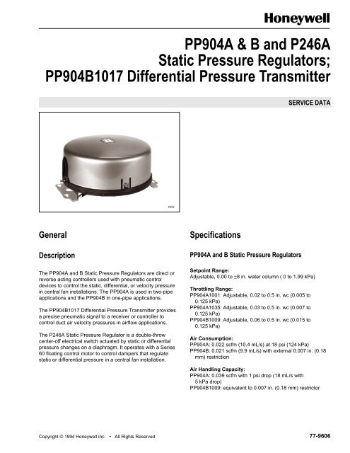
The <strong>PP904A</strong> <strong>and</strong> B <strong>Static</strong> <strong>Pressur</strong>e <strong>Regulators</strong> are direct or<br />
reverse acting controllers used with pneumatic control<br />
devices to control the static, differential, or velocity pressure<br />
in central fan installations. The <strong>PP904A</strong> is used in two-pipe<br />
applications <strong>and</strong> the PP904B in one-pipe applications.<br />
The PP904B1017 Differential <strong>Pressur</strong>e Transmitter provides<br />
a precise pneumatic signal to a receiver or controller to<br />
control duct air velocity pressures in airflow applications.<br />
The <strong>P246A</strong> <strong>Static</strong> <strong>Pressur</strong>e Regulator is a double-throw<br />
center-off electrical switch actuated by static or differential<br />
pressure changes on a diaphragm. It operates with a Series<br />
60 floating control motor to control dampers that regulate<br />
static or differential pressure in a central fan installation.<br />
Copyright © 1994 Honeywell Inc. • All Rights Reserved<br />
RC9<br />
Specifications<br />
<strong>PP904A</strong> <strong>and</strong> B <strong>Static</strong> <strong>Pressur</strong>e <strong>Regulators</strong><br />
SERVICE DATA<br />
Setpoint Range:<br />
Adjustable, 0.00 to ±8 in. water column ( 0 to 1.99 kPa)<br />
Throttling Range:<br />
<strong>PP904A</strong>1001: Adjustable, 0.02 to 0.5 in. wc (0.005 to<br />
0.125 kPa)<br />
<strong>PP904A</strong>1035: Adjustable, 0.03 to 0.5 in. wc (0.007 to<br />
0.125 kPa)<br />
PP904B1009: Adjustable, 0.06 to 0.5 in. wc (0.015 to<br />
0.125 kPa)<br />
Air Consumption:<br />
<strong>PP904A</strong>: 0.022 scfm (10.4 mL/s) at 18 psi (124 kPa)<br />
PP904B: 0.021 scfm (9.9 mL/s) with external 0.007 in. (0.18<br />
mm) restriction<br />
Air H<strong>and</strong>ling Capacity:<br />
<strong>PP904A</strong>: 0.039 scfm with 1 psi drop (18 mL/s with<br />
5 kPa drop)<br />
PP904B1009: equivalent to 0.007 in. (0.18 mm) restrictor<br />
<strong>77</strong>-<strong>9606</strong><br />
<strong>77</strong>-<strong>9606</strong>
<strong>PP904A</strong>,B & <strong>P246A</strong>; PP904B1017<br />
Maximum Safe Air <strong>Pressur</strong>e:<br />
25 psi (175 kPa)<br />
Maximum Safe <strong>Static</strong> <strong>Pressur</strong>e:<br />
28 in. wc (7 kPa)<br />
Ambient Temperature Limits:<br />
40 to 120F (4 to 49C)<br />
PP904B1017 Differential <strong>Pressur</strong>e Transmitter<br />
Zero Adjustment:<br />
0.00 to ±8.0 in. wc (0.00 to 1.99 kPa)<br />
Span Adjustment:<br />
0.06 to 1.0 in. wc (0.015 to 0.25 kPa)<br />
Air Consumption:<br />
0.021 scfm (9.9 mL/s) with external 0.007 in.<br />
(0.18 mm) restriction<br />
Maximum Safe Air <strong>Pressur</strong>e:<br />
25 psi (175 kPa)<br />
Maximum Safe <strong>Static</strong> <strong>Pressur</strong>e:<br />
28 in. wc (7 kPa)<br />
Ambient Temperature Limits:<br />
40 to 120F (4 to 49C)<br />
<strong>77</strong>-<strong>9606</strong><br />
<strong>Static</strong> <strong>Pressur</strong>e Control:<br />
<strong>PP904A</strong> <strong>and</strong> B (Fig. 1)<br />
Direct Acting:<br />
An increase in static pressure causes the PP904 to<br />
increase the branchline pressure.<br />
Reverse Acting:<br />
An increase in static pressure causes the PP904 to<br />
decrease the branchline pressure.<br />
Table 1. Applications.<br />
2<br />
<strong>P246A</strong> <strong>Static</strong> <strong>Pressur</strong>e <strong>Regulators</strong><br />
Control Range:<br />
Positive, negative, or differential pressure. 0.0 to ±6 in. wc<br />
(0 to 1.5 kPa)<br />
Differential:<br />
Adjustable 0.05 to 0.75 in wc (0.012 to 187 kPa). Factory set<br />
at 0.1 in. wc (0.025 kPa)<br />
Maximum Safe <strong>Static</strong> <strong>Pressur</strong>e:<br />
28 in. wc (7 kPa)<br />
Temperature Limits:<br />
40 to 120F (4 to 49C)<br />
Electric Switch rating:<br />
1A at 24V ac<br />
Application<br />
The <strong>PP904A</strong> <strong>and</strong> B Controllers, when used with pneumatic<br />
control devices, control the static <strong>and</strong> differential pressures in<br />
a central fan installation (Table 1). The PP904B1017 is used<br />
as an adjustable-range differential pressure transmitters. The<br />
<strong>P246A</strong> regulator, when used in an electrical control system,<br />
controls the static pressure.<br />
Flow Control:<br />
PP904B1017 <strong>and</strong> <strong>P246A</strong><br />
PP904B1017 (Fig. 2):<br />
This model is used as a transmitter <strong>and</strong> is adjusted to the<br />
exact velocity pressure range required. The output from<br />
the PP904B is the input to a controller, such as the RP920,<br />
which controls the damper.<br />
<strong>P246A</strong> (Fig. 3):<br />
When the static pressure exceeds the static pressure<br />
setting, the <strong>P246A</strong> completes an electrical circuit to a<br />
Series 60 damper motor. The motor positions the dampers<br />
to reduce the static pressure. When the static pressure<br />
reduces to the setpoint of the <strong>P246A</strong>, the electrical circuit<br />
is broken, stopping the motor in this new position. A<br />
second contact drives the motor in the opposite direction<br />
on a decrease in static pressure.
M<br />
20#<br />
FAN<br />
EP<br />
M<br />
20#<br />
FAN<br />
EP<br />
2<br />
4<br />
PRV<br />
305965<br />
RES<br />
FROM<br />
RETURN FAN<br />
4 8 9 7 5<br />
2 3 1 6<br />
6 7<br />
8<br />
1 2 3<br />
3<br />
RP920C<br />
RP670C<br />
RP922A<br />
SUPPLY FAN<br />
B<br />
P M<br />
3<br />
MP920B<br />
WITH POSITIONER<br />
PP904B<br />
RES<br />
A C<br />
S<br />
Fig. 1. <strong>PP904A</strong> or B Typical <strong>Static</strong> <strong>Pressur</strong>e Operation.<br />
RP920C<br />
4 8 9 7 5<br />
2 3 1 6<br />
6 7<br />
8<br />
3<br />
RP670A<br />
SUPPLY FAN<br />
B<br />
P M<br />
MP920B<br />
WITH POSITIONER<br />
2<br />
4<br />
PRV<br />
1 2 3 RP922A<br />
RES<br />
FLOW MEASURE STATION<br />
L H<br />
A C<br />
S<br />
PP904B1017<br />
<strong>PP904A</strong>,B & <strong>P246A</strong>; PP904B1017<br />
STATIC PRESSURE PROBE<br />
Fig. 2. PP904B1017 Typical Operation in Velocity (Flow) Application.<br />
STATIC<br />
PRESSURE<br />
MAGNEHELIC<br />
GAGE<br />
FI<br />
H L<br />
7 6<br />
9 8<br />
H L<br />
7 6<br />
9 8<br />
AIR FLOW<br />
MAGNEHLIC<br />
GAGE<br />
SELECTOR<br />
SWITCH<br />
SELECTOR<br />
SWITCH<br />
C7315<br />
C7313<br />
<strong>77</strong>-<strong>9606</strong>
<strong>PP904A</strong>,B & <strong>P246A</strong>; PP904B1017<br />
TO<br />
POWER<br />
Operation<br />
<strong>77</strong>-<strong>9606</strong><br />
SUPPLY FAN<br />
W<br />
R<br />
B<br />
SERIES 60<br />
MOTOR<br />
AIRFLOW<br />
STATIC<br />
DUCT HEAD<br />
W<br />
R<br />
B<br />
<strong>P246A</strong><br />
Fig. 3. <strong>P246A</strong> Typical Operation.<br />
<strong>Static</strong> <strong>Pressur</strong>e Control: <strong>PP904A</strong>1001 <strong>and</strong><br />
<strong>PP904A</strong>1019<br />
DISCHARGE<br />
AIR<br />
REFERENCE<br />
PRESSURE<br />
C7302<br />
The <strong>PP904A</strong>1001 or <strong>PP904A</strong>1019 (Fig. 4) regulates static<br />
pressure by placing a reference pressure on one side of the<br />
diaphragm <strong>and</strong> static pressure on the other. For direct acting<br />
operation, the reference pressure, reflecting the pressure in<br />
the controlled space, is connected to the lower connector (2);<br />
a duct head assembly located in the duct, which senses the<br />
static pressure, is connected to the top connector (1).For<br />
reverse acting operation the reference pressure is<br />
connected to the top connector <strong>and</strong> the static pressure to the<br />
bottom connector.<br />
When connected direct acting, an increase in the static<br />
pressure disturbs the force balance. The increased force on<br />
the diaphragm (3) exceeds the force of the setpoint springs<br />
(5) (6), <strong>and</strong> pulls down on the main lever (4). Two setpoint<br />
adjustment screws, one for course adjustment (8) <strong>and</strong> the<br />
other (9) for fine adjustment determine the compression on<br />
the setpoint springs. As the main lever moves downward, it<br />
comes into contact with the flapper (10) forcing the flapper<br />
closer to the nozzle (11).<br />
Some of the main air entering the port (12) is diverted<br />
through the restriction (13) to the nozzle <strong>and</strong> the pilot<br />
10<br />
11<br />
13<br />
1<br />
2<br />
BRANCH MAIN<br />
15 19 20 21 22 7 8 9 4<br />
12<br />
16<br />
18 17 14 23 5 6 3<br />
4<br />
pressure chamber (14). The rest of the main air enters the<br />
chamber surrounding the branch check valve (15).<br />
As the flapper is forced closer to the nozzle, air flow through<br />
the nozzle is reduced, increasing the pressure in the pilot<br />
pressure chamber. Increased pressure on the diaphragm (16)<br />
overcomes the check valve spring <strong>and</strong> opens the check<br />
valve (View A) allowing main air to flow into the branch line<br />
(17). <strong>Pressur</strong>e continues to build until the pressure on the<br />
branchline diaphragm balances the pressure on the pilot<br />
pressure chamber diaphragm (14) <strong>and</strong> closes the branchline<br />
check valve. The increased branchline pressure moves the<br />
damper toward the closed position reducing the static<br />
pressure in the duct.<br />
The chamber surrounding the feedback bellows (20) is<br />
maintained at the same pressure as the branch line. As the<br />
branchline pressure increases the bellows pushes up on the<br />
feedback lever (21). The feedback lever operating through<br />
the throttling range adjustment screw (22) lefts up on the<br />
main lever, reducing the pressure on the flapper, bleeding of<br />
the pressure in the pilot pressure chamber <strong>and</strong> reducing the<br />
force on the pilot pressure chamber diaphragm (16) until the<br />
branchline check valve closes to maintain the branchline<br />
pressure at the new pressure.<br />
A decrease in static pressure decreases the force on the top<br />
of the diaphragm (3). The decreased force on the diaphragm<br />
allow the setpoint springs to force the main lever (4) up <strong>and</strong><br />
reduce the force on the flapper. The flapper spring lifts the<br />
flapper off the nozzle, bleeding the pilot pressure chamber<br />
<strong>and</strong> reducing the force on the pilot pressure chamber<br />
diaphragm (16).<br />
Decreased pressure on the pilot pressure chamber<br />
diaphragm allows the branchline diaphragm (18) to open the<br />
branchline check valve guide (view B). Branchline air bleeds<br />
back through the center of the branchline check valve guide<br />
<strong>and</strong> exhaust through the vent (23).<br />
The reduced pressure on the feedback bellows (20) allows<br />
the setpoint springs to pull the main lever down. This<br />
increases the force on the flapper which reduces the amount<br />
of air allowed to escape through the nozzle, increasing the<br />
pressure in the pilot chamber until the branchline check valve<br />
guide reseats against the check valve plug.<br />
Fig. 4. Schematic Cutaway of the <strong>PP904A</strong>1001 <strong>and</strong> <strong>PP904A</strong>1019.<br />
BRANCH EXHAUSTS<br />
MAIN AIR TO BRANCH<br />
C7317
<strong>Static</strong> <strong>Pressur</strong>e Control: <strong>PP904A</strong>1035<br />
The <strong>PP904A</strong>1035 (Fig. 5) regulates static pressure by placing<br />
a reference pressure on one side of the diaphragm <strong>and</strong> static<br />
pressure on the other. For direct acting operation, the<br />
reference pressure, reflecting the pressure in the controlled<br />
space, is connected to the lower connector (A); a duct head<br />
assembly located in the duct, which senses the static<br />
pressure, is connected to the top connector (C). For reverse<br />
acting operation the reference pressure is connected to the<br />
top connector <strong>and</strong> the static pressure to the bottom<br />
connector.<br />
When connected direct acting, an increase in static pressure<br />
causes an increase in the force on the diaphragm. When the<br />
force of the diaphragm exceeds the force of the setpoint<br />
springs, it pulls down on the main lever. Two setpoint<br />
BRANCH<br />
M<br />
FLAPPER<br />
NOZZLE<br />
C<br />
A<br />
Velocity Control: PP904B<br />
C<br />
A<br />
V<br />
4<br />
1<br />
2<br />
BRANCH<br />
RP970A<br />
3<br />
PILOT<br />
Flow control, using the velocity pressure model of the<br />
PP904B (Fig. 6), is accomplished by connecting a velocity<br />
type, two-input probe to both the high <strong>and</strong> low side.<br />
PILOT LINE<br />
MAIN LEVER<br />
THROTTLING RANGE LEVER<br />
THROTTLING RANGE ADJUSTMENT<br />
Fig. 5. Schematic Cutaway of the <strong>PP904A</strong>1035.<br />
Fig. 6. Internal View of PP904B.<br />
5<br />
SET POINT SPRINGS<br />
PP904B<br />
<strong>PP904A</strong>,B & <strong>P246A</strong>; PP904B1017<br />
adjustment screws, one for course adjustment <strong>and</strong> the other<br />
for fine adjustment determine the compression on the<br />
setpoint springs. As the main lever moves downward, it<br />
comes into contact with the flapper forcing the flapper closer<br />
to the nozzle. Less air is allowed to bleed off which increases<br />
the pressure in the pilot line <strong>and</strong> in the feedback chamber.<br />
Increased pressure in the feedback chamber compresses the<br />
feedback bellows increasing the force on the throttling range<br />
lever. The force on the throttling range lever lifts the main<br />
lever away from the nozzle until all forces are back in balance.<br />
The RP970A Relay isolates the pilot line from the branch line,<br />
repeats the same pressure as the pilot line, <strong>and</strong> increases the<br />
capacity of the signal to the damper actuator. Refer to<br />
Pneumatic Relays <strong>and</strong> Switches <strong>77</strong>-9384 for operation of the<br />
RP970A Relay.<br />
FEEDBACK BELLOWS<br />
FEEDBACK CHAMBER<br />
C7322<br />
An increase in velocity above the setting made on the<br />
regulator causes the main lever to close off the nozzle,<br />
increasing the branchline pressure to the damper operator.<br />
C7323<br />
<strong>77</strong>-<strong>9606</strong>
<strong>PP904A</strong>,B & <strong>P246A</strong>; PP904B1017<br />
Maintenance<br />
Equipment Required<br />
Test Panel as described in Pneumatic Airflow Control<br />
Systems Checkout <strong>and</strong> Test <strong>77</strong>-5031<br />
CCT854: 50 cc <strong>Pressur</strong>e Syringe<br />
CCT863: 10 cc <strong>Pressur</strong>e Syringe<br />
CCT853A: Flexible Tubing to connect<br />
Cleaning<br />
Use a common household spray degreasing agent (such as<br />
Fantastic) to remove dirt <strong>and</strong> grease from regulator.<br />
Operation Check<br />
Adjust the regulator setpoint <strong>and</strong> observe the operation of the<br />
damper operator. With the system in operation <strong>and</strong> the<br />
regulator in control, connect a static pressure gage with<br />
sufficient range for the application, across the two connectors<br />
(Fig. 7). If the gage reading is correct, relative to the setpoint,<br />
the system is operating properly.<br />
<strong>77</strong>-<strong>9606</strong><br />
STATIC PRESSURE GAGE<br />
STATIC CONNECTOR<br />
REFERENCE PORT<br />
AIR<br />
FLOW<br />
C7303<br />
Fig. 7. Installing a <strong>Static</strong> <strong>Pressur</strong>e Gage on the <strong>PP904A</strong><br />
<strong>and</strong> B or <strong>P246A</strong>.<br />
If you are unable to get the correct reading <strong>and</strong> all other<br />
related criteria are met (e.g., correct supply air <strong>and</strong> damper<br />
operation), check the calibration as follows:<br />
Calibration<br />
<strong>PP904A</strong> <strong>and</strong> B <strong>Static</strong> <strong>Pressur</strong>e or Differential<br />
Control (Fig. 7)<br />
Set the throttling range to the desired setting.<br />
Set the setpoint indicator to the desired setting.<br />
Connect the static pressure gage across the input<br />
ports (Fig. 7).<br />
6<br />
With the system in operation, check the static<br />
pressure gage for the desired pressure.<br />
If the gage reading differs from the actual setpoint,<br />
adjust the large knurled screw (course adjustment,<br />
Item 35, Parts List) until the correct reading<br />
is reached.<br />
On very low throttling ranges, it may be necessary to<br />
use the small knurled screw (Item 34, Parts List) for<br />
fine settings.<br />
After making any changes in the setting, allow<br />
sufficient time for the system to stabilize <strong>and</strong> recheck<br />
the calibration.<br />
NOTES:<br />
1. The branchline pressure changes with every<br />
adjustment made.<br />
2. Repeat the calibration procedures anytime the<br />
throttling range setting is changed.<br />
PP904B Velocity Transmitter Applications<br />
Determine the “Min-Max” velocities to be encountered<br />
<strong>and</strong> the equivalent velocity pressures. Zero adjust the<br />
Min value for 3 psi (21 kPa) using the setpoint<br />
adjustment <strong>and</strong> span adjust the Max value to 15 psi<br />
(103 kPa) using the throttling range adjustment.<br />
Install a gage across the inputs. Use a syringe to<br />
apply <strong>and</strong> remove a signal on the high side pick-up<br />
with the low side open.<br />
<strong>P246A</strong><br />
Adjust the coarse adjustment screw to position the<br />
pointer at the desired setpoint.<br />
Connect the static pressure gage across the two<br />
static pressure head connectors (Fig. 7).<br />
With the system in full operation, check the gage for a<br />
differential pressure reading. If the gage reading is<br />
correct, <strong>and</strong> the switching lever is between the<br />
contacts, the calibration is correct.<br />
If the gage reading is different than the setpoint<br />
setting, check the calibration by manually<br />
positioning the motor until the regulator <strong>and</strong> gage<br />
setpoints agree.<br />
Disconnect the motor leads <strong>and</strong> position the main<br />
lever, using the large knurled screws, to achieve a<br />
floating action of the switching lever.<br />
The regulator is correctly calibrated. Reconnect<br />
motor leads.<br />
If it is necessary to decrease the differential, adjust<br />
the contact point screw clockwise equally on the blue<br />
<strong>and</strong> white terminals. To increase the differential, back<br />
off the contact screws (counterclockwise).
Troubleshooting<br />
A 1-in. draft gage, squeeze bulb is required for troubleshooting (Fig. 9).<br />
DISCONNECT<br />
STATIC INPUT LINES.<br />
INSTALL 0 TO 10 IN. WC<br />
MANOMETER AND SYRINGE<br />
ON HIGH STATIC PORT.<br />
USE SYRINGE TO<br />
SIMULATE VARIOUS<br />
STATICS THE CONTROLLER<br />
IS SET UP FOR.<br />
DO<br />
BUILD-UP AND<br />
BLEED-DOWN OR SWITCH<br />
ACTIONS FUNCTION<br />
PROPERLY<br />
?<br />
YES<br />
UNIT IS OPERATING<br />
PROPERLY.<br />
NO<br />
RECALIBRATE.<br />
REPLACE THE SWITCHING<br />
UNIT IN THE P246 AND<br />
RECALIBRATE.<br />
DID<br />
THE UNIT<br />
RECALIBRATE<br />
PROPERLY<br />
?<br />
YES<br />
NO<br />
DID<br />
THE UNIT<br />
RECALIBRATE<br />
PROPERLY<br />
?<br />
Fig. 8. Troubleshooting Chart.<br />
7<br />
YES<br />
REPLACE THE <strong>P246A</strong>.<br />
NO<br />
<strong>P246A</strong><br />
<strong>PP904A</strong>,B & <strong>P246A</strong>; PP904B1017<br />
IS THE<br />
UNIT A <strong>P246A</strong> OR<br />
A PP904<br />
?<br />
PP904<br />
REPLACE THE<br />
RESTRICTION NOZZLE<br />
ASSEMBLY ON THE VALVE<br />
ASSEMBLY AND SEAT THE<br />
NOZZLE AGAINST THE FLAP<br />
BY ADJUSTING THE<br />
SETPOINT (SEE THE )t<br />
(REPAIR SECTION) AND<br />
THEN RECALIBRATE.<br />
DID<br />
THE UNIT<br />
RECALIBRATE<br />
PROPERLY<br />
?<br />
YES<br />
NO<br />
REPLACE THE PP904.<br />
C7304<br />
<strong>77</strong>-<strong>9606</strong>
<strong>PP904A</strong>,B & <strong>P246A</strong>; PP904B1017<br />
Repair<br />
<strong>77</strong>-<strong>9606</strong><br />
A<br />
C B<br />
PP904 OR PP905<br />
PRESSURE SYRINGE<br />
VENT<br />
0 TO 10 IN. WC MANOMETER<br />
For assembly <strong>and</strong> disassembly, refer to exploded view<br />
diagram in parts section.<br />
Seating Nozzle in PP904<br />
Adjust the setpoint until the flapper is firmly against<br />
the nozzle (Item 22, Fig. 10).<br />
Raise the flapper 1/2 in. <strong>and</strong> allow it to snap back.<br />
RESTRICTION<br />
(PROVIDED WITH PP905B)<br />
Fig. 9. <strong>Pressur</strong>e Syringe Connection Diagram.<br />
8<br />
3-15 PSI GAGE, MINOR SCALE DIV. 0.1 PSI<br />
(14506496-201 & 14505846-122)<br />
20 PSI<br />
M<br />
0.007 RESTRICTOR<br />
TO PROTECT GAGE<br />
Replacing PP904 Restriction Nozzle<br />
Assembly<br />
C7305<br />
Use Repair Kit Number 14002697-001 for all <strong>PP904A</strong>s <strong>and</strong><br />
PP904Bs.<br />
NOTE: The instructions listed on the kit apply to round<br />
thermostats. The nozzle assembly replacement on<br />
the PP904 is similar. Discard the filters furnished in<br />
the kit.
Parts List <strong>and</strong> Accessories<br />
Table 2. Parts List <strong>and</strong> Accessories.<br />
9<br />
<strong>PP904A</strong>,B & <strong>P246A</strong>; PP904B1017<br />
Key Description (Part Number) Key Description (Part Number)<br />
1.* Screw—No. 8-32 x 3/8 in. Pan Head Recessed 43. Nut—No. 8-32 x 1/8 in. Hex<br />
2. Not Used 44. Screw—No. 6-32 x 1/2 Pan Head Recessed<br />
3. Bracket—Mounting Left H<strong>and</strong> Form 45. Cap—Holding Ring (314840)<br />
4. Bracket—Mounting Right H<strong>and</strong> Form 46. Knob—Knurled Type, <strong>PP904A</strong> & B Only (314844)<br />
5. Plate Assembly (all models) 47. Adjustment Indicator—<strong>PP904A</strong> & B Only<br />
6. Screw—No. 8-32 x 1/2 in. Pan Head Recessed 48. Nut—TR Slide Adjustment, <strong>PP904A</strong> & B Only<br />
Screw—No. 8-32 x 1-1/4 in. for B1017 49. Nut—No. 2-56 Hex<br />
7. Barb Connector 1/4-in. ( 6-mm) O.D. (CCT1607B) 50. Pivot Assembly—Ball-point Head Type (314927A)<br />
8. Diaphragm (314670) 51. Spring (314841)<br />
9. Screw—No. 6-32 x 1/4 in. Pan Head Recessed 52.* Lever—Electrical Contact<br />
10. Disc—Diaphragm Holder 53.* Washer—No. 2-56 Flat Brass<br />
11. Seal 54.* Insulator—Contact Blade<br />
12. "O" Ring—Seal Type (311472) 55.* Contact Blade Assembly (14001232-001)<br />
13. Spacer—Ring Type Adapter 56.* Screw—No. 2-56 x 1/4 in. Round Head Slotted<br />
14. Diaphragm—Molded Neoprene (314848) 57.* Leadwire Assembly—Common Connector<br />
15. Post 58.* Contact Screw Assembly (24632A)<br />
16. Spring—Setpoint (314852) 59.* Post—Terminal Contact<br />
17. Screw—Cover, No. 10-32 x 3/8 in. Acorn Washer Head 60.* Washer—3/8 Brass Spacer<br />
18. Base 61.* Insulator<br />
19. Scale 62.* Washer—Blue Marker for Terminal Post<br />
20. Screw—No. 8-32 x 1/4 in. Pan Head Recessed 63.* Lockwasher—No. 1108 Shakeproof<br />
21.* Nut—No. 4-40 Hex 64.* Nut—No. 8-32 Hex, Brass Terminal Post<br />
22. Lever—Flapper, <strong>PP904A</strong> & B Only (314855) 65.* Terminal—Wire Connection (314853)<br />
23.* Screw—No. 4-40 x 1/4 in. Pan Head Recessed 66.* Nut—Terminal Knurled<br />
24. Plate (314843) 67.* Washer—White Marker for Terminal Post<br />
25. Spring (314842) 68.* Washer—Red Marker for Terminal Post<br />
26. Bracket 69.* Screw—No. 8-32 x 3/4 in. Round Head Slotted,<br />
Common Connector<br />
27. Spring (303634) 70.* Bracket<br />
28. Spring—Compression, Coarse Adjustment 71.* Bracket—Insulator Holder<br />
29. Stud—No. 8-32 — Cover (Not Shown)<br />
30. Nut—No. 8-32 x 1/4 in. Hex 72. Tubing, Plastic 5/32-in. (3-mm) O.D.<br />
31. Lever—Scale Indicating 73. Restrictor, Tee (315559F<br />
32. Set Screw—No. 4-40 x 3/16 in. Socket 74. Tubing, Plastic 5/32-in. (3-mm) O.D.<br />
33. Locknut—Inverted Tension (304721) 75. Tubing, Plastic 5/32-in. (3-mm) O.D.<br />
34. Knob—Knurl, Fine Adjustment (314860) 76. Capacity Relay (RP970A1008)<br />
35. Knob—Knurl, Coarse Adjustment (314859) <strong>77</strong>. Elbow 1/4- in. (6 mm) O.D. 90˚ (CCT 1638)<br />
36. Lever—Fine <strong>and</strong> Coarse Adjustment 78. Brass Tee 1/4- in. (6 mm) O.D. (CCT1630B)<br />
37. Pointer—Scale 79. Tubing, Plastic 1/4-in. (6-mm) O.D.<br />
38. Pin—Lever Base Connector 80. Tubing, Plastic 5/32-in. (3-mm) O.D.<br />
39. Nut—Pushnut, Self-locking 81. Barb Connector 5/32-in. (3-mm) O.D. (CCT1628B)<br />
40. Lever—Main 82. Relay Clip (14003030-001)<br />
41. Screw—No. 8-32 x 3/4 in. Pan Head Recessed 83. Washer<br />
42.* Nut—No. 8-32 Self-locking (except B1017) 84. Tubing, Plastic 1/4-in. (6-mm) O.D.<br />
* Available as assembled unit (314869) refer to Figure 13.<br />
NOTES:<br />
1. See Figures 12, 13, <strong>and</strong> 14 for 314755B (<strong>PP904A</strong>)<br />
<strong>and</strong> 14003348-001 (PP904B) Pneumatic Valve Units.<br />
2. Obtain st<strong>and</strong>ard hardware parts locally.<br />
3. Parts 51 through 71 are for <strong>P246A</strong> only (Fig. 11).<br />
4. Parts 72 through 82 are for <strong>PP904A</strong>1035 only.<br />
<strong>77</strong>-<strong>9606</strong>
<strong>PP904A</strong>,B & <strong>P246A</strong>; PP904B1017<br />
<strong>77</strong>-<strong>9606</strong><br />
Fig. 10. <strong>PP904A</strong>, PP904B, <strong>and</strong> <strong>P246A</strong> Exploded View.<br />
10
M<br />
RESTRICTION REPAIR KIT<br />
(14002697-001) C7310<br />
Fig. 12. <strong>PP904A</strong>1001 Valve Assembly (314755B).<br />
Fig. 11. <strong>P246A</strong> Electrical Switch Assembly.<br />
11<br />
<strong>PP904A</strong>,B & <strong>P246A</strong>; PP904B1017<br />
RESTRICTION REPAIR KIT<br />
(14002697-001) C7309<br />
Fig. 13. <strong>PP904A</strong>1035 Valve Assembly (14003348-002).<br />
<strong>77</strong>-<strong>9606</strong>
<strong>PP904A</strong>,B & <strong>P246A</strong>; PP904B1017<br />
Home <strong>and</strong> Building Control<br />
Honeywell Inc.<br />
Honeywell Plaza<br />
P.O. Box 524<br />
Minneapolis, MN 55408-0524<br />
<strong>77</strong>-<strong>9606</strong> 2-94<br />
14002913-002<br />
FILTER RESTRICTION<br />
RESTRICTION REPAIR KIT<br />
(14002697-001) C7308<br />
Fig. 14. PP904B Valve Assembly (14003348-001).<br />
Home <strong>and</strong> Building Control<br />
Honeywell Limited-Honeywell Limitée<br />
740 Ellesmere Road<br />
Scarborough, Ontario<br />
M1P 2V9<br />
12<br />
Printed in U.S.A.<br />
on Recycled Paper<br />
Helping You Control Your World