COMPOSITE pt3 - Aux Heater V220.pdf - BenzWorld.org
COMPOSITE pt3 - Aux Heater V220.pdf - BenzWorld.org
COMPOSITE pt3 - Aux Heater V220.pdf - BenzWorld.org

Create successful ePaper yourself
Turn your PDF publications into a flip-book with our unique Google optimized e-Paper software.
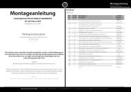
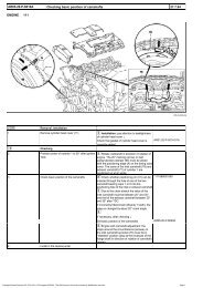
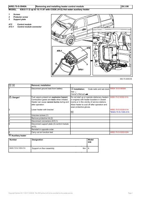
AR83.70-S-5940A Removing and installing heater control module 29.3.96<br />
MODEL 638.0 /1 /2 up to 15.11.97 with CODE (H12) Hot water auxiliary heater<br />
1 Screws<br />
2 Protector screw<br />
3 Support plate<br />
A72 Control module<br />
A72.1 Control module connector<br />
e d<br />
Removal, installation<br />
1 Disconnect ground lead from battery i AR54.10-S-0005A<br />
Installation: Code radio and set clock<br />
See @<br />
Owner's Manual l<br />
S83.70-2009-06<br />
a Danger!<br />
Fuel vapors present an explosion hazard. Do not start up or operate stationary heaters AS83.70-Z-0002-01A<br />
Combustion gases are toxic when inhaled. or engines with heater boosters in closed<br />
<strong>Heater</strong> can cause severe burns during and rooms or in the vicinity of service stations.<br />
after operation Allow heater to cool off after operation and<br />
wear protective gloves.<br />
2 Lower heater with bracket AR83.70-S-5330-01A<br />
n<br />
*BA83.70-N-1005-01A<br />
3 Unscrew screws (1)<br />
4 Remove protective lid (2)<br />
5 Disconnect connectors (A72.1)<br />
6 Disconnect support plate (3) control module<br />
(A72)<br />
7 Reinstall in opposite order<br />
8 Carry out an function test AR83.70-S-5302-02A<br />
n <strong>Aux</strong>iliary heater<br />
Number Designation Model<br />
638<br />
BA83.70-N-1005-01A Support on floor assembly Nm 8<br />
Copyright Daimler AG 11/25/11 G/06/08. This WIS printout will not be recorded by the update service. Page 1
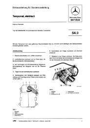
AR83.70-S-5980A Removing and installing the heater temperature controlled cut-out 28.3.96<br />
MODEL 638.0 /1 /2 up to 15.11.97 with CODE (H12) Warm water auxiliary heater<br />
D5W or B5W<br />
1 Coolant hoses<br />
2 Connector box<br />
3 lClamp<br />
B95 Temperature controlled cut-out<br />
B95.1 Two-pin plug-in connection<br />
e d<br />
Removal, installation<br />
1 Disconnect the ground cable from the battery i AR54.10-S-0005A<br />
Installation: Code the radio<br />
Set the clock<br />
a Danger!<br />
a Danger!<br />
Refer to @<br />
Owner's Manual l<br />
S83.70-2005-06<br />
Risk of explosion due to fuel vapors Do not put stationary heater or engine with AS83.70-Z-0002-01A<br />
igniting, risk of poisoning due to heater booster into operation in confined<br />
combustion gases and risk of injury from spaces or while refuelling. Allow heater unit<br />
burns during and after heater operation. to cool down after operation and wear safety<br />
gloves.<br />
Danger of severe burns to skin and eyes Open cooling system only when coolant AS20.00-Z-0001-01A<br />
from hot coolant spewing out. Coolant is temperature is below 90 °C. Open cover<br />
toxic when swallowed slowly and reduce pressure. Do not fill<br />
beverage containers with coolant. Wear<br />
protective gloves, protective clothing and<br />
protective goggles.<br />
2 Eliminate the pressure from the coolant<br />
circuit<br />
3 Lower the heater with support AR83.70-S-5330-01A<br />
n<br />
*BA83.70-N-1005-01A<br />
4 Disconnect the coolant hoses (1) with clamp l *000589543700<br />
(3)<br />
5 Remove the connector box lid (2) i AR83.70-S-5940-01A<br />
Installation: Make sure the joints are<br />
correctly seated<br />
6 Disconnect the plug-in connection (B95.1)<br />
7 Unscrew the temperature controlled cut-out i Collect any coolant<br />
(B95) in a suitable container<br />
8 Reinstall in opposite order<br />
i Installation: grease the joint of the<br />
temperature controlled cut-out<br />
n<br />
*BR00.45-Z-1015-06A<br />
*BA83.70-N-1002-01A<br />
a Danger!<br />
Accident hazard resulting from vehicle Secure vehicle against starting to move<br />
starting to move by itself with engine running. unintentionally.<br />
Danger of injury resulting from pinching and Wear closed and tight fitting work clothing.<br />
AS00.00-Z-0005-01A<br />
burning when reaching in during the starting<br />
operation or with the engine running.<br />
Do not touch hot or rotating parts.<br />
Copyright Daimler AG 11/25/11 G/06/08. This WIS printout will not be recorded by the update service. Page 1
9 Start up the engine; purge the air from the Heat the engine with variable revolutions for<br />
cooling and heating system. approximately 1 minute.<br />
Continuously fill with coolant until it reaches<br />
the upper mark on the coolant filler neck.<br />
a Gefahr!<br />
Risk of explosion due to fuel vapors Do not put stationary heater, auxiliary heater AS83.70-Z-0002-01A<br />
igniting, risk of poisoning due to inhaling or engine with heater booster into operation<br />
combustion gases and risk of injury from in confined spaces or while refuelling. Allow<br />
burns during and after heater operation. heater unit to cool down after operation and<br />
wear safety gloves.<br />
10 Stop the engine<br />
11 Carry out an operation test AR83.70-S-5302-02A<br />
n Independent heater<br />
Number Designation Model<br />
638<br />
BA83.70-N-1002-01A Temperature controlled cut-out in heat exchanger Nm 3<br />
box<br />
BA83.70-N-1005-01A Support on floor set Nm 8<br />
000 589 54 37 00<br />
Clamp<br />
Repair materials<br />
Number Designation Order number<br />
BR00.45-Z-1015-06A Vaseline -<br />
Copyright Daimler AG 11/25/11 G/06/08. This WIS printout will not be recorded by the update service. Page 2
AR83.70-S-5335A Removing heater from support 29.3.96<br />
MODEL 638.0 /1 /2 up to 15.11.97 with CODE (H12) Hot water auxiliary heater<br />
1 Air intake muffler for combustion<br />
2 Exhaust gas system<br />
3 Clamp<br />
4 Support<br />
A34 Hot water auxiliary heater<br />
A72 Control module<br />
e d<br />
Removal, installation<br />
1 Remove heater with support AR83.70-S-5330A<br />
2 Remove exhaust gas system (2) from AR83.70-S-7000A<br />
support (4)<br />
3 Remove control module (A72) from support AR83.70-S-5940A<br />
(4)<br />
4 Remove cable clamp, remove clamp (3),<br />
remove hot water auxiliary heater (A34) from<br />
support<br />
i Installation: replace the cable clamp<br />
5 Reinstall in opposite order<br />
S83.70-2013-03<br />
Copyright Daimler AG 11/25/11 G/06/08. This WIS printout will not be recorded by the update service. Page 1
AF83.70-S-6400A Stationary, auxiliary heater does not operate occasionally 20.5.98<br />
MODEL 638.### ## as of 41715 up to 95807 with CODE (H12) Hot water auxiliary heater<br />
Revisions<br />
26.2.99 Supersedes STIV no. 83.70-015 dated 18.2.99 and<br />
STIN no. 83.70V001 dated 15.2.99<br />
Damage code Cause Remedy<br />
83 513 90 Control module defective 1 Replace control module. AR83.70-S-5940A<br />
Parts ordering notes<br />
p Affected control modules can be ordered<br />
i Overheat protection trips from GLC Germersheim specifying Index 05<br />
i Return defective control modules to GLC<br />
Germersheim specifying part number (with<br />
Index 06).<br />
Part no. Designation Quantity<br />
000 446 34 29 05 Control module B5W 638 835 09 01 with "Heatmatic" as required<br />
000 446 35 29 05 Control module D5W 638 835 08 01 without "Heatmatic" as required<br />
000 446 36 29 05 Control module D5W 638 835 10 01 with "Heatmatic" as required<br />
000 446 46 29 05 Control module B5W 638 835 07 01 without "Heatmatic" as required<br />
Copyright Daimler AG 11/25/11 G/06/08. This WIS printout will not be recorded by the update service. Page 1
AD83.70-S-3004A <strong>Heater</strong> booster (HB) diagnosis operational check 18.8.98<br />
MODEL 638 with ENGINE 611.980<br />
with CODE (MQ3) Engine OM611 DE22 A (60 kW)<br />
with CODE (MQ4) Engine OM611 DE22 LA (75 kW)<br />
with CODE (MQ5) Engine OM611 DE22 LA (90 kW)<br />
MODEL 638 with ENGINE 611.980 with CODE (HZ5) Hot water auxiliary heater 10 kW with timer<br />
a Danger!<br />
Risk of explosion due to fuel vapors, risk of Do not put stationary heater or engine with AS83.70-Z-0002-01A<br />
poisoning from combustion gases and risk heater booster into operation in confined<br />
of injury from burning during or after heater spaces or in the vicinity of tank installations.<br />
operation Allow heater unit to cool down after operation<br />
and wear protective gloves.<br />
<strong>Heater</strong> booster (ZUH) diagnosis, previous AD83.70-S-2002A<br />
knowledge<br />
ZUH function notes AD83.70-S-2002-04A<br />
Function control<br />
Scope of test Operation/requirement Specified value Possible cause /<br />
remedy<br />
1<br />
Switching heater<br />
Engine: RUNNING AD83.70-S-6002-02A<br />
booster on and off via<br />
climate control<br />
Sufficient fuel in tank<br />
pushbutton control unit Press heater booster switch (A20s6) on Display illuminated in climate control<br />
climate control pushbutton control unit pushbutton control unit and heater booster<br />
switches on<br />
Press heater booster switch (A20s6) on Display goes out and heater booster turns<br />
climate control pushbutton control unit again itself off<br />
Run-on time of the air blower: 120sec.<br />
Not available if no fuel has been drawn<br />
Copyright Daimler AG 11/25/11 G/06/08. This WIS printout will not be recorded by the update service. Page 1
PE83.70-S-2001D Wiring diagram of auxiliary heater (AHE) 27.10.97<br />
MODEL 638.014 /034 /064 /074 /114 /134 /164 /174 /214 /234 /244 /274 as of 23.4.98 with CODE (H12) Warm water auxiliary<br />
heater<br />
PE83.70-S-2001-99D Wiring diagram auxiliary heater (AHE) PE83.70-S-2001-99D<br />
PE83.70-S-2001-60D Legend of wiring diagram auxiliary heater PE83.70-S-2001-60D<br />
(AHE)<br />
OV00.01-N-1901-03A Use of wiring diagrams OV00.01-N-1901-03A<br />
OV00.01-N-1901A Search aid through all wiring diagram groups OV00.01-N-1901A<br />
OV00.01-N-1001-27A Abbreviations for wiring diagrams OV00.01-N-1001-27A<br />
GF00.19-S-1100A Arrangement and assignment of plug GF00.19-S-1100A<br />
connections and sockets<br />
GF00.19-S-2000A Arrangement and assignment of ground GF00.19-S-2000A<br />
points<br />
GF00.19-S-3100A Arrangement and assignment of terminal GF00.19-S-3100A<br />
blocks<br />
PE00.19-S-1100A Survey of wiring diagrams covering all Connecting wiring diagrams PE00.19-S-1100A<br />
function groups<br />
GF54.15-S-1255FA Assignment and cable connections of fuse GF54.15-S-1255FA<br />
i see microfilm group 54<br />
blocks Valid for model designation 638.244<br />
GF54.15-S-1255GA Assignment and cable connections of fuse i GF54.15-S-1255GA<br />
see microfilm group 54<br />
blocks Valid for all model designations except<br />
638.094/194/244/294 as of 23.4.98<br />
S83.70-0042-09<br />
Copyright Daimler AG 11/25/11 G/06/08. This WIS printout will not be recorded by the update service. Page 1