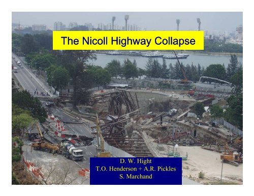
The Nicoll Highway Collapse
The Nicoll Highway Collapse
The Nicoll Highway Collapse

Create successful ePaper yourself
Turn your PDF publications into a flip-book with our unique Google optimized e-Paper software.
<strong>The</strong> <strong>Nicoll</strong> <strong>Highway</strong> <strong>Collapse</strong><br />
D W Hi ht<br />
D. W. Hight<br />
T.O. Henderson + A.R. Pickles<br />
S. Marchand
Content<br />
• Background and construction sequence<br />
• Observations up to the point of collapse, including<br />
monitoring<br />
• <strong>The</strong> collapse<br />
• Post-collapse investigations<br />
• Design errors<br />
• Jet grout layers<br />
• Ground conditions and the buried valley<br />
• <strong>The</strong> need for a trigger<br />
• Back analyses of the collapse<br />
• Relative vertical displacement and forced sway<br />
• <strong>The</strong> bored piles<br />
• <strong>Collapse</strong> mechanism and its trigger<br />
• Lessons to be learnt
C825<br />
34m Diameter<br />
Temporary Staging<br />
Area (TSA) Shaft -<br />
35m deep<br />
210m 2-cell cut &<br />
cover tunnels<br />
200m cut 30m & cover - 33m deep<br />
stacked 4-cell<br />
scissors crossover<br />
3-level cut & cover tunnel<br />
Station (NCH) 25m - 30m deep<br />
370m stacked 2-cell<br />
cut & cover tunnel<br />
20m - 25m deep<br />
C824 - 2km of cut and cover construction<br />
mostly in soft clay - up to 35m deep<br />
C824<br />
<strong>Collapse</strong> site<br />
M3 area<br />
Circle Ci Circle l Li Line St Stage 1<br />
800m twin bored<br />
tunnel<br />
3-level cut & cover<br />
Station (BLV)<br />
35m 2-cell cut and<br />
cover tunnel<br />
550m 2-cell cut &<br />
cover tunnel and<br />
siding (BLS)
Plaza Hotel<br />
<strong>The</strong> Concourse<br />
NCH station<br />
Courtesy of Richard Davies<br />
Reclamation dates<br />
Golden Mile<br />
Tower<br />
Cut and Cover<br />
tunnels<br />
Beach Road<br />
1930-1940’s<br />
1930-1940 s<br />
reclamation<br />
GGolden ld Mil Mile<br />
Complex<br />
1970’s<br />
reclamation<br />
<strong>Nicoll</strong> <strong>Highway</strong><br />
TSA<br />
shaft<br />
MMerdeka d k<br />
Bridge<br />
Kallang<br />
Basin
NORRTHING<br />
(m)<br />
ABH27<br />
31700<br />
31650<br />
31600<br />
MC2025<br />
54+812<br />
ABH81<br />
ABH28<br />
M2<br />
MC3007<br />
ABH82<br />
ABH83<br />
ABH29<br />
54+900<br />
ABH30<br />
M3010<br />
ABH32<br />
M3<br />
ABH84<br />
AC-3<br />
ABH31<br />
MC2026<br />
ABH85<br />
AC-2<br />
ABH34<br />
AC-4<br />
AC-1<br />
MC3008<br />
31550 31600 31650 31700 31750 31800<br />
EASTING (m)<br />
ABH33<br />
M2064 M2065<br />
Pre- and post-tender site investigation<br />
ABH35
100<br />
90<br />
80<br />
70<br />
SOUTH NORTH<br />
ABH 31 ABH 32<br />
Fill<br />
Upper estuarine<br />
UUpper<br />
Marine<br />
Clay<br />
Upper F2<br />
M309<br />
M304<br />
Fill<br />
Upper estuarine<br />
Upper<br />
Marine<br />
Clay<br />
Upper F2<br />
Lower<br />
Lower<br />
Marine<br />
Marine<br />
Clay Clay<br />
Base marine clay<br />
Old<br />
Alluvium<br />
Top of OA<br />
Typical section in M3<br />
Lower o e<br />
estuarine<br />
Lower F2<br />
Old<br />
Alluvium
Depth (m)<br />
Cone resistance, qc (MPa)<br />
0 04 0.4 08 0.8 12 1.2 16 1.6 2<br />
0<br />
10<br />
20<br />
AC1<br />
AC2<br />
AC3<br />
AC4<br />
30 30<br />
40 40<br />
Depth (m)<br />
Piezocone data for M3 area<br />
Undrained shear strength (kPa)<br />
0<br />
0<br />
20 40 60 80 100<br />
10<br />
20<br />
AC1<br />
AC2<br />
AC3<br />
AC4<br />
Nkt=12
Construction details and sequence
Formation level<br />
approx 33m bgl<br />
Temporary diaphragm<br />
walls,0.8m<br />
Driven kingpost gp<br />
SOUTH NORTH<br />
Permanent bored piles<br />
supporting<br />
rail boxes Sacrificial JGP<br />
10 levels of steel struts at<br />
3m +3.5m vertical<br />
centres<br />
Permanent JGP<br />
Fill<br />
Upper E<br />
Upper<br />
Marine Clay<br />
Upper F2<br />
Lower<br />
Marine Clay<br />
Lower E<br />
Lower F2<br />
OA SW2 (N=35)<br />
OA SW1 (N (N=72) 72)<br />
OA (CZ)
General Excavation sequence for M3 – up to level for<br />
removal of sacrificial JGP and installation of 10 th level strut
M3<br />
M2<br />
TSA Shaft<br />
Utility crossings<br />
<strong>Nicoll</strong><br />
<strong>Highway</strong><br />
Curved walls<br />
Tidal sea<br />
24/3/04
No waler<br />
C channel stiffener<br />
Walers<br />
M3<br />
Shaft<br />
Jacking point<br />
Non-splayed strut<br />
Splayed strut<br />
Kingpost<br />
Support beam<br />
M2
Two Struts Bearing<br />
Direct on Single panel<br />
Single g Strut with Splays y<br />
Bearing on Waler for Single<br />
panel<br />
Struts on Walers - No Splays<br />
Gaps in Diaphragm Wall for 66kV Crossing
South side 13 March 04
Events Events and and observations observations prior to collapse
Plate stiffener<br />
C channel<br />
stiffener<br />
Replacement of plate stiffeners at strut strut-waler waler connection
C channel<br />
connection<br />
Strut bearing<br />
directly on Dwall
Excavation for the 10th Excavation for the 10 level of struts, including removal of the sacrificial JGP
Observations on the morning of the collapse
M301<br />
333<br />
334<br />
M302<br />
M303<br />
North wall<br />
M304<br />
M305<br />
4 2 3<br />
1<br />
6 7<br />
335 336 337 338 339 340<br />
H H H<br />
KP 181 KP 182<br />
KP 183<br />
1 5 5 5 7 7<br />
M306 M307 M308 M309 M310<br />
1 Order in which distortion to waler noted<br />
Excavation to 10 th complete<br />
Excavation in progress<br />
Location of walers, splays and Dwall gaps
S335 S335-99<br />
Strut 335-9 south wall
Strut 338 338-9 9 north wall<br />
S338 S338-99
Instrumentation and results of monitoring
M2<br />
GWV24<br />
I 65<br />
M2/M3 plan at 9 th level<br />
I 104<br />
M3<br />
All struts at S335<br />
instrumented for load<br />
measurements<br />
TSA Shaft
SG3358 Total Force<br />
SG3359 Total Force<br />
Excavation Front for<br />
10th Level Advancing<br />
from S338<br />
140<br />
15th April<br />
130<br />
120<br />
Excavation Front<br />
Approaches S335 at<br />
the end of Day y Shift on<br />
17th April 2004<br />
Excavation Front<br />
Beyond S335 at the<br />
start of Day Shift on<br />
18th April 2004<br />
5000<br />
4500<br />
4000<br />
3500<br />
3000<br />
2500<br />
2000<br />
strut loadd<br />
(kN)<br />
1500<br />
10th Level Between 1000easured<br />
Excavation Front for<br />
110<br />
S336 and S335 M<br />
16th April<br />
100<br />
90<br />
17th April<br />
80<br />
70<br />
60<br />
18th April<br />
Hours before collapse<br />
50<br />
40<br />
19th April<br />
30<br />
20<br />
10<br />
500<br />
20th April<br />
0<br />
0
(kN)<br />
Meeasured<br />
strut<br />
load<br />
5000<br />
4500<br />
4000<br />
3500<br />
3000<br />
2500<br />
2000<br />
1500<br />
1000<br />
500<br />
Change in Measured Load at Strut 335<br />
336(N) & 337(N)<br />
Waler Buckling Observed 335(N)<br />
Support Bracket Waler at 335(S) Buckling Drops Observed Off<br />
Strut Load 335-9<br />
Strut Load 335-8<br />
338(N) & 335(S)<br />
Waler Buckling Observed<br />
0<br />
6.00 7.00 8.00 9.00 10.00 11.00 12.00 13.00 14.00 15.00 16.00<br />
Time on 20April 2004
Load<br />
Observed trends in 8 th and 9 th strut loads<br />
Innstallation<br />
of f 9th<br />
8th<br />
9th<br />
Excavation approaches<br />
+ passes beyond S335<br />
Observed<br />
5 18 20<br />
April 2004<br />
9amm<br />
3.30pm
<strong>The</strong> trends were consistent with there being g<br />
yielding of the 9th level strut-waler connection<br />
when the excavation passed beneath but with<br />
no ffurther th significant i ifi t changes h iin lload d iin either ith<br />
the 9th or 8th level struts until the collapse was<br />
initiated
Deepth<br />
(m)<br />
0<br />
Horizontal displacement (mm)<br />
0 200 400<br />
I 104<br />
10 April<br />
Horizontal displacement (mm)<br />
400 200 0<br />
I 65<br />
10 April<br />
10 10<br />
20<br />
30<br />
Behind South Wall North Wall<br />
40 40<br />
50 50<br />
0<br />
20<br />
Deepth<br />
(m)<br />
30
Deepth<br />
(m)<br />
0<br />
Horizontal displacement (mm)<br />
0 200 400<br />
I 104<br />
10 April<br />
15 April<br />
Horizontal displacement (mm)<br />
400 200 0<br />
I 65<br />
10 April<br />
16 April<br />
10 10<br />
20<br />
30<br />
Behind South Wall North Wall<br />
40 40<br />
50 50<br />
0<br />
20<br />
Deepth<br />
(m)<br />
30
Deepth<br />
(m)<br />
0<br />
Horizontal displacement (mm)<br />
0 200 400<br />
I 104<br />
10 April<br />
15 April<br />
17 April<br />
Horizontal displacement (mm)<br />
400 200 0<br />
I 65<br />
10 April<br />
16 April<br />
17 April<br />
10 10<br />
20<br />
30<br />
Behind South Wall North Wall<br />
40 40<br />
50 50<br />
0<br />
20<br />
Deepth<br />
(m)<br />
30
Deepth<br />
(m)<br />
0<br />
Horizontal displacement (mm)<br />
0 200 400<br />
I 104<br />
10 April<br />
15 April<br />
17 April<br />
20 April<br />
Horizontal displacement (mm)<br />
400 200 0<br />
I 65<br />
10 April<br />
16 April<br />
17 April<br />
20 April<br />
10 10<br />
20<br />
30<br />
Behind South Wall North Wall<br />
40 40<br />
50 50<br />
0<br />
20<br />
Deepth<br />
(m)<br />
30
displacemennt,<br />
mm<br />
Maximum<br />
horizontal<br />
500<br />
400<br />
300<br />
200<br />
100<br />
I104 max<br />
I65 max<br />
South wall<br />
NNorth th wall ll<br />
0<br />
5-Jul 9-Aug 13-Sep 18-Oct 22-Nov 27-Dec 31-Jan 6-Mar 10-Apr<br />
2003<br />
2004<br />
Comparison of inclinometer readings I65 and I104
• S338-9 stood for 8 days under load and was 20m<br />
from excavation front<br />
• S335 S335-9 9 stood for 22.5 5 days under load and was over<br />
8m from excavation front<br />
• BBoth th S335-9S S335 9S & S338 S338-9N 9N bbuckled kl d within ithi 10 minutes i t<br />
• Load in S335-8 and S335-9 was almost constant<br />
bbetween t 18 AApril il and d iinitiation iti ti of f collapse ll<br />
• All C-channel connections failed downwards at both<br />
ends<br />
• <strong>The</strong> south wall was pushing the north wall back<br />
Key observations
<strong>The</strong> collapse
3.33pm
3.33pm
3.34pm
3.34pm
3.34pm
3.41pm
3.46pm
Post-collapse Post collapse investigations<br />
Design errors
Errors<br />
• Misinterpretation of BS5950 with regard to stiff<br />
bbearing i llength h<br />
• Omission of splays<br />
Effects<br />
• Design capacity of strut-waler strut waler connection was 50% of<br />
required design capacity where splays were omitted<br />
Errors in structural design of strut strut-waler waler connection
• Capacity based on BS5950:1990 = 2550 kN<br />
• Average ultimate capacity based on physical<br />
load tests = 4100 kN<br />
• Based on mill tests, 9 95% % of f connections had<br />
capacity of 3800 kN- 4400kN<br />
• Predicted 9th level strut load in 2D analyses<br />
which ignored bored piles was close to<br />
ultimate capacity therefore collapse was<br />
considered by the COI to be inevitable<br />
Inevitability of collapse
• Method A and Method B refer to two alternative ways of<br />
modelling undrained soil behaviour in Plaxis (Pickles,<br />
2002)<br />
• Method A is an effective stress analysis of an undrained<br />
problem bl<br />
• Assumes isotropic elastic behaviour and a Mohr-<br />
CCoulomb ffailure<br />
criterion<br />
• As a result mean effective stress p’ p is constant until yyield<br />
• Method A was being applied to marine clays which were<br />
of low over-consolidation over consolidation or even under-consolidated<br />
under consolidated<br />
because of recent reclamation<br />
• Method B is a total stress analysis<br />
Methods A and B
t<br />
Cu from Method A<br />
Cu from Method B<br />
<strong>The</strong> shortcomings of Method A<br />
p’
RL (m)<br />
Method A Method B<br />
105 105<br />
100<br />
95<br />
90<br />
85<br />
80<br />
75<br />
70<br />
65<br />
60<br />
55<br />
-0.050 0.000 0.050 0.100 0.150 0.200 0.250 0.300<br />
Wall Disp. (m)<br />
Exc to RL 100.9 for S1 Exc to RL 98.1 for S2 Exc to RL 94.6 for S3<br />
Exc to RL 91.1 for S4 Exc to RL 87.6 for S5 Exc to RL 84.6 for S6<br />
Exc to RL 81.6 for S7<br />
Exc to RL 72.3 for S10<br />
Exc to RL 78.3 for S8 Exc to RL 75.3 for S9<br />
RL (m)<br />
100<br />
95<br />
90<br />
85<br />
80<br />
75<br />
70<br />
65<br />
60<br />
55<br />
-0.050 0.000 0.050 0.100 0.150 0.200 0.250 0.300<br />
Wall Disp. (m)<br />
Exc to RL 100.9 for S1 Exc to RL 98.1 for S2 Exc to RL 94.6 for S3<br />
Exc to RL 91.1 for S4 Exc to RL 87.6 for S5 Exc to RL 84.6 for S6<br />
Exc to RL 81.6 for S7<br />
Exc to RL 72.3 for S10<br />
Exc to RL 78.3 for S8 Exc to RL 75.3 for S9<br />
M3 - SSouth th Wall W ll Di Displacement l t<br />
Method A versus Method B
RL (m)<br />
105<br />
100<br />
95<br />
90<br />
85<br />
80<br />
75<br />
70<br />
65<br />
60<br />
55<br />
-3000<br />
-2500<br />
-2000<br />
-1500<br />
-1000<br />
-500<br />
Method A Method B<br />
0<br />
500<br />
1000<br />
1500<br />
Bending Moment (kNm/m)<br />
2000<br />
2500<br />
3000<br />
3500<br />
RL (m)<br />
4000<br />
105<br />
100<br />
95<br />
90<br />
85<br />
80<br />
75<br />
70<br />
65<br />
60<br />
55<br />
-3000<br />
-2500<br />
-2000<br />
-1500<br />
-1000<br />
-500<br />
0<br />
500<br />
1000<br />
1500<br />
Bending Moment (kNm/m)<br />
M3 - South Wall bending moments<br />
Method A versus Method B<br />
2000<br />
2500<br />
3000<br />
3500<br />
4000
Strut Load (kN/m) _<br />
MMethod th dA A<br />
g ( )<br />
3000<br />
2800<br />
2600<br />
2400<br />
2206<br />
2200<br />
S1<br />
2000<br />
S2<br />
1800<br />
S3<br />
1600<br />
S4<br />
1400<br />
1200<br />
S5<br />
1000<br />
S6<br />
800<br />
S7<br />
600 S8<br />
400<br />
S9<br />
200<br />
0<br />
Strut Load (kN/m)<br />
3000<br />
2800<br />
2600<br />
2400<br />
2200<br />
2000<br />
1800<br />
1600<br />
Method B<br />
M3 – strut forces<br />
Method A versus Method B<br />
2383<br />
1400<br />
S3<br />
1200<br />
S4<br />
1000<br />
S5<br />
800<br />
S6<br />
600 S7<br />
400<br />
S8<br />
200<br />
0<br />
S9<br />
S1<br />
S2
• Method A over-estimates the undrained shear<br />
strength of normally and lightly overconsolidated<br />
clays l<br />
• Its use led to a 50% under-estimate of wall<br />
displacements and of bending moments and an<br />
under-estimate of the 9 th level strut force of 10%<br />
• <strong>The</strong> larger than predicted displacements mobilised<br />
the capacity p y of the JGP layers y at an earlier stage g<br />
than predicted<br />
Method A
• St Structural t l design d i errors<br />
• Removal of splays p y at some strut locations<br />
• Introduction of C-channel waler connection detail<br />
• Use of Method A in soil-structure interaction analysis<br />
• C<strong>Collapse</strong> ll was an iinevitable it bl consequence of f th the<br />
design errors which led to the applied loads on the<br />
struts increasing with time and equalling the capacity<br />
of the strut-waler connection<br />
COI view on the principal causes of<br />
the collapse
Post-collapse Post collapse investigations<br />
Jet grout
Excavation of sacrificial JGP in Type H
JGP quality in 100mm cores from borehole M1 in Type K
Shear wave velocity measurements in JGP at Type K
JGP thicckness<br />
(m)<br />
5<br />
4<br />
3<br />
2<br />
1<br />
0<br />
Shear wave section<br />
Design thickness<br />
Pressuremeter section<br />
0 2 4 6 8<br />
Thicknesses of JGP in Type K
Post-collapse Post collapse investigations<br />
Ground conditions and<br />
soil properties
NORRTHING<br />
(m)<br />
31700<br />
31650<br />
CFVN<br />
CTSN<br />
CPTNa<br />
CPTN<br />
54+812<br />
FN2<br />
FN1<br />
EN2<br />
M2<br />
EN1<br />
FS1<br />
ES1<br />
DN3<br />
DN2E<br />
DN2W<br />
DN1E<br />
DN1W<br />
CL-3g CL 3g<br />
CN3<br />
DS1E<br />
DS1W<br />
CN2<br />
BN3<br />
BN2E<br />
BN2W<br />
P33<br />
P36<br />
P42/P48<br />
P40P41/P47<br />
P45<br />
P52<br />
AN2<br />
54+900<br />
M3<br />
AN1<br />
CN1 BN1W BN1E<br />
BN1Ea<br />
66KVNI<br />
CL-2<br />
CS1<br />
CS2<br />
CL-1a<br />
BS1Ea<br />
BS1Eb<br />
66KVS<br />
SPTSa<br />
BS1W AS1<br />
31600<br />
ES2<br />
DS2E<br />
DS2W<br />
BS3E<br />
AS3<br />
31550 31600<br />
FS2<br />
31650<br />
BS3W<br />
31700 31750 31800<br />
DS3E<br />
CS3<br />
ES3<br />
BS2W<br />
BS2E<br />
DS3W<br />
EASTING (m)<br />
BS4W<br />
BS4E<br />
CS4<br />
BS4Ea<br />
DS4W<br />
DS4E<br />
AS2<br />
P54<br />
TSAN2<br />
TSAS2<br />
TSAS2b<br />
Post Post-collapse collapse ground investigation
Depth D (m)<br />
Cone resistance, qt (MPa)<br />
0<br />
0<br />
0.4 0.8 1.2 1.6 2<br />
10<br />
20<br />
30<br />
BN1W<br />
q t<br />
u2<br />
f s<br />
Cone resistance, qt (MPa)<br />
0<br />
0<br />
0.4 0.8 1.2 1.6 2<br />
BS2W<br />
North 10<br />
South<br />
40<br />
0 0.4 0.81.2 40<br />
Pore pressure, u 0 04 08 12<br />
2 (MPa)<br />
0 0.4 0.8 1.2<br />
Pore pressure, u2 (MPa)<br />
0 0.02 0.04 0.06 0.08<br />
Friction, f s (MPa)<br />
Deepth<br />
(m)<br />
20<br />
30<br />
q t<br />
u2<br />
f s<br />
0 0.02 0.04 0.06 0.08<br />
Friction, f s (MPa)<br />
CPT profiles north and south of collapse area
t (kPPa)<br />
100<br />
50<br />
0<br />
-50<br />
-100<br />
φ=34.2 o<br />
φ=28.5 o<br />
K o =0.5<br />
0 50 100 150 200<br />
s' (kPa)<br />
P-8<br />
P-9<br />
P-24<br />
P-26<br />
φ=35 o<br />
Kisojiban’s CAU tests on<br />
Upper and Lower Marine Clay
NORTHIING<br />
(m)<br />
ABH27<br />
31700<br />
31650<br />
31600<br />
50 55 60 65 70 75 80 85 90 95 100 105<br />
CFVN<br />
CTSN<br />
CPTNa<br />
CPTN<br />
MC2025<br />
DN3<br />
DN2E<br />
CN3<br />
CN2<br />
BN2E<br />
BN2W<br />
54+900<br />
BN3<br />
P33<br />
P45<br />
P36<br />
P40 P41/P47<br />
P52<br />
P42/P48<br />
AN2<br />
P54<br />
TSAN2<br />
Tender SI boreholes<br />
Tender SI CPTs<br />
Detailed design SI<br />
Detailed design SI CPTs<br />
Post collapse SI<br />
Post collapse SI CPTs<br />
Boreholes for bored piles<br />
Magnetic logging boreholes<br />
DN2W<br />
ABH32<br />
AN1<br />
EN2<br />
M3<br />
BN1W<br />
CN1<br />
66KVNI<br />
BN1Ea BN1E WN4 WN2<br />
WN8<br />
WN6<br />
ABH30 WN10<br />
WN3 WN1<br />
FN2<br />
DN1E<br />
WN12 WN7AWN5<br />
WN14<br />
DN1W<br />
WN11<br />
WN9<br />
WN16<br />
WN18 WN13<br />
WN20 WN15<br />
M2<br />
WN22<br />
WN17<br />
WN19<br />
WN24<br />
EN1<br />
MC3007 WN21<br />
WN26 WN23 ABH83<br />
M3010 CL-1a<br />
WN28 WN25<br />
WN30A WN27<br />
AC AC-3 3<br />
FN1 WN32 WN29 CL-3g<br />
CL-2<br />
WN34 WN31<br />
WN33<br />
BS1Ea<br />
ABH84 66KVS SPTSa<br />
BS1Eb WS1<br />
WN37 WN35<br />
ABH31 WS3<br />
WS9 WS7 WS5<br />
WN36<br />
WS13A WS12A WS11A<br />
WN38<br />
WS15WS13C<br />
WS12C WS11C<br />
WS14 WS10 WS8 WS6<br />
DS1E WS17<br />
BS1WWS4A<br />
WS2<br />
WN39<br />
WS13B<br />
WS19<br />
WS13 WS12B WS12 WS11B WS11<br />
WS16<br />
AS1<br />
WS21<br />
WN40<br />
ABH82 WS23 ABH29 WS18<br />
WS25 WS20<br />
WS22<br />
CS1<br />
ABH28<br />
WS27 WS24<br />
WS29<br />
DS1W<br />
WS34<br />
WS26<br />
WS31 WS28<br />
ABH81<br />
WS36 WS30<br />
WS35A<br />
WS32 ES1<br />
WS33<br />
MC2026<br />
WS37<br />
AS2<br />
WS38<br />
BS2E<br />
FS1<br />
CS2<br />
BS2W<br />
ABH34<br />
ABH85<br />
AC-2<br />
AC-4<br />
AC AC-1 1<br />
MC3008<br />
ABH33<br />
TSAS2<br />
TSAS2b<br />
M2064 M2065<br />
54+812<br />
ES2<br />
DS2E<br />
DS2W<br />
FS2<br />
31550 31600 31650 31700 31750 31800<br />
ES3<br />
DS3E<br />
EASTING (m)<br />
BS3E<br />
BS3W<br />
BS4W<br />
BS4E<br />
BS4Ea<br />
DS4E<br />
Evidence for a buried valley in the Old Alluvium<br />
DS3W<br />
DS4W<br />
CS3<br />
CS4<br />
AS3<br />
ABH35
ELEVATION (mRL) (<br />
110<br />
100<br />
90<br />
80<br />
70<br />
60<br />
50<br />
Section along north wall<br />
Bottom of F2 Clay in Marine Clay<br />
Detailed design site investigation<br />
Bottom of F2 Clay in Marine Clay<br />
Post collapse site investigations<br />
Top of OLD ALLUVIUM<br />
Post collapse site investigations
ELEVATION E<br />
(mRRL)<br />
110<br />
100<br />
90<br />
80<br />
70<br />
60<br />
50<br />
Section along south wall
NORTHHING<br />
(m)<br />
ABH27<br />
80.69<br />
31700<br />
31650<br />
31600<br />
CFVN<br />
CTSN 81.97<br />
82.17<br />
MC2025<br />
81.70<br />
54+812<br />
DN3<br />
81.91<br />
DN2E<br />
CN3<br />
82.27<br />
54+900<br />
BN2E<br />
82.61<br />
BN3<br />
77.02<br />
P33<br />
86.39<br />
P45<br />
P36<br />
86.07<br />
P52<br />
85.98<br />
P42/P48<br />
P40 P41/P47<br />
86 86.90 90<br />
86.30 86.84<br />
P54<br />
81.94<br />
M3<br />
ABH32<br />
83.41<br />
AN1<br />
82.91<br />
ABH81<br />
80.13<br />
BN1E 66KVNI<br />
CN1 BN1Ea<br />
81.88<br />
WN1<br />
WN3WN2<br />
81.57 80.68<br />
WN4<br />
WN7A WN6WN5<br />
WN11 WN10WN9WN8<br />
82.3182.16<br />
83.13<br />
81.3881.25<br />
WN13WN12<br />
81.38 81.4281.43<br />
DN1E<br />
WN15 WN14 80.9581.21<br />
81.2581.05<br />
WN16<br />
80.66<br />
81.86<br />
WN17<br />
80.37<br />
WN18<br />
80.72<br />
M304<br />
WN19<br />
79.86<br />
M305<br />
WN20<br />
81.86<br />
WN21<br />
80.81<br />
80.31<br />
WN22 80.88<br />
M2<br />
WN23 80.94<br />
M303<br />
WN24 79.93<br />
WN25 79.91<br />
M3010<br />
WN26 80.65 MC3007 80.15<br />
WN27 80.95 ABH83<br />
82.55<br />
80.36<br />
KP182<br />
KP183<br />
WN29 79.57<br />
M302<br />
CL-3g<br />
WN30A 79.72<br />
83.39 M209<br />
KP181 AC-3<br />
WN31<br />
M210<br />
KP181<br />
WN31<br />
M210<br />
78.34<br />
CL 2<br />
WN32 77.51 80.22<br />
CL-2 M211<br />
WN33 77.71<br />
M301 BS1Ea 81.69<br />
WN34 78.02<br />
78.04<br />
74.60<br />
WN35 80.58<br />
66KVS<br />
WN36 80.53<br />
SPTSa<br />
BS1Eb<br />
WS1<br />
80.66<br />
ABH84 74.72 WS3<br />
WN37<br />
71.09 M307 71.52<br />
81.43<br />
M308 WS7<br />
M309 M310 ABH31<br />
WS10WS9WS8<br />
WS4A WS2<br />
M212 & M306<br />
78.20<br />
76.59<br />
78.35<br />
WN38<br />
WS16WS15<br />
missing82.57<br />
72.2872.7072.6173.84<br />
82.07 76.77 75.20<br />
WN39 80.83<br />
WS18 WS17<br />
WS19 81.39 M213<br />
AS1<br />
81.39<br />
WS21<br />
WS20<br />
75.98<br />
WN40 81.06<br />
WS22<br />
81.2881.45<br />
ABH82 WS23 ABH29 81.38 CS1<br />
WS24<br />
80.84<br />
83.19<br />
WS25<br />
81.48<br />
WS26<br />
79.93<br />
WS27<br />
80.03<br />
79.99 DS1E 82.01<br />
WS28 80.37<br />
81.23<br />
81.59<br />
WS29 79.76<br />
WS34<br />
WS30 78.25<br />
81.09<br />
WS31 78.52<br />
WS35A WS32 79.57<br />
79.23<br />
78.78<br />
79.10<br />
79.69<br />
79.25<br />
WS37<br />
WS38 80.65<br />
81 81.26 26<br />
BS2E<br />
M2064<br />
79.00<br />
DS2E<br />
80.68<br />
86.20<br />
338<br />
86.58<br />
ABH85<br />
81.69<br />
AC-2<br />
81.73<br />
ABH33<br />
80.51<br />
AC-4<br />
79.98<br />
AC-1<br />
80.76<br />
TSAS2b<br />
82.16<br />
Tender SI boreholes<br />
Tender SI CPTs<br />
Detailed design SI boreholes<br />
Detailed design SI CPTs<br />
Post collapse SI boreholes<br />
Post collapse SI CPTs<br />
Boreholes for bored piles<br />
Magnetic logging boreholes<br />
31550 31600 31650 EASTING (m) 31700 31750 31800<br />
-14 -12 -10 -8 -6 -4 -2 0 2 4 6 8 10 12<br />
Distortion to upper F2 layer caused by the collapse<br />
DS4E<br />
79.24<br />
82.28<br />
BS3E<br />
81.29<br />
BS4Ea<br />
80.96<br />
BS4E<br />
80.33<br />
ABH35<br />
81.69
Buried valley in the Old Alluvium
Buried valley in the Old Alluvium
Coincidence between buried valley and<br />
distortion to upper F2 layer
• <strong>The</strong>re was a buried valley crossing the site of the<br />
collapse diagonally from south-west to north-east<br />
• <strong>The</strong> presence and setting of the buried valley explain<br />
the asymmetric conditions and the different collapse<br />
on the north and south sides<br />
• <strong>The</strong> buried valley coincides with the major ground<br />
distortion on the south side and was clearly influential<br />
in the collapse<br />
• Below the Lower Marine Clay the buried valley was<br />
infilled with estuarine organic clays on the south side<br />
and fluvial clays on the north side<br />
• Gas exsolution almost certainly y occurred in the deep p<br />
organic clays as a result of stress relief, reducing<br />
their strength further<br />
<strong>The</strong> buried valley
CN3<br />
DN3<br />
GA<br />
ABH-32<br />
ABH-34<br />
ABH-85<br />
EN2<br />
CN2<br />
AN2<br />
TSAN2<br />
WN1<br />
BN2W<br />
BN1W<br />
DN2W<br />
66KVN<br />
BN2E<br />
I-67<br />
AN1<br />
CN1<br />
DN2E<br />
AS MAIN<br />
94.9<br />
MC3007<br />
MC3008<br />
M3010<br />
ABH 31<br />
ABH-30<br />
AC-2<br />
AC-4<br />
AC-3<br />
AC-1<br />
ABH-83<br />
FN2<br />
EN1<br />
FN1<br />
WN1<br />
WN10<br />
WN20<br />
WN30<br />
WN36<br />
WS1<br />
66KVS<br />
WN26<br />
WN28<br />
WN29<br />
WN33<br />
WN34<br />
WN35<br />
WN24<br />
WN25<br />
WN27<br />
WN31<br />
WN32<br />
DN1W<br />
BN1W<br />
BS1W<br />
I-65<br />
I-102<br />
BN1Ea<br />
BN1E<br />
66KVN<br />
CL-1A<br />
CL-2<br />
CL-3G<br />
KP181<br />
KP182<br />
KP183<br />
I67<br />
DN1E<br />
BS1Ea<br />
BS1Eb<br />
ABH-35<br />
SEA WALL<br />
ABH-33<br />
ABH-31<br />
ABH-28<br />
ABH-27<br />
ABH-29<br />
ABH-81<br />
ABH-82<br />
ABH-84<br />
MC2026<br />
FS1<br />
ES1<br />
DS1E<br />
CS1<br />
TSAS2<br />
WS34<br />
WS30<br />
WS20<br />
WS10<br />
WN40<br />
WS38<br />
66KVS<br />
CPTN<br />
CFVN<br />
CPTNa<br />
SPTSa<br />
WS35<br />
WS36<br />
WS37<br />
WN39<br />
WN38<br />
WN37<br />
TSAS2B<br />
WS32 WS31<br />
WS29<br />
WS28<br />
WS26<br />
WS27<br />
WS33<br />
DS1W<br />
BS1W<br />
AS2<br />
AS1<br />
I-104<br />
I-103<br />
I-66<br />
BS2E<br />
M2064<br />
ABH-26<br />
ABH 27<br />
ABH-80<br />
FS2<br />
ES2<br />
DS2E<br />
CS2<br />
DS3E<br />
CS3<br />
AS3<br />
DS3W<br />
BS2W<br />
DS2W<br />
BS3W<br />
I-64 M2065<br />
BS3E<br />
ES3<br />
BS4E<br />
DS3W<br />
Post-collapse geometry and sequence of excavation<br />
superimposed on buried valley
DN1E<br />
N1W<br />
WN24<br />
5<br />
MC3007<br />
CL CL-3G 3G<br />
ABH-82<br />
WS26<br />
GAS AS MAIN<br />
WN20<br />
ABH-83<br />
WS20<br />
DS1E<br />
DS1W<br />
ABH-29<br />
CN1<br />
ABH-30<br />
CL-2<br />
CS1<br />
LL ABH 29 CS1<br />
M3010<br />
BN1Ea<br />
BN1W<br />
WN10<br />
I-65<br />
KP181<br />
BN1E<br />
66KVN<br />
CL-1A<br />
KP182<br />
66KVS<br />
I-104<br />
ABH ABH-84 84 SPTSa<br />
WS10<br />
66kV Cable<br />
KP183<br />
BS1Ea<br />
BS1Eb<br />
BS1W<br />
AS1<br />
AC-3<br />
WS1<br />
ABH-31<br />
Sequence of excavation in relation to buried valley<br />
WN1<br />
I<br />
AC
• <strong>The</strong> buried valley was crossed without collapse<br />
developing<br />
• Strut forces would have been a maximum in the<br />
buried valley and would have varied across the valley<br />
• <strong>The</strong> collapse was not, therefore, inevitable<br />
• An external influence (trigger) is required to explain<br />
the timing of the collapse and why it occurred after<br />
crossing the buried valley<br />
Significance of crossing the buried valley without<br />
collapse
• S338-9 stood for 8 days under load and was 20m<br />
from excavation front<br />
• S335-9 stood for 2.5 days under load and was over<br />
8m from excavation front<br />
• Both S335-9S & S338-9N buckled within 10 minutes<br />
• Load in S335-8 and S335-9 was almost constant<br />
between 18 April and initiation of collapse<br />
• All C-channel connections failed downwards at both<br />
ends<br />
• <strong>The</strong> south wall was pushing the north wall back<br />
Key observations
• 3D effects cannot explain why the collapse was<br />
initiated at 9am – S338 was 20-24m 20 24m from the<br />
excavation face and had stood for 8 days without<br />
distress, S335 was 8-12m from the excavation face<br />
• Time effects cannot explain why the collapse was<br />
initiated at 9am – there was no evidence of load<br />
increases in the monitoring<br />
Potential triggers
Load<br />
Innstallation<br />
of f 9th<br />
8th<br />
9th<br />
Yielding<br />
of 9th<br />
Excavation approaches<br />
+ passes beyond S335<br />
Observed<br />
Minor additional loading<br />
Post-collapse Post collapse investigations<br />
Back analyses of the collapse
• Analyses by Dr Felix Schroeder and Dr Zeljko<br />
Cabarkapa p using g Imperial p College g Finite Element<br />
Program (ICFEP)<br />
• 2D section through M307 (I104) and M302 (I65)<br />
• Bored piles p are not modelled ( (enhanced JGP) )<br />
• Upper and Lower Marine Clays, F2 and lower Estuarine<br />
Clay modelled using Modified Cam Clay<br />
• Coupled p consolidation<br />
• Fill and OA sand modelled using Mohr Coulomb. OA-CZ<br />
clay/silt modelled as Tresca<br />
Geotechnical analyses
• WWall ll EI reduced d d tto allow ll ffor cracking, ki bbased d on<br />
reinforcement layout<br />
• Bending moment capacities set according to<br />
reinforcement layout and ultimate strengths of steel<br />
and a d co concrete c ete as supp supplied ed<br />
• JGP treated as brittle material<br />
• 9 th level strut capacity set and strut allowed to strain<br />
soften 72 hours after excavation to 10 th level.<br />
Geotechnical analyses
North South<br />
+102.9<br />
+102.9<br />
Fill<br />
Estuarine<br />
+98.58<br />
+96.58<br />
+98.58<br />
+97.07<br />
Fill<br />
Estuarine<br />
Upper Marine Clay Upper Marine Clay<br />
F2<br />
Lower Marine Clay<br />
F2<br />
OA (Sand) - OA-CZ<br />
OA (Clay/Silt) - OA-CZ<br />
+84.58<br />
+81.58<br />
+71.00<br />
+67.00<br />
+63.00<br />
+85.57<br />
+82.07<br />
+63.57<br />
+61.57<br />
+57.57<br />
F2<br />
Lower Marine Clay<br />
OA (Clay/Silt) - OA-SW-1<br />
OA (Sand) - OA-CZ<br />
OA (Clay/Silt) - OA-CZ<br />
Stratigraphy assumed for ICFEP analyses
Elevation<br />
(m RL)<br />
100<br />
95<br />
90<br />
85<br />
80<br />
75<br />
70<br />
North wall 9th South wall<br />
predicted<br />
measured<br />
predicted<br />
measured<br />
65 65<br />
60<br />
Horizontal displacement (mm) Horizontal displacement (mm)<br />
55<br />
50 0 50 100 150 200 250 300 350<br />
55<br />
450 -400 -350 -300 -250 -200 -150 -100 -50 0 50<br />
100<br />
95<br />
90<br />
85<br />
80<br />
75<br />
70<br />
60
Elevation<br />
(m RL)<br />
100<br />
95<br />
90<br />
85<br />
80<br />
75<br />
70<br />
65<br />
60<br />
North wall 10th South wall<br />
predicted<br />
measured<br />
predicted<br />
measured<br />
Horizontal displacement (mm) Horizontal displacement (mm)<br />
55<br />
50 0 50 100 150 200 250 300 350<br />
55<br />
450 -400 -350 -300 -250 -200 -150 -100 -50 0 50<br />
100<br />
95<br />
90<br />
85<br />
80<br />
75<br />
70<br />
65<br />
60
Prop forrce<br />
(kN/mm)<br />
4500<br />
4000<br />
3500<br />
3000<br />
2000<br />
1500<br />
Predicted trends in 7th , 8th and 9th ed cted t e ds ,8 a d 9 strut st ut loads oads<br />
2500 Strut 7<br />
1000<br />
500<br />
0<br />
280.00 281.00 282.00 283.00 284.00 285.00 286.00<br />
( )<br />
9<br />
8<br />
7<br />
Time (days)<br />
6 hours<br />
Strut 8<br />
Strut 9
Load<br />
Observed trends in 8 th and 9 th strut loads<br />
Innstallation<br />
of f 9th<br />
8th<br />
9th<br />
Excavation approaches<br />
+ passes beyond S335<br />
Observed<br />
5 18 20<br />
April 2004<br />
9amm<br />
3.30pm
• <strong>The</strong> analyses matched reasonably well the build up in<br />
horizontal wall movements, and the trends in the forces<br />
in the 7th, 8th and 9th level struts<br />
• To match movements and forces at all stages it was<br />
necessary to model the jet grout as a brittle material<br />
• <strong>The</strong> upper JGP was predicted to pass its peak strength<br />
during excavation to the 6th level and the lower JGP to<br />
pass its peak strength during excavation to the 9th level<br />
• Th <strong>The</strong> 9th 9 h llevel l strut reached h d iits capacity i dduring i excavation i<br />
to the 10th level<br />
Key findings from geotechnical analyses
• <strong>The</strong> collapse had to be initiated by allowing the 9th level<br />
strut to strain soften – a ductile failure of the connection<br />
was not associated with a collapse<br />
• <strong>The</strong> bending moment capacity of the south wall was<br />
reached on the first stage of excavation below the 9th<br />
llevel, l bbut t a hi hinge did not t fform in i th the wall ll until til th the<br />
sacrificial JGP layer had been removed<br />
Key findings from geotechnical analyses
Trigger required required to initiate collapse<br />
Relative vertical displacement between<br />
the kingposts and Dwall panels
Vertical V diisplacement<br />
of Dwwall<br />
(mm) )<br />
100<br />
50<br />
Up<br />
Top of southern wall-nolimit<br />
Top of southern wall-OA1<br />
Top p of southern wall-OA2<br />
0<br />
0 5 10 15 20 25 30 35<br />
-50<br />
-100<br />
Down<br />
Excavation depth (m)<br />
Predicted settlement of south wall during excavation<br />
8th<br />
9th<br />
10th
Verrtical<br />
dispplacementts<br />
(mm)<br />
500<br />
400<br />
300<br />
200<br />
100<br />
Run 4apfnolimit<br />
Run 4apfnolimit_OA1<br />
Run 4apfnolimit_OA2<br />
0<br />
-5 0 5 10 15 20 25 30<br />
-100<br />
-200<br />
North Wall<br />
Distance (m)<br />
South Wall<br />
Predicted vertical displacement of lower JGP layer<br />
after excavation to 10 th level
Typical relative<br />
displacements of<br />
strut between<br />
between<br />
walls and kingpost<br />
(mm)<br />
and kingpost<br />
l between wall<br />
Diffference<br />
in leve<br />
20<br />
10<br />
0<br />
-10<br />
-20<br />
-30<br />
North wall<br />
1<br />
7A<br />
2<br />
7B<br />
3<br />
6A<br />
5<br />
Strut 262<br />
no backfill<br />
kinngpost<br />
2<br />
Soutth<br />
wall<br />
4 5<br />
3<br />
6A<br />
4<br />
1<br />
7A<br />
7B
• Calibrated FE analyses predict downward<br />
displacement of Dwall and upward displacement of<br />
kingpost when sacrificial JGP layer excavated<br />
• Survey data supports upward vertical displacement of<br />
centre of strut relative to ends<br />
Relative vertical displacement
9 th level<br />
KP180<br />
Sacrificial JGP<br />
Excavation front<br />
Kingposts in long section<br />
KP181<br />
335<br />
336<br />
Lower JGP<br />
KP182<br />
337<br />
338<br />
KP183<br />
339<br />
340<br />
KP184
Post-collapse Post collapse investigations<br />
Structural steel physical tests<br />
and numerical analyses.<br />
<strong>The</strong> effect of relative vertical<br />
displacement
Axial load (kN) (<br />
5000<br />
4000<br />
3000<br />
2000<br />
1000<br />
12mm stiffener<br />
plates<br />
Waler<br />
0<br />
0 10 20 30 40 50<br />
Axial displacement (mm)<br />
Comparison of tests on connections with plate and C channel<br />
stiffeners
Axial load (kN) (<br />
5000<br />
4000<br />
3000<br />
2000<br />
1000<br />
C channel stiffener has similar capacity<br />
to double plate stiffener but becomes<br />
brittle after an initial ductile response<br />
Unforced sway<br />
12mm stiffener<br />
plates<br />
Waler<br />
C channel<br />
stiffener<br />
Waler<br />
0<br />
0 10 20 30 40 50<br />
Axial displacement (mm)<br />
Comparison of tests on connections with plate and C channel<br />
stiffeners
Axial loaad<br />
(kN)<br />
5000<br />
4000<br />
3000<br />
2000<br />
1000<br />
Test result<br />
C channel<br />
stiffener<br />
Waler<br />
0<br />
0 10 20 30 40 50<br />
Adjusted axial displacement (mm)<br />
Calibration of FE model of strut strut-waler waler connection
Axial loaad<br />
(kN)<br />
5000<br />
4000<br />
3000<br />
2000<br />
1000<br />
Test result<br />
FE prediction<br />
C channel<br />
stiffener<br />
Waler<br />
0<br />
0 10 20 30 40 50<br />
Adjusted axial displacement (mm)<br />
Calibration of FE model of strut strut-waler waler connection
Axial loaad<br />
(kN)<br />
5000<br />
4000<br />
3000<br />
2000<br />
1000<br />
Ductile plateau 10-15mm<br />
Yield<br />
Ductile plateau allows failure to<br />
develop at both ends<br />
Test result<br />
FE prediction<br />
C channel<br />
stiffener<br />
Waler<br />
0<br />
0 10 20 30 40 50<br />
Adjusted axial displacement (mm)<br />
Calibration of FE model of strut strut-waler waler connection
Axial load<br />
(kN)<br />
5000<br />
4000<br />
3000<br />
2000<br />
1000<br />
8m strut<br />
C channel<br />
stiffener<br />
Waler<br />
0<br />
0 10 20 30 40 50<br />
Axial displacement p (mm) ( )<br />
Effect of strut length (bending restraint) on brittleness of<br />
connection
Axiaal<br />
load (kN)<br />
5000<br />
4000<br />
3000<br />
2000<br />
1000<br />
Reduced restraint increases brittleness<br />
and d reduces d dductile til plateau l t<br />
8m strut – effective kingpost<br />
18m strut – ineffective kingpost<br />
8m strut<br />
18m strut<br />
C channel<br />
stiffener<br />
Waler<br />
0<br />
0 10 20 30 40 50<br />
Axial displacement (mm)<br />
Effect of strut length (bending restraint) on brittleness of<br />
connection
Test on C channel stiffened connection by Nishimatsu
Test on C channel stiffened connection by Nishimatsu
Axial load<br />
(kN)<br />
5000<br />
4000<br />
3000<br />
2000<br />
1000<br />
axial load only<br />
C channel<br />
stiffener<br />
Waler<br />
0<br />
0 10 20 30 40 50<br />
Axial displacement p (mm) ( )<br />
Effect of relative vertical displacement
Axial load<br />
(kN)<br />
5000<br />
4000<br />
3000<br />
2000<br />
1000<br />
RVD reduces ductile plateau,<br />
increases brittleness, makes<br />
stable situation unstable<br />
Forced sway<br />
axial load only<br />
axial load+RVD<br />
C channel<br />
stiffener<br />
Waler<br />
0<br />
0 10 20 30 40 50<br />
Axial displacement p (mm) ( )<br />
Effect of relative vertical displacement
Force, P<br />
P<br />
DDuctile til<br />
strain
Prop<br />
forcee<br />
(kN/m)<br />
p ( )<br />
Effect of brittleness of strut to waler connection<br />
2500<br />
2000<br />
1500<br />
1000<br />
500<br />
Ductile<br />
Run 4apf2100drop<br />
Run 4apf2100drop4<br />
Run 4apf2100drop3<br />
p p<br />
Run 4apf2100drop2<br />
Run 4apf2100<br />
0<br />
0.0 0.2 0.4 0.6 0.8 1.0 1.2 1.4 1.6 1.8 2.0<br />
Total axial strain (%)
Prop<br />
forcee<br />
(kN/m)<br />
Effect of brittleness of strut to waler connection<br />
RRun 44apf2100 f2100<br />
Run 4apf2100drop2<br />
Run 4apf2100drop3<br />
Run 4apf2100drop4<br />
Run 4apf2100drop<br />
2500 500<br />
2000<br />
1500<br />
1000<br />
500<br />
0<br />
6 hours 9 days<br />
Ductile – no collapse<br />
21 days<br />
-15 -10 -5 0 5 10 15 20 25<br />
Time since reaching excavation level of 72.3m RL (days)
Force, P<br />
P<br />
hours to collapse<br />
DDuctile til<br />
No collapse<br />
Several days y<br />
to collapse<br />
strain
• Th <strong>The</strong>re was relative l ti vertical ti l di displacement l t bbetween t th the<br />
diaphragm wall, which settled when the sacrificial<br />
JGP was removed, and the kingpost, gp which rose, i.e.<br />
relative vertical displacement between the ends and<br />
centre of the strut (RVD)<br />
• <strong>The</strong> strut-waler connection was ductile-brittle. <strong>The</strong><br />
ductile plateau p explains p why y both ends could fail<br />
• <strong>The</strong> brittleness of the connection determines the time<br />
taken for the collapse to develop<br />
Trigger required to initiate collapse
• RVD reduces the length of the ductile plateau and<br />
increases the brittleness<br />
• RVD can make k a stable t bl situation it ti unstable t bl<br />
• RVD can shorten the time to collapse<br />
• Why downward failure at both ends?<br />
• Why collapse after crossing the buried valley?<br />
Trigger required to initiate collapse
• Free<br />
• Fixed<br />
• Forced sway<br />
Downward failure at both ends
Trigger Trigger required required to initiate collapse<br />
Post-collapse positions of the Dwall<br />
panels
DN1E<br />
N1W<br />
WN24<br />
5<br />
MC3007<br />
CL CL-3G 3G<br />
ABH-82<br />
WS26<br />
GAS AS MAIN<br />
WN20<br />
ABH-83<br />
WS20<br />
DS1E<br />
DS1W<br />
ABH-29<br />
CN1<br />
ABH-30<br />
CL-2<br />
CS1<br />
LL ABH 29 CS1<br />
M3010<br />
BN1Ea<br />
BN1W<br />
WN10<br />
I-65<br />
KP181<br />
BN1E<br />
66KVN<br />
CL-1A<br />
KP182<br />
66KVS<br />
I-104<br />
ABH ABH-84 84 SPTSa<br />
66kV Cable<br />
KP183<br />
BS1Ea<br />
BS1Eb<br />
BS1W<br />
Post-collapse geometry superimposed on buried valley<br />
WS10<br />
AS1<br />
AC-3<br />
WS1<br />
ABH-31<br />
WN1<br />
I<br />
AC
NORTTHING<br />
(m)<br />
31650<br />
31640<br />
31630<br />
31620<br />
CL-2<br />
WS16<br />
CS1<br />
WS15<br />
WS14<br />
WS13B 13. 7<br />
WS13 16<br />
WS13A 26<br />
WS12B 15. .2<br />
WS12 12<br />
WS12A 199<br />
WS11B 17.5<br />
WS11 19.6 1<br />
WS11A 13.5<br />
WS13C<br />
122.5<br />
WS112C<br />
12.5<br />
S11C<br />
14.7<br />
WS17 WS<br />
WS13E<br />
WS13F<br />
WS12D<br />
WS11D<br />
WS11E<br />
WS12E<br />
WS11F<br />
WS10<br />
66KVS<br />
WS9<br />
SPTSa<br />
WS8<br />
BS1Ea<br />
Post collapse SI boreholes<br />
Magnetic logging boreholes<br />
Unsuccessful magnetic logging boreholes<br />
2005 boreholes<br />
31670 31680 31690 31700<br />
EASTING (m)<br />
TUNNEL<br />
SOUTH WALL<br />
Coincidence between inability to advance boreholes and<br />
missing Dwall panels
WS11E,11F,<br />
12E,13F<br />
WS11-13A-D<br />
Obstruction created by missing Dwall panels
1<br />
M212<br />
1<br />
1<br />
Gap M306<br />
2<br />
1. Panels M306 and M212, each side of the<br />
gap, and panel 213 fail by toe kick-in and<br />
rotate back. back<br />
2. Soil flows through resulting gap between<br />
M306 and M307, rotating panel 307.<br />
33. SSoil il fl flows th through h resulting lti gap bbetween t<br />
M307 and M308, rotating panel 308, etc.<br />
Sequence of south wall panel movements<br />
3
2<br />
301<br />
drag<br />
3<br />
302<br />
dr rag<br />
4<br />
303<br />
drag d<br />
1 2a 3a 4a<br />
306<br />
Sequence of south and north wall panel movements<br />
5<br />
304<br />
305
Differing restraint<br />
imposed by bored<br />
piles at north<br />
and south walls<br />
SOUTH NORTH<br />
Sacrificial JGP<br />
Permanent JGP<br />
Fill<br />
Upper E<br />
Upper<br />
Marine Clay<br />
Upper F2<br />
Lower<br />
Marine Clay<br />
Lower E<br />
Lower F2<br />
OA SW2 (N=35)<br />
OA SW1 (N (N=72) 72)<br />
OA (CZ)
• <strong>The</strong> bored piles had a major influence on the<br />
displacements of the Dwall panels during the<br />
collapse and on their post-collapse positions<br />
• <strong>The</strong> bored piles restricted toe movements on the<br />
south side and prevented failure as the buried valley<br />
was crossed<br />
• Loads carried by the bored piles contributed to the<br />
under under-reading reading of the strain gauges<br />
Significance of the bored piles
M301<br />
333<br />
334<br />
M302<br />
M303<br />
North wall<br />
M304<br />
M305<br />
4 2 3<br />
1<br />
6 7<br />
335 336 337 338 339 340<br />
H H H<br />
KP 181 KP 182<br />
KP 183<br />
1 5 5 5 7 7<br />
M306 M307 M308 M309 M310<br />
1 Order in which distortion to waler noted<br />
Excavation to 10 th complete<br />
Excavation in progress<br />
Location of walers, splays and Dwall gaps
DN1E<br />
N1W<br />
WN24<br />
5<br />
MC3007<br />
CL CL-3G 3G<br />
ABH-82<br />
WS26<br />
GAS AS MAIN<br />
WN20<br />
ABH-83<br />
WS20<br />
DS1E<br />
DS1W<br />
ABH-29<br />
CN1<br />
ABH-30<br />
CL-2<br />
CS1<br />
LL ABH 29 CS1<br />
M3010<br />
BN1Ea<br />
BN1W<br />
WN10<br />
I-65<br />
KP181<br />
BN1E<br />
66KVN<br />
CL-1A<br />
KP182<br />
66KVS<br />
I-104<br />
ABH ABH-84 84 SPTSa<br />
WS10<br />
66kV Cable<br />
KP183<br />
BS1Ea<br />
BS1Eb<br />
BS1W<br />
AS1<br />
AC-3<br />
WS1<br />
ABH-31<br />
Repositioned bored piles at 66kV crossing<br />
WN1<br />
I<br />
AC
• Upward displacement of KP 180 and 181<br />
accentuated by toe displacement of M306 and M212,<br />
where bored piles had been re-positioned and<br />
additional dditi l ttoe movement t was possible ibl<br />
• Resulting RVD fed back into buried valley<br />
Relative vertical displacement
9 th level<br />
KP180<br />
Upper JGP<br />
Excavation front<br />
Kingposts in long section<br />
KP181<br />
335<br />
335<br />
Lower JGP<br />
KP182<br />
KP183<br />
336<br />
336 337<br />
338 339<br />
340<br />
KP184
• C channel stiffened connection undergoes brittle<br />
failure<br />
• Critical length of strut and of load in strut result in<br />
minimal lateral restraint to connection<br />
• Restraint from rising kingpost results in downward<br />
force on connection<br />
• RVD results in reduction in ductility of connection and<br />
increase in brittleness<br />
• RVD makes a stable situation with overstress<br />
unstable bl<br />
• RVD results in downward failure of connection<br />
• RVD was the trigger for the failure<br />
Failure mode of connection and RVD
Overall conclusions<br />
• <strong>The</strong> use of Method A in the numerical analyses to model<br />
near normally consolidated soils is fundamentally<br />
incorrect<br />
• Its use led to under prediction of wall displacements and<br />
• Its use led to under-prediction of wall displacements and<br />
bending moments and so to a reduction in the<br />
redundancy in the system. <strong>The</strong> JGP was strained<br />
beyond its peak and a plastic hinge formed in the wall as<br />
excavation of the sacrificial JGP was underway
Overall conclusions<br />
• <strong>The</strong>re were errors in the design of the strut-waler connection<br />
resulting in a design capacity that was 50% of the required<br />
capacity where splays were omitted<br />
• <strong>The</strong> collapse initiated some time after the excavation crossed<br />
th the bburied i d valley, ll where h fforces on th the under-designed d d i d strut- t t<br />
waler connections would have been a maximum<br />
• An additional perturbation or trigger was necessary to explain<br />
the timing of the collapse, the downward failure of the walers at<br />
both ends and the trends in the monitoring data
Overall conclusions<br />
• <strong>The</strong> permanent bored piles in combination with the JGP<br />
played p y a significant g role in ppreventing g the collapse p as the<br />
valley was crossed<br />
• <strong>The</strong> collapse was triggered when working in the vicinity of<br />
the 66kV cable crossing<br />
• At this location, the permanent bored piles had been<br />
repositioned and the JGP layout had been modified,<br />
allowing g the wall toe to kick-in and cause additional uplift p of<br />
the local kingposts
Overall conclusions<br />
• This additional upward displacement of the kingposts relative to<br />
the wall fed back into the system, introducing forced sway<br />
failure<br />
• Downward movement of the walls has been predicted by<br />
analysis; the potential for relative upward movement of the<br />
kingposts has been confirmed by surveys<br />
• Forced sway s a failure fail re red reduced ced the strain oover er which hich the<br />
connection remained ductile, increased the brittleness of the<br />
connection and allowed a stable situation to become unstable<br />
• Forced sway failure can explain the timing of the collapse, the<br />
form of the observed distortions, the trends in the monitoring<br />
data data, and the speed at which the collapse developed
Overall conclusions<br />
• <strong>The</strong> collapse was not caused by hydraulic base<br />
heave and and was not related to poor workmanship<br />
• Wall rotation, , which had been linked with inadequate q<br />
penetration of the wall into the OA, was not the cause<br />
of the collapse<br />
• Several factors had to act in combination to cause<br />
the collapse
Unforgiving site<br />
• Deepest excavation in marine clay in Singapore –shortcomings<br />
in use of Method A not previously apparent because of depth<br />
dependence<br />
• Ground conditions – buried valley in OA infilled with soft fluvial<br />
and organic clay, rapid variation in depth of marine clay along<br />
and d across th the excavation ti resulting lti iin an asymmetric t i section ti<br />
• Curvature of walls in plan p requiring q g more frequent q use of<br />
walings<br />
• Presence of 66kVA crossing<br />
• Need to adopt sacrificial JGP layer, removal of which caused<br />
p y ,<br />
step increase in 9th level strut load and step increase in wall<br />
settlement
• JGP is a brittle material<br />
Lessons learnt<br />
• <strong>The</strong> mass properties of JGP need to be more carefully<br />
evaluated<br />
• Coring of JGP is not an adequate check<br />
• <strong>The</strong> use of numerical modelling of soils in design should be<br />
carried out by specialists and its incompatibilities with<br />
current codes needs to be removed<br />
• <strong>The</strong> potential for brittle failure of C channel connections<br />
must tb be recognised<br />
i d
Lessons learnt<br />
• Temporary and permanent works should be subject to<br />
independent checks<br />
• <strong>The</strong> effects of relative displacement between kingposts<br />
and walls should be considered in the design g of strutted<br />
excavations<br />
• Forced sway y failure and its consequences q should be<br />
recognised as a potential mechanism in design<br />
• Monitoring did not warn of the impending collapse