
You also want an ePaper? Increase the reach of your titles
YUMPU automatically turns print PDFs into web optimized ePapers that Google loves.
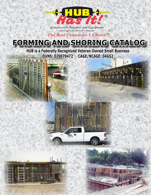
The Real Contractor’s Choice! R<br />
FORMING AND SHORING CATALOG<br />
HUB is a Federally Recognized Veteran Owned Small Business<br />
DUNS: 029079472 CAGE/NCAGE: 04GS2
HUB FORMING<br />
HUB <strong>Construction</strong> Specialties, Inc.<br />
CONCRETE FORMWORK ENGINEERING SERVICES<br />
Our engineering department will design all types of concrete <strong>form</strong>ing and shoring applications, temporary structures<br />
and custom steel fabrications to suite your specific project requirements and to provide solutions for all residential,<br />
commercial and heavy civil projects.<br />
HUB’s experienced engineering support allows the contractor to compete on larger projects by providing detailed<br />
concept drawings, erection and submittal drawings, computer generated under the supervision of a licensed<br />
professional engineer.
QUICK-FORM PANELS<br />
Description Weight<br />
2′ × 1′ QUICK-FORM PANEL 49 lb<br />
2′ × 2′ QUICK-FORM PANEL 38 lb<br />
3′ × 1′ QUICK-FORM PANEL 67 lb<br />
3′ × 2′ QUICK-FORM PANEL 95 lb<br />
3′ × 3′ QUICK-FORM PANEL 133 lb<br />
4′ × 1′ QUICK-FORM PANEL 86 lb<br />
4′ × 2′ QUICK-FORM PANEL 115 lb<br />
4′ × 3′ QUICK-FORM PANEL 155 lb<br />
4′ × 4′ QUICK-FORM PANEL 205 lb<br />
6′ × 1′ QUICK-FORM PANEL 120 lb<br />
6′ × 2′ QUICK-FORM PANEL 179 lb<br />
6′ × 3′ QUICK-FORM PANEL 242 lb<br />
6′ × 4′ QUICK-FORM PANEL 300 lb<br />
6′ × 6′ QUICK-FORM PANEL 450 lb<br />
8′ × 1′ QUICK-FORM PANEL 156 lb<br />
8′ × 2′ QUICK-FORM PANEL 234 lb<br />
8′ × 3′ QUICK-FORM PANEL 310 lb<br />
8′ × 4′ QUICK-FORM PANEL 395 lb<br />
8′ × 6′ QUICK-FORM PANEL 584 lb<br />
8′ × 8′ QUICK-FORM PANEL 758 lb<br />
8′ × 10′ QUICK-FORM PANEL 815 lb<br />
AADJUSTABLE FORM BRACKET<br />
Description Weight<br />
ADJUSTABLE FORM BRACKET 8.3 lb<br />
STRIPPER FORMS<br />
Description Weight<br />
8′ QF STRIPPER FORM 150 lb<br />
6′ QF STRIPPER FORM 114 lb<br />
4′ QF STRIPPER FORM 75 lb<br />
INSIDE CORNER<br />
Description Weight<br />
8′ QF INSIDE CORNER 224 lb<br />
6′ QF INSIDE CORNER 168 lb<br />
4′ QF INSIDE CORNER 112 lb<br />
3′ QF INSIDE CORNER 84 lb<br />
2′ QF INSIDE CORNER 56 lb<br />
QUICK-FORM PANELS<br />
ADJUSTABLE FORM<br />
BRACKET<br />
INSIDE CORNER FORM<br />
WALLFORMING<br />
STRIPPER FORMS<br />
4×3<br />
QUICK-FORM<br />
PANEL<br />
1
WALLFORMING<br />
INSIDE HINGED CORNERS<br />
Description Weight<br />
8′ QF INSIDE CORNER HINGED 240 lb<br />
6′ QF INSIDE CORNER HINGED 180 lb<br />
4′ QF INSIDE CORNER HINGED 120 lb<br />
3′ QF INSIDE CORNER HINGED 90 lb<br />
2′ QF INSIDE CORNER HINGED 60 lb<br />
INSIDE STRIPPING CORNERS<br />
Description Weight<br />
8′ QF STRIPPING CORNER 310 lb<br />
6′ QF STRIPPING CORNER 234 lb<br />
4′ QF STRIPPING CORNER 150 lb<br />
3′ QF STRIPPING CORNER 115 lb<br />
2′ QF STRIPPING CORNER 75 lb<br />
STRIPPING RATCHETS<br />
¾″ × 4″ COIL BOLT .55 lb<br />
¾″ HEX COL NUT .126 lb<br />
OUTSIDE CORNERS<br />
Description Weight<br />
8′ QF OUTSIDE CORNER 80 lb<br />
6′ QF OUTSIDE CORNER 60 lb<br />
4′ QF OUTSIDE CORNER 40 lb<br />
3′ QF OUTSIDE CORNER 30 lb<br />
2′ QF OUTSIDE CORNER 20 lb<br />
OUTSIDE HINGED CORNERS<br />
Description Weight<br />
8′ QF OUTSIDE CORNER HINGED 240 lb<br />
6′ QF OUTSIDE CORNER HINGED 180 lb<br />
4′ QF OUTSIDE CORNER HINGED 120 lb<br />
3′ QF OUTSIDE CORNER HINGED 90 lb<br />
2′ QF OUTSIDE CORNER HINGED 60 lb<br />
ADAPTER PANELS W/F.U. BOLTS<br />
Description Weight<br />
8′ ADAPTER PANEL TO UNIPLY 75 lb<br />
6′ ADAPTER PANEL TO UNIPLY 58 lb<br />
4′ ADAPTER PANEL TO UNIPLY 40 lb<br />
¾ × 6″ FIT-UP BOLT AND NUT 1 lb<br />
QUICK-FORM CORNERS<br />
OUTSIDE HINGED FORMS<br />
INSIDE HINGED FORMS<br />
OUTSIDE CORNER
CLAMPING DEVICES<br />
Description Weight<br />
QUICK-FORM CLAMP 9 lb<br />
QUICK-FORM JIMMY CLAMP 13 lb<br />
BULKHEAD CLAMP 4 lb<br />
SCAFFOLDING AND PIPEBRACING<br />
Description Weight<br />
QUICK-FORM WALKWAY BRACKET 28 lb<br />
SAFETY RAIL/WALKWAY BRACKET 8 lb<br />
½″ × 3″ BOLT (SAFETY RAIL) 0.18 lb<br />
4″ DEEP SCAFFOLD BRACKET 38 lb<br />
PIPE BRACE 7′ - 6″ TO 13′ - 0″ 64 lb<br />
PIPE BRACE 14′ - 0″ TO 23′ - 6″ 130 lb<br />
PIPE BRACE 22′ - 6″ TO 39′ - 0 208 lb<br />
PIPE BRACE ADAPTER PLATE 5 lb<br />
PIPE STAKE BRACE<br />
¾ × 6″ FIT-UP BOLT AND NUT 1 lb<br />
TAPER TIES & SHE-BOLTS<br />
Description Weight<br />
TAPER TIE 1.5 × 1.25 × 30″ 14 lb<br />
TAPER TIE 1.5 × 1.25 × 36″ 17 lb<br />
TAPER TIE 1.5 × 1.25 × 42″ 20 lb<br />
TAPER TIE 1.5 × 1.25 × 48″ 24 lb<br />
TAPER TIE 1.5 × 1.25 × 60″ 29 lb<br />
TAPER TIE 1.5 × 1.25 × 72″ 35 lb<br />
TAPER TIE PLASTIC PLUG 0.2 lb<br />
SHE BOLT 1.5 × 12″ 1″ COIL INNER 5.6 lb<br />
1.5 WING NUT 3.1 lb<br />
1.25 WING NUT 1.3 lb<br />
FLAT WASHER 5.4 lb<br />
DRY TIE BRACKET 3.1 lb<br />
¾ × 6″ FIT-UP BOLT AND NUT 1 lb<br />
5″ DOUBLE CHANNEL WALERS<br />
Description Weight<br />
5′ × 5″ DBL. CHNL. WALER 67 lb<br />
3′ × 5″ DBL. CHNL. WALER 41 lb<br />
QUICK-FORM ACCESSORIES<br />
QUICK-FORM JIMMY CLAMP<br />
ADJUSTABLE<br />
BULKHEAD CLAMP<br />
QUICK-FORM CLAMP<br />
PIPE BRACE<br />
TAPER TIE<br />
DOUBLE CHANNEL WALER<br />
WALLFORMING<br />
1
WALLFORMING<br />
J BOLT ASSEMBLY<br />
(price does not include plate washer)<br />
Description Weight<br />
¾″ × 9″ J BOLT ASSEMBLY 1.2 lb<br />
¾″ × 10″ J BOLT ASSEMBLY 1.5 lb<br />
¾″ × 12″ J BOLT ASSEMBLY 1.8 lb<br />
¾″ × 16″ J BOLT ASSEMBLY 2.3 lb<br />
⅜″ × 3″ × 6″ PLATE WASHER 2 lb<br />
LIFTING ACCESSORIES<br />
Description Weight<br />
QUICK-FORM GANG LIFTING LUG 35 lb<br />
BUNDLE LIFTER 45 lb<br />
SHAKEOUT CHAIN ASSY 35 lb<br />
QUICK PIN<br />
LANDING PLATFORM<br />
Description Weight<br />
SWING - ARM LANDING BKT. 160 lb<br />
SWING - ARM BOX - OUTS 5 lb<br />
MISCELLANEOUS<br />
Description Weight<br />
ALIGNMENT CLAMP 103<br />
1″ HEX COIL NUT 0.441<br />
STEP OUT BRACKET 14.5<br />
BASE CLIP 3<br />
¾″ × 12″ F.U. BOLT WITH RUNNING<br />
NUT<br />
QUICK-FORM ACCESSORIES<br />
1.63<br />
¼″ × 4″ × 5″ PLATE WASHER 1.46<br />
¾″ × 4 ½″ UNI-COIL ANCHOR 0.61<br />
¾″ × 6″ UNI-COIL ANCHOR 0.78<br />
UNI-COIL TANG<br />
PLUMBING SCREWS<br />
ADJUSTABLE SHEAR WALL<br />
BRACKET<br />
¾″ × 6″ STRT.COIL LOOP INSERT/<br />
CONE FAST<br />
J BOLT ASSEMBLY<br />
GANG LIFTING LUG<br />
ALIGNMENT CLAMP<br />
SHAKE OUT CHAIN<br />
ASSEMBLY<br />
BASE CLIP<br />
UNI-COIL ANCHOR & TANG
WALLFORMING<br />
QUICK-FORM 1
WALLFORMING<br />
Steel-Ply® Features<br />
Steel-Ply® is today’s superior <strong>form</strong>. The reinforced,<br />
high-carbon steel frame means edges stay straight<br />
and corners stay square, so panels are <strong>quick</strong>ly<br />
aligned and easily stacked. Built-in handles make<br />
moving and placing the panels easy, too.<br />
The long-lasting plywood facing have a heavyduty<br />
overlay and aluminum-filled polyurethane<br />
edge sealer to keep out moisture and prevent<br />
delamination and swelling. When needed, refacing<br />
is simple and inexpensive.<br />
All these factors combine to create a 1,000 psf<br />
rated system that will save you time in setup, last<br />
longer and give you better results.<br />
Panels and Fillers<br />
There are 80 sizes available for fast erection of<br />
virtually any layout by combining panel and filler<br />
sizes and erecting vertically or horizontally. This<br />
eliminates the sawing, drilling, measuring and nailing<br />
common with job-built <strong>form</strong>ing. Quick and easy<br />
handling, no tops, bottoms, lefts or rights makes for<br />
improved labor productivity.<br />
Steel-Ply® owners commonly report 200 to 300 reuses<br />
from panels and filler before re-ply is necessary.<br />
Special ½” HDO Plywood is edge-and surface-sealed<br />
to prevent determination and to prolong <strong>form</strong> life.<br />
Durable, high carbon steel frames are reinforced<br />
for rigidity and strength to surround and protect the<br />
plywood.<br />
No measuring or drilling for ties-dado slots are placed<br />
12″ on center and 6” from each end for tie insertion.<br />
STEEL PLY®
STEEL PLY®<br />
Wedge Bolt connections enable<br />
unskilled laborers to become<br />
consistently productive. No special<br />
tools are required, just a hammer.<br />
Wedge Bolts connect panels and<br />
capture ties at the same time.<br />
The Long Bolt similar to the Wedge<br />
Bolt, is used to connect the 1″, 1½″<br />
and 2″ steel filler to adjust panels and<br />
filler.<br />
With a shorter length and slot than a<br />
Wedge Bolt, the Short Bolt can be<br />
used to attach the pilaster <strong>form</strong> to a<br />
Steel-Ply <strong>form</strong>.<br />
The Base Tie Bolt secures either a panel tie or a flat tie<br />
to an end rail or a side rail (1) when resting on a footing, or<br />
(2)where panels butt against existing vertical surface.<br />
WALLFORMING<br />
1
WALLFORMING<br />
Waler Attachment<br />
Standard 2″ × 4″ or 2″ × 6″ lumber can be used as<br />
walers for the Steel-Ply® Forming System. With<br />
specially designed hardware, the walers are <strong>quick</strong>ly<br />
fastened to bring <strong>form</strong> work into alignment. Only one<br />
row of walers is required per tier of <strong>form</strong>s for handset<br />
applications.<br />
Job Built Filler<br />
Filling Angles provide a means to construct a<br />
custom size filler of ¾″ plywood that can be<br />
connected to side rails of adjoining <strong>form</strong>s.<br />
STEEL PLY®<br />
Strongback Attachment<br />
Additional tiers of <strong>form</strong>s will require strongbacks for<br />
vertical alignment of the <strong>form</strong> work. Strongbacks are<br />
required only on one side of the <strong>form</strong>s for handset<br />
hardware to make stacking easy.
STEEL PLY®<br />
Inside and Outside Corners<br />
Reusable steel corners, built to<br />
precise tolerances, minimize errors<br />
by eliminating measures, sawing<br />
and fitting. Both Inside and Outside<br />
Corners are available in five lengths<br />
and can be set with either end up or<br />
down to reduce the time and labor<br />
required.<br />
Bay Corners<br />
Standard 135 Inside and Outside<br />
Bay Corners simplify <strong>form</strong>ing. Attach<br />
them to Steel-Ply® panels and fillers<br />
with Wedge Bolts for <strong>quick</strong> and easy<br />
assembly. Inside and Outside Bay<br />
Corners are available in five standard<br />
lengths.<br />
Hinged Corners<br />
In most wall applications, Inside<br />
Hinged Corners are used opposite<br />
Outside Hinged Corners to achieve<br />
the desired angle. The Inside Hinged<br />
Corner may be used to <strong>form</strong> inside<br />
corners as narrow as 45º . The<br />
Outside HingedCorner will <strong>form</strong><br />
outside corners from 5º to 135º . Filler<br />
sizes needed to make up dimensions<br />
will vary depending on the angle being<br />
<strong>form</strong>ed.<br />
WALLFORMING<br />
1
WALLFORMING<br />
Scaffold Bracket<br />
The Steel-Ply® Scaffold Bracket assembly provides a<br />
safe access plat<strong>form</strong> for above-grade applications.<br />
The Scaffold Bracket is <strong>quick</strong>ly attached to <strong>form</strong><br />
work with a Wedge Bolt and the attached S-Wedge.<br />
Scaffold planking, toe boards and guard rails<br />
(by contractor) complete the work plat<strong>form</strong>.<br />
Note: Do not use the Scaffold Bracket to support<br />
concrete soffit <strong>form</strong>s or for temporary storage<br />
ofequipment and materials.<br />
STEEL PLY®<br />
Pilaster Forms<br />
Pilaster of less than 12 inches are <strong>form</strong>ed <strong>quick</strong>ly<br />
and easily using the Steel-Ply® Forming System<br />
and Pilaster Forms. The Pilaster Form eliminates<br />
the need for using inside and outside corners with<br />
specific filler sizes. Pilaster Forms can be used to<br />
<strong>form</strong> concrete pilasters from 1 to 12 inches deep in 1<br />
inch increments.<br />
Footing Corner Bracket<br />
Footing, pad and slab <strong>form</strong>ing with Steel-Ply is made easy<br />
with the Footing Corner Bracket and the Stake Plate. Two<br />
Footing Corner Brackets at each corner, one on top and one<br />
on the bottom hold the panels firmly, and at virtually any<br />
dimension that your job requires (2″ increments). The Stake<br />
Plates are then positioned along the top edge of the Steel-<br />
Ply panels as needed for steel stakes to hold the <strong>form</strong>s in<br />
place against the concrete pressure. Either ¾″ round or<br />
Ibeam steel stakes can be used with the Stake Plate. The<br />
Stake Plates can be located midway between Steel-Ply<br />
crossmembers and end rails to provide access for a stake<br />
puller.
WALLFORMING<br />
STEEL PLY® 1
WALLFORMING<br />
ALUMINUM BEAM GANGS<br />
Aluminum Beam Gang Form System offers unsurpassed<br />
<strong>form</strong>ing versatility and a host of unique features, benefits<br />
and advantages. At the heart of this system is our computeroptimized<br />
aluminum beam which features an extremely high<br />
strength-to-weight ratio. The Aluminum Beams or Joists are<br />
fastened to steel or aluminum walers by means of our unique<br />
beam attachment clamps.<br />
A suitable plywood is attached to the resulting rigid, compact<br />
and lightweight lattice to create the basic gang <strong>form</strong>. The<br />
use of any of <strong>Hub</strong> accessories enhances the versatility of<br />
the Aluminum Beam Gang Form to achieve a wide range<br />
of <strong>form</strong>ing conditions. Because <strong>Hub</strong> has several aluminum<br />
beam and waler sizes and three capacities of ties available<br />
for use on the Aluminum Beam Gang Forms, a wide variety<br />
of beam spacings and tie patterns can be utilized.<br />
LENGTH WT.(LBS.)<br />
3′-0″ 13.8<br />
4′-0″ 18.4<br />
5′-0″ 23.0<br />
6′-0″ 27.6<br />
7′-0″ 32.2<br />
8′-0″ 36.8<br />
9′-0″ 41.4<br />
10′-0″ 46.0<br />
11′-0″ 50.6<br />
12′-0″ 55.2<br />
13′-0″ 59.8<br />
14′-0″ 64.4<br />
15′-0″ 69.0<br />
16′-0″ 73.6<br />
18′-0″ 82.8<br />
20′-0″ 92.0<br />
22′-0″ 101.2<br />
24′-0″ 110.4<br />
26′-0″ 119.6<br />
28′-0″ 128.8
WALLFORMING<br />
ALUMINUM BEAM GANGS 1
WALLFORMING<br />
Flex-Form® gives you all the strength and versatility<br />
you need. Has 4″ deep vertical stiffeners with 3 ⁄16″<br />
steel skin plate to provide a 1000 psf system that<br />
handles any radius 5′ and over.<br />
Pre-Rolled Steel Ribs Set the Radius<br />
Rolled top and bottom ribs bolt to flexible panels to<br />
shape and securely hold the <strong>form</strong> in the radius you<br />
require. Panels con<strong>form</strong> precisely to the radius of<br />
the ribs - this design assures that you’ll get the correct<br />
radius every time. And with a straight rib, you can<br />
produce a straight wall if needed.<br />
Perfectly Smooth Concrete<br />
Because the steel skin plate flexes to <strong>form</strong> the<br />
desired arc, there’s no chording effect in the poured<br />
concrete surface. Conventional panel systems<br />
produce <strong>form</strong> joint marks that require grinding and<br />
rubbing. Flex-Form® produces smooth concrete<br />
surfaces that require little or no finishing labor.<br />
Fast and Simple Erection<br />
Panels are delivered to the job site pre-assembled<br />
to your required radius. There are no expensive<br />
templates to build; no need to torque bolts; just begin<br />
erection labor.<br />
If the job requires more than one radius, simply order<br />
extra rolled ribs for use with the same <strong>form</strong>s. Change<br />
over is <strong>quick</strong> and simple - done on the site by job<br />
personnel. The new rolled ribs will automatically set<br />
the new radius to the <strong>form</strong>s; this will speed assembly<br />
and increase <strong>form</strong>ing productivity.<br />
Stacking Panels<br />
Panels can be stacked by bolting the top and bottom<br />
ribs of adjacent <strong>form</strong>s with ¾″ fit-up bolts and nuts.<br />
Steel walkway brackets may also be bolted to the<br />
vertical stiffeners to provide vertical alignment. Pipe<br />
Form Aligners bolt directly to vertical stiffeners as well.<br />
FLEX-FORM®<br />
Specifications<br />
Skin plate thickness:<br />
3 ⁄16″<br />
Pressure rating: 1,000 psf<br />
Panel/filler heights: 2′, 3′, 4′, 5′, & 6′<br />
Width: Panels - 4′, 8′, & 12′<br />
Fillers - 4″, 6″ & 8″<br />
Approximate Weight: 20 psf (assembled)<br />
Thickness of panel: 4¼″<br />
Minimum radius: 5′
WALLFORMING<br />
FLEX-FORM® 1
WALLFORMING<br />
RISER FORM
The FormRight concrete <strong>form</strong>ing<br />
system is a modular design suitable<br />
in handset or gang<strong>form</strong> applications.<br />
Modular versatility<br />
Panels come in 23 different sizes and can be<br />
combined vertically or horizontally to create<br />
almost any dimension. A full line of accessories<br />
and hardware makes configuring gangs<br />
and setting details <strong>quick</strong> and simple.<br />
Rapid Clamps eliminate the need for walers<br />
even when moving large gangs. The Adjustable<br />
Aligning Clamp, Outer Corner Clamp and<br />
Strongback Clamp make panel connections for<br />
common details as fast and easy as standard<br />
panel connection.<br />
System strength<br />
FormRight panels are manufactured with rust<br />
resistant hot-dipped galvanized or dip painted<br />
steel frames. The <strong>form</strong> face is a 14 mm (½”)<br />
plywood with a phenolic resin overlay on both<br />
sides to provide a high quality concrete finish<br />
and extended panel life.<br />
Panels, clamps and ties are designed to withstand<br />
60 kN/m2 (1250 psf) of concrete pressure<br />
and are fully compatible with the Rasto<br />
<strong>form</strong>ing system.<br />
FORMRIGHT<br />
WALLFORMING<br />
1
WALLFORMING<br />
SOLDIER BEAM
MAX-A-FORM®<br />
Max-A-Form® is a gang <strong>form</strong> system that allows faster<br />
placement, pours and resetting. The strong, all-steel design allows <strong>form</strong>s<br />
to be set in larger units. Fewer crane picks are necessary and cycling<br />
time is optimized on repetitious pouring applications. Gang size is<br />
limited only by available crane capacity.<br />
Forms are assembled easily using ¾″ Speed Bolt and Nut. Panels are<br />
punched with enlonged holes in both the top and side framing, to allow<br />
easy alignment and <strong>quick</strong> assembly, regardless of panel orientation.<br />
Panels are available in more than 100 sizes, from 2′ wide by 1′ long to<br />
12′ wide 20′ long. The large number of filler choices allows more gang<br />
and detail flexibility. Large, 200 square foot panels mean fewer pieces,<br />
fewer panel joints and less labor to assemble.<br />
Versatile tie systems are available with capacities and configurations to<br />
maximize cost effectiveness for each application.<br />
Taper Ties and She-Bolts are used with Plate Washers or Cast Bearing<br />
Washers and nuts for efficient flat and battered wall applications.<br />
External top and bottom ties are available in several lengths and<br />
adjustment ranges to accommodate a wide range of wall thickness<br />
and special applications.<br />
Specifications:<br />
Skin Plate Thickness 3 ⁄16″<br />
Pressure Ratings 8′ width: 1,500 psf<br />
10′ width: 1,200 psf<br />
12′ width: 1,000 psf<br />
2′, 2.5′, 3′ 3.5′, 4′, 5′, 6′, 7′, 8′,<br />
Panel Width<br />
9′, 10′, 12′<br />
1′, 2′, 3′, 4′, 5′, 6′, 7′, 8′, 10′, 12′,<br />
Panel Length<br />
20′<br />
Approximate Weight 20 psf (assembled)<br />
Panel Thickness 6-½″ - 2′ to 7′ width<br />
8-½″ - 8′, 9′, 10′ width<br />
10-½″ - 12′ width<br />
Max-A-Form® For Large Columns<br />
For large columns that require a concrete finish with few seams, Max-<br />
A-Form is often the systems of choice. Max-A-Form columns up to 8′<br />
wide can be poured without the use of internal ties. The Max-A-Form<br />
system features a 3 ⁄16″ steel face for a consistently smooth finish, and<br />
panel heights of up to 20′. A heavy duty, 1500 psf rentable steel <strong>form</strong>ing<br />
system ideally suited for <strong>form</strong>ing square or rectangular bridge piers and<br />
columns. No matter what type of column contractors encounter, <strong>Hub</strong> has<br />
equipment that will help them <strong>form</strong> these common structural elements<br />
<strong>quick</strong>ly and cost-effectively.<br />
WALLFORMING<br />
1
WALLFORMING<br />
JAHN-A®<br />
Bracket is made of high strength steel with a<br />
cadmium plated eccentric and painted body which<br />
is rust resistant. Designed for use with single<br />
2×4 waler. Can be installed either before or after<br />
walersare in place. Can be used for any type of wall<br />
<strong>form</strong>sand may be used repeatedly.<br />
WT.(LBS.)<br />
1.4<br />
JAHN-C®<br />
Jahn C® bracket is used to attach vertical<br />
strongbacks for <strong>form</strong> work alignment. Designed for<br />
use with single 2×4 walers and 8-¼″ end. Eccentric<br />
securely holds <strong>form</strong> work while compensating for<br />
minorvariations in lumber sizes. Bracket can also be<br />
used to support a horizontal plywood joint.<br />
WT.(LBS.)<br />
2.0<br />
SNAPTIE SYSTEM<br />
JAHN® CORNERLOCK<br />
The Jahn cornerlock is used at outside corners to<br />
secure the 2×4 walers. Only two nails are needed<br />
for attachment, while barbed plates grip the side of<br />
the 2×4’s for positive non-slip action. The locking<br />
handle has a “Cam Action”, drawing the walers<br />
together at true right angles. No special tools are<br />
needed for either installation or stripping.<br />
WT.(LBS.)<br />
1.1<br />
JAHN® TIE EXTENDER<br />
Converts short end snapties to standard end<br />
snapties. With the Jahn® C bracket and 2×4’s,<br />
vertical strongbacks are possible at any point in the<br />
<strong>form</strong>.<br />
WT.(LBS.)<br />
0.2<br />
JAHN® SCAFFOLD JACK<br />
The all steel unit designed to fit 24″×24″, 16″×24″ tie<br />
and waler spacings. This jack has a built in guardrail<br />
receptacle and is designed to hold two 2×10 planks<br />
for a comfortable working plat<strong>form</strong>. Space jacks at<br />
8′-0″ maximum centers. Note: Snapties are not<br />
designed to carry scaffold bracket loads.<br />
DESCRIPTION WT.(LBS.)<br />
A-89 17.0
Liner Clamp<br />
Designed for use with a single 2×4 strongback for<br />
vertical <strong>form</strong> alignment, this liner clamp can be<br />
installed after erection of the <strong>form</strong>s and is not limited<br />
by <strong>form</strong>-tie spacing. Sturdy, galvanized construction<br />
reduces maintenance and replacement, and speedy<br />
installation reduces <strong>form</strong>ing costs. Strongbacks<br />
are used to align and not to strengthen <strong>form</strong>s.<br />
They are normally used on one side only, spaced<br />
6′ horizontally. Liner clamps should attach the<br />
strongback to every other single waler.<br />
WT.(LBS.)<br />
1.1<br />
Steel Wedge<br />
The steel tie holder is fabricated from high carbon<br />
steel and heat treated for added strength. Easily<br />
installed and removed; will not turn or fall off. 100<br />
pieces/carton.<br />
SIzE WT.(LBS.)<br />
¾″ 0.40<br />
1-⅛″ 0.40<br />
SNAPTIE SYSTEM<br />
WALLFORMING<br />
Panel Clip<br />
A thin, strong clip used primarily for adding extra<br />
height to <strong>form</strong> panels. A common use of the Panel<br />
Clip is as an aid to setting standard narrow filler<br />
panels horizontally on the top of a wall of <strong>form</strong><br />
panels. Standard wall ties can be used to tie the wall<br />
at the joint between the fillers and the normal wall<br />
panels. 50 pieces per carton.<br />
WT.(LBS.)<br />
0.47<br />
Waler Bracket<br />
Unsafe toenail connections can be eliminated and<br />
waler lumber saved by using this bracket. Fasten<br />
to studs with double head nails, insert walers and<br />
secure with Steel Wedge. Normal spacing 4′ on<br />
center. Available in one size for 2×4′s.<br />
WT.(LBS.)<br />
0.87<br />
1
WALLFORMING<br />
Jahn® Forming System<br />
Preparation:<br />
Gang drilling the plywood is the only preparation<br />
required. Holes need to be drilled ⅛″ larger than the<br />
snap tie head. Normally a 9 ⁄16″ diameter drill bit will<br />
be required. We recommend you drill a maximum 5<br />
plywood panels.The ⅝″ take-up of the eccentric on the<br />
Jahn “A” Bracket allows a snap tie with a L&W dimension<br />
of 4-¾″ to be used with a ⅝″ or ¾″ plywood. The ⅝″<br />
take-up on the “C” bracket allows it and 8¼″ snap ties to<br />
be used on ⅝″ plywood.<br />
SNAPTIE SYSTEM<br />
Snaptie Spacing and Rate Placement:<br />
The most common snap tie spacings being used with the Jahn Forming System are shown below. For different<br />
rates or pour and/or other tie spacing, contact Masons Supply. Refer to the back cover for addresses and<br />
phone numbers.<br />
Plywood Used Strong Way (Face Grain Parallel to Spacing)<br />
Notes: The above recommendations are based on the use of ¾″ Ply<strong>form</strong> Class I, and 2×4 S4S studs (Douglas Fir-<br />
Larch, Southern Pine or equal having a minimum allowable fibre stress of 1,200 psi). Design is based on all <strong>form</strong>work<br />
members being continuous over four or more supports. Normal weight concrete made with type 1 cement, no<br />
admixtures or pozzolan, slump no more than 4 inches and vibration limited to 4 lineal feet or less.
Jahn® Forming System (cont)<br />
Footing Plates:<br />
Good <strong>form</strong>ing practices require that a level footing be<br />
used as a starting point for all <strong>form</strong>ing applications.<br />
Snap a chalk in back of the plywood thickness and nail<br />
down a 2×4 plate.<br />
Installation of Snapties and “A” Brackets:<br />
Place the ends of the Snapties through the holes<br />
in the plywood. The 4¾″ L&W Snaptie, Standard is<br />
recommended for use with the Jahn “A” Brackets, ⅝″ or<br />
¾″ plywood and 2×4 wales.<br />
Two workmen can install the snap ties with speed and<br />
economy. One inserts the tie through the tie hole and<br />
the other attached the “A” bracket.<br />
SNAPTIE SYSTEM<br />
WALLFORMING<br />
Plywood Panel Erection:<br />
Erect, plumb, nail to plate and temporary brace<br />
the first sheet of plywood.<br />
Erect additional sheets of plywood by nailing<br />
them to the 2×4 plate and temporary wood<br />
cleats at the top corners. Make sure the joints<br />
are tight. If panels are to be stacked, ensure that<br />
the panel tops are level.<br />
1
WALLFORMING<br />
Jahn® Forming System (cont)<br />
Installation of Wales:<br />
Install the Walers into the brackets working from top to<br />
bottom of the panel and tightening the eccentric as you<br />
go. Waler joints should occur at a bracket or a scab<br />
should be utilized to reinforce the joint (see sketch).<br />
SNAPTIE SYSTEM<br />
Inside Wall Panel Erection:<br />
The inside panel sequence is the same as the outside<br />
panel described above except for the placement of<br />
the plywood panels over the tie ends. This can be<br />
accomplished by two workmen by starting at the bottom<br />
and moving the panel from side to side and up and down<br />
to align the snap ties with the holes in the plywood.
Jahn® Forming System (cont)<br />
Inside Corner Forming:<br />
No special treatment is required for inside corners other<br />
than the alternating of the wales as shown in the sketch.<br />
It is advantageous to start the inside corners with full<br />
size plywood panels to facilitate <strong>form</strong>ing the outside<br />
corners.<br />
Outside Corner Forming:<br />
Install the first outside panel in line with the first inside<br />
panel.Filler panels, the same thickness as the wall<br />
plus the plywood thickness, are then used to fill out the<br />
exterior corner.<br />
Installation of Jahn Cornerlock:<br />
The cornerlock eliminates costly overlapping and<br />
blocking of the wales. Its cam action draws the wales<br />
securely together. Place one wale flush at the corner<br />
and let the other extend past the flush one. Slip the<br />
cornerlock into place with the handle perpendicular to<br />
the wale. Nail the cornerlock in place and rotate the<br />
handle 90° toward the wale. A snug, tight outside corner<br />
is accomplished.<br />
Installation of Strongbacks:<br />
Strongbacks are used to aid in <strong>form</strong> alignment and to tie<br />
stacked panels together. Loose 2×4’s are used in<br />
conjunction with Jahn “C” Brackets and 8¼″ L&W snap<br />
ties or 4¾″ L&W snap ties with the Jahn Tie Extenders<br />
to strongback the <strong>form</strong>s. Normal strongback spacing is<br />
8′-0″ on center.<br />
SNAPTIE SYSTEM<br />
WALLFORMING<br />
1
WALLFORMING<br />
SNAPTIE SYSTEM<br />
Jahn® Forming System (cont)<br />
Joint Cover Details:<br />
Alternate A - Drill 9 ⁄16″ diameter hole 1⅛″ down from<br />
top edge of the lower sheet of plywood. Install snap<br />
tie, “A” Brackets and wale and then the upper sheet of<br />
plywood. Nail the upper sheet of plywood to the wale.<br />
Alternate B - Install snap tie in the joint between the<br />
panels. Add double wales and a “C” Bracket.<br />
Alternate C - Nail 4×4 wale to lower sheet of plywood,<br />
hold the wale in place with strongbacks and add<br />
upper sheet of plywood.<br />
Installation Of Second Lift Of Plywood:<br />
Lift the plywood sheet and place it into position. Hold<br />
the sheet in place with a short 2×4 spacing block,<br />
snap tie and “C” Bracket placed toward the top of<br />
the panel and nail the bottom of the sheet to the joint<br />
cover wale.<br />
Set additional panels by nailing them to the joint<br />
cover wale and securing them to the previous panel<br />
with a small wood cleat.<br />
Install the snapties, brackets and wales - working<br />
bottom to top.<br />
Note: Snap ties are not designed to carry scaffold<br />
bracket loads.
ALUMINUM SHORING SYSTEMS<br />
We manufacture aluminum, heavy load frame<br />
shoring systems with Safe Working Load (SWL)<br />
ranges from 24,000 lbs. to 50,000 lbs.<br />
Our 12 KIP Aluminum Shoring system is the most<br />
advanced shoring system in North America and is<br />
rapidly gaining popularity around the world.<br />
MODULAR ALUMINUM SHORING<br />
Our 25K Modular Aluminum Shoring system is a<br />
versatile, demountable system. The inside panel<br />
ledgers can be simply and <strong>quick</strong>ly removed from<br />
the frame, converting the legs into post shores.<br />
The same ledgers can be used with two lighter<br />
capacity legs (10K, 16K) of the same design.<br />
This feature enables inventory to be kept to a<br />
minimum, with reduction in storage area. The<br />
speed of assembly enables shipping costs to<br />
be dramatically reduced from the factory or long<br />
hauls.<br />
Our Modular Shoring Systems are available in 10<br />
kip, 16 kip and 25 kip sizes to handle just about<br />
any sized job, no matter how big or small.<br />
ALUMINUM POST SHORES<br />
Our Aluminum Post Shores, part of our modular<br />
shoring system are available without the<br />
demountable ledgers in 10 kip, 16 kip and 25<br />
kip capacities and can be constructed in custom<br />
length for specific applications.<br />
STEEL POST SHORES<br />
We also carry a line of Steel Post Shores for our<br />
customer’s needs.<br />
ALUMINUM SHORING<br />
SHORING<br />
2
SHORING<br />
ALUMINUM BEAMS AND STRINGERS<br />
Significant labor and material savings are being<br />
achieved by contractors using Hi-Lite Aluminum<br />
Beams and Stringers. When compared to<br />
wood solutions, the aluminum beams eliminate<br />
as much as ⅓ of the horizontal members,<br />
combined with up to 50% reduction in vertical<br />
supports.<br />
In addition to the labor savings realized because<br />
of fewer structural members, the reduced<br />
weight of the beams minimizes worker fatigue<br />
and strain, and improves worker efficiency, as<br />
aluminum beams are very easy to handle.<br />
These advantages become even more apparent<br />
as shoring height increases.<br />
ALUMINUM TELESCOPIC FLY FORMS<br />
Hi-Lite’s Aluminum Fly Form is the most efficient<br />
fly <strong>form</strong>ing system available. Its telescopic<br />
modular concept reduces the skilled manpower<br />
required for assembly and use.<br />
Our telescopic fly <strong>form</strong>ing system is capable<br />
of flying from one floor to the next without<br />
using large cumbersome lowering jacks, and is<br />
ideally suited for any multi-storey application.<br />
Condominiums, apartments, townhouses, large<br />
bay shopping malls, below grade structures and<br />
tunnels can be constructed with reduced cycle<br />
time and crane time and minimized material<br />
waste such as filler strips.<br />
ALUMINUM SHORING<br />
ALUMINUM BEAM WALL FORMS<br />
We manufacture three separate styles of wall<br />
<strong>form</strong>s, which range from all aluminum - to a<br />
combination of aluminum and plywood, either<br />
hand set or gang <strong>form</strong>ed with specially designed<br />
aluminum beam strongbacks<br />
.<br />
The use of these aluminum components allows<br />
strength where required while realizing savings<br />
in weight, labor, crane time and employee<br />
fatigue. Hi-Lite’s Aluminum Beam Wall Forms<br />
can be constructed from a variety of our<br />
different Aluminum Beams and Strongbacks.<br />
OTHER PRODUCTS AND ACCESSORIES<br />
We also manufacture Aluminum Access Truss<br />
Systems and just about everything else you<br />
need to keep your job site safe, including things<br />
like steel scaffolding and stairs access barriers.<br />
Some of our many other products include:<br />
• Aluminum Access Truss Systems<br />
• Aluminum Plywood Decks<br />
• Steel Scaffolding Frames and Accessories<br />
• 610 mm (24″) Screw Jack for Scaffolding<br />
Systems<br />
• Slab-Grab Guard Rail Post<br />
• Galvanized Crowd/Traffic Control Barrier<br />
• Mini Beam Column Form<br />
• Tie Rods<br />
• Mobile “Baker” Scaffold<br />
Contact us for your shoring needs.
FrameFast Shoring Frames<br />
FrameFast Shoring Frames are rated for<br />
12,000 Ibs. safe load per leg, up to two tiers<br />
high. Of course this load will be increased or decreased<br />
depending on the actual number of tiers<br />
used and total extension of the jacks. Refer to<br />
layout drawings for maximum shore leg capacities.<br />
This frame can be adapted to virtually any<br />
shoring condition, through the use of other accessories.<br />
There are eight standard sizes of frames<br />
available. Both 2′ and 4′ wide frames have the<br />
same load capacity.<br />
Crossbrace locking devices, which are a part<br />
of the frame, permits FrameFast Shore Frames<br />
to be erected and dismantled <strong>quick</strong>ly. It locks<br />
in position up to two crossbraces and one<br />
spacer bar. This unique locking arrangement<br />
securely holds the frames together, providing<br />
tower rigidity and safety.<br />
Meter Screw Jack<br />
The screw jacks are used for leveling, fine<br />
adjustment in elevation, and stripping clearance.<br />
The Meter Screw Jack is a full meter (39-⅜″) in<br />
length with 1.9″ OD, and provides a maximum<br />
extension of 27-⅜″,longest in the industry. As<br />
a result, total adjustment range is 25-¼″, from<br />
2-⅛″ to 27-⅜″.<br />
An 8″ × 8″ base plate is welded to the jack as<br />
a unit, so the jack can be used at top of the<br />
shore leg or at bottom. The plate has four holes<br />
which are used to clamp the W 8 × 10 stringer<br />
using the Versi<strong>form</strong> Friction Clamp, or Aluminum<br />
Attachment Clip. These holes are also used to<br />
attach the 8″ × 8″ U-Head Adapter.<br />
SHORING STEEL<br />
SHORING<br />
2
SHORING<br />
DECKFAST<br />
DeckFast, <strong>form</strong>erly Topec Deck System, is a modular slab <strong>form</strong>work system that is used for commercial and<br />
industrial applications. The system will support slabs up to 22″ and heights up to 19′ above the floor or ground.<br />
The basic DeckFast system consists of tubular post shores that are adjustable to 18′, bearing supports and modular<br />
<strong>form</strong>ing panels. The uniqueness of this system lies with bearing supports that capture and support corner clusters<br />
of four panels. When the bearing supports are fastened to flat top post shores, the panels and post shores can be<br />
erected individually from below, simplifying the erection process.<br />
The easy-to-use DeckFast system, with two basic components and two support rods, can be erected with a<br />
minimal amount of training. Even workers who are not familiar with the system can achieve high production rates<br />
per worker per day.<br />
Even infill sections can be easily <strong>form</strong>ed and economically installed using DeckFast components.<br />
Forming panels are made from 5-ply bonded veneers with 10 mm plywood. Edges are protected by specially<br />
designed powder-coated aluminum framing members that not only minimize the gap between panels but also<br />
add to panel strength. Powder-coated aluminum frames minimize maintenance cleaning efforts and reduce<br />
cleanup costs.<br />
Standard DeckFast Panel size is a nominal 5.9′ × 5.9′ (34.8 ft²) but weighs only about 100 lbs. Other sizes are also<br />
available to fit your needs.<br />
Typical Application
Basic Components<br />
Panel<br />
All panel frames are lightweight aluminum and are powdercoated<br />
to reduce cleaning. Sizes include:<br />
SIzE<br />
180 x 180 cm* (6′ × 6′ nominal)<br />
180 x 90 cm* (6′ × 3′ nominal)<br />
180 x 75 cm* (6′ × 2′-6″ nominal)<br />
180 x 60 cm* (6′ × 2′ nominal)<br />
180 x 45 cm* (6′ × 1′-6″ nominal)<br />
Post Shore<br />
350 and 550 Post Shores are completely galvanized inside and<br />
out including external threads. A built-in stop prevents removal<br />
of inner tube.<br />
SIzE<br />
350: L = 6′6″ - 11′5″ nominal<br />
550: L = 10′1″ - 18′ nominal<br />
Inner tube diameter: 2.45″ nominal<br />
Outer tube diameter: 3″ nominal<br />
All shores are complete with <strong>quick</strong>-release pins. One tap with the<br />
hammer is usually enough to release the shore from its load.<br />
Bearing<br />
The support for the DeckFast Panels is inserted into the steel<br />
shore and secured with an integrated T-Spring Bolt or Bearing<br />
Retainer.<br />
Edge Support Bearing<br />
It is inserted into the shore like the DeckFast Bearing. The Edge<br />
Support facilities flush connections of the DeckFast Panels along<br />
side walls.<br />
Assembly Aids<br />
Post Shore Tripod<br />
The Post Shore Tripod is designed for steadying the 350 and 550<br />
Post Shores during erection procedures (maximum 3″ diameter<br />
post).<br />
The Hinged design accommodates all angular patters, such as<br />
90°, 180°, and 360°.<br />
DF Erection Rod<br />
Facilitates the erection and disassembly of the DeckFast Panels.<br />
For ceiling heights up to 3.65 m (12’-0” nom.) Adjustable in steps<br />
of 5 cm (2”).<br />
DECKFAST<br />
180 × 180 Panel<br />
SHORING<br />
350 Post Shore 550 Post Shore<br />
Bearing Edge Support Bearing<br />
Post Shore Tripod<br />
DF Aluminum Erection Rod<br />
2
SHORING<br />
POST SHORES<br />
Medium Duty<br />
The Medium Duty Post Shore is a single piece load carrying device with a built-in adjustment feature<br />
to facilitate handing without sacrificing convenience. It can be used by itself or in combination with<br />
shoring frame system.<br />
• Safety factor of 3:1.<br />
• Fitted with <strong>quick</strong> release stripping pin for easy assembly and dismantling.<br />
• Hot dip galvanized comes standard.<br />
POST SHORE 350 POST SHORE 550<br />
Range 6′-6″ to 11′-5″ 10′-1″ to 18′0″<br />
Weight 46.5 lbs. 74.2 lbs<br />
Height Load Ratings (lbs.)<br />
9′ 6,400 --<br />
10′ 5,600 8,800<br />
11′ 4,300 8,000<br />
12′ -- 6,700<br />
13′ -- 5,700<br />
14′ -- 4,800<br />
15′ -- 4,100<br />
16′ -- 3,500<br />
17′ -- 3,100<br />
18′ -- 2,700
GUARD RAIL / SLABGRABBER<br />
The A-93 Adjustable Safety Guard Rail Bracket<br />
exceeds O.S.H.A. requirements (Section<br />
1926.500). The top and middle railing supports<br />
accept 2×4’s while the bottom adjustable toe<br />
board is designed to accept double or single<br />
1×6’s or 1×8’s.<br />
The bracket clamps securely from the top side<br />
of the floor and tightens easily with the built-in<br />
handle on the locking rod. Will fit any slab from<br />
3″ to 36″ in thickness.<br />
SHORING<br />
2
COLUMN FORMING<br />
Steel Ply<br />
The Real Contractor’s Choice! R
Steel Ply<br />
COLUMN FORMING<br />
Columns are common features in concrete construction projects and there are several ways that they can be <strong>form</strong>ed<br />
with modular systems. When helping contractors choose the best system for a particular application, it is important to<br />
maximize equipment utilization based on <strong>form</strong> reuse. It is also necessary to consider the column dimensions, rate of<br />
pour and the required concrete finish to select the most appropriate equipment.<br />
Standard Steel-Ply® Without ties<br />
Any size column up to 24″ wide can be <strong>form</strong>ed without ties<br />
by using standard Steel-Ply panels or fillers. Columns can<br />
be handset with standard outside corners. Handsetting<br />
<strong>form</strong>s is productive for projects with just a few columns or<br />
columns with varying dimensions.<br />
Columns can be also gang<strong>form</strong>ed with a Column Hinge<br />
and a release corner for greater productivity. Quick Column<br />
Hardware is used in combination with the Column Hinge to<br />
provide a <strong>quick</strong> closure and release. This method of column<br />
<strong>form</strong>ing with Steel-Ply virtually eliminates lost hardware<br />
and also provides maximum <strong>form</strong>ing productivity, though<br />
you need a crane to move the equipment.<br />
Steel-Ply® Ganged Column Hardware<br />
Column Hinges are used to hinge <strong>form</strong>s during setting<br />
and stripping. Quick Column Hardware, used opposite<br />
the Column Hinges, allowed the <strong>form</strong>s to be opened with<br />
hardware still in place. Used together, this column hardware<br />
speeds column productivity and increases labor productivity.<br />
3
COLUMN FORMING<br />
Steel Circular Column Forms<br />
Heavy duty, all-steel Circular Forms provide consistently<br />
round, smooth concrete columns for building and bridge<br />
construction. Look at the comprehensive features of these<br />
Column Forms:<br />
• A 3,000 psf pressure rating allows for fast pour<br />
rates.<br />
• Wide variety of standard sizes available for<br />
rental or purchase. Sizes include:<br />
• Diameters: 24″, 30″, 36″, 42″, 48″, 54″, 60″,<br />
72″, 84″ & 96″<br />
• lengths: 1′, 2′, 4′, 8′ and 10′ (bolt together for<br />
desired height)<br />
• Other diameters and lengths for special<br />
conditionsare always available for purchase.<br />
CIRCUlAR Steel<br />
• Versatility allows Circular Column Forms to<br />
bolt to Steel-Ply®, Max-A-Form® and Flex-<br />
Form® Forming Systems. Flex-Form fillers allow<br />
attachment to Versi<strong>form</strong>®.<br />
• Accessories include ¾″ Speed Bolts and Nuts<br />
for fast connections; lifting lugs for safe crane<br />
handling; bolt on ladders for worker access; and<br />
stripping wedges for fast cycling.<br />
• There is an extremely low maintenance cost,<br />
and the cost per <strong>form</strong>ed column is less than with<br />
other type column <strong>form</strong>s after only moderate<br />
reuse.
COLUMN FORMING<br />
MFG FIBeRGlASS COlUMN FORMS<br />
MFG One Piece Round Coulumn Forms have only one vertical seam, are supplied with<br />
bracing collars and “fast” bolts, and are available on a sale or rental basis. Diameters<br />
range from 12″ to 48″ are available in one piece lengths up to 20′ long.<br />
3
COLUMN FORMING<br />
SCISSOR ClAMP<br />
Scissor Clamp<br />
Used for columns of net concrete size<br />
from 10-½″ to 40″. Clamps are adjustable<br />
to fractions of an inch, no blank<br />
spots. Clamps are complete so no needless<br />
delays. Hammer is only tool needed<br />
to tighten and remove.They open<br />
either way, either side up and automatically<br />
squares the column.Pin and Chain<br />
Assembly<br />
Pin and Chain Assembly<br />
DeSCRIPtION Wt.(lBS.)<br />
10-½″ TO 22″ 40.0<br />
16″ TO 40″ 56.0<br />
Pin & Chain Replacement 1.0
For square and rectangular columns.<br />
Eliminate Back-up Stringers — Econ-O-Clamps are<br />
designed to exactly balance the strength of ¾″ plywood,<br />
thus cutting costs by eliminating back-stringers and<br />
simplifying erection.<br />
Automatically Squares Column — Econ-O-Clamps<br />
work just like a square to insure perfectly square <strong>form</strong><br />
assembly every time.<br />
No Special Tools — A hammer is all that’s needed to<br />
set or strip Econ-O-Clamps.<br />
No Measuring — Notches on one-inch centers size<br />
column exactly.<br />
Speeds Erection — Just nail one-half of an Econ-O-<br />
Clamp in position, then place the other half over it and<br />
clamp it set.<br />
Specifications — Heavy-Duty Econ-O-Clamps are<br />
manufactured in three sizes of high carbon steel angles<br />
electrically welded and coated to prevent rusting.<br />
NO. SIZe<br />
FORMS<br />
COlUMNS (eA. PC.))<br />
eCON-O-ClAMPS®<br />
WeIGHt<br />
PeR Set<br />
990104 24″ 8″×8″ thru 24″×24″ 21 lbs.<br />
990105 30″ 8″×8″ thru 30″×30″ 33 lbs.<br />
990106 36″ 8″×8″ thru 36″×36″ 39 lbs.<br />
COLUMN FORMING<br />
3
BOX CULVERT<br />
The Box Culvert Traveler is a fast, reusable traveler<br />
system that can be stripped as one unit and moved on<br />
its own wheels to the next pour. No additional accessories<br />
are required for setting, stripping, or moving.<br />
The Box Culvert Traveler design utilizes steel headers<br />
and uprights to create the complete frame. Jacks,<br />
turnbuckles and a deck slip plate are integrated into the<br />
frame design to facilitate stripping. Large 10″ diameter<br />
wheels make the entire assembly easy to move.<br />
BOX CULVERT<br />
The Box Culvert Traveler can be used with Steel-Ply®,<br />
Versi<strong>form</strong>®, Aluminum Beam Gang and Max-A-Form®<br />
<strong>form</strong>ing systems. Forms are attached to the traveler frame<br />
for the inside wall, and gang <strong>form</strong>s are used for the outside.<br />
High capacity ties are typically used to improve tie spacing<br />
and reduce labor costs.
BOX CULVERT<br />
BOX CULVERT<br />
4
BOX CULVERT<br />
MAX-A-FORM®<br />
Max-A-Form® is a gang <strong>form</strong> system that allows faster<br />
placement, pours and resetting. The strong, all-steel design allows <strong>form</strong>s<br />
to be set in larger units. Fewer crane picks are necessary and cycling<br />
time is optimized on repetitious pouring applications. Gang size is<br />
limited only by available crane capacity.<br />
Forms are assembled easily using ¾″ Speed Bolt and Nut. Panels are<br />
punched with enlonged holes in both the top and side framing, to allow<br />
easy alignment and <strong>quick</strong> assembly, regardless of panel orientation.<br />
Panels are available in more than 100 sizes, from 2′ wide by 1′ long to<br />
12′ wide 20′ long. The large number of filler choices allows more gang<br />
and detail flexibility. Large, 200 square foot panels mean fewer pieces,<br />
fewer panel joints and less labor to assemble.<br />
Versatile tie systems are available with capacities and configurations to<br />
maximize cost effectiveness for each application.<br />
Taper Ties and She-Bolts are used with Plate Washers or Cast Bearing<br />
Washers and nuts for efficient flat and battered wall applications.<br />
External top and bottom ties are available in several lengths and<br />
adjustment ranges to accommodate a wide range of wall thickness<br />
and special applications.<br />
Specifications:<br />
Skin Plate Thickness 3 ⁄16″<br />
Pressure Ratings 8′ width: 1,500 psf<br />
10′ width: 1,200 psf<br />
12′ width: 1,000 psf<br />
2′, 2.5′, 3′ 3.5′, 4′, 5′, 6′, 7′, 8′,<br />
Panel Width<br />
9′, 10′, 12′<br />
1′, 2′, 3′, 4′, 5′, 6′, 7′, 8′, 10′, 12′,<br />
Panel Length<br />
20′<br />
Approximate Weight 20 psf (assembled)<br />
Panel Thickness 6-½″ - 2′ to 7′ width<br />
8-½″ - 8′, 9′, 10′ width<br />
10-½″ - 12′ width<br />
Max-A-Form® For Large Columns<br />
For large columns that require a concrete finish with few seams, Max-AForm<br />
is often the systems of choice. Max-A-Form columns up to 8’ wide can be<br />
poured without the use of internal ties. The Max-A-Form system features<br />
a 3 ⁄16″ steel face for a consistently smooth finish, and panel heights of up to<br />
20’. A heavy duty, 1500 psf rentable steel <strong>form</strong>ing system ideally suited for<br />
<strong>form</strong>ing square or rectangular bridge piers and columns. No matter what<br />
type of column contractors encounter, <strong>Hub</strong> has equipment that will help them<br />
<strong>form</strong> these common structural elements <strong>quick</strong>ly and cost-effectively..
MIKE BRACKET<br />
ONE SIDED<br />
FORMING<br />
5
ONE SIDED<br />
FORMING<br />
Soldier Beam for use in <strong>form</strong>ing and construction<br />
were developed in England years ago to reduce<br />
the need for scarce and high-priced lumber. They<br />
were brought to the U.S. and improved upon when<br />
the same conditions appeared in this construction<br />
market.<br />
Symons has improved on the original design to<br />
produce the “next generation”, the most versatile,<br />
compatible construction beam system available.<br />
Soldiers are a strong, lightweight construction beam<br />
system with unlimited application possibilities. They<br />
are truly the “next generation” because of their<br />
unique hole patterns which make them adaptable to<br />
almost any configuration. When used in conjunction<br />
with their accessories, Soldiers can be braces,<br />
horizontal shore, vertical shores, strongbacks,<br />
walers, cantilever stiffbacks, trusses and many other<br />
<strong>form</strong>ing components.<br />
Soldiers are compatible with all Symons Forming<br />
Systems. They can be the waler and strongback<br />
system for Steel-Ply®, or Versi<strong>form</strong>®; they can be<br />
the one-sided bracing or cantilever stiffbacks for<br />
Max-A-Form®; they can be the truss and shoring for<br />
custom applications.<br />
SOLDIER BEAM<br />
Soldiers are double, 9″, specially <strong>form</strong>ed channels<br />
of 10 gauge, high strength steel. The end plates are<br />
perpendicular to the channels. When bolted together<br />
end-to-end with four ¾″ × 2″ Speed Bolts, the<br />
Soldiers become a straight, continuous beam which<br />
develops its full strength through the connection.<br />
Hole patterns in all faces of the channels and in<br />
the end plates accommodate the accessories and<br />
permit assembly in many configurations.<br />
Soldiers are lightweight and strong. They are<br />
as light as double 5″ channels and as strong as<br />
double 8″ channels.The engineering data confirms<br />
the impressive strength to-weight ratio of Symons<br />
Soldiers.<br />
Soldiers Feature:<br />
• Unique hole pattern permits a wide variety<br />
of assembly configurations.<br />
• All accessories bolt to the Soldier with<br />
¾″ × 2″ Speed Bolt.<br />
• Soldier is fabricated with strong, but<br />
lightweight 50 ksi steel.<br />
• Accessories are bolted directly to the<br />
Soldier at any point along web.<br />
• End-to-end connection provides same<br />
moment capacity as beam.<br />
• A complete line of accessories and<br />
hardware are available.
SOLDIER BEAM<br />
ONE SIDED<br />
FORMING<br />
5
ONE SIDED<br />
FORMING<br />
LENGTH CAPACITY<br />
2′ - 0″ 37.3 kips<br />
↓ ↓<br />
12′ - 0″ 37.3 kips<br />
13′ - 0″ 37.1 kips<br />
14′ - 0″ 36.8 kips<br />
15′ - 0″ 36.3 kips<br />
16′ - 0″ 35.5 kips<br />
17′ - 0″ 34.3 kips<br />
18′ - 0″ 32.9 kips<br />
19′ - 0″ 31.2 kips<br />
20′ - 0″ 29.4 kips<br />
21′ - 0″ 27.7 kips<br />
22′ - 0″ 26.3 kips<br />
23′ - 0″ 25.1 kips<br />
24′ - 0″ 24.1 kips<br />
25′ - 0″ 23.3 kips<br />
26′ - 0″ 22.7 kips<br />
27′ - 0″ 22.2 kips<br />
28′ - 0″ 21.8 kips<br />
29′ - 0″ 21.5 kips<br />
30′ - 0″ 21.1 kips<br />
31′ - 0″ 20.8 kips<br />
32′ - 0″ 20.4 kips<br />
33′ - 0″ 20.0 kips<br />
34′ - 0″ 19.5 kips<br />
35′ - 0″ 18.8 kips<br />
36′ - 0″ 18.1 kips<br />
37′ - 0″ 17.2 kips<br />
38′ - 0″ 16.3 kips<br />
39′ - 0″ 15.3 kips<br />
40′ - 0″ 14.3 kips<br />
SOLDIER BEAM<br />
SOLDIERS AS A POST SHORE<br />
GENERAL NOTES:<br />
All loads include a 3 to 1 factor of safety.<br />
Load capacities are based on 12″ strut jack extension.<br />
Gangs shorter than 28′-0″ did not vary more than ⅜″ in<br />
straightness.<br />
Gangs 28′-0″ and longer did not vary more than 1″ in<br />
straightness.<br />
Post shore should be plumb to ⅛″ in 3′-0″ or 2″ total.<br />
Whichever is less.<br />
All post shore lengths are unbraced.<br />
Brace as required for erection purposes and stability.<br />
Reference diagram for orientation of strut jack to the<br />
strong axis of the soldier.
SOLDIER BEAM<br />
WALER/SOLDIER BEAM COMPARISON<br />
ONE SIDED<br />
FORMING<br />
5
HUB FORMING<br />
FOR YOUR RENTAL<br />
NEEDS CALL<br />
HUB
The Real Contractor’s Choice! R<br />
HUB FORMING
TILT UP<br />
Ground release II lIftInG system*<br />
*U.S. Patent No. 4,703,595; 4,368,914 and 4,769,960<br />
The Ground ReleaseII System is designed to <strong>quick</strong>ly and efficiently lift and handle tilt-up panels and to be easily<br />
released from the ground. Ladders are seldom required when using this system.<br />
The Dayton/Richmond T-41 Ground ReleaseII System<br />
Insert consists of a hot forged anchor, plastic support<br />
base and a plastic recess plug. The anchor permits<br />
rapid hardware attachment and allows smooth rotation<br />
of the panel during the lifting sequence. Insert height is<br />
determined by panel thickness. Insert sizes other than<br />
those shown in the Chart below are available on special<br />
order. Special order inserts are furnished with a plastic<br />
tipped wire base rather than the standard wire base.<br />
Ground ReleaseII Inserts are shipped assembled, ready to<br />
use and are sized ⅛˝ less than panel thickness.<br />
to order: Specify: (1) quantity, (2) name, (3) panel<br />
thickness, (4) bottom face exposed aggregate or <strong>form</strong> liner<br />
thickness.<br />
example: 150, T-41 Ground ReleaseII Inserts, 6″ panel<br />
with ¾˝ bottom face exposed aggregate.<br />
t-41 Ground releaseII Insert<br />
Warning! SWL provides a safety factor of approximately 2 to 1 in 2,500 psi weight concrete.<br />
note: Special Inserts are available sized for panel thicknesses other than those listed in the above<br />
chart. When these special inserts are supplied, they will have the Ground ReleaseII Anchor suspended<br />
from a plastic tipped wire support chair instead of being supported by a plastic base.<br />
Caution! Do not use for edge lifting of panels, as insert is not designed for such use. Do not use with<br />
top surface seeded exposed aggregate ¾″ or larger, as aggregate will pop out duringerection, resulting<br />
in a reduced insert SWL.
Ground releaseII lIftInG system*<br />
Continued<br />
*U.S. Patent No. 4,703,595; 4,368,914 and 4,769,960<br />
Exposed Aggregate Panel Inserts<br />
TILT UP<br />
Tilt-up panels with exposed aggregate or <strong>form</strong>liner<br />
thickness are often cast face down. In these panels, the<br />
aggregate or <strong>form</strong> liner thickness, as well as the structural<br />
thickness are required to determine correct insert height.<br />
For panels cast with exposed aggregate face up, the<br />
overall thickness of the panel determines insert height.<br />
T-43-R Ground ReleaseII Lifting Hardware*<br />
The Dayton/Richmond T-42-R Ground ReleaseII Lifting<br />
Hardware is an extremely simple, easy to use lifting unit<br />
designed to be used in conjunction with the T-41 lifting<br />
insert. The T-43-R lifting hardware has a safe working load<br />
of 15,000 pounds with an approximate 5 to 1 safety factor.<br />
to order: Specify: (1) quantity, (2) name.<br />
example: 8, Ground ReleaseII Hardware.<br />
note: It is a sound practice to have a spare lifting<br />
hardware device on hand for contingency purposes.<br />
* Protected by U.S.A. Patents 4,703,595 and 4,769,960 and Des. 344,836<br />
7
TILT UP<br />
t-110 suPerIor lIft system<br />
suPerIor lIftInG system<br />
The Dayton Superior T-110 Superior Lift Insert consists of<br />
a forged foot anchor, 4-leg wire base and plastic void <strong>form</strong>er.<br />
The insert is positioned with the void direction toward the top<br />
of the panel and then is tied in place to the rebar cage. The<br />
T-120 Superior Lifting Hardware allows <strong>quick</strong> attachment to<br />
the insert and remote ground release after panel has been<br />
erected and braced. The T-110 Superior Lift Inserts are<br />
shipped assembled, ready to go and are sized ⅛″ less than<br />
the panel thickness.<br />
t-120 suPerIor lIft HardWare<br />
The Dayton Superior T-120 Superior Lift Hardware is<br />
designed to easily attach to the insert by engaging the<br />
curved clutch handle into the opening in the anchor. The<br />
bail of the hardware is designed to readily align itself to the<br />
pull of the rigging. Once engaged and under load, it can not<br />
be disengaged by remote ground release until the load has<br />
been removed in lowering the rigging. The T-120 is used for<br />
both face and edge lift system conditions.<br />
** Safe working load provides approxiamte safety<br />
factor shown in the chart with minimum 2500 psi<br />
normal weight concrete.
standard rigging details<br />
Panel ereCtIon In<strong>form</strong>atIon<br />
Rigging is an integral factor in Dayton Superior erection<br />
stress analysis. Rigging used on this project must con<strong>form</strong><br />
to the rigging pattern specified and shown on the panel<br />
layout sheet for that individual panel.<br />
Use spreader and equalizer beams of such length that<br />
rigging cables are at a 90 ± 5 degree angle with the<br />
equalizer beams, unless otherwise shown or noted on the<br />
panel layout sheet.<br />
The contractor must refer to the special in<strong>form</strong>ation sheet<br />
for the minimum cable length to be used for each type of<br />
rigging specified in these erection details. Using shorter<br />
cables than specified may overload inserts or crack<br />
panels.<br />
WarnInG<br />
Use of shorter cables or rigging patterns other<br />
than specified can cause insert failure, cracked<br />
panels, property damage, serious injury or death.<br />
Cables must be of sufficient diameter to minimize stretch<br />
under load. Small diameter cables may have sufficient<br />
strength, but may stretch and cause the panel to bounce<br />
and result in increased insert loads.<br />
WarnInG<br />
WarnInG<br />
TILT UP<br />
The factor of safety used in the lifting design for these<br />
tilt-up panels is based on the panel being handled one<br />
time. Lifting and/or handling a panel more than one time<br />
could lead to property damage, serious injury or death.<br />
Contact Dayton Superior Technical Service Center<br />
for proper rigging details before attempting to use two<br />
cranes dual-rigged to lift one panel. Improper dualrigged<br />
cranes may overload inserts resulting in property<br />
damage, serious injury or death.<br />
7
TILT UP<br />
P-24 delta tie<br />
sandWICH Panel ConneCtors<br />
The Dayton Superior P-24 Delta Tie is a unique insulated tilt-up concrete panel connector. It allows the contractor to<br />
fabricate a highly energy-efficient, insulated concrete sandwich wall panel using the insulating foam of his choice.<br />
This versatile connector allows the foam insulation to be placed from panel edge to panel edge, eliminating thermal bridges<br />
and costly energy loss. The foam insulation is sandwiched between two concrete wythes, or layers, to <strong>form</strong> a longlasting,<br />
energy-efficient concrete sandwich wall panel. The three wythes are tied together using P-24 Delta Ties. Spacing of the<br />
Delta Ties varies, based on the panel’s required composite moment capacity.<br />
The Delta Tie is produced using an engineered composite matrix. It consists of a<br />
geometrically configured, two-dimensional truss manufactured from continuous<br />
wound fiberglass embedded in an alkali resistant resin. The design of the Delta Tie<br />
produces a connector of remarkable strength and durability. The non-metallic, noncorrosive<br />
design of the Delta Tie eliminates any thermal transfer through the panel,<br />
increasing the insulating efficiency of the panel.<br />
advantages<br />
• Increased load bearing.<br />
• Stiffer insulated panels, easier to handle.<br />
• Design flexibility.<br />
• Material, labor and transportation cost reduction.<br />
• Quick and easy installation.<br />
• Applicable to all brands of foam panel insulation.<br />
P-24 delta tie<br />
The standard Delta Tie dimensions are shown in the accompanying detail.<br />
The connector is designed so that it can be oriented in the panel either on end or side, depending on the thickness of the<br />
insulation. For example, the 5″ × 7″ size can be used on its side in a 1″ to 2″ insulation or on end for 2″ to 4″ insulation. The<br />
Delta Tie can be used with any rigid insulation from 1″ to 4″ thick. This versatile, dual-use feature adds to the Delta Tie’s<br />
effective application compatibility and, at the same time, reduces inventory and storage requirements.<br />
In individual connector specimen and full size panel tests the Delta Tie has exhibited excellent loading behavior and load<br />
capacities.<br />
Increased load Bearing<br />
Tests have verified the excellent tension and shear strength characteristics of the Delta Tie insulated panel connector.<br />
The P-24 Delta Tie has the following ultimate capacities:<br />
• 3,220 lbs. in shear.<br />
• 3,100 lbs. in tension.<br />
stiffer Insulated Concrete Panels<br />
The inherent capabilities of the truss design greatly increase the stiffness of the panel. The added stiffness makes the panel<br />
easier to lift, handle, store and/or transport.<br />
design flexibility<br />
Due to the composite action gained by using the Delta Tie, panels may be cast in longer lengths or with thinner concrete<br />
wythes. Contact Dayton Superior for design programs available for Engineers.<br />
Cost savings<br />
The Delta Tie design provides a fast and easy installation to save labor. It produces stiffer panels to lessen handling. The<br />
connector’s design flexibility allows the cost saving attributes to be designed into the panel. Delta Tie connectors are<br />
purchased as a separate item, allowing the contractor to provide the foam insulation of his choice.<br />
Quick and easy Installation<br />
The two-dimensional design of the Delta Tie lends itself to easy installation. No drilling or special tools required. Simply use<br />
the foam as a straight-edge template to <strong>quick</strong>ly place the connectors.<br />
Maximum recommended spacing is 8 square feet of panel per panel connector.<br />
For spacing other then 8 square feet of panel per connector, contact a Dayton Superior Technical Service Center.
dayton suPerIor ConCrete aCCessorIes<br />
Bracing In<strong>form</strong>ation<br />
TILT UP<br />
Brace Loading<br />
Bracing recommendations are for the sole purpose of temporarily bracing fully erected concrete tilt-up panels during construction—against<br />
wind loads only. This temporary bracing design is based on The American Society of Civil Engineers<br />
(ASCE) Minimum Design Loads for Building and other Structures, Standard 7-95 as recommended by the Tilt-up Concrete<br />
Association’s Guideline for Temporary Wind Bracing of Tilt-up Concrete Panels During <strong>Construction</strong>, TCA Guideline 5-98.<br />
The ASCE standard and the TCA guideline allow the basic wind speed, which is based on a 50-year mean recurrence<br />
interval, to be multiplied by a reduction factor for a 5-year mean recurrence interval which determines the construction wind<br />
speed used in the design of bracing systems.<br />
Brace anchors and main, knee, lateral and/or end braces are not designed or intended to sustain impact loads. Precautions<br />
must be taken to arrange the panel erection sequence so as to avoid the potential for impacting upright panels or portions of<br />
the bracing system. Bracing recommendations for other loads or forces that might be applied to the bracing system are beyond<br />
the scope of Dayton/Richmond. For bracing recommendations other than wind loads, the user should engage a design<br />
agency with capabilities of per<strong>form</strong>ing such a service.<br />
Brace removal<br />
This bracing system is designed to temporarily support tilt-up panels against wind loads until the building structure is complete<br />
and self supporting. The bracing system should never be disconnected or removed until the panels are secured by the<br />
permanent structural connections and all lateral load resisting systems are in place.<br />
If the structural documents do not indicate when the temporary bracing system can be removed, the engineer of record<br />
should be consulted.<br />
Safety Notes<br />
l Panel should be plumb with braces and knee braces installed before crane releases panel.<br />
l Lateral bracing should be installed immediately upon the crane and crew clearing the braces and before the next<br />
panel is erected.<br />
l Lateral bracing must be continuous, connected at each brace, and tied off with end braces at the end of each line.<br />
l Panels require a minimum of two braces per panel.<br />
l End braces to ground and/or cross braces must be installed every 100 ft. to prevent lateral movement of braces<br />
and to provide total brace stability.<br />
l All members of the brace system must be in place and secured at the end of each day.<br />
l Knee and lateral bracing must be located at mid-length of pipe brace.<br />
l Knee brace must be firmly fixed at bottom end to prevent possible upward buckling of main brace.<br />
l Do not erect panels or continue working during excessive windy or adverse weather conditions.<br />
l All brace inserts should be a minimum of 12” from any panel edge, opening, control joint or construction joint.<br />
l Panel bracing is designed to withstand specified wind loads until panels are connected to the structural system of<br />
the building. Do not remove any members of the bracing system until all structural connections are completed.<br />
l Use only the brace type as noted on the Panel Layout Sheet. No substitute brace hardware shall be used and all<br />
braces must be positioned at the specified locations.<br />
l For special bracing conditions that require deviation from the bracing dimensions shown on the Panel Layout Sheet<br />
contact Dayton/Richmond for recommendations.<br />
l See Panel Layout Sheet for type of brace, number of braces per panel, as well as knee and lateral bracing<br />
requirements.<br />
l Welding or bolting the tilt-up panels in place might preclude the use of braces.<br />
l After winds of 35 mph or more have been experienced at the job site, the tilt-up contractor must check the tightness<br />
of the bolts that secure the wall and foot plates to the concrete. Re-tightening of these bolts to the proper torque will<br />
assure that the pipe braces are secure.<br />
l The safe working load of the panel’s bracing system may be drastically reduced if other types of brace anchors are<br />
used as part of this project’s bracing system, other than specified brace anchors.<br />
Warning<br />
failure to install knee, lateral and end braces (when required) will greatly reduced the safe working load of the specified<br />
brace and may allow panels to fall causing severe injury or death.<br />
7
TILT UP<br />
dayton suPerIor ConCrete aCCessorIes<br />
Bracing In<strong>form</strong>ation (continued)<br />
Brace to Floor Slabs<br />
Dayton/Richmond specifies ONLY the T-4 cast-in-place anchor or the T-13 COIL-ANCHOR drill-in anchor for use in<br />
attaching braces to the floor slab<br />
When bracing tilt-up panels to a floor slab, a 3½” thick slab<br />
should not be used unless it has been thickened at the brace<br />
anchor location as shown. Normally, a floor slab having a<br />
uni<strong>form</strong> thickness of 4” to 6” is used in the construction of<br />
a tilt-up building. However, the floor slab thickness must be<br />
designed by a competent engineer as the thickness depends<br />
on several factors, including: basic wind speed, panel height,<br />
distance from panel to the first joint, leave out width and various<br />
dimensions of the bracing system.<br />
Warning! The floor slab sections may not be adequate to safely support the loads applied to the floor slab by the wall<br />
braces. It is the contractor’s responsibility to decide if a section of floor slab can safely support the applied brace loads.<br />
Dayton/Richmond cannot make this determination as it has no control over floor slab thickness, control joint spacings, width<br />
of the floor slab “leave out” strip or other factors that may affect the load carrying capacity of the floor slab. Movement of a<br />
section of floor slab can cause panels to fall, which may result in property damage and/or severe personal injury. The floor<br />
slab should be designed by a competent engineer to resist the applied loads. To assist the contractor or engineer, the total<br />
brace load per panel is shown on each panel detail sheet provided by Dayton/Richmond.<br />
Brace length and safe Working loads<br />
How to Calculate Brace length<br />
d = Elevation—top of panel above floor slab (not necessarily<br />
same as panel height).<br />
W = Wall insert dimension = ⅔ D<br />
f = Floor insert dimension - ¾ W<br />
B = Brace length = ¾ W<br />
danger! For safety, all braces must be installed at least 2’-0” above the panels<br />
center of gravity.<br />
Brace locations other than those shown may reduce the braces SWL drastically.<br />
Brace angles over 60° from the horizontal result in poor mechanical advantage<br />
and excessive vertical kick, while brace angles under 50° decrease brace buckling<br />
strength due to greater length and excessive sag.Without knee brace means that<br />
brace type can be adjusted for various lengths of “B” shown, and brace may be<br />
used without knee, lateral or end bracing.<br />
With knee brace means that brace type can be adjusted for various lengths of “B”<br />
shown and requires the use of knee, lateral and ending bracing to obtain the SWL<br />
listed.<br />
danger! Bracing must be installed at 90° ± 5° to plane of panel or brace safe<br />
working load will be greatly reduced.<br />
The following is a <strong>quick</strong> “Rule of Thumb” to use in determining if a brace is installed<br />
at 90° ± 5° to the panel: The brace may be skewed left or right 1 inch for<br />
every 1 foot that the brace anchor is located away from the wall. For example: If<br />
your dimension “F” is 15 ft. then your braces may be skewed 15” left or right and<br />
still stay within the required 5° tolerance. See panel layout sheets for proper “F”<br />
dimension.<br />
note: End braces to ground and/or cross<br />
braces must be installed every 100 ft. to<br />
prevent lateral movement of braces and to<br />
provide total brace stability.
dayton suPerIor ConCrete aCCessorIes<br />
Bracing In<strong>form</strong>ation (continued)<br />
Knee, Lateral and End Bracing<br />
Either lumber or pipe may be used as knee and end braces depending<br />
on the preference of the contractor. Pipe style knee or end braces<br />
shall be Dayton/Richmond’s T-16 Pipe (1½˝ Nom. Dia.) Knee Brace<br />
and its upper end shall be attached to the main pipe brace using the<br />
T-17 Swivel Coupler, #3 Style.<br />
TILT UP<br />
In order to properly strengthen the main pipe brace, knee bracing,<br />
lateral bracing and end bracing must be installed at the mid-point of<br />
the main pipe brace.<br />
Cross bracing is an acceptable alternative to lateral bracing and end<br />
bracing. This method provides excellent panel stability when the<br />
erection sequence dictates that there are no adjacent panels that<br />
would make continuous lateral bracing possible.<br />
t-17 swivel Coupler: Used to connect 1½˝ Nom. Dia. pipe knee brace to 2” or<br />
2½˝ Nom. Dia. pipe brace.<br />
Warning! If winds over 35 miles per hour<br />
are experienced on the job site, all bolts<br />
that secure the wall and foot plates to the<br />
concrete must be checked and retightened<br />
to the proper torque to assure that the pipe<br />
braces are secure.<br />
7
TILT UP<br />
dayton suPerIor ConCrete aCCessorIes<br />
Bracing In<strong>form</strong>ation (continued)<br />
Knee, Lateral and End Bracing<br />
Warning! Braces must be installed at 90° ± 5° to plane<br />
of panel or brace safe working load will be drastically<br />
reduced. Panel stability may be jeopardized when braces<br />
are skewed.<br />
If KO is listed after the brace type, this indicates that the<br />
specified brace may be used without knee, lateral or end<br />
bracing.<br />
If K1 is listed after the brace type, this indicates that the<br />
specified brace shall be used only with knee, lateral and<br />
end bracing.<br />
Warning! It is common to refer to the sub-bracing support<br />
system of the main braces as knee bracing. However, the<br />
user is to be aware that when knee bracing is required, it<br />
means that lateral bracing and end bracing must also be<br />
included. this sub-support system is needed to reduce the<br />
buckling length of the main pipe braces and must have<br />
firm connections at all points. The knee brace must also be<br />
connected at its bottom end.<br />
Corner Bracing<br />
The proper method of bracing corner panels is shown left.<br />
Attachment of braces to deadman in the leave-out area<br />
allows the braces to be properly located without having to<br />
skew the braces for attachment to the floor slab. Corner<br />
brace lengths must be adjusted to eliminate pipe<br />
interference.<br />
7
dayton suPerIor ConCrete aCCessorIes<br />
Bracing In<strong>form</strong>ation (continued)<br />
T-14 Tilt-Up Wall Braces<br />
TILT UP<br />
The Dayton/Richmond T-14 Tilt-Up Wall Braces are all steel, heavy duty wall braces designed to <strong>quick</strong>ly and easily<br />
align and brace tilt-up wall panels. Rough adjustment of the T-14 braces is easily accomplished by telescoping the<br />
pipes to the nearest incremental hole.<br />
Final adjustment is then achieved by simply turning the brace on the stationary stud. Dayton/Richmond wall braces<br />
are available in numerous sizes to provide a continuous range of tilt-up panel heights of fifty feet or more. Refer to the<br />
chart below for additional in<strong>form</strong>ation.<br />
to order: Specify: (1) quantity, (2) Name, (3) model.<br />
example: 200, T-14 Tilt-Up Wall Braces, Model B-8<br />
7
TILT UP<br />
dayton suPerIor ConCrete aCCessorIes<br />
Bracing In<strong>form</strong>ation (continued)<br />
Brace Length and Safe Working Loads<br />
sWl provides a minimum factor of safety of 1.5 to 1.<br />
stud short Pipe Brace<br />
d W f B safe Working load<br />
Without Knee Bracing<br />
12′-0″ 8′-0″ 6′-0″ 10′-0″ 6,500 lbs.<br />
13′-0″ 8′-9″ 6′-6″ 10′-9″ 6,450 lbs.<br />
14′-0″ 9′-5″ 7′-0″ 11′-8″ 5,225 lbs.<br />
15′-0″ 10′-0″ 7′-6″ 12′-5″ 4,450 lbs.<br />
16′-0″ 10′-9″ 8′-0″ 13′-3″ 3,750 lbs.<br />
ms Heavy duty regular Pipe Brace<br />
d W f B safe Working load<br />
Without Knee<br />
Bracing<br />
With Knee<br />
Bracing<br />
18′-0″ 12′-0″ 9′-0″ 15′-0″ 6,500 lbs. 6,500 lbs.<br />
19′-0″ 12′-8″ 9′-6″ 15′-10″ 6,500 lbs. 6,500 lbs.<br />
20′-0″ 13′-4″ 10′-0″ 16′-8″ 6,500 lbs. 6,500 lbs.<br />
21′-0″ 14′-0″ 10′-6″ 17′-6″ 5,925 lbs. 6,500 lbs.<br />
22′-0″ 14′-8″ 11′-0″ 18′-4″ 4,800 lbs. 6,500 lbs.<br />
23′-0″ 15′-4″ 11′-6″ 19′-2″ 3,925lbs. 6,500 lbs.<br />
24′-0″ 16′-0″ 12′-0″ 20′-0″ 3,575 lbs. 6,500 lbs.<br />
25′-0″ 16′-8″ 12′-6″ 20′-10″ 2,975 lbs. 6,500 lbs.<br />
26′-0″ 17′-4″ 13′-0″ 21′-8″ 2,500lbs. 6,500 lbs.<br />
27′-0″ 18′-0″ 13′-6″ 22′-6″ 2,275 lbs. 6,500 lbs.<br />
28′-0″ 18′-8″ 14′-0″ 23′-4″ 1,950 lbs. 6,500 lbs.<br />
sWl provides a minimum factor of safety of 1.5 to 1.<br />
danger! With knee bracing means that knee, lateral and end bracing must be installed in order to obtain SWL’s<br />
shown.
dayton suPerIor ConCrete aCCessorIes<br />
Bracing In<strong>form</strong>ation (continued)<br />
Brace Length and Safe Working Loads (continued)<br />
TILT UP<br />
ms Heavy duty long Pipe Brace<br />
d W f B safe Working load<br />
Without Knee Bracing With Knee Bracing<br />
27′-0″ 18′-0″ 13′-6″ 22′-6″ 5,975 lbs. 6,500 lbs.<br />
28′-0″ 18′-8″ 14′-0″ 23′-4″ 5,325 lbs. 6,500 lbs.<br />
29′-0″ 19′-4″ 14′-6″ 24′-2″ 4,800 lbs. 6,500 lbs.<br />
30′-0″ 20′-0″ 15′-0″ 25′-0″ 4,250 lbs. 6,500 lbs.<br />
31′-0″ 20′-8″ 15′-6″ 25′-10″ 3,450 lbs. 6,500 lbs.<br />
32′-0″ 21′-4″ 16′-0″ 26′-8″ 2,825 lbs. 6,500 lbs.<br />
33′-0″ 22′-0″ 16′-6″ 27′-6″ 2,550 lbs. 6,500 lbs.<br />
34′-0″ 22′-8″ 17′-0″ 28′-4″ 2,100 lbs. 6,500 lbs.<br />
35′-0″ 23′-4″ 17′-6″ 29′-2″ 1,750 lbs. 6,500 lbs.<br />
36′-0″ 24′-0″ 18′-0″ 30′-0″ 1,600 lbs. 6,500 lbs.<br />
37′-0″ 24′-8″ 18′-6″ 30′-10″ 1,350 lbs. 6,500 lbs.<br />
38′-0″ 25′-4″ 19′-0″ 31′-8″ Not Recommended. 6,300 lbs.<br />
39′-0″ 26′-0″ 19′-6″ 32′-6″ Not Recommended. 6,000 lbs.<br />
40′-0″ 26′-8″ 20′-0″ 33′-4″ Not Recommended. 5,600 lbs.<br />
41′-0″ 27′-4″ 20′-6″ 34′-2″ Not Recommended. 5,200 lbs.<br />
42′-0″ 28′-0″ 21′-0″ 35′-0″ Not Recommended. 5,000 lbs.<br />
43′-0″ 28′-8″ 21′-6″ 35′-10″ Not Recommended. 4,650 lbs.<br />
44′-0″ 29′-4″ 22′-0″ 36′-8″ Not Recommended. 4,325 lbs.<br />
45′-0″ 30′-0″ 22′-6″ 37′-6″ Not Recommended. 4,175 lbs.<br />
46′-0″ 30′-8″ 22′-0″ 38′-4″ Not Recommended. 3,900 lbs.<br />
47′-0″ 31′-4″ 22′-6″ 39′-0″ Not Recommended. 3,775 lbs.<br />
sWl provides a minimum factor of safety of 1.5 to 1.<br />
danger! With knee bracing means that knee, lateral and end bracing must be installed in order to obtain SWL’s<br />
shown.<br />
Jumbo Pipe Brace<br />
type d W f B safe Working load Without Knee<br />
Bracing<br />
D8 20′-0″ to 30′-0″ 17′-6″ 13′-3″ 22′-0″ 6,500 lbs.<br />
D8-5 25′-0″ to 31′-0″ 21′-6″ 16′-3″ 27′-0″ 6,500 lbs.<br />
D8-10 29′-0″ to 44′-0″ 25′-6″ 19′-3″ 32′-0″ 6,500 lbs.<br />
sWl provides a minimum factor of safety of 1.5 to 1.<br />
note! When calculating maximum brace spacing always compare the selected brace safe working load with the maximum<br />
brace load that can be safely carried by the brace anchor.<br />
7
TILT UP<br />
HuB<br />
PIPe BraCes<br />
Tilt-Up — Long — Heavy-<br />
Duty<br />
For bracing tilt-up concrete<br />
construction against wind loads.<br />
Not for use w/concrete block, brick<br />
or masonry walls. Adjustable. Foot<br />
plate attached to 1½˝ dia. rod which<br />
acts as adjusting screw. Thread fast<br />
& nonclogging. Can be adjusted 6˝<br />
increments by aligning pin holes in<br />
pipes. Fine adjustments made by<br />
rotating pipe assembly.<br />
<strong>Hub</strong> lgth.<br />
sku no. desc. ft.<br />
990188 STUB Short Pipe Brace 8-13<br />
990189 MS Heavy-Duty Regular<br />
Pipe Brace 14-23<br />
990190 ML Heavy-Duty Extra Long<br />
Pipe Brace 23-39<br />
990191 D8 Jumbo Brace 22<br />
990193 D8-5 Jumbo Brace w/5´<br />
Extension 27<br />
990194 D8-10 Jumbo Brace w/10´<br />
Extension 32<br />
POR B-11 Tru-Itt Brace 25´-6˝<br />
to 40´-0˝ ...<br />
POR B12 Jumbo 5½˝ 32´ fixed ...<br />
dayton suPerIor<br />
shim Kits<br />
Korolath — Heavy-duty<br />
— shimpaks<br />
Made of (1) 1 ⁄16˝ thick shim, (3) ¼˝<br />
thick shims & (2) ⅛˝ thick shims in that<br />
order. Held together w/resilient band<br />
for easy of removal or addition.<br />
<strong>Hub</strong> size Pkg.<br />
sku no. desc. In. Qty.<br />
570034 62030 Shim Kit 4 × 6 50<br />
420145 62000 Shim 1 ⁄16 × 2 × 4 ...<br />
420146 62003 Shim ⅛ × 2 × 4 ...<br />
420147 62006 Shim ¼ × 2 × 4 ...<br />
dayton suPerIor<br />
Pipe Knee Brace<br />
Pipe with footplate.<br />
<strong>Hub</strong> sku no. size<br />
990195 T-16-10 1½˝×10´6˝<br />
990196 T-16-14 1½˝×14´6˝<br />
dayton suPerIor<br />
Knee Brace swivel<br />
Coupler<br />
Connect<br />
<strong>Hub</strong> Coupler to Pipe<br />
sku no. type size In.<br />
990197 T-17-3 No. 3 1½ - 2½˝<br />
dayton suPerIor<br />
Knee Brace Brackets<br />
<strong>Hub</strong><br />
sku no. desc.<br />
POR T-17-HD For Jumbo Brace<br />
dayton suPerIor<br />
tang Bolt<br />
Coil-Anchor — Type T-13<br />
Includes: 1 Coil-Anchor bolt, 1 cut<br />
washer, 1 tang.<br />
Coil Anchor Sets<br />
Bolt Bolt<br />
<strong>Hub</strong> dia. lngth. Pkg.<br />
sku no. In. In. Qty.<br />
990358 49206 ¾ 4½ 20<br />
POR 123045 ¾ 6 20<br />
Bolt Tangs<br />
<strong>Hub</strong> dia.<br />
sku no. desc. In. Qty.<br />
870074 49203 Tang Spring ¾ 100<br />
Must torque 200 ft. pounds.<br />
dayton suPerIor<br />
Coil Bolts<br />
Work<br />
<strong>Hub</strong> dia. lngth. load Pkg.<br />
sku no. In. In. limit lb. Qty.<br />
990166 45204 ¾ 3½ 9000 100<br />
990168 45206 ¾ 4 9000 100<br />
Other sizes available upon request<br />
dayton suPerIor<br />
lift Insert Hardware<br />
Gyro Tilt PIus<br />
<strong>Hub</strong><br />
sku no. desc.<br />
990331 T-50 Gyro Tilt PIus<br />
Hardware<br />
POR T-53 8 Ton Gyro Tilt PIus<br />
Hardware
dayton suPerIor<br />
sl lifting eyes<br />
Type SL — Universal<br />
Warning. Not interchangeable w/other<br />
manufacturer’s products.<br />
<strong>Hub</strong><br />
sku no. desc. tons<br />
990206 60573 SL Lifting Eyes 2<br />
990207 60576 SL Lifting Eyes 4<br />
990208 60579 SL Lifting Eyes 8<br />
dayton suPerIor<br />
lost Insert lift Plate<br />
<strong>Hub</strong><br />
sku no. series<br />
990215 49102 T-75<br />
dayton suPerIor<br />
lift Plate<br />
Type T-12 — Swivel<br />
<strong>Hub</strong> Bolt<br />
sku no. desc. dia.<br />
990210 49109 Single Lift Plate ¾″<br />
990243 49110 Single Lift Plate 1″<br />
dayton suPerIor<br />
lifting Plates<br />
Double Swivel<br />
For smaller sizes see T-12 swivel<br />
lifting plate.<br />
<strong>Hub</strong><br />
sku no. desc. tons<br />
990206 60573 SL Lifting Eyes 2<br />
990207 60576 SL Lifting Eyes 4<br />
990208 60579 SL Lifting Eyes 8<br />
dayton suPerIor<br />
face lift Inserts<br />
T-49 Gyro Tilt<br />
Plus<br />
Structural<br />
<strong>Hub</strong> Panel<br />
sku no. thick In.<br />
420163 103210 5<br />
420164 103220 5½<br />
420165 103230 6<br />
420182 103240 6¼<br />
420166 103250 6½<br />
420167 103260 7<br />
420179 103270 7¼<br />
420168 103280 7½<br />
420169 103290 8<br />
420170 103310 8½<br />
420171 103320 9<br />
420183 103330 9¼<br />
420172 103333 9½<br />
420173 103335 10<br />
420174 103340 10½<br />
420175 103350 11<br />
420176 103360 11½<br />
420177 103370 12<br />
TILT UP<br />
dayton suPerIor<br />
Concrete Inserts<br />
T-52 Gyro Tilt PIus - 8 Ton<br />
Shipped assembled. Each insert sized<br />
⅛˝ less than panel thickness (see<br />
table). Minimum concrete compressive<br />
strength 2500 psi.<br />
When ordering, specify overall<br />
panel thickness including structural<br />
thickness & aggregate or from liner<br />
thickness.<br />
structural<br />
<strong>Hub</strong> Panel thickness<br />
sku no. In. Wt. lbs.<br />
... T-52-8 8 390<br />
... T-52-1O 10 445<br />
... T-52-12 12 590<br />
dayton suPerIor<br />
Concrete anchors<br />
Type SL — Steel — High<br />
Tensile<br />
safe<br />
Work<br />
<strong>Hub</strong> dia. lgth. ld.<br />
sku no. desc. In. In. tons Qty.<br />
420160 60617 SL Anchor 9 ⁄16 6¾ 2 50<br />
420078 60638 SL Anchor ¾ 9½ 4 25<br />
... 60650 SL Anchor 1 3 ⁄32 13⅜ 8 ...<br />
... 60657 SL Anchor 1½ 19¾ 20 ...<br />
7
TILT UP<br />
dayton suPerIor<br />
edge lift Inserts<br />
T-49E 4 Ton<br />
<strong>Hub</strong> rod Pkg.<br />
sku no. size In. Qty.<br />
420181 T-49-E 9½ 100<br />
dayton suPerIor<br />
shear Bars<br />
for Swift Lift Anchors<br />
no. 60114. For use w/4 ton anchor.<br />
Rebar Size #4.<br />
Rebar Shear Bars<br />
<strong>Hub</strong> Pkg.<br />
sku no. desc. Qty.<br />
420076 60114 Rebar Shear Bar 100<br />
no. 60132. For use w/2 ton anchor.<br />
Wire dia. 0.375.<br />
Smooth Shear Bars<br />
<strong>Hub</strong> Pkg.<br />
sku no. desc. Qty.<br />
420074 60132 Smooth Shear Bar 100<br />
dayton suPerIor<br />
recess Plugs<br />
Type SL — Throw-Away<br />
— Round<br />
<strong>Hub</strong> sku 420073. 2 ton, SL<br />
disposable recess plug<br />
<strong>Hub</strong> sku 420075. 4 ton, SL disposable<br />
recess plug<br />
<strong>Hub</strong> for Pkg.<br />
sku no. model no. desc. Qty.<br />
420073 60725 P-59 Smooth Shear Bars 100<br />
420075 60728 P-59 Smooth Shear Bars 100<br />
dayton suPerIor<br />
recess Plugs (rubber)<br />
SL — P-56<br />
For use w/P-63 & P-64.<br />
Recess Plugs — Round<br />
<strong>Hub</strong> save Work dia. Pkg. Wt.<br />
sku no. load tons In. Qty. lb.<br />
990203 60723 2 3 100 35.0<br />
990204 60726 4 3¾ 50 67.6<br />
990205 60729 8 4¾ 25 100.0<br />
... 60732 20 6⅜ 10 300.0<br />
Recess Plugs — Narrow<br />
<strong>Hub</strong> save Work dia. Pkg. Wt.<br />
sku no. load tons In. Qty. lb.<br />
... 60724 2 3 100 35.0<br />
... 60727 4 3¾ 50 67.6<br />
... 60730 8 4¾ 25 100.0<br />
... 60733 20 6⅜ 10 300.0<br />
dayton suPerIor<br />
floor Brace anchors<br />
<strong>Hub</strong> rod dia. lgth.<br />
sku no. In. In.<br />
420018 48934 ¾ 4<br />
420019 48936 ¾ 5<br />
420020 48938 ¾ 6<br />
dayton suPerIor<br />
Wall Brace anchors<br />
<strong>Hub</strong> rod dia. lgth.<br />
sku no. In. In.<br />
... 49259 ¾ 4½<br />
420118 49260 ¾ 5<br />
420119 49261 ¾ 5½<br />
420120 49262 ¾ 6<br />
420188 49225 ¾ 6¼<br />
420121 49263 ¾ 6½<br />
420122 49264 ¾ 7<br />
420123 49265 ¾ 7½<br />
420124 49266 ¾ 8<br />
420125 49267 ¾ 8½<br />
420126 49268 ¾ 9<br />
420184 49286 ¾ 9¼<br />
420127 49269 ¾ 9½<br />
420189 49270 ¾ 10<br />
420113 49271 ¾ 10½<br />
420114 49272 ¾ 11<br />
420115 49273 ¾ 11½<br />
420116 49274 ¾ 12<br />
dayton suPerIor<br />
Brace Insert - Inverted<br />
Installed w/type T-21 plastic plugs.<br />
<strong>Hub</strong> rod dia.<br />
sku no. In. Qty.<br />
420128 48973 ¾ 100
dayton suPerIor<br />
Concrete Inserts<br />
Single Strongback —<br />
Plastic Tipped Legs<br />
Stainless steel tip available.<br />
<strong>Hub</strong> dia. slab thick<br />
sku no. In. In.<br />
420085 48536 1 Up to 5½<br />
420086 48538 1 6<br />
420087 48540 1 6½<br />
420088 48542 1 7<br />
420089 48544 1 7½<br />
420090 48546 1 8<br />
420091 48548 1 8½<br />
420092 48550 1 9<br />
420093 48552 1 9½<br />
420079 48554 1 10<br />
420080 48556 1 10½<br />
420082 48560 1 11½<br />
420083 48562 1 12<br />
dayton suPerIor<br />
Concrete Inserts<br />
Double Strongback —<br />
Plastic Tipped Legs<br />
Stainless steel tips available.<br />
<strong>Hub</strong> dia. slab thick<br />
sku no. In. In.<br />
420009 48483 1 Up to 5½<br />
420010 48484 1 6<br />
420011 48485 1 6½<br />
420012 48486 1 7<br />
420013 48487 1 7½<br />
420014 48488 1 8<br />
420016 48489 1 9<br />
420003 48876 1 10<br />
420007 48878 1 12<br />
dayton suPerIor<br />
Quick release Inserts<br />
FastBack/StrongBack<br />
For use w/T-62 strongback bolts.<br />
Standard panel thicknesses 5˝-9˝.<br />
<strong>Hub</strong><br />
sku no. desc.<br />
POR T-61-R Quick Release Strongback Insert<br />
dayton suPerIor<br />
fastBack/strongBack<br />
Quick Release<br />
For use w/Model T-61 strongback<br />
inserts w/wing nut & flat washer.<br />
<strong>Hub</strong> Pkg.<br />
sku desc. Qty.<br />
990370 24˝ FastBack Bolt 100<br />
990392 30˝ FastBack Bolt 100<br />
dayton suPerIor<br />
aluminum strongbacks<br />
Sizes are available from 2´ to 40´.<br />
Rented by the lineal foot.<br />
<strong>Hub</strong><br />
sku no. desc.<br />
990366 990366 Aluminum Strongback<br />
990367 Aluminum Splicer Plate<br />
Assembly<br />
TILT UP<br />
dayton suPerIor<br />
fastback Plate<br />
1 5 ⁄16˝ Hole<br />
Fastback Plates — Single<br />
<strong>Hub</strong><br />
sku no. Plate size In.<br />
990371 990371 ½ × 6 × 6<br />
Fastback Plates — Double 1 5 ⁄16˝ Hole<br />
<strong>Hub</strong><br />
sku no. Plate size In.<br />
990372 990372 ½ × 6 × 18<br />
dayton suPerIor<br />
strongback Plates<br />
Double — 1˝ Hole<br />
<strong>Hub</strong><br />
sku no. Plate size In.<br />
990226 990226 ½ × 6 × 18<br />
7
LIGHT FORMING<br />
JAHN-A®<br />
Bracket is made of high strength steel with a<br />
cadmium plated eccentric and painted body which<br />
is rust resistant. Designed for use with single<br />
2×4 waler. Can be installed either before or after<br />
walersare in place. Can be used for any type of wall<br />
<strong>form</strong>sand may be used repeatedly.<br />
WT.(LbS.)<br />
1.4<br />
JAHN-C®<br />
Jahn C® bracket is used to attach vertical<br />
strongbacks for <strong>form</strong> work alignment. Designed for<br />
use with single 2×4 walers and 8-¼″ end. Eccentric<br />
securely holds <strong>form</strong> work while compensating for<br />
minorvariations in lumber sizes. Bracket can also be<br />
used to support a horizontal plywood joint.<br />
WT.(LbS.)<br />
2.0<br />
SNAPTIE SYSTEM<br />
JAHN® CORNERLOCK<br />
The Jahn cornerlock is used at outside corners to<br />
secure the 2×4 walers. Only two nails are needed<br />
for attachment, while barbed plates grip the side of<br />
the 2×4’s for positive non-slip action. The locking<br />
handle has a “Cam Action”, drawing the walers<br />
together at true right angles. No special tools are<br />
needed for either installation or stripping.<br />
WT.(LbS.)<br />
1.1<br />
JAHN® TIE EXTENDER<br />
Converts short end snapties to standard end<br />
snapties. With the Jahn® C bracket and 2×4’s,<br />
vertical strongbacks are possible at any point in the<br />
<strong>form</strong>.<br />
WT.(LbS.)<br />
0.2<br />
JAHN® SCAFFOLD JACK<br />
The all steel unit designed to fit 24″×24″, 16″×24″ tie<br />
and waler spacings. This jack has a built in guardrail<br />
receptacle and is designed to hold two 2×10 planks<br />
for a comfortable working plat<strong>form</strong>. Space jacks at<br />
8′-0″ maximum centers. Note: Snapties are not<br />
designed to carry scaffold bracket loads.<br />
DESCRIPTION WT.(LbS.)<br />
A-89 17.0
Liner Clamp<br />
Designed for use with a single 2×4 strongback for<br />
vertical <strong>form</strong> alignment, this liner clamp can be<br />
installed after erection of the <strong>form</strong>s and is not limited<br />
by <strong>form</strong>-tie spacing. Sturdy, galvanized construction<br />
reduces maintenance and replacement, and speedy<br />
installation reduces <strong>form</strong>ing costs. Strongbacks<br />
are used to align and not to strengthen <strong>form</strong>s.<br />
They are normally used on one side only, spaced<br />
6′ horizontally. Liner clamps should attach the<br />
strongback to every other single waler.<br />
WT.(LbS.)<br />
1.1<br />
Steel Wedge<br />
The steel tie holder is fabricated from high carbon<br />
steel and heat treated for added strength. Easily<br />
installed and removed; will not turn or fall off. 100<br />
pieces/carton.<br />
SIzE WT.(LbS.)<br />
¾″ 0.40<br />
1-⅛″ 0.40<br />
SNAPTIE SYSTEM<br />
LIGHT FORMING<br />
Panel Clip<br />
A thin, strong clip used primarily for adding extra<br />
height to <strong>form</strong> panels. A common use of the Panel<br />
Clip is as an aid to setting standard narrow filler<br />
panels horizontally on the top of a wall of <strong>form</strong><br />
panels. Standard wall ties can be used to tie the wall<br />
at the joint between the fillers and the normal wall<br />
panels. 50 pieces per carton.<br />
WT.(LbS.)<br />
0.47<br />
Waler bracket<br />
Unsafe toenail connections can be eliminated and<br />
waler lumber saved by using this bracket. Fasten<br />
to studs with double head nails, insert walers and<br />
secure with Steel Wedge. Normal spacing 4′ on<br />
center. Available in one size for 2×4′s.<br />
WT.(LbS.)<br />
0.87<br />
8
LIGHT FORMING<br />
Jahn® Forming System<br />
Preparation:<br />
Gang drilling the plywood is the only preparation<br />
required. Holes need to be drilled ⅛″ larger than the<br />
snap tie head. Normally a 9 ⁄16″ diameter drill bit will<br />
be required. We recommend you drill a maximum 5<br />
plywood panels.The ⅝″ take-up of the eccentric on the<br />
Jahn “A” Bracket allows a snap tie with a L&W dimension<br />
of 4-¾″ to be used with a ⅝″ or ¾″ plywood. The ⅝″<br />
take-up on the “C” bracket allows it and 8¼″ snap ties to<br />
be used on ⅝″ plywood.<br />
SNAPTIE SYSTEM<br />
Snaptie Spacing and Rate Placement:<br />
The most common snap tie spacings being used with the Jahn Forming System are shown below. For different<br />
rates or pour and/or other tie spacing, contact Masons Supply. Refer to the back cover for addresses and<br />
phone numbers.<br />
Plywood Used Strong Way (Face Grain Parallel to Spacing)<br />
Notes: The above recommendations are based on the use of ¾″ Ply<strong>form</strong> Class I, and 2×4 S4S studs (Douglas Fir-<br />
Larch, Southern Pine or equal having a minimum allowable fibre stress of 1,200 psi). Design is based on all <strong>form</strong>work<br />
members being continuous over four or more supports. Normal weight concrete made with type 1 cement, no<br />
admixtures or pozzolan, slump no more than 4 inches and vibration limited to 4 lineal feet or less.
Jahn® Forming System (cont)<br />
Footing Plates:<br />
Good <strong>form</strong>ing practices require that a level footing be<br />
used as a starting point for all <strong>form</strong>ing applications.<br />
Snap a chalk in back of the plywood thickness and nail<br />
down a 2×4 plate.<br />
Installation of Snapties and “A” brackets:<br />
Place the ends of the Snapties through the holes<br />
in the plywood. The 4¾″ L&W Snaptie, Standard is<br />
recommended for use with the Jahn “A” Brackets, ⅝″ or<br />
¾″ plywood and 2×4 wales.<br />
Two workmen can install the snap ties with speed and<br />
economy. One inserts the tie through the tie hole and<br />
the other attached the “A” bracket.<br />
SNAPTIE SYSTEM<br />
LIGHT FORMING<br />
Plywood Panel Erection:<br />
Erect, plumb, nail to plate and temporary brace<br />
the first sheet of plywood.<br />
Erect additional sheets of plywood by nailing<br />
them to the 2×4 plate and temporary wood<br />
cleats at the top corners. Make sure the joints<br />
are tight. If panels are to be stacked, ensure that<br />
the panel tops are level.<br />
8
LIGHT FORMING<br />
Jahn® Forming System (cont)<br />
Installation of Wales:<br />
Install the Walers into the brackets working from top to<br />
bottom of the panel and tightening the eccentric as you<br />
go. Waler joints should occur at a bracket or a scab<br />
should be utilized to reinforce the joint (see sketch).<br />
SNAPTIE SYSTEM<br />
Inside Wall Panel Erection:<br />
The inside panel sequence is the same as the outside<br />
panel described above except for the placement of<br />
the plywood panels over the tie ends. This can be<br />
accomplished by two workmen by starting at the bottom<br />
and moving the panel from side to side and up and down<br />
to align the snap ties with the holes in the plywood.
Jahn® Forming System (cont)<br />
Inside Corner Forming:<br />
No special treatment is required for inside corners other<br />
than the alternating of the wales as shown in the sketch.<br />
It is advantageous to start the inside corners with full<br />
size plywood panels to facilitate <strong>form</strong>ing the outside<br />
corners.<br />
Outside Corner Forming:<br />
Install the first outside panel in line with the first inside<br />
panel.Filler panels, the same thickness as the wall<br />
plus the plywood thickness, are then used to fill out the<br />
exterior corner.<br />
Installation of Jahn Cornerlock:<br />
The cornerlock eliminates costly overlapping and<br />
blocking of the wales. Its cam action draws the wales<br />
securely together. Place one wale flush at the corner<br />
and let the other extend past the flush one. Slip the<br />
cornerlock into place with the handle perpendicular to<br />
the wale. Nail the cornerlock in place and rotate the<br />
handle 90° toward the wale. A snug, tight outside corner<br />
is accomplished.<br />
Installation of Strongbacks:<br />
Strongbacks are used to aid in <strong>form</strong> alignment and to tie<br />
stacked panels together. Loose 2×4’s are used in<br />
conjunction with Jahn “C” Brackets and 8¼″ L&W snap<br />
ties or 4¾″ L&W snap ties with the Jahn Tie Extenders<br />
to strongback the <strong>form</strong>s. Normal strongback spacing is<br />
8′-0″ on center.<br />
SNAPTIE SYSTEM<br />
LIGHT FORMING<br />
8
LIGHT FORMING<br />
SNAPTIE SYSTEM<br />
Jahn® Forming System (cont)<br />
Joint Cover Details:<br />
Alternate A - Drill 9 ⁄16″ diameter hole 1⅛″ down from<br />
top edge of the lower sheet of plywood. Install snap<br />
tie, “A” Brackets and wale and then the upper sheet of<br />
plywood. Nail the upper sheet of plywood to the wale.<br />
Alternate b - Install snap tie in the joint between the<br />
panels. Add double wales and a “C” Bracket.<br />
Alternate C - Nail 4×4 wale to lower sheet of plywood,<br />
hold the wale in place with strongbacks and add<br />
upper sheet of plywood.<br />
Installation Of Second Lift Of Plywood:<br />
Lift the plywood sheet and place it into position. Hold<br />
the sheet in place with a short 2×4 spacing block,<br />
snap tie and “C” Bracket placed toward the top of<br />
the panel and nail the bottom of the sheet to the joint<br />
cover wale.<br />
Set additional panels by nailing them to the joint<br />
cover wale and securing them to the previous panel<br />
with a small wood cleat.<br />
Install the snapties, brackets and wales - working<br />
bottom to top.<br />
Note: Snap ties are not designed to carry scaffold<br />
bracket loads.
SINGLE LINER SCAFFOLD bRACKET<br />
SCAFFOLD JACK bRACKET<br />
SCAFFOLD bRACKETS<br />
LIGHT FORMING<br />
Scaffold bracket<br />
Scaffold Bracket Jack meets state building codes and<br />
OSHA minimum requirements and is used to support<br />
scaffolding on nearly any type of <strong>form</strong>work. By changing<br />
the position of the pins in the vertical and horizontal<br />
members the bracket can be <strong>quick</strong>ly adjusted to fit 2×4,<br />
2×6 or 2×8 wales positioned flush against a wall.<br />
Attachment can be made to a concrete wall by attaching<br />
the bracket to an exposed coil tie, insert or other<br />
appropriate device. The bracket has a 1″ diameter pipe<br />
coupling welded to the vertical leg which can be used in<br />
conjunction with a six inch long pipe nipple to attach the<br />
bracket to an exposed she-bolt inside rod. The Scaffold<br />
Bracket Jack folds for easy storage and convenient<br />
shipping.<br />
Replacement parts for bracket are available on special<br />
order, contact <strong>Hub</strong> for cost and availability.<br />
WT.(LbS.)<br />
23.0<br />
8
HEAVY FORMING<br />
Taper Tie<br />
The 1″ to 1-¼″ taper tie system is a versatile <strong>form</strong>ing system<br />
which is completely reusable, no expandable parts<br />
are left behind in the hardened concrete. Features <strong>quick</strong><br />
assembly and fast stripping. Feed-through installation permits<br />
both side <strong>form</strong>s to be in place before ties are installed.<br />
Available in various lengths with 1-¼″ diameter × 10″ exterior<br />
coil thread on the larger end with 1″ diameter × 6″ coil<br />
thread on the small end. Use with bearing washer and cast<br />
wing nut. Taper Ties should be coated with a white lithium<br />
grease before inserting into <strong>form</strong> and should be removedwith<br />
a wrench. SWL 34,000 lbs.<br />
SIzE<br />
TAPEREd<br />
LEngTh<br />
WT.(LbS.)<br />
35″ 17″ 10.0<br />
42″ 24″ 12.0<br />
45″ 27″ 13.0<br />
48″ 30″ 14.0<br />
55″ 37″ 16.0<br />
60″ 42″ 25.0<br />
TAPER TIE<br />
Sure Plug<br />
The sure plug is easily pushed into a hole the specified depth by<br />
using the insertion tool. Pushing against the bottom of the blind<br />
center hole of the plug forces the plug’s oversize body to elongate<br />
as it enters the hole. When the pushing force is stopped,<br />
the plug elastically returns towards its original diameter creating<br />
a high radial pressure against the walls of the hole. As the<br />
plug is gray colored to blend with concrete, it may be positioned<br />
flush with the concrete face, or recessed, depending on the architectural<br />
effect desired. When recessed, the sure plugs may<br />
also serve as backing for flush or recessed grouting.<br />
PLug SIzE<br />
hoLE<br />
dIAmETER<br />
WT.(LbS.)<br />
#16 1″ 0.05<br />
#18 1-⅛″ 0.06<br />
#20 1-¼″ 0.07<br />
#22 1-⅜″ 0.08<br />
#24 1-½″ 0.11<br />
SWL provides a factor of safety of approximately 2 to 1.
Insertion Tool<br />
Used to insert sure plugs flush with face of concrete or<br />
recessed to various depth. Specify plug size when ordering<br />
insertion tool.<br />
SIzE<br />
16<br />
20<br />
24<br />
White Lithium grease<br />
A creamy white extreme pressure grease <strong>form</strong>ulated with<br />
a high quality base oil, lithium soap and non abrasive basic<br />
oxides. It is a multi purpose grease for applications where<br />
customer preference is for a white non oil staining grease.<br />
Good rust and corrosion protection.<br />
SIzE WT.(LbS.)<br />
1 Gal. 10.0<br />
5 Gal. 50.0<br />
Rubber Stoppers<br />
White neoprene rubber stoppers for plugging taper tie<br />
holes before grouting.<br />
SIzE<br />
1- 5 ⁄16″ × 1- 3 ⁄ 32″<br />
1-¼″ × 1- 1 ⁄16″<br />
1-⅛″ × 3 1 ⁄ 32″<br />
Other sizes available on request.<br />
TAPER TIE<br />
SWL provides a factor of safety of approximately 2 to 1.<br />
HEAVY FORMING<br />
9
HEAVY FORMING<br />
ShE boLT<br />
Coil-Lag<br />
Designed to provide a temporary means of attaching <strong>form</strong>work to wood timbers. Typical application: one-sided <strong>form</strong>ing<br />
against soldier piles with wood lagging. Standard hex head lag bolt for sock wrench installation. Swivel loop coil tie end<br />
to accommodate misalignment between lag bolt placement and <strong>form</strong>work tie location. Accepts either industry-standard<br />
½″ coil rod or N/C rod. Bolt is ASTM A307. Swivel loop is AISI C1038. Maximum safe working load is 3,000 lbs. (2-to-1<br />
safety factor). Actual SWL will depend on pull-out strength of lag in wood and off-axis loading angle.<br />
Wood SPECIES<br />
SPECIFIC<br />
gRAVITY3<br />
AxIAL LAg WIThdRAWAL LoAd In dIFFEREnT ThICknESS Wood 1, 2<br />
1-½″ 2″ 2-½″ 3″ 3-½″ 4″<br />
Oak, Red 0.62 1,590 2,120 2,660 3,190 3,720 4,250<br />
Western Larch 0.53 1,260 1,680 2,100 2,520 2,940 3,360<br />
Douglas Fir 0.50 1,150 1,540 1,920 2,310 2,690 3,080<br />
Western Hemlock 0.48 1,090 1,450 1,810 2,170 2,530 2,890<br />
Southern Yellow Pine 0.48 1,090 1,450 1,810 2,170 2,530 2,890<br />
Eastern White Pine 0.37 730 980 1,220 1,470 1,710 1,960<br />
oFF-AxIS LoAd oFF-AxIS LoAd FACToR 4, 5<br />
AngLE WITh gRAIn ACRoSS gRAIn<br />
10° 1.0 1.0<br />
30° 1.0 0.7<br />
45° 0.9 0.5<br />
60° 0.7 0.4<br />
90° 0.5 0.3<br />
SWL provides a factor of safety of approximately 2 to 1.<br />
SIzE WT.(LbS.)<br />
¾″ LAG Bolt With ½″ Coil/<br />
NC Tie.<br />
0.7<br />
1. Load lbs at approximat 3-to-1 safety factor. Figures based on p=8,100 3/2 D 3/4 L, where<br />
G is specific gravity, D is lag shank diameter, and L is penetration of threaded portion<br />
in wood (from Forest Products Laboratory Wood Handbook, 1999). Load not to exceed<br />
3000 lbs in any case (chaded areas represent pull-out values which exceed max. SWL<br />
of the Coil-Lag).<br />
2. All load ratings are for bolt installation into side grain in sound wood, minimum 1-½″ from<br />
edge and 4″ from end of timber.<br />
3. Specific gravity figures typical for kiln-dried samples of the listed species. Load ratings<br />
based on S.G. figures shown, actual S.G. values for wood vary widely. Unless acutal S.G.<br />
is known, use lower figure for load calculations.<br />
4. Multiply off-axis load factor times axial lag withdrawal load for allowable off-axis. Example:<br />
60o offaxis, with-the-grain load into 3” Douglas Fir would be 0.7*2310=1617 lbs max.<br />
Remeber: this is the load applied to the swivel loop coil, NOT the axial load on the lag.<br />
5. Bolt must be threaded into timber until swivel loop is in contact with wood surface.
J hook<br />
Fabricated from mild steel in standard ½″ NC and coil diameters.<br />
Threaded one end and die <strong>form</strong>ed into a sturdy<br />
hook. Lengths are net. SWL is 800 lbs in tension.<br />
dESCRIPTIon WT. (LbS.)<br />
½″ NC × 2″ 0.17<br />
½″ NC × 3″ 0.20<br />
½″ NC × 4″ 0.25<br />
½″ COIL × 4″ 0.25<br />
½″ COIL × 6″ 0.32<br />
other sizes available on request.<br />
Rebar hook<br />
A multipurpose coupler for making a fast field connection<br />
between ½″ coil rod and rebar up to #6 in size. A simple<br />
“push and twist” action is all that is needed to make the<br />
connection; the coil rod itself keeps the Rebar Hook in<br />
place on the rebar. Fits in tight spaces: little clearance<br />
around rebar needed for attachment. Connects anywhere<br />
along length of rebar. Welded to rigorous standards using<br />
computer-controlled equipment. Use with Transition Ties<br />
for Stay-Form® blindside walls. 1800 lbs. Safe Working<br />
Load (2-to-1 safety factor). 100 Pieces per carton.<br />
WT.(LbS.)<br />
0.37<br />
ShE boLT<br />
SWL provides a factor of safety of approximately 2 to 1.<br />
HEAVY FORMING<br />
Tapped Lag bolt<br />
Simplifies blind wall <strong>form</strong>ing, speeds concrete pours and<br />
reduces external bracing. Fast installation. Drill 9 ⁄16″ pilot<br />
hole in lagging, screw bolt, tapped with ½″ diameter thread,<br />
into wood lagging. Install ½″ N.C. threaded rod and she<br />
bolt assembly.<br />
SIzE WT.(LbS.)<br />
¾″×5″×½″ N.C. Inner 0.51<br />
TREATEd TImbER<br />
SIzE<br />
PILoT hoLE<br />
SIzE<br />
SWL<br />
TEnSIonS(LbS.)<br />
2″ × 10″ 9<br />
⁄16″ 1,575 LBS*<br />
3-¾″ OR 4″ × 12″ 9<br />
⁄16″ 2,820 LBS*<br />
*QuALITY oF LumbER WILL EFFECT STREngTh.<br />
9
HEAVY FORMING<br />
ShE boLT / WAShERS<br />
She bolt<br />
The she bolt tie system is one of the most versatile <strong>form</strong> hardware<br />
systems produced for use with large “crane handled”<br />
or “ganged <strong>form</strong>s.” Using a bearing washer and wing nut on<br />
the threaded external end of the she-bolt allows this system<br />
to be used on a wide range of different <strong>form</strong>work thickness.<br />
Inexpensive expendable inside tie rods are used, allowing the<br />
bolt assembly to be passed through the <strong>form</strong>s after both <strong>form</strong><br />
sides have been set in place. She Bolts should be coated with<br />
white lithium grease beforeinserting into <strong>form</strong> and should be<br />
removed with a wrench.<br />
SIzE InnER<br />
*SWL TEnSIon<br />
(LbS.)<br />
WT.<br />
(LbS.)<br />
17″× ¾″ ACME ½″ NC 6,300 1.75<br />
17″×¾″ COIL ½″ COIL 9,000 1.75<br />
20″×¾″ COIL ½″ COIL 9,000 2.10<br />
24″×¾″ COIL ½″ COIL 9,000 7.0<br />
20″×1¼″ COIL ¾″ COIL 18,000 5.60<br />
24″×1¼″ COIL ¾″ COIL 18,000 7.00<br />
30″×1¼″ COIL ¾″ COIL 18,000 9.10<br />
36″×1¼″ COIL ¾″ COIL 18,000 12.00<br />
other sizes available on request.<br />
*SWL is based on using ½″ high tensile N/C rod, ½″ or ¾″<br />
high tensile coil rod.<br />
Waterseal Washer<br />
Neoprene waterseal washers may be installed on<br />
inside tie rods to help eliminate water seepage along<br />
the tie. Generally specified when ties are used to <strong>form</strong><br />
water containment structures.<br />
InSIdE Rod<br />
dIAmETER WT.(LbS.)<br />
½″<br />
¾″<br />
1″<br />
SWL provides a factor of safety of approximately 2 to 1.
nut Washer<br />
Coil nut washers are available with ¾″ acme or coil<br />
thread diameters. Made of ductile iron, the nut washer<br />
is designed to take the place of a loose hex nut and<br />
flat washer.<br />
SIzE<br />
SWL TEnSIon<br />
(LbS.)<br />
WT.<br />
(LbS.)<br />
¾″ Acme 9,000 1.30<br />
¾″ Coil 9,000 1.30<br />
Plate Washer<br />
For use with coil bolts, she bolts, taper ties and coil nuts.<br />
Washer sizes are designed to provide adequate bearing<br />
against wood <strong>form</strong> members. Maximum space between<br />
strongbacks should not exceed rod diameter plus ¼″.<br />
SIzE Rod dIAmETER WT. (LbS)<br />
3″×3″×¼″ ½″ 0.65<br />
4″×4″×¼″ ½″ 1.15<br />
4″×4″×⅜″ ¾″ 1.71<br />
5″×5″×⅜″ ¾″ 2.66<br />
6″×6″×½″ ¾″ 5.1<br />
5″×5″×½″ 1″ 3.55<br />
6″×6″×½″ 1″ 5.10<br />
6″×6″×¾″ 1-¼″ 8.45<br />
6″×6″×1″ 1-½″ 10.00<br />
battered Washer<br />
Battered washers are used with either coil bolts, she bolts<br />
and taper ties when the walers are at an angle to the tips.<br />
Permits any angle from 90° to 45°. SWL is based on maximum<br />
spacing of 3″ between strongbacks.<br />
Rod dIAmETER WT. (LbS.)<br />
1-¼″ 3.5<br />
1-½″ 6.0<br />
WAShERS<br />
SWL provides a factor of safety of approximately 2 to 1.<br />
HEAVY FORMING<br />
Cast bearing Washer<br />
Cast Bearing Washers are used with she bolts or taper<br />
ties with steel, aluminum or wood <strong>form</strong>s. SWL based<br />
on maximum spacing of 3″ between strongbacks. SWL<br />
25,000 lbs.<br />
Rod dIAmETER WT. (LbS.)<br />
1-¼″ 3.0<br />
9
HEAVY FORMING<br />
Cast Wing nut<br />
The cast wing nut is available in all diameters. It is fabricated<br />
from ductile steel. Utilized when frequent removal and<br />
application of a nut is required.<br />
SIzE SWL TEnSIon WT.(LbS.)<br />
¾″ 18,000 0.90<br />
1″ 38,000 1.07<br />
1-¼″ 52,000 1.22<br />
1-½″ 80,000 2.86<br />
CoIL WIng nuT<br />
We Deliver the Goods!
DESCRIPTION SKU #<br />
AIR COMPRESSOR, IR 175 CFM 990347 108<br />
BANDING TENSIONER TOOL 990600 93<br />
BANDING SEAL TOOL 990601 93<br />
BENDER, REBAR M.Q. #MB-25 990472 109<br />
BRACKET, BOTTOM LUMBER ADJ. UNIT 990182 96<br />
BRACKET, C-50 BRIDGE OVERHANG 990386 101<br />
BRACKET, DEVCO CORNER 990006 87<br />
BRACKET, HEADER FORM 990377 96<br />
BRACKET, JEFFY FORM 990389 97<br />
BRACKET, LOWER KNEE BRACE 990185 97<br />
BRACKET, TOP LUMBER BRACE 990183 96<br />
BRACKET, UPPER KNEE BRACE 990184 96<br />
BRACKET, WALER 2 × 4 990019 88<br />
BUCKET, CONCRETE 990425 109<br />
CATHEAD, ¾″ ACME 990036 89<br />
CLAMP, 36″ COLUMN ( EA. PC. ) 990101 91<br />
CLAMP, 48″ COLUMN ( EA. PC. ) 990102 91<br />
CLAMP, 60″ COLUMN ( EA. PC. ) 990103 91<br />
CLAMP, COLUMN WEDGE CHAIN 990272 91<br />
CLAMP, COLUMN WEDGE 990271 91<br />
CLAMP, FORM ALIGNMENT 990260 87<br />
CLAMP, SCA PILASTER 990108 92<br />
COIL BOLT, ½″ × 4″ 990156 96<br />
COIL BOLT, ½″ × 5″ 990172 96<br />
COIL BOLT, ½″ × 6″ 990157 96<br />
COIL BOLT, ½″ × 8″ 990158 96<br />
COIL BOLT, ½″ × 10″ 990159 96<br />
COIL BOLT, ½″ × 11″ 990160 96<br />
COIL BOLT, ½″ × 12″ 990161 96<br />
COIL BOLT, ½″ × 13″ 990162 96<br />
COIL BOLT, ½″ × 14″ 990163 96<br />
COIL BOLT, ½″ × 15″ 990164 96<br />
COIL BOLT, ½″ × 17″ 990165 96<br />
COIL BOLT, ¾″ × 3″ 990167 96<br />
COIL BOLT, ¾″ × 3-½″ 990166 96<br />
COIL BOLT, ¾″ × 4″ 990168 96<br />
COIL BOLT, ¾″ × 5″ 990173 96<br />
COIL BOLT, ¾″ × 6″ 990169 96<br />
COIL BOLT, ¾″ × 8″ 990285 96<br />
COIL BOLT, ¾″ × 10″ 990170 96<br />
COIL BOLT, 1” X 4” 990176 96<br />
COIL BOLT, 1” X 6” 990177 96<br />
COIL BOLT, 1” X 8” 990178 96<br />
COIL BOLT, 1-½” x 4” 990179 96<br />
RENTAL<br />
10
RENTAL<br />
DESCRIPTION SKU# #<br />
COIL BOLT, 1-1/2” x 6” 990180 96<br />
COIL BOLT, 1-1/2” x 9” 990181 96<br />
COIL NUT, 3/4” HEX, (STD.) 990055 91<br />
COIL NUT, 3/4” HEAVY HEX 990056 91<br />
COIL NUT, 1” HEAVY HEX 990057 91<br />
COIL NUT, 1-1/4” HEAVY HEX 990411 91<br />
COIL COUPLING NUT, 1” 990259 91<br />
COIL WING NUT ( CAST ), ½″ 990059 91<br />
COIL WING NUT ( CAST ), ¾″ 990060 91<br />
COIL WING NUT ( CAST ), 1″ 990241 91<br />
COIL WING NUT ( CAST ), 1-¼″ 990061 91<br />
CONSCREED PIPE, ( 1-½″ × 21′ Steel Pipe ), 21 990153 95<br />
CONSCREED SUPPORT, 12″ 990154 95<br />
CONSCREED SUPPORT, 24″ 990313 95<br />
CORD, EXTENSION 50′ 10/3 30 AMP 990346 108<br />
CORD, EXTENSION 100′ 10/3 30 AMP 990338 108<br />
CORD, HI-CYCLE 100′ A748-2 990406 103<br />
CURB HOOK, 8″ REBAR 990139 94<br />
CUT WASHER, ¾″ (LOANED) 990248 97<br />
CUT WASHER, 1″ (LOANED) 990249 97<br />
DRILL, MINNICH A-1C 990360 103<br />
ECONOCLAMP, 24″ ( EA. PC. ) 990104 92<br />
ECONOCLAMP, 30″ ( EA. PC. ) 990105 92<br />
ECONOCLAMP, 36″ ( EA. PC. ) 990106 92<br />
ELLIS SHORE CLAMP 990109 92<br />
ELLIS SHORE JACK 990110 92<br />
E101 EPCON HAND INJECTION TOOL 990277 104<br />
FASTBACK HARDWARE BOLT W/ Wing Nut, 1″ × 24″ 990370 100<br />
FASTBACK HARDWARE BOLT W/ Wing Nut, 1″ × 30″ 990392 100<br />
FASTBACK PLATE (½″ × 6″ × 18″), 1- 5 ⁄16″ DOUBLE 990372 100<br />
FASTBACK PLATE (½″ × 6″ × 6″), 1- 5 ⁄16″ SINGLE 990371 100<br />
FASTSET FORMHANGER ADJUSTABLE 990289 95<br />
FLAT STAKE, STEEL 12 990140 94<br />
FLAT STAKE, STEEL 18″ 990141 94<br />
FLAT STAKE, STEEL 24″ 990142 94<br />
FLAT STAKE, STEEL 30″ 990143 94<br />
FLAT STAKE, STEEL 36″ 990144 94<br />
FLAT STAKE, STEEL 42″ 990145 94<br />
FLAT STAKE, STEEL 48″ 990146 94<br />
FLAT STAKE, STEEL 60″ 990315 94<br />
FORM BRACKET, FORM 990377 94<br />
FORM BRACKET, JEFFY 990389 95<br />
GENERATOR, MQ GA6HRZ 6KW 990423 102<br />
GENERATOR, HI-CYCLE HHA-2C W/WHEEL KIT 990016 106
DESCPRIPTION SKU #<br />
GENERATOR, YAMAHA YG6600DEX 990390 107<br />
GENERATOR, YAMAHA YG6600DEX 990359 108<br />
GRINDER, ALLEN DIAMOND 990404 105<br />
GRINDER, STOW FLOOR 990395 107<br />
GRIPPER LITE 990880 90<br />
GROUT HOSE, 1″ × 12.5′ 990300 104<br />
GROUT HOSE, 1″ × 25 990330 104<br />
GROUT HOSE, 1″ × 50′ 990301 104<br />
GROUT PUMP, CG050 AIR 990355 104<br />
GROUT PUMP, CG050M HAND 990333 104<br />
GUARD RAIL POST / SLABGRABBER 990384 100<br />
GUARD RAIL RECEPTACLE, C-52 990385 101<br />
GUN, EPOXY FOR 22oz. CARTRIDGE 990352 104<br />
GUN, P110 CARTRIDGE 990305 104<br />
HAMMER, BOSCH 11304 KIT W/ CART AND STEEL 990424 105<br />
HAMMER, BOSCH 11305 DEMOLITION 990308 105<br />
HOSE, 100′ DRUM TOP 990374 102<br />
HOSE, 25′ POWER SPRAY 990394 102<br />
HOSE, ¾″ × 50′ AIR 990348 108<br />
HOSE, ⅜″ × 100′ AIR 990379 108<br />
HOSE, DISCHARGE 2″ × 50′ 990365 107<br />
HOSE, SUCTION 2″ × 20′ 990364 107<br />
IRON & COVER, JP414 SPLICING 990318 107<br />
JACK, 42″ BRIDGE OVERHANG 990329 100<br />
JACK, DELUXE SCAFFOLD 990033 89<br />
JAHN “A” BRACKET 990007 87<br />
JAHN “C” BRACKET 990008 87<br />
JAHN CORNER LOCK 990010 87<br />
JAHN SCAFFOLD JACK 990011 87<br />
JAHN TIE EXTENDER 990009 87<br />
LASER ALIGNMENT, NICAD CHARGER 990254 105<br />
LASER ALIGNMENT, LB-1 INSTRUMENT MODEL 3920 990238 105<br />
LASER ALIGNMENT, LB-10 INSTRUMENT 990400 105<br />
LASER ALIGNMENT, ROD-EYE BRACKET 990253 N.S.<br />
LASER ALIGNMENT, ROD-EYE 4 RECEIVER 990262 105<br />
LASER LEVEL, LEICA RUGBY 100 990612 105<br />
LASER TRIPOD 990255 105<br />
LIFT PLATE, ANGLE 1″-12″ O.C 990212 N.S.<br />
LIFT PLATE, ANGLE 1-¼″-15″ O.C 990213 N.S.<br />
LIFT PLATE, DOUBLE EDGE 1″ 990214 N.S.<br />
LIFT PLATE, DOUBLE SWIVEL 1″ 990242 99<br />
LIFT PLATE, LOST INSERT 990215 99<br />
LIFT PLATE, PIO 1″-15″ 990216 99<br />
LIFT PLATE, SINGLE ¾ 990210 99<br />
RENTAL<br />
10
RENTAL<br />
DESCRIPTION SKU #<br />
LIFT PLATE, SINGLE 1″ 990243 99<br />
LIFT PLATE, SINGLE 1-1/2” 990211 99<br />
LIFT UNIT, DAYTON GR 190199 98<br />
LIFT UNIT, DAYTON SPECIAL Special 100<br />
LIFT UNIT, GYRO SPECIAL Special 100<br />
LIFT UNIT, GYRO PLUS 990331 98<br />
LIFTING EYE, 2 TON SL 990206 98<br />
LIFTING EYE, 4 TON SL 990207 98<br />
LIFTING EYE, 8 TON SL 990208 98<br />
MATERIAL SPREADER, ENGINE DRIVEN 990258 101<br />
MATERIAL SPREADER, MORRISON 990399 101<br />
MIXER, MORTAR ( POLY TUB ) 990335 109<br />
MTX80 RAMMER, MULTIQUIP 990953 109<br />
PENCIL ROD BUTTON, ¼″ 990012 87<br />
PENCIL ROD BUTTON, ⅜″ 990013 88<br />
PIPE KNEE BRACE SWIVEL COUPLER 990197 97<br />
PIPE KNEE BRACE, 10′-6″ 990195 97<br />
PIPE KNEE BRACE, 14′-6″ 990196 97<br />
PIPE SHORE, “U” HEAD-4X 990114 92<br />
PIPE SHORE, #1 W/ Welded U-HEAD Not Removable 990326 92<br />
PIPE SHORE, 350 ( 6′6″-11′5″ ) 990867 92<br />
PIPE SHORE, 550 ( 10′1″-18′0″ ) 990868 92<br />
PLANER, STOW 8FP55H 990349 107<br />
PLATE WASHER, ½″ HOLE- 3″ × 5″ 990046 88<br />
PLATE WASHER, ½″ HOLE- 4″ × 5″ 990047 88<br />
PLATE WASHER, ¾″ HOLE- 4″ × 5″ 990048 88<br />
PLATE WASHER, 1″ HOLE- ½″ × 5″ × 5″ 990049 88<br />
PLATE WASHER, 1-¼″ HOLE- 6″ × 6″ 990328 88<br />
PLATE, ALUMINUM SPLICER ASSEMBLY 990367 100<br />
PLATE COMPACTOR, MIKASA 5.5 HP HONDA 990422 109<br />
PLATE COMPACTOR, MIKASA MVC77SH 990453 109<br />
POWER BUGGY MQ 990469 109<br />
PRESSURE WASHER, MI-T-M 11HP HONDA 990368 108<br />
PRESSURE WASHER, DeVILBISS 990534 108<br />
PUMP, SUBMERSIBLE 2″ 990309 107<br />
ROLLER & FRAME, 20″ SPIKED CHEMREX 990403 109<br />
ROPE, 30′ RELEASE (YELLOW) 990286 98<br />
ROPE, ½″ SWIVEL SNAP 990294 98<br />
ROTO-HAMMER, ¾″ SDS 990306 104<br />
SAW, SOFF-CUT X-150 990595 106<br />
SAW, SOFF-CUT 310 990417 106<br />
SAW, SOFF-CUT GS-400 990420 106<br />
SAW, SOFF-CUT GS-1000 990437 106<br />
SAW, SOFF-CUT G-2000 990414 106
DESCRIPTION SKU #<br />
SAW, SOFF-CUT X-2500 990473 106<br />
SAW, SOFF-CUT X-4000 990471 107<br />
SCREED BAR, ½″ × 2″ × 10′ 990115 92<br />
SCREED HOOK, DOUBLE 2 × 4 990117 93<br />
SCREED HOOK, DOUBLE BAR 990245 93<br />
SCREED HOOK, FLAT STAKE 2 × 4 990298 95<br />
SCREED HOOK, SINGLE 2 × 4 990116 93<br />
SCREED HOOK, SINGLE BAR 990244 93<br />
SCREED POST, BASE PLATE 990121 93<br />
SCREED POST, FEMALE 8″ 990134 94<br />
SCREED POST, FEMALE 9″ 990135 94<br />
SCREED POST, FEMALE 10″ 990136 94<br />
SCREED POST, FEMALE 12″ 990137 94<br />
SCREED POST, FEMALE 18″ 990138 94<br />
SCREED POST, GROUND 12″ 990122 93<br />
SCREED POST, GROUND 18″ 990123 93<br />
SCREED POST, GROUND 24″ 990124 93<br />
SCREED POST, GROUND 30″ 990126 93<br />
SCREED POST, GROUND 36″ 990125 93<br />
SCREED POST, GROUND 48″ 990127 93<br />
SCREED POST, GROUND 60″ 990312 93<br />
SCREED POST, SCREW 8″ 990128 94<br />
SCREED POST, SCREW 10″ 990129 94<br />
SCREED POST, SCREW 12″ 990130 94<br />
SCREED POST, SCREW 18″ 990131 94<br />
SCREED POST, SCREW 24″ 990132 94<br />
SCREED POST, SCREW 30″ 990133 94<br />
SCREED, ALLEN AIR 990235 101<br />
SCREED, ALLEN ENGINE DRIVEN 990295 101<br />
SCREED, STEEL SPEED 990200 95<br />
SHE BOLT, 17″ ACME 990034 89<br />
SHE BOLT, 24″ ACME 990035 89<br />
SHE BOLT, 1-¼″ × 1″ × 24″ COIL 990327 89<br />
SHE BOLT, PULLER ( ACME ) 990039 89<br />
SHE BOLT, WRENCH 990038 89<br />
SPRAY CART, ALLEN 990418 N.S.<br />
SPRAY RIG DRUM TOP, ALLEN 990237 101<br />
SPRAY WAND ( 3 PC. ), 10’ 990393 102<br />
ST10 IN-LINE PVC SPLICER 990317 103<br />
STRONG BACK, 8″ DOUBLE ALUMINUM 990366 100<br />
STRONG BACK, BOLT ¾″ × 24″ 990217 99<br />
STRONG BACK, BOLT 1″ × 18″ 990218 99<br />
STRONG BACK, BOLT 1″ × 24″ 990219 99<br />
STRONG BACK, BOLT 1″ × 30″ 990220 99<br />
RENTAL<br />
10
RENTAL<br />
DESCRIPTION SKU #<br />
STRONG BACK, BOLT 1″ × 48″ 990401 99<br />
STRONG BACK, BOLT 1-¼″ × 21″ 990221 99<br />
STRONG BACK, PLATE ¾″ ROUND 990222 99<br />
STRONG BACK, PLATE ¾″ SQUARE 990223 99<br />
STRONG BACK, PLATE 1″ S 990225 99<br />
STRONG BACK, PLATE 1″ DOUBLE 990226 99<br />
STRONG BACK, PLATE 1″ ROUND 990224 99<br />
SUPERTIE GRIPPER ( .308 ROD ) 990028 90<br />
SUPERTIE GRIPPER, ¼″ × 6″ PIPE SET TOOL FOR 990314 90<br />
SUPERTIE WALERWEDGE ( .308 ROD ) 990293 89<br />
SUPERTIE WEDGE ( .308 ROD ) ( 2″ × 4″ ) 990029 90<br />
TAPER TIE KEY PLATE 990044 88<br />
TAPER TIE, 1″ × ¾″ × 48” COIL 990343 91<br />
TAPER TIE, 24″ SLOTTED 990040 88<br />
TAPER TIE, 34″ SLOTTED 990041 88<br />
TAPER TIE, 43″ SLOTTED 990042 88<br />
TAPER TIE, 52″ SLOTTED 990043 88<br />
TILT-UP BRACE ADJ. PIN ( LOANED ) 990201 97<br />
TILT-UP BRACE HITCH PIN CLIP (LOANED) 990247 97<br />
TILT-UP BRACE, 7′-11′ SHORT 990186 96<br />
TILT-UP BRACE, 8′-13′ SHORT 990188 96<br />
TILT-UP BRACE, 13′-23′ M-S 990189 96<br />
TILT-UP BRACE, 23′-39′ M-L 990190 96<br />
TILT-UP BRACE, D-8 22′ SUPER 990191 97<br />
TILT-UP BRACE, D-8 + 10′ SUPER 990345 97<br />
TILT-UP BRACE, D-8 + 5′ SUPER 990344 97<br />
TILT-UP, ANGLE CLIP, T-60 990174 95<br />
TRIPOD, RENTAL 990255 106<br />
TROWEL, WALK BEHIND 3´ - 5HP WHITEMAN 990461 103<br />
TROWEL, WALK BEHIND 4´ - 8HP WHITEMAN 990537 103<br />
TROWEL, WALK BEHIND 4´ - 13HP WHITEMAN 990908 103<br />
TROWEL, 42″ RIDING DOUBLE PAN 990373 102<br />
TROWEL, 46″ TWIN ENGINE PAN DOUBLE 990405 102<br />
TROWEL, 46″ WHITEMAN OVERLAP RIDING 990351 102<br />
TROWEL, WHITEMAN 4′ 8HP WALK BEHIND 990413 103<br />
TROWEL, WHITEMAN 4′ DOUBLE PAN 990407 102<br />
TURNBUCKLE, FORM ALIGNMENT 990005 87<br />
VIBRATOR, HI-CYCLE 2-3/8” HEAD 990362 103<br />
WALL PLATE ASSEMBLY, C-51 990387 103<br />
WEDGE, 5M SNAPTIE ( 2-¼″ × 6″ ) 990016 88
FORM ALIGNMENT TURNBUCKLE<br />
SKU# 990005<br />
DEVCO CORNER BRACKET<br />
SKU# 990006<br />
JAHN “A” BRACKET<br />
SKU# 990007<br />
JAHN “C” BRACKET<br />
SKU# 990008<br />
JAHN TIE EXTENDER<br />
SKU# 990009<br />
JAHN CORNER LOCK<br />
SKU# 990010<br />
RENTAL<br />
FORM ALIGNMENT CLAMP<br />
SKU# 990260<br />
¼″ PENCIL ROD BUTTON<br />
SKU# 990012<br />
10
RENTAL<br />
⅜″ PENCIL ROD BUTTON<br />
SKU# 990013<br />
5M SNAPTIE WEDGE<br />
( 2-¼″ × 6″ )<br />
SKU# 990016<br />
2 × 4 WALER BRACKET<br />
SKU# 990019<br />
WE<br />
RENT<br />
SLOTTED TAPER TIE<br />
990040 24″ SLOTTED TAPER TIE<br />
990041 34″ SLOTTED TAPER TIE<br />
990042 43″ SLOTTED TAPER TIE<br />
990043 52″ SLOTTED TAPER TIE<br />
TAPER TIE, 1″ × ¾″ × 48˝ COIL<br />
SKU# 990343<br />
TAPER TIE KEY PLATE<br />
SKU# 990044<br />
PLATE WASHER<br />
990046 ½″ HOLE - 3″ × 5″<br />
990047 ½″ HOLE - 4″ × 5″<br />
990048 ¾″ HOLE - 4″ × 5″<br />
990049 1″ HOLE - ½″ × 5″ × 5″<br />
990328 1-¼″ HOLE- 6″ × 6″
SUPERTIE WALERWEDGE<br />
( .308 ROD )<br />
SKU# 990293<br />
DELUXE SCAFFOLD JACK<br />
SKU# 990033<br />
ACME SHE BOLT<br />
990034 17″ ACME SHE BOLT<br />
990035 24″ ACME SHE BOLT<br />
COIL SHE BOLT<br />
1-¼″ × 1″ × 24″<br />
SKU# 990327<br />
¾″ ACME CATHEAD<br />
SKU# 990036<br />
SHE-BOLT WRENCH<br />
SKU# 990038<br />
RENTAL<br />
SHE-BOLT PULLER ( ACME )<br />
SKU# 990039<br />
10
RENTAL<br />
¼″ × 6″ PIPE SET TOOL<br />
FOR SUPERTIE GRIPPER<br />
SKU# 990314<br />
SUPERTIE WEDGE<br />
( .308 ROD ) ( 2″ × 4″ )<br />
SKU# 990029<br />
GRIPPER LITE<br />
SKU# 990880<br />
SUPERTIE GRIPPER<br />
( .308 ROD )<br />
SKU# 990028<br />
The SuperTie, Fiberglass Formtie Systems, are<br />
used to secure concrete <strong>form</strong>work during concrete<br />
placement and initial hydration, with a <strong>form</strong>tie<br />
system which would not have the inherent<br />
limitations of previously popular steel <strong>form</strong> tie<br />
systems. The SuperTie Systems eliminate the<br />
possibility of rust stains and deterioration of the<br />
structure that is often caused by failure of patching<br />
for steel <strong>form</strong> tie holes.<br />
Advantages<br />
Superior Finishes - Superior architectural<br />
finishes, without patches or rust.<br />
No Corrosion - The fiberglass <strong>form</strong> tie material<br />
cannot rust, eliminating the need to have a<br />
breakback, and subsequent plugging and patching,<br />
to forestall rust.<br />
Saves Money - Saves dramatically in labor costs.<br />
Reduced <strong>form</strong> tie related costs as much as 70%.<br />
Reduced Inventory - "One size fits all jobs".<br />
Bulk lengths are cut to working length at the job site.<br />
Extends Form Life - All <strong>form</strong>s and <strong>form</strong> liners<br />
strip easily from the structure without damage from<br />
the ties.<br />
Natural Insulator - Fiberglass tie, which is left in<br />
the structure, is electromagnetically transparent,<br />
making it ideal for special situations where magnetic<br />
or electrical interference is undesirable. Fiberglass<br />
will not promulgate radio frequency and shields<br />
nuclear energy.<br />
SuperTie, Fiberglass Formtie Systems<br />
Section 1 - Introductory In<strong>form</strong>ation<br />
SuperTie<br />
Fiberglass <strong>form</strong>tie systems<br />
Serving the industry since 1987<br />
Saves Labor!<br />
Cut Costs in a Snap!<br />
Provides Superior Finishes!<br />
Rod, Gripper and Wedge - the basic components<br />
of the Light (6,000#) and Medium (15,000#)<br />
SuperTie Systems<br />
Compatibility<br />
The SuperTie Systems are compatible with all job<br />
built and commercially available <strong>form</strong> systems.<br />
Basic Uses<br />
The SuperTie Systems are appropriate for use in<br />
all <strong>form</strong>ing applications, but are especially beneficial<br />
in situations such as architectural finishes, since an<br />
aesthetically pleasing finish is attained with<br />
tremendously reduced labor expenditures. It also<br />
reduces costs in battered wall and "odd sized" tie<br />
situations, since the rod is cut to the length required<br />
at the job site.<br />
SuperTie 50K, a 50,000 pound (ultimate<br />
tensile strength) system, mounted on<br />
commercially available <strong>form</strong>.<br />
RJD Industries, Inc. 26945 Cabot Rd. #105 Laguna Hills, CA 92653-7009 Tele: 800-344-4753 or 949-582-0191 Fax: 949.582.0995<br />
-- page 5 --
HEX COIL NUT (STD)<br />
990055 ¾″ HEX COIL NUT (STD)<br />
990056 1″ HEX COIL NUT (STD)<br />
990057 1-¼″ HEX COIL NUT (STD)<br />
¾″ HEAVY HEX COIL NUT<br />
SKU# 990411<br />
1″ COIL COUPLING NUT<br />
SKU# 990259<br />
WE<br />
RENT<br />
RENTAL<br />
½″ COIL WING NUT ( CAST )<br />
990059 ½″ COIL WING NUT ( CAST )<br />
990060 ¾″ COIL WING NUT ( CAST )<br />
990241 1″ COIL WING NUT ( CAST )<br />
990061 1-¼″ COIL WING NUT ( CAST )<br />
COLUMN CLAMP ( EA. PC. )<br />
990101 36″ COLUMN CLAMP<br />
990102 48″ COLUMN CLAMP<br />
990103 60″ COLUMN CLAMP<br />
COLUMN CLAMP WEDGE CHAIN<br />
SKU# 990271<br />
COLUMN CLAMP WEDGE CHAIN<br />
SKU# 990272<br />
10
RENTAL<br />
ECONOCLAMP ( EA. PC. )<br />
990104 24″ ECONOCLAMP<br />
990105 30″ ECONOCLAMP<br />
990106 36″ ECONOCLAMP<br />
SCA PILASTER CLAMP<br />
SKU# 990108<br />
ELLIS SHORE CLAMP<br />
SKU# 990109<br />
ELLIS SHORE JACK<br />
SKU# 990110<br />
PIPE SHORE<br />
990867 350 PIPE SHORE (6′6″ to 11′5″)<br />
990326 #1 PIPE SHORE W/ Welded<br />
U-HEAD Not Removable<br />
990868 550 PIPE SHORE (10′1″ to 18′)<br />
PIPE SHORE “U” HEAD-4X<br />
SKU# 990114<br />
½” × 2″ × 10′ SCREED BAR<br />
SKU# 990115
SINGLE SCREED BAR HOOK<br />
SKU# 990244<br />
DOUBLE SCREED BAR HOOK<br />
SKU# 990245<br />
STEEL BANDING TOOLS<br />
TENSIONER SEALER<br />
SKU# 990600 SKU# 990601<br />
2 × 4 SINGLE SCREED HOOK<br />
SKU# 990116<br />
RENTAL<br />
2 × 4 DOUBLE SCREED HOOK<br />
SKU# 990117<br />
BASE PLATE SCREED POST<br />
SKU# 990121<br />
GROUND SCREED POST<br />
990122 12″ GROUND SCREED POST<br />
990123 18″ GROUND SCREED POST<br />
990124 24″ GROUND SCREED POST<br />
990126 30″ GROUND SCREED POST<br />
990125 36″ GROUND SCREED POST<br />
990127 48″ GROUND SCREED POST<br />
990312 60″ GROUND SCREED POST<br />
10
RENTAL<br />
SCREW SCREED POST<br />
990128 8″ SCREW SCREED POST<br />
990129 10″ SCREW SCREED POST<br />
990130 12″ SCREW SCREED POST<br />
990131 18″ SCREW SCREED POST<br />
990132 24″ SCREW SCREED POST<br />
990133 30″ SCREW SCREED POST<br />
FEMALE SCREED POST<br />
990134 8″ FEMALE SCREED POST<br />
990135 9″ FEMALE SCREED POST<br />
990136 10″ FEMALE SCREED POST<br />
990137 12″ FEMALE SCREED POST<br />
990138 18″ FEMALE SCREED POST<br />
8″ REBAR CURB HOOK<br />
SKU# 990139<br />
2 × 4 FLAT STAKE SCREED HOOK<br />
SKU# 990298<br />
STEEL FLAT STAKE<br />
990140 12″ STEEL FLAT STAKE<br />
990141 18″ STEEL FLAT STAKE<br />
990142 24″ STEEL FLAT STAKE<br />
990143 30″ STEEL FLAT STAKE<br />
990144 36″ STEEL FLAT STAKE<br />
990145 42″ STEEL FLAT STAKE<br />
990146 48″ STEEL FLAT STAKE<br />
990315 60″ STEEL FLAT STAKE<br />
HEADER FORM BRACKET<br />
SKU# 990377
21′ CONSCREED PIPE<br />
(1-½″ × 21′ Steel Pipe)<br />
SKU# 990153<br />
BASE PLATE SCREED POST<br />
990154 12″ CONSCREED SUPPORT<br />
( Recommended 3-Conscreed<br />
Bracket Per 21′ of Pipe )<br />
990313 24″ CONSCREED SUPPORT<br />
STEEL SPEED SCREED<br />
SKU# 990200<br />
FASTSET FORMHANGER<br />
ADJUSTABLE<br />
( 5′-8′ School Bracket )<br />
SKU# 990289<br />
JEFFY FORM BRACKET<br />
SKU# 990389<br />
T-60 TILT-UP ANGLE CLIP<br />
SKU# 990174<br />
RENTAL<br />
The Real Contractor’s Choice! R<br />
10
RENTAL<br />
8″ REBAR CURB HOOK<br />
990156 ½″ × 4″ COIL BOLT<br />
990172 ½″ × 5″ COIL BOLT<br />
990157 ½″ × 6″ COIL BOLT<br />
990158 ½″ × 8″ COIL BOLT<br />
990159 ½″ × 10″ COIL BOLT<br />
990160 ½″ × 11″ COIL BOLT<br />
990161 ½″ × 12″ COIL BOLT<br />
990162 ½″ × 13″ COIL BOLT<br />
990163 ½″ × 14″ COIL BOLT<br />
990164 ½″ × 15″ COIL BOLT<br />
990165 ½″ × 17″ COIL BOLT<br />
990167 ¾″ × 3″ COIL BOLT<br />
990166 ¾″ × 3-½″ COIL BOLT<br />
990168 ¾″ × 4″ COIL BOLT<br />
990173 ¾″ × 5″ COIL BOLT<br />
990169 ¾″ × 6″ COIL BOLT<br />
990285 ¾″ × 8″ COIL BOLT<br />
990170 ¾″ × 10″ COIL BOLT<br />
990176 1″ × 4″ COIL BOLT<br />
990177 1″ × 6″ COIL BOLT<br />
990178 1″ × 8″ COIL BOLT<br />
990179 1-½″ × 4″ COIL BOLT<br />
990180 1-½″ × 6″ COIL BOLT<br />
990181 1-½″ × 9″ COIL BOLT<br />
BOTTOM ADJ. LUMBER BRACKET<br />
UNIT<br />
SKU# 990182<br />
TOP LUMBER BRACE BRACKET<br />
SKU# 990183<br />
UPPER KNEE BRACE BRACKET<br />
SKU# 990184<br />
LOWER KNEE BRACE BRACKET<br />
SKU# 990185<br />
TILT-UP BRACE<br />
990186 7′-11′ SHORT TILT-UP BRACE<br />
990188 8′-13′ SHORT TILT-UP BRACE<br />
990189 13′-23′ M-S TILT-UP BRACE<br />
990190 23′-39′ M-L TILT-UP BRACE
SUPER TILT-UP BRACE<br />
990191 D-8-22′ SUPER TILT-UP BRACE<br />
990344 D-8 + 5′ SUPER TILT-UP BRACE<br />
990345 D-8 + 10′ SUPER TILT-UP BRACE<br />
TILT-UP BRACE ADJ. PIN<br />
(Loaned)<br />
SKU# 990201<br />
TILT-UP BRACE HITCH PIN CLIP<br />
(Loaned)<br />
SKU# 990247<br />
CUT WASHER<br />
(Loaned)<br />
990248 ¾″ CUT WASHER (LOANED)<br />
990249 1″ CUT WASHER (LOANED)<br />
PIPE KNEE BRACE<br />
990195 10′-6″ PIPE KNEE BRACE<br />
990196 14′-6″ PIPE KNEE BRACE<br />
RENTAL<br />
PIPE KNEE BRACE SWIVEL<br />
COUPLER<br />
SKU# 990197<br />
10
RENTAL<br />
DAYTON GR LIFT UNIT<br />
SKU# 990199<br />
DAYTON GR LIFT UNIT<br />
SPECIAL DAYTON GR LIFT UNIT<br />
( T-43 4-Ton )<br />
SPECIAL DAYTON GR LIFT UNIT<br />
( T-83 8-Ton )<br />
GYRO PLUS LIFT UNIT<br />
(8-Ton)<br />
SKU# SPECIAL<br />
GYRO PLUS LIFT UNIT<br />
(4-Ton)<br />
SKU# 990331<br />
30′ RELEASE ROPE (YELLOW)<br />
SKU# 990286<br />
½″ ROPE SWIVEL SNAP<br />
SKU# 990294<br />
2 TON SL LIFTING EYE<br />
SKU# 990206<br />
4 TON SL LIFTING EYE<br />
SKU# 990207<br />
8 TON SL LIFTING EYE<br />
SKU# 990208
SINGLE LIFT PLATE<br />
990210 ¾″ SINGLE LIFT PLATE<br />
990243 1″ SINGLE LIFT PLATE<br />
990211 1-½″ SINGLE LIFT PLATE<br />
1″ DOUBLE SWIVEL LIFT PLATE<br />
SKU# 990242<br />
LIFT PLATE<br />
990215 LOST INSERT LIFT PLATE<br />
990216 1″ PIO LIFT PLATE - 15″ O.C..<br />
The Real Contractor’s Choice! R<br />
STRONG BACK BOLT<br />
990217 ¾″ × 24″ STRONG BACK BOLT<br />
990218 1″ × 18″ STRONG BACK BOLT<br />
990219 1″ × 24″ STRONG BACK BOLT<br />
990220 1″ × 30″ STRONG BACK BOLT<br />
990401 1″ × 48″ STRONG BACK BOLT<br />
990221 1-¼″ X 21″ STRONG BACK BOLT<br />
RENTAL<br />
ROUND STRONG BACK PLATE<br />
990222 ¾″ ROUND STRONG BACK PLATE<br />
990224 1″ ROUND STRONG BACK PLATE<br />
SQUARE STRONG BACK PLATE<br />
990223 ¾″ SQUARE STRONG BACK<br />
PLATE<br />
990225 1″ SQUARE STRONG BACK<br />
PLATE<br />
10
RENTAL<br />
1″ DOUBLE STRONG BACK PLATE<br />
SKU# 990226<br />
FASTBACK HARDWARE BOLT<br />
W/ WING NUT<br />
990370 1″ × 24″ FASTBACK HARDWARE<br />
BOLT W/ Wing Nut<br />
990392 1″ × 30″ FASTBACK HARDWARE<br />
BOLT W/ Wing Nut<br />
1- 5 ⁄16″ SINGLE FASTBACK<br />
PLATE<br />
SKU# 990371<br />
1- 5 ⁄16″ DOUBLE FASTBACK PLATE<br />
(½″ × 6″ × 18″),<br />
SKU# 990372<br />
8″ DOUBLE ALUMINUM STRONG<br />
BACK<br />
SKU# 990366<br />
ALUMINUM SPLICER PLATE<br />
ASSEMBLY<br />
SKU# 990367<br />
GUARD RAIL POST / SLABGRABBER<br />
SKU# 990384<br />
Adjustable from<br />
3” to 36”<br />
42″ BRIDGE OVERHANG JACK<br />
SKU# 990329
C-50 BRIDGE OVERHANG BRACKET<br />
SKU# 990386<br />
C-52 GUARD RAIL RECEPTACLE<br />
SKU# 990385<br />
C-51 WALL PLATE ASSEMBLY<br />
SKU# 990387<br />
ALLEN AIR SCREED<br />
SKU# 990235<br />
RENTAL<br />
ALLEN ENGINE DRIVEN SCREED<br />
SKU# 990295<br />
MATERIAL SPREADER ENGINE<br />
DRIVEN<br />
SKU# 990258<br />
MORRISON MATERIAL SPREADER<br />
SKU# 990399<br />
ALLEN SPRAY RIG DRUM TOP<br />
SKU# 990237<br />
10
RENTAL<br />
10′ SPRAY WAND ( 3 PC. )<br />
SKU# 990393<br />
25′ POWER SPRAY HOSE<br />
SKU# 990394<br />
100′ DRUM TOP HOSE<br />
SKU# 990374<br />
42″ RIDING DOUBLE PAN TROWEL<br />
SKU# 990373<br />
46″ TWIN ENGINE PAN DOUBLE<br />
TROWEL<br />
SKU# 990405<br />
46″ WHITEMAN OVERLAP RIDING<br />
TROWEL<br />
SKU# 990351<br />
WHITEMAN 4′ DOUBLE PAN TROWEL<br />
SKU# 990407<br />
MULTIQUIP RECOIL GENERATOR<br />
6KW<br />
SKU# 990423
WHITEMAN<br />
WALK BEHIND TROWELS<br />
990461 3’ - 5 H.P. Walk Behind Trowel<br />
990413 4’ - 8 H.P. Walk Behind Trowel<br />
990537 4’ - 8 H.P. Walk Behind Trowel<br />
990908 4’ -13 H.P. Walk Behind Trowel<br />
CONCRETE VIBRATOR<br />
Motors, Heads, Cores & Casings<br />
Many Combinations to Suit<br />
Your Particular Requirement<br />
HI-CYCLE GENERATOR HHA-2C<br />
W/ WHEEL KIT<br />
SKU# 990361<br />
RENTAL<br />
HI-CYCLE VIBRATOR 2-⅜″ HEAD<br />
SKU# 990362<br />
HI-CYCLE CORD 100′ A748-2<br />
SKU# 990406<br />
MINNICH A-1C DRILL W/ WHEEL KIT<br />
SKU# 990360<br />
ST10 IN-LINE PVC SPLICER<br />
SKU# 990317<br />
10
RENTAL<br />
JP414 SPLICING IRON & COVER<br />
SKU# 990318<br />
CG050M HAND GROUT PUMP<br />
SKU# 990333<br />
CG050 AIR GROUT PUMP<br />
SKU# 990355<br />
GROUT HOSE<br />
990300 1″ × 12½′ GROUT HOSE<br />
990330 1″ × 25′ GROUT HOSE<br />
990301 1″ × 50′ GROUT HOSE<br />
E101 EPCON HAND INJECTION TOOL<br />
SKU# 990277<br />
EPOXY GUN FOR 22oz. CARTRIDGE<br />
Cox Or Unitex<br />
SKU# 990352<br />
P110 CARTRIDGE GUN<br />
(Thermal-Chem)<br />
SKU# 990305<br />
¾″ SDS ROTO-HAMMER<br />
SKU# 990306
BOSCH 11305 DEMOLITION HAMMER<br />
SKU# 990308<br />
HAMMER, BOSCH 11304 KIT W/<br />
CART AND STEEL<br />
SKU# 990424<br />
LB-1 LASER ALIGNMENT<br />
INSTRUMENT<br />
(3920)<br />
SKU# 990238<br />
RENTAL<br />
LEICA RUGBY 100 LASER LEVEL<br />
SKU# 990612<br />
LASER ALIGNMENT NICAD<br />
CHARGER<br />
SKU# 990254<br />
ROD-EYE 4 LASER ALIGNMENT<br />
RECEIVER<br />
SKU# 990262<br />
LB-10 LASER ALIGNMENT<br />
INSTRUMENT<br />
SKU# 990400<br />
10
RENTAL<br />
RENTAL TRIPOD<br />
SKU# 990255<br />
SOFF-CUT G-2000 SAW<br />
SKU# 990414<br />
SOFF-CUT 310 SAW<br />
SKU# 990417<br />
YOU POUR IT &<br />
WE’LL HELP YOU<br />
CUT IT!<br />
SOFF-CUT GS-400 SAW<br />
SKU# 990420<br />
SOFF-CUT GS-1000 SAW<br />
SKU# 990437<br />
SOFF-CUT X-150 SAW<br />
SKU# 990595<br />
SOFF-CUT X-2500 SAW<br />
SKU# 990473
SOFF-CUT X-4000 SAW<br />
SKU# 990471<br />
STOW 8FP55H PLANER<br />
SKU# 990349<br />
STOW FLOOR GRINDER<br />
SKU# 990395<br />
ALLEN DIAMOND GRINDER<br />
(Wet Grinder)<br />
SKU# 990404<br />
2″ × 20′ SUCTION HOSE<br />
SKU# 990364<br />
2″ SUBMERSIBLE PUMP<br />
SKU# 990309<br />
RENTAL<br />
YAMAHA YG4600DX GENERATOR<br />
SKU# 990390<br />
2″ × 50′ DISCHARGE HOSE<br />
SKU# 990365<br />
10
RENTAL<br />
YAMAHA YG6600DEX GENERATOR<br />
SKU# 990359<br />
30 AMP EXTENSION CORD<br />
990346 50′ 10/3 30 AMP EXTENSION<br />
CORD<br />
990338 100′ 10/3 30 AMP EXTENSION<br />
CORD<br />
DeVilbiss PRESSURE WASHER<br />
SKU# 990534<br />
MI-T-M PRESSURE WASHER<br />
11HP Honda 2500 PSI<br />
SKU# 990368<br />
IR 175 CFM AIR COMPRESSOR<br />
SKU# 990347<br />
⅜″ × 100′ AIR HOSE<br />
SKU# 990379<br />
¾″ × 50′ AIR HOSE<br />
SKU# 990348
MORTAR MIXER ( POLY TUB )<br />
SKU# 990335<br />
M.Q. REBAR BENDER MB-25<br />
SKU# 990472<br />
CAMLEVER ½ YARD BUCKET<br />
SKU# 990425<br />
20″ SPIKED ROLLER & FRAME<br />
CHEMREX<br />
SKU# 990403<br />
MQ POWER BUGGY<br />
SKU# 990469<br />
RENTAL<br />
MQ PLATE COMPACTORS<br />
MVC77SH MVC88GH<br />
SKU# 990453 SKU#990422<br />
M.Q. MTX80 RAMMER<br />
SKU# 990953<br />
10
SAFETY<br />
.35 PVC Suit<br />
JoHNSoN wilSHire iNC.,<br />
rainsuits<br />
<strong>Hub</strong><br />
Sku No. Desc. Size<br />
610009 335XL Rainsuit X-Large<br />
iGloo<br />
Gear Hydration Vest<br />
Safety Vest, Hydration, ANSI Type 2, Size L/XL, Length<br />
30 In, Yellow/Silver Color, Polyester Mesh, Hook and<br />
Loop Binding, Chest Size 44 to 52 In, Two Outside<br />
Pockets, Closed Cell Insulation, Vinyl, 2 Litre Bladder,<br />
Washable Material, Padded, Adjustable Shoulder and<br />
Chest Straps, Temp Rating to -13 F, ANSI/ISEA 107-<br />
2005 Standards, Weight Full, 5 Lbs, Includes On/Off Bite<br />
Valve<br />
<strong>Hub</strong><br />
Sku No. Desc. Size<br />
610747 50260 Hydration Vest L/XL<br />
SAFETY<br />
FIRST<br />
SerViCeS & MaterialS<br />
Safety Vests<br />
Reflective — Surveyors’<br />
Washable 100% polyester. Nylon zipper closure in front with<br />
2 inside, 2 outside pockets. Available with 1⅜″ Reflexite®<br />
reflective stripes.<br />
<strong>Hub</strong> Vest Stripe<br />
Sku No. Color Color Size<br />
610230 1172600963 Orange White XL<br />
610343 1172600358 Orange White XXL<br />
610367 1172601497 Orange Lime L<br />
610274 1172600351 Orange Lime XL<br />
610361 1172600487 Yellow White XL<br />
610362 1172600491 Yellow White XXL<br />
Fibre-Metal® ProDuCtS<br />
Safety Hats<br />
Ratchet Suspension — Series E-2<br />
8 point suspension - Adjustable sizing and height for the<br />
most comfortable fit.<br />
The unique, smooth crown design eliminates the risk<br />
of an impacting object being trapped by ribs, ridges or<br />
slots. Model E-1 full brim hat provides protection from<br />
the sun, nontoxic splash, dust, dirt and debris.<br />
Compliances. ANSI Z89. 1-2003 Type 1, Class E and<br />
G. SEI Certified<br />
<strong>Hub</strong><br />
Sku No. Color<br />
610366 E-2RW-WE White
Fibre-Metal® ProDuCtS<br />
Safety Hats<br />
Supereight® — Superlectric® — Series E-1<br />
Thermoplastic. Eight-point suspension. Reversible<br />
ratchet headband. Full brim.<br />
Compliances. ANSI Z89. 1-1997 Type 1, Class E. SEI<br />
Certified.<br />
<strong>Hub</strong><br />
Sku No. Color<br />
610155 E-1RW-WE White<br />
aMeriCaN allSaFe Co.®<br />
Hard Hats<br />
Poly-Guard<br />
Four-pt. plastic suspension system absorbs impact<br />
force. Integral nape strap. Built-in rain trough. Universal<br />
accessory slot for <strong>quick</strong> add-on of accessories. Weight<br />
13 oz..<br />
<strong>Hub</strong><br />
Sku No. Color<br />
610073 15562 White<br />
MSa<br />
Skullgard® Fullbrim Hat<br />
Features heavy-duty construction for use as head<br />
protection in steel mills and other heavy industries where<br />
elevated temperatures are common.<br />
<strong>Hub</strong><br />
Sku No. Desc.<br />
610529 475407 Fullbrim Hat<br />
boSS® MFG.<br />
Gloves<br />
Plastic Dot – Cotton<br />
SAFETY<br />
Cotton flannel with plastic dot palm, index finger and<br />
thumb. Natural knit wrist.<br />
<strong>Hub</strong> wt.<br />
Sku No. Desc. oz.<br />
610084 1JP5501 Untagged, Imported 10<br />
boSS® MFG.<br />
FlXo<br />
Two ply quilted fleece out cotton flannel palm, thumb<br />
and index finger with cotton back. Clute-cut design with<br />
continuous thumb, turtleneck, elastic strap on back and<br />
rubberized waterproof gauntlet cuff. Sizes L & J.<br />
<strong>Hub</strong><br />
Sku No. Desc.<br />
610088 1JL99201 Split Leather Palm<br />
atlaS Fit<br />
Gloves<br />
Natural color. Blue latex coated palm and fingertips<br />
<strong>Hub</strong><br />
Sku No. Size<br />
610741 300M Medium<br />
610380 300L Large<br />
610591 300XL Extra Large<br />
11
SAFETY<br />
reSiNet u.S.<br />
orange Safety Fence<br />
Made of polyethylene. Diamond mesh for stability.<br />
Flexible, re-usable, visible and UV stabilized. Provide<br />
temporary or permanent enclosure. Orange.<br />
<strong>Hub</strong> roll Size<br />
Sku No. Ft.<br />
610154 SLM404850 4×50<br />
610368 SLM4048100 4×100<br />
610297 SLM407250 6×50<br />
JoHNSoN wilSHire<br />
Knee boots<br />
Monarch<br />
<strong>Hub</strong><br />
Sku No. Desc. Size<br />
610095 91PT-6 Knee Boots 6<br />
610096 91PT-7 Knee Boots 7<br />
610097 91PT-8 Knee Boots 8<br />
610098 91PT-9 Knee Boots 9<br />
610090 91PT-10 Knee Boots 10<br />
610091 91PT-11 Knee Boots 11<br />
610092 91PT-12 Knee Boots 12<br />
610093 91PT-13 Knee Boots 13<br />
aMeriCaN allSaFe Co.®<br />
ear Plugs<br />
Disposable<br />
Tapered. Soften with body heat. Bright red color helps<br />
indicate compliance. Absorbs little water.<br />
Compliances: Meets ANSI S3.19 standards.<br />
<strong>Hub</strong> Noise reduction<br />
Sku No. rating type<br />
610075 23250 29 Uncorded<br />
aearo®<br />
e-a-r Protective earmuff<br />
Noise reduction rating 20 dB. Made of tough, lightweight,<br />
non conductive plastic this earmuff features soft foam<br />
filled earcups that fit comfortably around ears. The<br />
universal fit headband easily adjusts to fit all head sizes<br />
and the earcups actually pivot with the wearer to help<br />
maintain the noise seal.<br />
Compliances: Meets OSHA and EPA requirements.<br />
<strong>Hub</strong> Noise reduction<br />
Sku No. rating type<br />
610061 90540 20 Earmuff<br />
The Real Contractor’s Choice! R
aearo®<br />
ear Plugs<br />
Foam<br />
<strong>Hub</strong> Pkg.<br />
Sku No. Desc. Qty.<br />
610270 9454 Foam Ear Pugs 200<br />
SQwiNCHer<br />
2.5 Gallon Yield<br />
Sqwincher Drink Mix<br />
Battles the effects of industrial heat stress and worker<br />
fatigue.<br />
<strong>Hub</strong><br />
Sku No. Desc. Flavor Size<br />
610332 016042-FP Drink Mix Fruit Punch 2.5 Gal.<br />
SaFewaze<br />
roof anchors<br />
For roofing applications. Heavy gauge steel with hinge<br />
construction. Reusable.<br />
<strong>Hub</strong><br />
Sku No. Desc.<br />
610345 4000 Reusable Roof Anchor<br />
SaFewaze<br />
rope Grabs<br />
SafeGrip®<br />
SAFETY<br />
Double locking snap hook on 1 end and back spliced on<br />
the other end.<br />
<strong>Hub</strong> Size<br />
Sku No. Desc. in.<br />
610344 0110 Metal ⅝<br />
610384 0117 Stainless Steel ⅝<br />
SaFewaze<br />
Cross arm Straps<br />
Wrap around structures to <strong>form</strong> a secure anchor point.<br />
Manufactured from 1¾″ webbing.<br />
<strong>Hub</strong> lgth.<br />
Sku No. in.<br />
610260 4550 6<br />
SaFewaze<br />
large Steel autolock Carabiners<br />
Feature spring loaded latch and screw-type lock. Double<br />
locking.<br />
<strong>Hub</strong><br />
Sku No. Desc.<br />
610346 0210 Carabiner<br />
11
SAFETY<br />
SaFewaze<br />
Shock absorbing lanyards<br />
6′ combination shock absorber and lanyard. Reduce<br />
force and bring worker to a stop. Include activation alert<br />
warning.<br />
<strong>Hub</strong> lgth.<br />
Sku No. Ft.<br />
610353 3712-6 6<br />
SaFewaze<br />
Safety Harnesses<br />
Economy<br />
Lightweight with webbing. Three D-rings, friction buckles,<br />
fall arrest and positioning.<br />
<strong>Hub</strong><br />
Sku No. Desc.<br />
610348 10911 Lightweight Harness<br />
SaFewaze<br />
Safety Harnesses<br />
<strong>Construction</strong><br />
Heavy-duty. Include 6″ adjustable back pad, shoulder<br />
pads, removable tongue and buckle rigid waist belt to<br />
support tool bags, tongue and buckle leg straps. Back<br />
D-ring, 2 Side D-rings, fall arrest and positioning.<br />
<strong>Hub</strong><br />
Sku No. Desc.<br />
610356 1311M <strong>Construction</strong> Harness<br />
Medium<br />
610357 1311L <strong>Construction</strong> Harness<br />
Large<br />
610358 1311XL <strong>Construction</strong> Harness<br />
Extra-Large<br />
SaFewaze<br />
Safe light<br />
Safelight Positioning Harness<br />
Universal sized value harness. Back and Waist D-Ring.<br />
Mating Chest and Leg Connections<br />
310 lb. rated - Exceeds OSHA 1926, ANSI z359.1<br />
<strong>Hub</strong><br />
Sku No. Desc.<br />
610352 10911 Safelight Positioning Harness
SaFewaze<br />
web Shock<br />
Lanyard.<br />
1″ Orange Web with external Shock Pack, 100% tie-off.<br />
1 Snap Hook with 2 2.75″ Rebar Hooks. Max Arrest Dist.<br />
- 42″, Max. Arrest Force < 900 lb.<br />
Meets ANSI z3591.1-2007 standards for 3600 lb.<br />
connector gates. 310 lb. rated, exceeds OSHA 1926,<br />
ANSI z359.1 and CSA z259.1<br />
rope<br />
<strong>Hub</strong> lgth. Dia. rope<br />
Sku No. Ft. in. Mtl.<br />
610289 3550-0241 6 1 Nylon Web<br />
SaFewaze<br />
rope lanyards<br />
Includes 2 double locking snap hooks<br />
rope<br />
<strong>Hub</strong> lgth. Dia. rope<br />
Sku No. Desc. Ft. in. Mtl.<br />
610201 3111 PositioningLanyard 4 ½ Nylon<br />
610202 3112 PositioningLanyard 6 ½ Nylon<br />
SaFewaze<br />
web Shock<br />
Lanyard.<br />
SAFETY<br />
1″ Yellow Web with external Shock Pack, 100% tie-off.<br />
2 Snap Hooks with 2 2.75″ Rebar Hooks.<br />
Max Arrest Dist - 42″, Max Arrest Force < 900 lb.<br />
Meets ANSI z3591.1-2007 standards for 3600 lb.<br />
connector gates. 310 lb. rated, exceeds OSHA 1926,<br />
ANSI z359.1 and CSA z259.1<br />
rope<br />
<strong>Hub</strong> lgth. Dia. rope<br />
Sku No. Ft. in. Mtl.<br />
610445 209512 6 1 Nylon Web<br />
SaFewaze<br />
expand lowpro<br />
Lanyard<br />
Orange Stretchable, Integral Core Polyester shock<br />
absorbtion. 2 Snap Hooks.<br />
Meets ANSI z3591.1-2007 standards for 3600 lb.<br />
connector gates. # Max Arrest Dist - 42”, Max Arrest<br />
Force < 900 lb. 310 lb. rated, exceeds OSHA 1926, ANSI<br />
z359.1 and CSA z259.1<br />
rope<br />
<strong>Hub</strong> lgth. Dia. rope<br />
Sku No. Ft. in. Mtl.<br />
610391 4750-0241 4-6 1 Nylon Web<br />
11
SAFETY<br />
SaFewaze<br />
beamwalk<br />
Anchor<br />
The BeamWalk is a fall protection anchor that allows<br />
you to tie off at your feet or overhead to an H or I beam<br />
flange, making it pretty flexible. Ideal for steel erectors<br />
and maintenance works, it’s lightweight and can provide<br />
full fall arrest for a single user. If the beamer is attached<br />
at foot level a 5′ heavy-duty shock-absorbing lanyard is<br />
necessary.<br />
• The BeamWalk fits 3.5″ to 14″ beams to provide fall<br />
arrest while attached to an H or I Beam<br />
• The BeamWalk anchor is reusable and can be taken<br />
from job to job which saves your time and money that<br />
could be spent on hiring more qualified employees.<br />
• The double action release ensures that the ratcheting<br />
pieces won’t slip out of position.<br />
• This fall protection anchor is lightweight and easily<br />
portable to each jobsite.<br />
• The BeamWalk slides easily across the flange in both<br />
directions so the anchor will never hold you up, and it<br />
won’t scratch the flange.<br />
• Absolutely no tools are required to lock a BeamWalk<br />
into place, making it efficient and user friendly.<br />
• Meets all applicable OSHA Requirements.<br />
<strong>Hub</strong><br />
Sku No. Desc.<br />
610396 4650-2 BeamWalk Anchor<br />
SaFewaze<br />
rebar Chain assemblies<br />
2.75″ Swivel Rebar Hook. 2 Double Locking Snap<br />
Hooks. Exceeds OSHA 1926, ANSI z359.1-2007<br />
Standards<br />
<strong>Hub</strong><br />
Sku No. Desc.<br />
610507 3706 6 Link Chain Assembly<br />
610508 3710 13 Link Chain Assembly<br />
SaFewaze<br />
web lowPro<br />
SafeAbsorb 6 Ft. Lanyard<br />
Yellow Web with Internal Core Nylon shock absorbtion.<br />
Meets ANSI z3591.1-2007 standards for 3600 lb.<br />
connector gates. 2 Snap Hooks. Max Arrest Dist - 42″,<br />
Max Arrest Force < 900 lb. 310 lb. rated, exceeds OSHA<br />
1926, ANSI z359.1 and CSA z259.1<br />
<strong>Hub</strong><br />
Sku No. Desc. Color Size<br />
610347 209712 Safeabsorb Lanyard Yellow 6 Ft.
SaFewaze<br />
reload Cable<br />
Reload 23 Ft Cable Retractable Lifeline<br />
• 1″ Orange Web with external Shock Pack, 100% tie-off<br />
• Meets ANSI z3591.1-2007 standards for 3600 lb.<br />
connector<br />
gates<br />
• 1 Snap Hook with 2 2.75″ Rebar Hooks<br />
• Max Arrest Dist - 42″, Max Arrest Force < 900 lb.<br />
• 310 lb. rated, exceeds OSHA 1926, ANSI z359.1 and<br />
CSA<br />
z259.1<br />
<strong>Hub</strong><br />
Sku No. Desc.<br />
610389 3550-0241 Retractable Lifeline<br />
SaFewaze<br />
tripod<br />
50′ Three Way Recovery System<br />
<strong>Hub</strong><br />
Sku No. Desc.<br />
610364 M205 Three Way Recovery System<br />
SaFewaze<br />
airFlex<br />
Positioning Pad Harness<br />
SAFETY<br />
Airflow padding for cooler wear. Back and Waist D-Ring,<br />
Waist Pad / Tool Belt. Quick Connect Chest and Leg<br />
Connections. Shoulders/Legs Comfort Pads 310 lb.<br />
rated, exceeds.<br />
OSHA 1926, ANSI z359.1 and CSA z259.1<br />
<strong>Hub</strong><br />
Sku No. Mtl.<br />
610613 1511ND-L Nylon<br />
SaFewaze<br />
economy FP Kits<br />
Fall Protection Safety Kit<br />
10911 Harness - 209512 Connector - 4514 Bag-<br />
SafeLight Positioning Harness with Shock Absorbing<br />
Lanyard<br />
Exceeds OSHA 1926, ANSI z359.1-2007 Standards.<br />
<strong>Hub</strong><br />
Sku No. Desc.<br />
610363 30515 Shock Absorbing Lanyard<br />
11
SAFETY<br />
eXoFit<br />
Harness<br />
• ExoFit harness is the first of a new generation of<br />
harnesses designed from the ground up for maximum<br />
comfort and per<strong>form</strong>ance<br />
• Constructed from high per<strong>form</strong>ance materials from<br />
technology-intensive, safety minded industries<br />
including mountaineering, scuba diving, sky diving,<br />
shoe manufacturing and the military<br />
• Incorporates a breathable Dri-Lex® lining that<br />
immediately draws moisture away from the body<br />
keeping the worker dry and comfortable all day long<br />
• Ergonomic design incorporates built-in shoulder, hip<br />
and leg padding that always stays in place enhancing<br />
comfort and worker satisfaction<br />
• Lycra® edging moves with you preventing<br />
uncomfortable rubbing or chafing enhancing comfort<br />
and mobility<br />
• The industry’s first and only one-handed <strong>quick</strong> connect<br />
buckles make putting on, adjusting and removing the<br />
harness a snap and provide a memory fit – adjust the<br />
harness once and it stays that way<br />
• Wrap around no-tangle design slips on like a vest,<br />
making it <strong>quick</strong>er and easier to put on while providing<br />
ventilation, comfort, padding and security<br />
• Sewn-in back pad and belt with side D-rings for added<br />
comfort and versatility<br />
• Back D-ring for connection to fall protection system and<br />
side D-rings for work positioning<br />
• Adjustable non-slip chest strap with intuitive <strong>quick</strong><br />
connect buckle<br />
• Torso buckles adjust easily, yet hold the straps firmly in<br />
place and complete the 5-point adjustment system<br />
• Soft, lightweight polyester webbing is strong without<br />
feeling stiff or coarse<br />
• Coated hardware for corrosion resistance<br />
• Size = Small (Medium and Large harness sizes also<br />
available), weight = 5.5 lbs.<br />
• Meets or exceeds all applicable industry standards<br />
including OSHA and ANSI including the stringent ANSI<br />
Z359<br />
<strong>Hub</strong><br />
Sku No. Desc. Size<br />
610679 1108502 Safety Harness Large<br />
SaFewaze<br />
60 Ft. Horizontal rope lifeline<br />
This kit includes 2 Cross Arm Straps, 2 Connector Rings,<br />
3 Carabiners, Tensioner, and Carrying Bag. The manual<br />
tensioning device provides <strong>quick</strong> and easy installation<br />
so you can get to work faster. This system comes with a<br />
bag so it is highly portable and easy to install.<br />
Meets all applicable OSHA requirements.<br />
<strong>Hub</strong><br />
Sku No. Desc.<br />
610728 SWHR-60 Horizontal Rope Lifeline
SaFewaze<br />
elavation Premium<br />
Positioning Harness<br />
Breathable, cushioned padding with <strong>quick</strong> torso<br />
adjustment. Back and Waist D-Ring, Waist Pad / Tool<br />
Belt. Quick Connect Chest and Leg Connections.<br />
Shoulders/Legs Comfort Pads and built in Lanyard clip.<br />
400 lb. rated, exceeds OSHA 1926, ANSI z359.1 and<br />
CSA z259.1<br />
<strong>Hub</strong><br />
Sku No. Desc.<br />
610778 7512L Positioning Harness<br />
SaFewaze<br />
Concrete Strap<br />
48″ Concrete Anchor Strap<br />
48″ Length. 2″ Web Width. Includes Steel D-Ring.<br />
Soft Loop. Exceeds OSHA 1926, ANSI z359.1-2007<br />
Standards.<br />
<strong>Hub</strong> Size Size<br />
Sku No. Desc. length width<br />
610845 4824 Concrete Anchor Strap 48″ 2″<br />
SaFewaze<br />
web Pro<br />
Web 6 Ft Dual-Leg Lanyard<br />
SAFETY<br />
1″ Yellow Web with external Shock Pack, 100% tieoff.<br />
Meets ANSI z3591.1-2007 standards for 3600<br />
lb. connector gates. 1 Snap Hook with 2 2.75″ Rebar<br />
Hooks. Max Arrest Dist - 42″, Max Arrest Force < 900<br />
lb. 310 lb. rated, exceeds OSHA 1926, ANSI z359.1 and<br />
CSA z259.1<br />
<strong>Hub</strong><br />
Sku No. Desc. Size<br />
610857 209712-0241 Dual Leg Lanyard 6 Ft.<br />
610858 209712-0241 Dual Leg Lanyard 6 Ft.<br />
SaFewaze<br />
Fixed D-ring<br />
Feather Style Mobile Skywalk Harness<br />
Safewaze Fixed D-Ring Harness Needed for Use on<br />
Mobile Skywalk System. Fixed Back D-Ring Minimizes<br />
Fall Distance.<br />
Exceeds OSHA 1926, ANSI z359.1-2007 Standards<br />
<strong>Hub</strong><br />
Sku No. Desc.<br />
610280 1051L-XL Fixed D-Ring Harness<br />
11
SAFETY<br />
boMber eYewear<br />
X-bombs<br />
Safety Glasses<br />
<strong>Hub</strong><br />
Sku No. lens Color<br />
610454 R101 Clear<br />
610456 R103 Smoke<br />
uVeX<br />
astrospec 3000® eyewear<br />
Safety Glases<br />
• Contemporary, lightweight unilens<br />
offers panoramic vision<br />
• Easy and economical lens<br />
replacement system<br />
• Wide variety of lens tints available<br />
include: traditional, SCT®, and<br />
infradura® welding shades<br />
• Custom imprinting available<br />
Compliances: Meets the requirements of ANSI Z87.1-<br />
1989 and most meet CSA Z94.3-1992 requirements<br />
<strong>Hub</strong> lens Frame<br />
Sku No. Color Color<br />
610265 S1359 Clear Black<br />
JaCKSoN SaFetY<br />
Safety Goggles<br />
Direct ventilation. Banding buckle affords adjustments.<br />
Lens made with polycarbonate and provides 99.9% UV<br />
protection.<br />
Compliances. Meets ANSI Z87 Criteria. Meets CSA<br />
Z94.3 Criteria.<br />
Safety Goggles<br />
<strong>Hub</strong> lens<br />
Sku No. Color<br />
610023 10260 SG-30 Clear<br />
Safety Goggles Lenses<br />
<strong>Hub</strong> lens<br />
Sku No. Color<br />
610022 10270 Clear<br />
3M aearo Virtua<br />
Protective Spectacles<br />
Cudasevens. Seven-base lens curve provide wraparound<br />
protection. No distortion in peripheral vision.<br />
Adustable.<br />
<strong>Hub</strong> lens Frame<br />
Sku No. Color Color<br />
610265 S1359 Clear Black
5 lb. abC Pro liNe<br />
MP extinguisher<br />
W/Metal Vehicle Bracket<br />
Pro Line extinguishers, from Kidde, feature metal<br />
valves and aluminum or steel cylinders, and are<br />
designed to meet most commercial and industrial<br />
applications. The seamless aluminum and steel<br />
cylinders feature chip-resistant paint, while the handle<br />
and lever are made of pressed, heavy-gauge metal<br />
for added strength. Plus, checking the pressure is fast<br />
and easy with a reliable pressure gauge. ABC type dry<br />
chemical extinguishers use a non-toxic monoammonium<br />
phosphate agent that effectively fights A, B and C class<br />
fires.<br />
<strong>Hub</strong><br />
Sku No. weight<br />
610027 466112-01 5 Lbs.<br />
JuStrite® MFG.<br />
Flashlights<br />
Headlamps — Battery Powered<br />
Focusing type. Uses 4 D cell batteries.<br />
<strong>Hub</strong><br />
Sku No. Desc.<br />
610033 19040 Headlamp<br />
3M.<br />
Dust/Mist Mask<br />
SAFETY<br />
Applications: grinding, sanding, sweeping, bagging and<br />
woodworking, foundries and other dusty operations.<br />
Use for liquid or non-oil based particles from sprays<br />
that do not also emit harmful vapors. Excellent worker<br />
protection, lightweight construction, all filter design,<br />
adjustable noseclip. Meets NIOSH 42 CFR 84 N95<br />
requirements.<br />
<strong>Hub</strong> Pkg.<br />
Sku No. Desc. Qty.<br />
610153 8210 Dust/Mist Mask 20<br />
3M<br />
Particulate respirator<br />
Dust Mask<br />
This mask is uniquely designed to help provide<br />
protection against certain non-oil based particles. It<br />
is ideally suited for work settings that involve heat,<br />
humidity, or long periods of wear.<br />
<strong>Hub</strong><br />
Sku No. Desc.<br />
610533 8211 Dust Mask<br />
11
SAFETY<br />
Double eYe waSH StatioN<br />
Whether a small office with a few employees or a large<br />
manufacturing facility with hundreds of workers, the risk<br />
of dust particles or small foreign objects finding their<br />
way into someone’s eyes is always present. The fastest<br />
and only safe first aid treatment is to flush with a sterile,<br />
buffered solution. Healer Products Eyewash Stations<br />
contain 16 oz. bottles of the highest quality sterile,<br />
buffered eye irrigation solution available. Since a bottle<br />
should not be reused after it has been opened, refills are<br />
available at a very modest cost.<br />
<strong>Hub</strong><br />
Sku No. Desc.<br />
610540 1699 Eye Wash Station<br />
FirSt aiD KitS<br />
25-Person — industrial<br />
Metal case. Contents include 50¾″×3″ adhesive strips,<br />
1 cotton, sterile, (2) 2″ gauze bandages, 1 combined<br />
dressing, 1 triangular bandage, (2) 4” gauze pads, (4)<br />
3″ gauze pads, 2 eye pads, (1) ½″×5 yd. adhesive tape,<br />
10 wound wipes, 3 ammonia inhalants, (1) ⅞ oz. first<br />
aid/burn cream, 12 aspirin, (1) 1 oz. eye irrigate, 1 cold<br />
pack. 1 pair tweezers and 1 pair scissors. Includes<br />
instructions.<br />
<strong>Hub</strong> Size<br />
Sku No. Desc. in.<br />
610029 2025 First Aid Kit 6½×9½×2½<br />
SaFetY Mate<br />
emergency in<strong>form</strong>ation Device<br />
Occupational and Commercial Use<br />
SafetyMate® is the leading Emergency Instruction<br />
Refresher Device. Developed for the lay responder,<br />
SafetyMate is a portable and interactive electronic safety<br />
refresher. Providing a reliable and convenient way to<br />
reinforce emergency response knowledge and skills,<br />
SafetyMate gives users confidence to respond with<br />
accuracy when an actual emergency occurs where time<br />
is of the essence.<br />
SafetyMate’s instructions, derived from the most current<br />
Emergency Cardiovascular Care (ECC) and First Aid<br />
Guidelines, are delivered both verbally and intelligentlyan<br />
innovative approach to retaining and accessing<br />
critical in<strong>form</strong>ation. By answering SafetyMate’s yes/<br />
no questions, the user is reminded about what first aid<br />
steps to take as well as in what order.<br />
Features:<br />
• Comprehensive<br />
• Audible<br />
• Interactive<br />
• Portable<br />
• Bilingual<br />
• Rechargeable<br />
Specifications and Contents<br />
• SafetyMate comes with four AA rechargeable<br />
batteries and a wall mount charging cradle with AC<br />
adapter.<br />
• Low battery warning provides audible alerts along with<br />
a flashing red LED.<br />
• Size: 8″(w) x 11.5″(h) x 3.5″(d)<br />
• Weight: 2 lbs.<br />
• UL listed. Complies to CE and FCC standards.<br />
<strong>Hub</strong><br />
Sku No. Desc.<br />
610795 SM303K Emergency In<strong>form</strong>ation Device