EDELBROCK 1406 / CARTER AFB These parts ... - Bowtie Overdrives
EDELBROCK 1406 / CARTER AFB These parts ... - Bowtie Overdrives
EDELBROCK 1406 / CARTER AFB These parts ... - Bowtie Overdrives

You also want an ePaper? Increase the reach of your titles
YUMPU automatically turns print PDFs into web optimized ePapers that Google loves.
<strong>EDELBROCK</strong> <strong>1406</strong> / <strong>CARTER</strong> <strong>AFB</strong><br />
WARNING!<br />
<strong>These</strong> <strong>parts</strong> are engineered to work together in a specific manner. Any variation from these installation instructions or modification<br />
made to any part in our TV Made EZ system will void all warranties, written, implied or otherwise!<br />
IMPORTANT NOTICE<br />
If you have a used transmission or one rebuilt by another company, you will need to install our custom length spring into the valve<br />
body. This is not an optional step. If you fail to install our spring you will try to run this transmission in an SSS (Short Spring<br />
Syndrome) condition which can quickly prove fatal to your transmissions frictions. This is a very simple easy installation but<br />
MUST be done!<br />
STEP 1<br />
STEP 2<br />
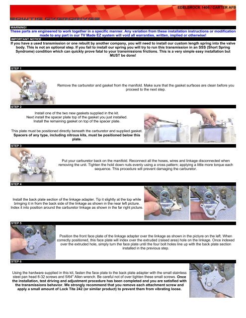
Remove the carburetor and gasket from the manifold. Make sure that the gasket surfaces are clean before you<br />
proceed to the next step.<br />
Install one of the two new gaskets supplied in the kit.<br />
Next install the spacer plate top of the gasket you just installed.<br />
Install the remaining gasket on top of the spacer plate.<br />
This plate must be positioned directly beneath the carburetor and supplied gasket.<br />
Spacers of any type, including nitrous kits, must be positioned below this<br />
plate.<br />
STEP 3<br />
STEP 4<br />
Put your carburetor back on the manifold. Reconnect all the hoses, wires and linkage disconnected when<br />
removing the unit. Tighten the hold down nuts evenly using a cross pattern; applying a little more torque each<br />
sequence. This procedure will prevent damaging the carburetor.<br />
Install the back plate section of the linkage adapter. Tip it slightly at the top while<br />
bringing it in from the back side of the linkage as shown in the near left picture.<br />
Index it into position around the carburetor linkage as shown in the far right picture.<br />
STEP 5<br />
STEP 6<br />
Position the front face plate of the linkage adapter over the linkage as shown in the picture on the left. When<br />
correctly positioned, this face plate will index over the extruded (raised area) hole on the linkage. Once indexed<br />
over the extruded hole, simply turn the face plate until the four bolt holes line up with the back plate section<br />
installed in the previous step.<br />
Using the hardware supplied in this kit, fasten the face plate to the back plate adapter with the small stainless<br />
steel pan head 6-32 screws and 5/64" Allen wrench. Be careful not of over tighten these small screws. Once<br />
the installation, test driving and adjustment procedure has been completed and you are satisfied with<br />
the transmissions behavior. We strongly recommend that you remove each attachment screw and<br />
apply a small amount of Lock Tite 242 (or similar product) to prevent them from vibrating loose.
STEP 7<br />
SETTING UP YOUR TV CABLE<br />
Refer to the TV cable installation instructions<br />
Align the roll pins on the back side of the cam into the slots on the linkage adapter<br />
face plate. Once the cam is indexed correctly, install the 8/32" cap screw and<br />
tighten using the provided 9/64" Allen wrench. Again be careful not to over tighten<br />
this small screw.<br />
PRESSURE TEST<br />
Congratulations, you now have the mounting plate, linkage adapter, cam and have the TV cable installed.<br />
If you purchased one of our transmissions, our warranty requires a correct TV set up, pressure verification and correct operation be<br />
demonstrated during a test drive. Click on the pressure gauge installation guide link below, hook the pressure gauge up to your transmission.<br />
Then: click on the pressure test procedures below, take your pressure readings and call us. Once proper operating pressures and responses<br />
are verified, you will be ready for your test drive! Our written test driving procedure (click below) will walk you through a step by step process<br />
which is designed to confirm that all transmissions functions are working correctly. During the test drive you will should confirm that your new<br />
transmission is operating at the proper temperature. Also during the test driving procedure you are encouraged to try the various cam<br />
positions. This system allows you to fine tune the light and medium throttle driving characteristics. Once you find the best position for your<br />
vehicle combination, you should remove each screw and put a spot of 242 Lock-Tite on the threads to prevent them from coming<br />
loose over time. Enjoy!<br />
If you purchased one of our TV Made EZ systems but don't have one of our transmissions, you are welcome to call us anyway. We would be<br />
happy to walk you through our set up, pressure testing and test driving procedures.<br />
760-947-5240 Ask for our technical service department.
700R4 STEP 1<br />
700R4 STEP 2<br />
TV SPRING INSTALLATION<br />
700R4 INSTRUCTIONS<br />
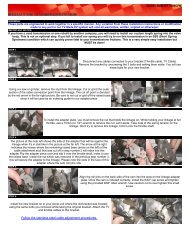
With the pan removed, locate the TV lever and bracket assembly held to the valve body assembly by the two<br />
bolts. Disconnect the TV cable at the carburetor / fuel injection linkage. Remove the two bolts(circled in red)<br />
holding the TV Lever arm and bracket assembly onto the valve body. The TV lever and bracket assembly is<br />
indexed over the roll pin.<br />
Remove the roll pin(red arrow)using a pair pliers. Try to not damage the roll pin or<br />
lose it as you will be putting it back in once you are finished.<br />
700R4 STEP 3<br />
700R4 STEP 4<br />
You will then need to remove the TV Plunger and the bushing. To do this, simply<br />
pull the TV plunger and bushing out. Now remove the old spring. If the TV plunger<br />
and bushing prove difficult, you can make the TV plunger act as a slide hammer<br />
by simply pushing it all the way in, release it in such a way as to cause it to "snap"<br />
back out, repeat this action as necessary until you get it removed.<br />
Slide the new spring that came in your kit, in place of the old one. Replace the TV Plunger and the bushing as<br />
they were before. Insert the roll pin, making sure the roll pin lines up with the "slot keyway". Replace the TV<br />
lever and bracket assembly. Fill with fluid.<br />
2004R STEP 1<br />
2004R STEP 2<br />
2004R INSTRUCTIONS<br />
With the pan removed, locate the TV lever and bracket assembly held to the valve body assembly by the two<br />
bolts. Disconnect the TV cable at the carburetor / fuel injection linkage. Remove the two bolts(circled in red)<br />
holding the TV Lever arm and bracket assembly onto the valve body. The TV lever and bracket assembly is<br />
indexed over the roll pin.<br />
Remove the roll pin(red arrow)using a pair pliers. Try to not damage the roll pin or<br />
lose it as you will be putting it back in once you are finished.<br />
2004R STEP 3<br />
2004R STEP 4<br />
You will then need to remove the TV Plunger and the bushing. To do this, simply pull the TV plunger and<br />
bushing out. Now remove the old spring. If the TV plunger and bushing prove difficult, you can make the TV<br />
plunger act as a slide hammer by simply pushing it all the way in, release it in such a way as to cause it to<br />
"snap" back out, repeat this action as necessary until you get it removed.<br />
Slide the new spring that came in your kit, in place of the old one. Replace the TV Plunger and the bushing as<br />
they were before. Insert the roll pin, making sure the roll pin lines up with the "slot keyway". Replace the TV<br />
lever and bracket assembly. Fill with fluid.
CHECKING THE TV VALVE ASSEMBLY<br />
CALIBRATION PROCEDURE<br />
Time, heat and continuous use, will invariably cause the components of the transmissions' Throttle Valve system (part throttle valve, spring<br />
and throttle valve) to loose their precise calibration relationship. Bow Tie <strong>Overdrives</strong> TV Made EZ system is engineered to work with a<br />
properly calibrated part throttle, spring and TV valve assembly. Our TV Made EZ system cannot fix programming issues associated with<br />
an incorrectly calibrated TV system. In fact, if left out of calibration, our system can sometimes exaggerate these issues. Fixing a TV<br />
valve system that's out of calibration is quite simple, quick and easy. We have always relied on Transgo's Patented TV correction<br />
system. We have tried many systems offered by other companies and the Transgo kit is the most foolproof. We use, highly<br />
recommend and offer for sale, their TV correction kit for $27.00 and have them in stock for immediate shipment.<br />
NOTES<br />
The TV system directly and indirectly controls or influences just about everything that occurs during the operation of a Th-700R4 or Th-<br />
2004R. Everything the transmission needs to know about pressure control plus all aspects of the transmissions behavior must be<br />
signaled to these transmissions through the TV cable system. To enjoy the incredible benefits of these modern overdrive<br />
automatics, we Hot Rodders no longer have the crudely simple but very effective "no brainer" vacuum modulator signal to protect<br />
and control the transmission like used in the ever popular Th-350 and Th-400 transmissions. No more plug and play!<br />
The following is a quick overview of the things directly controlled or influenced by the TV Cable system.<br />
Hydraulic pump volume output, pressure boost and regulation (critical to friction life)<br />
Upshift timing and feel in relationship to throttle position (critical to your enjoyment)<br />
Part throttle down shifts (when it happens relative to accelerator pedal position))<br />
Full throttle detent down shifts (when and how many gears)<br />
Shift firmness, timing and feel (critical to overall enjoyment)<br />
While all these items are important for proper transmission operation, sufficient hydraulic pump output and adequate fluid pressure<br />
during all operating situations is critical to survivability and longevity. Even the most expensive, highest quality frictions (bands and<br />
clutches) will eventually fail if allowed to slip excessively. Any increase in torque output by your engine must be instantly offset by at least<br />
an offsetting amount of hydraulic clamping force applied to these bands and clutches. Failure to do so and these frictions can fail<br />
very quickly indeed!<br />
On the other hand, incorrect transmission behavior normally has little to do with a transmissions longevity but has everything to do with<br />
whether you'll enjoy driving your vehicle. A transmission that will not downshift at all or downshifts too soon, upshifts too early or too late,<br />
too hard or too soft relative to a particular throttle setting, can be very frustrating! After spending the incredible amount of time, money and<br />
effort it requires to build a modern Hot Rod only to have the transmission behave improperly can be very discouraging to say the least. Our<br />
TV Made EZ system and this white paper were created to help Hot Rod builders establish a TV cable relationship that always protects the<br />
internal workings with adequate hydraulic pressure and volume. What makes our system unique is its ability to provide the means for<br />
adjusting the behavior of these wonderful overdrive transmissions.<br />
Before you even begin to set up the TV system on a custom installation, always insure that the accelerator pedal inside of the cab will cause<br />
the carburetor or fuel injection to go to it wide open throttle position. Many installers assume this is taking place when in fact well over 60% of<br />
all the cars and trucks that come into our shop will not get wide open throttle with the accelerator pedal! If you perform the installation and set<br />
up of our TV Made EZ system correctly, but you fail to get wide open throttle, you've pretty much wasted your time since the transmission will<br />
still not behave correctly! Before you start we strongly suggest you get someone to step on the accelerator pedal while you confirm your<br />
system is reaching wide open throttle at the carburetor or fuel injection. If you are replacing an older style transmission that used a vacuum<br />
modulator system, the installation of a TV system, required by the Th-700R4 and Th-2004R transmissions will add extra load to the<br />
accelerator system. You should check this again once you have it installed and set up properly.<br />
The Th-700R4/Th-2004R signaling process starts at the vehicles accelerator pedal, is relayed through the carburetor/fuel injection linkage<br />
down the TV cable where it controls the pivoting lever in the pictures below. As the TV cable is pulled by the carburetor/fuel injection linkage,<br />
the pivoting lever pushes inward on the Part Throttle/Detent Valve (picture #1 below). The Part Throttle/Detent valve pushes on the coil<br />
spring which in turn relays this movement to the Throttle Valve (see the pictures above). Starting at the accelerator pedal, the Throttle<br />
Valve is the last component in this system to receive its signal, at the same time it's the only component that'sabsolutely critical to the<br />
transmissions longevity. The TV valve is critical to transmission longevity because it's the component that directly controls the<br />
output of the transmissions internal hydraulic pump! Calibrating this system so any movement of the accelerator pedal provides<br />
instant hydraulic pressure response signaled by the Throttle Valve is now obvious! Pushing the accelerator pedal will cause the<br />
engine to instantly produce more torque which must be offset by increasing the hydraulic pressure applied to the frictions to<br />
prevent slippage. The TV cable is the only link from the throttle valve to the outside world; its importance is immediately apparent!<br />
Since the TV valve is the last component in this system, the need for a properly calibrated TV system is also obvious!<br />
The Part Throttle Detent Valve is the first of three components placed in series down a common bore in the valve body (see picture above)<br />
and is the only one of these components visible when the pan is removed. The next component is a coil spring followed by the "Throttle<br />
Valve". Any inward movement by the Part Throttle Detent Valve is relayed mechanically by the coil spring to the Throttle Valve.
STEP 1<br />
With the transmission pan removed and the TV cable disconnected from your carburetor or fuel injection system, locate the part<br />
throttle/detent on the valve body (picture number 1). We have painted the rings orange on this Th-700R4 part throttle detent valve and the<br />
aluminum bushing it rides in. This was done for clarity. Picture #1 shows a correctly homed valve. Picture number two shows an incorrectly<br />
homed valve. Original General Motors TV system plungers will not totally return to their "home" position as shown in picture #1 because<br />
stock systems didn't provide a return spring to mechanically "home" this TV valve assembly. In the original system, the TV valve was<br />
designed to home hydraulically once the engine was started. The transmissions hydraulic pump rotor is directly driven by the drive hub of the<br />
torque converter. This drive hub engages the inside rotor drive tangs when its installed into the transmission. The torque converter is bolted<br />
to the flexplate in turn bolted to the crankshaft. Consequently, transmissions hydraulic pump rotor turns at engine speed and starts pumping<br />
the moment the engine is started.<br />
Whether your TV system is totally stock or in a transmission that been rebuilt check the TV system using the following method: Push the<br />
plunger all the way in until it's even with the face of the aluminum bushing it rides in. Slowly release the plunger. Once it stops moving, check<br />
to see that it's all the way out. Try to pull the plunger out further; if it comes out further, install a TV correction kit. This should be done<br />
regardless of the cause, whether the TV system spring became too short over time or it's just not homing because there's no factory return<br />
spring to push this assembly home. At this point, the cause really makes no difference, since you must now remove the valve body to correct<br />
the problem either way, it's just smart money to install a TV correction system into the valve body while it's off. Once the TV correction<br />
system is installed, in the future you will be able to quickly verify whether this system has remained in proper calibration without pulling the<br />
pan. This is done by simply hooking up a 0-300 PSI gauge to the pump pressure port and following the pressure test procedure.<br />
The pictures above show the part throttle detent plunger in a Th-700R4. Note it has rings machined into the plungers O.D. The plunger in a<br />
Th-2004R has a smooth O.D. but the function is the same. Without a correctly calibrated TV system, you cannot expect the transmission to<br />
behave right.
700R4 TV WIRE CONNECTOR LINK LOCATION 2004R TV WIRE CONNECTOR LINK LOCATION<br />
STEP 1<br />
STEP 2<br />
We install a new TV cable seal into every transmission we build. A new seal is also<br />
provided with new TV cables. With the transmission in the vehicle, it's very difficult<br />
to see if a seal is already installed into the case. Don't try to install two seals into<br />
the same hole! The proper method for installing the TV cable is to remove the seal<br />
from the end of the TV cable, install one into the case, lube the end of the TV cable<br />
housing then slide this freshly lubricated housing into the seal in the case. Steps<br />
three and four will take you through this picture by picture.<br />
STEP 3<br />
STEP 4<br />
TV CABLE INSTALLATION<br />
The TV cable is connected to the passenger side of Th-2004R and Th-700R4<br />
transmissions at the locations shown in the above pictures. Same side as your<br />
dipstick. The picture at the far left shows the wire link and the TV cable to case<br />
seal. This seal must be placed into the transmission before installation, not onto the<br />
end of the TV cable housing! The wire link will be inserted into the hole of the<br />
connector at the transmission end of the TV cable. (See closest picture at left)<br />
Slide the bent end of the link through the attachment hole at the end of the TV<br />
cable. Gently pull on the opposite end of the TV cable (carburetor/fuel injection end)<br />
of the TV cable while feeding the transmission end of the cable housing down into<br />
the transmission seal. Be sure the wire link doesn't slip out while performing this<br />
procedure.<br />
Start the end of the cable housing into the rubber seal and push it all the way in using a twisting motion until it's<br />
completely seated flush with the case. Now line up the bolt hole on the cable housing with the bolt hole on the<br />
transmission case. Install and tighten the bolt. Use caution not to over tighten and break the housing.
STEP 1<br />
STEP 2<br />
STOCK TV CABLE SETUP<br />
Insert the TV cable into the base plate bracket until you hear it click into position. To<br />
do this, match the index guide on the TV cable housing, with the notch in the base<br />
plate bracket (red circles in pictures at left). The TV cable will not go in any other<br />
way.<br />
Check that the two retaining "tabs" on the TV cable housing have spread out and locked the cable into the<br />
base plate bracket. <strong>These</strong> tabs prevent the cable housing from coming out. (Red circles at right)<br />
STEP 3<br />
STEP 4<br />
Note: The TV Made EZ system shown in the pictures at right is our system for the<br />
Edelbrock Pro-Flo 3500 , the cam on your system may not look like this, but all TV<br />
Made EZ Evolution Two systems have a similar type cable ball attachment hole in<br />
the cam.<br />
The pictures at right illustrate how to connect the TV cable by inserting the ball<br />
through the provided opening on the cam. Rotating the cable to the rear will<br />
prevent it from coming out.<br />
Pressing in and holding the 'D' shaped slider release button (pictures at left<br />
and above) the inner cable housing (known as the "slider") will be released and<br />
freely slide back and forth in a range of approximately one inch. Press the "D"<br />
button and pull the "slider" all the way to its outermost (forward towards the<br />
front of the engine) position. Positioning the slider all the way out like this<br />
makes the next step, installing of the TV cable "ball" into the hole on the TV<br />
Made EZ cam, much easier to accomplish.<br />
Once connected, press in the "D" shaped release button, push the "slider" rearward (towards the transmission) as far as it will travel. While<br />
holding the "slider" rearward, release the "D" shaped button to "fix" the slider in this rearward most position. From the drivers seat position,<br />
press the accelerator pedal all the way to the floor. While holding the accelerator pedal to the floor, have your assistant try to rotate the<br />
carburetor/fuel injection linkage further to confirm it's getting W.O.T with the accelerator pedal. If he can rotate the Throttle linkage further,<br />
you need to fix the throttle linkage. Once the pressure gauge is connected to the transmissions diagnostic port (See gauge installation<br />
instruction link below), check for instantaneous pressure rise by gently pulling the cable where it leaves the cable housing. Once instant<br />
pressure rise is confirmed, You're ready to perform your test drive!<br />
STEP 5<br />
We strongly recommend you leave the pressure gauge hooked up during<br />
all test driving. It is very educational to observe the operating pressure<br />
reactions caused by the TV system. During the test driving we also<br />
recommend taking along the Allen wrench supplied in the TV Made EZ kit that<br />
fits the cap screw that holds the cam from moving. (Like the one shown within<br />
the red circles at left) We recommend you start with the cam in the lower<br />
position (far left picture),<br />
Perform a test drive while making mental notes of the shift timing and feel characteristics during light to medium throttle driving. Stop,<br />
loosen the attachment bolt, rotate the cam clock wise to the upper position (near left picture), then perform another test drive and notice the<br />
difference in shift timing and feel during light to medium throttle driving with this different set up. We encourage you to freely experiment<br />
with the unlimited number of positions along the cam track until you find the one that gives you the best overall driving characteristics that<br />
match your driving style. Be sure to check for instantaneous pressure response with even slight cable movement after each adjustment.<br />
<strong>These</strong> adjustments can be done while the engine is running.
STEP 1<br />
BRAIDED TV CABLE SETUP<br />
Install the stainless steel braided cable adapter piece provided in the TV Made EZ kit. This adapter must be mounted on the back side of the<br />
base plate bracket as shown in the pictures above. Secure the adapter to the base plate bracket with the provided 6-32 stainless steel pan<br />
head screws and Allen wrench.<br />
STEP 2<br />
Remove the first adjuster nut, the one indicated by the red arrow in the above left picture. Position the second adjuster nut on the threaded<br />
cable housing so the adapter plate will be in the middle of the threaded areas once it's installed into the adapter plate. Slide the cable<br />
adjuster housing through the hole in the adapter plate as shown in the pictures at upper right and below left.<br />
STEP 3<br />
Screw the first adjuster nut back onto the cable adjuster housing. You're now able<br />
to make the proper starting set up of the TV system by screwing these nuts along<br />
the threaded area of the cable adjuster housing. Moving the position of these two<br />
adjuster nuts along the threaded area of the cable adjuster housing relative to the<br />
adapter plate will allow you to "preload" a slight pressure boost. Attach the pressure<br />
gauge and hose assembly. Refer to Section 4 for pressure gauge installation.<br />
With the transmission full of fluid, engine at idle, TV cable connected to the cam, preset the idle pressure so there's a minimum of two pounds<br />
of pressure higher than the disconnected TV cable reading at idle as shown in step 4.<br />
STEP 4<br />
Note: Edelbrock Pro-Flo 3500 shown in pictures, the cam on your system may<br />
not look like this, but all TV Made EZ Evolution Two systems have this hole in<br />
the cam.<br />
The pictures at right illustrate how to connect the TV cable by inserting the ball<br />
into the provided opening on the cam. Once connected, using the adjuster nuts,<br />
you need to adjust the cable until you see a 2-4 PSI increase on your pressure<br />
gauge above the pressure shown at idle with the TV cable disconnected.<br />
Once this preload pressure has been established, even slight gentle forward movement of the TV cable where it exits the TV cable adapter<br />
housing should result in instant pressure response on the gauge. This test must be done by gently pulling the TV cable not movement of the<br />
Throttle linkage! The pressure response must be evident with even very small forward movements by the TV cable. If you have one of our<br />
transmissions, refer to Section 5 for pressure test procedures. Perform the pressure test and call us.<br />
STEP 5<br />
You are ready to perform your test drive! We recommend the pressure<br />
gauge remain hooked up during all test driving. Pay attention to the reactions<br />
caused by the TV system, it is very educational. During the test driving we also<br />
recommend Allen wrench supplied in the TV Made EZ kit that fits the cap screw<br />
shown within the red circles at left. Start with the cam in the lower position (far left<br />
picture), perform a test drive while making mental notes of the shift timing and feel<br />
characteristics.<br />
Stop, loosen the attachment bolt, rotate the cam clock wise to the upper position (near left picture), then perform another test drive and notice<br />
the difference in shift timing and feel with this set up. You are free to move this cam anywhere along its engineered path with full confidence<br />
as long as you check for instantaneous pressure rise with even slight cable movements.<br />
PRESSURE TEST<br />
Now that you have your TV Made Ez kit installed, you will need to perform a standard pressure test before you do a test drive. Once you<br />
have done the pressure test, you will need to call in your pressures to verify the set up is correct. If you do not have our transmission, we still<br />
encourage you to proceed to the pressure and drive testing so we can teach you what your pressure readings mean and verify that<br />
everything is in working order, or diagnose any problems that you may have.<br />
If you have one of our transmissions, you need to to the pressure tests and call these figures in before you proceed with the test driving.
PRESSURE GAUGE INSTALLATION<br />
700R4 PRESSURE PORT LOCATION 2004R PRESSURE PORT LOCATION 4L80E PRESSURE PORT LOCATION<br />
STEP 1<br />
STEP 2<br />
Install the 1/8" NPT 90 degree elbow fitting into the transmission. As you tighten the<br />
fitting, be sure to end up with the elbow fitting pointing toward the rear of the<br />
transmission. This will ensure that the pressure gauge hose will not interfere with<br />
your shift linkage while you are test driving.<br />
STEP 3<br />
IMPORTANT NOTES<br />
The pressure gauge must be connected to the transmission at the location shown<br />
above. This is a direct fluid passage to the transmissions internal hydraulic pump.<br />
This installation will be done while the engine not running. Testing will be done<br />
with the engine running. To hook up the gauge, locate the 1/8" plug on the "Driver<br />
Side" of the transmissions bell housing as shown in the above pictures; unscrew<br />
the plug from the transmission.<br />
Screw the pressure gauge hose into the 90 degree fitting. Be sure that it's snug<br />
inside of the fitting to prevent leaking. Route the pressure gauge hose above the<br />
frame and away from the exhaust. You can now use the gauge under the hood or<br />
while test driving, routing up through the driver side window.. That's it! We don't<br />
recommend this gauge be installed permanently, it should be removed after the set<br />
up and test driving are completed.<br />
Use of a pressure gauge is the only way to be sure the TV cable system is working correctly. Refer to the<br />
pressure check procedure section for a step by step method of setting up this critical system! Adequate<br />
pressures during all transmission operations is critical to friction longevity and <strong>parts</strong> longevity. We highly<br />
recommend this procedure be followed anytime the TV cable is disconnected or it's relationship to the<br />
transmission is altered in any way. While this system is critical to the very survival of the transmission, making<br />
sure its correctly set up is not difficult to accomplish.
PRESSURE TEST SHEET<br />
PRESSURE GAUGE INSTALLATION<br />
You will need to install a 0-300psi pressure gauge in order to perform this test. The pressure gauge must be attached to the direct pump<br />
pressure port on the driver's side of the transmission. <strong>These</strong> readings should be taken right after the initial startup of the transmission, the<br />
vehicle shouldn't be driven until you verify these pressures with our facility. If the vehicle is driven prior to our approval it may void your<br />
warranty.<br />
See Pressure gauge installation guide<br />
PRESSURE TEST<br />
Please read the following three tests very carefully, these are very critical.<br />
Once you have set up the T.V. cable correctly according to the instructions for your specific T.V. system, you will need to bring the engine up<br />
to operating temperature and perform the following three tests as follows:<br />
PRESSURE @ IDLE T.V. CONNECTED<br />
With the vehicle running at an idle, make sure that the T.V. cable connected to the carburetor/fuel injection linkage, and adjusted to the<br />
appropriate settings. With the gear selector in park record the reading off of the pressure gauge. Next pull the gear selector down into reverse<br />
and take that reading, then continue to shift the shifter down through the rest of the gears one by one taking a reading in each gear.<br />
PRESSURE @ IDLE T.V. DISCONNECTED<br />
Once again with the vehicle running at a idle, disconnect the T.V. cable from the carburetor/fuel injection linkage, and simply record the<br />
pressure readings again in each gear.<br />
PRESSURE @ HIGH IDLE FULL T.V.<br />
You will need a helper to help you perform this last test. This test is a little bit more complex and will require the use of an assistant.<br />
On this test we will once again start off in park, bring the vehicle up to approximately 1500 rpm's and have your assistant pull the T.V. cable<br />
all of the way out until he can feel it stop, it will stop when it buries the plunger in the transmission, now take a pressure reading, release the<br />
T.V. cable and let the engine rpm back down to a idle. Now we need to perform this same test in the remaining six gears, upon doing this in<br />
the other gears the car is going to try to move as if we were power braking it, so we highly recommend that you set the emergency brake and<br />
keep you foot planted firmly in the brake pedal<br />
Pressure test chart<br />
Gear selector position Pressure @ idle TV Connected Pressure @ idle TV Disconnected Pressure @ high idle full TV<br />
Park<br />
Reverse<br />
Neutral<br />
Overdrive<br />
Third<br />
Second<br />
First
TEST DRIVE PROCEDURES<br />
NOTICE<br />
CAUTION MUST BE EXERCISED DURING THE INITIAL TEST DRIVE. IF YOU FEEL SOMETHING IS NOT CORRECT, STOP AND CALL<br />
US. WE CAN CORRECT WHATEVER THE PROBLEM IS BEFORE ANY DAMAGE IS DONE.<br />
DURING ALL THE YEARS OF TEST- DRIVING VEHICLES WE HAVE NEVER DAMAGED A TRANSMISSION DURING THIS PROCESS.<br />
IF SOMETHING DOESN'T FEEL RIGHT, STOP THE TEST AND CALL US TO HELP YOU DETERMINE WHAT IS WRONG.<br />
TEST DRIVE PROCEDURES<br />
It has been our experience the first hour after start up of a newly built automatic transmission is critical. Realize what we are doing is very<br />
similar to starting a new engine. Get through this phase and you are well on your way to a long happy life with your new transmission.<br />
1. When you are ready to test drive place the selector in the overdrive position. Softly run the transmission through all the forward gears.<br />
Come back to a stop and do the same thing at least two more times. This will bring the transmission up to operating temperature. Bring the<br />
vehicle back to a full stop.<br />
2. Keep the selector in the overdrive position and perform a minimum throttle first to second shift. This will be the slowest vehicle speed you<br />
can get the vehicle to ease into second gear. When the transmission shifts to second you need to aggressively floor the accelerator to make<br />
the transmission perform a second gear to first gear downshift. If the transmission fails to downshift. Terminate the test drive. Carefully return<br />
to your shop and call us.<br />
3. Next you perform a minimum throttle (Minimum vehicle speed) third gear into fourth gear. If you have a tachometer this is easy to see<br />
when this occurs. Without a tachometer you might have to play with the gear selector to determine when you are in fourth gear at minimum<br />
vehicle speed. When you are certain that you have the vehicle into forth gear at the slowest vehicle speed, aggressively floor the throttle to<br />
force the transmission to downshift to second, bypassing third in the process. If the transmission fails to perform this test, terminate the test<br />
drive and call us.<br />
4. Let the transmission go back into fourth and check for converter lock up. Put your vehicle in light acceleration with your throttle pedal. Hold<br />
that position with your right foot while you gently apply the brake pedal with your left foot. Not enough to apply the brakes but just enough to<br />
turn on the brake lights. If your brake pedal disconnect circuit is working; you will feel the engine rpm jump up as the torque converter<br />
disengages. Continue to hold the throttle position with your right foot. When you release the brake pedal with your left foot, the engines' rpm<br />
should drop right back down as the converter re-engages. You must have some acceleration going on while you perform this test or you<br />
probably won't feel the engagement and disengagement when it occurs. Now bring the vehicle back to a complete stop.<br />
5. Select manual first gear. Accelerate to 3000 rpm and hold that setting for five seconds. When you are sure the transmission will not go into<br />
second gear on its own, release the throttle pedal back to idle. You should feel a strong compression braking action happening. Accelerate<br />
back to 3000 rpm.<br />
6. Select second gear with the selector. You should get a clean crisp shift into second gear. Accelerate up to 3000 rpm and hold that rpm<br />
setting for five seconds. When you are sure the transmission won't shift on it's own into third gear, release the throttle pedal back to the idle<br />
position and check for engine compression braking once again. Accelerate back up to 3000 rpm.<br />
7. Select manual third gear with the selector. The transmission should cleanly and quickly shift into third gear. Take the engine rpm up to<br />
3000, hold it there for five seconds, release the throttle pedal and confirm that you have the correct engine compression braking. Bring the<br />
vehicle back to a complete stop.<br />
8. Perform a minimum throttle first to second gear up shift, then aggressively floor the accelerator pedal to perform a second gear to first gear<br />
downshift. This time hold the throttle pedal to the floor and record the rpm that the transmission automatically up shifts to second gear and<br />
then to third gear. If you don't have a tachometer, the shift points should feel reasonably close to appropriate for passing situations.<br />
(Note: You will be asked what your transmission and engine temperatures were at this point)<br />
9. Stop the vehicle and open the hood. Feel the return line from your cooling system. Please use some common sense here. Use extreme<br />
caution around any moving or hot engine components. Please don't call us complaining of burnt fingers or shredded clothes. When you touch<br />
the return line, do so with caution, use a quick, light tap to determine if the line is scolding hot. You should be able to touch this line without<br />
burning your hands. Even the outgoing line shouldn't be hot enough to burn you if you touch it momentarily. If you feel very high<br />
temperatures on the return line you should add a cooler. A transmission temperature gauge will help determine what is occurring. If you error<br />
on this topic, please do with too much cooling. The temperature gauge is recommended even if you don't plan to tow. 150 degrees F or less<br />
should be indicated with a temperature probe (sender) positioned in the pan. The fluid can be seriously overheated if pan temperatures<br />
exceed 150 degrees F. This happens because overheating is occurring in the converter, not the pan. What they don't realize is the<br />
temperature that we are observing is the fluid temperature after it has returned from the cooling system! People are confused about this<br />
because they know that Dextron III can withstand higher operating temperatures than 150 degrees F. What they are failing to realize is the<br />
gauge is reading the fluid after it has gone through the cooling system. While it is impractical to probe the inside of the torque converter when<br />
it is operating, it's known to be the hottest component in the system. The converter is the heat source and the main reason a cooling system<br />
is essential to automatic transmissions. So we have learned though years of observation this transmission is doing fine at 150 degrees F and<br />
overheating when over that if you are sensing the fluid temperature in the pan.<br />
Call with your observations concerning this drive test. Install the remaining pan bolts. (See torque specification sheet) Check for any leaks.<br />
<strong>These</strong> transmissions normally are not "Leakers", but the cooling lines can sometimes be pesky especially at the transmission end. The lines<br />
can be difficult to get a wrench on correctly. Recheck the fluid level.