Link-Belt HTC-8670 - 70-ton - Bigge Crane and Rigging Co.
Link-Belt HTC-8670 - 70-ton - Bigge Crane and Rigging Co.
Link-Belt HTC-8670 - 70-ton - Bigge Crane and Rigging Co.

You also want an ePaper? Increase the reach of your titles
YUMPU automatically turns print PDFs into web optimized ePapers that Google loves.
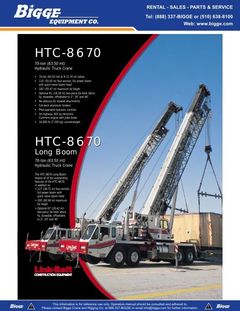
<strong>HTC</strong>-<strong>86<strong>70</strong></strong><br />
<strong>70</strong>-<strong>ton</strong> (63.50 mt)<br />
Hydraulic Truck <strong>Crane</strong><br />
<strong>70</strong>-<strong>ton</strong> (63.50 mt) at 9' (2.74 m) radius<br />
115' (35.05 m) four-section, full power boom<br />
with quick-reeve boom head<br />
182' (55.47 m) maximum tip height<br />
Optional 61' (18.59 m) two-piece (bi-fold) lattice<br />
fly, stowable, offsettable to 2°, 20° <strong>and</strong> 40°<br />
No deducts for stowed attachments<br />
Full-deck aluminum fenders<br />
Pilot-operated hydraulic controls<br />
On-highway 365 hp electronic<br />
Cummins engine with Jake brake<br />
16,000 lb (7 258 kg) counterweight<br />
<strong>HTC</strong>-<strong>86<strong>70</strong></strong><br />
Long Boom<br />
<strong>70</strong>-<strong>ton</strong> (63.50 mt)<br />
Hydraulic Truck <strong>Crane</strong><br />
The <strong>HTC</strong>-<strong>86<strong>70</strong></strong> Long Boom<br />
boasts all of the outst<strong>and</strong>ing<br />
features of the <strong>HTC</strong>-<strong>86<strong>70</strong></strong>,<br />
in addition to:<br />
127' (38.71 m) four-section,<br />
full power boom with<br />
quick reeve boom head<br />
200' (60.96 m) maximum<br />
tip height<br />
Optional 67' (20.42 m)<br />
two-piece (bi-fold) lattice<br />
fly, stowable, offsettable<br />
to 2°, 20° <strong>and</strong> 40°
<strong>HTC</strong>-<strong>86<strong>70</strong></strong><br />
World class combination of form <strong>and</strong><br />
function ... only from <strong>Link</strong>-<strong>Belt</strong>!<br />
• A-max boom mode<br />
<strong>Co</strong>nfined Area Lifting Capacities (CALC)<br />
BOSS boom<br />
Ultra-Cab with CabWalk<br />
<strong>HTC</strong>-<strong>86<strong>70</strong></strong><br />
Long Boom<br />
All the great features of the<br />
<strong>HTC</strong>-<strong>86<strong>70</strong></strong> PLUS:<br />
Longer boom<br />
Longer fly<br />
4-section full power<br />
boom with attachment flexibility<br />
• <strong>HTC</strong>-<strong>86<strong>70</strong></strong>:<br />
- 38' to 115' (11.58 - 35.05 m)<br />
- Maximum tip height is 182' (55.47 m) with the attachment <strong>and</strong> main<br />
boom used in combination<br />
• <strong>HTC</strong>-<strong>86<strong>70</strong></strong> LB:<br />
- 41' to 127' (12.50 - 38.71 m)<br />
- Maximum tip height is 200' (60.96 m) with the attachment <strong>and</strong> main<br />
boom used in combination<br />
Features the “Boss,” <strong>Link</strong>-<strong>Belt</strong>’s patented boom design of<br />
high-strength angle cords <strong>and</strong> high formability sidewall embossments<br />
A-max mode<br />
The basic boom extension (mode “B”) self-proportions all four sections<br />
equally. The exclusive A-max mode (mode “A”) extends only the inner<br />
mid-section to 63' 6" (19.39 m) on the <strong>HTC</strong>-<strong>86<strong>70</strong></strong> <strong>and</strong> 69' 6" (21.21 m) on<br />
the <strong>HTC</strong>-<strong>86<strong>70</strong></strong> LB, offering substantially increased capacities for in-close,<br />
maximum capacity picks, <strong>and</strong> providing the operator the capability to<br />
match the crane’s configuration to specific job site conditions.<br />
Optional two-piece bi-fold lattice fly<br />
<strong>HTC</strong>-<strong>86<strong>70</strong></strong>: 36' 6" - 61' (11.13 - 18.59 m)<br />
<strong>HTC</strong>-<strong>86<strong>70</strong></strong> LB: 39' 6" - 67' (12.04 - 20.42 m)<br />
Erection of two-piece (bi-fold) lattice fly is a one-man operation<br />
Exclusive design reduces side deflection when lifting load<br />
Easy to erect <strong>and</strong> stow<br />
Also available: One-piece lattice fly with lugs to allow addition of<br />
second section<br />
- <strong>HTC</strong>-<strong>86<strong>70</strong></strong>: 36' 6" (11.13 m), <strong>HTC</strong>-<strong>86<strong>70</strong></strong> LB: 39' 6" (12.04 m)<br />
Attachments offset to 2°, 20° <strong>and</strong> 40°<br />
The <strong>Co</strong>nfined Area Lifting Capacities (CALC)<br />
system provides three outrigger positions:<br />
full retraction<br />
intermediate extension<br />
full extension<br />
Outrigger pins eliminate guesswork by automatically<br />
positioning outriggers at midpoint position.<br />
Sheppard rack & pinion steering system<br />
provides 40° wheel cuts. The <strong>HTC</strong>-<strong>86<strong>70</strong></strong><br />
has a 38' 10" (11.84 m) turning radius, <strong>and</strong><br />
the <strong>HTC</strong>-<strong>86<strong>70</strong></strong> LB has a 41' 7" (12.67 m)<br />
turning radius.<br />
<strong>Link</strong>-<strong>Belt</strong>’s innovative two-part paint coating technology,<br />
coupled with a pre-assembly paint process, provides the finest quality<br />
coating system available today. This enhances the overall aesthetic appeal<br />
of the final machine, as nuts, bolts, hoses <strong>and</strong> various parts are no longer<br />
painted. As a result, paint chipping, cracking <strong>and</strong> deterioration are<br />
significantly reduced when service work <strong>and</strong> disassembly are required.<br />
The paint is totally cured using an oven-baking process prior to assembly.<br />
All powder-coated hydraulic lines <strong>and</strong> electrical routings are tied off with<br />
brass clamps. Nylatron insulators are impervious to salt or chemicals.<br />
Quick reeve head machinery for fast,<br />
easy line change<br />
Hammerhead boom nose allows the<br />
operator to work at high boom angles<br />
without fouling wire rope.<br />
Deflector rollers prevent<br />
premature wire rope wear<br />
when working at low<br />
boom angles.<br />
Lightweight nylon head sheaves<br />
reduce overall machine weight <strong>and</strong><br />
increases lift capacities.<br />
Available auxiliary lifting sheave is<br />
pinned on (not bolted) <strong>and</strong> requires<br />
only one man for installation. It can<br />
be used for quick lifts with one or<br />
two parts of line when the boom<br />
head has multiple reeving. And it<br />
remains on the boom through any fly<br />
combination, regardless of offset.<br />
Lightweight fiberglass engine hood is common<br />
to all <strong>HTC</strong> cranes, <strong>and</strong> can be removed as a<br />
complete unit for heavy engine maintenance.<br />
All-aluminum wheels<br />
<strong>and</strong> front/rear radial<br />
tires are rated for use<br />
on <strong>70</strong>-<strong>ton</strong> cranes,<br />
<strong>and</strong> are interchangeable<br />
with all other cranes in<br />
the <strong>HTC</strong> series, <strong>70</strong>-<strong>ton</strong><br />
<strong>and</strong> smaller.
Pis<strong>ton</strong> motor hydraulic hoist system<br />
St<strong>and</strong>ard load hoist system consists of a main winch with two-speed motor<br />
<strong>and</strong> automatic brake for power up/down mode of operation. A bi-directional<br />
pis<strong>ton</strong>-type hydraulic motor, driven through a planetary reduction unit provides<br />
precise smooth load control with minimal rpm’s.<br />
Asynchronous, parallel double cross-over grooved drums minimize rope<br />
harmonic motion, improving spooling <strong>and</strong> increasing rope service life.<br />
A two-speed auxiliary winch is an available option.<br />
For greater productivity <strong>and</strong> control, the five pump-section hydraulic<br />
circuit provides smooth, simultaneous function of winches, boom hoist,<br />
swing <strong>and</strong> boom telescope.<br />
Non-slip<br />
surface<br />
strips on<br />
carrier deck<br />
Mechanical boom<br />
angle indicator -<br />
st<strong>and</strong>ard<br />
Aluminum fuel tank<br />
eliminates internal<br />
corrosion <strong>and</strong> is<br />
interchangeable with<br />
all <strong>HTC</strong> <strong>and</strong> RTC cranes<br />
of equal sizes.<br />
Another first from <strong>Link</strong>-<strong>Belt</strong>,<br />
the axle lift system holds the<br />
rear axles level while the<br />
crane is on outriggers.<br />
The Ultra-Cab is<br />
roomier <strong>and</strong> quieter<br />
than traditional cabs<br />
Six-way adjustable fabric seat with<br />
lift-up armrest (which deactivates<br />
control functions when raised)<br />
Armrest mounted, responsive dual axis<br />
hydraulic controllers<br />
Bubble level sight level mounted on<br />
side console<br />
Ducted air through automotive-style<br />
directional vents<br />
Sliding right side, rear windows <strong>and</strong><br />
swing-up roof window<br />
Single foot pedal control<br />
Automotive-style windshield<br />
<strong>Co</strong>rner-post-mounted, backlit gauges<br />
Large, sweeping electric wipers<br />
Dashless design<br />
Interchangeable with entire <strong>HTC</strong> <strong>and</strong><br />
RTC lines, with exception of the<br />
RTC-8030 Series II <strong>and</strong> RTC-8060<br />
Integral rated capacity limiter<br />
The Microguard 434 aids the operator in safe <strong>and</strong> efficient<br />
operation by continuously monitoring boom length, boom<br />
angle, head height, radius of load, machine configuration,<br />
allowed load, actual load <strong>and</strong> percent of allowed load.<br />
An exclusive feature on the <strong>HTC</strong>-<strong>86<strong>70</strong></strong> <strong>and</strong> <strong>HTC</strong>-<strong>86<strong>70</strong></strong> LB is the<br />
Operator Defined Area Alarm. By setting two points, the operator<br />
creates an imaginary vertical plane to maintain a safe working<br />
distance from nearby obstacles. Should the operator<br />
attempt to operate the crane beyond the plane, the RCL will<br />
sound an alarm.<br />
Full air, S-cam brakes<br />
on all wheel ends with<br />
automatic slack<br />
adjusters<br />
Two st<strong>and</strong>ard carrier-mounted outrigger controls, located on each<br />
side of the carrier, include a throttle-up switch that brings engine up<br />
to 1,200 rpm’s for fast outrigger deployment. For fine<br />
level adjusting of the carrier, throttle can be taken down<br />
to idle.<br />
Lightweight aluminum outrigger floats with “quick<br />
latch” feature improves set-up time.<br />
The Microguard 434 also features:<br />
Improved access time<br />
Radio frequency shielding<br />
Large liquid crystal alpha-numeric display<br />
Total system override capabilities to provide for rigging<br />
requirements<br />
Optional graphic display bar, positioned near the top of the<br />
windshield for optimum viewing during crane operation<br />
alerts the operator of the current lift capacity through a<br />
series of green, yellow <strong>and</strong> red lights.<br />
Superior accessibility<br />
Access to the operator’s cab <strong>and</strong> engine<br />
compartment is superb with strategicallylocated<br />
ladders <strong>and</strong> steps. The pull-out<br />
CabWalk slides out from its secured<br />
travel position underneath the operator’s<br />
cab to give the operator a platform to<br />
st<strong>and</strong> on for easy entry <strong>and</strong> exit from<br />
the cab.<br />
Smooth ride with<br />
air-ride suspension<br />
St<strong>and</strong>ard air-ride suspension provides a<br />
smooth ride <strong>and</strong> precise h<strong>and</strong>ling. For<br />
"pick-<strong>and</strong>-carry" operations, the air bags<br />
are deflated, allowing the suspension to<br />
rest solid on the carrier frame. When the<br />
"pick-<strong>and</strong>-carry" operation is completed,<br />
simply flip a switch <strong>and</strong> the air bags<br />
automatically re-inflate.
Serviceability<br />
Wide opening engine doors<br />
provide excellent accessibility,<br />
fittings are staggered for<br />
easy servicing, <strong>and</strong> st<strong>and</strong>ard<br />
quick disconnects installed<br />
at various locations in the<br />
hydraulic system allow the<br />
hydraulic pressure to be<br />
quickly <strong>and</strong> easily checked<br />
with <strong>Link</strong>-<strong>Belt</strong>’s exclusive<br />
diagnostic kit (optional).<br />
The driver can use the stop engine <strong>and</strong> check engine indicator lights to troubleshoot the<br />
engine. An engine diagnostic connector, located under the carrier cab dash, allows an<br />
engine service technician to further analyze engine problems with an engine diagnostic<br />
data reader.<br />
Transportability<br />
The <strong>HTC</strong>-<strong>86<strong>70</strong></strong> <strong>and</strong> <strong>HTC</strong>-<strong>86<strong>70</strong></strong> LB come st<strong>and</strong>ard with 12,000 lbs of counterweight <strong>and</strong><br />
can also use two auxiliary 2,000 lb counterweights. The hydraulic counterweight<br />
removal system can position 12,000 lbs of counterweights on the carrier deck for<br />
transport.<br />
Stowable attachments<br />
Swing-away lattice flys are easily stored for transport or can be removed to meet<br />
specific road laws.<br />
Cruise to your next job site<br />
Utilizing a Detroit Diesel Series 60 engine <strong>and</strong> an Ea<strong>ton</strong><br />
transmission, the <strong>HTC</strong>-<strong>86<strong>70</strong></strong> <strong>and</strong> <strong>HTC</strong>-<strong>86<strong>70</strong></strong> LB can run up to<br />
58.20 mph (93.66 km/hr) top speed on the highway, unmatched<br />
in the industry today. Move it on the job site at less than 0.5 mph<br />
(.80 km/hr) creep speed at idle for maximum maneuverability.<br />
Detroit Diesel 365 horsepower (272 kW) engine<br />
Ea<strong>ton</strong> 11-speed forward, 3-speed reverse transmission<br />
Electronic throttle control<br />
Cruise control<br />
FOR MORE INFORMATION, CONTACT YOUR AUTHORIZED LINK-BELT DISTRIBUTOR:<br />
Carrier cab<br />
The carrier cab <strong>and</strong> engine cowling are manufactured of the same<br />
LFC 2000 construction process as the upper operator’s cab. This<br />
rust-free, laminated fibrous composite material combined with<br />
additional acoustical treatments assure the operator of maximum<br />
highway comfort. And the rack <strong>and</strong> pinion steering puts the operator<br />
in complete control. Interchangeable with entire <strong>HTC</strong> line.<br />
Additional comfort <strong>and</strong> safety features include:<br />
Dash-mounted comprehensive instrumentation with<br />
backlit gauges<br />
Sliding side <strong>and</strong> rear windows <strong>and</strong> roll up/down door window<br />
provides excellent ventilation<br />
Fully adjustable air ride fabric seat<br />
Suspended pedals<br />
Rear view mirrors<br />
Lexing<strong>ton</strong>, Kentucky<br />
www.linkbelt.com<br />
® <strong>Link</strong>-<strong>Belt</strong> is a registered trademark. <strong>Co</strong>pyright 2001. All rights<br />
reserved. We are constantly improving our products <strong>and</strong> therefore<br />
reserve the right to change designs <strong>and</strong> specifications.<br />
Litho in U.S.A. 09/01 #4262
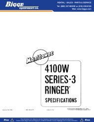
Specifications<br />
Telescopic Boom Truck <strong>Crane</strong><br />
<strong>HTC</strong>–<strong>86<strong>70</strong></strong> <strong>70</strong>–<strong>ton</strong> (63.5 metric <strong>ton</strong>s)<br />
11’ 6.88”<br />
(3.52 m)<br />
4’ 7.125” (2.97 m)<br />
13.875”<br />
(2.97 m)<br />
6’ 7.69”<br />
(2.02 m)<br />
4.5”<br />
(114 mm)<br />
5’ 1.38”<br />
(1.56 m)<br />
17<br />
8’ 6” (2.59 m)<br />
<strong>Link</strong>–<strong>Belt</strong><br />
6’ 11” (2.12 m)<br />
38’ 0”<br />
(11.58 m)<br />
<strong>Link</strong>–Be<br />
25”<br />
(0.65 m)<br />
7’ 9” (2.36 m)<br />
Full Retraction<br />
9’ 9” (2.97 m)<br />
Full Retraction<br />
14’ 7” (4.45 m) Intermediate Extension<br />
16’ 7” (5.05 m) Intermediate Extension<br />
24’ 0” (7.32 m) Full Extension<br />
26’ 0” (7.92 m) Full Extension<br />
8.125”<br />
(0.20 m)<br />
25”<br />
(0.65 m)<br />
26’ 9.5”<br />
(8.17 m)<br />
12.125”<br />
(0.31 m)<br />
45’ 7”<br />
(13.89 m)<br />
19’ 3”<br />
(5.86 m)<br />
<br />
Ground level<br />
<br />
<br />
<br />
General Dimensions feet meters<br />
Turning radius (wall to wall) 49’ 1.5” 14.97<br />
Turning radius (curb to curb) 41’ 10.5” 12.76<br />
Ground clearance 13.25” 0.34<br />
Tailswing 13’ 8.125” 4.17<br />
Litho in U.S.A. 3/03 #5382 (supersedes #5354)<br />
13.25”<br />
(0.34 m)<br />
11’ 0”<br />
(3.35 m)<br />
1’ 8” (0.50 m)<br />
with machine<br />
on outriggers<br />
<br />
<br />
27”<br />
(0.69 m)<br />
2’ 7”<br />
(0.80 m)<br />
<br />
<br />
<br />
<strong>HTC</strong>–<strong>86<strong>70</strong></strong><br />
27”<br />
(0.69 m)<br />
8’ 11”<br />
(2.72 m)<br />
9’ 11”<br />
(3.04 m)<br />
17<br />
3.5” (89 mm)<br />
<br />
5’ 6.25”<br />
(1.68 m)<br />
3’ 8.625”<br />
(1.13 m)<br />
10’ 8.88”<br />
(3.71 m)
Upper Structure<br />
Boom<br />
Patented Design<br />
Boom side plates have diamond shaped<br />
impressions for superior strength to weight<br />
ratio <strong>and</strong> 100,000 p.s.i. (689.5 MPa) steel<br />
angle chords for lateral stiffness.<br />
Boom telescope sections are supported by<br />
top, bottom <strong>and</strong> adjustable side wear<br />
shoes to prevent metal to metal contact.<br />
Boom<br />
38 – 115’ (11.58 – 35.05 m) four–section<br />
full power boom.<br />
Two mode boom extension<br />
The basic mode is the full power, synchronized<br />
mode of telescoping all sections proportionally<br />
to 115’ (35.05 m).<br />
The exclusive “A–max” mode (or mode<br />
‘A’) extends only the inner mid section to<br />
63’ 6” (19.39 m) offering increased capacities<br />
for in–close, maximum capacity picks.<br />
Boom Head<br />
Five 16–1/2” (0.42 m) root diameter nylon<br />
sheaves with a fifth nylon sheave available<br />
to h<strong>and</strong>le up to 10 parts of wire rope.<br />
Easily removable wire rope guards<br />
Rope dead end lugs provided on each side<br />
of boom head.<br />
Boom head designed for quick reeve of<br />
hook block.<br />
Fly pinning alignment tool.<br />
Boom Elevation<br />
One <strong>Link</strong>–<strong>Belt</strong> designed hydraulic cylinder<br />
with holding valve <strong>and</strong> bushing in each end.<br />
H<strong>and</strong> control for controlling boom elevation<br />
from –3° to +78°.<br />
Optional Auxiliary Lifting Sheave<br />
Single 16–1/2” (0.42 m) root diameter nylon<br />
sheave with removable wire rope<br />
guard, mounted to boom.<br />
Use with one or two parts of line off the<br />
optional front winch.<br />
Does not affect erection of fly or use of<br />
main head sheaves for multiple reeving.<br />
Optional<br />
<strong>70</strong>–<strong>ton</strong> (63.5 mt) quick reeve hook block.<br />
8–1/2 <strong>ton</strong> (7.7 mt) hook ball.<br />
Boom floodlight.<br />
Mechanical Boom Angle Indicator<br />
Fly<br />
Optional<br />
36’ 6” (11.13 m) One piece lattice fly, stowable,<br />
offsettable to 2°, 20° <strong>and</strong> 40°.<br />
Lugs to allow for second section.<br />
36’ 6” – 61’ (11.13 – 18.59 m) Two piece<br />
(bifold) lattice fly, stowable, offsettable to<br />
2°, 20° or 40°.<br />
Cab <strong>and</strong> <strong>Co</strong>ntrols<br />
Environmental Ultra–Cab<br />
Laminated fiborus composite material; isolated<br />
from sound with acoustical fabric insulation.<br />
<strong>HTC</strong>–<strong>86<strong>70</strong></strong><br />
Windows are tinted <strong>and</strong> tempered safety<br />
glass.<br />
Sliding rear <strong>and</strong> right side windows <strong>and</strong><br />
swing–up roof window for maximum visibility<br />
<strong>and</strong> ventilation.<br />
Slide–by–door opens to 3’ (0.91 m) width.<br />
Six–way adjustable seat, with seat belt, for<br />
maximum operator comfort.<br />
H<strong>and</strong>–held outrigger controls <strong>and</strong> sight<br />
level bubble located on left side of cab.<br />
Diesel cab heater<br />
Pull–out Cabwalk Circulating fan<br />
Audible swing alarm Warning horn<br />
Backup alarm Dome light<br />
Fire extinguisher Cup holder<br />
12–volt accessory outlet Sun screen<br />
Electric windshield wiper H<strong>and</strong> throttle<br />
Windshield washer Mirrors<br />
Top hatch window wiper Defroster fan<br />
Optional<br />
Amber strobe light<br />
Emergency steering system<br />
Amber rotating beacon<br />
Hydraulic heater<br />
Air conditioning<br />
<strong>Co</strong>ntrols<br />
Hydraulic controls (joystick type) for:<br />
Swing Main winch<br />
Optional auxiliary winch Boom hoist<br />
Foot controls for:<br />
Boom telescope Swing brake<br />
Engine throttle<br />
Optional<br />
Single axis controls Auxiliary winch<br />
Cab Instrumentation<br />
<strong>Co</strong>rnerpost–mounted gauges for:<br />
Hydraulic oil temperature<br />
Audio/Visual warning system<br />
Tachometer Oil pressure<br />
Voltmeter Fuel<br />
Water temperature<br />
Rated Capacity Limiter<br />
Microguard 434 Graphic audio–visual<br />
warning system built into dash with anti–<br />
two block <strong>and</strong> function limiters.<br />
Operating data available includes:<br />
Machine configuration.<br />
Boom length Boom angle<br />
Head height Radius of load<br />
Allowed load Actual load<br />
% of allowed load<br />
Presettable alarms include:<br />
Maximum <strong>and</strong> minimum boom angles.<br />
Maximum tip height.<br />
Maximum boom length.<br />
Swing left/right positions.<br />
Operator defined area alarm is st<strong>and</strong>ard.<br />
Anti–two block weight designed for quick<br />
reeve of hookblock.<br />
<br />
Optional<br />
Internal RCL light bar: Visually informs<br />
operator when crane is approaching maximum<br />
load capacity with a series of green,<br />
yellow <strong>and</strong> red lights.<br />
External RCL light bar: Visually informs<br />
ground crew when crane is approaching<br />
maximum load capacity kickouts <strong>and</strong> presettable<br />
alarms with a series of three<br />
lights; green, yellow <strong>and</strong> red.<br />
Swing<br />
Bi–directional hydraulic swing motor<br />
mounted to a planetary reducer for 360°<br />
continuous smooth swing at 1.7 r.p.m.<br />
Swing park brake – 360°, electric over<br />
hydraulic (spring applied, hydraulic released)<br />
multi–disc brake mounted on the<br />
speed reducer. Operated by toggle switch<br />
in overhead control console.<br />
Swing brake – 360°, foot operated, hydraulic<br />
applied disc brake mounted on the<br />
speed reducer.<br />
wing lock – St<strong>and</strong>ard; two position travel<br />
lock operated from the operator’s cab.<br />
<strong>Co</strong>unterweight<br />
St<strong>and</strong>ard – Pinned to upper structure<br />
frame. 12,000 lbs. (5 443 kg) three–piece<br />
design (4,000 lbs. each).<br />
Optional – 16,000 lbs. (7 258 kg) five<br />
piece design. (Dolly required for five piece<br />
arrangement ).<br />
Hydraulically controlled counterweight removal,<br />
st<strong>and</strong>ard. <strong>Co</strong>unterweight sections<br />
may be lowered on <strong>and</strong> pinned to carrier<br />
deck to balance axle loadings for travel.<br />
Optional<br />
360 (Pawl–in–Gear) swing lock. Meets<br />
New York City<br />
requirements.<br />
Hydraulic System<br />
Main Pump<br />
Two gear pump with a total of five sections.<br />
<strong>Co</strong>mbined pump capacity of 152 gpm (575<br />
lpm). Powered by carrier engine with pump<br />
disconnect.<br />
Spline type pump disconnect, engaged /<br />
disengaged from carrier cab.<br />
Maximum system operating pressure is<br />
3,500 psi (24 133 kPa).<br />
Pilot Pressure / <strong>Co</strong>unterweight Removal<br />
Pump<br />
Pressure compensated pis<strong>ton</strong> pump powered<br />
by carrier engine with pump disconnect.<br />
Operates at 1,500 psi (10 343 kPa)<br />
maximum.<br />
Steering / Fifth Outrigger Pump<br />
Single gear type pump, 8 gpm (30 lpm).<br />
Powered by carrier engine through front<br />
gear housing. Max. pump operating pressure<br />
is 2,000 psi (13 790 kPa).<br />
Reservoir – 169 gallon (639.7 L) capacity.<br />
One diffuser for deaeration.<br />
(continued on next page)
(continued from page 2)<br />
Filtration<br />
One, 10–micron filter located inside<br />
hydraulic reservoir<br />
Accessible for easy replacement<br />
<strong>Co</strong>ntrol valves<br />
Si separate pilot operated control valves<br />
allow simultaneous operation of all crane<br />
functions.<br />
Load Hoist System<br />
St<strong>and</strong>ard<br />
2M main winch with grooved lagging.<br />
Two–speed motor <strong>and</strong> automatic brake.<br />
Carrier<br />
Type<br />
8’ 6” (2.59 m) wide, 231” (5.87 m) wheelbase.<br />
8 x 4 drive – st<strong>and</strong>ard<br />
Frame<br />
100,000 p.s.i. (689.5 MPa) steel, double<br />
walled construction with integral 100,000<br />
p.s.i. steel outrigger boxes<br />
Optional<br />
Carrier mounted storage boxes<br />
Pintle hook<br />
Electric <strong>and</strong> air connections for trailers <strong>and</strong><br />
boom dollies<br />
Axles<br />
Front<br />
T<strong>and</strong>em, 84.38” (2.14 m) track.<br />
Rear<br />
T<strong>and</strong>em, 72.8” (1.85 m) track. 6.17 to 1.0<br />
ratio with interaxle differential with lockout.<br />
Suspension<br />
Front axle<br />
Leaf spring suspension<br />
Rear axle<br />
Solid mount, bogie beam type<br />
Wheels<br />
St<strong>and</strong>ard<br />
Front <strong>and</strong> rear hub piloted aluminum disc<br />
Optional<br />
Spare tire <strong>and</strong> wheel assemblies<br />
Tires<br />
St<strong>and</strong>ard Front<br />
445/65R22.5 (Load range ”L”) single tubeless<br />
radials<br />
St<strong>and</strong>ard Rear<br />
12R22.5 (Load range “L”) dual tubeless<br />
radials<br />
Brakes<br />
Service<br />
Full air brakes on all wheel ends with automatic<br />
slack adjustors. Dual circuit with<br />
modulated emergency brakes.<br />
Front – 16.5 x 6 S–Cam brakes.<br />
Rear – 16.5 x 7 S–Cam brakes.<br />
Power up/down mode of operation.<br />
Hoist drum cable followers.<br />
Bi–directional pis<strong>ton</strong>–type hydraulic motor<br />
driven through planetary reduction unit for<br />
positive control under all load conditions.<br />
Asynchronous parallel double crossover<br />
grooved drums minimize rope harmonic<br />
motion.<br />
Winch circuit control provides balanced oil<br />
flow to both winches for smooth, simultaneous<br />
operation.<br />
Rotation resistant wire rope.<br />
Drum Rotation Indicators.<br />
Parking/Emergency<br />
One spring set, air released chamber per<br />
rear axle end.<br />
Parking brake applied with valve mounted<br />
on carrier dash.<br />
Emergency brakes apply automatically<br />
when air drops below 40 psi (275.8 kPa) in<br />
both systems.<br />
Steering<br />
Sheppard rack <strong>and</strong> pinion design.<br />
Transmission<br />
St<strong>and</strong>ard – Ea<strong>ton</strong> RTO–14<strong>70</strong>9MLL; 11<br />
speeds forward, 3 reverse.<br />
Electrical<br />
Four, 12–volt batteries provide 12–volt<br />
starting.<br />
2,800 cold cranking amps available.<br />
12–volt operating system, 130–amp alternator.<br />
Lights<br />
Four dual beam sealed headlights.<br />
Front, side, <strong>and</strong> rear directional signals.<br />
Stop, tail <strong>and</strong> license plate lights.<br />
Rear <strong>and</strong> side clearance lights.<br />
Hazard warning lights.<br />
Outriggers<br />
Three position operation capability.<br />
Four hydraulic, telescoping beam <strong>and</strong> jack<br />
outriggers.<br />
Vertical jack cylinders equipped with integral<br />
holding valve.<br />
Beams extend to 24’ (7.32 m) centerline–<br />
to–centerline <strong>and</strong> retract to within 8’ 6”<br />
(2.59 m) overall width.<br />
Equipped with stowable, lightweight 24”<br />
(0.61 m) diameter aluminum floats.<br />
St<strong>and</strong>ard fifth outrigger, 14 3/4” (0.37 m)<br />
self storing steel pad is operable from<br />
ground or operator’s cab.<br />
H<strong>and</strong>–held controls <strong>and</strong> sight level bubble<br />
located on carrier deck.<br />
<strong>Co</strong>nfined Area Lifting Capacities<br />
(CALC) System<br />
The crane is operational in one of the<br />
three outriggers positions <strong>and</strong> operational<br />
in confined areas in two positions (intermediate<br />
<strong>and</strong> full retraction.<br />
–3–<br />
Line Pulls <strong>and</strong> Speeds<br />
Maximum available line pull 16,506 lbs.<br />
(7 484 kg) <strong>and</strong> maximum line speed of 513<br />
f.p.m. (156 m/min) on 16” (0.41 m) root<br />
diameter grooved drum.<br />
Optional<br />
2M auxiliary winch with two–speed motor,<br />
automatic brake, <strong>and</strong> winch function lockout.<br />
Power up/down modes.<br />
Hoist drum cable followers.<br />
Third wrap indicators.<br />
The three outrigger positions are:<br />
Full extension – 24’ 0” (7.32 m).<br />
Intermediate position – 14’ 7” (4.45 m).<br />
Full retraction – 7’ 9” (2.36 m).<br />
Capacities are available with the outrigger<br />
beams in the intermediate <strong>and</strong> full retraction<br />
positions.<br />
When the outrigger position levers (located<br />
on the outrigger beams) are engaged,<br />
the operator can set the crane in<br />
the intermediate or full retraction outrigger<br />
position without having to leave the cab.<br />
Carrier Cab<br />
One–man cab of laminated fibrous composite<br />
material acoustical insulation with<br />
cloth covering.<br />
Equipped with:<br />
Air–ride adjustable operator’s seat with<br />
seat belt.<br />
Tilting <strong>and</strong> locking steering wheel.<br />
Door <strong>and</strong> windows locks.<br />
Left–h<strong>and</strong> <strong>and</strong> right–h<strong>and</strong> rear view mirrors.<br />
Sliding right–h<strong>and</strong> <strong>and</strong> rear tinted windows.<br />
Roll up/down left–h<strong>and</strong> tinted window.<br />
Desiccant–type air dryer.<br />
Steps to upper, lower cab <strong>and</strong> rear carrier.<br />
120–volt electric engine block heater.<br />
Back–up warning alarm.<br />
Tow hooks <strong>and</strong> shackles.<br />
Aluminum fenders <strong>and</strong> mud flaps.<br />
Carrier mounted outrigger controls with<br />
throttle control.<br />
Electric windshield wiper <strong>and</strong> washer.<br />
Rotating beacon Travel lights<br />
Horn Mud flaps<br />
Fire extinguisher Ashtray<br />
36,000 BTU heater Defroster<br />
Dome light Cruise control<br />
High beam light switch<br />
Cab instrumentation<br />
Illuminated instrument panel speedometer.<br />
Tachometer Hourmeter<br />
Fuel gauge Fuses<br />
Oil pressure gauge Odometer<br />
Turn signal indicator Voltmeter<br />
Water temperature gauge.<br />
Front <strong>and</strong> rear air pressure gauges.<br />
Audio/visual warning system.<br />
Check engine <strong>and</strong> stop engine lights.<br />
Automotive type ignition.<br />
Optional – Amber strobe light.<br />
Optional – Air conditioning<br />
<strong>HTC</strong>–<strong>86<strong>70</strong></strong>
Carrier Speeds (Manual Transmission – St<strong>and</strong>ard tires)<br />
Gear<br />
High Low<br />
Deep<br />
reduction<br />
Hi rev. Lo rev.<br />
Deep<br />
reduction<br />
Deep reduction<br />
@ 600 rpm<br />
Deep reduction<br />
@ 600 rpm<br />
8 7 6 5 4 3 2 1 Low LL2 LL1 Rev. Rev. Rev. LL1 Low<br />
Ratio 0.73 1.00 1.38 1.95 2.77 3.79 5.23 7.41 16.30 11.85 26.08 4.15 15.76 25.21 26.08 25.21<br />
Speed<br />
mph<br />
km/hr.<br />
58.20<br />
93.65<br />
42.49<br />
68.36<br />
30.79<br />
49.54<br />
21.79<br />
35.06<br />
15.34<br />
24.68<br />
11.21<br />
18.04<br />
8.12<br />
13.07<br />
5.73<br />
9.23<br />
2.61<br />
4.19<br />
3.59<br />
5.77<br />
1.63<br />
2.62<br />
10.24<br />
16.47<br />
2.<strong>70</strong><br />
4.34<br />
1.69<br />
2.71<br />
0.47<br />
0.75<br />
0.48<br />
0.72<br />
Engine<br />
Engine Detroit Diesel Series 60 12.7 L<br />
Cylinders – cycle<br />
Bore<br />
Stroke<br />
Displacement<br />
Maximum brake hp.<br />
Peak torque<br />
Electric system<br />
Fuel capacity<br />
Alternator<br />
Crankcase capacity<br />
<strong>HTC</strong>–<strong>86<strong>70</strong></strong><br />
6 / 4<br />
5.12” (0.13 m)<br />
6.30” (0.16 m)<br />
778 cu. in. (12 751 cm 3 )<br />
365 @ 1,800 rpm; 350 @ 2,100 rpm<br />
1,350 ft. lbs. (1 831 J) @ 1,200 rpm<br />
12–volt neg. ground / 12 volt starting<br />
100 gallons (378.5 L)<br />
12 volt, 130 amps<br />
32 qts. (30 L)<br />
Engine brake – st<strong>and</strong>ard Ether injection starting package – optional<br />
Axle Loads<br />
Base machine with st<strong>and</strong>ard 38.5’ – 115’ (11.73 – 35.05 m) four–section boom,<br />
2M main winch with 2–speed hoisting <strong>and</strong> power up/down, 630’ (192.02 m),<br />
G.V.W. <br />
Upper Facing Front<br />
Front Axle Rear Axle<br />
3/4” (19 mm) wire rope, 8 x 4, 8.5’ (2.59 m) carrier with Detroit Diesel Series 60<br />
engine, 100 gal. (378 L) fuel <strong>and</strong> no counterweight.<br />
lbs.<br />
76,118<br />
kg.<br />
34 527<br />
lbs.<br />
34,542<br />
kg.<br />
15 668<br />
lbs.<br />
41,576<br />
kg.<br />
18 859<br />
<strong>Co</strong>ld weather starting aids – propane <strong>and</strong> ether<br />
40<br />
18<br />
57<br />
26<br />
–17<br />
–8<br />
Aluminum storage box<br />
57<br />
26<br />
16<br />
7<br />
41<br />
19<br />
Driver in carrier cab<br />
200<br />
91<br />
254<br />
185<br />
–54<br />
–24<br />
Pintle hook w/air <strong>and</strong> electrical hook–ups<br />
30<br />
14<br />
–12<br />
–5<br />
42<br />
19<br />
Air conditioning in carrier cab<br />
100<br />
45<br />
127<br />
57<br />
–27<br />
–12<br />
Auxiliary winch with 630’ (192.02 m) front rope<br />
855<br />
388 –282 –128 1,137<br />
516<br />
Hydraulic heater<br />
1<strong>70</strong><br />
77<br />
1<br />
0.5<br />
169<br />
77<br />
Air conditioning in upper cab<br />
120<br />
54<br />
–4<br />
–2<br />
124<br />
56<br />
One slab of counterweight on upper<br />
4,000 1 814 –2,140 –971 6,140 2 785<br />
Two slabs of counterweight on upper<br />
8,000 3 628 –4,281 –1 942 12,281 5 571<br />
Three slabs of counterweight on upper<br />
12,000 5 443 –6,421 –2 913 18,421 8 356<br />
Three slabs of counterweight on upper plus two cheek weights<br />
16,000 7 257 –8,561 –3 883 24,561 11 140<br />
Fly brackets on boom base section for fly options<br />
160<br />
72<br />
147<br />
68<br />
11<br />
5<br />
36.5’ (11.13 m) offsettable fly with tip lugs – stowed<br />
1,542<br />
<strong>70</strong>0 1,349<br />
612<br />
193<br />
88<br />
36.5’ to 61 ft. (11.13 – 18.59 m) two–piece fly – stowed<br />
2,248 1 020 1,711<br />
776<br />
537<br />
244<br />
40–<strong>ton</strong> (36.3 mt) hookblock at front bumper<br />
720<br />
327 1,175<br />
533 –455 –206<br />
<strong>70</strong>–<strong>ton</strong> (63.5 mt) hookblock at front bumper<br />
1,400<br />
635 2,284 1 036 –884 –401<br />
Hookball to front bumper<br />
360<br />
163<br />
587<br />
266 –227 –103<br />
Auxiliary arm<br />
125<br />
57<br />
230<br />
104 –105<br />
–48<br />
Transfer one slab of counterweight to carrier deck<br />
Transfer two slabs of counterweight to carrier deck<br />
Transfer three slabs of counterweight to carrier deck<br />
<br />
Front axle Rear axle<br />
5,333 2 419 –5,333 –2 419<br />
10,666 4 828 –10,666 –4 838<br />
15,999 7 257 –15,999 –7 257<br />
Adjust gross vehicle weight & axle loading according to component weight. Note: All weights are 3%.<br />
Axle Max. Load @ 65 mph. (105 km/h)<br />
Front 46,400 lbs. (21 047 kg) – Aluminum disc wheels with 445/65R22.5 tires<br />
Rear 50,350 lbs. (22 838 kg) – Aluminum disc wheels with 12R22.5 tires<br />
<strong>Link</strong>–<strong>Belt</strong> <strong>Co</strong>nstruction Equipment <strong>Co</strong>mpany Lexing<strong>ton</strong>, Kentucky www.linkbelt.com<br />
<strong>Link</strong>–<strong>Belt</strong> is a registered trademark. <strong>Co</strong>pyright 2003. All rights reserved. We are constantly improving our products <strong>and</strong> therefore reserve the right to change designs <strong>and</strong> specifications.
Lifting Capacities<br />
Telescopic Hydraulic Truck <strong>Crane</strong><br />
<strong>HTC</strong>–<strong>86<strong>70</strong></strong> <strong>70</strong>–<strong>ton</strong> (63.5 metric <strong>ton</strong>)<br />
Boom <strong>and</strong> fly capacities for this machine are listed by the following sections:<br />
Fully Extended Outriggers<br />
Working Range Diagram (16,000 lbs. <strong>Co</strong>unterweight)<br />
38 to 63.5 ft. (11.58 – 19.39 m) main boom capacities, A–max mode<br />
38 to 115 ft. (11.58 – 35.05 m) main boom capacities, Basic Mode “B”<br />
36.5 (11.13 m) ft. offset fly capacities, Basic Mode “B”<br />
36.5 to 61 ft. (11.13 – 18.59 m) two–piece offset fly capacities, Basic mode “B”<br />
<strong>Link</strong>–Be<br />
CAUTION: This material is supplied for reference use only. Operator must refer to<br />
in–cab <strong>Crane</strong> Rating Manual to determine allowable machine lifting capacities <strong>and</strong><br />
operating procedures.<br />
Litho in U.S.A. 12/00 – 1 – #6291 (Supersedes #6219)<br />
<strong>HTC</strong>–<strong>86<strong>70</strong></strong><br />
<strong>HTC</strong>–<strong>86<strong>70</strong></strong>
OPERATING INSTRUCTIONS<br />
<br />
1 . Rated lifting capacities in pounds as shown on lift charts<br />
pertain to this crane as originally manufactured <strong>and</strong> normally<br />
equipped. Modifications to the crane or use of optional<br />
equipment other than that specified can result in a reduction<br />
of capacity.<br />
2 . <strong>Co</strong>nstruction equipment can be dangerous if improperly<br />
operated or maintained. Operation <strong>and</strong> maintenance of this<br />
crane must be in compliance with the information in the<br />
Operator’s, Parts, <strong>and</strong> Safety Manuals supplied with this<br />
crane. If these manuals are missing, order replacements<br />
through the distributor.<br />
3 . The operator <strong>and</strong> other personnel associated with this crane<br />
shall read <strong>and</strong> fully underst<strong>and</strong> the latest applicable<br />
American National St<strong>and</strong>ards (ASME B30.5) safety<br />
st<strong>and</strong>ards for cranes.<br />
4 . The rated lifting capacities are based on crane st<strong>and</strong>ing<br />
level on firm supporting surface.<br />
<br />
1 . The crane shall be leveled on a firm supporting surface.<br />
Depending on the nature of the supporting surface, it may be<br />
necessary to have structural supports under the outrigger<br />
pontoons or tires to spread the load to a larger bearing<br />
surface.<br />
2 . When making lifts on outriggers, all tires must be free of<br />
supporting surface. All outrigger beams must be extended to<br />
the same length; fully retracted, intermediate extended, or<br />
fully extended. The front bumper outrigger must be properly<br />
extended.<br />
3 . When operating on fully retracted outriggers, do not exceed<br />
64 maximum boom angle with 16,000 lb. counterweight or<br />
71 maximum boom angle with 12,000 lb. counterweight.<br />
Loss of backward stability will occur causing a backward<br />
tipping condition.<br />
4 . When making lifts on tires, they must be inflated to the<br />
recommended pressure. (See Operation note 19 <strong>and</strong> Tire<br />
Inflation.)<br />
5 . Before swinging boom to over side position on tires, or on<br />
fully retracted outriggers where capacities are not published,<br />
boom sections must be fully retracted <strong>and</strong> 45 boom angle<br />
maintained.<br />
6 . For required parts of line, see Wire Rope Capacity <strong>and</strong><br />
Winch Performance.<br />
7 . Before setting up on intermediate outriggers, retracted<br />
outriggers, or tires, refer to Working Range Diagrams <strong>and</strong><br />
rated lifting capacities to determine allowable crane<br />
configurations.<br />
<br />
<br />
1 . Rated lifting capacities at rated radius shall not be<br />
exceeded. Do not tip the crane to determine allowable<br />
loads. For concrete bucket operation, weight of bucket <strong>and</strong><br />
load shall not exceed 80% of rated lifting capacities. For<br />
clamshell bucket operation, weight of bucket <strong>and</strong> bucket<br />
contents is restricted to a maximum weight of 7,000 pounds<br />
or 80% of rated lifting capacity, whichever is less. For<br />
magnet operation, weight of magnet <strong>and</strong> load is restricted to<br />
a maximum weight of 7,000 pounds or 80% of rated lifting<br />
capacity, whichever is less. For clamshell <strong>and</strong> magnet<br />
operation, maximum boom length is restricted to 55 ft. <strong>and</strong><br />
the boom angle is restricted to a minimum of 35 degrees.<br />
Lifts with either fly erected is prohibited for both clam <strong>and</strong><br />
magnet operation.<br />
2 . Rated lifting capacities shown on fully extended outriggers<br />
do not exceed 85% of the tipping loads. Rated lifting<br />
capacities shown on intermediate extended or fully retracted<br />
outriggers are determined by the formula, rated load =<br />
(tipping load – 0.1 X load factor)/1.25. Rated lifting<br />
capacities shown on tires do not exceed 75% of the tipping<br />
loads. Tipping loads are determined by SAE crane stability<br />
test code J–765.<br />
3 . Rated lifting capacities in the shaded areas above the bold<br />
lines, are based on structural strength or hydraulic<br />
limitations <strong>and</strong> have been tested to meet minimum<br />
requirements of SAE<br />
J–1063 cantilevered boom crane structures– method of<br />
test. The rated lifting capacities below the bold lines are<br />
based on stability ratings. Some capacities are limited by a<br />
maximum obtainable 78 boom angle.<br />
4 . Rated lifting capacities include the weight of the hook block,<br />
hook ball, slings, bucket, magnet, <strong>and</strong> auxiliary lifting<br />
devices. Their weights must be subtracted from the listed<br />
rated capacity to obtain the net load which can be lifted.<br />
Rated lifting capacities include the deduct for either fly<br />
stowed on the base of the boom. For deducts of either fly<br />
erected, but not used, see Capacity Deductions For Auxiliary<br />
Load H<strong>and</strong>ling Equipment.<br />
5 . Rated lifting capacities are based on freely suspended<br />
loads. No attempt shall be made to move a load horizontally<br />
on the ground in any direction.<br />
6 . Rated lifting capacities are for lift crane service only.<br />
7 . Do not operate at radii or boom lengths (minimum or<br />
maximum) where capacities are not listed. At these<br />
positions, the crane can tip or cause boom failure.<br />
8 . The maximum loads which can be telescoped are not<br />
definable because of variation in loadings <strong>and</strong> crane<br />
maintenance, but it is permissible to attempt retraction <strong>and</strong><br />
extension within the limits of the applicable load rating chart.<br />
9 . For main boom capacities when either boom length or radius<br />
or both are between values listed, proceed as follows:<br />
a. For boom lengths not listed, use rating for next longer boom<br />
length or next shorter boom length, whichever is smaller.<br />
b. For load radii not listed, use rating for next larger radius.
10 . The user shall operate at reduced ratings to allow for<br />
adverse job conditions, such as: soft or uneven ground, out<br />
of level conditions, wind, side loads, pendulum action,<br />
jerking or sudden stopping of loads, hazardous conditions,<br />
experience of personnel, traveling with loads, electrical<br />
wires, etc. Side load on boom or fly is dangerous <strong>and</strong> shall<br />
be avoided.<br />
11 . Rated lifting capacities do not account for wind on<br />
suspended load or boom. Rated capacities <strong>and</strong> boom<br />
length shall be appropriately reduced as wind velocity<br />
approaches or exceeds 20 mph.<br />
12 . When making lifts with auxiliary head machinery, the<br />
effective length of the boom increases by 2 ft.<br />
13 . Power sections of boom must be extended in accordance<br />
with boom mode “A” or “B”. In boom mode “B” all power<br />
sections must be extended or retracted equally.<br />
14 . Rated lifting capacities are based on correct reeving.<br />
Deduction must be made for excessive reeving. Any<br />
reeving over minimum required (see Wire Rope Capacity)<br />
is considered excessive <strong>and</strong> must be accounted for when<br />
making lifts. Use working range diagram to estimate the<br />
extra feet of rope then deduct 1 lb. for each extra foot of<br />
wire rope before attempting to lift a load.<br />
15 . The loaded boom angle combined with the boom length<br />
give only an approximation of the operating radius. The<br />
boom angle, before loading, should be greater to account<br />
for deflection. For main boom capacities, the loaded boom<br />
angle is for reference only. For fly capacities, the loaded<br />
radius is for reference only.<br />
16 . For fly capacities with main boom length less than 115 ft.<br />
<strong>and</strong> greater than 95 ft., the rated capacities are determined<br />
by the boom angle using the 115 ft. boom <strong>and</strong> fly chart. For<br />
angles not shown use the next lower boom angle to<br />
determine the rated capacity.<br />
17 . For fly capacities with main boom length less than 95 ft., the<br />
rated capacities are determined by the boom angle only<br />
using the 95 ft. boom <strong>and</strong> fly chart. For angles not shown,<br />
use the next lower boom angle to determine the rated<br />
capacity.<br />
18 . The 38 ft. boom length rated lifting capacities are based on<br />
boom fully retracted. If the boom is not fully retracted, do not<br />
exceed capacities shown for the 45 ft. boom length.<br />
19 . Rated lifting capacities on tires depend on tire capacity,<br />
condition of tires, <strong>and</strong> tire air pressure. On tire capacities<br />
require lifting from main boom head only on a smooth <strong>and</strong><br />
level surface. Pick <strong>and</strong> carry operations are restricted to<br />
maximum speed of 1 mph. The boom must be centered over<br />
the rear of the crane with two position travel swing lock<br />
engaged <strong>and</strong> the load must be restrained from swinging.<br />
For correct tire pressure, see “Tire Inflation”.<br />
<br />
1 . Load Radius: Horizontal distance from a projection of the<br />
axis of rotation to the supporting surface before loading to<br />
the center of the vertical hoist line or tackle with load<br />
applied.<br />
2 . Loaded Boom Angle: The angle between the boom base<br />
section <strong>and</strong> horizontal with freely suspended load at the<br />
rated radius.<br />
3 . Working Area: Area measured in a circular arc about the<br />
center line of rotation as shown on the Working Area<br />
Diagram.<br />
4 . Freely Suspended Load: Load hanging free with no direct<br />
external force applied except by the hoist line.<br />
5 . Side Load: Horizontal side force applied to the lifted load<br />
either on the ground or in the air.<br />
6 . No Load Stability Limit: The radius or boom angle beyond<br />
which it is not permitted to position the boom because the<br />
crane can overturn without any load on the hook.<br />
7 . Load Factor: Load applied at the boom tip which gives the<br />
same moment effect as the boom mass.
Boom Mode “A”<br />
Only inner mid section<br />
telescopes<br />
Inner Mid Section<br />
308” Stroke<br />
Boom Mode “B”<br />
Inner mid, outer mid <strong>and</strong> tip<br />
sections telescope<br />
simultaneously.<br />
Tip Section<br />
308” Stroke<br />
BOOM EXTENSION<br />
Outer Mid<br />
Section<br />
308” Stroke<br />
Inner Mid<br />
Section<br />
308” Stroke<br />
TIRE INFLATION<br />
Boom Length (ft.)<br />
Base Section<br />
Base Section<br />
<br />
<br />
<br />
<br />
<br />
Boom Length (ft.)<br />
Tire Size Operation Tire Pressure (psi)<br />
12 R 22.5<br />
1 MPH<br />
Stationary<br />
120<br />
120<br />
PONTOON LOADINGS<br />
Maximum Pontoon Load:<br />
Maximum Pontoon<br />
Ground Bearing Pressure:<br />
97,400 lbs. 215 psi<br />
CAPACITY DEDUCTIONS FOR AUXILIARY<br />
LOAD HANDLING EQUIPMENT<br />
<br />
<br />
<br />
<br />
<br />
<br />
<br />
<br />
<br />
Load H<strong>and</strong>ling Equipment: (lbs.)<br />
Auxiliary Head Attached 150<br />
<strong>70</strong>–<strong>ton</strong> quick reeve 5 sheave hook block (see hook block for actual weight) 1,400<br />
40–<strong>ton</strong> quick reeve 4 sheave hook block (see hook block for actual weight) 720<br />
8.5–<strong>ton</strong> hook ball (see hook ball for actual weight) 360<br />
Lifting From Main Boom With: (lbs.)<br />
36.5 ft. or 61 ft. fly stowed on base (see operation note 4) 0<br />
36.5 ft. offset fly erected but not used 6,100<br />
61 ft. offset fly erected but not used<br />
Lifting From 36.5 ft. Offset Fly With:<br />
7,600<br />
24.5 ft. fly tip erected but not used PROHIBITED<br />
24.5 ft. fly tip stowed on 36.5 ft. offset fly PROHIBITED<br />
Note: Capacity deductions are for <strong>Link</strong>–<strong>Belt</strong> supplied equipment only.<br />
WINCH PERFORMANCE<br />
Wire<br />
Rope<br />
Layer<br />
Winch Line Pulls<br />
Two Speed Winch<br />
Low Speed High Speed<br />
Available lbs.* Available lbs.<br />
Drum Rope Capacity (ft.)<br />
Layer Total<br />
1 16,805 8,290 110 110<br />
2 15,620 7,710 118 228<br />
3 14,590 7,200 126 354<br />
4 13,690 6,760 134 488<br />
5 12,890 6,360 143 631<br />
6 12,190 6,020 151 782<br />
*Maximum lifting capacity: Type RB Rope = 12,920 Type ZB Rope = 15,600<br />
WIRE ROPE CAPACITY<br />
Maximum Lifting Capacities Based On Wire Rope Strength<br />
Parts of Line<br />
3/4”<br />
Type RB<br />
3/4”<br />
Type ZB<br />
Notes<br />
1 12,920 15,600<br />
2<br />
3<br />
4<br />
25,840<br />
38,760<br />
51,680<br />
31,200<br />
46,800<br />
62,400<br />
Capacities shown are in pounds<br />
<strong>and</strong> working loads must not exceed<br />
the ratings on the capacity<br />
charts in the the <strong>Crane</strong> <strong>Crane</strong> Rating Rating Manual.<br />
5 64,600 78,000<br />
6<br />
7<br />
77,520<br />
90,440<br />
93,600<br />
109,200<br />
Study Operator’s Manual for wire<br />
rope inspection procedures <strong>and</strong><br />
single single part of of line applications.<br />
8 103,360 124,800<br />
9 116,280 140,400<br />
10 129,200 156,000<br />
LBCE DESCRIPTION<br />
TYPE RB<br />
18 X 19 Rotation Resistant – <strong>Co</strong>mpact Str<strong>and</strong>, High<br />
Strength Preformed, Right Regular Lay<br />
TYPE ZB<br />
36 X 7 Rotation Resistant – Extra Improved Plow Steel –<br />
Right Regular Lay<br />
HYDRAULIC CIRCUIT PRESSURE SETTINGS<br />
Function Pressure (PSI)<br />
Front <strong>and</strong> Rear Winch 3,500<br />
Outriggers 3,000<br />
Boom Hoist 3,500<br />
Telescope 3,000<br />
Swing 1,500<br />
Steering 1,600<br />
Bumper Outrigger 650<br />
Pilot <strong>Co</strong>ntrol 500<br />
<strong>Co</strong>unterweight Removal 1,<strong>70</strong>0<br />
Swing Park Brake Release<br />
WORKING AREAS<br />
250<br />
Front<br />
C Front Axle<br />
L<br />
Side<br />
C<br />
L<br />
Boom<br />
Center of<br />
Rotation<br />
C L Outrigger<br />
Pontoon<br />
See Note<br />
Side<br />
Center Of Rotation<br />
Longitudinal<br />
L<br />
C of <strong>HTC</strong><br />
Rear<br />
<strong>HTC</strong> on Outriggers<br />
360 Chart<br />
Longitudinal C of <strong>HTC</strong><br />
L<br />
<strong>HTC</strong> on Tires<br />
C LRear<br />
Axle<br />
See Note<br />
Boom Centered Over Rear<br />
Note: These Lines Determine The Limiting Position Of Any<br />
Load For Operation Within Working Areas Indicated.
Working Range Diagram<br />
On Fully Extended Outriggers<br />
Height in feet above ground<br />
190<br />
180<br />
1<strong>70</strong><br />
160<br />
150<br />
140<br />
130<br />
120<br />
110<br />
100<br />
90<br />
80<br />
<strong>70</strong><br />
60<br />
50<br />
40<br />
30<br />
20<br />
10<br />
10’<br />
0<br />
1<strong>70</strong> 160 150 140<br />
<br />
WORKING RANGE DIAGRAM<br />
8.5’<br />
40 OFFSET 20 OFFSET 2 OFFSET<br />
130 120 110 100 90 80 <strong>70</strong> 60 50 40 30<br />
Operating Radius From Axis Of Rotation In Feet<br />
16,000# <strong>Co</strong>unterweight<br />
<br />
<br />
<br />
<br />
<br />
10<br />
20<br />
30<br />
40<br />
50<br />
60<br />
<br />
20<br />
<strong>70</strong><br />
10<br />
61 FT. FLY+<br />
115 FT. BOOM<br />
61 FT. FLY+<br />
95 FT. BOOM<br />
36.5 FT. FLY+<br />
115 FT. BOOM<br />
36.5 FT. FLY+<br />
95 FT. BOOM<br />
115 FT. BOOM<br />
MODE “B”<br />
105 FT. BOOM<br />
95 FT. BOOM<br />
85 FT. BOOM<br />
75 FT. BOOM<br />
65 FT. BOOM<br />
63.6 FT. BOOM<br />
MODE “A”<br />
55 FT. BOOM<br />
45 FT. BOOM<br />
38 FT. BOOM<br />
MODES “A” & “B”<br />
78 MAX<br />
BOOM ANGLE<br />
7’–0”<br />
CL OF ROTATION
Note: Refer To Page 4 For “Capacity Deductions” Caused By Auxiliary Load H<strong>and</strong>ling Equipment.<br />
Boom Mode “A”<br />
16,000 lbs. <strong>Co</strong>unterweight<br />
Rated Lifting Capacities In Pounds On Fully Extended Outriggers See Set Up Note 2.<br />
Load<br />
Radius (ft)<br />
Loaded<br />
Boom<br />
Angle<br />
(Deg.)<br />
9 69.0 140,000 140,000<br />
38 Ft. 45 Ft.<br />
360° Over Rear<br />
Loaded<br />
Boom<br />
Angle<br />
(Deg.)<br />
360° Over Rear<br />
10 67.0 132,000 132,000 71.0 87,400 87,400<br />
12 64.0 116,900 116,900 68.5 87,400 87,400<br />
15 58.5 100,200 100,200 64.0 87,400 87,400<br />
20 48.5 75,900 75,900 56.5 75,500 75,500<br />
25 36.5 58,<strong>70</strong>0 58,<strong>70</strong>0 48.0 58,300 58,300<br />
30 17.5 45,400 45,400 38.0 45,100 45,100<br />
35 24.5 34,500 34,500<br />
Min.Bm. Min.Bm. 0<br />
25,200 25,200<br />
00<br />
Ang./Cap. (31.0)<br />
(38.0)<br />
20,200 20,200<br />
55 Ft. 60.3 Ft.<br />
Load<br />
Radius (ft)<br />
Loaded<br />
Boom<br />
Angle<br />
(Deg.)<br />
360° 360 Over Rear<br />
Loaded<br />
Boom<br />
Angle<br />
(Deg.)<br />
360° 360 Over Rear<br />
10 75.0 85,600 85,600<br />
12 73.0 85,600 85,600 75.5 56,300 56,300<br />
15 69.5 85,600 85,600 73.0 56,300 56,300<br />
20 64.0 75,000 75,000 68.0 53,000 53,000<br />
25 57.5 57,900 57,900 63.0 44,900 44,900<br />
30 51.0 44,400 44,400 57.5 38,<strong>70</strong>0 38,<strong>70</strong>0<br />
35 43.0 34,100 34,100 51.5 33,<strong>70</strong>0 33,<strong>70</strong>0<br />
40 34.5 27,000 27,000 45.5 26,<strong>70</strong>0 26,<strong>70</strong>0<br />
45 22.0 21,800 21,800 38.0 21,600 21,600<br />
50 29.0 17,<strong>70</strong>0 17,<strong>70</strong>0<br />
55 16.0 14,600 14,600<br />
Min.Bm. Min.Bm. 0<br />
14,100 14,100<br />
0<br />
Ang./Cap. (48.0)<br />
(56.6)<br />
10,400 10,400<br />
<br />
Load<br />
Radius<br />
(ft)<br />
Boom Mode “B”<br />
16,000 lbs. <strong>Co</strong>unterweight<br />
Rated Lifting Capacities In Pounds On Fully Extended Outriggers See Set Up Note 2.<br />
Loaded<br />
Boom<br />
Angle<br />
(Deg.)<br />
35.5 Ft. 45 Ft. 55 Ft.<br />
360°<br />
Over<br />
Rear<br />
Loaded<br />
Boom<br />
Angle<br />
(Deg.)<br />
360°<br />
Over<br />
Rear<br />
Loaded<br />
Boom<br />
Angle<br />
(Deg.)<br />
360°<br />
Over<br />
Rear<br />
9 69.0 140,000 140,000<br />
10 67.0 132,000 132,000 71.0 42,000 42,000 74.5 42,000 42,000<br />
12 64.0 116,900 116,900 68.0 42,000 42,000 72.5 42,000 42,000<br />
15 58.5 100,200 100,200 64.0 42,000 42,000 69.0 42,000 42,000<br />
20 48.5 75,900 75,900 56.5 42,000 42,000 63.5 42,000 42,000<br />
25 36.5 58,<strong>70</strong>0 58,<strong>70</strong>0 48.0 42,000 42,000 57.5 42,000 42,000<br />
30 17.5 45,400 45,400 38.0 42,000 42,000 50.5 42,000 42,000<br />
35 24.5 35,600 35,600 43.0 36,300 36,300<br />
40 34.0 29,100 29,100<br />
45 22.0 23,800 23,800<br />
Min.Bm<br />
Ang./<br />
Cap.<br />
0<br />
(31.0)<br />
25,200 25,200<br />
0<br />
(38.0)<br />
19,200 19,200<br />
0<br />
(48.0)<br />
13,<strong>70</strong>0 13,<strong>70</strong>0<br />
65 Ft. 75 Ft. 85 Ft.<br />
Load<br />
Radius<br />
(ft)<br />
Loaded<br />
Boom<br />
Angle<br />
(Deg.)<br />
360° °<br />
Over<br />
Rear<br />
Loaded<br />
Boom<br />
Angle<br />
(Deg.)<br />
360° 360<br />
Over<br />
Rear<br />
Loaded<br />
Boom<br />
Angle<br />
(Deg.)<br />
360° 360<br />
Over<br />
Rear<br />
12 75.5 42,000 42,000<br />
15 73.0 42,000 42,000 75.5 42,000 42,000 77.5 42,000 42,000<br />
20 68.0 42,000 42,000 71.5 42,000 42,000 74.5 42,000 42,000<br />
25 63.5 42,000 42,000 68.0 42,000 42,000 71.0 41,800 41,800<br />
30 58.0 42,000 42,000 63.5 42,000 42,000 67.0 36,900 36,900<br />
35 52.5 36,600 36,600 59.0 36,800 36,800 63.5 32,900 32,900<br />
40 46.5 29,400 29,400 54.0 29,600 29,600 59.5 29,<strong>70</strong>0 29,<strong>70</strong>0<br />
45 39.5 24,300 24,300 49.0 24,500 24,500 55.0 24,600 24,600<br />
50 31.5 20,300 20,300 43.0 20,600 20,600 50.5 20,<strong>70</strong>0 20,<strong>70</strong>0<br />
55 20.0 17,200 17,200 37.0 17,500 17,500 46.0 17,600 17,600<br />
60 29.5 15,000 15,000 40.5 15,100 15,100<br />
65 19.0 12,900 12,900 34.5 13,100 13,100<br />
<strong>70</strong> 27.5 11,400 11,400<br />
75 18.0 9,900 9,900<br />
Min.Bm<br />
Ang./<br />
Cap.<br />
0<br />
(58.0)<br />
10,100 10,100<br />
0<br />
(68.0)<br />
7,600 7,600<br />
0<br />
(78.0)<br />
5,<strong>70</strong>0 5,<strong>70</strong>0<br />
95 Ft. 105 Ft. 115 Ft.<br />
Load<br />
Radius<br />
(ft)<br />
Loaded<br />
Boom<br />
Angle<br />
(Deg.)<br />
360° 360<br />
Over<br />
Rear<br />
Loaded<br />
Boom<br />
Angle<br />
(Deg.)<br />
360° 360<br />
Over<br />
Rear<br />
Loaded Loaded<br />
Boom<br />
Angle<br />
(Deg.)<br />
360° 360<br />
Over<br />
Rear<br />
20 76.5 38,600 38,600<br />
25 73.5 33,800 33,800 75.5 30,300 30,300 77.0 24,500 24,500<br />
30 <strong>70</strong>.0 29,800 29,800 72.5 27,000 27,000 74.5 24,500 24,500<br />
35 67.0 26,600 26,600 69.5 24,100 24,100 72.0 22,200 22,200<br />
40 63.5 23,900 23,900 66.5 21,<strong>70</strong>0 21,<strong>70</strong>0 69.5 20,000 20,000<br />
45 60.0 21,<strong>70</strong>0 21,<strong>70</strong>0 63.5 19,600 19,600 66.5 18,100 18,100<br />
50 56.0 19,800 19,800 60.5 17,900 17,900 63.5 16,300 16,300<br />
55 52.5 17,<strong>70</strong>0 17,<strong>70</strong>0 57.0 16,200 16,200 61.0 14,900 14,900<br />
60 48.0 15,200 15,200 53.5 14,900 14,900 58.0 13,600 13,600<br />
65 43.5 13,200 13,200 50.0 13,300 13,300 54.5 12,500 12,500<br />
<strong>70</strong> 38.5 11,600 11,600 46.0 11,600 11,600 51.5 11,600 11,600<br />
75 33.0 10,100 10,100 41.5 10,200 10,200 48.0 10,300 10,300<br />
80 26.5 8,800 8,800 37.0 8,900 8,900 44.0 9,000 9,000<br />
85 17.0 7,<strong>70</strong>0 7,<strong>70</strong>0 31.5 7,800 7,900 40.0 7,800 7,900<br />
90 25.5 6,800 6,900 35.5 6,900 7,000<br />
95 16.5 5,900 6,000 30.5 6,000 6,100<br />
100 24.5 5,200 5,400<br />
105 16.0 4,600 4,<strong>70</strong>0<br />
Min.Bm<br />
Ang./<br />
Cap.<br />
0<br />
4,300 4,300<br />
0<br />
3,100 3,100<br />
0<br />
(88.0)<br />
(98.0)<br />
(108.0)<br />
2,200 2,200
40 Offset<br />
20<br />
Offset<br />
2 Offset<br />
36.5 Ft. Offset Fly<br />
Boom Mode “B”<br />
16,000 lbs. <strong>Co</strong>unterweight<br />
95 Ft. Main Boom<br />
Rated Lifting Capacities In Pounds On Fully Extended Outriggers See Set Up Note 2.<br />
2 Offset 20 Offset 40 Offset<br />
Load<br />
Radius<br />
(ft) Loaded<br />
Boom<br />
Angle<br />
(Deg.)<br />
360 360<br />
Loaded<br />
Boom<br />
Angle<br />
(Deg.)<br />
360 360<br />
Loaded<br />
Boom<br />
Angle<br />
(Deg.)<br />
360 360<br />
30 76.5 16,900<br />
35 74.0 14,400<br />
40 72.0 13,<strong>70</strong>0 76.5 10,200<br />
45 69.5 13,100 74.5 9,600<br />
50 67.5 12,400 72.0 9,100 76.5 6,800<br />
55 65.0 11,800 69.5 8,<strong>70</strong>0 74.0 6,800<br />
60 62.5 11,200 67.0 8,300 71.5 6,600<br />
65 60.0 10,500 64.5 7,900 68.5 6,400<br />
<strong>70</strong> 57.5 9,800 62.0 7,600 66.0 6,300<br />
75 55.0 9,300 59.5 7,300 63.0 6,100<br />
80 52.0 8,<strong>70</strong>0 56.5 7,000 60.0 6,000<br />
85 49.0 8,300 53.5 6,<strong>70</strong>0 57.0 5,900<br />
90 46.0 7,800 50.5 6,500 53.5 5,800<br />
95 42.5 7,200 47.0 6,300 50.0 5,<strong>70</strong>0<br />
100 39.0 6,500 43.5 6,100 46.0 5,<strong>70</strong>0<br />
105 35.0 5,800 39.5 6,000 41.5 5,<strong>70</strong>0<br />
110 30.5 5,100 35.0 5,400<br />
115 25.0 4,600 29.5 4,800<br />
120 18.5 4,100 22.0 4,200<br />
Min.Bm.<br />
Ang./Cap.<br />
0 1,600 0 1,<strong>70</strong>0 0 1,900<br />
40 Offset<br />
20<br />
Offset<br />
2 Offset<br />
61 Ft. Offset Fly<br />
Boom Mode “B”<br />
16,000 lbs. <strong>Co</strong>unterweight<br />
95 Ft. Main Boom<br />
Rated Lifting Capacities In Pounds On Fully Extended Outriggers See Set Up Note 2.<br />
2 Offset 20 Offset 40 Offset<br />
Load<br />
Radius<br />
(ft) Loaded<br />
Boom<br />
Angle<br />
(Deg.)<br />
360 360<br />
Loaded<br />
Boom<br />
Angle<br />
(Deg.)<br />
360 360<br />
Loaded<br />
Boom<br />
Angle<br />
(Deg.)<br />
360 360<br />
35 77.5 9,500<br />
40 75.5 9,100<br />
45 74.0 8,500<br />
50 72.0 7,900<br />
55 <strong>70</strong>.0 7,400 77.0 5,200<br />
60 68.0 6,900 75.0 4,900<br />
65 66.0 6,400 73.0 4,600<br />
<strong>70</strong> 64.0 6,000 71.0 4,400 77.5 3,400<br />
75 62.0 5,600 69.0 4,200 75.0 3,300<br />
80 60.0 5,300 66.5 4,000 73.0 3,200<br />
85 57.5 5,000 64.5 3,900 <strong>70</strong>.5 3,100<br />
90 55.5 4,<strong>70</strong>0 62.5 3,<strong>70</strong>0 68.0 3,100<br />
95 53.0 4,500 60.0 3,600 65.5 3,000<br />
100 50.5 4,200 57.5 3,400 63.0 2,900<br />
105 48.0 4,000 55.0 3,300 60.0 2,900<br />
110 45.5 3,800 52.0 3,200 57.5 2,800<br />
115 43.0 3,600 49.5 3,100 54.0 2,800<br />
120 40.0 3,500 46.5 3,000 50.5 2,800<br />
125 36.5 3,300 43.0 2,900 47.0 2,800<br />
130 33.0 3,200 39.5 2,900 42.5 2,800<br />
135 29.0 3,100 35.0 2,800<br />
140 24.5 3,000 30.0 2,800<br />
145 18.0 2,<strong>70</strong>0 22.5 2,800<br />
Min.Bm.<br />
Ang./Cap.<br />
0 <strong>70</strong>0 0 800 0 1,000<br />
40 Offset<br />
20<br />
Offset<br />
2 Offset<br />
Boom Mode “B”<br />
16,000 lbs. <strong>Co</strong>unterweight<br />
36.5 Ft. Offset Fly<br />
115 Ft. Main Boom<br />
Rated Lifting Capacities In Pounds On Fully Extended Outriggers See Set Up Note 2.<br />
2 Offset 20 Offset 40 Offset<br />
Load<br />
Radius<br />
(ft) Loaded-<br />
Boom-<br />
Angle<br />
(Deg.)<br />
360 360<br />
Loaded<br />
Boom<br />
Angle<br />
(Deg.)<br />
360 360<br />
Loaded<br />
Boom<br />
Angle<br />
(Deg.)<br />
360 360<br />
35 76.5 10,500<br />
40 75.0 10,500<br />
45 73.0 10,500 77.5 9,200<br />
50 71.5 10,500 75.5 8,900<br />
55 69.5 10,500 73.5 8,600 77.5 6,800<br />
60 68.0 10,500 71.5 8,200 75.0 6,600<br />
65 66.0 10,200 69.5 8,000 73.0 6,500<br />
<strong>70</strong> 63.5 9,500 67.5 7,<strong>70</strong>0 71.0 6,300<br />
75 61.5 8,<strong>70</strong>0 65.5 7,400 68.5 6,200<br />
80 59.0 8,000 63.5 7,200 66.5 6,100<br />
85 57.0 7,400 61.0 7,000 64.0 6,000<br />
90 54.5 6,900 58.5 6,800 61.5 5,900<br />
95 52.0 6,400 56.0 6,500 59.0 5,800<br />
100 49.0 5,900 53.5 6,100 56.5 5,<strong>70</strong>0<br />
105 46.5 5,500 50.5 5,600 53.5 5,<strong>70</strong>0<br />
110 43.5 4,900 48.0 5,200 50.5 5,400<br />
115 40.5 4,300 44.5 4,<strong>70</strong>0 47.0 4,900<br />
120 37.0 3,800 41.0 4,100 43.0 4,300<br />
125 33.0 3,300 37.0 3,600<br />
130 29.0 2,900 32.5 3,100<br />
135 24.0 2,500 27.5 2,<strong>70</strong>0<br />
140 17.5 2,200 20.5 2,300<br />
Min.Bm.<br />
Ang./Cap.<br />
0 400 0 400 0 500<br />
40 Offset<br />
20<br />
Offset<br />
2 Offset<br />
Boom Mode “B”<br />
16,000 lbs. <strong>Co</strong>unterweight<br />
61 Ft. Offset Fly<br />
115 Ft. Main Boom<br />
Rated Lifting Capacities In Pounds On Fully Extended Outriggers See Set Up Note 2.<br />
2 Offset 20 Offset 40 Offset<br />
Load<br />
Radius<br />
(ft) Loaded<br />
Boom<br />
Angle<br />
(Deg.)<br />
360 360<br />
Loaded<br />
Boom<br />
Angle<br />
(Deg.)<br />
360 360<br />
Loaded<br />
Boom<br />
Angle<br />
(Deg.)<br />
360 360<br />
40 77.5 7,100<br />
45 76.5 7,100<br />
50 75.0 7,100<br />
55 73.5 7,000<br />
60 72.0 6,<strong>70</strong>0 78.0* 4,900<br />
65 <strong>70</strong>.0 6,400 76.0 4,<strong>70</strong>0<br />
<strong>70</strong> 68.5 6,200 74.5 4,500<br />
75 67.0 5,900 73.0 4,300<br />
80 65.0 5,600 71.0 4,200 76.5 3,300<br />
85 63.5 5,300 69.0 4,000 74.5 3,200<br />
90 61.5 5,100 67.5 3,900 72.5 3,100<br />
95 59.5 4,800 65.5 3,<strong>70</strong>0 <strong>70</strong>.5 3,000<br />
100 57.5 4,600 63.5 3,600 68.5 3,000<br />
105 55.5 4,400 61.5 3,500 66.5 2,900<br />
110 53.5 4,200 59.5 3,400 64.0 2,900<br />
115 51.5 4,000 57.0 3,300 62.0 2,800<br />
120 49.0 3,800 55.0 3,200 59.5 2,800<br />
125 46.5 3,400 52.5 3,100 57.0 2,800<br />
130 44.0 3,100 50.0 3,000 54.0 2,<strong>70</strong>0<br />
135 41.5 2,900 47.5 2,900 51.0 2,<strong>70</strong>0<br />
140 38.5 2,600 44.5 2,800 48.0 2,<strong>70</strong>0<br />
145 35.5 2,300 41.5 2,500 44.0 2,<strong>70</strong>0<br />
150 32.0 2,000 38.0 2,300<br />
155 28.0 1,<strong>70</strong>0 33.5 2,000<br />
160 23.5 1,400 28.5 1,600<br />
<br />
Do Not Lower 61 Ft. Offset Fly In Working Position Below 20 Degrees Unless Main Boom<br />
Length Is 108 Ft. Or Less, Since Loss Of Stability Will Occur Causing A Tipping <strong>Co</strong>ndition.
<strong>Link</strong>–<strong>Belt</strong> is a registered trademark. <strong>Co</strong>pyright 2000. All rights reserved. We are constantly improving our products <strong>and</strong> therefore reserve the right to change designs <strong>and</strong> specifications.
Specifications<br />
Telescopic Boom Truck <strong>Crane</strong><br />
<strong>HTC</strong>–<strong>86<strong>70</strong></strong> LB <strong>70</strong>–<strong>ton</strong> (63.5 metric <strong>ton</strong>s)<br />
Long Boom<br />
11’ 6.88”<br />
(3.52 m)<br />
4’ 7.125” (2.97 m)<br />
13.875”<br />
(2.97 m)<br />
6’ 7.69”<br />
(2.02 m)<br />
4.5”<br />
(114 mm)<br />
8’ 1.38”<br />
(2.47 m)<br />
17<br />
8’ 6” (2.59 m)<br />
<strong>Link</strong>–<strong>Belt</strong><br />
6’ 11” (2.12 m)<br />
41’ 0”<br />
(12.50 m)<br />
<strong>Link</strong>–Be<br />
25”<br />
(0.64 m)<br />
7’ 9” (2.36 m)<br />
Full Retraction<br />
9’ 9” (2.97 m)<br />
Full Retraction<br />
14’ 7” (4.45 m) Intermediate Extension<br />
16’ 7” (5.05 m) Intermediate Extension<br />
24’ 0” (7.32 m) Full Extension<br />
26’ 0” (7.92 m) Full Extension<br />
8.125”<br />
(0.20 m)<br />
25”<br />
(0.64 m)<br />
26’ 9.5”<br />
(8.17 m)<br />
12.125”<br />
(0.31 m)<br />
48’ 7”<br />
(14.80 m)<br />
19’ 3”<br />
(5.86 m)<br />
Not To Scale<br />
General Dimensions feet meters<br />
Turning radius (wall to wall) 51’ 2.75” 15.61<br />
Turning radius (curb to curb) 41’ 10.5” 12.76<br />
Ground clearance 13.25” 0.34<br />
Tailswing 13’ 8.125” 4.17<br />
Litho in U.S.A. 3/03 #5383 (Supersedes #5353)<br />
13.25”<br />
(0.34 m)<br />
11’ 0”<br />
(3.35 m)<br />
1’ 8” (0.50 m)<br />
<br />
Ground Level<br />
With Machine<br />
On Outriggers<br />
<br />
<br />
30”<br />
(0.76 m)<br />
2’ 7”<br />
(0.79 m)<br />
<br />
<br />
<br />
<br />
<strong>HTC</strong>–<strong>86<strong>70</strong></strong><br />
30”<br />
(0.76 m)<br />
8’ 11”<br />
(2.72 m)<br />
9’ 11”<br />
(3.04 m)<br />
17<br />
3.5” (89 mm)<br />
<br />
5’ 6.25”<br />
(1.68 m)<br />
3’ 8.625”<br />
(1.13 m)<br />
10’ 8.88”<br />
(3.71 m)
Upper Structure<br />
Boom<br />
Patented Design<br />
Boom side plates have diamond shaped<br />
impressions for superior strength to weight<br />
ratio <strong>and</strong> 100,000 p.s.i. (689.5 MPa) steel<br />
angle chords for lateral stiffness.<br />
Boom telescope sections are supported by<br />
top, bottom <strong>and</strong> adjustable side wear<br />
shoes to prevent metal to metal contact.<br />
Boom<br />
41’ – 127’ (12.50 – 38.71 m) four–section<br />
full power boom<br />
Two mode boom extension<br />
The basic mode is the full power, synchronized<br />
mode of telescoping all sections proportionally<br />
to 127’ (38.71 m).<br />
The exclusive “A–max” mode (or mode<br />
‘A’) extends only the inner mid section to<br />
69.6’ (21.21 m) offering increased capacities<br />
for in–close, maximum capacity picks.<br />
Mechanical Boom Angle Indicator<br />
Boom Head<br />
Five 16.5” (0.42 m) root diameter nylon<br />
sheaves with a fifth nylon sheave available<br />
to h<strong>and</strong>le up to ten parts of wire rope.<br />
Easily removable wire rope guards<br />
Rope dead end lugs provided on each side<br />
of boom head<br />
Boom head designed for quick reeve of<br />
hook block<br />
Fly pinning alignment tool<br />
Boom Elevation<br />
One <strong>Link</strong>–<strong>Belt</strong> designed hydraulic cylinder<br />
with holding valve <strong>and</strong> bushing in each end.<br />
H<strong>and</strong> control for controlling boom elevation<br />
from –3° to +78°.<br />
Optional Auxiliary Lifting Sheave<br />
Single 16.5” (0.42 m) root diameter nylon<br />
sheave with removable wire rope guard,<br />
mounted to boom<br />
Use with one or two parts of line off the<br />
optional front winch<br />
Does not affect erection of fly or use of<br />
main head sheaves for multiple reeving.<br />
Optional<br />
40–<strong>ton</strong> (36.29 mt) quick–reeve hook block<br />
60–<strong>ton</strong> (54.43 mt) quick–reeve hook block<br />
<strong>70</strong>–<strong>ton</strong> (63.5 mt) quick–reeve hook block<br />
8.5–<strong>ton</strong> (7.7 mt) hook ball<br />
Boom floodlight<br />
Fly<br />
Optional<br />
39.5’ (12.04 m) One–piece lattice fly, stowable,<br />
offsettable to 2°, 20° <strong>and</strong> 40°.<br />
Lugs to allow for second section.<br />
39.5’ – 67’ (12.04 – 20.42 m) Two–piece<br />
(bifold) lattice fly, stowable, offsettable to<br />
2°, 20° or 40°.<br />
Cab <strong>and</strong> <strong>Co</strong>ntrols<br />
Environmental Ultra–Cab<br />
Laminated fiborus composite material; isolated<br />
from sound with acoustical fabric insulation.<br />
<strong>HTC</strong>–<strong>86<strong>70</strong></strong> Long Boom<br />
Windows are tinted <strong>and</strong> tempered safety<br />
glass<br />
Sliding rear <strong>and</strong> right side windows <strong>and</strong><br />
swing–up roof window for maximum visibility<br />
<strong>and</strong> ventilation<br />
Slide–by–door opens to 3’ (0.91 m) width<br />
Six–way adjustable seat, with seat belt, for<br />
maximum operator comfort<br />
H<strong>and</strong>–held outrigger controls <strong>and</strong> sight<br />
level bubble located on right side of cab<br />
Diesel cab heater<br />
Pull–out Cabwalk Circulating fan<br />
Audible swing alarm Warning horn<br />
Backup alarm Dome light<br />
Fire extinguisher Cup holder<br />
12–volt accessory outlet Sun screen<br />
Electric windshield wiper H<strong>and</strong> throttle<br />
Windshield washer Mirrors<br />
Top hatch window wiper Defroster fan<br />
Optional<br />
Amber strobe light<br />
Amber rotating beacon<br />
Hydraulic heater<br />
Air conditioning<br />
<strong>Co</strong>ntrols<br />
Hydraulic controls (joystick type) for:<br />
Swing Main winch<br />
Optional auxiliary winch Boom hoist<br />
Foot controls for:<br />
Boom telescope<br />
Swing brake<br />
Engine throttle<br />
Optional<br />
Auxiliary winch<br />
Single axis controls<br />
Cab Instrumentation<br />
<strong>Co</strong>rnerpost–mounted gauges for:<br />
Hydraulic oil temperature<br />
Audio/Visual warning system<br />
Tachometer Oil pressure<br />
Voltmeter Fuel<br />
Water temperature<br />
Rated Capacity Limiter<br />
Microguard 434 Graphic audio–visual<br />
warning system built into dash with anti–<br />
two block <strong>and</strong> function limiters.<br />
Operating data available includes:<br />
Machine configuration.<br />
Boom length Boom angle<br />
Head height Radius of load<br />
Allowed load Actual load<br />
% of allowed load<br />
Presettable alarms include:<br />
Maximum <strong>and</strong> minimum boom angles<br />
Maximum tip height<br />
Maximum boom length<br />
Swing left/right positions<br />
Operator defined area alarm is st<strong>and</strong>ard.<br />
Anti–two block weight designed for quick<br />
reeve of hookblock.<br />
<br />
Optional<br />
Internal RCL light bar: Visually informs<br />
operator when crane is approaching maximum<br />
load capacity with a series of green,<br />
yellow <strong>and</strong> red lights.<br />
External RCL light bar: Visually informs<br />
ground crew when crane is approaching<br />
maximum load capacity kickouts <strong>and</strong> presettable<br />
alarms with a series of three<br />
lights; green, yellow <strong>and</strong> red.<br />
Swing<br />
Bi–directional hydraulic swing motor<br />
mounted to a planetary reducer for 360°<br />
continuous smooth swing at 1.7 r.p.m.<br />
Swing park brake – 360°, electric over<br />
hydraulic (spring applied, hydraulic released)<br />
multi–disc brake mounted on the<br />
speed reducer. Operated by toggle switch<br />
in overhead control console.<br />
Swing brake – 360°, foot operated,<br />
hydraulic applied disc brake mounted on<br />
the speed reducer.<br />
Swing lock – St<strong>and</strong>ard; two position travel<br />
lock operated from the operator’s cab.<br />
<strong>Co</strong>unterweight<br />
St<strong>and</strong>ard – Pinned to upper structure<br />
frame. 12,000 lbs. (5 443 kg) three–piece<br />
design (4,000 lbs. each).<br />
Optional – 16,000 lbs. (7 258 kg) five–<br />
piece design. (Dolly required for five piece<br />
arrangement ).<br />
Hydraulically controlled counterweight removal,<br />
st<strong>and</strong>ard. <strong>Co</strong>unterweight sections<br />
may be lowered on <strong>and</strong> pinned to carrier<br />
deck to balance axle loadings for travel.<br />
Optional<br />
360 (Pawl–in–Gear) swing lock. Meets<br />
New York City requirements<br />
Hydraulic System<br />
Main Pump<br />
Two gear pump with a total of five sections<br />
<strong>Co</strong>mbined pump capacity of 152 gpm (575<br />
lpm). Powered by carrier engine with pump<br />
disconnect.<br />
Spline type pump disconnect, engaged /<br />
disengaged from carrier cab<br />
Maximum system operating pressure is<br />
3,500 psi (24 133 kPa)<br />
Pilot Pressure / <strong>Co</strong>unterweight Removal<br />
Pump<br />
Pressure compensated pis<strong>ton</strong> pump powered<br />
by carrier engine with pump disconnect.<br />
Operates at 1,500 psi (10 343 kPa)<br />
maximum.<br />
Steering / Fifth Outrigger Pump<br />
Single gear type pump, 8 gpm (30 lpm).<br />
Powered by carrier engine through front<br />
gear housing. Max. pump operating pressure<br />
is 2,000 psi (13 790 kPa).<br />
Reservoir – 169 gallon (639.7 L) capacity.<br />
One diffuser for deaeration.
Filtration<br />
One, 10–micron filter located inside<br />
hydraulic reservoir<br />
Accessible for easy replacement<br />
<strong>Co</strong>ntrol valves<br />
Si separate pilot operated control valves<br />
allow simultaneous operation of all crane<br />
functions.<br />
Load Hoist System<br />
St<strong>and</strong>ard<br />
2M main winch with grooved lagging<br />
Two–speed motor <strong>and</strong> automatic brake<br />
Carrier<br />
Type<br />
8’ 6” (2.59 m) wide, 231” (5.87 m) wheelbase.<br />
8 x 4 drive – st<strong>and</strong>ard<br />
Frame<br />
100,000 p.s.i. (689.5 MPa) steel, double<br />
walled construction with integral 100,000<br />
p.s.i. steel outrigger boxes.<br />
Optional<br />
Carrier mounted storage box<br />
Pintle hook<br />
Electric <strong>and</strong> air connections for trailers <strong>and</strong><br />
boom dollies<br />
Axles<br />
Front<br />
T<strong>and</strong>em, 84.38” (2.14 m) track<br />
Rear<br />
T<strong>and</strong>em, 72.8” (1.85 m) track. 6.17 to 1.0<br />
ratio with interaxle differential with lockout.<br />
Suspension<br />
Front axle<br />
Leaf spring suspension<br />
Rear axle<br />
Air–ride, bogie beam type, suspension<br />
Wheels<br />
St<strong>and</strong>ard<br />
Front <strong>and</strong> rear hub piloted aluminum disc<br />
Optional<br />
Spare tire <strong>and</strong> wheel assemblies<br />
Tires<br />
St<strong>and</strong>ard Front<br />
445/65R22.5 (Load range ”L”) single<br />
tubeless radials<br />
St<strong>and</strong>ard Rear<br />
12R22.5 (Load range “L”) dual<br />
tubeless radials<br />
Brakes<br />
Service<br />
Full air brakes on all wheel ends with automatic<br />
slack adjustors. Dual circuit with<br />
modulated emergency brakes.<br />
Power up/down mode of operation<br />
Hoist drum cable followers<br />
Bi–directional pis<strong>ton</strong>–type hydraulic motor<br />
driven through planetary reduction unit for<br />
positive control under all load conditions.<br />
Asynchronous parallel double crossover<br />
grooved drums minimize rope harmonic<br />
motion.<br />
Winch circuit control provides balanced oil<br />
flow to both winches for smooth, simultaneous<br />
operation.<br />
Rotation resistant wire rope<br />
Drum rotation indicators<br />
Front – 16.5 x 6 S–Cam brakes<br />
Rear – 16.5 x 7 S–Cam brakes<br />
Parking/Emergency<br />
One spring set, air released chamber per<br />
rear axle end<br />
Parking brake applied with valve mounted<br />
on carrier dash<br />
Emergency brakes apply automatically<br />
when air drops below 40 psi (275.8 kPa) in<br />
both systems<br />
Steering<br />
Sheppard rack <strong>and</strong> pinion design<br />
Transmission<br />
St<strong>and</strong>ard – Ea<strong>ton</strong> RTO–14909ALL;<br />
11 speeds forward, 3 reverse.<br />
Electrical<br />
Four, 12–volt batteries provide 12–volt<br />
starting<br />
2,800 cold cranking amps available<br />
12–volt operating system, 130–amp<br />
alternator<br />
Lights<br />
Four dual beam sealed headlights<br />
Front, side, <strong>and</strong> rear directional signals<br />
Stop, tail <strong>and</strong> license plate lights<br />
Rear <strong>and</strong> side clearance lights<br />
Hazard warning lights<br />
Outriggers<br />
Three position operation capability<br />
Four hydraulic, telescoping beam <strong>and</strong> jack<br />
outriggers<br />
Vertical jack cylinders equipped with integral<br />
holding valve<br />
Beams extend to 24’ (7.32 m) centerline–<br />
to–centerline <strong>and</strong> retract to within 8’ 6”<br />
(2.59 m) overall width.<br />
Equipped with stowable, lightweight 24”<br />
(0.61 m) diameter aluminum floats.<br />
St<strong>and</strong>ard fifth outrigger, 14.75” (0.37 m)<br />
self storing steel pad is operable from<br />
ground or operator’s cab.<br />
H<strong>and</strong>–held controls <strong>and</strong> sight level bubble<br />
located in operators cab <strong>and</strong> on carrier deck.<br />
<strong>Co</strong>nfined Area Lifting Capacities<br />
(CALC) System<br />
The crane is operational in one of the<br />
three outriggers positions <strong>and</strong> operational<br />
in confined areas in two positions (intermediate<br />
<strong>and</strong> full retraction.<br />
–3–<br />
Line Pulls <strong>and</strong> Speeds<br />
Maximum available line pull 16,506 lbs.<br />
(7 484 kg) <strong>and</strong> maximum line speed of 513<br />
f.p.m. (156 m/min) on 16” (0.41 m) root<br />
diameter grooved drum.<br />
Optional<br />
2M auxiliary winch with two–speed motor,<br />
automatic brake, <strong>and</strong> winch function lockout.<br />
Power up/down modes.<br />
Hoist drum cable followers<br />
Third wrap indicators<br />
The three outrigger positions are:<br />
Full extension – 24’ 0” (7.32 m)<br />
Intermediate position – 14’ 7” (4.45 m)<br />
Full retraction – 7’ 9” (2.36 m)<br />
Capacities are available with the outrigger<br />
beams in the intermediate <strong>and</strong> full retraction<br />
positions.<br />
When the outrigger position levers (located<br />
on the outrigger beams) are engaged,<br />
the operator can set the crane in<br />
the intermediate or full retraction outrigger<br />
position without having to leave the cab.<br />
Carrier Cab<br />
One–man cab of laminated fibrous composite<br />
material acoustical insulation with<br />
cloth covering.<br />
Equipped with:<br />
Air–ride adjustable operator’s seat with<br />
seat belt<br />
Tilting <strong>and</strong> lockable steering wheel<br />
Door <strong>and</strong> windows locks<br />
Left–h<strong>and</strong> <strong>and</strong> right–h<strong>and</strong> rear view mirrors<br />
Sliding right–h<strong>and</strong> <strong>and</strong> rear tinted windows<br />
Roll up/down left–h<strong>and</strong> tinted window<br />
Desiccant–type air dryer<br />
Steps to upper, lower cab <strong>and</strong> rear carrier<br />
120–volt electric engine block heater<br />
Back–up warning alarm<br />
Tow hooks <strong>and</strong> shackles<br />
Aluminum fenders <strong>and</strong> mud flaps<br />
Carrier mounted outrigger controls with<br />
throttle control<br />
Electric windshield wiper <strong>and</strong> washer<br />
Rotating beacon Travel lights<br />
Horn Mud flaps<br />
Fire extinguisher Ashtray<br />
36,000 BTU heater Defroster<br />
Dome light Cruise control<br />
High beam light switch<br />
Cab instrumentation<br />
Illuminated instrument panel speedometer.<br />
Tachometer Hourmeter<br />
Fuel gauge Fuses<br />
Oil pressure gauge Odometer<br />
Turn signal indicator Voltmeter<br />
Water temperature gauge<br />
Front <strong>and</strong> rear air pressure gauges<br />
Audio/visual warning system<br />
Check engine <strong>and</strong> stop engine lights<br />
Automotive type ignition<br />
Optional<br />
Amber strobe light<br />
Air conditioning<br />
<strong>HTC</strong>–<strong>86<strong>70</strong></strong> Long Boom
Carrier Speeds (Manual Transmission – St<strong>and</strong>ard tires)<br />
Gear<br />
High Low<br />
Deep<br />
reduction<br />
Hi rev. Lo rev.<br />
Deep<br />
reduction<br />
Deep reduction<br />
@ <strong>70</strong>0 rpm<br />
Deep reduction<br />
@ <strong>70</strong>0 rpm<br />
8 7 6 5 4 3 2 1 Low LL2 LL1 Rev. Rev. Rev. LL1 Rev.<br />
Ratio 0.73 1.00 1.38 1.95 2.77 3.79 5.23 7.41 16.30 11.85 26.08 3.43 13.03 20.85 26.08 20.85<br />
Speed<br />
mph<br />
km/hr.<br />
58.20<br />
93.65<br />
42.49<br />
68.36<br />
30.79<br />
49.54<br />
21.79<br />
35.06<br />
15.34<br />
24.68<br />
11.21<br />
18.04<br />
8.12<br />
13.07<br />
5.73<br />
9.23<br />
2.61<br />
4.19<br />
3.59<br />
5.77<br />
1.63<br />
2.62<br />
10.24<br />
16.47<br />
2.<strong>70</strong><br />
4.34<br />
1.69<br />
2.71<br />
0.47<br />
0.75<br />
0.48<br />
0.77<br />
Engine<br />
Engine – st<strong>and</strong>ard Detroit Diesel Series 60 12.7 L<br />
Cylinders – cycle<br />
Bore<br />
Stroke<br />
Displacement<br />
Maximum brake hp.<br />
Peak torque<br />
Electric system<br />
Fuel capacity<br />
Alternator<br />
Crankcase capacity<br />
<strong>HTC</strong>–<strong>86<strong>70</strong></strong> Long Boom<br />
6 / 4<br />
5.12” (0.13 m)<br />
6.30” (0.16 m)<br />
778 cu. in. (12 751 cm 3 )<br />
365 @ 1,800 rpm; 350 @ 2,100 rpm<br />
1,350 ft. lbs. (1 831 J) @ 1,200 rpm<br />
12–volt neg. ground / 12 volt starting<br />
100 gallons (378.5 L)<br />
12 volt, 130 amps<br />
32 qts. (30 L)<br />
Engine brake – st<strong>and</strong>ard Ether injection starting package – optional<br />
Axle Loads<br />
Base machine with st<strong>and</strong>ard 41’ – 127’ (12.50 – 38.71 m) four–section boom,<br />
2M main winch with 2–speed hoisting <strong>and</strong> power up/down, 6<strong>70</strong>’ (204.21 m),<br />
G.V.W. <br />
Upper Facing Front<br />
Front Axle Rear Axle<br />
3/4” (19 mm) wire rope, 8 x 4, 8.5’ (2.59 m) carrier with Detroit Diesel Series 60<br />
engine, 100 gal. (378 L) fuel <strong>and</strong> no counterweight.<br />
lbs.<br />
77,614<br />
kg.<br />
35 205<br />
lbs.<br />
37,123<br />
kg.<br />
16 839<br />
lbs.<br />
40,491<br />
kg.<br />
18 366<br />
<strong>Co</strong>ld weather starting aids – propane <strong>and</strong> ether<br />
40<br />
18<br />
57<br />
26<br />
–17<br />
–8<br />
Aluminum storage box<br />
57<br />
26<br />
16<br />
7<br />
41<br />
19<br />
Driver in carrier cab<br />
200<br />
91<br />
254<br />
115<br />
–54<br />
–24<br />
Pintle hook w/air <strong>and</strong> electrical hook–ups<br />
30<br />
14<br />
–12<br />
–5<br />
42<br />
19<br />
Air conditioning in carrier cab<br />
100<br />
45<br />
127<br />
57<br />
–27<br />
–12<br />
Auxiliary winch with 6<strong>70</strong>’ (204.21 m) front rope<br />
899<br />
408 –298 –135 1,197<br />
543<br />
Hydraulic heater<br />
1<strong>70</strong><br />
77<br />
1<br />
0.5<br />
169<br />
77<br />
Air conditioning in upper cab<br />
120<br />
54<br />
–4<br />
–2<br />
124<br />
56<br />
One slab of counterweight on upper<br />
4,000 1 814 –2,140 –971 6,140 2 785<br />
Two slabs of counterweight on upper<br />
8,000 3 629 –4,281 –1 942 12,281 5 571<br />
Three slabs of counterweight on upper<br />
12,000 5 443 –6,421 –2 913 18,421 8 356<br />
Three slabs of counterweight on upper plus two cheek weights<br />
16,000 7 257 –8,561 –3 883 24,561 11 141<br />
Fly brackets to boom base section for fly options<br />
160<br />
72<br />
147<br />
68<br />
11<br />
5<br />
39.5’ (12.04 m) offsettable fly with tip lugs – stowed<br />
1,602<br />
<strong>70</strong>0 1,349<br />
<strong>70</strong>3<br />
52<br />
24<br />
39.5’ – 67 ft. (12.04 – 20.42 m) two–piece fly – stowed<br />
2,380 1 020 1,711<br />
912<br />
3<strong>70</strong><br />
168<br />
40–<strong>ton</strong> (36.3 mt) hookblock at front bumper<br />
720<br />
327 1,175<br />
533 –455 –206<br />
<strong>70</strong>–<strong>ton</strong> (63.5 mt) hookblock at front bumper<br />
1,400<br />
635 2,284 1 036 –884 –401<br />
Hookball to front bumper<br />
360<br />
163<br />
587<br />
266 –227 –103<br />
Auxiliary arm<br />
125<br />
57<br />
230<br />
104 –105<br />
–48<br />
Transfer one slab of counterweight to carrier deck<br />
Transfer two slabs of counterweight to carrier deck<br />
Transfer three slabs of counterweight to carrier deck<br />
<br />
Front axle Rear axle<br />
5,333 2 419 –5,333 –2 419<br />
10,666 4 828 –10,666 –4 838<br />
15,999 7 257 –15,999 –7 257<br />
Adjust gross vehicle weight & axle loading according to component weight. Note: All weights are 3%<br />
Axle Max. Load @ 65 mph. (105 km/h)<br />
Front 46,400 lbs. (21 047 kg) – aluminum disc wheels with 445/65R22.5 tires<br />
Rear 50,350 lbs. (22 838 kg) – aluminum disc wheels with 12R22.5 tires<br />
<strong>Link</strong>–<strong>Belt</strong> <strong>Co</strong>nstruction Equipment <strong>Co</strong>mpany Lexing<strong>ton</strong>, Kentucky www.linkbelt.com<br />
<strong>Link</strong>–<strong>Belt</strong> is a registered trademark. <strong>Co</strong>pyright 2003. All rights reserved. We are constantly improving our products <strong>and</strong> therefore reserve the right to change designs <strong>and</strong> specifications.