Download Entire Catalog - Cooper Industries
Download Entire Catalog - Cooper Industries
Download Entire Catalog - Cooper Industries

Create successful ePaper yourself
Turn your PDF publications into a flip-book with our unique Google optimized e-Paper software.
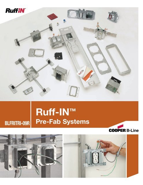
BLFRITRI-09R<br />
Ruff-IN <br />
Pre-Fab Systems
Introduction<br />
Table of Contents<br />
Table of Contents . . . . . . . . . . . . . . . . . . . . . . . . . . . . . . . . . . . . . . . . . . . . . . . . . . . . 2<br />
Ruff-IN & Total Ruff-IN Service Advisors . . . . . . . . . . . . . . . . . . . . . . . 3<br />
Explanation of Offerings . . . . . . . . . . . . . . . . . . . . . . . . . . . . . . . . . . . . . . . . . . . . 4<br />
Quick Ship Program . . . . . . . . . . . . . . . . . . . . . . . . . . . . . . . . . . . . . . . . . . . . . . . . . 5<br />
Configurator Information . . . . . . . . . . . . . . . . . . . . . . . . . . . . . . . . . . . . . . . 6 & 7<br />
Pictorial Index . . . . . . . . . . . . . . . . . . . . . . . . . . . . . . . . . . . . . . . . . . . . . . . . . . . 8 & 9<br />
Ruff-IN Section<br />
Croc-Lok Box Mounting Brackets & Assemblies . . . . . . . . 10 & 11<br />
Telescoping Slider Brackets & Assemblies . . . . . . . . . . . . . . . . 12 & 13<br />
Floor Mount Box Supports & Assemblies . . . . . . . . . . . . . . . . . . 14 & 15<br />
Double Sided Box Support Brackets & Assemblies . . . . . . . 16 & 17<br />
Single Side Box Support & Assemblies . . . . . . . . . . . . . . . . . . . . . . . . . . . 18<br />
Uni-Mount Box Support & Assemblies . . . . . . . . . . . . . . . . . . . . . . . . . 19<br />
Multiple Box Mounting Bracket & Assemblies . . . . . . . . . . . . . 20 & 21<br />
Open Box Support Bracket & Assemblies . . . . . . . . . . . . . . . . . . 22 & 23<br />
Conduit & Box Support Fasteners . . . . . . . . . . . . . . . . . . . . . . . . . . 24 & 25<br />
Electrical Box T-Bar Fasteners & Assemblies . . . . . . . . . . . . . . 26 & 27<br />
T-Bar Fan / Fixture Support . . . . . . . . . . . . . . . . . . . . . . . . . . . . . . . . . . . . . . . 28<br />
Plaster Rings with Wiring Devices . . . . . . . . . . . . . . . . . . . . . . . . . . . . . . . . 29<br />
Ruff-IN MC Cable Solutions Section<br />
Total Ruff-IN . . . . . . . . . . . . . . . . . . . . . . . . . . . . . . . . . . . . . . . . . . . . . . . . . . . . . . . 31<br />
Introduction & Step 1 - Send in drawings . . . . . . . . . . . . . . . . . . . . . . . 32<br />
Step 2 - Project Questionnaire . . . . . . . . . . . . . . . . . . . . . . . . . . . . . . . . . . . . 33<br />
Step 3 - Quotation Package . . . . . . . . . . . . . . . . . . . . . . . . . . . . . . . . . . . . . . . 34<br />
Step 4 - Approval Package . . . . . . . . . . . . . . . . . . . . . . . . . . . . . . . . . . . . . . . . 35<br />
Room Drawing Explanation . . . . . . . . . . . . . . . . . . . . . . . . . . . . . . . . . . . . . . . 36<br />
Labeling & Packaging . . . . . . . . . . . . . . . . . . . . . . . . . . . . . . . . . . . . . . . . . . . . . 37<br />
Ruff-IN Assemblies w/ MC Cable - Option 1 . . . . . . . . . . . . . . . 38 & 39<br />
Ruff-IN Assemblies w/ MC Cable - Option 2 . . . . . . . . . . . . . . . 40 & 41<br />
MC Cable Whips . . . . . . . . . . . . . . . . . . . . . . . . . . . . . . . . . . . . . . . . . . . . . 42 & 43<br />
Accessories<br />
SpecSeal ®† Powershield (Firestop Pads) . . . . . . . . . . . . . . . . . . . . . . . . . 44<br />
Metal Protector Plates . . . . . . . . . . . . . . . . . . . . . . . . . . . . . . . . . . . . . . . . . . . . . 45<br />
Adjustable Plaster Rings . . . . . . . . . . . . . . . . . . . . . . . . . . . . . . . . . . . . . . . . . . . 46<br />
Plaster Rings . . . . . . . . . . . . . . . . . . . . . . . . . . . . . . . . . . . . . . . . . . . . . . . . . . . . . . . 47<br />
Boxes . . . . . . . . . . . . . . . . . . . . . . . . . . . . . . . . . . . . . . . . . . . . . . . . . . . . . . . . . . . . . . . 48<br />
Conduit/Cable Connectors . . . . . . . . . . . . . . . . . . . . . . . . . . . . . . . . . . . . . . . . . 49<br />
Wiring Devices - Receptacles . . . . . . . . . . . . . . . . . . . . . . . . . . . . . . . 50 & 51<br />
Wiring Devices - Switches . . . . . . . . . . . . . . . . . . . . . . . . . . . . . . . . . . 52 & 53<br />
ArrowLink Modular Wiring Devices . . . . . . . . . . . . . . . . . . . . . . . 54 & 55<br />
† Marks shown are property of respective owners.<br />
www.cooperbline.com/Ruff-IN<br />
2<br />
Introduction Ruff-IN Total Ruff-IN Accessories<br />
We Give You<br />
Total Flexibility
How The Service Advisor Works<br />
3<br />
Service Advisors<br />
Ruff-IN Service Advisor<br />
<strong>Cooper</strong> B-Line knows that your time is important! That’s why the color-coding system in this catalog is designed to help<br />
you select products that fit your service needs. Products are marked to indicate the typical lead time for orders of Ruff-IN assemblies.<br />
Customer: How do I select my brackets, boxes, plaster rings, and devices so that I get the quickest turnaround?<br />
Service Advisor: Each part of our selection chart is shown in colors. If any section of a part number is a different<br />
color, the part will typically ship with the longer lead time represented by the colors.<br />
Basic Ruff-IN = 3 to 5 day lead time for quantities of 1000 or less<br />
Ruff-IN w/Wiring Devices = 10 to 15 day lead time for quantities of 500 or less.<br />
Non Stock Components = Call factory for lead time.<br />
Example: BB216TS - 2 10 40 A - P GBW Call factory for lead time<br />
(from page 12) because of the Non Stock<br />
Lead time(days) 3-5 3-5 3-5 3-5 3-5 3-5 call wiring device.<br />
factory<br />
Changing the part number from GBW to EBW will change the coding to yellow for the wiring device.<br />
The new lead time for the assembly would be 10-15 working days because of the standard device.<br />
Ruff-IN MC Cable Solutions Service Advisor<br />
New Service Advisor<br />
Ruff-IN with MC Cables Service Advisor<br />
■ MC Cable Whips Only = 3-5 days for Quantities of 1000 or less<br />
■ Ruff-IN with MC cable = 15-20 days for Quantities of 1000 or less<br />
■ Total Ruff-IN Quotation = 1-5 days*<br />
■ Total Ruff-IN Order = 10-20 days*<br />
* Lead time varies depending on the project scope<br />
Introduction
Introduction<br />
Explanation of Offerings<br />
<strong>Cooper</strong> B-Line Has The Total Pre-Fab Offering…<br />
No matter what your preference for pre-fab may be, <strong>Cooper</strong> B-Line has it!<br />
Choose the pre-fab offering below that best fits your needs:<br />
Basic Ruff-IN Offering Contents: Bracket, Box, Mud Ring, Ground Wire<br />
• Ideal solution for a contractor sampling pre-fab for the first time<br />
that wants to keep the control of his or her project.<br />
• Published lead times of 3-5 days ARO, and NEXT DAY<br />
SHIPPING ON (16) QUICK-SHIP ASSEMBLIES.<br />
Ruff-IN with Wiring Devices<br />
Offering Contents: Bracket, Box, Mud Ring, Wiring Assembly, Device or ArrowLink Connector, Protective Cover Plate<br />
• Assemblies are pre-wired for quick plug-and-play installation<br />
using Wago ®† or wire nut connectors.<br />
• Choose from over 100 cataloged device options<br />
• <strong>Cooper</strong> Wiring Device's ArrowLink connector is offered in a<br />
pre-wired Ruff-IN assembly.<br />
• Using the Ruff-IN Configurator, design each part number<br />
included in your project BOM, then click on icons to instantly<br />
view assembly and wire configuration drawings.<br />
Ruff-IN with MC cables<br />
Offering Contents: Basic Ruff-IN with Wiring Assembly, Device or ArrowLink<br />
Connector, Protective Cover Plate, MC Cable whip with<br />
MC connector(s)<br />
• Pre-wired Ruff-IN assemblies with devices and a pre-cut MC<br />
cable whip attached.<br />
• Whip lengths available in 5-foot increments.<br />
• Includes option to order MC cable whips only.<br />
• Offering explained further on pages 38-43.<br />
Total Ruff-IN Offering Contents: Engineering Take-off Service, Ruff-IN Assemblies, and<br />
MC Cable Whips<br />
• Perfect for a contractor interested in trying pre-fab for the first time<br />
that needs the engineering and assembly expertise of <strong>Cooper</strong> B-Line.<br />
• Industry leading, published lead times for Total Ruff-IN quotation<br />
responses and order assembly.<br />
• For more details, see pages 30-37.<br />
† Marks shown are property of respective owners.<br />
4
Programs<br />
Distributor Quick Ship Program<br />
Next Day Shipping Available on<br />
12 Ruff-IN Assemblies & 16 Rapid Ring Assemblies<br />
BBF18-1104DA BB76-1104D BB216TS-1104D<br />
Ruff-IN Quick Ship Pre-Fab Assemblies<br />
5<br />
• No need to request a lead time, order<br />
today and we’ll ship out of stock<br />
tomorrow!<br />
CBL Part # UPC # Description Maximum<br />
BBF Series Floor-mount<br />
Order Qty.<br />
BBF18-1104DA 78205154072 18" BBF floor-mount, 1-gang 5 /8" plaster ring, TP403 box, stranded ground wire 50<br />
BBF18-1104D 78205154065 18" BBF floor-mount, 1-gang 5 /8" plaster ring, TP403 box, solid ground wire 50<br />
BBF18-1124DA 78205155199 18" BBF floor-mount, 1-gang 3 /4" plaster ring, TP403 box, stranded ground wire 25<br />
BBF18-1124D 78205154176 18" BBF floor-mount, 1-gang 3 /4" plaster ring, TP403 box, solid ground wire 125<br />
Double-Sided Box Support<br />
BB76-1104DA 78205155200 6" Double-sided box support 1-gang 5 /8" plaster ring, TP403 box, stranded ground wire 100<br />
BB76-1104D 78205138768 6" Double-sided box support 1-gang 5 /8" plaster ring, TP403 box, solid ground wire 25<br />
BB76-1124DA 78205154049 6" Double-sided box support 1-gang 3 /4" plaster ring, TP403 box, stranded ground wire 50<br />
BB76-1124D 78205138771 6" Double-sided box support 1-gang 3 /4" plaster ring, TP403 box, solid ground wire 25<br />
Telescoping Slider Bracket<br />
BB216TS-1104DA 78205139289 16" Telescoping Slider Brkt,1-gang 5 /8" plaster ring, TP403 box, stranded ground wire 25<br />
BB216TS-1104D 78205138619 16" Telescoping Slider Brkt, 1-gang 5 /8" plaster ring, TP403 box, solid ground wire 25<br />
BB216TS-1124DA 78205139292 16" Telescoping Slider Brkt, 1-gang 3 /4" plaster ring, TP403 box, stranded ground wire 25<br />
BB216TS-1124D 78205138621 16" Telescoping Slider Brkt, 1-gang 3 /4" plaster ring, TP403 box, solid ground wire 250<br />
Rapid Ring Quick Ship Pre-Fab Assemblies<br />
BBF18-1RR4DA 78205176289 18" BBF floor-mount, 1-gang Rapid Ring, TP403 box, stranded ground wire 50<br />
BBF18-1RR4D 78205176290 18" BBF floor-mount, 1-gang Rapid Ring, TP403 box, solid ground wire 50<br />
BBF18-2RR4DA 78205176084 18" BBF floor-mount, 2-gang Rapid Ring, TP403 box, stranded ground wire 50<br />
BBF18-2RR4D 78205176293 18" BBF floor-mount, 2-gang Rapid Ring, TP403 box, solid ground wire 50<br />
BB76-1RR4DA 78205176085 6" Double-sided box support 1-gang Rapid Ring, TP403 box, stranded ground wire 50<br />
BB76-1RR4D 78205176301 6" Double-sided box support 1-gang Rapid Ring, TP403 box, solid ground wire 50<br />
BB76-2RR4DA 78205176302 6" Double-sided box support 2-gang Rapid Ring, TP403 box, stranded ground wire 50<br />
BB76-2RR4D 78205176303 6" Double-sided box support 2-gang Rapid Ring, TP403 box, solid ground wire 50<br />
BB216TS-1RR4DA 78205176294 16" Telescoping Slider Brkt,1-gang Rapid Ring, TP403 box, stranded ground wire 50<br />
BB216TS-1RR4D 78205176295 16" Telescoping Slider Brkt, 1-gang Rapid Ring, TP403 box, solid ground wire 50<br />
BB216TS-2RR4DA 78205176296 16" Telescoping Slider Brkt, 2-gang Rapid Ring, TP403 box, stranded ground wire 50<br />
BB216TS-2RR4D 78205176297 16" Telescoping Slider Brkt, 2-gang Rapid Ring, TP403 box, solid ground wire 50<br />
BB216TS-1RR4DA 78205176088 16" Telescoping Brkt with Croc Lok ,1-gang Rapid Ring, TP403 box, stranded ground wire 50<br />
BB216TS-1RR4D 78205176298 16" Telescoping Brkt with Croc Lok, 1-gang Rapid Ring, TP403 box, solid ground wire 50<br />
BB216TS-2RR4DA 78205176299 16" Telescoping Brkt with Croc Lok, 2-gang Rapid Ring, TP403 box, stranded ground wire 50<br />
BB216TS-2RR4D 78205176300 16" Telescoping Brkt with Croc Lok, 2-gang Rapid Ring, TP403 box, solid ground wire 50<br />
Double Sided Box<br />
Support with<br />
Rapid Ring<br />
See Ruff-IN Pre-Fab Systems brochure for complete<br />
product information and part numbers.<br />
Telescoping Slider<br />
Bracket with<br />
Rapid Ring<br />
Introduction
Introduction<br />
Ruff-IN Configurator<br />
Introducing <strong>Cooper</strong> B-Line’s Ruff-IN Configurator -<br />
Developed to be the ideal solution for creating a project bill of material.<br />
<strong>Download</strong> the Ruff-IN configurator at www.cooperbline.com/ruff-in and see for yourself how easy it is<br />
to navigate through the component selection process!<br />
Create Assembly Selection Tab<br />
For assemblies that<br />
include wiring devices,<br />
the configurator<br />
provides a wiring<br />
configuration drawing<br />
that details exactly how<br />
the wiring device will<br />
be wired in the<br />
assembly.<br />
Wiring Configuration Drawing<br />
Note: Voice Demo Training Video Tutorial is available at<br />
www.cooperbline.com/ruff-in<br />
6<br />
Determine project<br />
savings when using<br />
Ruff-IN assemblies<br />
by clicking on the<br />
link to the Ruff-IN<br />
Labor Savings<br />
Calculator
Organize Project<br />
BOMs to ship by<br />
specific room and/or<br />
floor<br />
Click to automatically<br />
request a quote for<br />
your project!<br />
3-D Assembly Drawing<br />
Ruff-IN Configurator<br />
7<br />
Instantly view a 3-D<br />
assembly drawing of<br />
your configured<br />
assembly<br />
Project Rooms/Floors Tab<br />
Project Summary Tab<br />
Introduction
Introduction<br />
Croc-Lok Box Mount Bracket<br />
Pages 10 & 11<br />
Single Sided Box Support<br />
Page 18<br />
Conduit & Box Support Fasteners<br />
Pages 24 & 25<br />
Pictorial Index<br />
Total Ruff-IN Steps 1 & 2<br />
Send in Drawings and Complete Project<br />
Questionnaire Pages 32 & 33<br />
Ruff-IN <br />
Assemblies with MC Cable - Option 1<br />
38 &39<br />
Telescoping Slider Bracket<br />
Pages 12 & 13<br />
Uni-Mount Box Support<br />
Page 19<br />
Electrical Box T-Bar Fasteners<br />
Pages 26 & 27<br />
Ruff-IN Contractor Review Sheet (PF-APPROVALFORM-RUFFIN)<br />
Job Name:<br />
PO #:<br />
B-Line Order #:<br />
Initial for Approval<br />
Shipdate for Complete Order<br />
(For multiple shipdate option see page 2)<br />
Initial for Approval<br />
Project Scope<br />
CONTRACTOR SIGNATURE OF APPROVAL FOR ASSEMBLY DRAWINGS<br />
I certify the assembly drawings and other quantities presented on _____________ have been reviewed and are correct.<br />
I am aware that any changes requested and/or made to these drawings could extend the project lead time.<br />
Contractor Name Contractor Signature<br />
CONTRACTOR SIGNATURE OF APPROVAL FOR ROOM DRAWINGS<br />
I certify the room drawings detailing assembly and whip location within each room that are presented on ___________<br />
have been reviewed and are correct. I am aware that any changes requested and/or made to these drawings could<br />
extend the project lead time. Contractor Name Contractor Signature<br />
* Fax this sheet to (618-654-9191, ATTN: Ruff-IN<br />
* Email approval to bline.ruffin@cooperindustries.com is also acceptable<br />
Total Ruff-IN Steps 3 & 4<br />
Quotation & Approval Packages<br />
Pages 34 & 35<br />
8<br />
Floor Mount Box Support<br />
Pages 14 & 15<br />
Multiple Box Mounting Bracket<br />
Pages 20 & 21<br />
Fan/Fixture Hanger Assembly<br />
Page 28<br />
CONTRACTOR SUGGESTED DATE<br />
Attachment:<br />
Ruff-IN<br />
Assemblies with MC Cable - Option 2<br />
Pages 40 & 41<br />
Double Sided Box Support<br />
Pages 16 & 17<br />
Open Box Support Bracket<br />
Pages 22 & 23<br />
Plaster Rings With Wiring Devices<br />
Page 29<br />
Room Drawing Explanation,<br />
Labeling & Packaging<br />
Pages 36 & 37<br />
Ruff-IN<br />
MC Cable Whips<br />
Pages 42 & 43
Firestop Pads<br />
Page 45<br />
Cable & Conduit Connectors<br />
Page 49<br />
Protector Plates<br />
Page 46<br />
Adj. Plaster Rings<br />
Page 47<br />
Wiring Devices - Receptacles<br />
Pages 50 & 51<br />
Wiring Devices - Switches<br />
Pages 52 & 53<br />
• ArrowLink is available with every bracket option that includes the choice<br />
to add a wiring device. Each brochure page includes information on how<br />
ArrowLink can be added to an assembly.<br />
• Assemblies will be pre-wired with ArrowLink connector end included to<br />
allow for quick cable installation.<br />
• Assemblies include a cover plate attached to the mud ring for additional<br />
protection.<br />
• The ArrowLink Modular devices are sold<br />
separately. See your local <strong>Cooper</strong> Wiring<br />
Device representative for details.<br />
• For more information on ArrowLink<br />
Modular Devices see pages 54 & 55.<br />
ArrowLink Modular Wiring Devices with Ruff-IN Pre-Fab Assemblies<br />
The ArrowLink Connector end is now available as an accessory in the Ruff-IN Pre-Fab Systems offering.<br />
Pages 54 & 55<br />
9<br />
Pictorial Index<br />
Plaster Rings<br />
Page 47<br />
Electrical Boxes<br />
Page 48<br />
Introduction
Ruff-IN<br />
UPC/Part<br />
Number<br />
CROC-LOK Box Mounting Bracket<br />
BB216TCL<br />
BB2CL<br />
<strong>Catalog</strong><br />
Number<br />
BB2CL-4D BB2CL-2104DA-WAAR<br />
BB2CL<br />
installed on<br />
BB2-16T<br />
Features<br />
Telescoping Bar with CROC-LOK Assemblies<br />
• The tool-less design enables Croc-Lok assemblies to be field<br />
installed in less than 4 seconds. Simply squeeze, secure<br />
and walk away.<br />
• Outlet boxes mount to the Croc-Lok with single screw.<br />
• The Croc-Lok Box Mounting Bracket is an improved version<br />
of the current BB2TS Slider Bracket.<br />
• Recently redesigned to include raised dimples that lock into<br />
holes on the telescoping bar.<br />
• Redesign includes screw holes in the face plate, which<br />
create the option to screw the Croc-Lok to a telescoping bar<br />
Stud<br />
Spacing<br />
Features<br />
• The Croc-Lok Box Mounting Bracket is an improved version of the<br />
current BB2TS Slider Bracket.<br />
• The narrow width of the Croc-Lok allows for up to three - 4” boxes<br />
to be installed within a 16” stud spacing, and up to four - 4” boxes<br />
within a 24” stud spacing.<br />
• Its design offers placement flexibility by locking in place firmly at any<br />
position along the telescoping bar.<br />
• Croc-Lok box assemblies are sold with or without telescoping bars.<br />
To reduce the lines on your BOM consider ordering Croc-Lok box<br />
assemblies and field install.<br />
• Croc-Lok box assemblies can be attached before or after the<br />
telescoping bar is mounted in the stud wall.<br />
• <strong>Download</strong> the Ruff-IN configurator for free at<br />
www.cooperbline.com/ruff-in and see for yourself how much easier<br />
it allows you to create Ruff-IN part numbers.<br />
Read safety/installation instruction sheets in packages before use. These products are designed for positioning only. No load rating.<br />
10<br />
Description<br />
782051 51291 BB2CL N/A Croc-Lok only 50<br />
782051 51292 BB216TCL 11” to 16” BB2-16T with Croc-Lok 20<br />
782051 51293 BB224TCL 15” to 24” BB2-24T with Croc-Lok 20<br />
U.S. Patent # 8,403,277<br />
Note: Secures to <strong>Cooper</strong> B-Line BB2-16T and BB2-24T telescoping brackets only. For a standard 21 /8” deep box, the stud<br />
depth must be 31 /2” or greater. For a shallow 11 /2” deep box, the stud depth must be 21 /2” or greater.<br />
Box<br />
Qty<br />
Basic Ruff-IN = 3-5 day lead-time for quantities of 1000 or less.<br />
Ruff-IN with Wiring Devices = 10-15 day lead-time for quantities of 500 or less.<br />
Non Stock Components = Call factory for lead-time.
CROC-LOK Box Mounting Bracket Assemblies<br />
•• Example Part Number shown below<br />
BB216TCL -110 4D A _ - _ _ _ _ _ _ -WAAR - _ _ _ _ - _ _ _ _ _ _ - _ _<br />
1 2 3 4 5<br />
6 7 8 9 8 10 8 11 12 2 4 5 6 7 8 9 8 10 8 11 12<br />
Step 1 Step 2 Step 3<br />
Step 1 - Basic Ruff-In<br />
1 Stud Spacing<br />
BB216TCL = 11” to 18” Mounting Bar &<br />
Croc-Loc Assembly<br />
BB224TCL = 15” to 26” Mounting Bar &<br />
Croc-Loc Assembly<br />
BB2CL = Croc-Loc Assembly Only<br />
2<br />
Plaster Ring Style (see ps. 47)<br />
1 = One Device<br />
2 = Two Device<br />
R = Round<br />
1AJ = One Device Adjustable *<br />
2AJ = Two Device Adjustable *<br />
Blank = Box Only<br />
Plaster Ring Size<br />
04 = 1 /4” Raise<br />
08 = 1 /2” Raise<br />
10 = 5 /8” Raise<br />
12 = 3 /4” Raise<br />
16 = 1” Raise<br />
20 = 11 /4” Raise<br />
24 = 11 3<br />
/2” Raise<br />
32 = 2” Raise<br />
Blank = Box Only or<br />
Adjustable Plaster Ring<br />
Box Style (see pg. 48)<br />
4D = 4” Sq., 21 /8” Deep<br />
436 = 4” Sq., 21 /8” Deep, 1” KO<br />
4 = 4” Sq., 11 /2” Deep<br />
432 = 4” Sq., 21 /8” Deep, 3 /4” KO<br />
5D = 411 /16” Sq., 21 /8” Deep<br />
560 = 411 /16” Sq., 21 /8” Deep, 1” KO<br />
5 = 411 /16” Sq., 11 /2” Deep<br />
554 = 411 /16” Sq., 21 /8” Deep, 3 4<br />
/4” KO<br />
5 Ground Wire<br />
(Pre-installed devices require stranded wire)<br />
Blank = Solid Ground Wire<br />
A = Stranded Ground Wire<br />
N = No Ground Wire<br />
6 Firestop Pad (see pg. 45)<br />
Blank = No Pad<br />
F = Pad Installed<br />
For Installation Of One Box For Installation Of Second Box - If Desired<br />
Step 2 - Connectors<br />
7 Connector Top Left KO<br />
Blank = No Attachment<br />
L = Attachment Present<br />
Connector Type (see pg. 49)<br />
Blank = None<br />
A = QLK50S ( 1 /2” single MC)<br />
B = QLK50D ( 1 /2” double MC)<br />
C = QLK75 ( 3 /4” single MC)<br />
D = SSBC50 ( 1 /2” EMT Connector)<br />
E = SSBC75 ( 3 8<br />
/4” EMT Connector)<br />
F = SSBC100 (1” EMT Connector)<br />
9 Connector Top Middle KO<br />
Blank = No Attachment<br />
M = Attachment Present<br />
10 Connector Top Right KO<br />
Blank = No Attachment<br />
R = Attachment Present<br />
* One device adjustable plaster<br />
rings are set at 3 /4” raise and can<br />
be adjusted to 1 1 /2” raise.<br />
Two device adjustable plaster rings<br />
are set at 5 /8” raise and can be<br />
adjusted to 1 1 /2” raise.<br />
Adjustable plaster ring can only<br />
be used on 4” sq. - 2 1 /8” deep<br />
boxes.<br />
•• BB216TCL-1104DA-WAAR BB216TCL-1104DA-24DA-WAAR<br />
Read safety/installation instruction sheets in packages before use. These products are designed for positioning only. No load rating.<br />
11<br />
Step 1 Step 2 Step 3<br />
Step 3 - Wiring Devices<br />
Wire Configuration<br />
P = Pigtails w/4 Hole 1Wago ®†<br />
(all receptacles installed w/ground up)<br />
R = Pigtails w/4 Hole Wago ®†<br />
11<br />
(all receptacles installed w/ground down)<br />
W = No Pigtails Wires Contained Inside<br />
Box (all receptacles installed w/ground up)<br />
Y = No Pigtails Wires Contained Inside Box<br />
(all receptacles installed w/ground down)<br />
M = Pigtails w/ Bare Wire Ends extending from<br />
top KOs, Twist-On Wire Connectors Inside Box<br />
(all receptacles installed w/ground up)<br />
N = Pigtails w/ Bare Wire Ends extending from<br />
top KOs, Twist-On Wire Connectors Inside Box<br />
(all receptacles installed w/ground down)<br />
Note: P, R, M and N configurations not available<br />
if KO connectors are installed on the outlet box<br />
12<br />
Device Type or ArrowLink<br />
Connector Options<br />
Standard Device Type<br />
(see pgs. 50-53)<br />
3 Letter Designator For 1 Device<br />
Two 3 Letter Designators For 2 Different Devices<br />
One 3 Letter Designator For 2 Of The Same Device<br />
ArrowLink Connector Options<br />
(for more information see pgs. 54-55)<br />
MCR = ArrowLink Connector, Receptacle/GFCI<br />
MCS = ArrowLink Connector, Single-Pole Switch<br />
† Marks shown are property of respective owners.<br />
Ruff-IN
Ruff-IN<br />
BB216TS<br />
BB224TS<br />
Telescoping Slider Brackets<br />
UPC/Part<br />
Number<br />
<strong>Catalog</strong><br />
Number<br />
Telescoping Slider Bracket Assemblies<br />
Features<br />
• The industry’s only fully adjustable pre-fab bracket - fits<br />
a range of stud spacings and both 1 1/2” and 2 1/8” deep<br />
boxes.<br />
• Box can be attached to slider bracket before or after<br />
slider is installed on telescoping bracket.<br />
• Box location can be field-adjusted by moving slider<br />
along telescoping bracket.<br />
• Pre-assembled units available with two (2) boxes<br />
if desired.<br />
Stud<br />
Spacing<br />
Features<br />
• Ruff-IN assemblies available with box, plaster ring and<br />
ground wire.<br />
• Wiring devices available installed with 2 1/8” deep boxes.<br />
• Metal protector plate provided with all wiring device<br />
assemblies.<br />
• Fire stop pad and cable/conduit connectors can also be<br />
pre-installed if desired.<br />
• Next day shipping available on (4) BB216TS assemblies,<br />
see page 5 for more information on the Ruff-IN Quick<br />
Ship Program.<br />
• <strong>Download</strong> the Ruff-IN configurator for free at<br />
www.cooperbline.com/ruff-in and see for yourself how<br />
much easier it allows you to create Ruff-IN part<br />
numbers.<br />
Read safety/installation instruction sheets in packages before use. These products are designed for positioning only. No load rating.<br />
12<br />
Description<br />
782051 38614 BB216TS 11” to 18” BB2-16T with Slider Bracket 20<br />
782051 38628 BB224TS 15” to 26” BB2-24T with Slider Bracket 20<br />
782051 38613<br />
Patent # 7,472,875<br />
BB2TS -- Slider Bracket Only 50<br />
BB216TS-1104D<br />
BB216TS-2104D-14DN<br />
BB216TS-2104DA-LARA-WKAV-14DN<br />
•• BB216TS-2104DA-PGBW<br />
Box<br />
Qty
Telescoping Slider Bracket Assemblies<br />
•• Example Part Number from page 12<br />
BB216TS -210 4D A _ - _ _ _ _ _ _ -PGBW - _ _ _ _ - _ _ _ _ _ _ - _ _<br />
1 2 3 4 5<br />
6 7 8 9 8 10 8 11 12 2 4 5 6 7 8 9 8 10 8 11 12<br />
Step 1 Step 2 Step 3<br />
Step 1 - Basic Ruff-In<br />
1<br />
Stud Spacing<br />
BB216TS = 11” - 18”<br />
BB224TS = 15” - 26”<br />
2 Plaster Ring Style (see pg. 47)<br />
1 = One Device<br />
2 = Two Device<br />
R = Round<br />
1AJ = One Device Adjustable *<br />
2AJ = Two Device Adjustable *<br />
Blank = Box Only<br />
Plaster Ring Size<br />
04 = 1 /4” Raise<br />
08 = 1 /2” Raise<br />
10 = 5 /8” Raise<br />
12 = 3 /4” Raise<br />
16 = 1” Raise<br />
20 = 11 /4” Raise<br />
24 = 11 3<br />
/2” Raise<br />
32 = 2” Raise<br />
Blank = Box Only or<br />
Adjustable Plaster Ring<br />
Box Style (see pg. 48)<br />
4D = 4” Sq., 21 /8” Deep<br />
436 = 4” Sq., 21 /8” Deep, 1” KO<br />
4 = 4” Sq., 11 /2” Deep<br />
432 = 4” Sq., 21 /8” Deep, 3 /4” KO<br />
5D = 411 /16” Sq., 21 /8” Deep<br />
560 = 411 /16” Sq., 21 /8” Deep, 1” KO<br />
5 = 411 /16” Sq., 11 /2” Deep<br />
554 = 411 /16” Sq., 21 /8” Deep, 3 4<br />
/4” KO<br />
5 Ground Wire<br />
(Pre-installed devices require stranded wire)<br />
Blank = Solid Ground Wire<br />
A = Stranded Ground Wire<br />
N = No Ground Wire<br />
6 Firestop Pad (see pg. 45)<br />
Blank = No Pad<br />
F = Pad Installed<br />
For Installation Of One Box For Installation Of Second Box - If Desired<br />
Step 2 - Connectors<br />
7 Connector Top Left KO<br />
Blank = No Attachment<br />
L = Attachment Present<br />
Connector Type (see pg. 49)<br />
Blank = None<br />
A = QLK50S ( 1 /2” single MC)<br />
B = QLK50D ( 1 /2” double MC)<br />
C = QLK75 ( 3 /4” single MC)<br />
D = SSBC50 ( 1 /2” EMT Connector)<br />
E = SSBC75 ( 3 8<br />
/4” EMT Connector)<br />
F = SSBC100 (1” EMT Connector)<br />
9 Connector Top Middle KO<br />
Blank = No Attachment<br />
M = Attachment Present<br />
10 Connector Top Right KO<br />
Blank = No Attachment<br />
R = Attachment Present<br />
* One device adjustable plaster<br />
rings are set at 3 /4” raise and can<br />
be adjusted to 1 1 /2” raise.<br />
Two device adjustable plaster rings<br />
are set at 5 /8” raise and can be<br />
adjusted to 1 1 /2” raise.<br />
Adjustable plaster ring can only<br />
be used on 4” sq. - 2 1 /8” deep<br />
boxes.<br />
Read safety/installation instruction sheets in packages before use. These products are designed for positioning only. No load rating.<br />
13<br />
Step 1 Step 2 Step 3<br />
Step 3 - Wiring Devices<br />
Wire Configuration<br />
P = Pigtails w/4 Hole 1Wago ®†<br />
(all receptacles installed w/ground up)<br />
R = Pigtails w/4 Hole Wago ®†<br />
11<br />
(all receptacles installed w/ground down)<br />
W = No Pigtails Wires Contained Inside<br />
Box (all receptacles installed w/ground up)<br />
Y = No Pigtails Wires Contained Inside Box<br />
(all receptacles installed w/ground down)<br />
M = Pigtails w/ Bare Wire Ends extending from<br />
top KOs, Twist-On Wire Connectors Inside Box<br />
(all receptacles installed w/ground up)<br />
N = Pigtails w/ Bare Wire Ends extending from<br />
top KOs, Twist-On Wire Connectors Inside Box<br />
(all receptacles installed w/ground down)<br />
Note: P, R, M and N configurations not available<br />
if KO connectors are installed on the outlet box<br />
12<br />
Device Type or ArrowLink<br />
Connector Options<br />
Standard Device Type<br />
(see pgs. 50-53)<br />
3 Letter Designator For 1 Device<br />
Two 3 Letter Designators For 2 Different Devices<br />
One 3 Letter Designator For 2 Of The Same Device<br />
ArrowLink Connector Options<br />
(for more information see pgs. 54-55)<br />
MCR = ArrowLink Connector, Receptacle/GFCI<br />
MCS = ArrowLink Connector, Single-Pole Switch<br />
† Marks shown are property of respective owners.<br />
Basic Ruff-IN = 3-5 day lead-time for quantities of 1000 or less.<br />
Ruff-IN with Wiring Devices = 10-15 day lead-time for quantities of 500 or less.<br />
Non Stock Components = Call factory for lead-time.<br />
Ruff-IN
Ruff-IN<br />
BBF18<br />
BBFC<br />
Floor Mount Box Supports<br />
BBFxxC<br />
Patent #<br />
7956285B2 & 5595362<br />
Features<br />
• New BBF floorstand provides the most rigid support in the industry.<br />
• Far-side support accommodates 6”, 51/2”, 31/2”, and 21/2” stud depths.<br />
• Fold-out tab built-in to attach floor stand to stud if desired.<br />
• Integral “wings” provide rigid support when floorstand is mounted between studs.<br />
• Optional cable containment clip securely attaches to floorstand without hardware.<br />
• Finish: Pre-galvanized.<br />
UPC/Part<br />
Number<br />
<strong>Catalog</strong><br />
Number<br />
Read safety/installation instruction sheets in packages before use. These products are designed for positioning only. No load rating.<br />
14<br />
Box Center<br />
Height<br />
Box<br />
Qty<br />
782051 52944 BBF15 15” Floorstand 25<br />
782051 52945 BBF18 18” Floorstand 25<br />
782051 52946 BBF24 24” Floorstand 25<br />
782051 52947 BBFC Cable Containment Clip 25<br />
782051 52948 BBF15C 15” Floorstand<br />
with Cable Containment Clip<br />
25<br />
782051 52949 BBF18C 18” Floorstand<br />
with Cable Containment Clip<br />
25<br />
782051 52950 BBF24C 24” Floorstand<br />
with Cable Containment Clip<br />
25<br />
Floor Mount/Single Side Box Support Combo Assemblies<br />
BBF24-31104DA-2104DA<br />
Features<br />
• Wiring devices available installed with 21/8” deep boxes.<br />
• Bottom kick plate depth shortened to slide under stud track more easily.<br />
• Double-sided bracket can be ganged to floor stand for multiple box applications.<br />
• Patented Marty-Mouse ears enable boxes to be secured in place with or without<br />
the plaster rings.<br />
• Available in three (3) bracket sizes - 15”, 18”, and 24”.<br />
• Next day shipping available on (4) BBF18 assemblies, see page 5 for<br />
more information on the Ruff-IN Quick-Ship Program.<br />
• <strong>Download</strong> the Ruff-IN configurator for free at www.cooperbline.com/ruff-in<br />
and see for yourself how much easier it allows you to create Ruff-IN part<br />
numbers.
BBF15 = 15”<br />
BBF18 = 18”<br />
BBF24 = 24”<br />
Floor Mount Box Support & Assemblies<br />
•• Example Part Number shown below<br />
BBF18 _ - _ 2 10 4D A _ - _ _ _ _ - W GDW - _ _ _ _ - _ _ _ _ - _ _ __<br />
1 2 3 4 5 6 7 8 9 10 11 12 13 14<br />
Step 1 Step 2 Step 3<br />
For Installation Of One Box<br />
Step 1 - Basic Ruff-In<br />
1<br />
Box Height<br />
2 Cable Containment<br />
C = Include cable containment<br />
Blank = Do not include cable containment<br />
Stud Depth for Optional Second Box<br />
Blank = No additional bracket<br />
3 = 31 /2” & 21 /2”<br />
4 = 4”, 31 /2” & 21 /2”<br />
5 = 6”, 51 /2”, 31 /2” & 21 3<br />
/2”<br />
4 Plaster Ring Style (see pg. 47)<br />
1 = One Device<br />
2 = One Device<br />
R = Round<br />
1AJ = One Device Adjustable *<br />
2AJ = Two Device Adjustable *<br />
Blank = Box Only<br />
Plaster Ring Size<br />
04 = 1 /4” Raise<br />
08 = 1 /2” Raise<br />
10 = 5 /8” Raise<br />
12 = 3 /4” Raise<br />
16 = 1” Raise<br />
20 = 11 /4” Raise<br />
24 = 11 5<br />
/2” Raise<br />
32 = 2” Raise<br />
Blank = Box Only or<br />
Adjustable Plaster Ring<br />
Box Style (see pg. 48)<br />
4D = 4” Sq., 21 /8” Deep<br />
436 = 4” Sq., 21 /8” Deep, 1” KO<br />
4 = 4” Sq., 11 /2” Deep<br />
432 = 4” Sq., 21 /8” Deep, 3 /4” KO<br />
5D = 411 /16” Sq., 21 /8” Deep<br />
560 = 411 /16” Sq., 21 /8” Deep, 1” KO<br />
5 = 411 /16” Sq., 11 /2” Deep<br />
554 = 411 /16” Sq., 21 /8” Deep, 3 /4” KO<br />
431 = 4” Sq., 21 6<br />
/8” Deep, Int. MC Connectors<br />
Blank = Plaster Ring Only<br />
Step 1 - Basic Ruff-In (cont.)<br />
7 Ground Wire<br />
(Pre-installed devices require stranded wire)<br />
Blank = Solid Ground Wire<br />
A = Stranded Ground Wire<br />
N = No Ground Wire<br />
8 Firestop Pad (see pg. 45)<br />
Blank = No Pad<br />
F = Pad Installed<br />
Step 2 - Connectors<br />
9 Connector Top Left KO<br />
Blank = No Attachment<br />
L = Attachment Present<br />
Connector Type (see pg. 49)<br />
Blank = None<br />
A = QLK50S ( 1 /2” single MC)<br />
B = QLK50D ( 1 /2” double MC)<br />
C = QLK75 ( 3 /4” single MC)<br />
D = SSBC50 ( 1 /2” EMT Connector)<br />
E = SSBC75 ( 3 10<br />
/4” EMT Connector)<br />
F = SSBC100 (1” EMT Connector)<br />
11 Connector Top Middle KO<br />
Blank = No Attachment<br />
M = Attachment Present<br />
12 Connector Top Right KO<br />
Blank = No Attachment<br />
R = Attachment Present<br />
* One device adjustable plaster<br />
rings are set at 3 /4” raise and can<br />
be adjusted to 1 1 /2” raise.<br />
Two device adjustable plaster rings<br />
are set at 5 /8” raise and can be<br />
adjusted to 1 1 /2” raise.<br />
Adjustable plaster ring can only<br />
be used on 4” sq. - 2 1 /8” deep<br />
boxes.<br />
Basic Ruff-IN = 3-5 day lead-time for quantities of 1000 or less.<br />
Ruff-IN with Wiring Devices = 10-15 day lead-time for quantities of 500 or less.<br />
Non Stock Components = Call factory for lead-time.<br />
Read safety/installation instruction sheets in packages before use. These products are designed for positioning only. No load rating.<br />
15<br />
4 6 7 8 9 10 11 12 13 14<br />
Step 1 Step 2<br />
For Installation Of Second Box - If Desired<br />
Step 3<br />
Step 3 - Wiring Devices<br />
Wire Configuration<br />
P = Pigtails w/4 Hole Wagos ®†<br />
(all receptacles installed w/ground up)<br />
R = Pigtails w/4 Hole Wago ®†<br />
13<br />
(all receptacles installed w/ground down)<br />
W = No Pigtails Wires Contained Inside<br />
Box (all receptacles installed w/ground up)<br />
Y = No Pigtails Wires Contained Inside Box<br />
(all receptacles installed w/ground down)<br />
M = Pigtails w/ Bare Wire Ends extending from<br />
top KOs, Twist-On Wire Connectors Inside Box<br />
(all receptacles installed w/ground up)<br />
N = Pigtails w/ Bare Wire Ends extending from<br />
top KOs, Twist-On Wire Connectors Inside Box<br />
(all receptacles installed w/ground down)<br />
Note: P, R, M and N configurations not available<br />
if KO connectors are installed on the outlet box<br />
14<br />
Device Type or ArrowLink<br />
Connector Options<br />
Standard Device Type<br />
(see pgs. 50-53)<br />
3 Letter Designator For 1 Device<br />
Two 3 Letter Designators For 2 Different Devices<br />
One 3 Letter Designator For 2 Of The Same Device<br />
ArrowLink Connector Options<br />
(for more information see pgs. 54-55)<br />
MCR = ArrowLink Connector, Receptacle/GFCI<br />
MCS = ArrowLink Connector, Single-Pole Switch<br />
† Marks shown are property of respective owners.<br />
•• BBF18-2104DA-WGDW<br />
BBF15C-1104DA-UMCR<br />
Ruff-IN
Ruff-IN<br />
Double Sided Box Support Bracket<br />
with patented Marty-Mouse Ears<br />
Features<br />
• Double side box support designed for Pre-Fab installations. Unit can be<br />
installed on either side of stud without repositioning box or devices.<br />
• Patented Marty-Mouse Ears feature an innovative keyhole pattern to secure<br />
outlet box to bracket with or without plaster ring.<br />
• Marty-Mouse Ears simplify wiring of pre-fab units. Plaster ring can be<br />
removed for full access to box contents while box remains in place.<br />
• Wider box opening accommodates one or two gang adjustable plaster rings<br />
(B1AJ & B2AJ - see pg. 47).<br />
• Enhanced far-side support stands up during drywall installation and out<br />
performs competitor brackets.<br />
• Finish: Pre-Galvanized<br />
Double Sided Box Support Bracket Assemblies<br />
BB73-1104D<br />
BB73-2104D<br />
BB74<br />
shown<br />
UPC/Part<br />
Number<br />
Features<br />
<strong>Catalog</strong><br />
Number<br />
• Ruff-IN assemblies available with box, plaster ring and ground wire.<br />
• Wiring devices available installed with 2 1/8” deep boxes.<br />
• Metal protector plated provided with all wiring device assemblies.<br />
• Fire stop pad and cable/conduit connectors can also be pre-installed<br />
if desired.<br />
• Next day shipping available on (4) BB76 assemblies, see page 5 for<br />
more information on the Ruff-IN Quick-Ship Program.<br />
• <strong>Download</strong> the Ruff-IN configurator for free at www.cooperbline.com/ruff-in<br />
and see for yourself how much easier it allows you to create Ruff-IN part<br />
numbers.<br />
Read safety/installation instruction sheets in packages before use. These products are designed for positioning only. No load rating.<br />
16<br />
Stud Size<br />
Box<br />
Qty<br />
781011 38645 BB73 31/2” & 21/2” 50<br />
781011 38717 BB74 4”, 31/2” & 21/2” 50<br />
781011 38759 BB76 6”, 51/2”, 31/2”, 21/2” Patent # 5595362<br />
25<br />
BB76-1104D BB73-2104D-LAMARA BB73-2104D-LAMARA-PWAAW •• BB73-2104DA-PAAW
Step 1 - Basic Ruff-In<br />
1<br />
Stud Depth<br />
BB73 = 3 1 /2” & 2 1 /2”<br />
BB74 = 4”, 3 1 /2” & 2 1 /2”<br />
BB76 = 6”, 5 1 /2”, 3 1 /2 & 2 1 /2”<br />
2<br />
Plaster Ring Style (see pg. 47)<br />
1 = One Device<br />
2 = Two Device<br />
R = Round<br />
1AJ = One Device Adjustable *<br />
2AJ = Two Device Adjustable *<br />
Blank = Box Only<br />
Plaster Ring Size<br />
04 = 1 /4” Raise<br />
08 = 1 /2” Raise<br />
10 = 5 /8” Raise<br />
12 = 3 /4” Raise<br />
16 = 1” Raise<br />
20 = 11 /4” Raise<br />
24 = 11 3<br />
/2” Raise<br />
32 = 2” Raise<br />
Blank = Box Only or<br />
Adjustable Plaster Ring<br />
Box Style (see pg. 48)<br />
4D = 4” Sq., 21 /8” Deep<br />
436 = 4” Sq., 21 /8” Deep, 1” KO<br />
4 = 4” Sq., 11 /2” Deep<br />
432 = 4” Sq., 21 /8” Deep, 3 /4” KO<br />
5D = 411 /16” Sq., 21 /8” Deep<br />
560 = 411 /16” Sq., 21 /8” Deep, 1” KO<br />
5 = 411 /16” Sq., 11 /2” Deep<br />
554 = 411 /16” Sq., 21 /8” Deep, 3 /4” KO<br />
431 = 4” Sq., 21 4<br />
/8” Deep, Int. MC Connectors<br />
Blank = Plaster Ring Only<br />
5 Ground Wire<br />
(Pre-installed devices require stranded wire)<br />
Blank = Solid Ground Wire<br />
A = Stranded Ground Wire<br />
N = No Ground Wire<br />
6 Firestop Pad (see pg. 45)<br />
Blank = No Pad<br />
F = Pad Installed<br />
Double Sided Box Support Bracket<br />
•• Example Part Number from page 16<br />
BB73 -210 4D A _ - _ _ _ _ _ _ - P AAW<br />
1 2 3 4 5 6 7 8 9 8 10 8 11 12<br />
Step 1 Step 2 Step 3<br />
Step 2 - Connectors<br />
7 Connector Top Left KO<br />
Blank = No Attachment<br />
L = Attachment Present<br />
Connector Type (see pg. 49)<br />
Blank = None<br />
A = QLK50S ( 1 /2” single MC)<br />
B = QLK50D ( 1 /2” double MC)<br />
C = QLK75 ( 3 /4” single MC)<br />
D = SSBC50 ( 1 /2” EMT Connector)<br />
E = SSBC75 ( 3 8<br />
/4” EMT Connector)<br />
F = SSBC100 (1” EMT Connector)<br />
9 Connector Top Middle KO<br />
Blank = No Attachment<br />
M = Attachment Present<br />
10 Connector Top Right KO<br />
Blank = No Attachment<br />
R = Attachment Present<br />
* One device adjustable plaster<br />
rings are set at 3 /4” raise and can<br />
be adjusted to 1 1 /2” raise.<br />
Two device adjustable plaster rings<br />
are set at 5 /8” raise and can be<br />
adjusted to 1 1 /2” raise.<br />
Adjustable plaster ring can only<br />
be used on 4” sq. - 2 1 /8” deep<br />
boxes.<br />
† Marks shown are property of respective owners.<br />
Read safety/installation instruction sheets in packages before use. These products are designed for positioning only. No load rating.<br />
17<br />
Step 3 - Wiring Devices<br />
Wire Configuration<br />
P = Pigtails w/4 Hole Wago ®†<br />
(all receptacles installed w/ground up)<br />
R = Pigtails w/4 Hole Wago ®†<br />
11<br />
(all receptacles installed w/ground down)<br />
W = No Pigtails Wires Contained Inside<br />
Box (all receptacles installed w/ground up)<br />
Y = No Pigtails Wires Contained Inside Box<br />
(all receptacles installed w/ground down)<br />
M = Pigtails w/ Bare Wire Ends extending from<br />
top KOs, Twist-On Wire Connectors Inside Box<br />
(all receptacles installed w/ground up)<br />
N = Pigtails w/ Bare Wire Ends extending from<br />
top KOs, Twist-On Wire Connectors Inside Box<br />
(all receptacles installed w/ground down)<br />
Note: P, R, M and N configurations not available<br />
if KO connectors are installed on the outlet box<br />
12<br />
Device Type or ArrowLink<br />
Connector Options<br />
Standard Device Type<br />
(see pgs. 50-53)<br />
3 Letter Designator For 1 Device<br />
Two 3 Letter Designators For 2 Different Devices<br />
One 3 Letter Designator For 2 Of The Same Device<br />
ArrowLink Connector Options<br />
(for more information see pgs. 54-55)<br />
MCR = ArrowLink Connector, Receptacle/GFCI<br />
MCS = ArrowLink Connector, Single-Pole Switch<br />
BB76-1104DA-PMCR<br />
(cover plate not shown)<br />
Basic Ruff-IN = 3-5 day lead-time for quantities of 1000 or less.<br />
Ruff-IN with Wiring Devices = 10-15 day lead-time for quantities of 500 or less.<br />
Non Stock Components = Call factory for lead-time.<br />
Ruff-IN
Ruff-IN<br />
Single Sided Box Support & Assemblies<br />
BB4-23<br />
BB4-4<br />
BB4-6<br />
BB423-1104DN<br />
BB423-1104D<br />
•• BB46-1104D<br />
Features<br />
• Improved far-side support prevents box movement in wall cavity.<br />
• Adjustable far-side supports designed to reduce labor.<br />
• Brackets may be piggy-backed in series..<br />
• Ruff-IN assemblies available with box, plaster ring and ground wire.<br />
• Not recommended for pre-installed wiring devices.<br />
See pages 16-17 for an improved Pre-Fab assembly solution.<br />
• <strong>Download</strong> the Ruff-IN configurator for free at www.cooperbline.com/ruff-in<br />
and see for yourself how much easier it allows you to create Ruff-IN part<br />
numbers.<br />
UPC/Part<br />
Number<br />
<strong>Catalog</strong><br />
Number<br />
Single Sided Box Support Bracket Assemblies<br />
1 2 3 4 5 6<br />
Read safety/installation instruction sheets in packages before use. These products are designed for positioning only. No load rating.<br />
18<br />
Stud Size<br />
Box<br />
Qty<br />
781011 18190 BB4-23 31/2” & 21/2” 100<br />
781011 18200 BB4-4 4”, 31/2” & 21/2” 100<br />
781011 18202 BB4-6 6”, 51/2”, 31/2”, 21/2” 100<br />
Stud Depth<br />
BB423 = 31 /2” & 21 /2”<br />
BB44 = 4”, 31 /2” & 21 /2”<br />
BB46 = 6”, 51 /2”, 31 /2 & 21 1<br />
/2”<br />
2 Plaster Ring Style (see pg. 47)<br />
1 = One Device<br />
2 = Two Device<br />
R = Round<br />
1AJ = One Device Adjustable *<br />
Blank = Box Only<br />
Plaster Ring Size<br />
04 = 1 /4” Raise<br />
08 = 1 /2” Raise<br />
10 = 5 /8” Raise<br />
12 = 3 /4” Raise<br />
16 = 1” Raise<br />
20 = 11 /4” Raise<br />
24 = 11 3<br />
/2” Raise<br />
32 = 2” Raise<br />
Blank = Box Only or<br />
Adjustable Plaster Ring<br />
•• Example Part Number<br />
BB46 - 1 10 4D _ _<br />
Box Style (see pg. 48)<br />
4D = 4” Sq., 21 /8” Deep<br />
436 = 4” Sq., 21 /8” Deep, 1” KO<br />
4 = 4” Sq., 11 /2” Deep<br />
432 = 4” Sq., 21 /8” Deep, 3 /4” KO<br />
5D = 411 /16” Sq., 21 /8” Deep<br />
560 = 411 /16” Sq., 21 /8” Deep, 1” KO<br />
5 = 411 /16” Sq., 11 /2” Deep<br />
554 = 411 /16” Sq., 21 /8” Deep, 3 /4” KO<br />
431 = 4” Sq., 21 4 5 Ground Wire<br />
Blank = Solid Ground Wire<br />
A = Stranded Ground Wire<br />
N = No Ground Wire<br />
6 Firestop Pad (see pg. 45)<br />
Blank = No Pad<br />
/8” Deep, Int. MC Connectors<br />
Blank = Plaster Ring Only<br />
F = Pad Installed<br />
* One device adjustable plaster rings are set<br />
at 3 /4” raise and can be adjusted to 1 1 /2” raise.<br />
Adjustable plaster ring can only be used on<br />
4” sq. - 2 1 /8” deep boxes.<br />
Basic Ruff-IN = 3-5 day lead-time for quantities of 1000 or less.<br />
Non Stock Components = Call factory for lead-time.
Features<br />
Uni-Mount Box Support & Assemblies<br />
• Uni-Mount provides a secure box support and features a built-in<br />
plaster ring.<br />
• Rigid bracket design eliminates the need for far-side support.<br />
• Guide tabs ensure alignment on studs.<br />
• Ruff-IN assemblies available with box, plaster ring and ground wire.<br />
• Fire stop pad can be pre-installed in boxes if desired.<br />
• Not recommended for pre-installed wiring devices.<br />
See pages 16-17 for an improved Pre-Fab assembly solution.<br />
• <strong>Download</strong> the Ruff-IN configurator for free at www.cooperbline.com/ruff-in<br />
and see for yourself how much easier it allows you to create Ruff-IN part<br />
numbers.<br />
UPC/Part<br />
Number<br />
<strong>Catalog</strong><br />
Number<br />
Uni-Mount Box Support Assemblies<br />
Read safety/installation instruction sheets in packages before use. These products are designed for positioning only. No load rating.<br />
19<br />
Plaster<br />
Ring<br />
Box<br />
Qty<br />
782051 22768 BB40-08 1/2” raise 50<br />
782051 22771 BB40-10 5/8” raise 50<br />
782051 22772 BB40-12 3/4” raise 50<br />
782051 22773 BB45-08 1/2” raise 50<br />
782051 22774 BB45-10 5/8” raise 50<br />
782051 22775 BB45-12 3/4” raise 50<br />
1 Plaster Ring Style<br />
BB40 = One Device<br />
BB45 = Two Device<br />
Plaster Ring Size<br />
08 = 1 /2” Raise<br />
10 = 5 /8” Raise<br />
12 = 3 2<br />
/4” Raise<br />
•• Example Part Number<br />
BB45 - 10 - 4D _ _<br />
1 2 3 4 5<br />
Box Style (see pg. 48)<br />
4D = 4” Sq., 21 /8” Deep<br />
436 = 4” Sq., 21 /8” Deep, 1” KO<br />
4 = 4” Sq., 11 /2” Deep<br />
432 = 4” Sq., 21 /8” Deep, 3 /4” KO<br />
431 = 4” Sq., 21 3<br />
/8” Deep, Int. MC Connectors<br />
4 Ground Wire<br />
Blank = Solid Ground Wire<br />
A = Stranded Ground Wire<br />
N = No Ground Wire<br />
5 Firestop Pad (see pg. 45)<br />
Blank = No Pad<br />
F = Pad Installed<br />
BB40-10-4DN<br />
•• BB45-10-4D<br />
Basic Ruff-IN = 3-5 day lead-time for quantities of 1000 or less.<br />
Non Stock Components = Call factory for lead-time.<br />
BB40-10<br />
BB45-8<br />
Ruff-IN
Ruff-IN<br />
1<br />
1<br />
Multiple Box Mounting Brackets<br />
2<br />
2<br />
Features<br />
Multiple Box Mounting Bracket Assemblies<br />
BB816-104D-X-1-X<br />
BB816-104D-1-1-X<br />
BB816-104D-X-6-X<br />
3<br />
BB8-16<br />
3<br />
4<br />
BB8-24<br />
Features<br />
• Provides support for multiple boxes or plaster rings<br />
between studs 16” or 24” on center.<br />
• Available factory assembled with plaster rings and/or<br />
boxes with ground wire to reduce labor.<br />
• Custom factory assemblies are ordered by specifying<br />
plaster rings and/or boxes for each bracket position.<br />
UPC/Part<br />
Number<br />
BB816-104D-X-1WGBW-X •• BB816-104D-X-1LARAWKAV-X<br />
Read safety/installation instruction sheets in packages before use. These products are designed for positioning only. No load rating.<br />
20<br />
<strong>Catalog</strong><br />
Number<br />
Stud<br />
Spacing<br />
Box<br />
Qty<br />
781011 02898 BB8-16 16” 25<br />
781011 02900 BB8-24 24” 25<br />
• Custom factory assemblies are ordered by specifying box<br />
information for each position opening.<br />
• Ruff-IN assemblies available with box, plaster ring and ground wire.<br />
• Wiring devices available installed with 2 1/8” deep boxes.<br />
• Metal protector plate provided with all wiring device assemblies.<br />
• Fire stop pad and cable/conduit connectors can be pre-installed in<br />
boxes if desired.<br />
• <strong>Download</strong> the Ruff-IN configurator for free at<br />
www.cooperbline.com/ruff-in and see for yourself how<br />
much easier it allows you to create Ruff-IN part numbers.<br />
BB816-104D-X-1PCAA-X
Multiple Box Mounting Bracket Assemblies<br />
•• Example Part Number from page 20<br />
BB816 - 10 4D _ _ -X_______ _ -1LARA__WKAV -X _ _ _ _ _ _ _ _ -X_______ _<br />
1 2 3 4 5 6 7 8 9 8 10 8 11 12 6 7 8 9 8 10 8 11 12 6 7 8 9 8 10 8 11 12 6 7 8 9 8 10 8 11 12<br />
Step 1 Step 2 Step 3 Step 2 Step 3 Step 2 Step 3 Step 2 Step 3<br />
Step 1 - Basic Ruff-In<br />
Position 1 Opening (if desired) Position 2 Opening (if desired) Position 3 Opening (if desired) Position Opening 4 (if desired)<br />
(on BB824 only)<br />
Step 2 - Connectors<br />
Stud Spacing<br />
BB816 = 16”<br />
BB824 = 24”<br />
Plaster Ring Size<br />
04 = 1 /4” Raise<br />
08 = 1 /2” Raise<br />
10 = 5 /8” Raise<br />
12 = 3 /4” Raise<br />
16 = 1” Raise<br />
20 = 11 /4” Raise<br />
24 = 11 /2” Raise<br />
32 = 2” Raise<br />
Blank = Box Only or Adjustable Plaster Ring<br />
Box Style (see pg. 48)<br />
4D = 4” Sq., 21 /8” Deep<br />
436 = 4” Sq., 21 /8” Deep, 1” KO<br />
4 = 4” Sq., 11 /2” Deep<br />
432 = 4” Sq., 21 /8” Deep, 3 /4” KO<br />
5D = 411 /16” Sq., 21 /8” Deep<br />
560 = 411 /16” Sq., 21 /8” Deep, 1” KO<br />
5 = 411 /16” Sq., 11 /2” Deep<br />
554 = 411 /16” Sq., 21 /8” Deep, 3 /4” KO<br />
431 = 4” Sq., 21 Position<br />
1 = One Device and Box ∆<br />
2 = Two Device and Box ∆<br />
J = One Device Adjustable Ring & Box *∆<br />
3 = One Device Plaster Ring Only<br />
4 = Two Device Plaster Ring Only<br />
5 = Box Only<br />
R = Round Plaster Ring and Box<br />
6 = One Device and Box, No Ground Wire<br />
7 = Two Device and Box, No Ground Wire<br />
8 = Round Plaster Ring and Box,<br />
No Ground Wire<br />
K = Adjustable Plaster Ring and Box,<br />
No Ground Wire<br />
9 = Box Only, No Ground Wire<br />
X = No Attachments<br />
∆ Only Options 1, 2, & J can be used<br />
with wiring devices.<br />
Connector Top Left KO<br />
Blank = No Attachment<br />
L = Attachment Present<br />
Connector Type (see pg. 49)<br />
/8” Deep, Int. MC Connectors Blank = None<br />
A = QLK50S (<br />
Ground Wire<br />
(Pre-installed devices require stranded wire)<br />
Blank = Solid Ground Wire<br />
A = Stranded Ground Wire<br />
N = No Ground Wire<br />
Firestop Pad (see pg. 45)<br />
Blank = No Pad<br />
F = Pad Installed<br />
1 /2” single MC)<br />
B = QLK50D ( 1 /2” double MC)<br />
C = QLK75 ( 3 /4” single MC)<br />
D = SSBC50 ( 1 /2” EMT Connector)<br />
E = SSBC75 ( 3 1 6<br />
2<br />
3<br />
7<br />
8<br />
4<br />
/4” EMT Connector)<br />
F = SSBC100 (1” EMT Connector)<br />
5<br />
9 Connector Top Middle KO<br />
Blank = No Attachment<br />
M = Attachment Present<br />
Note: If different box than called out in Step 1<br />
is used in any position, enter the designator<br />
for the box after the character of the position.<br />
For example ‘14D’ or ‘1432’.<br />
10 Connector Top Right KO<br />
Blank = No Attachment<br />
R = Attachment Present<br />
Basic Ruff-IN = 3-5 day lead-time for quantities of 1000 or less.<br />
Ruff-IN with Wiring Devices = 10-15 day lead-time for quantities of 500 or less.<br />
Non Stock Components = Call factory for lead-time.<br />
Read safety/installation instruction sheets in packages before use. These products are designed for positioning only. No load rating.<br />
21<br />
Step 3 - Wiring Devices<br />
Wire Configuration<br />
P = Pigtails w/4 Hole Wago ®†<br />
(all receptacles installed w/ground up)<br />
R = Pigtails w/4 Hole Wagos ®†<br />
11<br />
(all receptacles installed w/ground down)<br />
W = No Pigtails Wires Contained Inside<br />
Box (all receptacles installed w/ground up)<br />
Y = No Pigtails Wires Contained Inside Box<br />
(all receptacles installed w/ground down)<br />
M = Pigtails w/ Bare Wire Ends extending from<br />
top KOs, Twist-On Wire Connectors Inside Box<br />
(all receptacles installed w/ground up)<br />
N = Pigtails w/ Bare Wire Ends extending from<br />
top KOs, Twist-On Wire Connectors Inside Box<br />
(all receptacles installed w/ground down)<br />
Note: P, R, M and N configurations not available<br />
if KO connectors are installed on the outlet box<br />
12<br />
Device Type or ArrowLink<br />
Connector Options<br />
Standard Device Type<br />
(see pgs. 50-53)<br />
3 Letter Designator For 1 Device<br />
Two 3 Letter Designators For 2 Different Devices<br />
One 3 Letter Designator For 2 Of The Same Device<br />
ArrowLink Connector Options<br />
(for more information see pgs. 54-55)<br />
MCR = ArrowLink Connector, Receptacle/GFCI<br />
MCS = ArrowLink Connector, Single-Pole Switch<br />
† Marks shown are property of respective owners.<br />
* One device adjustable plaster<br />
rings are set at 3 /4” raise and can<br />
be adjusted to 1 1 /2” raise.<br />
Adjustable plaster ring can only<br />
be used on 4” sq. - 2 1 /8” deep<br />
boxes.<br />
Ruff-IN
Ruff-IN<br />
1<br />
1<br />
Open Box Support Mounting Brackets<br />
Features<br />
Open Box Support Mounting Bracket Assemblies<br />
BB716-104D-X-1-X<br />
BB716-105D-2-X-2<br />
2<br />
2<br />
3<br />
BB7-16<br />
3<br />
4<br />
BB7-24<br />
• <strong>Cooper</strong> B-Line’s BB7 Series open box support secures<br />
boxes and plaster rings between studs 16” and 24” on<br />
center.<br />
• Open design allows infinite adjustability, box can be<br />
placed in any horizontal location.<br />
• Stamped markings at 1/4”, 1/2” and 1” increments allow<br />
the installer to easily locate the desired box position.<br />
UPC/Part<br />
Number<br />
Features<br />
BB716-104D-X-2PGDVAAW-X •• BB716-104D-X-2PKAV-X<br />
Read safety/installation instruction sheets in packages before use. These products are designed for positioning only. No load rating.<br />
22<br />
<strong>Catalog</strong><br />
Number<br />
Stud<br />
Spacing<br />
Box<br />
Qty<br />
781011 45325 BB7-16 16” 25<br />
781011 45328 BB7-24 24” 25<br />
• Custom factory assemblies are ordered by specifying box<br />
information and location for each position.<br />
• Ruff-IN assemblies available with box, plaster ring and<br />
ground wire.<br />
• Wiring devices available installed with 2 1/8” deep boxes.<br />
• Metal protector plate provided with all wiring device<br />
assemblies.<br />
• Fire stop pad and cable/conduit connectors can be<br />
pre-installed in boxes if desired.<br />
• <strong>Download</strong> the Ruff-IN configurator for free at<br />
www.cooperbline.com/ruff-in and see for yourself how<br />
much easier it allows you to create Ruff-IN part<br />
numbers.
Open Box Support Mounting Assemblies<br />
•• Example Part Number from page 22<br />
BB716 - 10 4D _ _ - X _______ _ - 2 ______PKAV - X_______ _ - ________ _<br />
1 2 3 4 5 6 7 8 9 8 10 8 11 12 6 7 8 9 8 10 8 11 12 6 7 8 9 8 10 8 11 12 6 7 8 9 8 10 8 11 12<br />
Step 1 Step 2 Step 3 Step 2 Step 3 Step 2 Step 3 Step 2 Step 3<br />
Position 1 Opening (if desired) Position 2 Opening (if desired) Position 3 Opening (if desired) Position Opening 4 (if desired)<br />
(on BB824 only)<br />
Step 1 - Basic Ruff-In<br />
Plaster Ring Size<br />
04 = 1 /4” Raise<br />
08 = 1 /2” Raise<br />
10 = 5 /8” Raise<br />
12 = 3 /4” Raise<br />
16 = 1” Raise<br />
20 = 11 /4” Raise<br />
24 = 11 2<br />
/2” Raise<br />
32 = 2” Raise<br />
Box Style (see pg. 48)<br />
4D = 4” Sq., 21 /8” Deep<br />
436 = 4” Sq., 21 /8” Deep, 1” KO<br />
4 = 4” Sq., 11 /2” Deep<br />
432 = 4” Sq., 21 /8” Deep, 3 /4” KO<br />
5D = 411 /16” Sq., 21 /8” Deep<br />
560 = 411 /16” Sq., 21 /8” Deep, 1” KO<br />
5 = 411 /16” Sq., 11 /2” Deep<br />
554 = 411 /16” Sq., 21 /8” Deep, 3 /4” KO<br />
431 = 4” Sq., 21 3<br />
/8” Deep, Int. MC Connectors<br />
4 Ground Wire<br />
(Pre-installed devices require stranded wire)<br />
Blank = Solid Ground Wire<br />
A = Stranded Ground Wire<br />
N = No Ground Wire<br />
5 Firestop Pad (see pg.45)<br />
Blank = No Pad<br />
F = Pad Installed<br />
Step 2 - Connectors<br />
1 Stud Spacing<br />
6 Position<br />
BB716 = 16”<br />
BB724 = 24”<br />
1 = One Device and Box ∆<br />
2 = Two Device and Box ∆<br />
R = Round Plaster Ring and Box<br />
6 = One Device and Box, No Ground Wire<br />
7 = Two Device and Box, No Ground Wire<br />
8 = Round Plaster Ring and Box,<br />
No Ground Wire<br />
X = No Attachments<br />
∆ Only Options 1 and 2 can be used<br />
with wiring devices.<br />
If different box than called out in Step 1 is used<br />
in any position, enter the designator for the box<br />
after the character of the position.<br />
For example ‘14D’ or ‘1432’.<br />
7 Connector Top Left KO<br />
Blank = No Attachment<br />
L = Attachment Present<br />
Connector Type (see pg. 49)<br />
Blank = None<br />
A = QLK50S ( 1 /2” single MC)<br />
B = QLK50D ( 1 /2” double MC)<br />
C = QLK75 ( 3 /4” single MC)<br />
D = SSBC50 ( 1 /2” EMT Connector)<br />
E = SSBC75 ( 3 8<br />
/4” EMT Connector)<br />
F = SSBC100 (1” EMT Connector)<br />
9 Connector Top Middle KO<br />
Blank = No Attachment<br />
M = Attachment Present<br />
10 Connector Top Right KO<br />
Blank = No Attachment<br />
R = Attachment Present<br />
Basic Ruff-IN = 3-5 day lead-time for quantities of 1000 or less.<br />
Ruff-IN with Wiring Devices = 10-15 day lead-time for quantities of 500 or less.<br />
Non Stock Components = Call factory for lead-time.<br />
Read safety/installation instruction sheets in packages before use. These products are designed for positioning only. No load rating.<br />
23<br />
Step 3 - Wiring Devices<br />
Wire Configuration<br />
P = Pigtails w/4 Hole Wago ®†<br />
(all receptacles installed w/ground up)<br />
R = Pigtails w/4 Hole Wago ®†<br />
11<br />
(all receptacles installed w/ground down)<br />
M = Pigtails w/ Bare Wire Ends extending from<br />
top KOs, Twist-On Wire Connectors Inside Box<br />
(all receptacles installed w/ground up)<br />
N = Pigtails w/ Bare Wire Ends extending from<br />
top KOs, Twist-On Wire Connectors Inside Box<br />
(all receptacles installed w/ground down)<br />
Note: P, R, M and N configurations not available<br />
if KO connectors are installed on the outlet box<br />
12<br />
Device Type or ArrowLink<br />
Connector Options<br />
Standard Device Type<br />
(see pgs. 50-53)<br />
3 Letter Designator For 1 Device<br />
Two 3 Letter Designators For 2 Different Devices<br />
One 3 Letter Designator For 2 Of The Same Device<br />
ArrowLink Connector Options<br />
(for more information see pgs. 54-55)<br />
MCR = ArrowLink Connector, Receptacle/GFCI<br />
MCS = ArrowLink Connector, Single-Pole Switch<br />
† Marks shown are property of respective owners.<br />
Ruff-IN
Ruff-IN<br />
Conduit & Box Support Fasteners<br />
BG812-S18W2-4DN<br />
Features<br />
• Riveted assembly secures electrical boxes and conduit/cable<br />
runs on either side of the box.<br />
• Assemblies available with bat wing or beam fasteners for<br />
simple installation.<br />
• New BMC3 plate is available to support multiple conduit<br />
runs on either side of the box.<br />
• New “X” configuration available as a Ruff-IN Pre-Fab<br />
assembly and provides cable/conduit support from all<br />
knockouts.<br />
• <strong>Download</strong> the Ruff-IN configurator for free at<br />
www.cooperbline.com/ruff-in and see for yourself how<br />
much easier it allows you to create Ruff-IN part numbers.<br />
BRC51-S18-4DN •• BG812-S18W2MC3-4DN<br />
Components that can be assembled:<br />
Conduit/Cable Clamp Options Spanner Bar Options Support Clip Options Multiple Conduit Plate Option<br />
BG Series<br />
BP Series<br />
1 2 3 4<br />
BRC5 Series<br />
S18<br />
S18X with BW2 Support Clip<br />
Read safety/installation instruction sheets in packages before use. These products are designed for positioning only. No load rating.<br />
24<br />
BW2 / BW6 MC3<br />
BU24 / BU58
Conduit & Box Support Fasteners<br />
Basic Ruff-IN = 3-5 day lead-time for quantities<br />
of 1000 or less.<br />
Non Stock Components = Call factory for<br />
lead-time.<br />
† Example Part Number from page 24<br />
BG812 - S18 W2 MC3 - _ _ 4D N<br />
5 Plaster Ring Style<br />
(see pg. 47)<br />
1 = One Device<br />
2 = Two Device<br />
R = Round<br />
1AJ = One Device Adjustable *<br />
2AJ = Two Device Adjustable *<br />
Blank = Box Only<br />
1 2 3 4 5 6 7 8<br />
Conduit/Cable Clamp<br />
BG6 = 3 /8” conduit or MC/AC cable<br />
BG812 = 1 /2” or 3 /4” Conduit<br />
BG16 = 1” Conduit<br />
BP8 = 1 /2” EMT<br />
BP12 = 3 /4” EMT<br />
BP16 = 1” EMT<br />
BRC51 = up to 4 Runs of<br />
Cable Diameter .43” - .56”<br />
BRC53 = up to 7 Runs of<br />
Cable Diameter .56” - .69”<br />
Spanner Bar<br />
S18 = Single Combo Bar<br />
S18X - Double Combo Bar<br />
Support Clip<br />
W2 = Bat Wing for #12 - 1 /4” Rod<br />
W6 = Bat Wing for 3 /8” Rod<br />
U24 = Hammer on Beam Clamp<br />
for 1 /8” - 1 /4” Flange<br />
U58 = Hammer on Beam Clamp<br />
for 5 /16” - 1 Plaster Ring Size<br />
04 =<br />
/2” Flange<br />
Multiple Conduit Plate<br />
MC3 = Multiple Conduit Plate<br />
1 /4” Raise<br />
08 = 1 /2” Raise<br />
10 = 5 /8” Raise<br />
12 = 3 /4” Raise<br />
16 = 1” Raise<br />
20 = 11 /4” Raise<br />
24 = 11 /2” Raise<br />
32 = 2” Raise<br />
Blank = Box Only or Adjustable Plaster Ring<br />
Box Style (see pg. 48)<br />
2 = 4” Octagon, 11 /2” Deep ***<br />
2D = 4” Octagon, 21 /8” Deep ***<br />
4D = 4” Sq., 21 /8” Deep<br />
436 = 4” Sq., 21 /8” Deep, 1” KO<br />
4 = 4” Sq., 11 /2” Deep<br />
432 = 4” Sq., 21 /8” Deep, 3 /4” KO<br />
5D = 411 /16” Sq., 21 /8” Deep<br />
560 = 411 /16” Sq., 21 /8” Deep, 1” KO<br />
5 = 411 /16” Sq., 11 /2” Deep<br />
554 = 411 /16” Sq., 21 /8” Deep, 3 1 6<br />
7<br />
2<br />
3<br />
/4” KO<br />
8 Ground Wire<br />
4<br />
Blank = Solid Ground Wire<br />
A = Stranded Ground Wire<br />
N = No Ground Wire<br />
Read safety/installation instruction sheets in packages before use. These products are designed for positioning only. No load rating.<br />
25<br />
* One device adjustable plaster<br />
rings are set at 3 /4” raise and can<br />
be adjusted to 1 1 /2” raise.<br />
Two device adjustable plaster rings<br />
are set at 5 /8” raise and can be<br />
adjusted to 1 1 /2” raise.<br />
Adjustable plaster ring can only<br />
be used on 4” sq. - 2 1 /8” deep<br />
boxes.<br />
*** - Octagon box options are only available on those configurations where a plaster ring does not exist.<br />
BP8-S18X-W2-MC3-4N<br />
Ruff-IN
Ruff-IN<br />
1 1 /2”<br />
Electrical Box T-Bar Fasteners<br />
BA50<br />
BA50D<br />
BA50A<br />
Features<br />
• Preassembled T-Bar fasteners speed installation.<br />
• Boxes have 1 /2” and 3 /4” knockouts.<br />
• BA50 & BA50D loading not to exceed 50 lbs. without independent<br />
support.<br />
BA50A loading not to exceed 25 lbs. without independent support.<br />
• <strong>Download</strong> the Ruff-IN configurator for free at<br />
www.cooperbline.com/ruff-in and see for yourself how<br />
much easier it allows you to create Ruff-IN part numbers.<br />
UPC/Part<br />
Number<br />
Electrical Box T-Bar Fastener Assemblies<br />
• Now available in any configuration as a Ruff-IN assembly.<br />
• Preassembled T-Bar fasteners speed installation.<br />
• BA50A adjusts to accommodate heights from 11 /2” to 83 Features<br />
/4”.<br />
• BA5024D & BA5034D include BA50E extender brackets.<br />
Read safety/installation instruction sheets in packages before use. These products are designed for positioning only. No load rating.<br />
26<br />
<strong>Catalog</strong><br />
Number<br />
Description<br />
Box<br />
Qty<br />
781011 96490 BA50 Box Hanger 25<br />
781011 96491 BA50D Box Hanger for Box 25<br />
with 1 1/2” Extension<br />
782051 18460 BA50A Adjustable Box 10<br />
Hanger for T-Bar<br />
BA5024 BA5034 BA5024D<br />
2 1 /8”<br />
BA5034D BA50A<br />
3 5 /8”<br />
1 1 /2” to 8 3 /4”<br />
3”
Electrical Box T-Bar Fastener Assemblies<br />
•• BA5024D-4N<br />
24 = BA50 Bar at 1 1 /2” Depth<br />
34 = BA50 Bar at 2 1 /8” Depth<br />
24D = BA50 Bar at 3” Depth **<br />
34D = BA50 Bar at 3 5 /8” Depth **<br />
A = BA50A Adjustable Support<br />
2 Plaster Ring Style<br />
(see pg. 47)<br />
1 = One Device<br />
2 = Two Device<br />
R = Round<br />
1AJ = One Device Adjustable *<br />
2AJ = Two Device Adjustable *<br />
Blank = Box Only<br />
•• Example Part Number<br />
BA50 24D - __ __ 4 N<br />
Plaster Ring Size<br />
04 = 1 /4” Raise<br />
08 = 1 /2” Raise<br />
10 = 5 /8” Raise<br />
12 = 3 /4” Raise<br />
16 = 1” Raise<br />
20 = 11 /4” Raise<br />
24 = 11 3<br />
/2” Raise<br />
32 = 2” Raise<br />
Blank = Box Only or Adjustable Plaster Ring<br />
1 2 3 4 5<br />
Bracket Type<br />
Box Style (see pg. 48)<br />
2 = 4” Octagon, 11 /2” Deep ***<br />
2D = 4” Octagon, 21 /8” Deep ***<br />
4D = 4” Sq., 21 /8” Deep<br />
436 = 4” Sq., 21 /8” Deep, 1” KO<br />
4 = 4” Sq., 11 /2” Deep<br />
432 = 4” Sq., 21 /8” Deep, 3 /4” KO<br />
5D = 411 /16” Sq., 21 /8” Deep<br />
560 = 411 /16” Sq., 21 /8” Deep, 1” KO<br />
5 = 411 /16” Sq., 11 /2” Deep<br />
554 = 411 /16” Sq., 21 /8” Deep, 3 1 4<br />
/4” KO<br />
Read safety/installation instruction sheets in packages before use. These products are designed for positioning only. No load rating.<br />
27<br />
* One device adjustable plaster<br />
rings are set at 3 /4” raise and can<br />
be adjusted to 1 1 /2” raise.<br />
Two device adjustable plaster rings<br />
are set at 5 /8” raise and can be<br />
adjusted to 1 1 /2” raise.<br />
Adjustable plaster ring can only<br />
be used on 4” sq. - 2 1 /8” deep<br />
boxes.<br />
BA50A-4N<br />
Basic Ruff-IN = 3-5 day lead-time for quantities of 1000 or less.<br />
Non Stock Components = Call factory for lead-time.<br />
5<br />
Ground Wire<br />
Blank = Solid Ground Wire<br />
A = Stranded Ground Wire<br />
N = No Ground Wire<br />
** - Assembly includes 4” square box, 11 /2” extension ring, TP428, and BA50E extension brackets.<br />
*** - Octagon box options are only available on those configurations where a plaster ring does not exist.<br />
Ruff-IN
Ruff-IN<br />
Fan/Fixture Hanger Assembly<br />
UPC/Part<br />
Number<br />
Features<br />
• Preassembled fan/fixture hanger installs on T-Bar in less than<br />
30 seconds.<br />
• Positions and secures ceiling fans and light fixtures in<br />
suspended ceilings.<br />
• Includes KwikWire cable and clamps which attach to<br />
mounting clips for easy installation.<br />
• UL Listed for fan support up to 70 lbs.<br />
Fixture support up to 90 lbs. 35 lbs in Canada.<br />
• Finish: Pre-galvanized.<br />
• <strong>Download</strong> the Ruff-IN configurator for free at<br />
www.cooperbline.com/ruff-in and see for yourself how<br />
much easier it allows you to create Ruff-IN part numbers.<br />
<strong>Catalog</strong><br />
Number<br />
Read safety/installation instruction sheets in packages before use. These products are designed for positioning only. No load rating.<br />
28<br />
BA50F<br />
Boxed<br />
BA50F with<br />
KwikWire<br />
support<br />
Description<br />
781011 96492 BA50F Fan/Fixture Hanger 1<br />
Includes 4” x 1 1 /2”<br />
deep octagon box<br />
24”<br />
9.25”<br />
Basic Ruff-IN = 3-5 day lead-time for quantities of 1000 or less.<br />
Box<br />
Qty
Features<br />
Plaster Rings With Wiring Devices<br />
• Creates an alternate installation method by allowing<br />
for the plaster ring and wiring device to be added<br />
after the bracket and box have been installed.<br />
• Plaster ring sizes available in 1 /4”, 1 /2”, 5 /8”, 3 /4”, 1”,<br />
11 /4”, 11 /2”, 2”, and an adjustable plaster ring.<br />
• Over 95 cataloged wiring devices available.<br />
• All assemblies include a cover plate.<br />
• <strong>Download</strong> the Ruff-IN configurator for free at<br />
www.cooperbline.com/ruff-in and see for yourself how<br />
much easier it allows you to create Ruff-IN part numbers.<br />
•• BMR4-110A-TDFV<br />
Stud Depth<br />
4 = Plaster Ring For 4” Sq. Box<br />
5 = Plaster Ring For 411 1<br />
/16” Sq. Box<br />
2 Plaster Ring Style (see pg. 47)<br />
1 = One Device<br />
2 = Two Device<br />
1AJ = One Device Adjustable *<br />
2AJ = Two Device Adjustable *<br />
Plaster Ring Size<br />
04 = 1 /4” Raise<br />
08 = 1 /2” Raise<br />
10 = 5 /8” Raise<br />
12 = 3 /4” Raise<br />
16 = 1” Raise<br />
20 = 11 /4” Raise<br />
24 = 11 3<br />
/2” Raise<br />
32 = 2” Raise<br />
Blank = Adjustable Plaster Ring<br />
Read safety/installation instruction sheets in packages before use. These products are designed for positioning only. No load rating.<br />
29<br />
BMR4-110A-TAAR<br />
BMR4-110A-ZDFV<br />
•• Example Part Number<br />
BMR 4 - 1 10 A - T DFV<br />
1 2 3 4 5 6<br />
4 Ground Wire<br />
(Pre-installed devices require stranded wire)<br />
A = Stranded Ground Wire<br />
Wire Configuration<br />
T = Device With Bare Wire Leads, No Connectors<br />
Z = Device With Bare Wire Leads and Wago ®†<br />
5<br />
Push Connectors<br />
6 Device Type see pg. 50-53)<br />
3 Letter Designator For 1 Device<br />
Two 3 Letter Designators For 2 Different Devices<br />
One 3 Letter Designator For 2 of the Same Device<br />
† Marks shown are property of respective owners.<br />
* One device adjustable plaster rings are set at 3 /4”<br />
raise and can be adjusted to 1 1 /2” raise.<br />
Two device adjustable plaster rings are set at 5 /8”<br />
raise and can be adjusted to 1 1 /2” raise.<br />
Adjustable plaster ring can only be used on 4” sq. -<br />
2 1 /8” deep boxes.<br />
Basic Ruff-IN = 3-5 day lead-time for quantities of 1000 or less.<br />
Ruff-IN with Wiring Devices = 10-15 day lead-time for quantities of 500 or less.<br />
Non Stock Components = Call factory for lead-time.<br />
Ruff-IN
Ruff-IN<br />
30
Ruff-IN MC Cable<br />
Solutions<br />
31<br />
Ruff-IN MC Cable Solutions
Ruff-IN MC Cable Solutions<br />
Introduction / Step 1 - Send In Drawings<br />
<strong>Cooper</strong> B-Line introduces TOTAL Ruff-IN <br />
The new standard for Engineered Total Solution offerings<br />
Total Ruff-IN is a service that incorporates engineering drawings into a room-by-room pre-fab system.<br />
Once your shipment is received, simply review the detailed room layout to see exactly where each<br />
assembly and whip should be installed.<br />
The entire process, including the project quotation, manufacturing process, and shipping is designed to<br />
meet or exceed industry leading lead times (see Lead Times posted page 3).<br />
TOTAL Ruff-IN Features<br />
• UL Approved pre-fab assemblies<br />
• Team of engineers prepared to interpret engineering drawings<br />
• Detailed assembly and room drawings<br />
• Room-by-room labeling and packaging<br />
Step 1: Send Engineering Drawings<br />
to <strong>Cooper</strong> B-Line<br />
Options to send in drawings<br />
Option 1:<br />
Email drawings (File size limit is 10meg)<br />
Email to: bline.ruffin@cooperindustries.com\<br />
Option 2:<br />
Load drawings on <strong>Cooper</strong> B-Line FTP Site<br />
Secured log-in information available upon request<br />
from your local <strong>Cooper</strong> B-Line Sales Representative<br />
32
Step 2: Project Questionnaire<br />
After engineering drawings have been received and reviewed, a Project<br />
Questionnaire spreadsheet (listed below) will be sent out to gather<br />
specific information that is needed for your Total Ruff-IN quotation.<br />
Job Name: . . . . . . . . . . . . . . . . . .<br />
Ruff-IN Project Questionnaire<br />
Purpose of quotation: . . . . . . . . . . . . . . . . . . . . . . . . . . . . . . . . . . . . . . . Bid Buy<br />
Can branches be routed through ceiling? . . . . . . . . . . . . . . . . . . . . . . . . Yes No<br />
Contact Person(s) . . . . . . . . . . . .<br />
Phone# . . . . . . . . . . . . . . . . . . . . . . . . . . . . . . . . . . . . . . . . . . .<br />
Projected date for product needed on jobsite: . . . . . . . . . . .<br />
Interior Wall Depths (2 1 /2”, 3 1 /2”, 4”, 6”, other) . . . . . . . . . . . . .<br />
Ceiling Height (9’-0”, 9’-6”, 10’-0”, other) . . . . . . . . . . . . . . . . .<br />
MC Cable Type (standard, hospital, all-purpose) . . . . . . . . . . . .<br />
MC Cable . . . . . . . No Whips Whips attached to assembly Whips shipped separate<br />
Plaster Ring Depth(s): . . . . . . . . . . . . . . . . . . . . . . . . . . . . . . . .<br />
Bracket(s) for device w/wall height below 24” . . . . . . . . . . . .<br />
Exact device height . . . . . . . . . . . . . . . . . . . . . . . . . . . . . . . . . .<br />
Bracket(s) for device w/wall height above 24” . . . . . . . . . . . .<br />
Box Size (furnished with 2 1 /2” deep boxes) . . . . . . . . . . . . . . . . . . . . .4” square 5” square<br />
Internal connector (wago, wire nut, other) . . . . . . . . . . . . . . . .<br />
Circuits can or cannot share neutral wires? . . . . . . . . . . . .<br />
Device Style(s) (Standard, Decorative) . . . . . . . . . . . . . . . . . . .<br />
Device Grade (Construction, Commercial, Industrial, Hospital) .<br />
Device Orientation . . . . . . . . . . . . . . . . . . . . . . . . . . . . . . . . . . . . . . Ground Up Ground Down<br />
Device Color (Ivory, White, Light Almond, Almond, other) . . . . .<br />
Standard Takeoff includes provisions for receptacles, switches, GFCI, and data boxes.<br />
What other applications should be included in the quote?<br />
Does drawing include proper scale and reference? . . . . . . . . . . . . . . . . Yes No<br />
Include Special Instructions Below:<br />
Step 2 - Project Questionnaire<br />
* An electronic copy of the Ruff-IN Project Questionnaire is available @ www.cooperbline.com/Ruff-IN<br />
33<br />
Ruff-IN MC Cable Solutions
Ruff-IN MC Cable Solutions<br />
Step 3 - Quotation Package<br />
Step 3: Quotation Package<br />
Once the scope of the project is defined, a quotation package will be sent<br />
out with the following contents:<br />
1) Project Quote<br />
Each line item on the<br />
quote will include<br />
the device<br />
symbol as well<br />
as a detailed<br />
description.<br />
Every quote will<br />
include a total of<br />
MC cable used for<br />
your project.<br />
2) Scope of Project –<br />
Summary that explains how we have interpreted the provided engineering drawings for the<br />
project as well as an explanation of terms and conditions that are specific to your project.<br />
3) Assembly Drawings –<br />
Detailed assembly drawings for each line item quoted.<br />
(Assembly Drawings will not include MC cable)<br />
Version 1.1 has been released....<br />
Additions to this update include the<br />
Croc-Lok and BBF<br />
Floor-Mount<br />
Bracket.<br />
To download the<br />
updated version,<br />
visit cooperbline.com/Ruff-IN<br />
34
Step 4 - Approval Package<br />
Step 4: Approval Package<br />
Before a pre-fab order can be accepted, the contents of the approval package must be<br />
reviewed and approved by the contractor. The approval form displayed below contains all<br />
required contractor sign-off and signature requests for the project:<br />
A)<br />
B)<br />
C)<br />
D)<br />
Job Name:<br />
PO #:<br />
B-Line Order #:<br />
Ruff-IN Contractor Review Sheet (PF-APPROVALFORM-RUFFIN)<br />
Initial for Approval<br />
Shipdate for Complete Order<br />
(For multiple shipdate option see page 2)<br />
Initial for Approval<br />
Project Scope<br />
CONTRACTOR SIGNATURE OF APPROVAL FOR ASSEMBLY DRAWINGS<br />
I certify the assembly drawings and other quantities presented on _____________ have been reviewed and are correct.<br />
I am aware that any changes requested and/or made to these drawings could change the project price and lead time.<br />
Contractor Name Contractor Signature<br />
CONTRACTOR SIGNATURE OF APPROVAL FOR ROOM DRAWINGS<br />
I certify the room drawings detailing assembly and whip location within each room that are presented on ___________<br />
have been reviewed and are correct. I am aware that any changes requested and/or made to these drawings could change<br />
the project price and lead time. Contractor Name Contractor Signature<br />
* Fax this sheet to (618-654-9191, ATTN: Ruff-IN<br />
* Email approval to bline.ruffin@cooperindustries.com is also acceptable<br />
A) Ship date approval<br />
• Customers can choose from a single ship date, or a schedule of multiple ship dates<br />
for tour project.<br />
B) Project Scope approval<br />
• The initial draft of the Project Scope, which contains all terms and conditions specific<br />
to your project, is sent out with the quotation package for review. The ‘Initial for<br />
Approval Request’ secures the final draft of the Project Scope.<br />
C) Assembly Drawings approval<br />
• All assembly drawings are emailed out for review with the quotation package. The<br />
request for approval signifies that no further changes to the assemblies on the<br />
project are needed.<br />
D) Room Drawings approval (see page 36 for details)<br />
• Upon receipt of purchase order, detailed room drawings will be emailed explaining the<br />
location of each pre-fab assembly and mc cable whip for each specific room on a<br />
project. The request for approval signifies that the contractor is in agreement with<br />
each room drawing.<br />
35<br />
CONTRACTOR SUGGESTED DATE<br />
Attachment:<br />
Ruff-IN MC Cable Solutions
Ruff-IN MC Cable Solutions<br />
Room Drawing Explanation<br />
P All room drawings list the:<br />
1) Jobsite name<br />
2) Quote #<br />
3) Room #<br />
P All pre-fab assemblies and MC Cable whips included<br />
in the room drawing contain a reference number that<br />
is also included on the label for the part and in the<br />
room drawing legend.<br />
36<br />
P The room drawing legend links each pre-fab<br />
assembly within the appropriate MC cable<br />
whip within the room.<br />
P Initial room drawings that are emailed<br />
will read 'Issued for Approval'.<br />
Drawings that are received with the<br />
shipment of assemblies will read<br />
‘Issued For Manufacturing'.
Labeling & Packaging<br />
Total Ruff-IN orders are packaged and shipped by room. Box labels and assembly<br />
labels, which are pictured and explained below, are provided for every box and assembly<br />
that is included in the order.<br />
Box Labeling & Packaging –<br />
■ Each box label contains:<br />
• Room Number<br />
• Box Number<br />
• Purchase Order Number<br />
Assembly Labels –<br />
■ Each assembly will contain a label that includes:<br />
• Part Number<br />
• UL Identification<br />
• Device Description (ex. Receptacle, White)<br />
• Assembly number that corresponds with room drawing<br />
WIRING ASSEMBLY - 24RY<br />
BB216TCL-1104DA-LSP-CDFW-2M15<br />
Receptacle, White, MCIG, 15 ft.<br />
‘Room 2A, Assembly #1’<br />
37<br />
Ruff-IN MC Cable Solutions
Ruff-IN MC Cable Solutions<br />
BB216TCL<br />
Ruff-IN Assemblies with MC Cable - Option 1<br />
Ruff-IN Assemblies with MC Cable - Part Numbering Option 1<br />
Bracket Options<br />
Telescoping Bracket w/Croc-Lok<br />
BB2CL<br />
Telescoping Bracket w/Slider Bracket<br />
BB216TS 1 Bracket Type<br />
•• BB2CL-1104DA-LSP215-ADFV<br />
Floor-Mount Bracket<br />
BBF18<br />
BBFxxC<br />
Double-Sided Bracket<br />
BB74<br />
shown<br />
1<br />
Bracket Type<br />
■ BB216TCL - 16” Telescoping bracket with Croc-Lok bracket<br />
■ BB224TCL - 24” Telescoping bracket with Croc-Lok bracket<br />
■ BB2CL - Croc-Lok bracket only<br />
■ BB216TS - 16” Telescoping Slider Bracket<br />
■ BB224TS - 24” Telescoping Slider Bracket<br />
1<br />
Bracket Type<br />
■ BBF15 - 15” Floor Mount Bracket<br />
■ BBF15C - 15” Floor Mount Bracket with Cable Containment<br />
■ BBF18 - 18” Floor Mount Bracket<br />
■ BBF18C - 18” Floor Mount Bracket with Cable Containment<br />
■ BBF24 - 24” Floor Mount Bracket<br />
■ BBF24C - 24” Floor Mount Bracket with Cable Containment<br />
1<br />
Bracket Type<br />
■ BB73 - Double Sided Bracket for 31 /2” & 21 /2”<br />
■ BB74 - Double Sided Bracket for 4”, 31 /2” & 21 /2”<br />
■ BB76 - Double Sided Bracket for 6”, 5 1 /2”, 3 1 /2” & 2 1 /2”<br />
Read safety/installation instruction sheets in packages before use. These products are designed for positioning only. No load rating.<br />
38
Ruff-IN Assemblies with MC Cable - Option 1<br />
See Page 38<br />
2<br />
•• Example Part Number shown on page 38<br />
1<br />
BB2CL - 1 10 4D A _ - L S P 2 _ 15 _ _ _ _ _ _ _ _ _ _ _ _ - A DFV<br />
1 2 3 4 5 6 7 8 9 10 11 12 13 8 9 10 11 12 14 8 9 10 11 12 15 16<br />
Step 1 - Basic<br />
Bracket Type<br />
Plaster Ring Style (see pg. 47)<br />
1 = One Device<br />
2 = One Device<br />
R = Round<br />
1AJ = One Device Adjustable ∆<br />
2AJ = Two Device Adjustable ∆<br />
Blank = Box Only<br />
Plaster Ring Size<br />
04 = 1 /4” Raise<br />
08 = 1 /2” Raise<br />
10 = 5 /8” Raise<br />
12 = 3 /4” Raise<br />
16 = 1” Raise<br />
20 = 11 /4” Raise<br />
24 = 11 3<br />
/2” Raise<br />
32 = 2” Raise<br />
Blank = Box Only or<br />
Adjustable Plaster Ring<br />
Box Style (see pg. 48)<br />
4D = 4” Sq., 21 /8” Deep<br />
436 = 4” Sq., 21 /8” Deep, 1” KO<br />
432 = 4” Sq., 21 /8” Deep, 3 /4” KO<br />
5D = 411 /16” Sq., 21 /8” Deep<br />
560 = 411 /16” Sq., 21 /8” Deep, 1” KO<br />
554 = 411 /16” Sq., 21 /8” Deep, 3 4<br />
/4” KO<br />
Blank = Plaster Ring Only<br />
5 Ground Wire<br />
(Pre-installed devices require stranded wire)<br />
Blank = Solid Ground Wire<br />
A = Stranded Ground Wire<br />
N = No Ground Wire<br />
6 Firestop Pad see pg. 45)<br />
Blank = No Pad<br />
F = Pad Installed<br />
Step 1 Step 2<br />
For Installation Of One Box<br />
Step 3<br />
*Consult with your <strong>Cooper</strong> B-Line representative for available<br />
options to add an additional box to an assembly.<br />
Step 2 - Connectors/MC Cable<br />
7 Left KO<br />
L = Include Connector<br />
Blank = No Connector<br />
8 Connector Orientation<br />
Blank = Whip Not Attached To Box,<br />
Attach Connectors To Box<br />
T = Whip Should Be Attached To Box,<br />
No Connector On Opposite End<br />
S = Whip Should Be Attached To Box<br />
With Additional Connector On<br />
Opposite End Of Cable<br />
Left KO Connector Type (see pg. 49)<br />
P = 1 /2” Arlington<br />
Q = 3 9<br />
/4” Arlington<br />
10 Number of MC Cable<br />
Phase Connectors<br />
2 = 2 Connectors<br />
3 = 3 Connectors<br />
4 = 4 Connectors<br />
11 MC Cable Type<br />
Blank = Standard<br />
P = Isolated Ground (All-Purpose)<br />
H = Hospital<br />
12 Cable Length (Sold in 5-ft.<br />
Increments Only)<br />
5 = 5-Feet in Length<br />
10 = 10-Feet in Length<br />
15 = 15-Feet in Length<br />
20 = 20-Feet in Length<br />
25 = 25-Feet in Length<br />
13 Middle KO<br />
M = Include Connector<br />
Blank = No Connector<br />
14 Right KO<br />
R = Right Connector<br />
Blank = No Connector<br />
Read safety/installation instruction sheets in packages before use. These products are designed for positioning only. No load rating.<br />
39<br />
Step 3 - Wiring Devices/ArrowLink<br />
Wiring Configuration<br />
A = Wires Contained Inside Box w/Wago ®†<br />
Connectors (all receptacles installed w/ground<br />
up)*<br />
A1 = Wires Contained Inside Box w/Wago ®†<br />
Connectors (all receptacles installed w/ground<br />
down)*<br />
B = Bare Wires Contained Inside Box w/Wire<br />
Nut Connectors (all receptacles installed<br />
w/ground up)*<br />
B1 = Bare Wires Contained Inside Box w/Wire<br />
Nut Connectors (all receptacles installed<br />
w/ground down)*<br />
C = Wires Extending From Right KO w/Wago ®†<br />
Connectors (all receptacles installed w/ground<br />
up)*<br />
C1 = Wires Extending From Right KO w/Wago ®†<br />
15<br />
Connectors (all receptacles installed w/ground<br />
down)*<br />
D = Bare Wires Extending From Right KO w/Wire<br />
Nut Connectors (all receptacles installed w/ground<br />
up)*<br />
D1 = Bare Wires Extending From Right KO w/Wire<br />
Nut Connectors (all receptacles installed w/ground<br />
down)*<br />
* When Isolated Ground (MCAP) cable is<br />
selected, this wiring assembly does not<br />
include ground wires.<br />
Device Type or ArrowLink Connector<br />
See pages 50-53 for device or ArrowLink 16<br />
options.<br />
† Marks shown are property of respective owners.<br />
∆ One device adjustable plaster<br />
rings are set at 3 /4” raise and can<br />
be adjusted to 1 1 /2” raise.<br />
Two device adjustable plaster rings<br />
are set at 5 /8” raise and can be<br />
adjusted to 1 1 /2” raise.<br />
Adjustable plaster ring can only<br />
be used on 4” sq. - 2 1 /8” deep<br />
boxes.<br />
Ruff-IN MC Cable Solutions
Ruff-IN MC Cable Solutions<br />
Ruff-IN Assemblies with MC Cable - Option 2<br />
Ruff-IN Assemblies with MC Cable - Part Numbering Option 2<br />
Bracket Options<br />
Multiple Box Mounting Bracket<br />
BB8-16<br />
Open Box Support Bracket<br />
BB7-16<br />
BB8-24<br />
BB7-24<br />
1<br />
Bracket Type<br />
■ BB816 - 16” Multiple Box Mounting Bracket<br />
• Three (3) Box Mounting Slots<br />
■ BB824 - 16” Multiple Box Mounting Bracket<br />
• Four (4) Box Mounting Slots<br />
■ <strong>Download</strong> the Ruff-IN configurator for free at<br />
www.cooperbline.com/ruff-in and see for yourself<br />
how much easier it allows you to create Ruff-IN<br />
part numbers.<br />
1<br />
Bracket Type<br />
■ BB716 - 16” Open Box Support Bracket<br />
• Holds up to three (3) boxes<br />
■ BB724 - 16” Open Box Support Bracket<br />
• Holds up to four (4) boxes<br />
■ <strong>Download</strong> the Ruff-IN configurator for free at<br />
www.cooperbline.com/ruff-in and see for yourself<br />
how much easier it allows you to create Ruff-IN<br />
part numbers.<br />
Read safety/installation instruction sheets in packages before use. These products are designed for positioning only. No load rating.<br />
40<br />
•• BB816-104DA-1LSPH215-CDFW-X
Ruff-IN Assemblies with MC Cable - Option 2<br />
•• Example Part Number shown on page 40<br />
BB816 - 10 4D A_-X____________-____ -1 L S P H 2 15 _ _ _ _ _ _ - C DFW - X<br />
1 2 3 4 5 6 7 8 9 10 11 12 13 11 12 14 11 12 15 16 6 7 8 9 10 11 12 13 11 12 14 11 12 15 16<br />
Step 1 Step 2 Step 3<br />
Step 2 Step 3<br />
Position Opening One (If Desired)<br />
Position Opening One (If Desired)<br />
*Consult with your B-Line representative if assembly<br />
requires a box in position opening three or four.<br />
Step 1 - Basic<br />
Bracket Type<br />
See Page 40<br />
Plaster Ring Size<br />
04 = 1 /4” Raise<br />
08 = 1 /2” Raise<br />
10 = 5 /8” Raise<br />
12 = 3 /4” Raise<br />
16 = 1” Raise<br />
20 = 11 /4” Raise<br />
24 = 11 /2” Raise<br />
32 = 2” Raise<br />
Box Style (see pg. 48)<br />
4D = 4” Sq., 21 /8” Deep<br />
436 = 4” Sq., 21 /8” Deep, 1” KO<br />
432 = 4” Sq., 21 /8” Deep, 3 /4” KO<br />
5D = 411 /16” Sq., 21 /8” Deep<br />
560 = 411 /16” Sq., 21 /8” Deep, 1” KO<br />
554 = 411 /16” Sq., 21 /8” Deep, 3 /4” KO<br />
431 = 4” Sq., 21 1<br />
2<br />
3<br />
/8” Deep, Int. MC Connectors<br />
Blank = Plaster Ring Only<br />
4 Ground Wire<br />
(Pre-installed devices require stranded wire)<br />
Blank = Solid Ground Wire<br />
A = Stranded Ground Wire<br />
N = No Ground Wire<br />
5 Firestop Pad (see pg. 45)<br />
Blank = No Pad<br />
F = Pad Installed<br />
Step 2 - Connectors/MC Cable<br />
6 Position<br />
1 = One Device and Box<br />
2 = Two Device and Box<br />
J = One Device Adjustable Ring & Box ∆<br />
3 = One Device Plaster Ring Only<br />
4 = Two Device Plaster Ring Only<br />
5 = Box Only<br />
R = Round Plaster Ring and Box<br />
6 = One Device and Box, No Ground Wire<br />
7 = Two Device and Box, No Ground Wire<br />
8 = Round Plaster Ring and Box,<br />
No Ground Wire<br />
K = Adjustable Plaster Ring and Box,<br />
No Ground Wire ∆<br />
9 = Box Only, No Ground Wire<br />
X = No Attachments<br />
Step 2 - Connectors/MC Cable<br />
7 Left KO<br />
L = Include Connector<br />
Blank = No Connector<br />
8 Connector Orientation<br />
Blank = Whip Not Attached To Box,<br />
Attach Connectors To Box<br />
T = Whip Should Be Attached To Box,<br />
No Connector On Opposite End<br />
S = Whip Should Be Attached To Box<br />
With Additional Connector On<br />
Opposite End Of Cable<br />
Left KO Connector Type (see pg. 49)<br />
P = 1 /2” Arlington 38 AST<br />
Q = 3 9<br />
/4” Arlington 40 AST<br />
10 MC Cable Type<br />
Blank = Standard<br />
P = Isolated Ground (All-Purpose)<br />
H = Hospital<br />
11 Number of MC Cable<br />
Phase Connectors<br />
2 = 2 Connectors<br />
3 = 3 Connectors<br />
4 = 4 Connectors<br />
12 MC Cable Length (Sold in 5-ft.<br />
Increments Only)<br />
5 = 5-Feet in Length<br />
10 = 10-Feet in Length<br />
15 = 15-Feet in Length<br />
20 = 20-Feet in Length<br />
25 = 25-Feet in Length<br />
13 Middle KO<br />
M = Include Connector<br />
Blank = No Connector<br />
14 Right KO<br />
R = Right Connector<br />
Blank = No Connector<br />
Read safety/installation instruction sheets in packages before use. These products are designed for positioning only. No load rating.<br />
41<br />
Step 3 - Wiring Devices/ArrowLink<br />
Wiring Configuration<br />
A = Wires Contained Inside Box w/Wago ®†<br />
Connectors (all receptacles installed w/ground<br />
up)*<br />
A1 = Wires Contained Inside Box w/Wago ®†<br />
Connectors (all receptacles installed w/ground<br />
down)*<br />
B = Bare Wires Contained Inside Box w/Wire<br />
Nut Connectors (all receptacles installed<br />
w/ground up)*<br />
B1 = Bare Wires Contained Inside Box w/Wire<br />
Nut Connectors (all receptacles installed<br />
w/ground down)*<br />
C = Wires Extending From Right KO w/Wago ®†<br />
Connectors (all receptacles installed w/ground<br />
up)*<br />
C1 = Wires Extending From Right KO w/Wago ®†<br />
15<br />
Connectors (all receptacles installed w/ground<br />
down)*<br />
D = Bare Wires Extending From Right KO w/Wire<br />
Nut Connectors (all receptacles installed w/ground<br />
up)*<br />
D1 = Bare Wires Extending From Right KO w/Wire<br />
Nut Connectors (all receptacles installed w/ground<br />
down)*<br />
* When Isolated Ground (MCAP) cable is<br />
selected, this wiring assembly does not<br />
include ground wires.<br />
Device Type or ArrowLink Connector<br />
See pages 50-53 for device or ArrowLink 16<br />
options.<br />
† Marks shown are property of respective owners.<br />
∆ Adjustable plaster rings cannot be used<br />
on the Open Box Support Bracket.<br />
One device adjustable plaster<br />
rings are set at 3 /4” raise and can<br />
be adjusted to 1 1 /2” raise.<br />
Two device adjustable plaster rings<br />
are set at 5 /8” raise and can be<br />
adjusted to 1 1 /2” raise.<br />
Adjustable plaster ring can only<br />
be used on 4” sq. - 2 1 /8” deep<br />
boxes.<br />
Ruff-IN MC Cable Solutions
Ruff-IN MC Cable Solutions<br />
MC Cable Whips<br />
Cut To Length MC Cable Whips<br />
BCW12-2-BP-15<br />
■ Available in 5 foot increments from 5 ft. to 25 ft.<br />
■ Stand alone cable whips can be ordered:<br />
• With connectors on both ends<br />
• With connectors on one end<br />
• Without connectors<br />
■ The sheath on all wire ends is pre-cut and stripped back 1 /2” (see below).<br />
•• BCW12-2P-BP-15<br />
Hospital Grade MC Cable<br />
Standard MC Cable<br />
Read safety/installation instruction sheets in packages before use. These products are designed for positioning only. No load rating.<br />
42<br />
7 1/2” Wire Sheath<br />
BCW12-2H-BP-15<br />
Isolated Ground MC Cable<br />
1/2” Exposed Wire
12 = 12 Gauge wire<br />
14 = 14 Gauge wire<br />
1<br />
Wire Gauge<br />
2 Number of Conductors<br />
2 = 2 Conductors<br />
3 = 3 Conductors<br />
4 = 4 Conductors<br />
3 Cable Type<br />
Blank = Standard<br />
P = Isolated ground (all-purpose)<br />
H = Hospital<br />
4 Conductor Type<br />
Blank = Solid<br />
A = Stranded<br />
•• Example Part Number shown on page 42<br />
BCW _ _ - 2 P _ - B P - 15<br />
1 2 3 4 5 6 7<br />
43<br />
MC Cable Whips<br />
Step 1<br />
Step 1 - Basic Whip<br />
5 Wire End Orientation<br />
Blank = Bare-ends<br />
C = Connector on one end<br />
B = Connector on both ends<br />
Connector Type (see pg. 49)<br />
P = 1 /2” Arlington 38 AST<br />
Q = 3 6<br />
/4” Arlington 40 AST<br />
7 Cable Length<br />
5 = 5-feet in length<br />
10 = 10-feet in length<br />
15 = 15-feet in length<br />
20 = 20-feet in length<br />
25 = 25-feet in length<br />
For more information on innovative Ruff-IN products and<br />
valuable contractor sales tools visit cooperbline.com/ruff-in.<br />
Ruff-IN Configurator Ruff-IN Quick-Ship Program Ruff-IN Labor Savings Calculator<br />
Ruff-IN MC Cable Solutions
Accessories<br />
Accessories<br />
44
Features<br />
• SpecSeal ®† Power Shield electrical box inserts are used to protect<br />
an electrical box and maintain fire-resistance ratings of wall<br />
assemblies when the horizontal separation between metallic<br />
boxes on opposite sides of the wall is less than 24”.<br />
• The intumescent insert is designed to install inside the box,<br />
directly against the back wall.<br />
• SpecSeal ®† Power Shield expands a minimum of 24 times its<br />
original size, when exposed to high temperatures or flames, to<br />
quickly seal off the passage of fire and smoke.<br />
• Simple to install. SpecSeal ®† Power Shields are sized to fit typical<br />
outlet boxes and feature an adhesive strip on the back of the pad<br />
to ensure adhesion to the back of the electrical box. Installs<br />
quickly with no mess/residue.<br />
• The low profile design maximizes the area inside the electrical box.<br />
• Water resistant - no soluble or hygroscopic ingredients.<br />
UPC/Part<br />
Number<br />
<strong>Catalog</strong><br />
Number<br />
Properties Electrical Box Inserts<br />
Read safety/installation instruction sheets in packages before use. These products are designed for positioning only. No load rating.<br />
45<br />
Firestop Pads<br />
Size & Description<br />
782051 49195 EP44 3 3/4” x 3 3/4” x 1/8” for 4” Square Box 20<br />
782051 49196 EP45 4 1/2” x 4 1/2” x 1/8” for 4 11/16” Square Box 20<br />
† Marks shown are property of respective owners.<br />
Color: Red<br />
Weight: EP44 - 0.08 lbs. (0.036 kg)<br />
EP45 - 0.10 lbs. (0.045 kg)<br />
Volume: EP44 - 1.75 cu in. (28.8 cu cm.)<br />
EP45 - 2.50 cu in. (41.0 cu cm.)<br />
Expansion Begins: 350°F (177°C)<br />
Expansion Range: 350°F to >1000°F (177°C - 537°C)<br />
Volume Expansion: 16 to 24X (free expansion)<br />
In Service Temperature:
Accessories<br />
BPS1<br />
BPS2<br />
BPR1<br />
UPC/Part<br />
Number<br />
Metal Protector Plates<br />
<strong>Catalog</strong><br />
Number<br />
Features<br />
• Protects box contents from drywall mud, paint and debris.<br />
• Protector plates provided with all wiring device assemblies.<br />
• Can be installed on plaster rings with or without preinstalled<br />
wiring devices.<br />
• Protects pre-installed wiring devices from damage during<br />
drywall installation.<br />
• Improved design transmits force of drywall installation to<br />
the plaster ring - not the wiring device.<br />
• Domed plate for toggle switches allows for clearance<br />
between the plate and switch, and eliminates scratching<br />
of the devices.<br />
• Two protector plates are required for two device plaster<br />
rings.<br />
Read safety/installation instruction sheets in packages before use. These products are designed for positioning only. No load rating.<br />
BPR2<br />
Devices<br />
46<br />
Plaster<br />
Ring Style<br />
782051 49197 BPR1 Receptacles, GFCI, Decorator, None One Device 50<br />
782051 38937 BPS1 Toggle Switches One Device 50<br />
782051 49199 BPR2 Receptacles, GFCI, Decorator, None Two Device 50<br />
782051 38938 BPS2 Toggle Switches Two Device 50<br />
Box<br />
Qty<br />
Basic Ruff-IN = 3-5 day lead-time for quantities of 1000 or less.
UPC/Part<br />
Number<br />
Adjustable & Standard Plaster Rings<br />
• Adjustable plaster ring can be used with 4” square, 21 /8” deep boxes and fits a range of drywall thicknesses.<br />
• Single gang plaster ring can be used in combination with <strong>Cooper</strong> B-Line’s BB4-23 series, BB73 Series, BB8-16<br />
Series, BFM Series, and BB2-16 Series. It is provided with a 3 /4” raise and can be adjusted to a 11 /2” raise.<br />
• Two gang plaster ring can be used in combination with <strong>Cooper</strong> B-Line’s BB2-16 Series and BB73 Series. It is<br />
provided with 5 /8” raise and can be adjusted to a 11 Features<br />
/2” raise.<br />
• The plaster ring can be adjusted after sheet rock, mud, or tile is installed without removing the wiring devices.<br />
B1AJ B2AJ B3AJ<br />
Stock Components<br />
Non Stock Components<br />
<strong>Catalog</strong><br />
Number<br />
Description Depth<br />
Read safety/installation instruction sheets in packages before use. These products are designed for positioning only. No load rating.<br />
47<br />
Box<br />
Qty<br />
Ruff-In<br />
Code<br />
782051 49200 B1AJ One Device Adjustable Ring 3/4” - 11/2” 25 1AJ<br />
782051 49201 B2AJ Two Device Adjustable Ring 5/8” - 11/2” 25 2AJ<br />
782051 53426 B3AJ Three Device Adjustable Ring 3/4” - 11/2” 25 3AJ<br />
782051 53427 BRAJ Round Device Adjustable Ring 3/4” - 11/2” 25 RAJ<br />
One Device Two Device Round<br />
Plaster Rings<br />
BRAJ<br />
Plaster Ring One Device Two Device Round<br />
Size Ruff-In Code Ruff-In Code Ruff-In Code<br />
1 /4” raise 104 204 R04<br />
1 /2” raise 108 208 R08<br />
5 /8” raise 110 210 R10<br />
3 /4” raise 112 212 R12<br />
1” raise 116 216 R16<br />
1 1 /4” raise 120 220 R20<br />
1 1 /2” raise 124 224 R24<br />
2” raise 132 232 R32<br />
Accessories
Accessories<br />
Electrical Boxes<br />
TP-403 TP-436<br />
TP-563 TP-560<br />
TP-548 TP-554<br />
TP-404<br />
TP-431<br />
Part<br />
Size Depth Capacity Side KO Bottom KO<br />
Ruff-In<br />
Number Code<br />
TP-403 4” Square 2 1 /8” 30.3 in 3 (8) 1 /2”, (4) 1 /2” & 3 /4” E (2) 1 /2”, (2) 1 /2” & 3 /4” E 4D<br />
TP-436 4” Square 2 1 /8” 30.3 in 3 (8) 1” (2) 1 /2”, (2) 1 /2” & 3 /4” E 436<br />
TP-404 4” Square 1 1 /2” 22.0 in 3 (8) 1 /2”, (4) 1 /2” & 3 /4” E (2) 1 /2”, (2) 1 /2” & 3 /4” E 4<br />
TP-432 4” Square 2 1 /8” 30.3 in 3 (8) 3 /4” (2) 1 /2”, (2) 1 /2” & 3 /4” E 432<br />
TP-431 4” Square 2 1 /8” 30.3 in 3 (2) 1 /2” & 3 /4” E, (4) 1 /2”, (4) cable (1) 1 /2” 431<br />
TP-563 4 11 /16” Square 2 1 /8” 42.0 in 3 (6) 1 /2”, (6) 1 /2” & 3 /4” E (3) 1 /2”, (2) 3 /4” 5D<br />
TP-560 4 11 /16” Square 2 1 /8” 42.0 in 3 (8) 1” (3) 1 /2”, (2) 3 /4” 560<br />
TP-548 4 11 /16” Square 1 1 /2” 29.5 in 3 (8) 1 /2”, (4) 3 /4” (3) 1 /2”, (2) 3 /4” 5<br />
TP-554 4 11 /16” Square 2 1 /8” 42.0 in 3 (8) 3 /4” (3) 1 /2”, (2) 3 /4” 554<br />
Stock Components<br />
Non Stock Components<br />
Read safety/installation instruction sheets in packages before use. These products are designed for positioning only. No load rating.<br />
48<br />
TP-432
MC Cable Connectors<br />
Part Number Ruff-In Code Size<br />
QLK50S A 1 /2” Single<br />
QLK50D B 1 /2” Duplex<br />
QLK75S C 3 /4” Single<br />
38AST<br />
40AST<br />
Cable & Conduit Connectors<br />
QLK50S<br />
QLK50D<br />
QLK75S<br />
Stock Components<br />
Non Stock Components<br />
Read safety/installation instruction sheets in packages before use. These products are designed for positioning only. No load rating.<br />
49<br />
SSBC100<br />
SSBC75<br />
SSBC50<br />
EMT Conduit Connectors<br />
Part Number Ruff-In Code Size<br />
SSBC50 D 1 /2”<br />
SSBC75 E 3 /4”<br />
SSBC100 F 1”<br />
MC Cable Connectors<br />
Part Number Ruff-In Code Size<br />
38AST P 1 /2” Single<br />
40AST Q 3 /4” Single<br />
Accessories
Accessories<br />
Standard Duplex<br />
Receptacles<br />
5252W<br />
shown<br />
Tamper Resistant<br />
Duplex Receptacles<br />
Standard Duplex<br />
Receptacles<br />
IG5362RN<br />
shown<br />
Tamper Resistant<br />
Duplex Receptacles<br />
Hospital Grade Duplex<br />
Receptacles<br />
8200V<br />
shown<br />
Reference Data - Wiring Devices<br />
8300HV<br />
shown<br />
15 Amp<br />
15 Amp<br />
20 Amp<br />
20 Amp<br />
15 Amp<br />
20 Amp<br />
Stock Components<br />
Non Stock Components<br />
Item Description & Color Ruff-In Stock<br />
Stock Code Code<br />
5252B Receptacle - 15 Amp Industrial Grade, Brown DAB<br />
5252V Receptacle - 15 Amp Industrial Grade, Ivory DAV<br />
5252W Receptacle - 15 Amp Industrial Grade, White DAW<br />
5262CB Receptacle - 15 Amp Industrial Grade, Brown DBB<br />
5262CV Receptacle - 15 Amp Industrial Grade, Ivory DBV<br />
5262CW Receptacle - 15 Amp Industrial Grade, White DBW<br />
IG5262RN Receptacle - 15 Amp Industrial Grade, Isolated Ground, Orange DGO<br />
5262B Receptacle - 15 Amp Industrial Grade, Brass Strap, Brown EAB<br />
5262V Receptacle - 15 Amp Industrial Grade, Brass Strap, Ivory EAV<br />
5262W Receptacle - 15 Amp Industrial Grade, Brass Strap, White EAW<br />
CR5262B Receptacle - 15 Amp Construction Spec. Grade, Brown KBB<br />
CR5262V Receptacle - 15 Amp Construction Spec. Grade, Ivory KBV<br />
CR5262W Receptacle - 15 Amp Construction Spec. Grade, White KBW<br />
BR15B Receptacle - 15 Amp Commercial Grade, Brown DEB<br />
BR15V Receptacle - 15 Amp Commercial Grade, Ivory DEV<br />
BR15W Receptacle - 15 Amp Commercial Grade, White DEW<br />
TRBR15A Tamper Resistant Receptacle - Commercial Grade, Almond TAA<br />
TRBR15B Tamper Resistant Receptacle - Commercial Grade, Brown TAB<br />
TRBR15BK Tamper Resistant Receptacle - Commercial Grade, Black TAK<br />
TRBR15GY Tamper Resistant Receptacle - Commercial Grade, Gray TAG<br />
TRBR15L Tamper Resistant Receptacle - Commercial Grade, Light Almond TAL<br />
TRBR15V Tamper Resistant Receptacle - Commercial Grade, Ivory TAV<br />
TRBR15W Tamper Resistant Receptacle - Commercial Grade, White TAW<br />
5352B Receptacle - 20 Amp Industrial Grade, Brown DCB<br />
5352V Receptacle - 20 Amp Industrial Grade, Ivory DCV<br />
5352W Receptacle - 20 Amp Industrial Grade, White DCW<br />
5362CB Receptacle - 20 Amp Industrial Grade, Brown DDB<br />
5362CV Receptacle - 20 Amp Industrial Grade, Ivory DDV<br />
5362CW Receptacle - 20 Amp Industrial Grade, White DDW<br />
IG5362RN Receptacle - 20 Amp Industrial Grade, Isolated Ground, Orange DHO<br />
5362B Receptacle - 20 Amp Industrial Grade, Brass Strap, Brown EBB<br />
5362V Receptacle - 20 Amp Industrial Grade, Brass Strap, Ivory EBV<br />
5362W Receptacle - 20 Amp Industrial Grade, Brass Strap, White EBW<br />
CR5362B Receptacle - 20 Amp Construction Spec. Grade, Brown KAB<br />
CR5362V Receptacle - 20 Amp Construction Spec. Grade, Ivory KAV<br />
CR5362W Receptacle - 20 Amp Construction Spec. Grade, White KAW<br />
BR20B Receptacle - 20 Amp Commercial Grade, Brown DFB<br />
BR20V Receptacle - 20 Amp Commercial Grade, Ivory DFV<br />
BR20W Receptacle - 20 Amp Commercial Grade, White DFW<br />
TRBR20A Tamper Resistant Receptacle - Commercial Grade, Almond TBA<br />
TRBR20B Tamper Resistant Receptacle - Commercial Grade, Brown TBB<br />
TRBR20BK Tamper Resistant Receptacle - Commercial Grade, Black TBK<br />
TRBR20GY Tamper Resistant Receptacle - Commercial Grade, Gray TBG<br />
TRBR20L Tamper Resistant Receptacle - Commercial Grade, Light Almond TBL<br />
TRBR20V Tamper Resistant Receptacle - Commercial Grade, Ivory TBV<br />
TRBR20W Tamper Resistant Receptacle - Commercial Grade, White TBW<br />
8200B Receptacle - 15 Amp Hospital Grade, Nickel Plated Brass Strap, Brown FAB<br />
8200V Receptacle - 15 Amp Hospital Grade, Nickel Plated Brass Strap, Ivory FAV<br />
8200W Receptacle - 15 Amp Hospital Grade, Nickel Plated Brass Strap, White FAW<br />
8200HB Receptacle - 15 Amp Hospital Grade, Steel Strap, Brown FBB<br />
8200HV Receptacle - 15 Amp Hospital Grade, Steel Strap, Ivory FBV<br />
8200HW Receptacle - 15 Amp Hospital Grade, Steel Strap, White FBW<br />
IG8200RN Receptacle - 15 Amp Hospital Grade, Isolated Ground, Orange FFO<br />
8300B Receptacle - 20 Amp Hospital Grade, Nickel Plated Brass Strap, Brown FCB<br />
8300V Receptacle - 20 Amp Hospital Grade, Nickel Plated Brass Strap, Ivory FCV<br />
8300W Receptacle - 20 Amp Hospital Grade, Nickel Plated Brass Strap, White FCW<br />
8300HB Receptacle - 20 Amp Hospital Grade, Steel Strap, Brown FDB<br />
8300HV Receptacle - 20 Amp Hospital Grade, Steel Strap, Ivory FDV<br />
8300HW Receptacle - 20 Amp Hospital Grade, Steel Strap, White FDW<br />
IG8300RN Receptacle - 20 Amp Hospital Grade, Isolated Ground, Orange FEO<br />
50
Reference Data - Wiring Devices<br />
Item Description & Color Ruff-In Stock<br />
Stock Code Code<br />
6252B Decorator Receptacle - 15 Amp Commercial Grade, Brown GAB<br />
6252V Decorator Receptacle - 15 Amp Commercial Grade, Ivory GAV<br />
6252W Decorator Receptacle - 15 Amp Commercial Grade, White GAW<br />
6352B Decorator Receptacle - 20 Amp Commercial Grade, Brown GBB<br />
6352V Decorator Receptacle - 20 Amp Commercial Grade, Ivory GBV<br />
6352W Decorator Receptacle - 20 Amp Commercial Grade, White GBW<br />
TR6352A Commercial Grade, Almond TCA<br />
TR6352B Commercial Grade, Brown TCB<br />
TR6352BK Commercial Grade, Black TCK<br />
TR6352GY Commercial Grade, Gray TCG<br />
TR6352LA Commercial Grade, Light Almond TCL<br />
TR6352V Commercial Grade, Ivory TCV<br />
TR6352W Commercial Grade, White TCW<br />
VGFH15B GFCI - 15 Amp Hospital Grade, Brown JAB<br />
VGFH15V GFCI - 15 Amp Hospital Grade, Ivory JAV<br />
VGFH15W GFCI - 15 Amp Hospital Grade, White JAW<br />
VGF15B GFCI - 15 Amp Commercial Grade, Brown GCB<br />
VGF15V GFCI - 15 Amp Commercial Grade, Ivory GCV<br />
VGF15W GFCI - 15 Amp Commercial Grade, White GCW<br />
TRVG15A Tamper Resistant - GFCI - Commercial Grade, Almond TGA<br />
TRVG15B Tamper Resistant - Commercial Grade, Brown TGB<br />
TRVG15BK Tamper Resistant - Commercial Grade, Black TGK<br />
TRVG15GY Tamper Resistant - Commercial Grade, Gray TGG<br />
TRVG15LA Tamper Resistant - Commercial Grade, Lt Almond TGL<br />
TRVG15V Tamper Resistant - Commercial Grade, Ivory TGV<br />
TRVG15W Tamper Resistant - GFCI - Commercial Grade, White TGW<br />
VGFH20B GFCI - 20 Amp Hospital Grade, Brown JBB<br />
VGFH20V GFCI - 20 Amp Hospital Grade, Ivory JBV<br />
VGFH20W GFCI - 20 Amp Hospital Grade, White JBW<br />
VGF20B GFCI - 20 Amp Commercial Grade, Brown GDB<br />
VGF20V GFCI - 20 Amp Commercial Grade, Ivory GDV<br />
VGF20W GFCI - 20 Amp Commercial Grade, White GDW<br />
TRVG20A Tamper Resistant - GFCI - Commercial Grade, Almond THA<br />
TRVG20B Tamper Resistant - GFCI - Commercial Grade, Brown THB<br />
TRVG20BK Tamper Resistant - GFCI - Commercial Grade, Black THK<br />
TRVG20GY Tamper Resistant - GFCI - Commercial Grade, Gray THG<br />
TRVG20LA Tamper Resistant - GFCI - Commercial Grade, Lt Almond THL<br />
TRVG20V Tamper Resistant - GFCI - Commercial Grade, Ivory THV<br />
TRVG20W Tamper Resistant - GFCI - Commercial Grade, White THW<br />
51<br />
15 Amp<br />
20 Amp<br />
20 Amp<br />
15 Amp<br />
15 Amp<br />
20 Amp<br />
20 Amp<br />
Stock Components<br />
Non Stock Components<br />
VFG15W<br />
shown<br />
VGF20W<br />
shown<br />
Decorator<br />
Receptacles<br />
Decorator<br />
Receptacles<br />
6252B<br />
shown<br />
6352W<br />
shown<br />
Tamper Resistant<br />
Decorator<br />
Receptacles<br />
GFCI Receptacles<br />
Tamper Resistant<br />
GFCI Receptacles<br />
GFCI Receptacles<br />
Tamper Resistant<br />
GFCI Receptacles<br />
Accessories
Accessories<br />
Toggle Switches<br />
CSB115B<br />
shown<br />
2221W<br />
shown<br />
Reference Data - Wiring Devices<br />
Decorator Switches 15 Amp<br />
7601V<br />
shown<br />
7621B<br />
shown<br />
15 Amp<br />
20 Amp<br />
20 Amp<br />
Stock Components<br />
Non Stock Components<br />
Item Description & Color Ruff-In Stock<br />
Stock Code Code<br />
1201B Single Pole Toggle Switch - 15 Amp Industrial Grade, Brown ADB<br />
1201V Single Pole Toggle Switch - 15 Amp Industrial Grade, Ivory ADV<br />
1201W Single Pole Toggle Switch - 15 Amp Industrial Grade, White ADW<br />
1202B Double Pole Toggle Switch - 15 Amp Industrial Grade, Brown AHB<br />
1202GY Double Pole Toggle Switch - 15 Amp Industrial Grade, Gray AHG<br />
1202V Double Pole Toggle Switch - 15 Amp Industrial Grade, Ivory AHV<br />
1202W Double Pole Toggle Switch - 15 Amp Industrial Grade, White AHW<br />
CSB115B Single Pole Toggle Switch - 15 Amp Commercial Grade, Brown BDB<br />
CSB115V Single Pole Toggle Switch - 15 Amp Commercial Grade, Ivory BDV<br />
CSB115W Single Pole Toggle Switch - 15 Amp Commercial Grade, White BDW<br />
CSB215B Double Pole Toggle Switch - 15 Amp Commercial Grade, Brown BGB<br />
CSB215GY Double Pole Toggle Switch - 15 Amp Commercial Grade, Gray BGG<br />
CSB215V Double Pole Toggle Switch - 15 Amp Commercial Grade, Ivory BGV<br />
CSB215W Double Pole Toggle Switch - 15 Amp Commercial Grade, White BGW<br />
1203B 3 Way Toggle Switch - 15 Amp Industrial Grade, Brown AEB<br />
1203V 3 Way Toggle Switch - 15 Amp Industrial Grade, Ivory AEV<br />
1203W 3 Way Toggle Switch - 15 Amp Industrial Grade, White AEW<br />
CSB315B 3 Way Toggle Switch - 15 Amp Commercial Grade, Brown BEB<br />
CSB315V 3 Way Toggle Switch - 15 Amp Commercial Grade, Ivory BEV<br />
CSB315W 3 Way Toggle Switch - 15 Amp Commercial Grade, White BEW<br />
2221B Single Pole Toggle Switch - 20 Amp Industrial Grade, Brown AAB<br />
2221V Single Pole Toggle Switch - 20 Amp Industrial Grade, Ivory AAV<br />
2221W Single Pole Toggle Switch - 20 Amp Industrial Grade, White AAW<br />
2222B Double Pole Toggle Switch - 20 Amp Industrial Grade, Brown AGB<br />
2222GY Double Pole Toggle Switch - 20 Amp Industrial Grade, Gray AGG<br />
2222RD Double Pole Toggle Switch - 20 Amp Industrial Grade, Red AGR<br />
2222V Double Pole Toggle Switch - 20 Amp Industrial Grade, Ivory AGV<br />
2222W Double Pole Toggle Switch - 20 Amp Industrial Grade, White AGW<br />
CSB120B Single Pole Toggle Switch - 20 Amp Commercial Grade, Brown BAB<br />
CSB120V Single Pole Toggle Switch - 20 Amp Commercial Grade, Ivory BAV<br />
CSB120W Single Pole Toggle Switch - 20 Amp Commercial Grade, White BAW<br />
CSB220B Double Pole Toggle Switch - 20 Amp Commercial Grade, Brown BHB<br />
CSB220GY Double Pole Toggle Switch - 20 Amp Commercial Grade, Gray BHG<br />
CSB220V Double Pole Toggle Switch - 20 Amp Commercial Grade, Ivory BHV<br />
CSB220W Double Pole Toggle Switch - 20 Amp Commercial Grade, White BHW<br />
2223B 3 Way Toggle Switch - 20 Amp Industrial Grade, Brown ABB<br />
2223V 3 Way Toggle Switch - 20 Amp Industrial Grade, Ivory ABV<br />
2223W 3 Way Toggle Switch - 20 Amp Industrial Grade, White ABW<br />
CSB320B 3 Way Toggle Switch - 20 Amp Commercial Grade, Brown BBB<br />
CSB320V 3 Way Toggle Switch - 20 Amp Commercial Grade, Ivory BBV<br />
CSB320W 3 Way Toggle Switch - 20 Amp Commercial Grade, White BBW<br />
7601B Single Pole Decorator Switch - 15 Amp Commercial Grade, Brown CDB<br />
7601V Single Pole Decorator Switch - 15 Amp Commercial Grade, Ivory CDV<br />
7601W Single Pole Decorator Switch - 15 Amp Commercial Grade, White CDW<br />
7603B 3 Way Decorator Switch - 15 Amp Commercial Grade, Brown CEB<br />
7603V 3 Way Decorator Switch - 15 Amp Commercial Grade, Ivory CEV<br />
7603W 3 Way Decorator Switch - 15 Amp Commercial Grade, White CEW<br />
7621B Single Pole Decorator Switch - 20 Amp Commercial Grade, Brown CAB<br />
7621V Single Pole Decorator Switch - 20 Amp Commercial Grade, Ivory CAV<br />
7621W Single Pole Decorator Switch - 20 Amp Commercial Grade, White CAW<br />
7623B 3 Way Decorator Switch - 20 Amp Commercial Grade, Brown CBB<br />
7623V 3 Way Decorator Switch - 20 Amp Commercial Grade, Ivory CBV<br />
7623W 3 Way Decorator Switch - 20 Amp Commercial Grade, White CBW<br />
52
Reference Data - Wiring Devices<br />
Item Description & Color Ruff-In Stock<br />
Stock Code Code<br />
RSF5-A/6005A Fan Speed Control Fully Variable 5A w/adj. trim, Almond RAA<br />
RSF5-LA/6005A Fan Speed Control Fully Variable 5A w/adj. trim, Light Almond RAL<br />
RSF5-V/6005A Fan Speed Control Fully Variable 5A w/adj. trim, Ivory RAV<br />
RSF5-W/6005A Fan Speed Control Fully Variable 5A w/adj. trim, White RAW<br />
TI0671-A/6441A 600W INC SP Dimmer, Almond RCA<br />
TI0671-LA/6441LA 600W INC SP Dimmer, Light Almond RCL<br />
RSF5-V/6005A 600W INC SP Dimmer, Ivory RCV<br />
RSF5-W/6005A 600W INC SP Dimmer, White RCW<br />
DI06P-A Slide w/preset 600W INC/MLV SP/3-way Dimmer, Almond RDA<br />
DI06P-LA Slide w/preset 600W INC/MLV SP/3-way Dimmer, Light Almond RDL<br />
DI06P-BK Slide w/preset 600W INC/MLV SP/3-way Dimmer, Black RDK<br />
DI06P-BR Slide w/preset 600W INC/MLV SP/3-way Dimmer, Brown RDB<br />
DI06P-V Slide w/preset 600W INC/MLV SP/3-way Dimmer, Ivory RDV<br />
DI06P-W Slide w/preset 600W INC/MLV SP/3-way Dimmer, White RDW<br />
SI06I-A Full Slide (non-preset) 600W INC/MLV SP Switch, Almond REA<br />
SI06I-LA Full Slide (non-preset) 600W INC/MLV SP Switch, Light Almond REL<br />
SI06I-V Full Slide (non-preset) 600W INC/MLV SP Switch, Ivory REV<br />
SI06I-W Full Slide (non-preset) 600W INC/MLV SP Switch, White REW<br />
SI06P-A Full Slide w/preset 600W INC/MLV SP/3-way Dimmer, Almond RFA<br />
SI06P-LA Full Slide w/preset 600W INC/MLV SP/3-way Dimmer, Light Almond RFL<br />
SI06P-V Full Slide w/preset 600W INC/MLV SP/3-way Dimmer, Ivory RFV<br />
SI06P-W Full Slide w/preset 600W INC/MLV SP/3-way Dimmer, White RFW<br />
6105V<br />
150 degrees, single pole, 900 sq. ft. fluorescent:<br />
(2) 30W min. 400W max. @ 120V. Rapid Start Incandescent:<br />
500W @ 120V, Motor:<br />
RBV<br />
1 /8HP A2 120V, Ivory<br />
150 degrees, single pole, 900 sq. ft. fluorescent:<br />
6105W (2) 30W min. 400W max. @ 120V. Rapid Start Incandescent:<br />
500W @ 120V, Motor:<br />
RBW<br />
1 /8HP A2 120V, White<br />
53<br />
5 Amp<br />
600 Watt<br />
600 Watt<br />
Stock Components<br />
Non Stock Components<br />
Switches<br />
Rotary Fan Speed Control<br />
RFS5-A / 6005V<br />
shown<br />
6441W<br />
shown<br />
DI06P-W<br />
shown<br />
SI06I-W<br />
shown<br />
SI06P-LA<br />
shown<br />
6105W<br />
shown<br />
Toggle Dimmer<br />
(non-preset)<br />
Decorator Dimmer<br />
Occupancy Sensor<br />
Accessories
Accessories<br />
1<br />
ArrowLink Modular Wiring Devices<br />
The benefits of modular<br />
devicesforyourentire<br />
job, not just a portion.<br />
ArrowLink maximizes labor<br />
savings:<br />
• Breadth of line provides<br />
efficiency in more<br />
applications<br />
• Modular connections<br />
increase trim-out speed<br />
more than 2 to 1<br />
•Consistentconnections<br />
eliminate mis-wiring and<br />
reduce call-backs<br />
• Connector leads are<br />
prepped, stripped and<br />
ready to wire<br />
•Externalconnections<br />
provide job site flexibility<br />
• Reduces number of trim-out<br />
installers required<br />
•Narrowslearningcurvefor<br />
apprentice labor<br />
ArrowLink Receptacle Modular Plug & Connector<br />
Devices that arrive the way you want!<br />
ArrowLink Modular Wiring Devices change the game for<br />
electrical installers by providing an unequalled breadth of<br />
devices that offer greater speed and consistency to lower<br />
installation costs on the job site.<br />
Modular<br />
Decorator<br />
&Toggle<br />
Switches<br />
54<br />
Modular<br />
GFCIs,<br />
Tamper<br />
Resistant<br />
GFCIs<br />
ArrowLink features bulk packaging designed with the contractor in mind.<br />
• All devices are shipped in convenient recyclable bulk pack cartons<br />
• All packaging made of 100% recycled material<br />
•Packagingsizedforeasyroom-to-roomtransport<br />
• No inner packaging speeds installation, eliminates waste, and reduces<br />
clean-upattheendofthejob<br />
• Incorporated “honeycomb” dividers allow a consistent package size across<br />
our entire ArrowLink product line for efficient shipping<br />
Modular<br />
TVSS<br />
Receptacles<br />
Modular<br />
Isolated<br />
Ground<br />
Receptacles<br />
Modular<br />
Straight<br />
Blade<br />
Single &<br />
Duplex<br />
Receptacles
Leaded<br />
ArrowLink plug<br />
preserves the<br />
structural<br />
integrity of the<br />
base wiring<br />
device<br />
Plug and<br />
connector design<br />
provides first<br />
make/last break<br />
grounding<br />
connection<br />
Terminal safety<br />
barriers provide<br />
insulation from<br />
conductive<br />
surfaces<br />
Audible click<br />
indicates a secure<br />
connection<br />
ArrowLink Modular Wiring Devices<br />
The ArrowLink<br />
Advantage<br />
Modular Receptacle<br />
Patent-pending ArrowLink<br />
modular plugs and connectors<br />
provide high quality circuit<br />
connections while reducing<br />
overall installation time.<br />
ArrowLink is designed to help you complete a job quickly<br />
and cost effectively. The breadth of line combined with<br />
unique installation flexibility and safety features provide<br />
acompletejobsolution.<br />
Plug leads<br />
#12 AWG<br />
stranded copper<br />
Polybag<br />
connector cover<br />
shields contacts<br />
from paint and<br />
drywall mud<br />
Pre-wired<br />
modular<br />
switches<br />
available in<br />
both toggle<br />
anddecorator<br />
styles for<br />
120V or 277V<br />
#12 AWG wire<br />
leads color<br />
coded for<br />
your 277V<br />
applications;<br />
see ordering<br />
info for 277V<br />
conductor<br />
color options<br />
Slimprofileandvertical<br />
wire orientation of device<br />
andconnectorassures<br />
ease of installation<br />
55<br />
Modular Switch<br />
Clearly marked, consistent<br />
pre-wiredconfigurations<br />
eliminatemis-wiring of<br />
devices<br />
Quality,<br />
Dependability<br />
and Versatility<br />
Connector<br />
leads #12 AWG,<br />
pre-stripped&<br />
available in<br />
solidor<br />
stranded<br />
copper<br />
Unique switch<br />
andreceptacle<br />
configurations<br />
will not<br />
inter-mate for<br />
added safety<br />
ArrowLink wiring<br />
devices can<br />
easily be<br />
convertedfor<br />
standard<br />
installation<br />
2<br />
Accessories
Global Locations:<br />
<strong>Cooper</strong> B-Line’s U.S. Customer Service Service Facility - Canada: <strong>Cooper</strong> B-Line - Saudi Arabia:<br />
Center is staffed Monday through Friday from <strong>Cooper</strong> B-Line - Canada PO Box 70160 - Al Khobar - 31952<br />
7 a.m. to 5:00 p.m. Central Standard Time. Div. of <strong>Cooper</strong> Ind. Canada, Inc. Kingdom of Saudia Arabia<br />
If a situation requires that you have to contact 5925 McLaughlin Road Phone: 00966 3 812 2236<br />
us after hours, please leave a message via Mississauga, ON L5R 1B8 Fax: 00966 3 812 1291<br />
phone or E-mail so we can give it immediate Canada Email: blineme@cooperindustries.com<br />
attention the following business day. Phone: (800) 569-3660<br />
Fax: (888) 753-3355 Literature Fulfillment Questions:<br />
Service Facility - United States: Email: blinecanada@cooperindustries.com Phone: (314) 426-1800<br />
<strong>Cooper</strong> B-Line - USA Fax: (314) 426-6022<br />
509 West Monroe Street Service Facility - Europe: Email: cooperbline@repcographics.com<br />
Highland, IL 62249 <strong>Cooper</strong> B-Line, Ltd. - UK<br />
United States Walrow, Highbridge Request Literature Website:<br />
Phone: (800) 851-7415 Somerset, TA9 4AQ http://order.repcographics.com/cooperb/<br />
Fax: (800) 356-1438 United Kingdom<br />
Email: blineus@cooperindustries.com Phone: + 44 (0) 1278 783371<br />
Fax: + 44 (0) 1278 789037<br />
Email: sales@cooperbline.co.uk<br />
<strong>Cooper</strong> US, Inc.<br />
600 Travis, Ste. 5600<br />
Houston, TX 77002-1001<br />
Phone: 713-209-8400<br />
www.cooperindustries.com<br />
<strong>Cooper</strong> B-Line<br />
509 West Monroe Street<br />
Highland, IL 62249<br />
Phone: 800-851-7415<br />
Fax: 618-654-1917<br />
www.cooperbline.com<br />
Questions, Comments, Suggestions?<br />
“ SM<br />
B-VOCAL with <strong>Cooper</strong> B-Line”<br />
Voice Of the Customer...Actively Listening<br />
bvocal@cooperindustries.com<br />
618-654-2184 ext. 456<br />
SYSTEMS THAT MAKE SENSE<br />
© 2009 <strong>Cooper</strong> B-Line, Inc. Printed in U.S.A. BLFRITRI-09R 1812