Part # 51098 Chevrolet/GMC 4WD 1/2 Ton Pickup ... - Pro Comp
Part # 51098 Chevrolet/GMC 4WD 1/2 Ton Pickup ... - Pro Comp
Part # 51098 Chevrolet/GMC 4WD 1/2 Ton Pickup ... - Pro Comp

Create successful ePaper yourself
Turn your PDF publications into a flip-book with our unique Google optimized e-Paper software.
2360 Boswell Road<br />
Chula Vista, CA 91914<br />
Phone 619.216.1444<br />
Fax 619.216.1474<br />
E-Mail tech@explorerprocomp.com<br />
PRO COMP SUSPENSION<br />
Suspension Systems that Work!<br />
<strong>Part</strong> # <strong>51098</strong><br />
<strong>Chevrolet</strong>/<strong>GMC</strong> <strong>4WD</strong><br />
1/2 <strong>Ton</strong> <strong>Pickup</strong>, Tahoe,<br />
Suburban<br />
(6Lug) 6” IFS<br />
Use this kit with the 1998-2000 w/ New <strong>Pro</strong>cess 246 Transfer Case<br />
This document contains very important information that includes warranty information and instructions for<br />
resolving problems you may encounter. Please keep it in the vehicle as a permanent record.
Box 1 of 5 PN <strong>51098</strong>-1<br />
2<br />
<strong>51098</strong><br />
Revised<br />
12.1.2005<br />
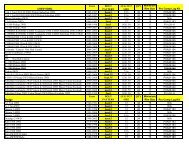
PART# DESCRIPTION QUANTITY ILLUSTRATION#<br />
90-1146 Lower A-Arm Front Drop Bracket 2 12<br />
90-1151 Lower A-Arm Rear Drop Bracket 2 10<br />
90-1142 (Pass.) Diff. Drop Bracket 1 9<br />
90-1117 (Drvr.) Diff. Drop Bracket 1 8<br />
90-2069 Torque Tube 1 8<br />
90-6076 Hardware Pack Containing:<br />
70-0501501500 1/2” x 1 1/2” USS Gd. 5 Hex Bolt 2 12<br />
70-0621501501 5/8” x 1 1/2”USS Gr. 5 Hex Bolt 4 10<br />
70-0624501500 5/8” x 4 1/2” USS Gd. 5 Hex Bolt 2 12<br />
70-0625501500 5/8” x 5 1/2” USS Gr. 5 Hex Bolt 4 10<br />
70-0625001500 5/8” x 5” USS Gd. 5 Hex Bolt 2 12<br />
72-05000100512 1/2” USS Nyloc Nut 2 12<br />
72-06200100512 5/8”USS Nyloc Nut 12 10,12<br />
73-05000030 1/2” SAE Flat Washer 4 12<br />
73-0600030 5/8” SAE Flat Washer 24 10,12<br />
73-06200032 5/8” USS Flat Washer 4 10<br />
90-6077 Hardware Pack Containing:<br />
70-0431251500 7/16” x 1 1/4” USS Gd. 5 Hex Bolt 1 8<br />
70-0564001500 9/16” x 4” USS Gd. 5 Hex Bolt 1 8<br />
72-04300100512 7/16” USS Nyloc Nut 1 8<br />
72-05600100512 9/16” USS Nyloc Nut 1 8<br />
73-04300030 7/16” SAE Flat Washer 2 8<br />
73-05600030 9/16” SAE Flat Washer 2 8<br />
90-6081 Hardware Pack Containing:<br />
15-11018 Bumpstop - Low <strong>Pro</strong>file - Hex 2 12<br />
15-11031 Cone Bumpstop - Short Shaft 2 10<br />
15-11148 Bushing - Differential Mount 12 9<br />
15-11304 Bushing-Pivot Sleeve 2 6,7<br />
72-03700100512 3/8” USS Gd. 5 Nyloc Nut 4 10,12<br />
90-2085 Pivot Sleeve 2 6,7<br />
90-2108 Sleeve-GM (Pass.) Differential Drop 2 9<br />
90-2109 Sleeve-GM <strong>Comp</strong>ression Strut 4 13<br />
90-2110 Sleeve-Crossmember Anti-Crush 2 13<br />
90-6084 Hardware Pack Containing:<br />
7225 AB Brakeline-Front GM IFS w/Crush Washer 2<br />
90-6029 Hardware Pack-Brakeline Support Kit 1<br />
90-6085 Hardware Pack Containing:<br />
45558 Straight 5/8” Black Bushing 4<br />
600040-1 Cut 5/8” Black “T” Bushing 4
Box 2 of 5 PN <strong>51098</strong>-2<br />
13-90347 5/8” U-Bolt, Square 4 16<br />
90-1155 Upper A-Arm Drop Bracket (Drvr.) 1 11<br />
90-1162 Upper A-Arm Drop Bracket (Pass.) 1 11<br />
96-1313 Diff. Mount Cover Plate 1 3<br />
90-4011 Torsion Bar Drop 2 14<br />
95-400 4” Lift Block 2 16<br />
20-65471 Hardware Pack Containing:<br />
13-10423 High Nut, 5/8” - 18 8 16<br />
13-30330 Flat Washer, 5/8” 8 16<br />
90-6078 Hardware Pack Containing:<br />
70-0505501500 1/2” x 5 1/2” USS Gd. 5 Hex Bolt 6 11<br />
72-05000100512 1/2” USS Nyloc Nut 6 11<br />
73-05000030 1/2” SAE Flat Washer 12 11<br />
90-6080 Hardware Pack Containing:<br />
70-0375001500 3/8” x 5” USS Gd. 5 Hex Bolt 2 14<br />
70-0504001500 1/2” x 4” USS Gd. 5 Hex Bolt 4 14<br />
72-03700100512 3/8” USS Nyloc Nut 2 14<br />
72-05000100512 1/2” USS Nyloc Nut 4 14<br />
73-03700030 3/8” SAE Flat Washer 4 14<br />
73-05000030 1/2” SAE Flat Washer 8 14<br />
90-6082 Cam Bolt Hardware Pack<br />
13-90386 Cambolt Assembly-GM IFS 4 11<br />
90-6083 Hardware Pack Containing:<br />
90-2111 Sleeve w/ Washer 2 11<br />
90-2112 Sleeve-.750”x.50”x3.94” 2 11<br />
90-2113 Sleeve-.750”x.50”x3.44” 2 11<br />
90-1215 Load Washer-Flat Side-2.0” O.D.x.550” ID. 6 11<br />
90-1216 Load Washer-1.50” O.D. x .532” I.D. 2 11<br />
3<br />
<strong>51098</strong><br />
Revised<br />
12.1.2005<br />
PART# DESCRIPTION QUANTITY ILLUSTRATION#<br />
Box 3 of 5 PN <strong>51098</strong>-3<br />
90-1104 Strut Mount 2 13<br />
90-1163 Front Upper Crossmember 1 12<br />
90-1164 Front Lower Crossmember 1 12<br />
90-1168 Center Steering Link 1 7<br />
90-1141 Rear Crossmember w/Differential Mount 1 10<br />
90-2074 Lateral <strong>Comp</strong>ression Strut 2 13<br />
90-1133 Steering Link Arm (Long) 1 6,7<br />
90-1171 Steering Link Arm (Short) 1 6,7<br />
90-1173 Idler Arm Spacer (3 hole) 1 5<br />
90-6075 Hardware Pack Containing:<br />
70-0502251500 1/2” x 2 1/4” USS Gd. 5 Hex Bolt 1 6<br />
70-0503001500 1/2” x 3” USS Gd. 5 Hex Bolt 3 5<br />
70-0503251500 1/2” x 3 1/4” USS Gd. 5 Hex Bolt 1 7<br />
73-05000030 1/2” SAE Flat Washer 10 5,6,7<br />
72-05000100512 1/2” USS Nyloc Nut 5 5,6,7
4<br />
<strong>51098</strong><br />
Revised<br />
12.1.2005<br />
PART# DESCRIPTION QUANTITY ILLUSTRATION#<br />
90-6079 Hardware Pack Containing:<br />
73-05000030 1/2” SAE Flat Washer 12 13<br />
72-05000100512 1/2” USS Nyloc Nut 6 13<br />
70-0503001500 1/2” x 3” USS Gd. 5 Hex Bolt 2 13<br />
70-0504001500 1/2” x 4” USS Gd. 5 Hex Bolt 4 13<br />
Box 4 of 5 PN <strong>51098</strong>-4<br />
324501 ES3000 Shock Absorbers 2<br />
329500 ES3000 Shock Absorbers 2<br />
90-4050 246 1/2 <strong>Ton</strong> Front Driveshaft 1<br />
90-6058 Hardware Pack Containing:<br />
70-0311502800 5/16” x 1 1/2” SAE Gr. 8 Hex Bolt 4 TC1-3<br />
70-0501252803 1/2” x 1 1/4” SAE Gr. 8 Allen Bolt 1 TC1-3<br />
72-0752546 3/4” SAE Half Nut (Jam) 1 TC1-3<br />
73-03100536 5/16” Split Lock Washer 4 TC1-3<br />
73-07500834 3/4” SAE Hardened Flat Washer 1 TC1-3<br />
73-112514044 1.125” x 1.40 O-Ring 1 TC1-3<br />
90-4005 NP-246 Shaft 1 TC1-3<br />
90-4006 NP-246 Shaft Cap 1 TC1-3<br />
90-4015 Spicer 1310 CV Yoke 1 TC1-3<br />
90-4016 NP246 Cap Spacer 1 TC1-3<br />
73-06200032 5/8” USS Flat Washer 4 TC1-3<br />
13124<br />
Box 5 of 5 PN <strong>51098</strong>-5<br />
Add-A-Leaf Kit 1 15
Introduction:<br />
♦ This installation requires a professional mechanic!<br />
♦ We recommend that you have access to a factory service manual for your vehicle to assist in the<br />
disassembly and reassembly of your vehicle. It contains a wealth of detailed information.<br />
♦ Prior to installation, carefully inspect the vehicle’s steering and driveline systems paying close<br />
attention to the tie rod ends, ball joints, wheel bearing preload, pitman and idler arm. Additionally,<br />
check steering-to-frame and suspension-to-frame attaching points for stress cracks. The overall<br />
vehicle must be in excellent working condition. Repair or replace all worn or damaged parts!<br />
♦ Read the instructions carefully and study the illustrations before attempting installation! The more<br />
familiar you are with the procedures, the easier and quicker your installation will be.<br />
♦ Check the parts and hardware against the parts list to assure that your kit is complete. Separating<br />
parts according to the areas where they will be used and placing the hardware with the brackets<br />
before you begin will save installation time.<br />
♦ Secure and properly block vehicle prior to beginning installation.<br />
♦ ALWAYS wear safety glasses when using power tools or working under the vehicle!<br />
5<br />
<strong>51098</strong><br />
Revised<br />
12.1.2005<br />
♦ Use caution when cutting is required under the vehicle. The factory undercoating is flammable. Take<br />
appropriate precautions. Have a fire extinguisher close at hand.<br />
♦ Foot pound torque readings are listed on the Torque Specifications chart at the end of the<br />
instructions. These are to be used unless specifically directed otherwise.<br />
Please Note:<br />
♦ Front end realignment will be necessary.<br />
♦ Speedometer and ABS recalibration are necessary if larger tires (10% more than stock diameter) are<br />
installed.<br />
♦ This system utilizes the stock torsion bars which normally afford the best ride quality. If, after the kit is<br />
installed, ride or handling seems too “soft”, heavier Gross Vehicle Weight Rating (GVWR) bars can be<br />
installed. GM offers various bars up to 10,500 lbs. GVWR.<br />
♦ Tire and wheel choice is crucial in assuring proper fit, performance and safety of your <strong>Pro</strong> <strong>Comp</strong><br />
equipped vehicle. For this application a wheel not exceeding 8” in width, with a backspacing of 3.5”<br />
must be used. Diameter of wheel may be any of the following 3 choices, 15”, 16”, 17”. Any other<br />
diameter, either smaller or larger, will not be endorsed as acceptable by <strong>Pro</strong> <strong>Comp</strong> Suspension and<br />
will void any and all warranties, written or implied. In addition, a quality tire of radial design, with a<br />
maximum height of 33” and a maximum width 12.50” is recommended. Use of a 35” x 12.50” tire will<br />
require fender modification.<br />
♦ Purchase of a new PRO COMP drive shaft may be necessary to eliminate driveline vibration.
6<br />
<strong>51098</strong><br />
Revised<br />
12.1.2005<br />
• WARNING: Be extremely careful when loading or unloading the torsion bars! There is a<br />
tremendous amount of stored energy in the bars. Keep your hands and body clear of the<br />
adjuster arm assembly and puller tool in case anything slips or breaks! Remember your safety<br />
glasses!<br />
• While we have listed the hardware that is to be kept and that to be discarded, it would be wise to keep<br />
all hardware until the installation is complete.<br />
Note: A special puller tool is required for safe removal and installation of the torsion adjuster<br />
arms. This special puller can be purchased from you local GM dealer (Tool #J36202) or from<br />
Kent Moore Tool Group in Roseville, MI. (800) 345-2233 or (313) 774-9500 (<strong>Part</strong> #J22517-C).<br />
You may be able to rent one of these tools at your local parts store. Refer to the GM service<br />
manual for more information.<br />
Front Disassembly:<br />
1) Put vehicle in neutral. Place floor jack under the lower control arm’s front crossmember and raise<br />
vehicle. Place jack stands under the frame rails behind the front wheel wells and lower the frame onto<br />
the stands. Put vehicle in park, set emergency brake and block rear wheels, in front of and behind tires.<br />
Remove front wheels.<br />
NOTE: A special puller tool is required for safe removal/installation of the torsion bar<br />
adjustment arms. This special puller can be purchased from your GM dealer. (Tool# J36202) or<br />
from Kent Moor Tool Group, Roseville, MI (800) 345-2233 or (313) 774-9500 (<strong>Part</strong># J-22517-c).<br />
WARNING: Be extremely careful when loading or unloading the torsion bars. There is a<br />
tremendous amount of stored energy in the bars. Keep your hands and body clear of the adjuster<br />
arm assembly and puller tool in case anything slips or breaks.<br />
2) Measure and record torsion bar adjusting screw depth for<br />
replacement of torsion adjuster arm. Remove the torsion bar<br />
adjusting screw. Apply a small amount of lubricating grease<br />
to the puller threads and the puller shaft-to adjuster arm<br />
contact point. Position the puller and load adjuster arm until<br />
the adjuster nut can be removed from the crossmember. See<br />
ILLUSTRATION 1. With the bar unloaded, slide it further<br />
forward into the lower control arm. If the bar seems lodged,<br />
use a hammer and punch through the hole in back of the<br />
crossmember. When the bar shifts forward, the adjuster arm<br />
can be removed.<br />
3) Remove torsion bar crossmember by removing the 3 bolts<br />
per rail that connect it to the frame. It may be necessary to<br />
ILLUSTRATION 1<br />
A. Nut<br />
182<br />
B. Torsion Bar<br />
Adjusting Bolt<br />
C. Apply Lubricant at<br />
Points to Ease Installation<br />
182. Torsion Bar<br />
A<br />
C B<br />
J 36202
Idler Arm<br />
Frame Bolts<br />
Tie Rod<br />
Outer Ball<br />
Joint Nut<br />
Idler Arm<br />
Mounting<br />
Bracket<br />
Idler Arm Frame Nut<br />
Knuckle<br />
Tie Rod Ball Stud<br />
Tie Rod Inner Ball Joint<br />
Idler Arm Ball Joint<br />
Idler Arm Ball<br />
Joint Nut<br />
Relay Rod<br />
jack up the exhaust to allow clearance for<br />
crossmember removal. With the crossmember out of<br />
the way, the torsion bars can be dislodged from the<br />
lower control arms and removed. Mark and separate<br />
the bars, since they must be reinstalled on the same<br />
side and direction they were removed from.<br />
NOTE: Steps 4 through 8 are performed one<br />
side at a time:<br />
4) At driver side front, locate the rubber brake hose<br />
that runs from caliper to frame. Pinch it closed with<br />
vise grips or a small “c” clamp and detach it from the<br />
caliper. Plug or cover the caliper opening to prevent<br />
contamination.<br />
Steering Gear<br />
Tie Rod Inner Ball Joint Nut<br />
7<br />
Frame<br />
Tie Rod Inner Ball Joint Nut<br />
Pitman Arm Nut<br />
ILLUSTRATION 3<br />
Clamp Nut Adjuster Tube<br />
CUT OFF FLUSH<br />
Adjuster Tube<br />
<strong>51098</strong><br />
Revised<br />
12.1.2005<br />
ILLUSTRATION 2<br />
Tie Rod<br />
Outer Ball<br />
Joint Nut<br />
REAR LOWER DIFFERENTIAL MOUNT<br />
(DRIVER SIDE)<br />
NOTE: If your vehicle is equipped with an ABS Brake System, disconnect the sensor wire and<br />
Pitman<br />
Arm Ball<br />
Stud<br />
Knuckle<br />
Tie Rod<br />
Ball Stud
eposition so not to damage ends.<br />
5) Remove the 6 bolts that attach CV axle to the<br />
differential.<br />
6) Detach inner end of tie rod from relay rod/<br />
centerlink as shown in ILLUSTRATION 2.<br />
7) Remove both anti-sway bar drop links, which<br />
connect bar body to lower control arms. The link<br />
nuts, accessed through the bottom of the arms,<br />
are somewhat restricted. It may be necessary to<br />
detach the bar at the frame.<br />
8) Place a floor jack under the hub assembly.<br />
Remove upper and lower control arm bolts and lower assembly to floor.<br />
Repeat steps 4 thru 8 on passenger side.<br />
9) Detach the driveshaft at the differential and secure it out of the way.<br />
10) Remove the differential skid plate, if vehicle is so equipped.<br />
11) Unplug the differential’s electronic coupler and vent hose.<br />
8<br />
<strong>51098</strong><br />
Revised<br />
12.1.2005<br />
12) Remove the bolt that attached the rear of the differential to lower control arm/differential mount. Using<br />
a hack saw or suitable cutting tool, cut off the driver side rear wrap around differential bracket as shown<br />
in ILLUSTRATION 3. This allows differential to drop straight down.<br />
13) Position a floor jack under the differential and remove the 3 remaining bolts:<br />
1 bolt - differential to driven frame<br />
2 bolt - passenger side axle tube to frame<br />
Now lower the assembly to the floor.<br />
FRAME<br />
ILLUSTRATION 4<br />
NOTE:<br />
GRIND<br />
FLUSH WITH<br />
FRAME<br />
STEEL FRAME<br />
BRACKET<br />
STOCK RUBBER<br />
TRAVEL STOP
14) On both sides of the frame near upper<br />
control arm mounts, unbolt the stock<br />
rubber compression travel stops from their<br />
steel frame mount brackets and discard.<br />
With a torch, carefully trim the steel frame<br />
mount brackets from the frame as shown<br />
in ILLUSTRATION 4. CAUTION:<br />
UNDERCOATING IS FLAMMABLE.<br />
Grind clean all cutting slag from the<br />
trimming performed in previous steps.<br />
Paint and undercoat exposed metal.<br />
15) Referring back to ILLUSTRATION 2<br />
detach the relay rod/centerlink from the<br />
pitman and idler arm studs.<br />
16) Detach the anti-sway bar from the<br />
frame. Reinstall, reverse or flipped over<br />
from its original position.<br />
17) Install idler arm spacer bracket between the Idler arm and its<br />
frame mounting point. The arm is<br />
accessed by removing the passenger<br />
ILLUSTRATION 6<br />
side inner fender. Install with suppled<br />
bolts, washers and nuts, use bracket (90-<br />
1173) and refer to ILLUSTRATION 5. It<br />
may be necessary to enlarge holes in idler<br />
arm base to 1/2”.<br />
STEERING<br />
LINK ARM<br />
90-1133 OR<br />
90-1171<br />
18) Install steering link arm (90-1133 or 90-<br />
1171) to existing front crossmember hole<br />
using the hex bolt (1/2” x 2-3/4”), flat<br />
washer, pivot sleeve (90-2085), bushing<br />
(15-11304) and nyloc nut as shown in<br />
ILLUSTRATION 6. Torque 1/2” nut to 75<br />
ft./lbs.<br />
NOTE: Very Important set-up<br />
procedure.<br />
HEX BOLT,<br />
1/2” x 3”<br />
LG.<br />
EXISTING<br />
FRONT<br />
CROSSMEMBER<br />
9<br />
FLAT WASHER,<br />
1/2”<br />
IDLER ARM<br />
SPACER<br />
90-1173<br />
<strong>51098</strong><br />
Revised<br />
12.1.2005<br />
ILLUSTRATION 5<br />
FLAT WASHER, 1/2”<br />
FRAME<br />
STOCK IDLER ARM<br />
NYLOC<br />
NUT,<br />
1/2” - 13<br />
NYLOC NUT, 1/2”-13<br />
FLAT WASHER, 1/2”<br />
BUSHING, 15-11304<br />
PIVOT SLEEVE,<br />
90-2085<br />
FLAT<br />
WASHER, 1/2”<br />
HEX BOLT, 1/2”<br />
X 2 3/4” LG.
DIFFEREN-<br />
TIAL DROP<br />
BRACKET<br />
DRIVER<br />
SIDE 90-1117<br />
HEX<br />
BOLT,<br />
9/16” X<br />
4” LG.<br />
ILLUSTRATION 7<br />
CENTER<br />
STEER-<br />
ING LINK<br />
90-1168<br />
EXISTING<br />
PITMAN ARM<br />
FLAT WASHER, 1/2”<br />
FLAT<br />
WASHER,<br />
9/16”<br />
DIFFERENTIAL<br />
FLAT WASHER, 9/16”<br />
TIE<br />
ROD<br />
STABILIZER MOUNT<br />
(IF APPLICABLE)<br />
PIVOT<br />
SLEEVE,<br />
90-2085<br />
HEX BOLT, 1/2” x 3-1/4” LG.<br />
EXISTING<br />
FRAME<br />
EXISTING<br />
NYLOC NUT, 9/16”-12<br />
10<br />
IDLER ARM<br />
TORQUE<br />
TUBE<br />
90-2069<br />
TIE ROD<br />
NYLOC NUT,<br />
1/2”-13<br />
FLAT<br />
WASHER, 1/2”<br />
BUSHING,<br />
15-11304<br />
STEERING<br />
LINK ARM<br />
90-1171 or<br />
901133<br />
NYLOC NUT, 7/16”-14<br />
FLAT WASHER, 7/16”<br />
<strong>51098</strong><br />
Revised<br />
12.1.2005<br />
ILLUSTRATION 8<br />
UPPER REAR<br />
A-ARM<br />
MOUNT<br />
FLAT WASHER, 7/16”
19) Next install center steering link (90-1168) to<br />
pitman arm and idler arm. Torque nuts to 48 ft./<br />
lbs. Install bushing and pivot sleeve into<br />
steering link arm. Position steering link arm<br />
over the tube boss on steering link. The hole in<br />
the arm should align with the hole in the<br />
steering link and the bolt should install with<br />
ease. 1/8” misalignment is acceptable if the<br />
steering link can be moved by hand to perfect<br />
alignment. Remove bolt and turn steering<br />
wheel to a full right turn. The holes in the<br />
steering link and link arm should align at this<br />
point. Repeat this step at a full left turn and<br />
check hole alignment again. The 1/2” bolt that<br />
secures the steering link arm to the steering link<br />
should be in nonbinding state through the full<br />
steering cycle to eliminate undue stress and<br />
fatigue on the steering components. Call PRO<br />
COMP at (800) 776-0767, if proper alignment of<br />
steering components cannot be achieved.<br />
ILLUSTRATION 9<br />
20) Attach the steering link arm to the center steering link as shown in ILLUSTRATION 7. Torque 1/2”<br />
nut to 75 ft./lbs.<br />
11<br />
BUSHING,<br />
15-11148<br />
FRAME<br />
EXISTING<br />
BUSHING<br />
15-11148<br />
DIFFERENTIAL<br />
<strong>51098</strong><br />
Revised<br />
12.1.2005<br />
21) Attach the driver side front differential drop bracket (90-1117) to the stock mounting bracket with the<br />
existing hardware; Finger tighten. See ILLUSTRATION 8.<br />
22) Attach the passenger side front differential drop bracket (90-1142) to the frame bracket with the<br />
existing hardware. See ILLUSTRATION 9.<br />
EXISTING<br />
SLEEVE<br />
90-2108<br />
FRONT DIFFERENTIAL<br />
DROP BRACKET, 90-1142<br />
23) Raise the differential into position with a floor jack. Attach the driverside front differential drop bracket<br />
(90-1117) to the top of the differential with the 9/16” hardware provided. See ILLUSTRATION 8.<br />
*NOTE: The clearance between the upper differential mount 90-1117 and the web of the center<br />
link is very critical and may need to be increased by grinding the aluminum housing in the area<br />
that contacts the web of the centerlink. Bending the edge of the centerlink web away from the<br />
aluminum case may also be required. This can be done by using a crescent wrench to twist the<br />
web away from the differential housing.<br />
NOTE: On some models the differential case will have to be ground down to provide adequate
ILLUSTRATION 10<br />
FLAT<br />
WASHER, 5/8”<br />
HEX<br />
BOLT,<br />
5/8” x 5-<br />
1/2” LG.<br />
BUMPSTOP,<br />
15-11031<br />
EXISTING<br />
INSTALL 5/8”<br />
USS WASHERS<br />
BOTH SIDES<br />
FLAT<br />
WASHER, 5/8”<br />
EXISTING<br />
BOLT<br />
FLAT WASHER, 5/8”<br />
HEX BOLT, 5/8” x 5-1/2” LG.<br />
HEX BOLT,<br />
5/8” x 1 1/2”<br />
FLAT<br />
WASHER,<br />
5/8”<br />
FLAT<br />
WASHER,<br />
5/8”<br />
NYLOC NUT, 5/8”-11<br />
12<br />
FLAT<br />
WASHER, 5/8”<br />
REAR CROSSMEMBER<br />
90-1141<br />
<strong>51098</strong><br />
Revised<br />
12.1.2005<br />
LOWER A-<br />
ARM REAR<br />
DROP<br />
BRACKET<br />
90-1151<br />
LOWER<br />
CONTROL<br />
ARM<br />
DIFFEREN-<br />
TIAL<br />
MOUNT<br />
EXISTING<br />
BOLT<br />
NYLOC<br />
NUT,<br />
5/8”-11<br />
clearance between case and differential mount, or the optional weld in cover plate (96-1313) can<br />
be installed.<br />
NOTE: It is very important that the differential is centered in the chassis. The best way to<br />
accomplish this is to measure the distance from the C.V. flange on the differential to the rear<br />
lower control arm mounting hole. <strong>Comp</strong>are driver side to passenger side and move differential to<br />
center. On some models the cast ribs on the differential case will need to be ground away to<br />
provide adequate clearance between case and differential mount.<br />
• Failure to center the differential may cause premature Constant Velocity (C.V.) joint wear or failure.<br />
24) Using the 7/16” x 1-1/4” hex bolt, flat washer and nyloc nut provided, install one end of the torque<br />
FLAT<br />
WASHER<br />
, 5/8”<br />
NYLOC<br />
NUT,<br />
5/8”-11
ILLUSTRATION 11<br />
NYLOC NUT, 1/2”-13<br />
FLAT<br />
WASHER,<br />
1/2”<br />
FRAME<br />
LOAD WASHER, 90-1215<br />
SLEEVE, 90-2113<br />
SHIM WASHER, 90-1216<br />
“AS NECESSARY”<br />
CAM BOLT<br />
13-90386<br />
FLAT WASHER, 1/2”<br />
EXISTING<br />
HEX BOLT,<br />
1/2” x 5-1/2”<br />
13<br />
SLEEVE,<br />
90-2112 (3.94” LG.)<br />
UPPER A-ARM DROP<br />
BRACKET 90-1155<br />
CAM<br />
BOLT<br />
13-90386<br />
<strong>51098</strong><br />
Revised<br />
12.1.2005<br />
SLEEVE W/<br />
WASHER<br />
90-2111 (3.94”<br />
LG.)<br />
FLAT<br />
WASHER,<br />
1/2”<br />
tube (90-2069) to the existing upper rear a-arm mount. Install the other end to the driverside differential<br />
drop bracket as shown in ILLUSTRATION 8.<br />
25) Attach the two lower a-arm rear drop brackets (90-1151) to frame using existing bolts in upper hole on<br />
bracket as shown in ILLUSTRATION 10. Be sure the bolts are placed with heads inward toward the axle<br />
and threaded end away from axle to allow extra clearance for inner CV joint.<br />
26) Install the rear crossmember with differential mounting bracket (90-1141) as shown in<br />
ILLUSTRATION 10. (A 5/8” USS flat washer must be install on back side of the lower a-arm drop<br />
between the drop and the lower crossmember. This will assist in moving the differential as far back as<br />
possible). Install differential mount bolt in lower crossmember.<br />
27) Install the driver side upper a-arm drop bracket (90-1155) into the stock a-arm location points and<br />
onto the frame. Reference ILLUSTRATION 11 and note the following:<br />
a) Temporarily bolt (or hold tightly) the new upper a-arm drop bracket in place. Use an angle indicator to<br />
HEX<br />
BOLT,<br />
1/2” X<br />
5-1/2”
ILLUSTRATION 12<br />
TRUCK FRONT<br />
CROSSMEMBER<br />
HEX<br />
BOLT,<br />
5/8” x 4<br />
1/2” LG.<br />
BUMP-<br />
STOP,<br />
15-11018<br />
FRONT UPPER<br />
CROSSMEMBER<br />
90-1163<br />
FRONT LOWER A-ARM<br />
HEX BOLT, 1/2” x<br />
1-1/2” LG.<br />
NYLOC NUT, 5/8”-11<br />
FLAT<br />
WASHER, 5/8<br />
NYLOC NUT, 5/8”-11<br />
FLAT WASHER, 5/8”<br />
FRONT LOWER CROSS-<br />
MEMBER 90-1141<br />
14<br />
FRONT OF VEHICLE<br />
LOAD WASHER,<br />
20-830463<br />
FLAT<br />
WASHER, 5/8”<br />
<strong>51098</strong><br />
Revised<br />
12.1.2005<br />
insure the bracket sits parallel (90 Deg.) to the frame rail. If it does not fit, grind a little more where the<br />
bumpstop was cut off. (It is important to have the vehicle sitting level side-to-side on jackstands before<br />
starting this project).<br />
b) Once positioned, use the upper a-arm drop bracket as a guide to drill the necessary holes in the<br />
frame.<br />
LOWER A-<br />
ARM FRONT<br />
DROP<br />
BRACKET<br />
90-1146<br />
FLAT WASHER, 5/8”<br />
HEX<br />
BOLT,<br />
5/8” x 5<br />
1/2”<br />
c) Enlarge the two holes in the outer face only of the frame to 3/4” so that the anti-crush sleeves (90-<br />
2112 and 90-2113) can be inserted into them. The holes on the backside are only large enough for the<br />
bolts to protrude, not the sleeves. The sleeves are trapped between the inner frame wall and the drop<br />
bracket. The sleeves prevent the frame from crushing when the bracket’s bolts are torqued to<br />
specifications during final assembly.<br />
EXISTING<br />
HEX BOLT,<br />
5/8” x 5” LG.<br />
FLAT<br />
WASHER<br />
, 5/8”<br />
NYLOC<br />
NUT,<br />
5/8”-11
ILLUSTRATION 13<br />
HEX BOLT,<br />
1/2” x 4” LG.<br />
NYLOC NUT, 1/2”-13<br />
EXISTING TRUCK<br />
CROSSMEMBER<br />
NYLOC<br />
NUT, 1/2”-<br />
13<br />
FLAT WASHER,<br />
1/2”<br />
LATERAL COMPRESSION<br />
STRUT 90-2074<br />
15<br />
<strong>51098</strong><br />
Revised<br />
12.1.2005<br />
NOTE: The pre-existing holes in the frame may not line up with the holes in the <strong>Pro</strong> <strong>Comp</strong><br />
bracket. You must enlarge holes in frame to match <strong>Pro</strong> <strong>Comp</strong> bracket. Do not drill holes in <strong>Pro</strong><br />
<strong>Comp</strong> bracket.<br />
NOTE: If you are installing a <strong>Pro</strong> <strong>Comp</strong> shock hoop, install it at this time.<br />
d) Install the upper a-arm drop bracket into the original bracket slots using the hardware provided as<br />
outlined in ILLUSTRATION12.<br />
NOTE: If the bracket does not sit flush at it’s 3 mounting points when tightened it will crack<br />
the bracket at welds overtime. Use load washer 90-1216 as needed in Illustration 11.<br />
Repeat Step 27 on the Passenger side.<br />
FLAT WASHER, 1/2”<br />
SLEEVE, 90-2110<br />
STRUT<br />
MOUNT<br />
90-1104<br />
HEX BOLT,<br />
1/2” x 3” LG.<br />
EXISTING REAR<br />
CROSSMEMBER W/<br />
DIFFERENTIAL<br />
MOUNT<br />
FLAT<br />
WASHER,<br />
1/2”<br />
SLEEVE<br />
90-2109<br />
(2.75” LG.)<br />
HEX BOLT,<br />
1/2” x 4” LG.<br />
BUSHING,<br />
15-11148
28) Install bump stop (15-11018) onto<br />
lower a-arm front drop bracket (90-<br />
1146) as shown in ILLUSTRATION<br />
12. Install 90-1146 into factory<br />
mount, use existing bolts and nuts.<br />
29) Bolt the front upper crossmember<br />
(90-1163) to the frame using the<br />
1/2” x 1-1/2” bolts, washers and<br />
nuts as shown in ILLUSTRATION<br />
12.<br />
NOTE: Due to inconsistency of<br />
factory crossmember, washers<br />
may be required between existing<br />
and <strong>Pro</strong> <strong>Comp</strong> upper<br />
crossmembers for proper fitment.<br />
30) Attach the front lower<br />
crossmember (90-1164) to the lower<br />
inside holes of the lower a-arm front<br />
NYLOC<br />
NUT,<br />
1/2”-13<br />
FLAT<br />
WASHER,<br />
1/2”<br />
FLAT<br />
WASHER,<br />
1/2”<br />
HEX<br />
BOLT,<br />
1/2” x 4”<br />
LG.<br />
FLAT WASHER, 3/8”<br />
HEX BOLT,<br />
3/8” x 5” LG.<br />
drop brackets (90-1146) using the 5/8” x 5-1/2” hex bolts provided See Torque Specification Chart at<br />
end of instructions.<br />
16<br />
NYLOC NUT, 3/8”-16<br />
<strong>51098</strong><br />
Revised<br />
12.1.2005<br />
31) Rehang control arms. Start at the driverside. Both sides install identically. Raise the control arm<br />
assembly into position with a floor jack. Install with 5/8” hardware at the lower control arm attaching<br />
point. Use 5/8” bolts facing forward on front leg and facing rearward leg as shown in ILLUSTRATION 12.<br />
Now attach upper control arm to brackets per ILLUSTRATION 11. Be sure that the anti-sway bar body is<br />
pivoted down so it is below the upper control arm’s front leg.<br />
Install new eccentric cam bolt kit (90-6082) and adjust bolts to a neutral, or centered position (torque to<br />
75-90 ft./lbs.)<br />
32) Attach CV axle flange to differential. Use loctite and torque to 60-ft./lbs.<br />
ILLUSTRATION 14<br />
FLAT WASHER, 3/8”<br />
NYLOC NUT,<br />
1/2”-13<br />
FLAT WASHER,<br />
1/2”<br />
TORSION BAR<br />
DROP BRACKET<br />
90-4011<br />
TORSION BAR<br />
CROSSMEMBER<br />
FLAT<br />
WASHER,<br />
1/2”<br />
HEX BOLT,<br />
1/2” x 4” LG.<br />
33) <strong>Pro</strong> <strong>Comp</strong>’s kit incorporates two traction bar-like rods called lateral compression struts (90-2074) that<br />
bolt to the rear a-arm crossmember and extend to the next chassis crossmember. See ILLUSTRATION
13. These eliminate for/aft movement of the front differential.<br />
NOTE: Sleeve (90-2110) fits inside the crossmember, preventing the frame from crushing<br />
when the bolts are torqued to specifications.<br />
17<br />
<strong>51098</strong><br />
Revised<br />
12.1.2005<br />
34) Install the new steel brake hose (7225-AB). Thoroughly clean all mating surfaces. Make sure old<br />
crush washers are removed. Attach the new grommet to the upper control arm mount with the hardware<br />
provided.<br />
NOTE: Reinstall and properly route ABS wiring on vehicles with this option.<br />
Position hoses so they don’t make contact with any other parts. Hoses must be able to slide<br />
unrestricted through the grommets.<br />
NOTE: Do not attach brake lines to shocks.<br />
35) Install the front shock absorbers (324501). Torque upper and lower bolts to 48 ft./lbs. Cycle<br />
suspension through the full travel cycle and check for adequate clearance between shocks, bumpstops<br />
and brake hoses. Brake hose should be routed behind shocks. Make sure brake lines are clean and dry<br />
of any material before ABS brake bleeding.<br />
NOTE: Hardware kit part #90-6085 must be installed on 97 and later vehicles. Shocks must be<br />
run upside down to prevent shock canister from hitting upper control arm.<br />
36) Reinstall the differential vent hose. Reconnect the electrical plug.<br />
37) Install the front anti-sway bar drop links. Both sides install identically. Tighten drop link bolt just until<br />
bushings swell slightly.<br />
RECHECK CLEARANCES:<br />
38) With vehicle still on jack stands and suspension hanging at full extension travel, cycle steering lock to<br />
lock to check all components for proper operation and clearance. Tighten to required torque<br />
specifications per chart at end of instructions.<br />
39) Thoroughly bleed air from brake system.
40) Insert torsion bars into the lower control arms. The bar’s rear facing ends are now hanging. This<br />
step is a two man operation. Balance the crossmember on a floor jack and raise it to mate with the<br />
hanging bar ends. Now locate the adjuster arms inside the crossmember and onto the bar ends.<br />
18<br />
<strong>51098</strong><br />
Revised<br />
12.1.2005<br />
41) After the torsion bar crossmember is removed and its brackets are flipped so they mount under the<br />
frame, install the new aluminum torsion bar drop brackets (90-4011) as shown in ILLUSTRATION 14.<br />
Torsion bars are marked “left” and “right” and the torsion bar adjusting bolt’s exposed length is measured<br />
before removal. This way they can be reinstalled to the stock position.<br />
42) Load the torsion bars reversing the sequence of ILLUSTRATION 2, again being very careful. Tighten<br />
until arms are just clearing nut blocks.<br />
TRANSFER CASE MODIFICATION INSTRUCTIONS:<br />
Tool <strong>Part</strong> # snap on SRP-4 is required to proceed. (Snap ring tool).<br />
1) Remove drain plug from transfer case and drain oil. Replace drain plug and tighten.<br />
2) Remove front and rear driveshafts.<br />
3) Unplug the wiring harness from the transfer case.<br />
4) Loosen the nuts that attach the transfer case to the adapter. Support transfer case with a<br />
transmission jack. Remove nuts from studs and lower<br />
transfer case.<br />
ILLUSTRATION TC 2A<br />
ILLUSTRATION TC 1<br />
SPEED<br />
SENSORS<br />
Rubber<br />
Plug
ILLUSTRATION TC 2B<br />
MARK<br />
LOCATION<br />
OF BOLTS<br />
AND STUDS<br />
19<br />
<strong>51098</strong><br />
Revised<br />
12.1.2005<br />
5) Mark location of wire harness and the plastic speed sensors. Unplug wire and remove sensors. Be<br />
sure to mark location so as to replace sensors in original location. See ILLUSTRATION TC 1.<br />
6) Remove bolts on rear side of transfer case to separate the case halves. Remove rubber plug on rear<br />
out put housing this will allow access to snap ring. See ILLUSTRATION TC 2A & TC 2B.<br />
7) With the bolts removed open snap ring and separate case halves. Set back case half aside.<br />
ILLUSTRATION TC3.<br />
8) Using a long drift punch remove the plug inside the front drive shaft splined hole. Insert punch from<br />
the front of the splined tube. The plug will come out the rear of the tube.<br />
9) Clear any debris from the splined bore.<br />
10) Install part #90-4006 cap into splined bore from the<br />
rear without the o-ring. The cap should be flush with the<br />
rear of the tube, when it bottoms against the internal<br />
spline. Depending on manufacture date of the transfer<br />
case (see ILLUSTRATION TC4B) and depth of spline,<br />
one of the two cap assembles will be used. Once the<br />
proper assembly is determined remove and install o-ring<br />
into groove.<br />
ILLUSTRATION TC3<br />
ILLUSTRATION TC4A<br />
90-4006 WHEN<br />
INSTALLED<br />
MUST BE<br />
FLUSH WITH<br />
THIS TUBE.
20<br />
<strong>51098</strong><br />
Revised<br />
12.1.2005<br />
11) Insert 90-4005 shaft from front of splined hole. It may be necessary to tap shaft with a plastic hammer<br />
to fully insert. Install yoke and washer torque to 75 ft./lbs. (Loctite is recommended).<br />
12) Install a small amount of black silicone on inside of cap bore and around surface of o-ring. Carefully<br />
insert cap assembly into back of splined hole. Be careful not to damage o-ring.<br />
13) Use loctite on threads of 1/2” allen bolt and install. Torque to 75-90 ft./lbs. Hold yoke with large pliers<br />
to torque bolt.<br />
14) Clear surface of case halves and apply black silicone to mating surfaces. Reassemble case in<br />
reverse order of disassembly.<br />
15) Install transfer case into vehicle and refill with oil.<br />
16) Install rear driveshaft.<br />
17) Reinstall the front driveshaft. If it does not clear the exhaust crossover pipe, reroute a new section of<br />
pipe either above or below the shaft. If necessary, the vehicle can be driven with the front shaft<br />
completely removed. Torque hardware to factory specifications.<br />
AT THIS TIME GO THROUGH AND TIGHTEN/TORQUE ALL BOLTS TO REQUIRED<br />
SPECIFICATIONS ACCORDING TO THE SPEC CHART AT THE END OF THE INSTRUCTIONS. DO<br />
NOT RE-TIGHTEN BOLTS WHERE LOCTITE WAS USED.<br />
ILLUSTRATION TC4B<br />
90-4005<br />
90-4016<br />
A B<br />
O RING GROOVE<br />
90-4006<br />
IF BEING INSTALLED ON A SHORT INTERNAL SPLINED TUBE THE 90-4016 WILL BE<br />
USED AND THE CORNER “A” WILL CONTACT THE SPLINE. IN A LONG SPLINED TUBE<br />
90-4016 WILL NOT BE USED AND CORNER “B” WILL CONTACT THE SPLINE.
ADD-A-LEAF (13124) INSTALLATION<br />
Rear Installation<br />
21<br />
<strong>51098</strong><br />
Revised<br />
12.1.2005<br />
NOTE: In order to properly install the add-a-leaf spring, it will be necessary to contain the<br />
elasticity in the leaf spring with “c” clamps when the center bolt is removed. Some springs have a<br />
factory helper spring consisting of one or more flat leaves installed at the bottom of the leaf pack.<br />
See ILLUSTRATION 15. DO NOT install the add-a-leaf spring in or below the helper spring.<br />
1) Place floor jack underneath rear axle and raise vehicle. Place jack stands under frame to support<br />
vehicle and remove rear wheels.<br />
2) With the floor jack, raise the rear axle enough to relieve tension on the shock absorbers and remove<br />
them. Disconnect the axle vent hose from the axle housing.<br />
ILLUSTRATION 15<br />
BEND DOWN<br />
BEND DOWN<br />
LEAF ALIGNMENT CLAMP<br />
STANDARD<br />
DUTY<br />
HEAVY<br />
DUTY<br />
HELPER SPRING ASSEMBLY. DO NOT<br />
INSTALL YOUR ADD-A-LEAF IN OR BE-<br />
LOW THIS ASSEMBLY<br />
NEW ADD-A-LEAF<br />
C-CLAMP<br />
NEW ADD-A-LEAF<br />
NOTE: YOUR FACTORY<br />
SPRING MAY HAVE UP<br />
TO 9 LEAVES.<br />
LOWEST ALLOWABLE<br />
POSITION FOR ADD-A-<br />
LEAF<br />
NO. 1 FACTORY<br />
NO. 2 FACTORY<br />
NO. 3 FACTORY<br />
NO. 4 FACTORY<br />
NO. 2 FACTORY<br />
NO. 3 FACTORY<br />
NO. 1<br />
FACTORY
3) Remove the axle u-bolts. Remove the spring eye<br />
bolts and/or shackles and remove the springs from the<br />
vehicle.<br />
4) Hold the spring assembly securely together with<br />
”c” clamps as shown in ILLUSTRATION 15. Remove<br />
any spring leaf alignment clamps. Remove the spring<br />
center bolt. A hammer and drift punch may be used<br />
to drive it out if necessary.<br />
5) Carefully remove “c” clamps and lay unassembled<br />
spring aside.<br />
NOTE: Add-a-leaf will be placed in the spring<br />
assembly progressively according to length. For<br />
example, if the existing leaves are 32” long and<br />
25” long and the add-a-leaf is 28” long, place the<br />
add-a-leaf between the existing leaves.<br />
6) Apply a small amount of grease to the end of the<br />
add-a-leaf, place it in the spring assembly as<br />
described in the note above, and reassemble the leaf<br />
springs using the “c” clamps.<br />
22<br />
<strong>51098</strong><br />
Revised<br />
12.1.2005<br />
7) Insert the new center bolt and torque the center bolt nut to 20 ft./lbs. Install new leaf alignment<br />
clamps as shown in ILLUSTRATION 15. With a hacksaw, cut the center bolt even with the top of the nut.<br />
8) Loosely assemble the complete spring assemblies into their respective axle mounts. As shown in<br />
ILLUSTRATION 16, place the riser blocks in position. Make sure the pin in the block is in the hole of the<br />
axle housing spring pad. The short end of the block goes toward the front of the vehicle. Install the block<br />
so the pinion moves up.<br />
9) Raise the axle housing up until the pin in the spring aligns with the hole in the block.<br />
ILLUSTRATION 16<br />
REAR AXLE<br />
U-BOLTS<br />
LEAF SPRING<br />
4” TAPERED<br />
BLOCK<br />
95-400<br />
9/16” FLAT<br />
WASHER<br />
9/16” HIGH<br />
NUTS
10) Remount the axle to the springs using the new u-bolts, washers and nuts and the existing spring<br />
plates; tighten and torque u-bolt nuts to 85-100 ft./lbs.<br />
11) Remount the axle vent hose and install rear shock absorbers (329500).<br />
12) Install the wheels and lower the vehicle.<br />
23<br />
<strong>51098</strong><br />
Revised<br />
12.1.2005<br />
13) After the rear lift is complete, a final ride height adjustment should be performed. Manually bounce<br />
the front and rear of the vehicle to pre-settle the bars and springs. Evenly adjust-up the torsion bar bolts<br />
until the front of the vehicle is approximately 1/2” above the final desired ride height. Bars will settle<br />
slightly after vehicle is driven.<br />
NOTE:<br />
• Each bar may require slightly different adjustment to level vehicle side to side.<br />
• At maximum ride height, there still must be at least 3/16” of clearance between the bumpstop<br />
and the front lower control arm. Operating the vehicle with less bumpstop clearance will<br />
result in a harsh ride and accelerated suspension component wear.<br />
SOME FINAL NOTES:<br />
• After installation is complete, double check that all nuts and bolts are tight. Refer to the chart<br />
below for torque specifications. (Do not retighten nuts and bolts where loctite was used).<br />
• If new tires are installed that are more then 10% taller than original tires, the speedometer<br />
must be recalibrated for the rear wheel anti-lock brake system to function properly. Contact<br />
an Authorized GM dealer for details on recalibration.<br />
• With vehicle on the floor, cycle steering lock to lock and inspect steering, suspension and<br />
driveline systems for proper operation, tightness and adequate clearance. Recheck brake/
hose fitting for leaks. Be sure all hoses are long enough.<br />
• Have headlight readjusted to proper setting.<br />
24<br />
<strong>51098</strong><br />
Revised<br />
12.1.2005<br />
• Realign front end to factory specifications. Be sure vehicle is at desired ride height prior to<br />
realignment.
25<br />
<strong>51098</strong><br />
Revised<br />
12.1.2005
Notice to Owner operator, Dealer and Installer:<br />
Vehicles that have been enhanced for off-road performance often have unique handling characteristics due to<br />
the higher center of gravity and larger tires. This vehicle may handle, react and stop differently than many passenger<br />
cars or unmodified vehicles, both on and off–road. You must drive your vehicle safely! Extreme care should<br />
always be taken to prevent vehicle rollover or loss of control, which can result in serious injury or even death. Always<br />
avoid sudden sharp turns or abrupt maneuvers and allow more time and distance for braking! <strong>Pro</strong> <strong>Comp</strong> reminds<br />
you to fasten your seat belts at all times and reduce speed! We will gladly answer any questions concerning<br />
the design, function, maintenance and correct use of our products.<br />
Please make sure your Dealer/Installer explains and delivers all warning notices, warranty<br />
forms and instruction sheets included with <strong>Pro</strong> <strong>Comp</strong> product.<br />
Application listings in this catalog have been carefully fit checked for each model and year denoted. However,<br />
<strong>Pro</strong> <strong>Comp</strong> reserves the right to update as necessary, without notice, and will not be held responsible for misprints,<br />
changes or variations made by vehicle manufacturers. Please call when in question regarding new model<br />
year, vehicles not listed by specific body or chassis styles or vehicles not originally distributed in the USA.<br />
Please note that certain mechanical aspects of any suspension lift product may accelerate ordinary<br />
wear of original equipment components. Further, installation of certain <strong>Pro</strong> <strong>Comp</strong> products may<br />
void the vehicle’s factory warranty as it pertains to certain covered parts; it is the consumer’s responsibility to<br />
check with their local dealer for warranty coverage before installation of the lift.<br />
Warranty and Return policy:<br />
<strong>Pro</strong> <strong>Comp</strong> warranties its full line of products to be free from defects in workmanship and materials. <strong>Pro</strong><br />
<strong>Comp</strong>’s obligation under this warranty is limited to repair or replacement, at <strong>Pro</strong> <strong>Comp</strong>’s option, of the defective<br />
product. Any and all costs of removal, installation, freight or incidental or consequential damages are expressly<br />
excluded from this warranty. <strong>Pro</strong> <strong>Comp</strong> is not responsible for damages and / or warranty of other vehicle parts related<br />
or non-related to the installation of <strong>Pro</strong> <strong>Comp</strong> product. A consumer who makes the decision to modify his<br />
vehicle with aftermarket components of any kind will assume all risk and responsibility for potential damages incurred<br />
as a result of their chosen modifications. Warranty coverage does not include consumer opinions regarding<br />
ride comfort, fitment and design. Warranty claims can be made directly with <strong>Pro</strong> <strong>Comp</strong> or at any factory authorized<br />
<strong>Pro</strong> <strong>Comp</strong> dealer.<br />
IMPORTANT! To validate the warranty on this purchase please be sure to mail in the warranty card.<br />
Claims not covered under warranty-<br />
• <strong>Part</strong>s subject to normal wear, this includes bushings, bump stops, ball joints, tie rod ends and heim joints<br />
• Discontinued products at <strong>Pro</strong> <strong>Comp</strong>’s discretion<br />
• Bent or dented product<br />
• Finish after 90 days<br />
• Leaf or coil springs used without proper bump stops<br />
• Light bulbs<br />
• <strong>Pro</strong>ducts with evident damage caused by abrasion or contact with other items<br />
• Damage caused as a result of not following recommendations or requirements called out in the<br />
installation manuals<br />
• <strong>Pro</strong>ducts used in applications other than listed in <strong>Pro</strong> <strong>Comp</strong>’s catalog<br />
• <strong>Comp</strong>onents or accessories used in conjunction with other manufacturer’s systems<br />
• Tire & Wheel Warranty as per <strong>Pro</strong> <strong>Comp</strong>etition Tire <strong>Comp</strong>any policy<br />
• Warranty claims without “<strong>Pro</strong>of of Purchase”<br />
• <strong>Pro</strong> <strong>Comp</strong> <strong>Pro</strong> Runner coil over shocks are considered a serviceable shock with a one-year<br />
warranty against leakage only. Rebuild service and replacement parts will be available and sold<br />
separately by <strong>Pro</strong> <strong>Comp</strong>. Contact <strong>Pro</strong> <strong>Comp</strong> for specific service charges.<br />
• <strong>Pro</strong> <strong>Comp</strong> accepts no responsibility for any altered product, improper installation, lack of or<br />
improper maintenance, or improper use of our products.<br />
E-Mail: tech@explorerprocomp.com<br />
Website: www.explorerprocomp.com<br />
Fax: (619) 216-1474<br />
Ph: (619) 216-1444<br />
PLACE<br />
WARRANTY REGISTRATION<br />
NUMBER<br />
HERE: __________________