Wartungsfreie Gleitelemente WF 750 - SHG Normteile
Wartungsfreie Gleitelemente WF 750 - SHG Normteile
Wartungsfreie Gleitelemente WF 750 - SHG Normteile

Create successful ePaper yourself
Turn your PDF publications into a flip-book with our unique Google optimized e-Paper software.
Edition 2009<br />
<strong>Wartungsfreie</strong> <strong>Gleitelemente</strong><br />
Maintenance free-self lubricating<br />
sliding elements<br />
<strong>WF</strong> <strong>750</strong><br />
voestalpine Giesserei Linz GmbH<br />
www.voestalpine.com/giesserei_linz
Willkommen bei voestalpine Giesserei Linz GmbH<br />
Welcome to voestalpine Giesserei Linz GmbH<br />
Die voestalpine Giesserei Linz GmbH ist ein weltweit führendes Unternehmen in der Herstellung von wartungsfreien<br />
<strong>Gleitelemente</strong>n <strong>WF</strong> <strong>750</strong> und ist auch führender Hersteller von Kompaktschiebern, deren Haupteinsatzgebiet<br />
in der Automobilindustrie liegt.<br />
The metal foundry of voestalpine Giesserei Linz GmbH is an internationally recognized supplier of maintenance-free,<br />
self-lubricating sliding elements – <strong>WF</strong> <strong>750</strong> – which are mainly used in stamping dies for the automotive, plastic<br />
machine and tooling and other industries.<br />
voestalpine-Qualität<br />
aus einer Hand:<br />
voestalpine quality one-stop:<br />
Guss<br />
Casting<br />
Mechanische Bearbeitung<br />
Mechanical processing<br />
Lagerhaltung<br />
Stockkeeping
2<br />
Inhalt<br />
Contents<br />
1 General informations about <strong>WF</strong> <strong>750</strong><br />
Allgemeine Informationen über <strong>WF</strong> <strong>750</strong><br />
04-13<br />
Büchsen ohne Bund<br />
2 Bushings without flange<br />
14-19<br />
Büchsen mit Bund<br />
3 Bushings with flange<br />
20-41<br />
Büchsen mit Anlaufbund<br />
4 Bushings with buffer flange<br />
42-45<br />
Anlaufscheiben<br />
6 Washers<br />
46-49<br />
Schieberprogramm<br />
Auf Anforderung können wir Ihnen auch gerne unsere<br />
Prospekte über unser Schieberprogramm zur Verfügung stellen.<br />
www.voestalpine-nem.at<br />
www.voestalpine.com/giesserei<br />
Gleitplatten<br />
7 Wear plates<br />
50-89<br />
Deckplatten<br />
8 Cover plates<br />
90-99<br />
Flachleisten<br />
9 Plain wearstripes<br />
100-105<br />
Mehrflächenführungen<br />
10 Multiple area guiding<br />
stripes<br />
106-113<br />
Winkelleisten<br />
11 L-Gibs<br />
114-123<br />
CAM UNITS PROGRAM<br />
Upon request we would be pleased to submit our<br />
prospectus concerning cam-units.<br />
www.voestalpine-nem.at<br />
www.voestalpine.com/giesserei<br />
Edition 2009 Rev. 0
Überlaufkeile mit/ohne Rollen<br />
12 Cam stroke plates with/without roller<br />
Edition 2009 Rev. 0<br />
124-135<br />
Prismenführungen<br />
13 Cam bottom plates<br />
136-145<br />
Laschen- und Rechteckführungen<br />
14 Verriegelungen<br />
16<br />
Oberteilschieber<br />
Aerial cam<br />
Guide bars, Rectangular guide block,<br />
Lockings<br />
146-155<br />
Druckstücke - Kantenheber -<br />
Federbolzen<br />
Spring ball plungers - Flange lifter -<br />
Spring bolt<br />
156-169<br />
Unterteilschieber<br />
Die mount cam<br />
Säulen - Tragzapfen<br />
17 Guide posts - Trunnions<br />
170-195<br />
Zentriereinheiten<br />
18 Centering units<br />
196-201<br />
Bolzenführungen -<br />
19 Gewindestopfen<br />
Bolt guides - Srew plug<br />
202-205<br />
Rollenschieber<br />
Roller cam<br />
3
Edition 2009 Rev. 0<br />
Allgemeine Informationen über<br />
General informations about<br />
<strong>WF</strong> <strong>750</strong><br />
1.1<br />
1.2<br />
1.3<br />
1.4<br />
<strong>Wartungsfreie</strong> <strong>Gleitelemente</strong> <strong>WF</strong> <strong>750</strong><br />
Maintenance free-self lubrication sliding<br />
elements <strong>WF</strong> <strong>750</strong><br />
Anwendungshinweise<br />
Instructions of application<br />
Technische Informationen<br />
Technical informations<br />
Wartungshinweise<br />
Service notes<br />
1<br />
5
<strong>Wartungsfreie</strong> <strong>Gleitelemente</strong> <strong>WF</strong> <strong>750</strong><br />
Maintenance free-self-lubrication sliding elements <strong>WF</strong> <strong>750</strong><br />
Die voestalpine Giesserei Linz GmbH erhebt den weltweiten<br />
Anspruch auf Qualitäts- und Technologieführerschaft.<br />
Die Forschungs- und Entwicklungsleistung stützt sich<br />
auf nationale und internationale Zusammenarbeit mit<br />
Forschungsinstituten, Universitäten Kunden, Lieferanten<br />
und Gießereien. Ziel der Kooperationen ist die<br />
optimale Nutzung von Know-how und weltweit vorhandenen<br />
F&E Ressourcen.<br />
Die voestalpine Giesserei Linz GmbH ist zertifiziert nach<br />
EN ISO 9001:2000 und ISO 14001:2004.<br />
11 Vorteile, die Ihnen <strong>Gleitelemente</strong> <strong>WF</strong> <strong>750</strong><br />
bieten.<br />
• wartungsfrei<br />
• verschleißfest<br />
• niedriger Reibungswiderstand<br />
• Spitzentemperatur bis ca. 200 °C, kurzfristig<br />
• keine Verunreinigung durch austretendes<br />
Schmiermittel<br />
• umweltfreundlich<br />
• korrosionsbeständig<br />
• unempfindlich gegenüber Stoßbeanspruchung<br />
• besonders geeignet bei oszillierender<br />
Gleitbewegung<br />
• stick-slip-freies Gleiten<br />
• lange Lebensdauer<br />
Bevorzugter Einsatz von <strong>Gleitelemente</strong>n<br />
<strong>WF</strong> <strong>750</strong> in:<br />
• Automobilindustrie (Werkzeugführungen,<br />
Karosseriepressen)<br />
• Kunststoffspritzgießmaschinen und<br />
Spritzgießwerkzeuge<br />
• Allgemeiner Maschinenbau<br />
• Stahl- und Walzwerke<br />
• Bau- und Steinindustrie<br />
• Wehranlagen und Wasserbau<br />
• Schiffbau<br />
• Verpackungsindustrie<br />
• Hebe- und Fördertechnik<br />
Edition 2009 Rev. 0<br />
The voestalpine Giesserei Linz GmbH is the worldwide<br />
leader in quality and technology.<br />
Our research and development services are based on<br />
national and international cooperation with research<br />
institutes, universities, customers, suppliers and<br />
foundries. This cooperation aims to optimally utilise<br />
know-how and worldwide R&D resources.<br />
The voestalpine Giesserei Linz GmbH is certified to<br />
EN ISO 9001:2000 and ISO 14001:2004.<br />
Sliding Elements <strong>WF</strong> <strong>750</strong> offer the<br />
following advantages:<br />
• Maintenance free<br />
• Wear resistant<br />
• Low frictional resistance<br />
• Resistant against short term up to<br />
approx. 200 °C<br />
• No impurity through discharge of lubrication<br />
• Environmentally friendly<br />
• Corrosion resistant<br />
• Insensitive to impact stress<br />
• Specially suited for oscillating slide motions<br />
• Stick-slip-free sliding<br />
• Long life<br />
Preferred applications for sliding elements –<br />
<strong>WF</strong> <strong>750</strong>:<br />
• Automotive industry – tool support, dies<br />
• Injection molding – machines and tools<br />
• Mechanical machine construction<br />
• Steel and/or rolling mills<br />
• Machine building – and stone industry<br />
• Weir plants/ship building<br />
• Heavy duty machine industry<br />
• Packaging industry<br />
• Lift and/or conveying engineering<br />
1.1<br />
7
1.2<br />
8<br />
Anwendungshinweise<br />
Instructions of application<br />
EINBAUHINWEISE<br />
Die Aufnahmebohrung für die wartungsfreien Büchsen<br />
sollte der ISO-Toleranz H7 entsprechen. Eine<br />
Überdeckung der Passung wird durch das Wählen<br />
des Toleranzfeldes der Büchse erreicht, zum Beispiel<br />
m6 für einen leichten Presssitz. Dabei ist zu berücksichtigen,<br />
dass sich der Innendurchmesser des Gleitlagers<br />
nach dem Einpressen oder Einschrumpfen<br />
verkleinert. Nach dem Zusammenfügen sollte die<br />
Büchse gegen Verdrehen gesichert werden. Das erforderliche<br />
Laufspiel der Welle wird durch das Festlegen<br />
des Toleranzfeldes bestimmt.<br />
z.B. leichter Presssitz:<br />
Aufnahmebohrung H7<br />
Büchse KATALOG 2.1 m6/F7<br />
Welle KATALOG 17.4 h6 für enges Lagerspiel<br />
Welle KATALOG 17.8 f7 für größeres Lagerspiel<br />
z.B. strenger Presssitz:<br />
Aufnahmebohrung H7<br />
Büchse KATALOG 3.14 r6/E7<br />
Welle KATALOG 17.4 h6 für enges Lagerspiel<br />
Welle KATALOG 17.8 f7 für größeres Lagerspiel<br />
Die Gleitflächen sind nach dem Einbau bzw. nach jeder<br />
Reinigung mit Öl zu versehen. Wir empfehlen,<br />
handelsübliche lithiumverseifte Öle zu verwenden.<br />
GEGENWERKSTOFF<br />
Die Härte des Gegenwerkstoffes soll im Vergleich<br />
zum Grundwerkstoff <strong>WF</strong> <strong>750</strong> um mind. 100 HB höher<br />
sein. Optimale Bedingungen werden mit gehärteten<br />
und geschliffenen Gegenwerkstoffen erreicht. Empfohlene<br />
Oberflächengüte Rz 6,3 (Ra max. 0,8µm).<br />
TEMPERATUR<br />
Kurzzeitige Temperaturspitzen bis ca. 200°C sind zulässig.<br />
SCHMIERSTOFF<br />
Um eine optimale Schmierung zu erreichen, wird der<br />
Schmierstoff in der Gleitrichtung überdeckend angeordnet.<br />
Der Schmierstoffanteil an der Gleitfläche<br />
liegt zwischen 25% und 35%. Als Schmierstoff dient<br />
Grafit mit Zusätzen.<br />
Bei extremer Beanspruchung (z.B. Gleitgeschwindigkeit<br />
>0,5 m/s) ist eine Zusatzschmierung empfehlenswert.<br />
INSTALLATION GUIDELINES<br />
The receiving hole for the maintenance free bushings<br />
should confirm with ISO-tolerance H7. The overlapping<br />
of the fit is achieved through the tolerance zone<br />
of the bushings, using as an example m6 for a light<br />
press fit. Please take into consideration that the inner<br />
diameter of the bushing after the press fit or shrink<br />
will get smaller. The bushing needs to be secured<br />
against rotating after the installation. The necessary<br />
running clearance of the pin or axle has to be determined<br />
through the tolerance zone.<br />
Example for light press fit:<br />
Receiving hole H7<br />
Bushing catalog page 2.1 m6/F7<br />
Pin catalog page 17.4 h6 for tight bearing play<br />
Pin catalog page 17.8 f7 for less tight bearing play<br />
Example for tight press fit:<br />
Receiving hole H7<br />
Bushing catalog page 3.14 r6/E7<br />
Pin catalog page 17.4 h6 for tight bearing play<br />
Pin catalog page 17.8 f7 for less tight bearing play<br />
After bushing installation or after cleaning, the sliding<br />
surface should be treated with commercial<br />
available Lithium oil.<br />
MATING MATERIAL<br />
The hardness of the ground mating material should<br />
be minimum 100 BHN (approx. 15 HRC) higher than<br />
the self-lubricating sliding elements <strong>WF</strong> <strong>750</strong>.<br />
TEMPERATURE<br />
For a short period of time, temperatures of up to approx.<br />
200°C are permitted (approx. 392° F)<br />
LUBRICANT<br />
To obtain the best possible lubrication the solid lubricant<br />
should be arranged in an overlapping pattern in<br />
slide direction. The amount of solid lubricant in proportion<br />
to the sliding area is between 25 to 35 % of<br />
the total sliding area.<br />
Graphite with additive is used as a solid lubricant.<br />
For extreme application, sliding speed > 0,5 m/s, additional<br />
lubrication is recommended.<br />
Edition 2009 Rev. 0
Anwendungshinweise<br />
Instructions of application<br />
SONDERANFERTIGUNG<br />
Die voestalpine Giesserei Linz GmbH liefert Gleit-<br />
elemente und Büchsen einbaufertig bearbeitet in den<br />
unterschiedlichsten Formen, z.B.<br />
• Gleitplatten bis ca. 1300 x 500 mm<br />
• Büchsen, Ringe und Formgussteile bis zu<br />
einem Stückgewicht von 1 Tonne<br />
Alle <strong>Gleitelemente</strong> können auch in unterschiedlichen<br />
Bronzewerkstoffen geliefert werden. Unser<br />
Erzeugungsprogramm senden wir Ihnen gerne auf<br />
Anforderung zu.<br />
BESTELLUNGEN<br />
Jedem Gleitelement ist eine Ident-Nr. zugeordnet.<br />
Es genügt daher bei Bestellungen zur Identifizierung<br />
eines <strong>Gleitelemente</strong>s das Anführen der Ident-Nr.<br />
Angaben über Schrauben und Passstifte dienen nur<br />
zur Information. Schrauben und Passstifte sind nicht<br />
Bestandteil der Lieferung.<br />
PHYSIKALISCHE UND TECHNOLOGISCHE<br />
EIGENSCHAFTEN FÜR STANDARD-WERK-<br />
STOFF <strong>WF</strong> <strong>750</strong> 1/A<br />
WICHTIGES IN KÜRZE<br />
<strong>Gleitelemente</strong> <strong>WF</strong> <strong>750</strong> sind vorzugsweise dort einsetzbar,<br />
wo Gleitgeschwindigkeiten 5 mm<br />
• Büchsen: 5 % des Innen-ø +3 mm<br />
Art und Ausführung der Schmierstoff-Makrodepots<br />
sowie der Schmierstoffanteil sind von der Formgebung<br />
des Gleitelements und der Gleitrichtung abhängig.<br />
Sie werden für den jeweiligen Einsatzfall<br />
gesondert festgelegt.<br />
Edition 2009 Rev. 0<br />
DIN 1709 <strong>WF</strong> <strong>750</strong>/1A<br />
Dichte g/cm³ 8,2<br />
Biegewechselfestigkeit MPa +/-150<br />
Elastizitätsmodul GPa 105-115<br />
Wärmeleitfähigkeit W/(mK) 50<br />
Elektrische<br />
Leitfähigkeit<br />
m/(Ohm,mm²) 7 - 8<br />
Ausdehnungskoeffizient<br />
20 bis 200°C<br />
18 x 10 -6<br />
Reibungszahl<br />
(Abhängig von Werkstoffpaarung<br />
und Belastung)<br />
0,05-0,12<br />
SPECIAL DESIGN<br />
voestalpine Giesserei Linz GmbH supplies self-lubricating<br />
sliding elements and bushings ready for installation<br />
in various shapes:<br />
• Sliding plates up to 1300 x 500 mm<br />
• Bushings, rings and other special cast designs<br />
in weights of up to one ton<br />
All sliding elements are available in different bronze<br />
materials and steel. We would be pleased to submit<br />
our standard production program upon request.<br />
PURCHASING<br />
For each sliding element as shown in this catalog,<br />
a “Code-Number” (Ident-No.) is assigned. When ordering<br />
standard sliding elements, only this number<br />
has to be provided to us.<br />
Details about screws and dowel pins are only for information.<br />
They are not included in the delivery.<br />
PHYSICAL AND TECHNOLOGICAL PROPER-<br />
TIES OF STANDARD MATERIALS <strong>WF</strong> <strong>750</strong> 1/A<br />
DIN 1709 <strong>WF</strong> <strong>750</strong>/1A<br />
Density g/cm³ 8,2<br />
Bending fatigue<br />
strength<br />
MPa<br />
+/-150<br />
Modulus of elasticity GPa 105-115<br />
Thermal conductivity W/(mK) 50<br />
Electrical<br />
conductivity<br />
m/(Ohm,mm²) 7 - 8<br />
Coefficient of expansion 20 to 200°C 18 x 10 -6<br />
Coefficient of friction<br />
(Dependent on combination of material<br />
and load)<br />
0,05-0,12<br />
IMPORTANT FACTS<br />
Self-lubricating sliding elements <strong>WF</strong> <strong>750</strong> are preferable<br />
recommended and used where sliding speeds<br />
are 5 mm<br />
• Bushings: 5 % of ID +3 mm<br />
Type and arrangement of the solid lubricant macrodepots<br />
as well as amount of solid lubricant depends<br />
on shape of the self-lubricating element and the sliding<br />
direction. They will be established for each specific<br />
application.<br />
1.2<br />
9
1.3<br />
10<br />
Technische Informationen<br />
Technical informations<br />
Werkstoffe<br />
Base-Materials<br />
Sorte<br />
Grade<br />
Grundwerkstoff<br />
Base-material<br />
Rp0,2<br />
MPa<br />
Rm<br />
MPa<br />
Mechanische Eigenschaften<br />
Mechanical properties<br />
A5<br />
%<br />
Härte<br />
HB10<br />
PV-Wert<br />
0,1 MPa<br />
x m/min<br />
<strong>WF</strong> <strong>750</strong>/1A CuZn25Al5Mn4Fe3-C 450 - 550* <strong>750</strong> - 800* 5 - 8 190 - 220* 2000<br />
<strong>WF</strong> <strong>750</strong>/2A CuAl10Fe5Ni5-C 250 - 280 600 - 650 7 - 13 140 - 150 600<br />
<strong>WF</strong> <strong>750</strong>/3A CuSn12-C 140 - 150 260 - 300 5 - 7 80 - 90 800<br />
<strong>WF</strong> <strong>750</strong>/4A CuSn7Zn4Pb7-C 120 230 - 260 12 - 15 60 - 70 600<br />
<strong>WF</strong> <strong>750</strong>/6A 42CrMo4 650 900 - 1100 12 ca. 60 HRC<br />
<strong>WF</strong> <strong>750</strong>/7A CuSn7Pb15-C 80 - 90 170 - 200 7 - 8 60 - 65 600<br />
<strong>WF</strong> <strong>750</strong>/11A CuZn25Al5Mn4Fe3-C 625* 880* 12* 250* >2200*<br />
<strong>WF</strong> <strong>750</strong>/12A CuZn16Si4-C 230 - 300 400 - 500 8 - 10 100 - 130 600<br />
Grundwerkstoffbezeichnung und mechanische Eigenschaften nach DIN EN 1982:2008 (ausgenommen <strong>WF</strong><strong>750</strong>/6A)<br />
Base-material and mechanical proporties according to DIN EN 1982:2008 (expented <strong>WF</strong><strong>750</strong>/6A)<br />
Durchschnittswerte aus laufender Produktion / Medium values from current production.<br />
Alle <strong>WF</strong>-Sorten mit Festschmierstoff<br />
All <strong>WF</strong>-grades with lubricant.<br />
Edition 2009 Rev. 0
Technische Informationen<br />
Technical informations<br />
Edition 2009 Rev. 0<br />
Anmerkung<br />
Hohe Tragfähigkeit, sehr gute Abrieb- und Verschleißfestigkeit, mäßige Korrosionsbeständigkeit,<br />
gehärtete Gegenfläche günstig.<br />
High load capacity, very good wear and abrasion resistance, moderate corrosion resistance,<br />
Hardened mating material favorable.<br />
Hohe Kavitations-, Erosions- und Korrosionsbeständigkeit, unempfindlich gegenüber Stoßbeanspruchung,<br />
sehr gute Abrieb- und Verschleißfestigkeit, gehärtete Gegenflächen günstig.<br />
Good erosion and corrosion resistance, insensitive against impact stress, very good wear and abraison resistance.<br />
Hardened mating material favorable.<br />
Für mittlere Belastungen, gutes Einbettungsvermögen, vielseitig verwendbar, meerwasserbeständig,<br />
ungehärtete Gegenflächen günstig.<br />
Versatile usable, medium load capacity, good potting abilities, resistant against saltwater.<br />
Unhardened mating material can be used.<br />
Standardwerkstoff für allgemeine Verwendung und mittlerer Belastung, meerwasserbeständig,<br />
wenig empfindlich gegenüber Kantenpressung, ungehärtete Gegenflächen günstig.<br />
Standard material for general use, medium load capacity, saltwater resistant, low sensitivity against edge pressure.<br />
Unhardened mating material can be used.<br />
Stahl gehärtet. Für Einsatzfälle mit untergeordneten Anforderungen an die Gleiteigenschaften.<br />
Hardened steel. For applications with secondary sliding requirements.<br />
Gute Gleit- und Notlaufeigenschaften. Für Lager mit hohen Flächendrücken,<br />
bei denen hohe Kantenpressungen auftreten können.<br />
Good slide and distress properties, for bearings with high surface pressure and applications where high edge pressure<br />
can occur. Special suitable for strain rod bushings in injection molding machines.<br />
Hohe Tragfähigkeit, sehr gute Abrieb- und Verschleißfestigkeit, mäßige Korrosionsbeständigkeit,<br />
gehärtete Gegenflächen günstig. Speziell geeignet für Kniehebellager in Spritzgussmaschinen.<br />
High load capacity, very good wear and abraison resistance, moderate corrosionsresistance.<br />
Hardened mating material favorable. Special suitable for toggle mechanism bushing in injection molding machines.<br />
Konstruktionswerkstoff gute Korrosions- und Meerwasserbeständigkeit; Hochbeanspruchte, dünnwandige,<br />
verwickelte Konstruktionsteile für Maschinen- und Schiffbau, Elektroindustrie, Feinmechanik usw.<br />
Material with good corrosion and sea water resistance. Can be used for high stressed apprications in the machine,<br />
ship building, electric and precision machine industry.<br />
1.3<br />
11
1.4<br />
12<br />
Richtiger Umgang mit <strong>Gleitelemente</strong>n in der Wartung<br />
Correct treatment of sliding elements in the maintenance<br />
Generelle Informationen<br />
<strong>Gleitelemente</strong> der voestalpine sind wartungsfrei!<br />
Als Schmiermittel dient Graphit mit Zusätzen.<br />
Wichtig: Graphit alleine hat keine ausreichende<br />
Schmierwirkung. Der Schmierstoffanteil auf der<br />
Gleitfläche beträgt 25-35 %<br />
Im generellen Betrieb sind keine zusätzlichen Pflegemaßnahmen<br />
notwendig<br />
Einflüsse, die zusätzliche<br />
Pflege erfordern<br />
Nach dem Schleifen im Werkzeugbau werden die<br />
Werkzeuge gereinigt. Die jetzt trockenen Platten<br />
sollten dann wieder mit dem richtigen Öl befeuchtet<br />
werden, um das "trockene" Laufen bis zur Betriebstemperatur<br />
zu vermeiden.<br />
Bei der Reinigung der Werkzeuge im Presswerk in<br />
Werkzeugwaschanlagen oder mit Dampfstrahlern,<br />
ist darauf zu achten, dass die <strong>Gleitelemente</strong> nicht<br />
direkt vom Hochdruckstrahl erfasst werden.<br />
Die Reinigung mit Fettlösern kann zu zusätzlichem<br />
Schaden der <strong>Gleitelemente</strong> führen.<br />
Beim Transport übergroßer Werkzeuge auf offenen<br />
Spezialtransportern werden die Werkzeuge oft versiegelt.<br />
Das gilt auch für Schiffstransporte. Diese<br />
Versiegelung kann die Poren des Graphits dauerhaft<br />
verschließen.<br />
Wenn <strong>Gleitelemente</strong> zusätzlich oder nachträglich beölt<br />
werden, dürfen keine Fette verwendet werden,<br />
welche die Poren des Graphits verschließen. (siehe<br />
Liste "korrekte" Schmierstoffe)<br />
Maintenance-free sliding elements<br />
Sliding elements of voestalpine are maintenancefree<br />
Graphite with additives is used as lubricant<br />
Important: Graphite alone doesn‘t have enough lubrication<br />
function. The proportion of lubrication on<br />
the sliding surface is 25% - 35%<br />
Normally there isn‘t any treatment necessary<br />
Instances which require additional<br />
treatment<br />
After grinding in the die, the die is cleaned. The sliding<br />
elements are dry now and should be treated with<br />
the „correct“ oil to prevent the elements from dry<br />
running until the working temperature is reached.<br />
If the dies are cleaned in the press-shop with high<br />
pressure washing machines it‘s important that the<br />
sliding elements aren‘t targeted by the water-jet.<br />
The cleaning with oil soluble cleaners is also dangerous<br />
for the additives in the graphit.<br />
By heavy transport or overseas transport the dies<br />
are often sealed. This sealing closes the pores of the<br />
graphite. So the additives cannot help for lubrication<br />
anymore.<br />
If sliding elements are additionally oiled, oil or<br />
grease, which closes the pores of the graphite, must<br />
not be used. (See the following table of correct lubricants)<br />
Edition 2009 Rev. 0
Richtiger Umgang mit <strong>Gleitelemente</strong>n in der Wartung<br />
Correct treatment of sliding elements in the maintenance<br />
Auflistung korrekter Schmierstoffe<br />
In nachfolgender Tabelle sind handelsübliche lithiumverseifte<br />
Öle und Fette aufgelistet, welche wir für die<br />
Grundbeölung vor dem Einbau und nach der Reinigung<br />
empfehlen.<br />
Firma Öle Fette<br />
Beim Auftragen von Fett ist zu beachten, dass die<br />
aufgetragene Schicht nicht zu dick ist. Eine zu dicke<br />
Schicht führt zu einer zu großen Flächenbelastung<br />
(meist nur beim ersten Hub) und kann das Eindrücken<br />
der Graphiteinlagen zur Folge haben. Somit wäre der<br />
Schmiereffekt nicht mehr gegeben.<br />
Resultat richtiger Pflege<br />
Das Bild zeigt eine Gleitplatte nach einem praktischen<br />
Versuch auf unserem Tribometer mit 500000 Hüben<br />
mit einer einmalige Einölung der Gleitoberfläche bei<br />
Versuchsbeginn.<br />
Versuchsparameter:<br />
Werkstoff: <strong>WF</strong> <strong>750</strong>/1 A<br />
Laufleistung: 170km<br />
Gleitgeschwindigkeit: 0,5m/sec.<br />
Belastung: 5 MPa<br />
Abrieb: 0,012mm<br />
Oberflächenrauhigkeit: Ra 0,26<br />
Edition 2009 Rev. 0<br />
BP Autran DX II Energrease<br />
ESSO<br />
SHELL<br />
ATF Suffix A<br />
ATF - D<br />
Donax TM<br />
Donax TF<br />
Nebula EP 2<br />
Beacon EP 2<br />
Retinax LX<br />
OMV ATF Serie OMV signum CX 2<br />
Agip Potra ATF Agip GR MU 2<br />
List of correct lubricants<br />
The following table lists oils and greases that we recommend<br />
for treatment, before assembling and after<br />
cleaning.<br />
Comp. Oil Grease<br />
BP Autran DX II Energrease<br />
ESSO<br />
SHELL<br />
ATF Suffix A<br />
ATF - D<br />
Donax TM<br />
Donax TF<br />
While applying grease, take care that the applied layer<br />
isn‘t too thick. In this case the grease would depress<br />
the graphite inserts in the sliding element away from<br />
the sliding surface (mostly on the first stroke). So the<br />
lubrication effect would no longer exist.<br />
Result of correct treatment<br />
Nebula EP 2<br />
Beacon EP 2<br />
Retinax LX<br />
OMV ATF Serie OMV signum CX 2<br />
Agip Potra ATF Agip GR MU 2<br />
The picture shows a slide plate after a practical test on<br />
our test machine after 500.000 strokes. The plate was<br />
treated once with oil before starting the test.<br />
Parameter of the test:<br />
Material: <strong>WF</strong> <strong>750</strong> / 1A<br />
Performance:170km<br />
Test velocity: 0,5m/sec.<br />
Area loading: 5 MPa<br />
Wear: 0,012mm<br />
Surface roughness: Ra 0,26<br />
1.4<br />
13
Edition 2009 Rev. 0<br />
Büchsen ohne Bund<br />
Bushings without flange<br />
<strong>WF</strong> <strong>750</strong><br />
2.1<br />
Büchsen ohne Bund<br />
Bushings without flange<br />
2<br />
15
2.1<br />
16<br />
Büchsen ohne Bund<br />
Bushings without flange<br />
<br />
<br />
ød 8 8 10 10 12 12 13 14 15 16 16 18 19 20<br />
ød1 11 12 14 15 16 18 19 20 21 20 22 24 26 26<br />
L1 1 1 1 1 2 2 2 2 2 2 2 2 2 3<br />
r 1 1 1 1 1 1 1 1 1 1 1 1 1 1<br />
L<br />
-0,2<br />
8 19 604 15 937<br />
<strong>WF</strong> <strong>750</strong>/1A<br />
Ident-Nr. Code-No.<br />
10 15 356 15 294 19 605 15 588 15 424 15 425 17 011 17 055 17 088<br />
12 14 444 15 423 14 445 19 606 17 018 17 075 14 762 17 089<br />
14 14 572<br />
15 17 004 15 573 14 764 14 996 15 275 13 900 15 213 16 812 15 590<br />
16 17 000 15 355 17 025 14 446 19 607 14 387<br />
18 15 450<br />
20 15 293 13 832 17 001 15 400 17 037 17 086 15 076 17 005 15 466 16 813 15 710<br />
25 17 002 14 752 15 536 15 207 17 006 15 468 14 644<br />
28 14 094<br />
30 17 003 17 048 17 087 17 007 15 636 15 206<br />
35 17 008 15 740<br />
40 17 009 14 388<br />
Maße ohne Toleranzangabe DIN ISO 2768 mittel / Measurements without a tolerance specification - DIN ISO 2768 medium<br />
Edition 2009 Rev. 0
Büchsen ohne Bund<br />
Bushings without flange<br />
Edition 2009 Rev. 0<br />
<br />
<br />
ød 20 20 22 25 25 25 30 30 30 31 32 35 35 38<br />
ød1 28 30 32 30 33 35 38 40 45 40 42 44 45 48<br />
L1 2 2 3 3 3 3 3 3 3 3 3 3 3 3<br />
r 1 1 2 2 2 2 2 2 2 2 2 2 2 2<br />
L<br />
-0,2<br />
10 17 098<br />
12 17 099 16 800 16 804 16 805<br />
<strong>WF</strong> <strong>750</strong>/1A<br />
Ident-Nr. Code-No.<br />
14<br />
15 15 232 16 801 16 806<br />
16 17 010 14 389 17 016 14 606<br />
20 19 608 15 422 16 802 13 153 17 017 14 170 17 023 15 421 16 809<br />
25 17 012 15 163 16 803 19 609 14 730 17 024 14 311 14 391 14 825<br />
30 17 013 15 935 17 019 14 395 19 610 14 542 14 582 13 460 17 030 14 103 16 810<br />
35 17 014 15 617 17 020 14 390 17 026 14 121 17 031 14 166<br />
40 17 015 14 144 17 021 14 399 17 027 14 104 15 377 14 517 16 808 17 032 14 952 16 811<br />
45 14 070 14 756<br />
50 15 276 15 712 17 022 15 345 17 028 15 176 17 033 15 138<br />
60 13 858 15 362 17 029 14 919 17 034 15 175<br />
100 14 597<br />
Maße ohne Toleranzangabe DIN ISO 2768 mittel / Measurements without a tolerance specification - DIN ISO 2768 medium<br />
2.1<br />
17
2.1<br />
18<br />
Büchsen ohne Bund<br />
Bushings without flange<br />
<br />
<br />
ød 40 40 45 45 45 50 50 50 55 60 60 60 63 65<br />
ød1 50 55 55 56 60 60 62 65 70 70 74 75 75 80<br />
L1 3 3 3 3 3 3 3 3 3 4 4 4 4 4<br />
r 2 2 2 2 2 2 2 2 2 3 3 3 3 3<br />
L<br />
-0,2<br />
20 16 814<br />
25 15 212 14 592<br />
<strong>WF</strong> <strong>750</strong>/1A<br />
Ident-Nr. Code-No.<br />
30 17 035 14 680 14 601 17 040 14 609 14 731 17 045 14 614 17 051 14 627<br />
35 17 036 14 599 14 610 17 041 14 615 17 046 17 052 15 074<br />
40 19 611 14 396 15 230 17 042 14 612 14 266 17 047 14 617 14 622 17 053 14 628<br />
45 15 372<br />
50 17 038 14 397 14 613 17 043 15 501 14 732 19 612 15 929 14 625 13 092 17 054 14 631 16 821<br />
60 17 039 15 237 14 063 17 044 15 570 15 465 17 049 15 957 14 308 19 613 15 467 14 632 14 959<br />
70 16 816 14 621 17 050 15 928 14 626 17 056 15 840 15 139 14 633<br />
80 16 815 16 817 15 464 15 113 16 845 17 057 15 307 16 820 16 822<br />
100 16 819 15 697<br />
110 14 099<br />
Maße ohne Toleranzangabe DIN ISO 2768 mittel / Measurements without a tolerance specification - DIN ISO 2768 medium<br />
Edition 2009 Rev. 0
Büchsen ohne Bund<br />
Bushings without flange<br />
Edition 2009 Rev. 0<br />
<br />
<br />
ød 70 70 75 75 80 80 90 100 110 120 125 130 140 150 160<br />
ød1 85 90 90 95 96 100 110 120 130 140 145 150 160 170 180<br />
L1 4 4 4 4 4 4 4 4 4 4 4 4 4 4 4<br />
r 3 3 3 3 3 3 3 3 3 3 3 3 3 3 3<br />
L<br />
-0,2<br />
35 17 058<br />
40 17 059 13 236 17 065 15 569<br />
50 17 060 16 823 17 066 14 648 16 833<br />
<strong>WF</strong> <strong>750</strong>/1A<br />
Ident-Nr. Code-No.<br />
60 17 061 14 634 16 824 16 828 17 067 15 930 14 649 17 072<br />
70 17 062 14 639 16 825 16 829 17 068 15 931 14 650 17 073<br />
80 17 063 14 643 16 826 16 830 19 614 15 967 15 087 17 074 17 077 17 080<br />
100 17 064 16 827 16 831 17 070 14 010 14 651 19 615 17 078 17 081 16 836 17 083 16 838 16 840 16 842<br />
120 17 071 15 393 14 656 17 076 17 079 17 082 16 837 17 084<br />
130 17 085<br />
140 16 832 16 834 16 835 16 839<br />
150 16 841 16 843<br />
Maße ohne Toleranzangabe DIN ISO 2768 mittel / Measurements without a tolerance specification - DIN ISO 2768 medium<br />
2.1<br />
19
Edition 2009 Rev. 0<br />
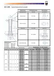
Büchsen mit Bund<br />
Bushings with flange<br />
<strong>WF</strong> <strong>750</strong><br />
3.1<br />
3.2<br />
3.3<br />
3.5<br />
3.6<br />
3.7<br />
3.8<br />
Büchsen nach DIN 9834 und<br />
Klammern nach DIN 9832<br />
Bushings acc DIN 9834 and<br />
clamps acc DIN 9832<br />
Büchsen und Klammern nach NAAMS<br />
Bushings and clamps acc. NAAMS<br />
Büchsen (mit Klammerfräsung) u. Klammern<br />
Bushings (with clamp milling) and clamps<br />
Büchsen<br />
Bushings<br />
Führungsbüchsen zum Einpressen<br />
und Eingießen<br />
Guide bushings for force in and cast in<br />
Büchsen<br />
Bushings<br />
Büchsen<br />
Bushings<br />
3.10 Büchsen<br />
Bushings<br />
3.11 Büchsen<br />
Bushings<br />
3.12 Büchsen<br />
Bushings<br />
3.14 Büchsen<br />
Bushings<br />
3.15 Büchsen<br />
Bushings<br />
3.19 Büchsen<br />
Bushings<br />
3.20<br />
Büchsen und Klammern<br />
Bushings and clamps<br />
3<br />
21
3.1<br />
22<br />
Büchsen nach DIN 9834 und Klammern nach DIN 9832<br />
Bushings acc. DIN 9834 and clamps acc. DIN 9832<br />
<br />
<br />
<strong>WF</strong> <strong>750</strong>/1A<br />
Ident-Nr.<br />
Code-No.<br />
18 798<br />
18 799<br />
18 797<br />
ød L ød1 ød2 L1 L2 L3 r<br />
25<br />
18 796 24<br />
32<br />
40<br />
32 40<br />
22<br />
30<br />
32<br />
18 800 32 50 40 50 40<br />
6,3<br />
18 801 40 63 50 63 50 5<br />
18 802 50 71 63 71 56 6,3 5<br />
18 803 63 80 80 90 63<br />
10<br />
4<br />
8 6<br />
18 804 80 100 100 112 80 10 8<br />
18 808<br />
100<br />
100 125 125 140<br />
18 805 106<br />
12,5 10<br />
18 806 125 160 160 180 132<br />
12<br />
16<br />
18 807 160 200 200 220 170 18<br />
zugehörige Klammer Ident-Nr.<br />
accompanying clamp Code-No.<br />
3 19 798<br />
19 784/19 785 Fa. OPEL<br />
19 799<br />
Maße ohne Toleranzangabe DIN ISO 2768 mittel / Measurements without a tolerance specification - DIN ISO 2768 medium<br />
Führungssäulen siehe 17.1 und 17.3 / Guide posts see 17.1 and 17.3<br />
Ident-Nr.<br />
Code-No.<br />
b<br />
h9<br />
L<br />
0<br />
-0,4<br />
h<br />
h11 b1<br />
b2<br />
+0,3<br />
0<br />
h1<br />
+0,2<br />
0<br />
h2<br />
0<br />
-0,3<br />
ød1<br />
+0,2<br />
0<br />
ød2<br />
+0,2<br />
0<br />
19 798 20 20 10 7,5 5 7 6,3 7 11<br />
19 799 32 32 16 11 10 11,5 10 11,5 17,5<br />
19 784 25 20 12 10 5 8,5 6,3 9 15<br />
19 785 32 25 16 11 10 11,5 6,3 11 18<br />
Stahlsorte C 45 K oder St 37-2 / Type of steel C45 K or St 37-2<br />
Edition 2009 Rev. 0
Büchsen und Klammern nach NAAMS<br />
Bushings and clamps acc. NAAMS<br />
<strong>WF</strong> <strong>750</strong>/1A<br />
Ident-Nr.<br />
Code-No.<br />
Edition 2009 Rev. 0<br />
ød L ød1 ød2 L1 L2 r<br />
18 809 25 40 32 40 30<br />
18 810 32 50 40 50 40<br />
18 811 40 63 50 63 50 5<br />
18 812 50 71 63 71 56 6 5<br />
18 813 63 80 80 90 63 8 6<br />
18 814 80 100 100 112 80 10 8<br />
18 815 100 125 125 140 106<br />
18 817 115 140 140 155 120<br />
18 816 125 160 160 180 132 12<br />
4<br />
12<br />
3<br />
10<br />
zugehörige Klammer Ident-Nr.<br />
accompanying clamp Code-No.<br />
19 786 oder/or 19 787<br />
Maße ohne Toleranzangabe DIN ISO 2768 mittel / Measurements without a tolerance specification - DIN ISO 2768 medium<br />
Ident-Nr. 19 787<br />
Code-No. 19 787<br />
Stahlsorte C 45 K oder St 37-2<br />
Type of steel C 45 K or St 37-2<br />
<br />
<br />
Ident-Nr. 19 786<br />
Code-No. 19 786<br />
3.2<br />
23
3.3<br />
24<br />
Büchsen (mit Klammerfräsung) und Klammern<br />
Bushings (with clamp milling) and clamps<br />
<br />
<br />
<strong>WF</strong> <strong>750</strong>/1A<br />
Ident-Nr.<br />
Code-No.<br />
ød L<br />
19 000 16 25<br />
19 001 20<br />
32<br />
ød1<br />
h6<br />
ød2<br />
-0,8<br />
L1<br />
+0,5<br />
+0,3<br />
L2<br />
-0,1<br />
L3<br />
-0,4<br />
b<br />
±0,25<br />
r1 r2<br />
r3<br />
-0,4<br />
zugehörige Klammer<br />
accompanying clamp<br />
Ident-Nr. /Code-No.<br />
19 002 25<br />
25<br />
32<br />
32<br />
40<br />
10 5<br />
2<br />
3<br />
4<br />
3<br />
3,5<br />
3<br />
4<br />
1 1<br />
19 790<br />
19 003<br />
19 004<br />
19 005<br />
32<br />
40<br />
50<br />
50<br />
63<br />
72<br />
40<br />
50<br />
63<br />
50<br />
63<br />
75<br />
13<br />
14<br />
8<br />
6<br />
4<br />
5<br />
6<br />
5<br />
6<br />
1,6 1,6<br />
19 791<br />
19 792<br />
19 006<br />
19 007<br />
63<br />
80<br />
80<br />
100<br />
80<br />
100<br />
95<br />
120<br />
17<br />
20<br />
10 8<br />
8<br />
10<br />
8<br />
2<br />
2,5<br />
2<br />
2,5<br />
19 793<br />
19 008 100 125 125 150 25<br />
10 3,2 3,2<br />
19 009<br />
19 010<br />
19 011<br />
125<br />
140<br />
160<br />
160<br />
180<br />
200<br />
160<br />
180<br />
200<br />
190<br />
210<br />
240<br />
30<br />
16 10<br />
12<br />
13<br />
13<br />
16<br />
18<br />
4<br />
5<br />
6<br />
4<br />
6<br />
19 794<br />
Maße ohne Toleranzangabe DIN ISO 2768 mittel / Measurements without a tolerance specification - DIN ISO 2768 medium<br />
Führungssäulen siehe Kat. 17.1 und 17.3 / Guide posts see Cat. 17.1 and 17.3<br />
Klammer Ident-Nr.<br />
Clamp Code-No.<br />
Büchsen-Innen ø<br />
Bushing-inside ø<br />
b<br />
h9<br />
L<br />
-0,4<br />
h<br />
h11<br />
b 1<br />
+0,2<br />
b2<br />
+0,3<br />
h 1<br />
+0,1<br />
h 2<br />
+0,2<br />
L 1<br />
+0,2<br />
ø d 1<br />
+0,2<br />
ø d 2<br />
+0,2<br />
Zylinderschraube<br />
Cheese head srew<br />
DIN 912<br />
19 790 16-32<br />
20 10 5 5<br />
-<br />
1 x M6<br />
20<br />
12,5<br />
7<br />
7 11<br />
19 791 40<br />
12<br />
2 x M6<br />
40<br />
8 20<br />
19 792 50 25 14 15,5 6 9 9,5 14,5 2 x M8<br />
19 793 63-80 28 50 16 18 8 10 11,5 25 11,5 17,5 2 x M10<br />
19 794 100-160 40 60 25 27 14 16 13,5 30 14 20 2 x M12<br />
Werkstoff für Klammern: St 37 oder C 45 K / Clamp material: St 37 or C 45 K<br />
Schnitt A-A<br />
View A-A<br />
bis ø = 63 mm eine Klammerfräsung<br />
up to ø = 63 mm one clamp milling<br />
Edition 2009 Rev. 0
Büchsen<br />
Bushings<br />
Edition 2009 Rev. 0<br />
<strong>WF</strong> <strong>750</strong>/1A<br />
Ident-Nr.<br />
Code-No.<br />
ød L ød1 ød2 L1 r<br />
19 300 20 35 28 36<br />
19 301 32 55 40 50<br />
19 302 40<br />
19 303 42<br />
19 304 50<br />
19 305 52<br />
70 50 60<br />
75 63 75<br />
19 306 63 80 80 90<br />
19 307 80 100 100 110<br />
19 308 100 125 125 135<br />
8<br />
2<br />
6<br />
12 8<br />
Maße ohne Toleranzangabe DIN ISO 2768 mittel / Measurements<br />
without a tolerance specification - DIN ISO 2768 medium<br />
<br />
<br />
3.5<br />
25
3.6<br />
26<br />
Führungsbüchsen zum Einpressen<br />
Force in guide bushings<br />
<br />
<br />
Führungsbüchse zum Einpressen, Type „A“<br />
Force in guide bushing, style „A“<br />
Einzelheit X / Detail X<br />
für d = 40 / for d = 40<br />
<strong>WF</strong> <strong>750</strong>/1A<br />
Ident-Nr.<br />
Code-No.<br />
18 700<br />
Type<br />
Style<br />
Einzelheit X / Detail X<br />
für d > 40 / for d > 40<br />
ød L ød1 ød2 L1 L2 L3 r<br />
40 63 52 60 8 –<br />
18 701 50 80 63 71 10 8<br />
18 702 A 63 100 80 90 12<br />
18 703 80 125 100 112 16<br />
18 704 100 160 125 140 20<br />
8<br />
10 10<br />
Maße ohne Toleranzangabe DIN ISO 2768 mittel / Measurements without a tolerance specification - DIN ISO 2768 medium<br />
3<br />
4<br />
Edition 2009 Rev. 0
Führungsbüchsen zum Eingießen<br />
Cast in guide bushings<br />
<strong>WF</strong> <strong>750</strong>/1A<br />
Ident-Nr.<br />
Code-No.<br />
Edition 2009 Rev. 0<br />
Type<br />
Style<br />
+2<br />
+1 1<br />
Führungsbüchse zum Eingießen, Type „B“<br />
Cast in guide bushing, style „B“<br />
Vorbereitet zum Eingießen einer Füllmasse zwischen Gehäusebohrung und Büchse<br />
Prepared for cast of a filler inbetween the case borehole and the bushing<br />
Einzelheit X / Detail X<br />
für d > 40 / for d > 40<br />
18 714<br />
<br />
<br />
ød L ød1 ød2 L1 L2 L3 r<br />
40 63 52 60 8 –<br />
18 715 50 80 63 71 10 8<br />
18 716 B 63 100 80 90 12<br />
18 717 80 125 100 112 16<br />
18 718 100 160 125 140 20<br />
Einzelheit X / Detail X<br />
für d = 40 / for d = 40<br />
Maße ohne Toleranzangabe DIN ISO 2768 mittel / Measurements without a tolerance specification - DIN ISO 2768 medium<br />
10<br />
–<br />
3<br />
4<br />
3.6<br />
27
3.7<br />
28<br />
Büchsen<br />
Bushings<br />
<br />
<br />
Einzelheit X / Detail X<br />
<strong>WF</strong> <strong>750</strong>/1A<br />
Ident-Nr.<br />
Code-No.<br />
ød L ød1 ød2 L1 L2 r r1 r2<br />
17 100 25 40 35 45 33 7 10<br />
17 101 30 50 40 50 40<br />
17 102 40 70 55 65 60<br />
17 103 50<br />
65 75<br />
17 104 60 80 75 85<br />
10 20<br />
Maße ohne Toleranzangabe DIN ISO 2768 mittel / Measurements without a tolerance<br />
specification - DIN ISO 2768 medium<br />
70<br />
17 105<br />
17 106<br />
65<br />
120<br />
80 90<br />
110<br />
17 107<br />
100<br />
90<br />
80 100 110<br />
17 108 140 130<br />
17 109<br />
100<br />
90<br />
100 120 130<br />
17 110 140 130<br />
1<br />
2<br />
2<br />
3<br />
Edition 2009 Rev. 0
Büchsen<br />
Bushings<br />
<br />
<br />
<br />
<br />
<strong>WF</strong> <strong>750</strong>/1A<br />
Ident-Nr.<br />
Code-No.<br />
Edition 2009 Rev. 0<br />
ød L ød1 ød2 L1 L2 r1 r2<br />
17 115 25<br />
35 40<br />
43<br />
17 116 30 42 47<br />
17 117<br />
60<br />
35,5<br />
40<br />
50 60<br />
17 118 64 39,5<br />
17 119<br />
77<br />
44,5<br />
50<br />
63 72<br />
17 120 92 55,5<br />
17 121 60 78<br />
17 122<br />
95<br />
17 123 63 100<br />
17 124 108<br />
80<br />
24,0 7,5 3<br />
86 49,0 7,5 3<br />
90<br />
55,5<br />
62,5<br />
6<br />
8<br />
4<br />
8 4<br />
Maße ohne Toleranzangabe DIN ISO 2768 mittel / Measurements without a tolerance<br />
specification - DIN ISO 2768 medium<br />
2<br />
3<br />
<br />
<br />
3.8<br />
29
Büchsen<br />
Bushings<br />
Edition 2009 Rev. 0<br />
<br />
<br />
ød 9 10 14 15 18 20 22 24 30 32 40 42<br />
ød1 14 14 20 20 26 26 30 30 42 42 54 54<br />
ød2 18 18 25 25 31 31 35 35 47 47 60 60<br />
L2 3 3 9 9 9 9 9 9 9 9 12 12<br />
L3 3 3 6 6 6 6 6 6 6 6 10 10<br />
L4 2 2 3 3 3 3 3 3 3 3 4 4<br />
r 1 1 1,5 1,5 1,5 1,5 2 2 2 2 3 3<br />
L L1<br />
H7<br />
15 12 17 874 17 400<br />
20 17 17 875 17 401<br />
25 22 17 876 17 879<br />
30 27 17 877 17 880<br />
39 36 17 878 17 881<br />
<strong>WF</strong> <strong>750</strong>/1A Ident-Nr.<br />
Code-No.<br />
26 17 17 402 17 406 17 410 17 415 17 421 17 427<br />
31 22 17 403 17 407 17 411 17 416 17 422 17 428<br />
36 27 17 404 17 408 17 412 17 417 17 423 17 429 17 434 17 440<br />
45 36 17 405 17 409 17 413 17 418 17 424 17 430 17 435 17 441<br />
55 46 17 882 17 884 17 414 17 419 17 425 17 431 17 436 17 442<br />
65 56 17 883 17 885 17 886 17 420 17 426 17 432 17 437 17 443<br />
68 56 17 446 17 450<br />
75 66 17 887 17 888 17 889 17 433 17 894 17 897<br />
78 66 17 992 17 996<br />
85 76 14 541 14 548 17 890 17 892 17 438 17 444<br />
88 76 17 447 17 451<br />
95 86 17 891 17 893 17 439 17 445<br />
98 86 17 993 17 997<br />
105 96 17 895 17 898<br />
108 96 17 448 17 452<br />
125 116 17 896 17 899<br />
128 116 17 449 17 453<br />
148 136 17 994 17 998<br />
168 156 17 995 17 999<br />
Maße ohne Toleranzangabe DIN ISO 2768 mittel / Measurements without a tolerance specification - DIN ISO 2768 medium<br />
3.10<br />
31
3.11<br />
32<br />
Büchsen<br />
Bushings<br />
<br />
<br />
ød 9 10 14 15 18 20 22 24 30 32 40 42<br />
ød1 14 14 20 20 26 26 30 30 42 42 54 54<br />
ød2 16 16 25 25 31 31 35 35 47 47 60 60<br />
L2 5 5 6 6 8 8 8 8 8 8 10 10<br />
L3 3 3 6 6 6 6 6 6 6 6 10 10<br />
L4 2 2 3 3 3 3 3 3 3 3 4 4<br />
r 1 1 1,5 1,5 1,5 1,5 2 2 2 2 3 3<br />
L L1<br />
17 12 17 213 17 216<br />
22 17 17 460 17 464<br />
23 17 17 468 17 474<br />
25 17 17 223 17 225<br />
27 22 17 461 17 465<br />
28 22 17 469 17 475<br />
<strong>WF</strong> <strong>750</strong>/1A Ident-Nr.<br />
Code-No.<br />
30 22 17 480 17 486 17 492 17 499<br />
32 27 17 462 17 466<br />
33 27 17 470 17 476<br />
35 27 17 481 17 487 17 493 17 970 17 976 17 984<br />
41 36 17 463 17 467<br />
42 36 17 471 17 477<br />
44 36 17 482 17 488 17 494 17 971 17 977 17 985<br />
51 46 17 214 17 217<br />
52 46 17 472 17 478<br />
54 46 17 483 17 489 17 495 17 972 17 978 17 986<br />
56 46 17 295 17 362<br />
61 56 17 215 17 218<br />
62 56 17 473 17 479<br />
Maße ohne Toleranzangabe DIN ISO 2768 mittel / Measurements without a tolerance specification - DIN ISO 2768 medium<br />
H7<br />
Edition 2009 Rev. 0
Büchsen<br />
Bushings<br />
Edition 2009 Rev. 0<br />
H7<br />
Maße ohne Toleranzangabe DIN ISO 2768 mittel / Measurements without a tolerance specification - DIN ISO 2768 medium<br />
<br />
<br />
ød 14 15 18 20 22 24 30 32 40 42<br />
ød1 20 20 26 26 30 30 42 42 54 54<br />
ød2 25 25 31 31 35 35 47 47 60 60<br />
L2 6 6 8 8 8 8 8 8 10 10<br />
L3 6 6 6 6 6 6 6 6 10 10<br />
L4 3 3 3 3 3 3 3 3 4 4<br />
r 1,5 1,5 1,5 1,5 2 2 2 2 3 3<br />
L L1<br />
<strong>WF</strong> <strong>750</strong>/1A Ident-Nr.<br />
Code-No.<br />
64 56 17 484 17 490 17 496 17 973 17 979 17 987<br />
66 56 17 296 17 363<br />
72 66 17 219 17 221<br />
74 66 17 485 17 491 17 497 17 974 17 980 17 988<br />
76 66 17 297 17 364<br />
82 76 17 220 17 222<br />
84 76 17 224 17 226 17 498 17 975 17 981 17 989<br />
86 76 17 298 17 365<br />
94 86 17 227 17 288 17 982 17 990<br />
96 86 17 299 17 366<br />
104 96 17 228 17 289 17 983 17 991<br />
106 96 17 300 17 367<br />
124 116 17 229 17 290 17 291 17 293<br />
126 116 17 358 17 368<br />
144 136 17 292 17 294<br />
146 136 17 359 17 369<br />
166 156 17 360 17 398<br />
206 196 17 361 17 399<br />
3.11<br />
33
Büchsen<br />
Bushings<br />
Edition 2009 Rev. 0<br />
<br />
<br />
ød 9 10 12 14 15 16 18 20 22 24 30 32 40 42 50 60<br />
ød1 14 14 18 20 20 22 26 26 30 30 42 42 54 54 66 80<br />
ød2 16 16 23 25 25 27 31 31 35 35 47 47 60 60 72 86<br />
L1 3 3 6 6 6 6 6 6 6 6 6 6 10 10 10 20<br />
L2 2 2 3 3 3 3 3 3 3 3 3 3 4 4 4 4<br />
r 1 1 1,5 1,5 1,5 1,5 1,5 1,5 2 2 2 2 3 3 3 3<br />
L<br />
12 17 830 17 900<br />
<strong>WF</strong> <strong>750</strong>/1A Ident-Nr.<br />
Code-No.<br />
17 17 831 17 901 17 902 17 903 17 907 17 911 17 915 17 920 17 926 17 932<br />
22 17 832 17 835 17 838 17 904 17 908 17 912 17 916 17 921 17 927 17 933<br />
27 17 833 17 836 17 839 17 905 17 909 17 913 17 917 17 922 17 928 17 934 17 939 17 945<br />
36 17 834 17 837 17 840 17 906 17 910 17 914 17 918 17 923 17 929 17 935 17 940 17 946<br />
46 17 841 17 843 17 845 17 919 17 924 17 930 17 936 17 941 17 947<br />
56 17 842 17 844 17 846 17 847 17 925 17 931 17 937 17 942 17 948 17 951 17 955<br />
66 17 848 17 849 17 850 17 938 17 855 17 858 17 861 17 865<br />
76 17 851 17 853 17 943 17 949 17 952 17 956 17 959<br />
86 17 852 17 854 17 856 17 859 17 862 17 866 17 869<br />
96 17 944 17 950 17 953 17 957 17 960 17 963<br />
116 17 857 17 860 17 954 17 958 17 961 17 964<br />
136 17 863 17 867 17 962 17 965<br />
156 17 864 17 868 17 870 17 872<br />
196 17 871 17 873<br />
Maße ohne Toleranzangabe DIN ISO 2768 mittel / Measurements without a tolerance specification - DIN ISO 2768 medium<br />
3.12<br />
35
3.14<br />
36<br />
Büchsen<br />
Bushings<br />
<br />
<br />
ød 10 12 13 14 15 16 20 25 30 31,5 35<br />
ød1 14 18 19 20 21 22 30 35 40 40 45<br />
ød2 22 25 26 27 28 29 40 45 50 50 60<br />
L1 2 3 3 3 3 3 5 5 5 5 5<br />
L2 2 3 3 3 3 3 3 3 3 3 4<br />
r 1 1 1,5 1,5 1,5 1,5 1,5 2 2 2 2<br />
L<br />
<strong>WF</strong> <strong>750</strong>/1A Ident-Nr.<br />
Code-No.<br />
15 17 500 17 502 17 504 17 506 17 508 17 511 17 514<br />
20 17 501 17 503 17 505 17 507 17 509 17 512 17 515 17 518 13 560<br />
25 17 510 17 513 17 519 14 790 14 060<br />
30 13 458 17 516 17 520 17 522 17 527<br />
35 14 925 17 523 17 526<br />
40 17 517 17 521 17 524 17 528<br />
50 17 525 17 529<br />
Maße ohne Toleranzangabe DIN ISO 2768 mittel / Measurements without a tolerance specification - DIN ISO 2768 medium<br />
Edition 2009 Rev. 0
Büchsen<br />
Bushings<br />
Edition 2009 Rev. 0<br />
<br />
<br />
ød 40 45 50 55 60 63 70 75 80 90 100 120<br />
ød1 50 55 60 65 75 75 85 90 100 110 120 140<br />
ød2 65 70 75 80 90 85 105 110 120 130 150 170<br />
L1 5 5 5 5 7,5 7,5 7,5 7,5 10 10 10 10<br />
L2 4 4 4 4 4 4 4 4 5 5 5 5<br />
r 2 2 2 2 3 3 3 3 3 3 3 3<br />
L<br />
30 17 530 17 533 17 536<br />
<strong>WF</strong> <strong>750</strong>/1A Ident-Nr.<br />
Code-No.<br />
35<br />
40 17 531 17 534 17 537 17 539 17 541<br />
50 17 532 17 097 17 111 17 542 17 545<br />
60 17 535 17 538 17 540 17 547 17 548 17 091<br />
67,5 17 544<br />
80 17 543 17 546 17 549 17 092 17 093 17 095<br />
100 17 090 17 094 17 096<br />
Maße ohne Toleranzangabe DIN ISO 2768 mittel / Measurements without a tolerance specification - DIN ISO 2768 medium<br />
3.14<br />
37
3.15<br />
38<br />
Büchsen<br />
Bushings<br />
<br />
<br />
ød 9 10 12 14 15 16 18 20 22 24 30 32 40 42<br />
ød1 14 14 18 20 20 22 26 26 30 30 42 42 54 54<br />
ød2 16 16 23 25 25 27 31 31 35 35 47 47 60 60<br />
ø d3 13,4 13,4 17 19 19 21 24,9 24,9 28,6 28,6 39,5 39,5 51 51<br />
L2 3 3 6 6 6 6 6 6 6 6 6 6 10 10<br />
L3 1,1 1,1 1,3 1,3 1,3 1,3 1,3 1,3 1,6 1,6 1,85 1,85 2,15 2,15<br />
L4 20 20 24 30 30 32 40 40 48 48 64 64 80 80<br />
L L1<br />
12 6,6 16 040 16 048<br />
<strong>WF</strong> <strong>750</strong>/1A Ident-Nr.<br />
Code-No.<br />
17 8,3 16 056 16 063 16 070 16 083 16 092<br />
17 11,6 16 041 16 049<br />
22 12,6 16 101 16 111<br />
22 13,3 16 057 16 064 16 071 16 077 16 084 16 093<br />
22 16,6 16 042 16 050<br />
27 15,85 16 121 16 170<br />
27 17,6 16 102 16 112<br />
27 18,3 16 058 16 065 16 072 16 078 16 085 16 094<br />
27 21,6 16 043 16 051<br />
36 24,85 16 122 16 171<br />
36 26,6 16 103 16 113<br />
36 27,3 16 059 16 066 16 073 16 079 16 086 16 095<br />
36 30,6 16 044 16 052<br />
46 30,15 16 180 16 189<br />
46 34,85 16 123 16 172<br />
46 36,6 16 104 16 114<br />
46 37,3 16 060 16 067 16 074 16 080 16 087 16 096<br />
46 40,6 16 045 16 053<br />
Einzelheit X<br />
Detail X<br />
Maße ohne Toleranzangabe DIN ISO 2768 mittel / Measurements without a tolerance specification - DIN ISO 2768 medium<br />
H7<br />
Edition 2009 Rev. 0
Büchsen<br />
Bushings<br />
Maße ohne Toleranzangabe DIN ISO 2768 mittel / Measurements without a tolerance specification - DIN ISO 2768 medium<br />
Edition 2009 Rev. 0<br />
<br />
<br />
ød 9 10 12 14 15 16 18 20 22 24 30 32 40 42<br />
ød1 14 14 18 20 20 22 26 26 30 30 42 42 54 54<br />
ød2 16 16 23 25 25 27 31 31 35 35 47 47 60 60<br />
ø d3 13,4 13,4 17 19 19 21 24,9 24,9 28,6 28,6 39,5 39,5 51 51<br />
L2 3 3 6 6 6 6 6 6 6 6 6 6 10 10<br />
L3 1,1 1,1 1,3 1,3 1,3 1,3 1,3 1,3 1,6 1,6 1,85 1,85 2,15 2,15<br />
L4 20 20 24 30 30 32 40 40 48 48 64 64 80 80<br />
L L1<br />
<strong>WF</strong> <strong>750</strong>/1A Ident-Nr.<br />
Code-No.<br />
56 40,15 16 181 16 190<br />
56 44,85 16 124 16 173<br />
56 46,6 16 105 16 115<br />
56 47,3 16 061 16 068 16 075 16 081 16 088 16 097<br />
56 50,6 16 046 16 054<br />
H7<br />
Einzelheit X<br />
Detail X<br />
66 50,15 16 182 16 191<br />
66 54,85 16 125 16 174<br />
66 56,6 16 106 16 116<br />
66 57,3 16 089 16 098<br />
76 60,15 16 183 16 192<br />
76 64,85 16 126 16 175<br />
76 66,6 16 107 16 117<br />
76 67,3 16 090 16 099<br />
86 70,15 16 184 16 193<br />
86 74,85 16 127 16 176<br />
86 76,6 16 108 16 118<br />
96 80,15 16 185 16 194<br />
96 84,85 16 128 16 177<br />
96 86,6 16 109 16 119<br />
116 100,15 16 186 16 195<br />
116 104,85 16 129 16 178<br />
136 120,15 16 187 16 196<br />
3.15<br />
39
3.19<br />
40<br />
Büchsen<br />
Bushings<br />
<br />
<br />
ød 9 10 15 18 20 20 22 24 24 30 32<br />
ød1 14 14 20 26 26 26 30 30 30 42 42<br />
ød2 16 16 25 31 31 31 35 35 35 47 47<br />
L2 6 9 17 17 17 22 22 22 27 27 27<br />
L3 3 3 6 6 6 6 6 6 6 6 6<br />
L4 2 2 3 3 3 3 3 3 3 3 3<br />
r 1 1 1,5 1,5 1,5 1,5 2 2 2 2 2<br />
L L1<br />
15 9 17 966<br />
26 17 17 967<br />
39 22 17 968 17 454 17 455<br />
<strong>WF</strong> <strong>750</strong>/1A Ident-Nr.<br />
Code-No.<br />
49 27 17 969 17 456 17 457<br />
63 36 17 714 17 458 17 459<br />
73 46 17 715<br />
Maße ohne Toleranzangabe DIN ISO 2768 mittel / Measurements without a tolerance specification - DIN ISO 2768 medium<br />
Edition 2009 Rev. 0
Büchsen und Klammern<br />
Bushings and clamps<br />
<strong>WF</strong> <strong>750</strong>/1A<br />
Ident-Nr.<br />
Code-No.<br />
18 299 23<br />
18 300 25<br />
Edition 2009 Rev. 0<br />
ød L ød1 ød2 L1 L2 r<br />
40 32 40 6 3<br />
5<br />
<br />
<br />
zugehörige Klammer<br />
accompanying clamp<br />
Ident-Nr. /Code-No.<br />
19 780<br />
18 301 32 50 40 50 10 5 19 781<br />
18 302 40<br />
18 303 42<br />
18 304 50<br />
18 305 52<br />
63 50 63 13<br />
72 63 75<br />
18 306 63<br />
17<br />
80 80 95<br />
18 307 65 16<br />
18 308 80<br />
18 309 82<br />
14<br />
100 100 120 20<br />
18 310 100 125 125 150 25<br />
10<br />
16<br />
18 311 125 160 160 190 30 13<br />
8 6 19 782<br />
10 8 19 783<br />
19 794<br />
Maße ohne Toleranzangabe DIN ISO 2768 mittel / Measurements without a tolerance specification - DIN ISO 2768 medium<br />
Klammer Ident-Nr.<br />
Clamp Code-No.<br />
Büchsen-Innen ø<br />
Bushing-inside ø<br />
Form A / Schnitt A-A<br />
Style A / View A-A<br />
b<br />
L<br />
-0,4<br />
L1<br />
h<br />
h11<br />
h1<br />
-0,1<br />
h2<br />
+0,4<br />
b1 b2<br />
19 780 25<br />
16 6 3 3,2 12 4<br />
20<br />
-<br />
19 781 32 20 10 5 6,8 12,5 5<br />
ø d 1<br />
H13<br />
ø d 2<br />
H13<br />
S c h r a u b e n<br />
Screws<br />
6,6 13 1 x M6<br />
19 782 40-50 25 40 20 14 8 9 16 7 9,0 15 2 x M8<br />
19 783 63-80 32 50 25 16 10 11 20,5 9 11,5 18 2 x M10<br />
19 794 100-125 40 60 30 25 16 13 27 14 13,5 20 2 x M12<br />
Werkstoff für Klammern: St 37 oder C 45 K / Clamp material: St 37 or C 45 K<br />
Form B / Schnitt A-A<br />
Style B / View A-A<br />
F o r m<br />
Style<br />
A<br />
B<br />
3.20<br />
41
Edition 2009 Rev. 0<br />
Büchsen mit Anlaufbund<br />
Bushings with buffer flange<br />
<strong>WF</strong> <strong>750</strong><br />
4.1<br />
Büchsen mit Anlaufbund<br />
Bushings with buffer flange<br />
4<br />
43
Büchsen mit Anlaufbund<br />
Bushings with buffer flange<br />
<strong>WF</strong> <strong>750</strong>/1A<br />
Ident-Nr.<br />
Code-No.<br />
Edition 2009 Rev. 0<br />
ød L ød1 ød2 L1 r<br />
19 691 12 15 18 25 4<br />
19 692 16 20 22 30<br />
19 693 20 25 28 36<br />
19 694 25 30 33 43<br />
19 695 30 35 38 48<br />
19 696 40 45 50 60<br />
Schnitt A-A<br />
View A-A<br />
19 697<br />
50 60 68<br />
50<br />
19 699 55 62 75 6<br />
19 698<br />
60<br />
83 7,5<br />
60<br />
75<br />
19 690 65 90 7<br />
Maße ohne Toleranzangabe DIN ISO 2768 mittel<br />
Measurements without a tolerance specification - DIN ISO 2768 medium<br />
5<br />
1<br />
2<br />
3<br />
<br />
<br />
4.1<br />
45
Edition 2009 Rev. 0<br />
Anlaufscheiben<br />
Washers<br />
<strong>WF</strong> <strong>750</strong><br />
6.1<br />
Anlaufscheiben<br />
Washers<br />
6<br />
47
Anlaufscheiben<br />
Washers<br />
<strong>WF</strong> <strong>750</strong>/1A<br />
Ident-Nr.<br />
Code-No.<br />
15 385 10,2<br />
Edition 2009 Rev. 0<br />
ød s ød1 ød2 tk<br />
30<br />
19 616 12,2 3 40<br />
19 617 16,2<br />
19 618 20,2<br />
19 619 25,2 55 40<br />
5 5,5<br />
19 620 30,2 60 45<br />
19 621 35,2 70 50<br />
19 622 40,2<br />
80<br />
60<br />
7<br />
19 623 45,3 90 6,6 67,5<br />
19 624 50,3<br />
100 75<br />
8<br />
19 625 60,3 120<br />
90<br />
19 626 70,3<br />
50<br />
Senkschrauben. Countersunk screw.<br />
<br />
<br />
DIN 7991 Stückzahl. Quantity.<br />
- - - -<br />
35<br />
130 9 100<br />
19 627 80,3 150 120<br />
19 628 90,5 10 170<br />
140<br />
19 629 100,5 190 11 160<br />
19 600 120,5 200 175<br />
Schnitt A-A<br />
View A-A<br />
Maße ohne Toleranzangabe DIN ISO 2768 mittel / Measurements without a tolerance specification - DIN ISO 2768 medium<br />
M5<br />
M6<br />
M8<br />
M10<br />
2<br />
4<br />
6.1<br />
49
50<br />
Gleitplatten / Wear plates<br />
<strong>WF</strong> <strong>750</strong>/1A mit Festschmierstoff, wenn nichts anderes angegeben<br />
<strong>WF</strong> <strong>750</strong>/1A with lubricant, if not other mentioned<br />
7.1<br />
7.2<br />
7.3<br />
7.7<br />
7.9<br />
Gleitplatten<br />
Wear plates<br />
Dicke / Thickness = 20 mm<br />
Gleitplatten<br />
Wear plates<br />
Dicke / Thickness = 20 mm<br />
Gleitplatten<br />
Wear plates<br />
Dicke / Thickness = 16 mm; 25 mm<br />
Gleitplatten<br />
Wear plates<br />
Dicke / Thickness = 8 mm; 12mm; 16 mm; 20 mm<br />
Gleitplatten<br />
Wear plates<br />
Dicke / Thickness = 8 mm; 10 mm<br />
7.11 Führungsplatten<br />
Guide plates<br />
Dicke / Thickness = 40 mm; 50 mm<br />
7.11<br />
7.12<br />
7.12<br />
Führungsplatten / Stahl gehärtet<br />
mit Festschmierstoff<br />
Guide plates steel hardened with lubricant<br />
Dicke / Thickness = 40 mm; 50 mm<br />
Gleitplatten / <strong>WF</strong> <strong>750</strong>/1A mit/ohne Festschmierstoff,<br />
Schmiernut<br />
Wear plates / <strong>WF</strong> <strong>750</strong>/1A with/without lubricant,<br />
oil groove<br />
Dicke / Thickness = 20 mm<br />
Gleitplatten / Stahl gehärtet ohne<br />
Festschmierstoff mit Schmiernut<br />
Wear plates / steel hardened without lubricant<br />
with oil groove<br />
Dicke / Thickness = 21 mm<br />
7.13 Gleitplatten<br />
Wear plates<br />
Dicke / Thickness = 16 mm<br />
7.14<br />
Gleitplatten nach VDI 3357<br />
Wear plates acc.to VDI 3357<br />
Dicke / Thickness = 20 mm<br />
Edition 2009 Rev. 0
Edition 2009 Rev. 0<br />
Gleitplatten / Wear plates<br />
<strong>WF</strong> <strong>750</strong>/1A mit Festschmierstoff, wenn nichts anderes angegeben<br />
<strong>WF</strong> <strong>750</strong>/1A with lubricant, if not other mentioned<br />
7.14<br />
Gleitplatten / Stahl gehärtet ohne Festschmierstoff<br />
nach VDI 3357<br />
Wear plates / steel hardened<br />
without lubricant acc. to VDI 3357<br />
Dicke / Thickness = 20 mm<br />
7.15 Gleitplatten<br />
Wear plates<br />
Dicke / Thickness = 10 mm<br />
7.16 Gleitplatten<br />
Wear plates<br />
Dicke / Thickness = 10 mm<br />
7.18 Gleitplatten<br />
Wear plates<br />
Dicke / Thickness = 5 mm<br />
7.19 Gleitplatten<br />
Wear plates<br />
Dicke / Thickness = 10 mm<br />
7.21<br />
7.21<br />
Gleitplatten nach VDI 3357<br />
Wear plates acc. to VDI 3357<br />
Dicke / Thickness = 12 mm<br />
Gleitplatten / Stahl gehärtet ohne<br />
Festschmierstoff nach VDI 3357<br />
Wear plates / steel hardened without<br />
lubricant acc. to VDI 3357<br />
Dicke / Thickness = 12 mm<br />
7.23 Führungsplatten<br />
Guide plates<br />
Dicke / Thickness = 30 mm; 38 mm<br />
7.25 Gleitplatten<br />
Wear plates<br />
Dicke / Thickness = 15 mm<br />
7.25<br />
7.26<br />
Gleitplatten / Stahl gehärtet ohne<br />
Festschmierstoff<br />
Wear plates / steel hardened without lubricant<br />
Dicke / Thickness = 15,1 mm<br />
Deck - Gleitplatten - Paarungen<br />
Cover - Wear plates - Pairings<br />
7<br />
51
7.1<br />
52<br />
Gleitplatten / <strong>WF</strong> <strong>750</strong>/1A mit Festschmierstoff<br />
Wear plates / <strong>WF</strong> <strong>750</strong>/1A with lubricant<br />
<br />
<br />
<strong>WF</strong> <strong>750</strong>/1A<br />
Ident-Nr.<br />
Code-No.<br />
Form B<br />
Style B<br />
18 030 50 x 80 x 20<br />
b x L x s L1 L2 ± 0,1 b1 ± 0,1<br />
18 330 50 x 100 x 20 55<br />
18 331 50 x 125 x 20 80<br />
20<br />
18 332 50 x 160 x 20 115<br />
18 333 50 x 200 x 20 155<br />
18 480 50 x 250 x 20 100 F<br />
18 484 80 x 50 x 20 25 –<br />
18 031 80 x 80 x 20<br />
18 334 80 x 100 x 20 55<br />
18 335 80 x 125 x 20 80<br />
18 336 80 x 160 x 20 20<br />
115<br />
18 337 80 x 200 x 20 155<br />
18 352 80 x 250 x 20 100<br />
18 481 80 x 315 x 20 132<br />
18 338 100 x 50 x 20 25 –<br />
18 339 100 x 80 x 20<br />
18 340 100 x 100 x 20 55<br />
18 341 100 x 125 x 20 20<br />
80<br />
18 342 100 x 160 x 20 115<br />
18 343 100 x 200 x 20 155<br />
35<br />
35<br />
35<br />
Form A<br />
Style A<br />
Form C<br />
Style C<br />
Maße ohne Toleranzangabe DIN ISO 2768 mittel / Measurements without a tolerance specification - DIN ISO 2768 medium<br />
–<br />
40<br />
60<br />
3<br />
s<br />
Schnitt A-A<br />
View A-A<br />
Form<br />
Style<br />
A<br />
D<br />
B<br />
C<br />
E<br />
D<br />
B<br />
C<br />
Edition 2009 Rev. 0
Gleitplatten / <strong>WF</strong> <strong>750</strong>/1A mit Festschmierstoff<br />
Wear plates / <strong>WF</strong> <strong>750</strong>/1A with lubricant<br />
<strong>WF</strong> <strong>750</strong>/1A<br />
Ident-Nr.<br />
Code-No.<br />
Edition 2009 Rev. 0<br />
Form E<br />
Style E<br />
b x L x s L1 L2 ± 0,1 b1 ± 0,1<br />
18 353 100 x 250 x 20<br />
100<br />
20<br />
18 482 100 x 315 x 20 132<br />
18 485 125 x 50 x 20 25 –<br />
18 344 125 x 80 x 20<br />
18 345 125 x 100 x 20 55<br />
18 346 125 x 125 x 20 80<br />
18 347 125 x 160 x 20 20<br />
115<br />
18 044 125 x 200 x 20 155<br />
18 354 125 x 250 x 20 100<br />
18 483 125 x 315 x 20 132<br />
18 486 160 x 50 x 20 25 –<br />
18 359 160 x 80 x 20<br />
Form D<br />
Style D<br />
18 348 160 x 100 x 20 55<br />
18 349 160 x 125 x 20 80<br />
18 350 160 x 160 x 20 20<br />
115<br />
18 351 160 x 200 x 20 155<br />
18 355 160 x 250 x 20 100<br />
18 356 160 x 315 x 20 132<br />
18 357 200 x 160 x 20<br />
115<br />
20<br />
18 358 200 x 200 x 20 155<br />
<br />
<br />
Form<br />
Style<br />
60 E<br />
35 B<br />
35<br />
Form F<br />
Style F<br />
85<br />
120<br />
D<br />
C<br />
E<br />
D<br />
C<br />
E<br />
160 C<br />
Maße ohne Toleranzangabe DIN ISO 2768 mittel / Measurements without a tolerance specification - DIN ISO 2768 medium<br />
7.1<br />
53
7.2<br />
54<br />
Gleitplatten / <strong>WF</strong> <strong>750</strong>/1A mit Festschmierstoff<br />
Wear plates / <strong>WF</strong> <strong>750</strong>/1A with lubricant<br />
<br />
<br />
<strong>WF</strong> <strong>750</strong>/1A<br />
Ident-Nr.<br />
Code-No.<br />
b x L x s L1<br />
17 180 28 x 75 x 20 45<br />
17 181 28 x 100 x 20 50<br />
17 184 28 x 125 x 20 75<br />
17 182 28 x 150 x 20 100<br />
17 183 38 x 75 x 20 45<br />
18 930 38 x 100 x 20 50<br />
13 269 38 x 125 x 20 75<br />
18 931 38 x 150 x 20 100<br />
17 185 38 x 200 x 20 150<br />
17 150 48 x 75 x 20 45<br />
17 151 48 x 100 x 20 50<br />
17 152 48 x 125 x 20 75<br />
17 153 48 x 150 x 20 100<br />
14 371 48 x 200 x 20 150<br />
17 189 58 x 75 x 20 45<br />
17 190 58 x 100 x 20 50<br />
17 191 58 x 150 x 20 100<br />
17 155 75 x 75 x 20 25<br />
17 157 75 x 100 x 20 50<br />
17 156 75 x 125 x 20 75<br />
18 933 75 x 150 x 20 100<br />
17 158 75 x 200 x 20 150<br />
Form A<br />
Style A<br />
Schnitt B-B<br />
View B-B<br />
Form<br />
Style<br />
Maße ohne Toleranzangabe DIN ISO 2768 mittel / Measurements without a tolerance specification - DIN ISO 2768 medium<br />
A<br />
s<br />
Schnitt A-A<br />
View A-A<br />
Edition 2009 Rev. 0
Gleitplatten / <strong>WF</strong> <strong>750</strong>/1A mit Festschmierstoff<br />
Wear plates / <strong>WF</strong> <strong>750</strong>/1A with lubricant<br />
<strong>WF</strong> <strong>750</strong>/1A<br />
Ident-Nr.<br />
Code-No.<br />
Edition 2009 Rev. 0<br />
b x L x s b1 L1<br />
18 932 75 x 100 x 20 25 50 C<br />
18 934 100 x 100 x 20<br />
17 160 100 x 125 x 20 75<br />
18 935 100 x 150 x 20 100<br />
17 162 100 x 200 x 20 150<br />
17 163 100 x 250 x 20 200<br />
14 799 100 x 300 x 20 200<br />
50<br />
15 291 125 x 125 x 20 75<br />
17 164 125 x 150 x 20 100<br />
17 165 125 x 200 x 20 150<br />
17 166 125 x 250 x 20 200<br />
14 805 125 x 300 x 20 250<br />
17 159 125 x 350 x 20 200<br />
17 167 150 x 150 x 20<br />
17 168 150 x 200 x 20 150<br />
100<br />
17 169 150 x 250 x 20 200<br />
17 192 150 x 300 x 20 250<br />
17 193 200 x 200 x 20<br />
Form B<br />
StyleB<br />
Form C<br />
Style C<br />
17 194 200 x 250 x 20 150<br />
200<br />
17 195 200 x 300 x 20 250<br />
Maße ohne Toleranzangabe DIN ISO 2768 mittel / Measurements without a tolerance specification - DIN ISO 2768 medium<br />
50<br />
100<br />
150<br />
<br />
<br />
Form<br />
Style<br />
B<br />
7.2<br />
55
7.3<br />
56<br />
Gleitplatten / <strong>WF</strong> <strong>750</strong>/1A mit Festschmierstoff<br />
Wear plates / <strong>WF</strong> <strong>750</strong>/1A with lubricant<br />
<br />
<br />
s<br />
<strong>WF</strong> <strong>750</strong>/1A<br />
Ident-Nr.<br />
Code-No.<br />
Schnitt A-A<br />
View A-A<br />
b x L x s L1 b1<br />
19 030 80 x 100 x 25 25<br />
19 031 80 x 125 x 25 37,5<br />
19 032 80 x 160 x 25 55<br />
15<br />
Zyl.-Schraube<br />
Cheese head screw<br />
M12 Stk./Pieces<br />
19 033 80 x 200 x 25 75 3<br />
19 034 100 x 125 x 25 37,5<br />
19 035 100 x 160 x 25 55<br />
19 036 100 x 200 x 25 75 3<br />
19 037 125 x 125 x 25 37,5 37,5 2<br />
Maße ohne Toleranzangabe DIN ISO 2768 mittel<br />
Measurements without a tolerance specification - DIN ISO 2768 medium<br />
25<br />
Einzelheit X<br />
Detail X<br />
2<br />
2<br />
Edition 2009 Rev. 0
Gleitplatten / <strong>WF</strong> <strong>750</strong>/1A mit Festschmierstoff<br />
Wear plates / <strong>WF</strong> <strong>750</strong>/1A with lubricant<br />
Edition 2009 Rev. 0<br />
s<br />
<strong>WF</strong> <strong>750</strong>/1A<br />
Ident-Nr.<br />
Code-No.<br />
Schnitt A-A<br />
View A-A<br />
b x L x s L1 b1<br />
19 038 60 x 100 x 16 25<br />
19 039 60 x 125 x 16 37,5<br />
19 040 60 x 160 x 16 55<br />
12,5<br />
Zyl.-Schraube<br />
Cheese head screw<br />
M10 Stk./Pieces<br />
19 041 60 x 200 x 16 75 3<br />
19 042 80 x 100 x 16 25<br />
19 043 80 x 125 x 16 37,5<br />
19 044 80 x 160 x 16 55<br />
19 045 80 x 200 x 16 75 3<br />
Maße ohne Toleranzangabe DIN ISO 2768 mittel<br />
Measurements without a tolerance specification - DIN ISO 2768 medium<br />
Y<br />
15<br />
Einzelheit Y<br />
Detail Y<br />
2<br />
2<br />
<br />
<br />
7.3<br />
57
7.7<br />
58<br />
Gleitplatten / <strong>WF</strong> <strong>750</strong>/1A mit Festschmierstoff<br />
Wear plates / <strong>WF</strong> <strong>750</strong>/1A with lubricant<br />
<br />
<br />
<strong>WF</strong> <strong>750</strong>/1A<br />
Ident-Nr.<br />
Code-No.<br />
18 070<br />
b<br />
-0,1<br />
L<br />
-0,5<br />
100<br />
s<br />
±0,025<br />
b1<br />
L1<br />
± 0,2<br />
60<br />
18 071 125 160 20 85 120<br />
18 072 250 210<br />
18 073<br />
100<br />
60<br />
18 074 100 160 16 60 120<br />
18 075 250 210<br />
18 076<br />
100<br />
60<br />
18 077 80 160 12 40 120<br />
18 078 250 210<br />
18 079<br />
100<br />
60<br />
18 080 80 160 20 40 120<br />
18 081 250 210<br />
18 082<br />
100<br />
60<br />
18 069 160 120<br />
60<br />
16 30<br />
18 083 160 120<br />
18 084 250 210<br />
18 085<br />
100<br />
60<br />
18 086 50 160 20 20 120<br />
18 087 250 210<br />
Form<br />
Style<br />
d1 d2 t<br />
Schnitt A-A<br />
View A-A<br />
Zyl.-Schraube DIN 912<br />
Cheese head screw<br />
DIN 912<br />
13,5 20 13 M12 x 25<br />
11 18 11 M10 x 20<br />
9 15 9 M8 x 20<br />
13,5 20 13 M12 x 25<br />
11 18 11 M10 x 20<br />
13,5 20 13 M12 x 25<br />
Maße ohne Toleranzangabe DIN ISO 2768 mittel / Measurements without a tolerance specification - DIN ISO 2768 medium<br />
Edition 2009 Rev. 0
Gleitplatten / <strong>WF</strong> <strong>750</strong>/1A mit Festschmierstoff<br />
Wear plates / <strong>WF</strong> <strong>750</strong>/1A with lubricant<br />
s<br />
<strong>WF</strong> <strong>750</strong>/1A<br />
Ident-Nr.<br />
Code-No.<br />
18 088<br />
Edition 2009 Rev. 0<br />
b<br />
-0,1<br />
L<br />
-0,5<br />
100<br />
s<br />
±0,025<br />
b1<br />
L1<br />
± 0,2<br />
60<br />
18 089 40 160 8 – 120<br />
18 090 250 210<br />
Form<br />
Style<br />
d1 d2 t<br />
<br />
<br />
Senkschraube DIN 7991<br />
Countersunk head screw<br />
DIN 7991<br />
9 16,4 5 M8 x 15<br />
Maße ohne Toleranzangabe DIN ISO 2768 mittel / Measurements without a tolerance specification - DIN ISO 2768 medium<br />
<strong>WF</strong> <strong>750</strong>/1A<br />
Ident-Nr.<br />
Code-No.<br />
18 091<br />
b<br />
-0,1<br />
L<br />
-0,5<br />
100<br />
s<br />
±0,025<br />
b1<br />
L1<br />
± 0,2<br />
60<br />
18 092 40 160 12 – 120<br />
18 093 250 210<br />
18 094<br />
100<br />
60<br />
18 095 40 160 16 – 120<br />
18 096 250 210<br />
18 097<br />
100<br />
Einzelheit X<br />
Detail X<br />
Einzelheit Y<br />
Detail Y<br />
60<br />
18 098 30 160 12 – 120<br />
18 099 250 210<br />
Form<br />
Style<br />
d1 d2 t<br />
Zyl.-Schraube DIN 912<br />
Cheese head screw<br />
DIN 912<br />
9 15 9 M8 x 20<br />
11 18 11 M10 x 20<br />
9 15 9 M8 x 20<br />
Maße ohne Toleranzangabe DIN ISO 2768 mittel / Measurements without a tolerance specification - DIN ISO 2768 medium<br />
7.7<br />
59
Gleitplatten / <strong>WF</strong> <strong>750</strong>/1A mit Festschmierstoff<br />
Wear plates / <strong>WF</strong> <strong>750</strong>/1A with lubricant<br />
s k9<br />
<strong>WF</strong> <strong>750</strong>/1A<br />
Ident-Nr.<br />
Code-No.<br />
Edition 2009 Rev. 0<br />
b L s L1 L2<br />
16 700 16 40<br />
15<br />
8<br />
16 701 18 50 28<br />
16 702 20 63<br />
Schnitt A-A<br />
View A-A<br />
L2 = Festschmierstofffreie Zone für Befestigung<br />
L2 = Area without solid lubricant macro-depots for fastening.<br />
16 703 25 71 10<br />
40<br />
16 704 28 80 50<br />
Maße ohne Toleranzangabe DIN ISO 2768 mittel<br />
Measurements without a tolerance specification - DIN ISO 2768 medium<br />
32<br />
6<br />
7<br />
<br />
<br />
7.9<br />
61
7.11<br />
62<br />
Führungsplatten / <strong>WF</strong> <strong>750</strong>/1A mit Festschmierstoff<br />
Guide plates / <strong>WF</strong> <strong>750</strong>/1A with lubricant<br />
<br />
<br />
<strong>WF</strong> <strong>750</strong>/1A<br />
Ident-Nr.<br />
Code-No.<br />
Schnitt A-A<br />
View A-A<br />
b x L x s L1 L2 ø d<br />
Anzahl der Schrauben<br />
Quantity screws<br />
19 550 30 x 150 x 40 50<br />
–<br />
3<br />
19 551 30 x 200 x 40<br />
75<br />
19 552 30 x 250 x 40 50 4<br />
14<br />
19 553 40 x 150 x 40 50<br />
– 3<br />
19 554 40 x 200 x 40<br />
75<br />
19 555 40 x 250 x 40 50 4<br />
19 556 45 x 150 x 50 50<br />
–<br />
3<br />
19 557 45 x 200 x 50<br />
75<br />
19 558 45 x 250 x 50 50 4<br />
19 559 55 x 150 x 50 50<br />
– 3<br />
19 560 55 x 200 x 50<br />
75<br />
19 561 55 x 250 x 50 50 4<br />
18<br />
19 562 60 x 150 x 50 50<br />
– 3<br />
19 563 60 x 200 x 50<br />
75<br />
19 564 60 x 250 x 50 50 4<br />
19 565 70 x 150 x 50 50<br />
– 3<br />
19 566 70 x 200 x 50<br />
75<br />
19 567 70 x 250 x 50 50 4<br />
Maße ohne Toleranzangabe DIN ISO 2768 mittel / Measurements without a tolerance specification - DIN ISO 2768 medium<br />
Edition 2009 Rev. 0
Führungsplatten / <strong>WF</strong> <strong>750</strong>/6A Stahl gehärtet mit Festschmierstoff<br />
Guide plates / <strong>WF</strong> <strong>750</strong>/6A steel hardened with lubricant<br />
<strong>WF</strong> <strong>750</strong>/6A<br />
Ident-Nr.<br />
Code-No.<br />
Edition 2009 Rev. 0<br />
18 141 40 x 150 x 40<br />
18 142 55 x 150 x 50<br />
Schnitt A-A<br />
View A-A<br />
b x L x s L1 L2 ø d<br />
50<br />
–<br />
14<br />
Anzahl der Schrauben<br />
Quantity screws<br />
18 144 55 x 200 x 50<br />
75<br />
18 146 55 x 250 x 50 50 18<br />
4<br />
18 143 70 x 150 x 50 50<br />
18 145 70 x 200 x 50 75<br />
– 3<br />
Maße ohne Toleranzangabe DIN ISO 2768 mittel / Measurements without a tolerance specification - DIN ISO 2768 medium<br />
3<br />
<br />
<br />
7.11<br />
63
7.12<br />
64<br />
Gleitplatten / <strong>WF</strong> <strong>750</strong>/1A mit Festschmierstoff<br />
Wear plates / <strong>WF</strong> <strong>750</strong>/1A with lubricant<br />
<br />
<br />
Form B<br />
Style B<br />
Form C<br />
Style C<br />
s ±0,01<br />
Form G<br />
Style G<br />
Schnitt B-B<br />
View B-B<br />
Schnitt A-A<br />
View A-A<br />
Form D<br />
Style D<br />
Form A<br />
Style A<br />
Form I<br />
Style I<br />
Edition 2009 Rev. 0
Gleitplatten / <strong>WF</strong> <strong>750</strong>/1A mit Festschmierstoff<br />
Wear plates / <strong>WF</strong> <strong>750</strong>/1A with lubricant<br />
<strong>WF</strong> <strong>750</strong>/1A<br />
Ident-Nr.<br />
Code-No.<br />
Edition 2009 Rev. 0<br />
CuZn<br />
25Al5<br />
b x L x s<br />
b1<br />
±<br />
0,1<br />
b2<br />
±<br />
0,1<br />
b3<br />
±<br />
0,1<br />
L1<br />
±<br />
0,1<br />
L2<br />
±<br />
0,1<br />
L3<br />
±<br />
0,1<br />
L4<br />
±<br />
0,1<br />
L5<br />
±<br />
0,1<br />
b4<br />
±<br />
0,25<br />
L6<br />
±<br />
0,25<br />
Form<br />
Style<br />
<br />
<br />
Zyl.-Schraube<br />
Cheese head screw<br />
Stk./Pieces<br />
18 640 18 696 70 x 100 x 20 45 –<br />
–<br />
–<br />
A 2<br />
–<br />
45<br />
18 641 18 697 70 x 150 x 20 35 45 – 70<br />
– – 35 B 3<br />
120<br />
18 642 – 70 x 200 x 20 45 – 170 – 95 D 4<br />
18 643 18 698 100 x 100 x 20 55 75<br />
70 –<br />
50 32,5 I 3<br />
45<br />
18 644<br />
100 x 150 x 20<br />
95 120 –<br />
70 C<br />
–<br />
4<br />
18 645 100 x 200 x 20<br />
–<br />
95 D<br />
75 –<br />
–<br />
18 646 – 100 x 250 x 20<br />
70 120 170<br />
E 5<br />
220 145<br />
18 647 100 x 300 x 20 270 F 6<br />
18 648 150 x 100 x 20<br />
70 – –<br />
50 100 125<br />
18 649 18 699 150 x 150 x 20 45 95 120<br />
18 650<br />
150 x 200 x 20<br />
Form H<br />
Style H<br />
Form F<br />
Style F<br />
<strong>WF</strong> <strong>750</strong>/1A = ohne Schmiernut, mit Festschmierstoff / without oil groove, with lubricant<br />
CuZn25AI5 = mit Schmiernut, ohne Festschmierstoff / with oil groove, without lubricant<br />
–<br />
–<br />
Form E<br />
Style E<br />
75 45 G<br />
–<br />
70 H<br />
95 D<br />
18 651 150 x 250 x 20 125 – – 70 120 170<br />
E 5<br />
–<br />
220 145<br />
18 652 150 x 300 x 20 270 – F 6<br />
18 653 200 x 100 x 20 75 125 175 70 – – – – 100 45 G 4<br />
Maße ohne Toleranzangabe DIN ISO 2768 mittel / Measurements without a tolerance specification - DIN ISO 2768 medium<br />
4<br />
7.12<br />
65
7.12<br />
66<br />
Gleitplatten / Stahl gehärtet ohne Festschmierstoff<br />
Wear plates / steel hardened without lubricant<br />
<br />
<br />
Form B<br />
Style B<br />
Form C<br />
Style C<br />
s ±0,25<br />
Form G<br />
Style G<br />
Schnitt B-B<br />
View B-B<br />
Schnitt A-A<br />
View A-A<br />
Form D<br />
Style D<br />
Form A<br />
Style A<br />
Form I<br />
Style I<br />
Edition 2009 Rev. 0
Gleitplatten / Stahl gehärtet ohne Festschmierstoff<br />
Wear plates / steel hardened without lubricant<br />
Stahl gehärtet mit Schmiernut<br />
Steel hardened with oil groove<br />
Stahl gehärtet<br />
Steel Hardened<br />
Ident-Nr.<br />
Code-No.<br />
Edition 2009 Rev. 0<br />
b x L x s<br />
b1<br />
±<br />
0,1<br />
b2<br />
±<br />
0,1<br />
b3<br />
±<br />
0,1<br />
L1<br />
±<br />
0,1<br />
L2<br />
±<br />
0,1<br />
L3<br />
±<br />
0,1<br />
L4<br />
±<br />
0,1<br />
L5<br />
±<br />
0,1<br />
b4<br />
±<br />
0,25<br />
L6<br />
±<br />
0,25<br />
Form<br />
Style<br />
<br />
<br />
Zyl.-Schraube<br />
Cheese head screw<br />
Stk./Pieces<br />
18 734 70 x 100 x 21 45 –<br />
–<br />
–<br />
A 2<br />
–<br />
45<br />
18 735 70 x 150 x 21 35 45 – 70<br />
– – 35 B 3<br />
120<br />
18 736 70 x 200 x 21 45 – 170 – 95 D 4<br />
18 737 100 x 100 x 21 55 75<br />
70 –<br />
50 32,5 I 3<br />
45<br />
18 738 100 x 150 x 21<br />
95 120 –<br />
70 C<br />
–<br />
4<br />
18 739 100 x 200 x 21<br />
–<br />
– 95 D<br />
75 –<br />
18 740 100 x 250 x 21<br />
70 120 170<br />
E 5<br />
220 145<br />
18 741 100 x 300 x 21 270 – F 6<br />
18 742 150 x 100 x 21<br />
70 – –<br />
50 100 125<br />
18 743 150 x 150 x 21 45 95 120<br />
18 744 150 x 200 x 21<br />
Form H<br />
Style H<br />
Form F<br />
Style F<br />
–<br />
–<br />
Form E<br />
Style E<br />
75 45 G<br />
–<br />
70 H<br />
95 D<br />
18 745 150 x 250 x 21 125 – – 70 120 170<br />
E 5<br />
220 145<br />
18 746 150 x 300 x 21 270 – F 6<br />
18 747 200 x 100 x 21 75 125 175 70 – – – – 100 45 G 4<br />
Maße ohne Toleranzangabe DIN ISO 2768 mittel / Measurements without a tolerance specification - DIN ISO 2768 medium<br />
4<br />
7.12<br />
67
Gleitplatten / <strong>WF</strong> <strong>750</strong>/1A mit Festschmierstoff<br />
Wear plates / <strong>WF</strong> <strong>750</strong>/1A with lubricant<br />
<strong>WF</strong> <strong>750</strong>/1A<br />
Ident-Nr.<br />
Code-No.<br />
Maße ohne Toleranzangabe DIN ISO 2768 mittel / Measurements without a tolerance specification - DIN ISO 2768 medium<br />
Edition 2009 Rev. 0<br />
Form A<br />
Style A<br />
Form B<br />
Style B<br />
b x L x s b1 b2 b3 L1 L2 L3 L4 L5 L6<br />
18 752 50 x 160 x 16<br />
147<br />
– A<br />
19 31 – – 21 –<br />
18 754 50 x 250 x 16 121 – 237 B<br />
Form<br />
Style<br />
<br />
<br />
Paßstiftbohr.<br />
Dowel hole<br />
ø 11 H13<br />
18 753 80 x 160 x 16<br />
15 31 145 147 – A 2<br />
22 58 68<br />
18 755 80 x 250 x 16 25 21 105 121 235 237 B 3<br />
s<br />
Schnitt A-A<br />
View A-A<br />
–<br />
7.13<br />
69
7.14<br />
70<br />
Gleitplatten / <strong>WF</strong> <strong>750</strong>/1A mit Festschmierstoff nach VDI 3357<br />
Wear plates / <strong>WF</strong> <strong>750</strong>/1A with lubricant acc. to VDI 3357<br />
<br />
<br />
13.5 H13 ( )<br />
9 H13<br />
( )<br />
Einzeilheit X<br />
Detail X<br />
15 H13<br />
20 H13<br />
(13 +0.5)<br />
9 +0.5<br />
Form E<br />
Style E<br />
<strong>WF</strong> <strong>750</strong>/1A<br />
Ident-Nr.<br />
Code-No.<br />
b x L x s<br />
19 800 50 x 80 x 20<br />
b1<br />
± 0,1<br />
L1<br />
± 0,1<br />
L2<br />
± 0,1<br />
L3<br />
± 0,1<br />
19 837 50 x 250 x 20 – 25 60 80<br />
Form<br />
Style<br />
Zyl. Schraube<br />
Cheese head screw<br />
DIN 912 STK./pce<br />
Maße ohne Toleranzangabe DIN ISO 2768 mittel / Measurements without a tolerance specification<br />
- DIN ISO 2768 medium<br />
30<br />
19 801 50 x 100 x 20 50<br />
19 802 50 x 125 x 20 75<br />
19 803 50 x 160 x 20 110<br />
19 804 50 x 200 x 20 150<br />
19 838 50 x 300 x 20 80 90<br />
19 839 50 x 350 x 20 100 100<br />
19 840 50 x 400 x 20 120 110<br />
19 841 50 x 450 x 20 140 120<br />
19 842 50 x 500 x 20 150 150<br />
19 805 80 x 50 x 20 30<br />
19 806 80 x 80 x 20<br />
19 807 80 x 100 x 20 50<br />
25<br />
19 808 80 x 125 x 20 75<br />
19 829 80 x 250 x 20<br />
170<br />
40<br />
19 830 80 x 315 x 20 –<br />
235<br />
–<br />
30<br />
19 809 80 x 160 x 20 110<br />
19 810 80 x 200 x 20 150<br />
19 843 80 x 250 x 20<br />
Form B<br />
Style B<br />
Form A<br />
Style A<br />
19 845 80 x 350 x 20 100 100<br />
25<br />
19 846 80 x 400 x 20 120 110<br />
– A<br />
–<br />
60 80<br />
19 844 80 x 300 x 20 80 90<br />
19 847 80 x 450 x 20 140 120<br />
19 848 80 x 500 x 20 150 150<br />
M8 x 25<br />
M12 x 25<br />
2<br />
E 4<br />
B M8 x 25<br />
A<br />
s<br />
M12 x 25<br />
Schnitt A-A<br />
View A-A<br />
2<br />
E 4<br />
Edition 2009 Rev. 0
Gleitplatten / <strong>WF</strong> <strong>750</strong>/1A mit Festschmierstoff nach VDI 3357<br />
Wear plates / <strong>WF</strong> <strong>750</strong>/1A with lubricant acc. to VDI 3357<br />
<strong>WF</strong> <strong>750</strong>/1A<br />
Ident-Nr.<br />
Code-No.<br />
Edition 2009 Rev. 0<br />
Form B<br />
Style B<br />
b x L x s<br />
Form A<br />
Style A<br />
b1<br />
± 0,1<br />
L1<br />
± 0,1<br />
19 811 100 x 50 x 20 25<br />
50<br />
19 812 100 x 80 x 20 40<br />
19 813 100 x 100 x 20<br />
L2<br />
± 0,1<br />
19 814 100 x 125 x 20 75<br />
25<br />
19 815 100 x 160 x 20 110<br />
19 816 100 x 200 x 20 150<br />
–<br />
19 831 100 x 250 x 20<br />
170<br />
40<br />
19 832 100 x 315 x 20 235<br />
Form C<br />
Style C<br />
Schnitt A-A<br />
View A-A<br />
Maße ohne Toleranzangabe DIN ISO 2768 mittel / Measurements without a<br />
tolerance specification - DIN ISO 2768 medium<br />
–<br />
50<br />
s<br />
L3<br />
± 0,1<br />
19 849 100 x 450 x 20<br />
140 120<br />
25<br />
19 924 100 x 500 x 20 150 150<br />
19 817 125 x 50 x 20<br />
25<br />
19 818 125 x 80 x 20 40<br />
19 819 125 x 100 x 20<br />
19 820 125 x 125 x 20 75<br />
75 25<br />
19 821 125 x 160 x 20 110<br />
–<br />
50<br />
19 822 125 x 200 x 20 150<br />
19 833 125 x 250 x 20<br />
170<br />
40<br />
19 834 125 x 315 x 20 235<br />
19 925 125 x 450 x 20<br />
140 120<br />
– 25<br />
19 926 125 x 500 x 20 150 150<br />
19 823 160 x 50 x 20<br />
25<br />
19 824 160 x 80 x 20 40<br />
19 825 160 x 100 x 20<br />
19 826 160 x 125 x 20 75<br />
110 25<br />
19 827 160 x 160 x 20 110<br />
–<br />
50<br />
19 828 160 x 200 x 20 150<br />
19 835 160 x 250 x 20<br />
170<br />
40<br />
19 836 160 x 315 x 20 235<br />
–<br />
–<br />
–<br />
Form<br />
Style<br />
B<br />
A<br />
Zyl. Schraube<br />
Cheese head screw<br />
DIN 912 STK./pce<br />
M12 x 25<br />
2<br />
E 4<br />
B<br />
2<br />
C M12 x 25 3<br />
E 4<br />
B<br />
2<br />
C M12 x 25 3<br />
D 4<br />
13.5 H13 ( )<br />
9 H13<br />
Einzeilheit X<br />
Detail X<br />
<br />
<br />
( )<br />
15 H13<br />
20 H13<br />
(13 +0.5)<br />
9 +0.5<br />
Form D<br />
Style D<br />
Form E<br />
Style E<br />
7.14<br />
71
7.14<br />
72<br />
Gleitplatten / Stahl gehärtet ohne Festschmierstoff nach VDI 3357<br />
Wear plates / steel hardened without lubricant acc. to VDI 3357<br />
<br />
<br />
Form B<br />
Style B<br />
Stahl gehärtet<br />
Ident-Nr.<br />
Steel hardened<br />
Code-No.<br />
b x L x s<br />
19 896 50 x 80 x 20<br />
b1<br />
± 0,1<br />
L1<br />
± 0,1<br />
L2<br />
± 0,1<br />
19 873 50 x 100 x 20 50<br />
19 897 50 x 125 x 20 – 25 75<br />
19 874 50 x 160 x 20 110<br />
19 875 50 x 200 x 20 150<br />
19 898 80 x 50 x 20 30<br />
19 899 80 x 80 x 20<br />
19 876 80 x 100 x 20 50<br />
25<br />
19 900 80 x 125 x 20 75<br />
19 877 80 x 160 x 20 –<br />
110<br />
19 878 80 x 200 x 20 150<br />
19 879 80 x 250 x 20<br />
170<br />
40<br />
19 880 80 x 315 x 20 235<br />
19 901 100 x 50 x 20<br />
25<br />
50<br />
19 902 100 x 80 x 20 40<br />
19 881 100 x 100 x 20<br />
19 903 100 x 125 x 20 75<br />
25<br />
19 882 100 x 160 x 20 110<br />
–<br />
19 883 100 x 200 x 20 150<br />
19 884 100 x 250 x 20<br />
170<br />
40<br />
19 885 100 x 315 x 20 235<br />
s<br />
Schnitt A-A<br />
View A-A<br />
Form A<br />
Style A<br />
Form<br />
Style<br />
Zyl. Schraube<br />
Cheese head screw<br />
DIN 912 STK./pce<br />
Maße ohne Toleranzangabe DIN ISO 2768 mittel / Measurements without a tolerance specification -<br />
DIN ISO 2768 medium<br />
30<br />
A<br />
M8 x 25<br />
M12 x 25<br />
– B M8 x 25<br />
30<br />
– B<br />
50<br />
13.5 H13 ( )<br />
9 H13<br />
A M12 x 25<br />
A<br />
( )<br />
Einzeilheit X<br />
Detail X<br />
15 H13<br />
20 H13<br />
(13 +0.5)<br />
9 +0.5<br />
2<br />
2<br />
M12 x 25 2<br />
Edition 2009 Rev. 0
Gleitplatten / Stahl gehärtet ohne Festschmierstoff nach VDI 3357<br />
Wear plates / steel hardened without lubricant acc. to VDI 3357<br />
Stahl gehärtet<br />
Ident-Nr.<br />
Steel hardened<br />
Code-No.<br />
Edition 2009 Rev. 0<br />
Form B<br />
Style B<br />
Form C<br />
Style C<br />
b x L x s<br />
19 904 125 x 50 x 20<br />
b1<br />
± 0,1<br />
13.5 H13 ( )<br />
9 H13<br />
L1<br />
± 0,1<br />
L2<br />
± 0,1<br />
19 906 125 x 125 x 20 75<br />
75 25<br />
19 887 125 x 160 x 20 110<br />
s<br />
Schnitt A-A<br />
View A-A<br />
( )<br />
Einzeilheit X<br />
Detail X<br />
Form<br />
Style<br />
15 H13<br />
20 H13<br />
(13 +0.5)<br />
9 +0.5<br />
Zyl. Schraube<br />
Cheese head screw<br />
DIN 912 STK./pce<br />
Maße ohne Toleranzangabe DIN ISO 2768 mittel / Measurements without a tolerance specification<br />
- DIN ISO 2768 medium<br />
25<br />
19 905 125 x 80 x 20 40<br />
19 886 125 x 100 x 20<br />
– B<br />
50<br />
19 888 125 x 200 x 20 150<br />
19 889 125 x 250 x 20<br />
170<br />
40<br />
19 890 125 x 315 x 20 235<br />
19 907 160 x 50 x 20<br />
19 909 160 x 125 x 20 75<br />
110 25<br />
19 892 160 x 160 x 20 110<br />
25<br />
19 908 160 x 80 x 20 40<br />
19 891 160 x 100 x 20<br />
– B<br />
50<br />
19 893 160 x 200 x 20 150<br />
19 894 160 x 250 x 20<br />
170<br />
40<br />
19 895 160 x 315 x 20 235<br />
M12 x 25<br />
2<br />
C 3<br />
2<br />
C M12 x 25 3<br />
D 4<br />
<br />
<br />
Form D<br />
Style D<br />
7.14<br />
73
7.15<br />
74<br />
Gleitplatten / <strong>WF</strong> <strong>750</strong>/1A mit Festschmierstoff<br />
Wear plates / <strong>WF</strong> <strong>750</strong>/1A with lubricant<br />
<br />
<br />
B<br />
Form B<br />
Style B<br />
9<br />
s<br />
B<br />
Schnitt A-A<br />
View A-A<br />
Schnitt B-B<br />
View B-B<br />
9<br />
<strong>WF</strong> <strong>750</strong>/1A<br />
Ident-Nr.<br />
Code-No.<br />
b x L x s<br />
s<br />
L1<br />
± 0,2<br />
L2<br />
± 0,2<br />
L3<br />
± 0,2<br />
L4<br />
± 0,2<br />
Form<br />
Style<br />
17 340<br />
17 341<br />
17 342<br />
17 343<br />
35 x 100 x 10<br />
35 x 150 x 10<br />
35 x 200 x 10<br />
35 x 250 x 10<br />
60<br />
55<br />
55<br />
70<br />
–<br />
55<br />
50<br />
70<br />
–<br />
55<br />
70<br />
–<br />
2<br />
3<br />
4<br />
17 344<br />
17 345<br />
17 346<br />
17 347<br />
17 348<br />
17 349<br />
35 x 300 x 10<br />
35 x 350 x 10<br />
50 x 100 x 10<br />
50 x 150 x 10<br />
50 x 200 x 10<br />
50 x 250 x 10<br />
65<br />
80<br />
60<br />
55<br />
55<br />
70<br />
65<br />
75<br />
–<br />
55<br />
50<br />
70<br />
65<br />
75<br />
–<br />
55<br />
70<br />
65<br />
80<br />
–<br />
A<br />
5<br />
2<br />
3<br />
4<br />
17 350<br />
17 351<br />
50 x 300 x 10<br />
50 x 350 x 10<br />
65<br />
80<br />
65<br />
75<br />
65<br />
75<br />
65<br />
80<br />
5<br />
17 352 75 x 150 x 10 110 –<br />
4<br />
17 353<br />
17 354<br />
17 355<br />
17 356<br />
75 x 200 x 10<br />
75 x 250 x 10<br />
75 x 300 x 10<br />
75 x 400 x 10<br />
80<br />
105<br />
85<br />
120<br />
80<br />
105<br />
90<br />
120<br />
–<br />
85<br />
120<br />
–<br />
B<br />
6<br />
8<br />
17 357 75 x 500 x 10 115 115 115 115 10<br />
Maße ohne Toleranzangabe DIN ISO 2768 mittel / Measurements without a tolerance<br />
specification - DIN ISO 2768 medium<br />
Form A<br />
Style A<br />
Anzahl der<br />
Schrauben<br />
Quantity<br />
screw<br />
Edition 2009 Rev. 0
Gleitplatten / <strong>WF</strong> <strong>750</strong>/1A mit Festschmierstoff<br />
Wear plates / <strong>WF</strong> <strong>750</strong>/1A with lubricant<br />
Edition 2009 Rev. 0<br />
<strong>WF</strong> <strong>750</strong>/1A<br />
Ident-Nr.<br />
Code-No.<br />
s<br />
Schnitt A-A<br />
View A-A<br />
b x L x s L1 ± 0,2<br />
17 200 18 x 75 x 10 45<br />
17 201 18 x 100 x 10 50<br />
17 198 18 x 125 x 10 75<br />
17 202 18 x 150 x 10 100<br />
17 203 28 x 75 x 10 45<br />
17 204 28 x 100 x 10 50<br />
17 197 28 x 125 x 10 75<br />
17 205 28 x 150 x 10 100<br />
17 206 38 x 75 x 10 45<br />
17 207 38 x 100 x 10 50<br />
17 199 38 x 125 x 10 75<br />
17 208 38 x 150 x 10 100<br />
17 209 48 x 75 x 10 45<br />
17 210 48 x 100 x 10 50<br />
17 211 48 x 125 x 10 75<br />
17 212 48 x 150 x 10 100<br />
Maße ohne Toleranzangabe DIN ISO 2768 mittel<br />
Measurements without a tolerance specification -<br />
DIN ISO 2768 medium<br />
<br />
<br />
7.16<br />
75
7.18<br />
76<br />
Gleitplatten / <strong>WF</strong> <strong>750</strong>/1A mit Festschmierstoff<br />
Wear plates / <strong>WF</strong> <strong>750</strong>/1A with lubricant<br />
<br />
<br />
Schnitt A-A<br />
View A-A<br />
s<br />
0.3<br />
Form D<br />
Style D<br />
Für Schraube<br />
M6<br />
Für Schraube<br />
M8<br />
0.3<br />
0.5<br />
Form B<br />
Style B<br />
<strong>WF</strong> <strong>750</strong>/1A<br />
Ident-Nr.<br />
Code-No.<br />
b x L x s<br />
18 540 18 x 50 x 5<br />
b1<br />
± 0,1<br />
L1<br />
± 0,1<br />
Form<br />
Style<br />
18 547 28 x 150 x 5 60 B<br />
–<br />
18 548 38 x 50 x 5 20<br />
Form C<br />
Style C<br />
Schraube<br />
Screw<br />
Maße ohne Toleranzangabe DIN ISO 2768 mittel<br />
Measurements without a tolerance specification - DIN ISO 2768 medium<br />
20<br />
18 541 18 x 75 x 5 45<br />
18 542 18 x 100 x 5 70<br />
18 543 18 x 150 x 5 60 B<br />
18 544 28 x 50 x 5 20<br />
18 545 28 x 75 x 5 45<br />
18 546 28 x 100 x 5 70<br />
18 549 38 x 75 x 5 45<br />
18 550 38 x 100 x 5 70<br />
18 551 38 x 150 x 5 60 B<br />
18 552 48 x 75 x 5 45<br />
18 553 48 x 100 x 5 70<br />
18 554 48 x 125 x 5 95<br />
18 555 48 x 150 x 5 60 B<br />
18 556 75 x 75 x 5<br />
45<br />
18 557 75 x 100 x 5 70<br />
45<br />
18 558 75 x 125 x 5 95<br />
18 559 75 x 150 x 5 60 D<br />
18 560 100 x 100 x 5<br />
70<br />
18 561 100 x 125 x 5 70 95<br />
18 562 100 x 150 x 5 60 D<br />
A<br />
A<br />
A<br />
A<br />
C<br />
C<br />
Form A<br />
Style A<br />
M 6<br />
M 8<br />
Edition 2009 Rev. 0
Gleitplatten / <strong>WF</strong> <strong>750</strong>/1A mit Festschmierstoff<br />
Wear plates / <strong>WF</strong> <strong>750</strong>/1A with lubricant<br />
Schnitt A-A<br />
View A-A<br />
Form A<br />
Style A<br />
Schnitt B-B<br />
View B-B<br />
Form B<br />
Style B<br />
Edition 2009 Rev. 0<br />
s<br />
s<br />
<strong>WF</strong> <strong>750</strong>/1A<br />
Ident-Nr.<br />
Code-No.<br />
b x L x s<br />
15 493 28 x 75 x 10<br />
b1<br />
± 0,1<br />
L1<br />
± 0,1<br />
14 795 48 x 75 x 10 45<br />
–<br />
14 796 48 x 100 x 10 50<br />
Form<br />
Style<br />
Maße ohne Toleranzangabe DIN ISO 2768 mittel<br />
Measurements without a tolerance specification - DIN ISO 2768 medium<br />
45<br />
13 606 28 x 100 x 10 50<br />
15 274 28 x 125 x 10 75<br />
14 781 28 x 150 x 10 100<br />
14 369 38 x 75 x 10 45<br />
14 368 38 x 100 x 10 50<br />
18 867 38 x 125 x 10 75<br />
18 861 38 x 150 x 10 100<br />
13 344 48 x 125 x 10 75<br />
13 021 48 x 150 x 10 100<br />
13 229 48 x 200 x 10 150<br />
13 228 75 x 75 x 10 45<br />
14 800 75 x 100 x 10 50<br />
15 313 75 x 125 x 10 75<br />
13 020 75 x 150 x 10 100<br />
13 141 75 x 200 x 10 150<br />
13 337 100 x 100 x 10<br />
50<br />
13 345 100 x 125 x 10 75<br />
15 190 100 x 150 x 10 100<br />
13 031 100 x 200 x 10 150<br />
50<br />
18 862 100 x 250 x 10 200<br />
15 312 125 x 150 x 10 100<br />
18 863 125 x 200 x 10 150<br />
18 864 125 x 250 x 10 200<br />
13 035 150 x 150 x 10<br />
100<br />
18 865 150 x 200 x 10 100 150<br />
18 866 150 x 250 x 10 200<br />
<br />
<br />
A<br />
B<br />
7.19<br />
77
7.21<br />
78<br />
Gleitplatten / <strong>WF</strong> <strong>750</strong>/1A mit Festschmierstoff nach VDI 3357<br />
Wear plates / <strong>WF</strong> <strong>750</strong>/1A with lubricant acc. to VDI 3357<br />
L1 L2 L3<br />
L1 L2 L3 L2<br />
<br />
<br />
Form B<br />
Style B<br />
Form C<br />
Style C<br />
<strong>WF</strong> <strong>750</strong>/1A<br />
Ident-Nr.<br />
Code-No.<br />
L1 L2<br />
18 209 160 x 25 x 12<br />
L x b x s L1 L2 L3<br />
110<br />
18 208 200 x 25 x 12 150<br />
18 221 100 x 40 x 12 50<br />
25<br />
18 222 125 x 40 x 12 75<br />
Form<br />
Style<br />
– A<br />
Maße ohne Toleranzangabe DIN ISO 2768 mittel<br />
Measurements without a tolerance specification - DIN ISO 2768 medium<br />
Zyl. Schraube<br />
Cheese head screw<br />
DIN 912 STK./pce<br />
18 207 250 x 25 x 12 100 100 B 3<br />
18 210 80 x 30 x 12 30<br />
18 211 100 x 30 x 12 50<br />
18 212 125 x 30 x 12 75<br />
18 213 160 x 30 x 12 110<br />
18 214 200 x 30 x 12 150<br />
18 225 250 x 30 x 12 100 100<br />
18 218 300 x 30 x 12 125 125<br />
18 220 80 x 40 x 12 30<br />
18 223 160 x 40 x 12 110<br />
18 224 200 x 40 x 12 150<br />
18 240 80 x 50 x 12 30<br />
18 226 100 x 50 x 12 50<br />
18 241 125 x 50 x 12 75<br />
18 228 160 x 50 x 12 110<br />
18 229 200 x 50 x 12 150<br />
18 196 250 x 50 x 12 60 80<br />
18 197 300 x 50 x 12 80 90<br />
18 198 350 x 50 x 12 100 100<br />
18 199 400 x 50 x 12 120 110<br />
b<br />
L<br />
Form A<br />
Style A<br />
Rz 12.5<br />
– A 2<br />
M8 x 25<br />
Schnitt A-A<br />
View A-A<br />
2<br />
B 3<br />
– A 2<br />
s<br />
1<br />
C 4<br />
Edition 2009 Rev. 0
Gleitplatten / <strong>WF</strong> <strong>750</strong>/1A mit Festschmierstoff nach VDI 3357<br />
Wear plates / <strong>WF</strong> <strong>750</strong>/1A with lubricant acc. to VDI 3357<br />
L1 L2<br />
L1 L2 L3<br />
<strong>WF</strong> <strong>750</strong>/1A<br />
Ident-Nr.<br />
Code-No.<br />
Edition 2009 Rev. 0<br />
b<br />
L<br />
Form A<br />
Style A<br />
Form B<br />
Style B<br />
18 230 80 x 60 x 12<br />
L1 L2 L3 L2<br />
Rz 12.5<br />
L x b x s L1 L2 L3 b1<br />
s<br />
Schnitt A-A<br />
View A-A<br />
1<br />
Form C<br />
Style C<br />
Form<br />
Style<br />
Maße ohne Toleranzangabe DIN ISO 2768 mittel<br />
Measurements without a tolerance specification - DIN ISO 2768 medium<br />
30<br />
18 231 100 x 60 x 12 50<br />
18 232 125 x 60 x 12 75<br />
18 233 160 x 60 x 12 110<br />
18 234 200 x 60 x 12 150<br />
–<br />
Zyl. Schraube<br />
Cheese head screw<br />
DIN 912 STK./pce<br />
18 236 300 x 60 x 12 125 125 B 3<br />
–<br />
18 215 80 x 80 x 12 25 30<br />
18 239 100 x 80 x 12 50<br />
18 217 125 x 80 x 12 75<br />
18 235 160 x 80 x 12 110<br />
18 219 200 x 80 x 12 150<br />
18 227 250 x 80 x 12 70 60 C<br />
18 237 125 x 100 x 12 75<br />
18 243 160 x 100 x 12 115<br />
20<br />
18 206 200 x 100 x 12 155<br />
18 242 250 x 100 x 12 25 200 50<br />
A<br />
– A 2<br />
M8 x 25<br />
18 216 300 x 100 x 12 20 130 125 60 E 5<br />
18 315 160 x 125 x 12<br />
22 002 160 x 150 x 12 25 110 – 110<br />
18 238 160 x 160 x 12 120<br />
–<br />
60<br />
85<br />
D<br />
2<br />
4<br />
D 4<br />
Form D<br />
Style D<br />
L1 L2<br />
Form E<br />
Style E<br />
L1 L2 L3<br />
<br />
<br />
b1<br />
b1<br />
7.21<br />
79
7.21<br />
80<br />
Gleitplatten / Stahl gehärtet ohne Festschmierstoff nach VDI 3357<br />
Wear plates / steel hardened without lubricant acc. to VDI 3357<br />
<br />
<br />
L1 L2 L3<br />
Form B<br />
Style B<br />
Stahl gehärtet<br />
Ident-Nr.<br />
Steel hardened<br />
Code-No.<br />
L1 L2<br />
18 250 80 x 30 x 12<br />
L x b x s L1 L2 L3<br />
18 260 80 x 50 x 12 30<br />
25<br />
18 261 100 x 50 x 12 50<br />
Maße ohne Toleranzangabe DIN ISO 2768 mittel<br />
Measurements without a tolerance specification - DIN ISO 2768 medium<br />
30<br />
18 251 100 x 30 x 12 50<br />
18 252 125 x 30 x 12 75<br />
18 253 160 x 30 x 12 110<br />
18 254 200 x 30 x 12 150<br />
18 255 80 x 40 x 12 30<br />
18 256 100 x 40 x 12 50<br />
18 257 125 x 40 x 12 75<br />
18 258 160 x 40 x 12 110<br />
18 259 200 x 40 x 12 150<br />
18 262 125 x 50 x 12 75<br />
18 263 160 x 50 x 12 110<br />
18 264 200 x 50 x 12 150<br />
18 265 80 x 60 x 12 30<br />
18 266 100 x 60 x 12 50<br />
18 267 125 x 60 x 12 75<br />
18 268 160 x 60 x 12 110<br />
18 269 200 x 60 x 12 150<br />
18 246 255 x 60 x 12 102,5 102,5<br />
18 247 300 x 60 x 12 125 125<br />
b<br />
L<br />
Form A<br />
Style A<br />
Form<br />
Style<br />
– A<br />
Rz 12.5<br />
s<br />
Zyl. Schraube<br />
Cheese head screw<br />
DIN 912 STK./pce<br />
M8 x 25<br />
Schnitt A-A<br />
View A-A<br />
1<br />
2<br />
B 3<br />
Edition 2009 Rev. 0
Gleitplatten / Stahl gehärtet ohne Festschmierstoff nach VDI 3357<br />
Wear plates / steel hardened without lubricant acc. to VDI 3357<br />
L1 L2<br />
Form C<br />
Style C<br />
L1 L2 L3 L2<br />
Edition 2009 Rev. 0<br />
b<br />
Stahl gehärtet<br />
Ident-Nr.<br />
Steel hardened<br />
Code-No.<br />
L<br />
Form A<br />
Style A<br />
18 270 80 x 80 x 12<br />
Rz 12.5<br />
Form D<br />
Style D<br />
L1 L2<br />
s<br />
Schnitt A-A<br />
View A-A<br />
L x b x s L1 L2 L3 b1<br />
Maße ohne Toleranzangabe DIN ISO 2768 mittel<br />
Measurements without a tolerance specification - DIN ISO 2768 medium<br />
30<br />
18 271 100 x 80 x 12 50<br />
18 272 125 x 80 x 12 75<br />
25<br />
18 273 160 x 80 x 12 110<br />
18 274 200 x 80 x 12 150<br />
–<br />
1<br />
–<br />
b1<br />
Form<br />
Style<br />
18 298 250 x 80 x 12 45 110 C<br />
18 314 160 x 100 x 12 25 110<br />
18 296 200 x 100 x 12 20 155 – 60<br />
18 297 250 x 100 x 12 25 200 50<br />
A<br />
Zyl. Schraube<br />
Cheese head screw<br />
DIN 912 STK./pce<br />
M8 x 25<br />
18 279 300 x 100 x 12 20 130 125 60 E 5<br />
18 317 145 x 125 x 12<br />
95<br />
18 316 160 x 125 x 12 110<br />
25<br />
18 392 145 x 150 x 12 95<br />
18 391 160 x 150 x 12 110<br />
–<br />
70<br />
85<br />
110<br />
D<br />
2<br />
4<br />
D 4<br />
Form E<br />
Style E<br />
L1 L2 L3<br />
<br />
<br />
b1<br />
7.21<br />
81
Führungsplatten / <strong>WF</strong> <strong>750</strong>/1A mit Festschmierstoff<br />
Guide plates / <strong>WF</strong> <strong>750</strong>/1A with lubricant<br />
<strong>WF</strong> <strong>750</strong>/1A<br />
Ident-Nr.<br />
Code-No.<br />
Edition 2009 Rev. 0<br />
Schnitt A-A<br />
View A-A<br />
b x L x s L1 L2 b1 s1 ø d1 ø d2<br />
14 357 25 x 60 x 30<br />
11 18 11 17,5<br />
15 30<br />
15 972 32 x 60 x 38<br />
16 23 13 20<br />
15 633 32 x 80 x 38 20 40<br />
Maße ohne Toleranzangabe DIN ISO 2768 mittel<br />
Measurements without a tolerance specification - DIN ISO 2768 medium<br />
<br />
<br />
7.23<br />
83
7.25<br />
84<br />
Gleitplatten / <strong>WF</strong> <strong>750</strong>/1A mit Festschmierstoff<br />
Wear plates / <strong>WF</strong> <strong>750</strong>/1A with lubricant<br />
<br />
<br />
<strong>WF</strong> <strong>750</strong>/1A<br />
Ident-Nr.<br />
Code-No.<br />
b x L x s L1 L2<br />
19 718 40 x 75 x 15 15 45<br />
19 719 40 x 100 x 15<br />
19 720 40 x 125 x 15 25<br />
75<br />
19 721 40 x 150 x 15 100<br />
19 722 60 x 75 x 15 15 45<br />
19 723 60 x 100 x 15<br />
19 724 60 x 125 x 15 25<br />
75<br />
19 725 60 x 150 x 15 100<br />
Maße ohne Toleranzangabe DIN ISO 2768 mittel<br />
Measurements without a tolerance specification - DIN ISO 2768 medium<br />
50<br />
50<br />
s<br />
Schnitt A-A<br />
View A-A<br />
Edition 2009 Rev. 0
Gleitplatten / Stahl gehärtet ohne Festschmierstoff<br />
Wear plates / steel hardened without lubricant<br />
Edition 2009 Rev. 0<br />
Stahl gehärtet<br />
Ident-Nr.<br />
Steel hardened<br />
Code-No.<br />
Schnitt A-A<br />
View A-A<br />
19 760 40 x 80 x 15,1<br />
s<br />
b x L x s L1 L2<br />
19 761 40 x 100 x 15,1 50<br />
19 762 40 x 125 x 15,1 75<br />
19 763 40 x 160 x 15,1 110<br />
25<br />
19 764 60 x 80 x 15,1 30<br />
19 765 60 x 100 x 15,1 50<br />
19 766 60 x 125 x 15,1 75<br />
19 767 60 x 160 x 15,1 110<br />
Maße ohne Toleranzangabe DIN ISO 2768 mittel<br />
Measurements without a tolerance specification - DIN ISO 2768 medium<br />
30<br />
<br />
<br />
7.25<br />
85
7.26<br />
86<br />
Deck - Gleitplatten - Paarung A-C<br />
Cover - Wear plates - Pairing A-C<br />
<br />
<br />
13,5<br />
b1<br />
13<br />
s ±0,025<br />
25<br />
2<br />
20<br />
Rz 6.3<br />
Gleitplatten / Wear plates<br />
Dickentoleranz ±0,025 mm / Thickness tolerance ±0,025 mm<br />
b1<br />
b1<br />
b1<br />
Befestigungsbohrung<br />
für M12<br />
Fixing hole for M12<br />
50 50<br />
L1 L1<br />
50 50<br />
9<br />
L1<br />
25 25<br />
L1 L1<br />
L1 L2<br />
L1<br />
L<br />
9<br />
s ±0,025<br />
2<br />
15<br />
25<br />
b<br />
b<br />
b<br />
b<br />
Rz 6.3<br />
Form 4 mit Einlaufschräge 5 x 15°<br />
Style 4 with leading edge 5 x 15°<br />
Form 4A ohne Einlaufschräge<br />
Style 4A without leading edge<br />
Form 5 mit Einlaufschräge 5 x 15°<br />
Style 5 with leading edge 5 x 15°<br />
Form 5A ohne Einlaufschräge<br />
Style 5A without leading edge<br />
Form 9 mit Festschmierstoff<br />
Style 9 with lubricant<br />
Form 10<br />
mit Festschmierstoff<br />
Style 10 with lubricant<br />
Befestigungsbohrung<br />
für M8<br />
Fixing hole for M8<br />
Edition 2009 Rev. 0
Deck - Gleitplatten - Paarung A-C<br />
Cover - Wear plates - Pairing A-C<br />
Deckplatten / Cover plates<br />
Dickentoleranz ±0,1 mm / Thickness tolerance ±0,1 mm<br />
b1<br />
b1<br />
Paarung<br />
Pairing<br />
A<br />
B<br />
C<br />
25 25<br />
Edition 2009 Rev. 0<br />
<strong>WF</strong> <strong>750</strong>/1A<br />
Deckplatten<br />
Coverplates<br />
–<br />
<strong>WF</strong> <strong>750</strong>/1A<br />
Gleitplatten<br />
Wearplates<br />
Stahl gehärtet<br />
Steel hardened<br />
Gleitplatten/Wearplates<br />
Ident-Nr./Code-No.<br />
b x L s b1 L1 L2<br />
19 739 19 378 30 x 240 12 15 95<br />
Form<br />
Style<br />
19 370 –<br />
5<br />
50 x 240 20 25 140 –<br />
19 379 18 910 5A<br />
<br />
<br />
Zyl.-Schraube<br />
Cheese head<br />
screw<br />
Stk./Pce. ød<br />
9/9A 3 M8<br />
2 M12<br />
19 360 – – 85 x 240 28 60 95 6 3 22<br />
–<br />
19 741 19 740 30 x 300 12 15 85 80 10/10A 4 M8<br />
19 371 –<br />
4<br />
50 x 300 25<br />
19 380 18 911 4A<br />
20 100 –<br />
19 396 –<br />
4<br />
80 x 300 40<br />
19 381 18 912 4A<br />
3 M12<br />
19 361<br />
85 x 300 28 60<br />
22<br />
– –<br />
85 80 7 4<br />
19 362 125 x 300 25 80 26<br />
–<br />
30<br />
L1 L2<br />
Form 6<br />
Style 6<br />
25 25<br />
30<br />
19 743 19 742 30 x 350 12 15 100 100 10/10A 4 M8<br />
19 372 –<br />
4<br />
50 x 350 25<br />
19 382 18 913 4A<br />
20 125 –<br />
19 397 –<br />
4<br />
80 x 350 40<br />
19 383 18 914 4A<br />
3 M12<br />
19 363<br />
85 x 350 28 60<br />
22<br />
– –<br />
100 100 7 4<br />
19 364 125 x 350 25 80 26<br />
Maße ohne Toleranzangabe DIN ISO 2768 mittel / Measurements without a tolerance specification - DIN ISO 2768 medium<br />
b<br />
L1 L2 L1<br />
L<br />
b<br />
s ±0,1<br />
d<br />
Rz 6.3<br />
Form 7<br />
Style 7<br />
7.26<br />
87
7.26<br />
88<br />
Deck - Gleitplatten - Paarung D-F<br />
Cover - Wear plates - Pairing D-F<br />
<br />
<br />
b1<br />
b1<br />
b1<br />
b1<br />
13,5<br />
50<br />
L1 L2<br />
L1<br />
50 50<br />
25<br />
L1 L1<br />
L<br />
Gleitplatten / Wear plates<br />
Dickentoleranz ±0,025 mm / Thickness tolerance ±0,025 mm<br />
Form 1<br />
Style 1<br />
Form 2<br />
Style 2<br />
25 75<br />
25 75<br />
Form 4 mit Einlaufschräge 5 x 15°<br />
Style 4 with leading edge 5 x 15°<br />
Form 4A ohne Einlaufschräge<br />
Style 4A without leading edge<br />
25 25<br />
13<br />
s ±0,025<br />
2<br />
b<br />
L1 L2 L2 L1<br />
20<br />
L1 L2<br />
L1<br />
Rz 6.3<br />
L<br />
Befestigungsbohrung<br />
für M12<br />
Fixing hole for M12<br />
9<br />
9<br />
s ±0,025<br />
50<br />
25<br />
b<br />
b<br />
2<br />
b<br />
15<br />
50 50<br />
L1 L2 L1<br />
L<br />
50 50<br />
L1 L1<br />
L<br />
Form 3<br />
mit Einlaufschräge 5 x 15°<br />
Style 3<br />
with leading edge 5 x 15°<br />
Form 3A<br />
ohne Einlaufschräge<br />
Style 3A<br />
without leading edge<br />
Form 10<br />
mit Festschmierstoff<br />
Style 10 with lubricant<br />
Form 10A<br />
ohne Festschmierstoff<br />
Style 10A without<br />
lubricant<br />
Form 11 mit Festschmierstoff<br />
Style 11 with lubricant<br />
Form 11A ohne Festschmierstoff<br />
Style 11A without lubricant<br />
Rz 6.3<br />
Befestigungsbohrung<br />
für M8<br />
Fixing hole for M8<br />
62,5<br />
125<br />
62,5<br />
125<br />
Edition 2009 Rev. 0
Deck - Gleitplatten - Paarung D-F<br />
Cover - Wear plates - Pairing D-F<br />
Deckplatten / Cover plates<br />
Dickentoleranz ±0,1 mm / Thickness tolerance ±0,1 mm<br />
Form 8<br />
Style 8<br />
b1<br />
b1<br />
Paarung<br />
Pairing<br />
D<br />
E<br />
F<br />
Maße ohne Toleranzangabe DIN ISO 2768 mittel / Measurements without a tolerance specification - DIN ISO 2768 medium<br />
Edition 2009 Rev. 0<br />
25 25<br />
30<br />
L1 L2<br />
L2<br />
L1<br />
25 25<br />
30<br />
<strong>WF</strong> <strong>750</strong>/1A<br />
Deckplatten<br />
Coverplates<br />
–<br />
19 365<br />
19 366<br />
–<br />
19 367<br />
19 368<br />
–<br />
L<br />
L1 L2 L1<br />
<strong>WF</strong> <strong>750</strong>/1A<br />
Gleitplatten<br />
Wearplates<br />
L<br />
Stahl gehärtet<br />
Steel hardened<br />
Gleitplatten/Wearplates<br />
Ident-Nr./Code-No.<br />
b<br />
b<br />
b x L s b1 L1 L2<br />
s ±0,1<br />
d<br />
Form<br />
Style<br />
Rz 6.3<br />
<br />
<br />
Form 7<br />
Style 7<br />
Zyl.-Schraube<br />
Cheese head<br />
screw<br />
Stk./Pce. ød<br />
19 745 19 744 30 x 400 12 15 115 120 10/10A 4 M8<br />
19 373<br />
50 x 400 25<br />
–<br />
4<br />
19 374<br />
20 150 –<br />
80 x 400 40<br />
19 384 18 915 4A<br />
3 M12<br />
85 x 400 28 60<br />
22<br />
– –<br />
115 120 7 4<br />
25 80 26<br />
125 x 400<br />
19 385 18 916 20 – 150 – 2 5 M12<br />
19 747 19 746 30 x 450 12 15 100 100 11/11A 5 M8<br />
19 375<br />
50 x 450 25<br />
–<br />
3<br />
19 376<br />
20 115 120<br />
80 x 450 40<br />
19 386 18 917 3A<br />
4 M12<br />
85 x 450 28 60<br />
22<br />
– –<br />
100 100 8 5<br />
25 80 26<br />
125 x 450<br />
19 387 18 918 20 – 115 120 1 6 M12<br />
19 749 19 748 30 x 500 12 15 110 115 11/11A 5 M8<br />
19 377<br />
50 x 500 25<br />
–<br />
3<br />
19 378<br />
20 135 130<br />
80 x 500 40<br />
19 388 18 919 3A<br />
4 M12<br />
19 369 – –<br />
25 80 110 115 8 5 26<br />
125 x 500<br />
– 19 389 18 920 20 – 135 130 1 6 M12<br />
7.26<br />
89
Deckplatten<br />
Cover plates<br />
<strong>WF</strong> <strong>750</strong>/1A mit Festschmierstoff,<br />
wenn nichts anderes angegeben<br />
<strong>WF</strong> <strong>750</strong>/1A with lubricant, if not other mentioned<br />
8.1<br />
8.2<br />
8.3<br />
8.4<br />
8.5<br />
8.7<br />
8.8<br />
Deckplatten<br />
Cover plates<br />
Deckplatten / Stahl gehärtet mit<br />
und ohne Befestigungsbohrungen<br />
Cover plates / steel hardened with<br />
and without mounting holes<br />
Deckplatten / Stahl gehärtet mit<br />
und ohne Festschmierstoff<br />
Cover plates / steel hardened with<br />
and without lubricant<br />
Deckplatten / Stahl gehärtet<br />
ohne Festschmierstoff nach VDI 3357<br />
Cover plates / steel hardened<br />
with and without lubricant acc. to VDI 3357<br />
Deckplatten<br />
Cover plates<br />
Deckplatten<br />
Cover plates<br />
Dicke / Thicknes = 10 mm<br />
Deckplatten<br />
Cover plates<br />
8
8.1<br />
92<br />
Deckplatten / <strong>WF</strong> <strong>750</strong>/1A mit Festschmierstoff<br />
Cover plates / <strong>WF</strong> <strong>750</strong>/1A with lubricant<br />
<br />
<br />
<strong>WF</strong> <strong>750</strong>/1A<br />
Ident-Nr.<br />
Code-No.<br />
Schnitt A-A<br />
View A-A<br />
b x L x s b1 b2 L1 L2 ød<br />
Anzahl der Schrauben<br />
Quantity screws<br />
17 138 52 x 150 x 20<br />
50<br />
–<br />
3<br />
17 139 52 x 200 x 20 20 12<br />
13<br />
75<br />
17 140 52 x 250 x 20 50 4<br />
17 141 72 x 150 x 30<br />
50<br />
–<br />
3<br />
17 142 72 x 200 x 30<br />
22<br />
75<br />
17 143 72 x 250 x 30 50 4<br />
17 144 77 x 150 x 35<br />
50<br />
– 3<br />
17 145 77 x 200 x 35<br />
27<br />
75<br />
17 146 77 x 250 x 35 50 4<br />
25<br />
18<br />
17 147 82 x 150 x 40<br />
50<br />
– 3<br />
17 148 82 x 200 x 40<br />
75<br />
17 149 82 x 250 x 40 50 4<br />
32<br />
17 186 105 x 150 x 40<br />
– 3<br />
50<br />
17 187 105 x 200 x 40<br />
50 4<br />
17 188 105 x 250 x 40 75<br />
Maße ohne Toleranzangabe DIN ISO 2768 mittel / Measurements without a tolerance specification - DIN ISO 2768 medium<br />
Edition 2009 Rev. 0
Deckplatten / Stahl gehärtet mit und ohne Befestigungsbohrungen<br />
Cover plates / steel hardened with and without mounting holes<br />
Form A / Style A: mit Befestigungsbohrungen / with mounting holes<br />
Form B / Style B: ohne Befestigungsbohrungen / without mounting holes<br />
<strong>WF</strong> <strong>750</strong>/6A<br />
Form A / Style A<br />
Ident-Nr.<br />
Code-No.<br />
Maße ohne Toleranzangabe DIN ISO 2768 mittel / Measurements without a tolerance specification - DIN ISO 2768 medium<br />
Edition 2009 Rev. 0<br />
<strong>WF</strong> <strong>750</strong>/6A<br />
Form B / Style B<br />
Ident-Nr.<br />
Code-No.<br />
b x L x s<br />
Gleitfläche mit Schmierstoffinserts<br />
Slide area with lubricant inserts<br />
b1<br />
± 0,1<br />
b2<br />
± 0,1<br />
L1<br />
± 0,1<br />
L2<br />
± 0,1<br />
L3<br />
± 0,1<br />
L4<br />
± 0,1<br />
<br />
<br />
Zylinderschraube<br />
- Anzahl<br />
Cheese head<br />
screw - quantity<br />
Form A / Style A<br />
16 540 15 142 75 x 200 x 30<br />
100<br />
– 175 3<br />
–<br />
16 541 15 129 75 x 250 x 30<br />
160 225 4<br />
90<br />
16 542 15 140 75 x 315 x 30 158 225 290<br />
55 40<br />
16 543 15 373 75 x 350 x 30 100 175 250 325<br />
5<br />
16 544 15 141 75 x 400 x 30 115 200 285 375<br />
16 545 15 354 75 x 450 x 30 125 225 325 425<br />
16 150 16 131 100 x 200 x 30<br />
100<br />
– 175 3<br />
–<br />
16 151 16 132 100 x 250 x 30<br />
160 225 4<br />
90<br />
16 152 16 133 100 x 315 x 30 158 225 290<br />
80 55<br />
16 153 16 134 100 x 350 x 30 100 175 250 325<br />
5<br />
16 154 16 135 100 x 400 x 30 115 200 285 375<br />
16 155 16 136 100 x 450 x 30 125 225 325 425<br />
16 156 16 137 125 x 200 x 30<br />
100<br />
– 175 3<br />
–<br />
16 157 16 138 125 x 250 x 30<br />
160 225 4<br />
90<br />
16 158 16 139 125 x 315 x 30 158 225 290<br />
105 65<br />
16 159 16 140 125 x 350 x 30 100 175 250 325<br />
5<br />
16 160 16 141 125 x 400 x 30 115 200 285 375<br />
16 161 16 142 125 x 450 x 30 125 225 325 425<br />
16 162 16 143 150 x 200 x 30<br />
100<br />
– 175 3<br />
–<br />
16 163 16 144 150 x 250 x 30<br />
160 225 4<br />
90<br />
16 164 16 145 150 x 315 x 30 158 225 290<br />
130 65<br />
16 165 16 146 150 x 350 x 30 100 175 250 325<br />
5<br />
16 166 16 147 150 x 400 x 30 115 200 285 375<br />
16 167 16 148 150 x 450 x 30 125 225 325 425<br />
s<br />
Schnitt A-A<br />
View A-A<br />
8.2<br />
93
8.3<br />
94<br />
Deckplatten / Stahl gehärtet mit und ohne Festschmierstoff<br />
Cover plates / steel hardened with and without lubricant<br />
<br />
<br />
Form A / Style A: mit Festschmierstoff / with solid lubricant<br />
Form B / Style B: ohne Festschmierstoff / without solid lubricant<br />
<strong>WF</strong> <strong>750</strong>/6A<br />
Form A / Style A<br />
Ident-Nr.<br />
Code-No.<br />
Stahl gehärtet<br />
Steel hardened<br />
Form B / Style B<br />
Ident-Nr.<br />
Code-No.<br />
b x L x s<br />
18 452 18 456 100 x 160 x 20<br />
b1<br />
± 0,1<br />
Gleitfläche mit Schmierstoffinserts<br />
Slide area with lubricant inserts<br />
Schnitt A-A<br />
View A-A<br />
L1<br />
± 0,1<br />
L2<br />
± 0,1<br />
80 135<br />
18 453 18 457 100 x 200 x 20 100 175<br />
20<br />
18 454 18 458 100 x 250 x 20 125 225<br />
L3<br />
± 0,1<br />
L4<br />
± 0,1<br />
– –<br />
Maße ohne Toleranzangabe DIN ISO 2768 mittel / Measurements without a tolerance specification - DIN ISO 2768 medium<br />
ød<br />
H13<br />
14<br />
Zylinderschraube<br />
- Anzahl<br />
Cheese head<br />
screw - quantity<br />
18 455 18 459 100 x 300 x 20 87,5 150 212,5 275 5<br />
18 384 18 394 125 x 160 x 30<br />
80 135<br />
18 385 18 395 125 x 250 x 30 125 225<br />
– –<br />
18 386 18 396 125 x 300 x 30 40 87,5 150 212,5 275<br />
18 387 18 397 125 x 350 x 30 100 175 250 325<br />
18 388 18 398 125 x 400 x 30 112,5 200 287 375<br />
18<br />
3<br />
3<br />
5<br />
Edition 2009 Rev. 0
Deckplatten / Stahl gehärtet ohne Festschmierstoff nach VDI 3357<br />
Cover plates / steel hardened without lubricant acc. to VDI 3357<br />
Schnitt A-A<br />
View A-A<br />
Stahl gehärtet<br />
Steel hardened<br />
Ident-Nr.<br />
Code-No.<br />
Maße ohne Toleranzangabe DIN ISO 2768 mittel / Measurements without a tolerance specification - DIN ISO 2768 medium<br />
Edition 2009 Rev. 0<br />
L x b s L1 L2 ød<br />
<br />
<br />
Zylinderschraube - Anzahl<br />
Cheese head screw -<br />
quantity<br />
19 292 160 x 100<br />
–<br />
2 x M 16<br />
19 293 200 x 100<br />
25 45<br />
18<br />
19 294 250 x 100<br />
3 x M 16<br />
125<br />
19 295 400 x 100 5 x M 16<br />
19 296 160 x 100<br />
2 x M 20<br />
19 297 200 x 100<br />
–<br />
30 45<br />
22<br />
19 298 250 x 100 3 x M 20<br />
19 299 400 x 100 125 5 x M 20<br />
8.4<br />
95
8.5<br />
96<br />
Deckplatten <strong>WF</strong> <strong>750</strong>/1A<br />
Cover plates <strong>WF</strong> <strong>750</strong>/1A<br />
<br />
<br />
b1<br />
Form B<br />
Style B<br />
Schnitt A-A<br />
View A-A<br />
Form A<br />
Style A<br />
Form C<br />
Style C<br />
Edition 2009 Rev. 0
Deckplatten <strong>WF</strong> <strong>750</strong>/1A<br />
Cover plates <strong>WF</strong> <strong>750</strong>/1A<br />
<strong>WF</strong> <strong>750</strong>/1A<br />
Ident-Nr.<br />
Code-No.<br />
19 122 160 x 85<br />
Edition 2009 Rev. 0<br />
L x b b1 s L1 L2 L3 ød<br />
19 123 200 x 85 110<br />
19 124 250 x 85<br />
160<br />
60<br />
45<br />
19 125 300 x 85 30<br />
– 210<br />
19 135 350 x 85 260<br />
70<br />
–<br />
22<br />
Form<br />
Style<br />
<br />
<br />
Zylinderschraube -<br />
Anzahl<br />
Cheese head screw -<br />
quantity<br />
A 2 x M 20<br />
B 3 x M 20<br />
19 136 400 x 85 80 150 C 5 x M 20<br />
19 356 1005 x 85 – – – – – – ungebohrt/without hole<br />
19 083 160 x 125<br />
70<br />
–<br />
A 2 x M 16<br />
19 084 200 x 125 110<br />
75<br />
45<br />
18<br />
19 085 250 x 125 25<br />
– 160 B 3 x M 16<br />
19 086 400 x 125 80 150 C 5 x M 16<br />
19 359 1005 x 125 – – – – – – ungebohrt/without hole<br />
14 021 160 x 125<br />
14 020 200 x 125 110<br />
19 087 250 x 125<br />
160<br />
45<br />
19 082 300 x 125 – 210<br />
75<br />
19 088 350 x 125 30<br />
260<br />
14 019 400 x 125<br />
70<br />
–<br />
150<br />
19 089 450 x 125<br />
80 190<br />
50<br />
19 094 500 x 125 240<br />
22<br />
A 2 x M 20<br />
B 3 x M 20<br />
C 5 x M 20<br />
19 357 1005 x 125 – – – – – – ungebohrt/without hole<br />
Maße ohne Toleranzangabe DIN ISO 2768 mittel / Measurements without a tolerance specification - DIN ISO 2768 medium<br />
8.5<br />
97
8.7<br />
98<br />
Deckplatten <strong>WF</strong> <strong>750</strong>/1A<br />
Cover plates <strong>WF</strong> <strong>750</strong>/1A<br />
<br />
<br />
<strong>WF</strong> <strong>750</strong>/1A<br />
Ident-Nr.<br />
Code-No.<br />
b x L x s L1 L2 L3 L4 L5 L6 b2 b1<br />
18 970 32 x 100 x 10 60 –<br />
18 971 32 x 150 x 10 55 55<br />
18 969 32 x 160 x 10 60 60<br />
18 972 50 x 200 x 10 50 50 50<br />
18 973 50 x 250 x 10 70 70 70<br />
18 974 50 x 300 x 10 65 65 65 65<br />
14 084 50 x 350 x 10 80 75 75 80<br />
–<br />
Schnitt A-A<br />
View A-A<br />
Anzahl der Schrauben<br />
Quantity screw<br />
Maße ohne Toleranzangabe DIN ISO 2768 mittel / Measurements without a tolerance specification - DIN ISO 2768 medium<br />
–<br />
–<br />
–<br />
11 10<br />
14 908 50 x 400 x 10 90<br />
30<br />
90 90 90<br />
15 326 50 x 500 x 10 95 95 6<br />
15 719 50 x 800 x 10 130 125 125 125 125 130 7<br />
17 179 50 x 605 x 10 Dickentoleranz ±0,1<br />
17 809 50 x 1005 x 10<br />
Thickness tolerance ± 0,1<br />
14<br />
2<br />
3<br />
4<br />
5<br />
ungebohrt/without hole<br />
Edition 2009 Rev. 0
Deckplatten <strong>WF</strong> <strong>750</strong>/1A<br />
Cover plates <strong>WF</strong> <strong>750</strong>/1A<br />
Edition 2009 Rev. 0<br />
Schnitt A-A<br />
View A-A<br />
<strong>WF</strong> <strong>750</strong>/1A<br />
Ident-Nr.<br />
Code-No.<br />
b x L x s L1<br />
18 380 100 x 100 x 25 60<br />
18 381 100 x 150 x 25 110<br />
Maße ohne Toleranzangabe DIN ISO 2768 mittel<br />
Measurements without a tolerance specification - DIN ISO 2768 medium<br />
<br />
<br />
8.8<br />
99
Flachleisten<br />
Plain wearstrips<br />
<strong>WF</strong> <strong>750</strong><br />
9.1<br />
9.2<br />
9.3<br />
Flachleisten<br />
Plain wearstripes<br />
Dicke / Thickness = 4mm; 5 mm; 6 mm; 8 mm;<br />
10 mm; 12 mm; 16 mm; 20 mm;<br />
Flachleisten<br />
Plain wearstripes<br />
Dicke / Thickness = 5 mm; 6 mm<br />
Flachleisten<br />
Plain wearstripes<br />
Dicke / Thickness = 8 mm; 10 mm; 12 mm<br />
9
9.1<br />
102<br />
Flachleisten <strong>WF</strong> <strong>750</strong>/1A<br />
Plain wearstripes <strong>WF</strong> <strong>750</strong>/1A<br />
<br />
<br />
Schnitt A-A<br />
View A-A<br />
<strong>WF</strong> <strong>750</strong>/1A<br />
Ident-Nr.<br />
Code-No.<br />
b x s L<br />
19 700 20 x 4 305<br />
17 634<br />
605<br />
20 x 10<br />
17 636 1005<br />
17 635 20 x 12 1005<br />
19 701<br />
305<br />
17 266 500<br />
25 x 5<br />
17 620 605<br />
17 814 1005<br />
17 267<br />
500<br />
17 621 30 x 6<br />
605<br />
17 810 1005<br />
17 600<br />
500<br />
17 622 30 x 8<br />
605<br />
17 811 1005<br />
17 637 30 x 10 1005<br />
17 613 30 x 12 605<br />
17 604<br />
500<br />
17 623 35 x 10<br />
605<br />
15 379 1005<br />
17 268<br />
500<br />
17 624 40 x 8<br />
605<br />
17 800 1005<br />
17 601<br />
500<br />
17 625 40 x 10<br />
605<br />
17 801 1005<br />
17 269<br />
500<br />
17 626 40 x 12<br />
605<br />
17 802 1005<br />
17 270<br />
500<br />
17 813 40 x 16<br />
605<br />
17 610 1005<br />
17 612 50 x 8 1005<br />
17 602<br />
500<br />
17 627 50 x 10<br />
605<br />
17 803 1005<br />
17 603<br />
500<br />
17 628 50 x 12<br />
605<br />
17 804 1005<br />
Es ist jeder Zuschnitt bis 1005 mm Länge lieferbar.<br />
Any length up to 1.005 mm is available.<br />
Maße ohne Toleranzangabe DIN ISO 2768 mittel<br />
Measurements without a tolerance specification - DIN ISO 2768<br />
medium<br />
Edition 2009 Rev. 0
Flachleisten <strong>WF</strong> <strong>750</strong>/1A<br />
Plain wearstripes <strong>WF</strong> <strong>750</strong>/1A<br />
<strong>WF</strong> <strong>750</strong>/1A<br />
Ident-Nr.<br />
Code-No.<br />
Edition 2009 Rev. 0<br />
b x s L<br />
17 815<br />
605<br />
50 x 20<br />
17 823 1005<br />
13 226<br />
605<br />
60 x 8<br />
17 608 1005<br />
15 839<br />
605<br />
60 x 10<br />
17 822 1005<br />
17 629<br />
605<br />
60 x 12<br />
17 805 1005<br />
17 605<br />
500<br />
17 630 60 x 16<br />
605<br />
17 806 1005<br />
17 633<br />
500<br />
60 x 20<br />
17 812 1005<br />
13 232<br />
605<br />
75 x 12<br />
13 238 1005<br />
13 977<br />
500<br />
14 678 80 x 12<br />
605<br />
17 820 1005<br />
17 606<br />
500<br />
17 631 80 x 16<br />
605<br />
17 807 1005<br />
17 607<br />
500<br />
17 632 80 x 20<br />
605<br />
17 808 1005<br />
14 197<br />
500<br />
100 x 10<br />
17 611 1005<br />
17 609 100 x 12 1005<br />
17 816 100 x 16 605<br />
14 737<br />
500<br />
100 x 20<br />
17 821 1005<br />
17 817<br />
605<br />
125 x 20<br />
17 824 1005<br />
17 825 160 x 20 1005<br />
Es ist jeder Zuschnitt bis 1005 mm Länge lieferbar.<br />
Any length up to 1.005 mm is available.<br />
Maße ohne Toleranzangabe DIN ISO 2768 mittel<br />
Measurements without a tolerance specification - DIN ISO 2768<br />
medium<br />
Schnitt A-A<br />
View A-A<br />
<br />
<br />
9.1<br />
103
9.2<br />
104<br />
Flachleisten <strong>WF</strong> <strong>750</strong>/1A<br />
Plain wearstripes <strong>WF</strong> <strong>750</strong>/1A<br />
<br />
<br />
<strong>WF</strong> <strong>750</strong>/1A<br />
Ident-Nr.<br />
Code-No.<br />
16 710<br />
s k<br />
Schnitt A-A<br />
View A-A<br />
b s L<br />
16 711 25<br />
71<br />
16 712 90<br />
5<br />
16 713<br />
50<br />
16 714 71<br />
16 715 90<br />
16 716<br />
80<br />
40<br />
16 717 100<br />
16 718 125<br />
16 719 160<br />
16 720 6<br />
200<br />
16 721<br />
16 722 100<br />
63<br />
16 723 125<br />
16 724 160<br />
Maße ohne Toleranzangabe DIN ISO 2768 mittel<br />
Measurements without a tolerance specification - DIN ISO 2768 medium<br />
50<br />
80<br />
Edition 2009 Rev. 0
Flachleisten <strong>WF</strong> <strong>750</strong>/1A<br />
Plain wearstripes <strong>WF</strong> <strong>750</strong>/1A<br />
Edition 2009 Rev. 0<br />
s K<br />
<strong>WF</strong> <strong>750</strong>/1A<br />
Ident-Nr.<br />
Code-No.<br />
Schnitt A-A<br />
View A-A<br />
16<br />
b s<br />
16 705 32 8<br />
16 706 50 10<br />
16 707 80 12<br />
Maße ohne Toleranzangabe DIN ISO 2768 mittel<br />
Measurements without a tolerance specification - DIN ISO 2768 medium<br />
<br />
<br />
9.3<br />
105
Mehrflächenführungen<br />
Multiple area guiding stripes<br />
<strong>WF</strong> <strong>750</strong><br />
10.1 Führungsleisten<br />
mit 2 bzw. 3 Gleitflächen<br />
Multiple area guiding stripes<br />
with 2 or 3 sliding areas<br />
10.2 Führungsleisten<br />
mit 2 Gleitflächen<br />
Multiple area guiding stripes<br />
with 2 sliding areas<br />
Dicke / Thickness = 25 mm<br />
10.5 Führungsleisten<br />
mit 4 Gleitflächen<br />
Multiple area guiding stripes<br />
with 4 sliding areas<br />
10.6 Führungsleisten<br />
mit 2 Gleitflächen<br />
Multiple area guiding stripes<br />
with 2 sliding areas<br />
10.8 Führungsleisten<br />
mit 2 Gleitflächen<br />
Multiple area guiding stripes<br />
with 2 sliding areas<br />
10
10.1<br />
108<br />
Führungsleisten mit 2 bzw. 3 Gleitflächen<br />
Muliple area guiding stripes with 2 or 3 sliding areas<br />
<br />
<br />
Schnitt A-A<br />
View A-A<br />
( 26)<br />
( 17,5)<br />
Ausführung mit<br />
2 Gleitflächen<br />
Version with<br />
2 slide areas<br />
Ausführung mit<br />
3 Gleitflächen<br />
Version with<br />
3 slide areas<br />
<strong>WF</strong> <strong>750</strong>/1A<br />
Ident-Nr.<br />
Code-No.<br />
19 658 60 x 125 x 30<br />
19 659 60 x 150 x 30<br />
19 713 60 x 160 x 30<br />
b x L x s b1 b2<br />
Maße ohne Toleranzangabe DIN ISO 2768 mittel<br />
Measurements without a tolerance specification - DIN ISO 2768 medium<br />
Maße in Klammer für Ident-Nr. 19 667, 19 668 und 19 669<br />
Measurements in bracket for Code-No. 19 667, 19 668 and 19 669<br />
(21)<br />
Zyl. Schraube<br />
Cheese head screw<br />
DIN 912 STK./pce<br />
19 660 60 x 200 x 30 3<br />
30 – M12<br />
19 661 60 x 125 x 40<br />
19 662 60 x 150 x 40<br />
19 714 60 x 160 x 40<br />
19 663 60 x 200 x 40 3<br />
19 664 70 x 125 x 32<br />
19 665 70 x 150 x 32<br />
40 25 M12<br />
19 666 70 x 200 x 32 3<br />
19 667 90 x 125 x 45<br />
19 668 90 x 150 x 45<br />
19 669 90 x 200 x 45<br />
Schnitt A-A<br />
View A-A<br />
55 30 M16<br />
2<br />
2<br />
2<br />
2<br />
3<br />
Edition 2009 Rev. 0
Führungsleisten mit 2 Gleitflächen<br />
Muliple area guiding stripes with 2 sliding areas<br />
<strong>WF</strong> <strong>750</strong>/1A<br />
Ident-Nr.<br />
Code-No.<br />
Edition 2009 Rev. 0<br />
b x L x s<br />
Schnitt A-A<br />
View A-A<br />
s<br />
Form A<br />
Style A<br />
L1<br />
± 0,2<br />
18 400 50 x 150 x 25 100<br />
18 401 50 x 200 x 25 150<br />
Form<br />
Style<br />
Zyl.-Schraube<br />
Cheese head<br />
screw<br />
Stk./Pieces<br />
A 2<br />
18 402 50 x 250 x 25 100 B 3<br />
18 406 75 x 150 x 25 100 A 2<br />
18 407 75 x 200 x 25 75<br />
18 408 75 x 250 x 25 100<br />
Maße ohne Toleranzangabe DIN ISO 2768 mittel<br />
Measurements without a tolerance specification - DIN ISO 2768 medium<br />
Form B<br />
Style B<br />
B 3<br />
<br />
<br />
10.2<br />
109
10.5<br />
110<br />
Führungsleisten mit 4 Gleitflächen<br />
Muliple area guiding stripes with 4 sliding areas<br />
<br />
<br />
Fläche ohne Schmierstoff, umlaufend<br />
Area without lubricant all around<br />
<strong>WF</strong> <strong>750</strong>/1A<br />
Ident-Nr.<br />
Code-No.<br />
Schnitt A-A<br />
View A-A<br />
17 243 15,3 x 10,3 x 75<br />
17 244 15,3 x 10,3 x 100<br />
17 245 15,3 x 10,3 x 125<br />
17 246 15,3 x 10,3 x 150<br />
17 247 15,3 x 10,3 x 175<br />
17 248 15,3 x 10,3 x 200<br />
17 249 15,3 x 10,3 x 225<br />
17 250 15,3 x 10,3 x 250<br />
17 251 15,3 x 10,3 x 275<br />
17 310 15,3 x 10,3 x 300<br />
17 370 25,3 x 15,3 x 105<br />
17 371 25,3 x 15,3 x 140<br />
17 372 25,3 x 15,3 x 175<br />
17 373 25,3 x 15,3 x 210<br />
17 374 25,3 x 15,3 x 245<br />
17 375 25,3 x 15,3 x 280<br />
17 376 25,3 x 15,3 x 315<br />
17 377 25,3 x 15,3 x 350<br />
17 378 25,3 x 15,3 x 385<br />
17 379 25,3 x 15,3 x 420<br />
17 380 25,3 x 15,3 x 455<br />
17 381 25,3 x 15,3 x 490<br />
b x s x L b1 L1 L2<br />
Maße ohne Toleranzangabe DIN ISO 2768 mittel<br />
Measurements without a tolerance specification - DIN ISO 2768 medium<br />
6 25 6<br />
8 35 8<br />
Edition 2009 Rev. 0
Führungsleisten mit 4 Gleitflächen<br />
Muliple area guiding stripes with 4 sliding areas<br />
<strong>WF</strong> <strong>750</strong>/1A<br />
Ident-Nr.<br />
Code-No.<br />
Edition 2009 Rev. 0<br />
17 382 35,3 x 25,3 x 135<br />
17 383 35,3 x 25,3 x 180<br />
17 384 35,3 x 25,3 x 225<br />
17 385 35,3 x 25,3 x 270<br />
17 386 35,3 x 25,3 x 315<br />
17 387 35,3 x 25,3 x 360<br />
17 388 35,3 x 25,3 x 405<br />
17 389 35,3 x 25,3 x 450<br />
17 390 35,3 x 25,3 x 495<br />
17 391 45,3 x 35,3 x 165<br />
17 392 45,3 x 35,3 x 220<br />
17 393 45,3 x 35,3 x 275<br />
17 394 45,3 x 35,3 x 330<br />
17 395 45,3 x 35,3 x 385<br />
17 396 45,3 x 35,3 x 440<br />
17 397 45,3 x 35,3 x 495<br />
Fläche ohne Schmierstoff, umlaufend<br />
Area without lubricant all around<br />
b x s x L b1 L1 L2<br />
Maße ohne Toleranzangabe DIN ISO 2768 mittel<br />
Measurements without a tolerance specification - DIN ISO 2768 medium<br />
Schnitt A-A<br />
View A-A<br />
12 45 10<br />
16 55 12<br />
<br />
<br />
10.5<br />
111
10.6<br />
112<br />
Führungsleisten mit 2 Gleitflächen<br />
Muliple area guiding stripes with 2 sliding areas<br />
<br />
<br />
<strong>WF</strong> <strong>750</strong>/1A<br />
Ident-Nr.<br />
Code-No.<br />
Länge / Length b s<br />
17 650<br />
25 5<br />
305<br />
17 651 30 6<br />
17 652<br />
Ohne Befestigungsbohrungen<br />
Without fastening holes<br />
17 653 35<br />
17 654 50<br />
40 8<br />
17 655 40<br />
12<br />
17 656 80<br />
1005<br />
17 657 60 16<br />
17 660 50<br />
17 661 60<br />
17 658 80<br />
17 659 100<br />
Maße ohne Toleranzangabe DIN ISO 2768 mittel<br />
Measurements without a tolerance specification - DIN ISO 2768 medium<br />
10<br />
20<br />
Edition 2009 Rev. 0
Führungsleisten mit 2 Gleitflächen<br />
Muliple area guiding stripes with 2 sliding areas<br />
Edition 2009 Rev. 0<br />
b1<br />
<strong>WF</strong> <strong>750</strong>/1A<br />
Ident-Nr.<br />
Code-No.<br />
b<br />
Ohne Befestigungsbohrungen<br />
Without fastening holes<br />
Länge / Length b s b1<br />
16390<br />
15 10 4<br />
650<br />
16391 25 15 8<br />
16392<br />
35 25 12<br />
1005<br />
16393 45 35 15<br />
Maße ohne Toleranzangabe DIN ISO 2768 mittel<br />
Measurements without a tolerance specification - DIN ISO 2768 medium<br />
<br />
<br />
10.8<br />
113
Winkelleisten<br />
L-Gibs<br />
<strong>WF</strong> <strong>750</strong><br />
11.1<br />
11.3<br />
11.4 Winkelleisten<br />
L-Gibs<br />
11.5<br />
11.6 Winkelleisten<br />
L-Gibs<br />
11.7 Winkelleisten<br />
L-Gibs<br />
Winkelleisten (nach VDI 3357)<br />
mit Abstimmfläche<br />
L-Gibs (acc. to VDI 3357) with adapt area<br />
Winkelleisten mit/ohne<br />
Befestigungsbohrungen<br />
L-Gibs with/without mounting holes<br />
Winkelleisten ohne<br />
Befestigungsbohrungen<br />
L-Gibs without mounting holes<br />
11
11.1<br />
116<br />
Winkelleisten (nach VDI 3357) mit Abstimmfläche<br />
L-Gibs (acc. to VDI 3357) with adapt area<br />
<br />
<br />
Schnitt A-A<br />
View A-A<br />
Bohrung nach<br />
Hole acc. to<br />
DIN EN 20273<br />
Type 19 049 mit gesenkten Befestigungsbohrungen / Type 19 049 with mounting holes<br />
Abstimmfläche<br />
Adapt area<br />
Schnitt B-B<br />
View B-B<br />
<strong>WF</strong> <strong>750</strong>/1A<br />
Zyl. Schraube Zyl. Stift<br />
Ident-Nr. b L s b1 b2 L1 L2 L3 s1 Cheese head screw Dowel pin<br />
Code-No.<br />
DIN 912 STK./pce DIN 7979 STK./pce<br />
19 050<br />
100<br />
10<br />
19 049 45 125 50,5 15 30 27,5 – 34,5 M12 2 10 x 60 2<br />
19 051 160 10<br />
19 052<br />
19 053<br />
55<br />
100<br />
160<br />
55,5 20 37 – 27,5 10 39,5 M12 2 10 x 60 2<br />
19 054<br />
19 055<br />
19 056<br />
70<br />
160<br />
200<br />
250<br />
75,5 30 50 35 12,5 55,5 M16<br />
2<br />
3<br />
12 x 70 2<br />
19 063 400 125 5<br />
19 057<br />
19 058<br />
19 059<br />
85<br />
160<br />
200<br />
250<br />
90,5 38 63<br />
–<br />
42,5 15 65,5 M20<br />
2<br />
3<br />
16 x 70 2<br />
19 064 400 125 5<br />
19 060<br />
19 061 100<br />
160<br />
200 100,5 45 75 – 45 15 75,5 M24<br />
2<br />
16 x 70 2<br />
19 062 250 3<br />
Maße ohne Toleranzangabe DIN ISO 2768 mittel / Measurements without a tolerance specification - DIN ISO 2768 medium<br />
Edition 2009 Rev. 0
Winkelleisten mit Befestigungsbohrungen<br />
L-Gibs with mounting holes<br />
<strong>WF</strong> <strong>750</strong>/1A<br />
Ident-Nr.<br />
Code-No.<br />
Maße ohne Toleranzangabe DIN ISO 2768 mittel / Measurements without a tolerance specification - DIN ISO 2768 medium<br />
Es ist jeder Zuschnitt bis 1005 mm Länge lieferbar / Any length up to 1005 mm is available<br />
Edition 2009 Rev. 0<br />
Form D<br />
Style D<br />
Toleranzen<br />
Tolerances<br />
L L1 L2 L3 L4<br />
Form<br />
Style<br />
<br />
<br />
Zyl. Schraube<br />
Cheese head screw<br />
DIN 912 STK./pce<br />
19 500 100 60 –<br />
2<br />
–<br />
19 501 150 55 55 H M8 3<br />
19 502 200 55 50 55 4<br />
19 503 100 60 –<br />
2<br />
–<br />
19 504 150 55 55 –<br />
3<br />
D<br />
19 505 200 55 50 55<br />
19 506 250 70 70 70<br />
19 507 200 55 50 55<br />
19 508 250 70 70 70<br />
Form H<br />
Style H<br />
19 509 300 65 65 65 65<br />
19 510 350 80 75 75 80<br />
Form F<br />
Style F<br />
F<br />
M10<br />
4<br />
5<br />
11.3<br />
117
11.3<br />
118<br />
Winkelleisten ohne Befestigungsbohrungen<br />
L-Gibs without mounting holes<br />
<br />
<br />
Form A<br />
Style A<br />
Form E<br />
Style E<br />
Form H<br />
Style H<br />
Form B<br />
Style B<br />
Form F<br />
Style F<br />
Edition 2009 Rev. 0
Winkelleisten ohne Befestigungsbohrungen<br />
L-Gibs without mounting holes<br />
Toleranzen<br />
Tolerances<br />
<strong>WF</strong> <strong>750</strong>/1A<br />
Ident-Nr.<br />
Code-No.<br />
Maße ohne Toleranzangabe DIN ISO 2768 mittel / Measurements without a tolerance specification - DIN ISO 2768 medium<br />
Es ist jeder Zuschnitt bis 1005 mm Länge lieferbar / Any length up to 1005 mm is available<br />
Edition 2009 Rev. 0<br />
Form<br />
Style<br />
19 470 A<br />
Form C<br />
Style C<br />
Form G<br />
Style G<br />
Länge<br />
Length<br />
<strong>WF</strong> <strong>750</strong>/1A<br />
Ident-Nr.<br />
Code-No.<br />
19 480<br />
Länge<br />
Length<br />
Form D<br />
Style D<br />
<strong>WF</strong> <strong>750</strong>/1A<br />
Ident-Nr.<br />
Code-No.<br />
19 471 B 19 481 19 491<br />
19 472 C 19 482 19 492<br />
19 473 D 19 483 19 493<br />
500<br />
605<br />
19 474 E 19 484 19 494<br />
19 475 F 19 485 19 495<br />
19 476 G 19 486 19 496<br />
19 477 H 19 487 19 497<br />
<br />
<br />
Länge<br />
Length<br />
– –<br />
1005<br />
11.3<br />
119
11.4<br />
120<br />
Winkelleisten<br />
L-Gibs<br />
<br />
<br />
<strong>WF</strong> <strong>750</strong>/1A<br />
Ident-Nr.<br />
Code-No.<br />
L L1 L2<br />
Zyl. Schraube<br />
Cheese head screw<br />
STK./pce<br />
18 965 160<br />
– 2<br />
145<br />
18 966 250 225 3<br />
Schnitt A-A<br />
View A-A<br />
Maße ohne Toleranzangabe DIN ISO 2768 mittel<br />
Measurements without a tolerance specification - DIN ISO 2768 medium<br />
Toleranzen<br />
Tolerances<br />
Edition 2009 Rev. 0
Winkelleisten ohne Befestigungsbohrungen<br />
L-Gibs without mounting holes<br />
A<br />
<strong>WF</strong> <strong>750</strong>/1A<br />
Ident-Nr.<br />
Code-No.<br />
Maße ohne Toleranzangabe DIN ISO 2768 mittel / Measurements without a tolerance specification - DIN ISO 2768 medium<br />
*Es ist jeder Zuschnitt bis 605 mm (max. 205 bei 17 689) Länge lieferbar<br />
*Any length up to 605 mm (max. 205 mm for 17 689) is available<br />
Edition 2009 Rev. 0<br />
L<br />
b2<br />
b x s<br />
Länge<br />
Length<br />
17 689 15 x 12 205<br />
17 690 20 x 17<br />
17 691 20 x 22<br />
17 692 28 x 27<br />
17 693 28 x 36<br />
17 694 28 x 46<br />
0.02<br />
A<br />
+0.1<br />
+0.05<br />
b<br />
0.02 A<br />
+0.5<br />
b1<br />
605<br />
+0.1<br />
+0.05<br />
s1<br />
A<br />
0.02 A<br />
b1 b2 s1<br />
5<br />
6 5<br />
7,5 7<br />
<br />
<br />
Empfohlene<br />
Verschraubung*<br />
Recommended bolting*<br />
M6<br />
8 11 10 M10<br />
17 695 40 x 66<br />
22<br />
12 14<br />
17 696 40 x 86 26<br />
-0.2<br />
0 Rz 6.3<br />
s<br />
Rz 6.3<br />
Schnitt A-A<br />
View A-A<br />
M12<br />
11.5<br />
121
11.6<br />
122<br />
Winkelleisten<br />
L-Gibs<br />
<br />
<br />
Einheit X<br />
Detail X<br />
Toleranzen<br />
Tolerances<br />
<strong>WF</strong> <strong>750</strong>/1A<br />
Ident-Nr.<br />
Code-No.<br />
Schnitt A-A<br />
View A-A<br />
L a x b a1 b1<br />
18 150<br />
35 x 35 24 20<br />
1005<br />
18 151 50 x 50 34 31<br />
Maße ohne Toleranzangabe DIN ISO 2768 mittel<br />
Measurements without a tolerance specification - DIN ISO 2768 medium<br />
Jeder Zuschnitt bis 1005 mm Länge lieferbar<br />
Any length up to 1005 mm is available<br />
Edition 2009 Rev. 0
Winkelleisten<br />
L-Gibs<br />
<strong>WF</strong> <strong>750</strong>/1A<br />
Ident-Nr.<br />
Code-No.<br />
16 730<br />
Maße ohne Toleranzangabe DIN ISO 2768 mittel / Measurements without a tolerance specification - DIN ISO 2768 medium<br />
Edition 2009 Rev. 0<br />
b L h b1 b2 b3 L1 L2 h1 h2 h3 ød ød1 ød2 ød3<br />
50<br />
34 14<br />
16 731 16 71 11 5 9,5 9,5 55 35<br />
4,0 5,7 – 5,5 10,0 5,0 –<br />
<br />
<br />
Anzahl der<br />
Schrauben<br />
Quantity<br />
screw<br />
16 732 90 74 54 3<br />
16 733<br />
80<br />
64 40<br />
16 734 20 100 19 5 12,0 12,0 84 60<br />
5,0 6,8 9,5 6,6 11,0 6,0 7,0<br />
16 735 125 109 85 3<br />
16 736<br />
100<br />
80 50<br />
16 737 25 125 31 6 15,5 15,5 105 75<br />
6,0 9,0 19,0 9,0 15,0 8,0 9,0<br />
16 738 160 140 110 3<br />
16 739<br />
6.3<br />
6.3<br />
125<br />
Schnitt A-A<br />
View A-A<br />
95 55<br />
16 740 30 160 49 7 18,0 18,0 130 90<br />
Schnitt B-B<br />
View B-B<br />
8,0 11,0 34,0 11,0 18,0 10,0 12,0<br />
16 741 200 170 130 3<br />
2<br />
2<br />
2<br />
2<br />
11.7<br />
123
Überlaufkeile<br />
Cam stroke plates<br />
12.1<br />
12.1<br />
12.2<br />
12.3<br />
12.7<br />
12.7<br />
12<br />
Überlaufkeile / <strong>WF</strong> <strong>750</strong>/1A mit Festschmierstoff (Ref. VDI 3357)<br />
Cam stroke plates / <strong>WF</strong> <strong>750</strong>/1A with lubricant (Ref. VDI 3357)<br />
Überlaufkeile Stahl gehärtet (Ref. VDI 3357) und Stahl<br />
plasmanitriert ohne Festschmierstoff<br />
Cam stroke plates steel hardened (Ref. VDI 3357) and steel<br />
plasma-nitrogen-hardened without lubricant<br />
Überlaufkeile / <strong>WF</strong> <strong>750</strong>/1A und Stahl gehärtet<br />
mit/ohne Festschmierstoff<br />
Cam stroke plates / <strong>WF</strong> <strong>750</strong>/1A and<br />
steel hardened with/without lubricant<br />
Überlaufkeile / <strong>WF</strong> <strong>750</strong>/1A und Stahl<br />
gehärtet ohne Festschmierstoff<br />
Cam stroke plates / <strong>WF</strong> <strong>750</strong>/1A and steel hardened<br />
without lubricant<br />
Überlaufkeile mit Rollen / Senkrecht<br />
Cam stroke plates with roller / vertikal<br />
Überlaufkeile mit Rollen / Waagrecht<br />
Cam stroke plates with roller / horizontal
12.1<br />
126<br />
Überlaufkeile (Ref. VDI 3357)<br />
Cam stroke plates (Ref. VDI 3357)<br />
<br />
<br />
<strong>WF</strong> <strong>750</strong>/1A<br />
Ident-Nr.<br />
Code-No.<br />
±0.02<br />
b x L x s b1 L1 α[°]<br />
18 590 100 x 170 x 45 60<br />
18 591 125 x 170 x 45 85<br />
18 592 150 x 170 x 45 110<br />
18 596 200 x 170 x 45 160<br />
18 421 100 x 150 x 45<br />
18 422 100 x 170 x 60<br />
18 424 125 x 150 x 45<br />
18 425 125 x 170 x 60<br />
14 814 150 x 150 x 45<br />
14 798 150 x 170 x 60<br />
18 597 200 x 150 x 45<br />
18 598 200 x 170 x 60<br />
Maße ohne Toleranzangabe DIN ISO 2768 mittel<br />
Measurements without a tolerance specification - DIN ISO 2768 medium<br />
60<br />
85<br />
110<br />
160<br />
h6<br />
L1<br />
Einzelheit X<br />
Detail X<br />
L1<br />
143,37 20<br />
127,86 30<br />
Schnitt A-A<br />
View A-A<br />
Edition 2009 Rev. 0
Überlaufkeile / Stahl gehärtet ohne Festschmierstoff (Ref. VDI 3357)<br />
Cam stroke plates / steel hardened without lubricant (Ref. VDI 3357)<br />
Stahl gehärtet<br />
Steel hardened<br />
Ident-Nr.<br />
Code-No.<br />
Edition 2009 Rev. 0<br />
h6<br />
L1<br />
Einzelheit X<br />
Detail X<br />
Werkstoff: Material:<br />
Stahl gehärtet / Steel hardened<br />
±0.02<br />
Stahl gehärtet<br />
plasmanitriert<br />
Steel hardened<br />
plasma-nitriding<br />
Ident-Nr. / Code-No.<br />
18 320 18 506 100 x 170 x 45 60<br />
18 321 18 507 125 x 170 x 45 85<br />
18 322 18 508 150 x 170 x 45 110<br />
18 323 18 509 200 x 170 x 45 160<br />
18 324 18 510 100 x 150 x 45<br />
18 325 18 511 100 x 170 x 60<br />
18 326 18 512 125 x 150 x 45<br />
18 327 18 513 125 x 170 x 60<br />
18 328 18 514 150 x 150 x 45<br />
18 329 18 515 150 x 170 x 60<br />
18 318 18 516 200 x 150 x 45<br />
18 319 18 517 200 x 170 x 60<br />
b x L x s b1 L1 α[°]<br />
Maße ohne Toleranzangabe DIN ISO 2768 mittel / Measurements without a tolerance specification - DIN ISO 2768 medium<br />
60<br />
85<br />
110<br />
160<br />
L1<br />
143,37 20<br />
127,86 30<br />
<br />
<br />
Schnitt A-A<br />
View A-A<br />
12.1<br />
127
12.2<br />
128<br />
Überlaufkeile<br />
Cam stroke plates<br />
<br />
<br />
<strong>WF</strong> <strong>750</strong>/1A<br />
Ident-Nr.<br />
Code-No.<br />
b x L s b1 L1<br />
19 342 100 x 125<br />
80<br />
30<br />
19 343 125 x 125 105<br />
19 344 100 x 150<br />
80<br />
45<br />
19 345 125 x 150 105<br />
19 346 100 x 170<br />
80<br />
60<br />
19 347 125 x 170 105<br />
Einzelheit X<br />
Detail X<br />
Maße ohne Toleranzangabe DIN ISO 2768 mittel<br />
Measurements without a tolerance specification - DIN ISO 2768 medium<br />
Schnitt A-A<br />
View A-A<br />
70<br />
65<br />
Edition 2009 Rev. 0
Überlaufkeile / Stahl gehärtet mit und ohne Festschmierstoff<br />
Cam stroke plates / steel hardened with and without lubricant<br />
<strong>WF</strong> <strong>750</strong>/6A<br />
Ident-Nr.<br />
Code-No.<br />
Maße ohne Toleranzangabe DIN ISO 2768 mittel<br />
Measurements without a tolerance specification - DIN ISO 2768 medium<br />
Edition 2009 Rev. 0<br />
Einzelheit X<br />
Detail X<br />
Stahl gehärtet<br />
Steel hardened<br />
Ident-Nr.<br />
Code-No.<br />
b x L s b1 L1<br />
19 390 19 348 100 x 125<br />
80<br />
30<br />
19 391 19 349 125 x 125 105<br />
19 392 19 350 100 x 150<br />
80<br />
45<br />
19 393 19 351 125 x 150 105<br />
19 394 19 352 100 x 170<br />
80<br />
60<br />
19 395 19 353 125 x 170 105<br />
70<br />
65<br />
<br />
<br />
Schnitt A-A<br />
View A-A<br />
12.2<br />
129
12.3<br />
130<br />
Überlaufkeile<br />
Cam stroke plates<br />
<br />
<br />
<strong>WF</strong> <strong>750</strong>/1A<br />
Ident-Nr.<br />
Code-No.<br />
b b1 α[°]<br />
18 190<br />
25<br />
100 20<br />
18 191 30<br />
18 192<br />
25<br />
150 20<br />
18 193 30<br />
18 194<br />
25<br />
200 30<br />
18 195 30<br />
Maße ohne Toleranzangabe DIN ISO 2768 mittel<br />
Measurements without a tolerance specification - DIN ISO 2768 medium<br />
Anzahl d.<br />
Zylinderschrauben<br />
Quantity cheese head<br />
screws<br />
2<br />
3<br />
Schnitt A-A<br />
View A-A<br />
Edition 2009 Rev. 0
Überlaufkeile / Stahl gehärtet ohne Festschmierstoff<br />
Cam stroke plates / steel hardened without lubricant<br />
Stahl gehärtet<br />
Steel hardened<br />
Ident-Nr.<br />
Code-No.<br />
Maße ohne Toleranzangabe DIN ISO 2768 mittel<br />
Measurements without a tolerance specification - DIN ISO 2768 medium<br />
Edition 2009 Rev. 0<br />
b b1 α[°]<br />
18 200<br />
25<br />
100 20<br />
18 201 30<br />
18 202<br />
25<br />
150 20<br />
18 203 30<br />
18 204<br />
25<br />
200 30<br />
18 205 30<br />
Anzahl d.<br />
Zylinderschrauben<br />
Quantity cheese head<br />
screws<br />
2<br />
3<br />
<br />
<br />
Schnitt A-A<br />
View A-A<br />
12.3<br />
131
12.7<br />
132<br />
Überlaufkeile mit Rollen / Senkrecht<br />
Cam stroke plates with rollers / vertical<br />
Die senkrechten Überlaufkeile sind<br />
für alle drei Hubvarianten einsetzbar.<br />
The vertical cam stroke plates are<br />
employable with all 3 stroke variations.<br />
Achtung: Die zulässige Überrollkraft<br />
darf nicht durch die Schieberrückholkraft<br />
und das Schiebergewicht<br />
überschritten werden!<br />
Attention: The permitted over roll<br />
force must not exceed the cam return<br />
force and the cam weight.<br />
Auswahl-Hinweis:<br />
Anhand der zu erwartenden Endkraft<br />
des Füllschiebers werden die vertikalen<br />
Treibkräfte (Breite, Hub und<br />
Anzahl) ausgewählt und auf einem<br />
Umlenkriegel platziert.<br />
Die Auswahl des senkrechten<br />
Überlaufkeiles richtet sich nach der<br />
Rückzugskraft des Füllschiebers<br />
und des Umlenkriegels, sowie deren<br />
Gewichte. Dabei darf die maximale<br />
Überrollkraft in keinem Fall überschritten<br />
werden. (Im Bedarfsfall<br />
mehrere Überlaufkeile nebeneinander<br />
vorsehen)<br />
Selection recommendation:<br />
Given the expected end force of the<br />
active driver, the vertical cam stroke<br />
plates (with, stroke and quantity)<br />
should be selected and placed on the<br />
roller.<br />
The choice of the vertical cam stroke<br />
plates depends on the return force<br />
of the active driver and the roller as<br />
well as their respective weights.In<br />
this respect, the max. over roll force<br />
must not be exceeded (if necessary,<br />
use more cam stroke plates next to<br />
each other)<br />
Überlaufkeil Senkrecht<br />
Vertical cam stroke plate<br />
Für alle waagrechten Überlaufkeile einsetzbar<br />
Usable for all horizontal cam stroke plate<br />
Senkrechter Antrieb eines Umlenkriegels<br />
Vertical drive of the roller guide<br />
Überlaufkeile in zusammengefahrener Stellung dargestellt<br />
Cam stroke plate shown in closed position<br />
Senkrechter Verriegelungsweg<br />
Horizontal bolting area<br />
Max. Überrollkraft<br />
Achtung: Die Rolle des senkrechten<br />
Überlaufkeiles muss immer überfahren!<br />
Max. end power<br />
Attention: The roller of the vertical cam<br />
stroke plates must always override the horizontal.<br />
Vertikale Treibrichtung (Umlenkriegel)<br />
Vertical drive direction (roller)<br />
Oberteil Treibrichtung<br />
Top wedge drive direction<br />
Edition 2009 Rev. 0
Überlaufkeile mit Rollen / Senkrecht<br />
Cam stroke plates with rollers / vertical<br />
L2<br />
L1<br />
<strong>WF</strong> <strong>750</strong>/1A<br />
mit Rollen<br />
with roller<br />
Ident-Nr.<br />
Code-No.<br />
<strong>WF</strong> <strong>750</strong>/1A<br />
mit Rollen<br />
with roller<br />
Ident-Nr.<br />
Code-No.<br />
Maße ohne Toleranzangabe DIN ISO 2768 mittel / Measurements without a tolerance specification - DIN ISO 2768 medium<br />
Edition 2009 Rev. 0<br />
Stahl gehärtet<br />
Steel hardened<br />
Ident-Nr.<br />
Code-No.<br />
16 850 16 855<br />
Stahl gehärtet<br />
Steel hardened<br />
Ident-Nr.<br />
Code-No.<br />
16 850 16 855<br />
b<br />
b2<br />
Rollenbereich Rolling area<br />
b1<br />
L<br />
α[°]<br />
L b L1 L2 L3 L4 b1 s1 b2 Schrauben<br />
Screws<br />
100<br />
+0.01<br />
- 0.00<br />
Senkrechter Weg<br />
bei Hub<br />
Vertical travel<br />
by stroke<br />
Presskraft<br />
max. (to)<br />
Press force<br />
16 851 16 856 185 125 15 120 60 50 – 40 85 3 2<br />
–<br />
+0.01<br />
- 0.00<br />
Überrollkraft<br />
max. (to)<br />
Over roll force<br />
Hub 125 = 218,9 15 4<br />
16 851 16 856 40° Hub 150 = 248,7 20 4<br />
16 852 16 857 Hub 175 = 278,6 25 6<br />
Rollen<br />
Rollers<br />
60 3 2<br />
16 852 16 857 150 50 110 4 3<br />
H13<br />
13.5<br />
s1<br />
115<br />
+0.02<br />
0.00<br />
H13<br />
20<br />
+0.05<br />
0.00<br />
60<br />
0.02<br />
12.7<br />
133
12.7<br />
134<br />
Überlaufkeil mit Rollen / Waagrecht<br />
Cam stroke plates with rollers / horizontal<br />
Überlaufkeile in Schieberichtung abschultern<br />
Brace cam stroke plates in drive direction<br />
Alle funktionsrelevanten Fertigungsmaße liegen<br />
innerhalb von 0,02 mm.<br />
All finished dimensions relevant to the function lie<br />
within 0.02 mm.<br />
Füllschieberhub<br />
Füllschieberhub<br />
Achtung: Die senkrechten Überlaufkeile dürfen bei<br />
Enddruck nicht in Bewegung sein. (Umlenkriegel<br />
muss überfahren!) Des weiteren müssen die Rollen<br />
immer überfahren und dürfen nicht im Enddruckbereich<br />
liegen. Das Freischleifen ist nicht zulässig, da<br />
es die angegebenen Preßkraftangaben reduziert.<br />
Attention: The vertical cam stroke plates must not be<br />
in motion at end force (roller must drive over).<br />
Thereafter the roller must drive over and not lie in<br />
the end force area. Face to face sliding is not permitted<br />
as this will reduce the given press power.<br />
Überlaufkeil Waagrecht<br />
Horizontal cam stroke plate<br />
Enddruck-Bereich in überfahrener Stellung<br />
End force area in in over rolled condition Hub<br />
Stahl<br />
Hub 125 / 150 oder 175 / stroke 125 / 150 or 175<br />
L 4<br />
Waagrechter Überlaufkeil in zusammengefahrener Stellung dargestellt<br />
Horizontal cam stroke plates shown in closed position<br />
°<br />
<strong>WF</strong> <strong>750</strong> 1A<br />
Bei Einsatz von mehreren Überlaufkeilen ist es ratsam<br />
eine Abstimmplatte vorzusehen<br />
When employing several cam stroke plates, it is recom-<br />
mended these be fitted with an equalizing plate.<br />
Hub-Richtung des Umlenkriegels<br />
Stroke direction of the roller<br />
Überrollbereich<br />
Over roll area<br />
Der Einsatz eines senkrechten Überlaufkeiles mit<br />
30° anstatt 40° hat keinen Einfluss auf die Kräfte,<br />
erleichtert jedoch die Arbeit des senkrechten Überlaufkeils.<br />
The use of a 30° or 40° has no influence on the power<br />
but reduces the work of the vertical drive wedge.<br />
Breite, Anzahl und Hub entsprechend der erforderlichen<br />
Endkraft ist vom Konstrukteur auszuwählen.<br />
Width, stroke and necessary end force to be determined<br />
in design.<br />
Edition 2009 Rev. 0
Überlaufkeile mit Rollen / Waagrecht<br />
Cam stroke plates with rollers / horizontal<br />
b<br />
b1<br />
b1<br />
<strong>WF</strong> <strong>750</strong>/1A<br />
mit Rollen<br />
with roller<br />
Ident-Nr.<br />
Code-No.<br />
Edition 2009 Rev. 0<br />
L1<br />
L1<br />
Stahl<br />
gehärtet<br />
Steel<br />
hardened<br />
Ident-Nr.<br />
Code-No.<br />
16 860 16 865<br />
α[°]<br />
L2<br />
L<br />
Hub<br />
max.<br />
Stroke<br />
max.<br />
Treibweg<br />
Drive<br />
b2<br />
Presskraft<br />
max. (to)<br />
Press<br />
force<br />
Überrollkraft<br />
max. (to)<br />
Over roll<br />
force<br />
15 4<br />
L b L1 L2 L3 L4 b1 s1 b2<br />
16 861 16 866 40° 45 125 20 4 100 125 15 – 60 50 85 32,5 – 2 2<br />
16 862 16 867 25 6 150 110 3<br />
16 870 16 875<br />
30 4 100 40<br />
60<br />
2 2<br />
–<br />
–<br />
16 871 16 876 40° 45 150 40 4 125 125 40 85 75 85 32,5 2 2<br />
16 872 16 877 50 6 150 15 40 – 110 3 3<br />
16 880 16 885<br />
40 4 100<br />
60 3 2<br />
–<br />
16 881 16 886 40° 45 175 50 4 150 125 15 65 110 100 32,5 85 3 2<br />
16 882 16 887 60 6 150 110 110 4 3<br />
16 890 16 895<br />
15 4 100<br />
60<br />
3 2<br />
–<br />
16 891 16 896 30° 45 150 20 4 115 125 15 85 60 50 85 10 3 2<br />
16 892 16 897 25 6 150 110 40 4 3<br />
16 900 16 905<br />
30 4 100<br />
60<br />
3 2<br />
–<br />
16 901 16 906 30° 45 175 40 4 140 125 20 110 85 75 85 10 3 2<br />
16 902 16 907 50 6 150 110 40 4 3<br />
16 908 16 911<br />
L2<br />
Rollenbereich Rolling area<br />
L<br />
30 4<br />
b2<br />
b<br />
16 909 16 912 30° 45 175 40 4 150 125 20 115 90 75 85 10 – 3 2<br />
Maße ohne Toleranzangabe DIN ISO 2768 mittel / Measurements without a tolerance specification - DIN ISO 2768 medium<br />
100<br />
100<br />
60<br />
60<br />
Schrauben<br />
Screws<br />
Rollen<br />
Rollers<br />
2<br />
– 3 2<br />
16 910 16 913 50 6 150 110 40 4 3<br />
0.00<br />
45 +0.02<br />
s1<br />
20<br />
H13<br />
13.5 H13<br />
L3 +0.05<br />
0.00<br />
R20 +0.02<br />
-<br />
0.02<br />
+0.01<br />
- 0.00<br />
+0.01<br />
- 0.00<br />
12.7<br />
135
Edition 2009 Rev. 0<br />
Prismenführungen<br />
Cam bottom plates<br />
13.1 Prismenführungen<br />
<strong>WF</strong> <strong>750</strong>/1A und Stahl gehärtet ohne<br />
Festschmierstoff<br />
Cam bottom plates<br />
<strong>WF</strong> <strong>750</strong>/1A and steel hardened without lubricant<br />
13.2 Prismenführungen<br />
<strong>WF</strong> <strong>750</strong>/1A und Stahl gehärtet ohne<br />
Festschmierstoff<br />
Cam bottom plates <strong>WF</strong> <strong>750</strong>/1A and steel hardened<br />
without lubricant<br />
13.6 Prismenführungen<br />
<strong>WF</strong> <strong>750</strong>/1A und Stahl gehärtet ohne<br />
Festschmierstoff<br />
Cam bottom plates<br />
<strong>WF</strong> <strong>750</strong>/1A and steel hardened without lubricant<br />
13.7<br />
Prismenführungen (ähnl. VDI 3357)<br />
<strong>WF</strong> <strong>750</strong>/1A und Stahl gehärtet ohne<br />
Festschmierstoff<br />
Cam bottom plates (sim. VDI 3357)<br />
<strong>WF</strong> <strong>750</strong>/1A and steel hardened without lubricant<br />
13<br />
137
13.1<br />
138<br />
Prismenführungen / <strong>WF</strong> <strong>750</strong>/1A mit Festschmierstoff (Teil A)<br />
Cam bottom plates / <strong>WF</strong> <strong>750</strong>/1A with lubricant (part A)<br />
<br />
<br />
-2<br />
b<br />
24<br />
d1 d1<br />
d3 +0.5<br />
-2<br />
L<br />
L2<br />
49 L1<br />
Schnitt A-A<br />
View A-A<br />
Abstimmplatte (Stahl) für 13.1<br />
Adapt plate (steel) for 13.1<br />
Schnitt B-B<br />
View B-B<br />
<strong>WF</strong> <strong>750</strong>/1A<br />
Teil A/ Part A<br />
Ident-Nr.<br />
b L h<br />
L1<br />
± 0,01<br />
L2<br />
± 0,1<br />
h1<br />
theor.<br />
h2<br />
theor.<br />
h3 H ød1 ød2<br />
Code-No.<br />
Maße ohne Toleranzangabe DIN ISO 2768 mittel / Measurements without a tolerance specification - DIN ISO 2768 medium<br />
ød3<br />
Anzahl d. Zylin-<br />
H7<br />
ød4<br />
derschrauben<br />
Quantity cheese<br />
head screws<br />
18 880<br />
18 882<br />
18 884<br />
18 886<br />
65<br />
150<br />
200<br />
250<br />
300<br />
35<br />
50<br />
100<br />
150<br />
200<br />
100<br />
150<br />
200<br />
250<br />
47 18 15 65 11 17,5 10 12<br />
2<br />
3<br />
18 888<br />
18 890<br />
18 992<br />
18 994<br />
125<br />
150<br />
200<br />
250<br />
300<br />
60<br />
50<br />
100<br />
150<br />
200<br />
100<br />
150<br />
200<br />
250<br />
52 33 30 85 17,5 26 16 18<br />
2<br />
3<br />
Edition 2009 Rev. 0
Prismenführungen / Stahl gehärtet ohne Festschmierstoff (Teil B)<br />
Cam bottom plates / steel hardened without lubricant (part B)<br />
Stahl gehärtet<br />
Steel hardened<br />
Teil B/ Part B<br />
Ident-Nr.<br />
Code-No.<br />
Maße ohne Toleranzangabe DIN ISO 2768 mittel / Measurements without a tolerance specification - DIN ISO 2768 medium<br />
Edition 2009 Rev. 0<br />
Abstimmplatte<br />
Stahl<br />
Adapt-plate<br />
bright steel<br />
Dicke/Thickness<br />
5mm<br />
18 881 19 730<br />
b L h<br />
150<br />
L1 ±<br />
0,01<br />
L2<br />
± 0,1<br />
50 100<br />
18 883 19 731 200 100 150<br />
65 35<br />
18 885 19 732 250 150 200<br />
18 887 19 733 300 200 250<br />
18 889 19 734<br />
Zusammengebauter Zustand 13.1<br />
Assembled condition 13.1<br />
150<br />
50 100<br />
18 891 19 735 200 100 150<br />
125 60<br />
18 893 19 736 250 150 200<br />
18 895 19 737 300 200 250<br />
h1<br />
theor.<br />
Schnitt A-A<br />
View A-A<br />
h2<br />
theor.<br />
h3 H ød1 ød2<br />
Schnitt B-B<br />
View B-B<br />
ød3<br />
H7<br />
ød4<br />
47 18 15 65 11 17,5 10 12<br />
52 33 30 85 17,5 26 16 18<br />
<br />
<br />
Anzahl d.<br />
Zylinderschrauben<br />
Quantity<br />
cheese head<br />
screws<br />
2<br />
3<br />
2<br />
3<br />
13.1<br />
139
13.2<br />
140<br />
Prismenführungen / <strong>WF</strong> <strong>750</strong>/1A mit Festschmierstoff (Teil 1)<br />
Cam bottom plates / <strong>WF</strong> <strong>750</strong>/1A with lubricant (part 1)<br />
<br />
<br />
Zusammengebauter Zustand 13.2<br />
Assembled condition 13.2<br />
<strong>WF</strong> <strong>750</strong>/1A<br />
Teil 1/ Part 1<br />
Ident-Nr.<br />
Code-No.<br />
L<br />
-0,3<br />
L1<br />
± 0,1<br />
L2<br />
± 0,01<br />
19 101 150 50 50<br />
19 103 200 75 100<br />
19 105 250 100 150<br />
19 107 300 125 200<br />
Maße ohne Toleranzangabe DIN ISO 2768 mittel<br />
Measurements without a tolerance specification - DIN ISO 2768 medium<br />
Edition 2009 Rev. 0
Prismenführungen / Stahl gehärtet ohne Festschmierstoff (Teil 2)<br />
Cam bottom plates / steel hardened without lubricant (part 2)<br />
Stahl gehärtet<br />
Steel hardened<br />
Teil 2 / Part 2<br />
Ident-Nr. / Code-No.<br />
Edition 2009 Rev. 0<br />
L<br />
-0,3<br />
L1<br />
± 0,1<br />
Schnitt A-A<br />
View A-A<br />
L2<br />
± 0,01<br />
19 102 150 50 50<br />
19 104 200 75 100<br />
19 106 250 100 150<br />
19 108 300 125 200<br />
Maße ohne Toleranzangabe DIN ISO 2768 mittel<br />
Measurements without a tolerance specification - DIN ISO 2768 medium<br />
Zusammengebauter Zustand 13.2<br />
Assembled condition 13.2<br />
<br />
<br />
13.2<br />
141
13.6<br />
142<br />
65<br />
Prismenführungen / <strong>WF</strong> <strong>750</strong>/1A mit Festschmierstoff (Teil A)<br />
Cam bottom plates / <strong>WF</strong> <strong>750</strong>/1A with lubricant (part A)<br />
<br />
<br />
L4<br />
<strong>WF</strong> <strong>750</strong>/1A<br />
Teil A/ Part A<br />
Ident-Nr.<br />
Code-No.<br />
15 603 100<br />
L h<br />
L1<br />
± 0,01<br />
17 280 150 50<br />
L2<br />
± 0,2<br />
L3<br />
± 0,2<br />
L4<br />
± 0,1<br />
20 60 20 40<br />
h1<br />
theor.<br />
h2<br />
theor.<br />
Zusammengebauter Zustand 13.6<br />
Assembled condition 13.6<br />
h3 h4 h5 h6 H b1<br />
Maße ohne Toleranzangabe DIN ISO 2768 mittel / Measurements without a tolerance specification - DIN ISO 2768 medium<br />
Anzahl d. Zylinderschrauben<br />
Quantity cheese<br />
head screws<br />
17 282 200 35 100 47 18 15 3 20 8 65 10 4<br />
50 25 50<br />
17 284 250 150 5<br />
17 286 300 200 6<br />
15 587 100<br />
14 763 125 25 75<br />
15 463 150 50 100<br />
37<br />
14 324 200 100 75<br />
17 276 250 150 100<br />
17 278 300 200 125<br />
20 60 20 40<br />
25 50<br />
Schnitt A-A<br />
View A-A<br />
30 20 20 4 10 10 50 13<br />
Schnitt B-B<br />
View B-B<br />
2<br />
3<br />
2<br />
3<br />
Edition 2009 Rev. 0
Prismenführungen / Stahl gehärtet ohne Festschmierstoff (Teil B)<br />
Cam bottom plates / steel hardened without lubricant (part B)<br />
Zusammengebauter Zustand 13.6<br />
Assembled condition 13.6<br />
Stahl gehärtet<br />
Steel hardened<br />
Teil B / Part B<br />
Ident-Nr. /<br />
Code-No.<br />
15 604 100<br />
Maße ohne Toleranzangabe DIN ISO 2768 mittel / Measurements without a tolerance specification - DIN ISO 2768 medium<br />
Edition 2009 Rev. 0<br />
L h<br />
L1<br />
± 0,01<br />
17 281 150 50<br />
L2<br />
± 0,2<br />
L3<br />
± 0,2<br />
L4<br />
± 0,1<br />
20 60 20 40<br />
h1<br />
theor.<br />
h2<br />
theor.<br />
h3 h4 h5 h6 H b1<br />
<br />
<br />
Anzahl d. Zylinderschrauben<br />
Quantity cheese<br />
head screws<br />
17 283 200 35 100 47 18 15 3 20 8 65 10 4<br />
50 25 50<br />
17 285 250 150 5<br />
17 287 300 200 6<br />
15 713 100<br />
14 812 125 25 75<br />
15 469 150 50 100<br />
37<br />
14 323 200 100 75<br />
17 277 250 150 100<br />
17 279 300 200 125<br />
20 60 20 40<br />
25 50<br />
Schnitt A-A<br />
View A-A<br />
30 20 20 4 10 10 50 13<br />
Schnitt B-B<br />
View B-B<br />
2<br />
3<br />
2<br />
3<br />
13.6<br />
143
13.7<br />
144<br />
Prismenführungen (ähnl. VDI 3357) / <strong>WF</strong> <strong>750</strong>/1A mit Festschmierstoff<br />
Cam bottom plates (sim. VDI 3357) / <strong>WF</strong> <strong>750</strong>/1A with lubricant<br />
<br />
<br />
<strong>WF</strong> <strong>750</strong>/1A<br />
MALE "V"<br />
BLOCK<br />
Ident-Nr.<br />
Code-No.<br />
L<br />
-0,1<br />
-0,3<br />
b ±<br />
0,026<br />
b1<br />
±<br />
0,013<br />
A ±<br />
0,12<br />
B ±<br />
0,01<br />
C ±<br />
0,12<br />
16010<br />
16011<br />
16012<br />
150<br />
200<br />
250<br />
65 32,5<br />
–<br />
125<br />
100<br />
150<br />
200<br />
125<br />
175<br />
225<br />
16009 300 150 250 275<br />
16000<br />
16001<br />
16002<br />
150<br />
200<br />
250<br />
125 62,5<br />
–<br />
125<br />
100<br />
150<br />
200<br />
125<br />
175<br />
225<br />
16003 300 150 250 275<br />
H ±<br />
0,05<br />
Zusammengebauter Zustand 13.7<br />
Assembled condition 13.7<br />
Block “U”<br />
Block “V”<br />
Maße ohne Toleranzangabe DIN ISO 2768 mittel / Measurements without a tolerance specification - DIN ISO 2768 medium<br />
h1<br />
±<br />
0,025<br />
d2<br />
h2<br />
±<br />
0,025<br />
d1<br />
Schnitt A-A<br />
View A-A<br />
d4<br />
d3<br />
Schnitt B-B<br />
View B-B<br />
h3 h4 h5 h6 h7 h8 h9 d1 d2 d3 d4<br />
65 18 47 44 20 8 15 15 35 20 13,5 20 12 16<br />
85 28 57 52 15 15 24 24 60 15 17,5 26 16 20<br />
h9<br />
Edition 2009 Rev. 0
Prismenführungen (ähnl. VDI 3357) / Stahl gehärtet ohne Festschmierstoff<br />
Cam bottom plates (sim. VDI 3357) / steel hardened without lubricant<br />
Stahl gehärtet<br />
Steel hardened<br />
FEMALE "U"<br />
BLOCK<br />
Ident-Nr.<br />
Code-No.<br />
Edition 2009 Rev. 0<br />
Zusammengebauter Zustand 13.7<br />
Assembled condition 13.7<br />
L<br />
-0,1<br />
-0,3<br />
Block “U”<br />
Block “V”<br />
b ±<br />
0,026<br />
b1<br />
±<br />
0,013<br />
A ±<br />
0,12<br />
B ±<br />
0,01<br />
C ±<br />
0,12<br />
16015<br />
16016<br />
16017<br />
150<br />
200<br />
250<br />
65 32,5<br />
–<br />
125<br />
100<br />
150<br />
200<br />
125<br />
175<br />
225<br />
16008 300 150 250 275<br />
16004<br />
16005<br />
16006<br />
150<br />
200<br />
250<br />
125 62,5<br />
–<br />
125<br />
100<br />
150<br />
200<br />
125<br />
175<br />
225<br />
16007 300 150 250 275<br />
H ±<br />
0,05<br />
Maße ohne Toleranzangabe DIN ISO 2768 mittel / Measurements without a tolerance specification - DIN ISO 2768 medium<br />
h1<br />
±<br />
0,025<br />
h2<br />
±<br />
0,025<br />
d1<br />
Schnitt A-A<br />
View A-A<br />
d2<br />
d3<br />
Schnitt B-B<br />
View B-B<br />
d4<br />
<br />
<br />
h3 h4 h5 h6 h7 h8 d1 d2 d3 d4 R<br />
65 18 47 44 20 8 15 15 35 13,5 20 12 16 7<br />
85 28 57 52 15 15 24 24 60 17,5 26 16 20 10<br />
13.7<br />
145
Edition 2009 Rev. 0<br />
Laschenführungen<br />
Guide bars<br />
14.1<br />
14.2<br />
14.3 Verriegelungen<br />
Lockings<br />
Laschenführungen / <strong>WF</strong> <strong>750</strong>/1A und Stahl<br />
gehärtet mit Festschmierstoff (nach VDI 3387)<br />
Guide bars / <strong>WF</strong> <strong>750</strong>/1A and steel hardened with<br />
lubricant (acc. to VDI 3387)<br />
Rechteckführungen / Führungsaufnahmen<br />
Rectangular guide blocks / guide blocks<br />
14<br />
147
14.1<br />
148<br />
Laschenführungen / <strong>WF</strong> <strong>750</strong>/1A mit Festschmierstoff (nach VDI 3387)<br />
Guide bars / <strong>WF</strong> <strong>750</strong>/1A with lubricant (acc. to VDI 3387)<br />
<br />
<br />
<strong>WF</strong> <strong>750</strong>/1A<br />
Ident-Nr.<br />
Code-No.<br />
19 150<br />
19 152 224<br />
63<br />
19 153 180<br />
b L s b1 L1 L2<br />
180<br />
19 151 200<br />
19 154 200<br />
19 155 224<br />
19 156<br />
180<br />
19 157 200<br />
19 158 224<br />
71<br />
19 159 180<br />
19 160 200<br />
19 161 224<br />
19 162<br />
200<br />
19 163 224<br />
19 164 250<br />
90<br />
19 165 200<br />
19 166 224<br />
19 167 250<br />
19 168<br />
200<br />
19 169 224<br />
19 170 250<br />
112<br />
19 171 200<br />
19 172 224<br />
19 173 250<br />
25<br />
36<br />
25<br />
36<br />
36<br />
45<br />
36<br />
45<br />
6.3<br />
Maße ohne Toleranzangabe DIN ISO 2768 mittel / Measurements without a tolerance specification - DIN ISO 2768 medium<br />
6.3<br />
L3<br />
± 0,2<br />
L4 r s1<br />
6.3<br />
ø<br />
d1/d2<br />
Schrauben<br />
Screws<br />
Stück/Pieces<br />
36 90 20 50 18 16 16 14/20 3<br />
36 90 20 50 18 16 16 14/20 3<br />
50 100 20 50 28 25 21 18/26 3<br />
50 100 20 50 28 25 21 18/26 3<br />
Edition 2009 Rev. 0
Laschenführungen / <strong>WF</strong> <strong>750</strong>/1A mit Festschmierstoff (nach VDI 3387)<br />
Guide bars / <strong>WF</strong> <strong>750</strong>/1A with lubricant (acc. to VDI 3387)<br />
6.3<br />
<strong>WF</strong> <strong>750</strong>/1A<br />
Ident-Nr.<br />
Code-No.<br />
19 174<br />
19 175 140 400<br />
Maße ohne Toleranzangabe DIN ISO 2768 mittel / Measurements without a tolerance specification - DIN ISO 2768 medium<br />
Edition 2009 Rev. 0<br />
b L s b1 L1 L2<br />
315<br />
19 242 355<br />
19 176 315<br />
19 177 400<br />
19 178<br />
315<br />
19 179 400<br />
19 180 315<br />
190<br />
19 181 400<br />
19 182 315<br />
19 183 400<br />
19 184<br />
500<br />
19 185 630<br />
19 186 500<br />
240<br />
19 187 630<br />
19 188 500<br />
19 189 630<br />
19 190<br />
500<br />
19 191 630<br />
19 192 500<br />
290<br />
19 193 630<br />
19 194 500<br />
19 195 630<br />
6.3<br />
45<br />
56<br />
45<br />
56<br />
71<br />
56<br />
71<br />
90<br />
56<br />
71<br />
90<br />
6.3<br />
L3<br />
± 0,2<br />
L4 r s1<br />
ø<br />
d1/d2<br />
Schrauben<br />
Screws<br />
Stück/Pieces<br />
90 150 40 80 36 31,5 25,5 22/33 4<br />
<br />
<br />
Montagebohrung<br />
Assembly hole<br />
–<br />
M16 x 37<br />
90 150 40 80 36 31,5 25,5 22/33 4 M16 x 37<br />
160 250 40 160 36 31,5 30,5 26/40 4 M16 x 37<br />
160 250 40 160 36 31,5 30,5 26/40 4<br />
M16 x 37<br />
M 20 x 41<br />
14.1<br />
149
14.1<br />
150<br />
Laschenführungen / Stahl gehärtet mit Festschmierstoff (nach VDI 3387)<br />
Guide bars / steel hardened with lubricant (acc. to VDI 3387)<br />
<br />
<br />
<strong>WF</strong> <strong>750</strong>/6A<br />
Ident-Nr.<br />
Code-No.<br />
19 196<br />
19 198 224<br />
63<br />
19 199 180<br />
b L s b1 L1 L2<br />
180<br />
19 197 200<br />
19 200 200<br />
19 201 224<br />
19 202<br />
180<br />
19 203 200<br />
19 204 224<br />
71<br />
19 205 180<br />
19 206 200<br />
19 207 224<br />
19 208<br />
200<br />
19 209 224<br />
19 210 250<br />
90<br />
19 211 200<br />
19 212 224<br />
19 213 250<br />
19 214<br />
200<br />
19 215 224<br />
19 216 250<br />
112<br />
19 217 200<br />
19 218 224<br />
19 219 250<br />
25<br />
36<br />
25<br />
36<br />
36<br />
45<br />
36<br />
45<br />
6.3<br />
Maße ohne Toleranzangabe DIN ISO 2768 mittel / Measurements without a tolerance specification - DIN ISO 2768 medium<br />
6.3<br />
L3<br />
± 0,2<br />
L4 r s1<br />
6.3<br />
ø<br />
d1/d2<br />
Schrauben<br />
Screws<br />
Stück/Pieces<br />
36 90 20 50 18 16 16 14/20 3<br />
36 90 20 50 18 16 16 14/20 3<br />
50 100 20 50 28 25 21 18/26 3<br />
50 100 20 50 28 25 21 18/26 3<br />
Edition 2009 Rev. 0
Laschenführungen / Stahl gehärtet mit Festschmierstoff (nach VDI 3387)<br />
Guide bars / steel hardened with lubricant (acc. to VDI 3387)<br />
6.3<br />
<strong>WF</strong> <strong>750</strong>/6A<br />
Ident-Nr.<br />
Code-No.<br />
19 220<br />
19 221 140 400<br />
Maße ohne Toleranzangabe DIN ISO 2768 mittel / Measurements without a tolerance specification - DIN ISO 2768 medium<br />
Edition 2009 Rev. 0<br />
b L s b1 L1 L2<br />
315<br />
14 023 355<br />
19 222 315<br />
19 223 400<br />
19 224<br />
315<br />
19 225 400<br />
19 226 315<br />
190<br />
19 227 400<br />
19 228 315<br />
19 229 400<br />
19 230<br />
500<br />
19 231 630<br />
19 232 500<br />
240<br />
19 233 630<br />
19 234 500<br />
19 235 630<br />
19 236<br />
500<br />
19 237 630<br />
19 238 500<br />
290<br />
19 239 630<br />
19 240 500<br />
19 241 630<br />
6.3<br />
45<br />
56<br />
45<br />
56<br />
71<br />
56<br />
71<br />
90<br />
56<br />
71<br />
90<br />
6.3<br />
L3<br />
± 0,2<br />
L4 r s1<br />
ø<br />
d1/d2<br />
Schrauben<br />
Screws<br />
Stück/Pieces<br />
90 150 40 80 36 31,5 25,5 22/33 4<br />
<br />
<br />
Montagebohrung<br />
Assembly hole<br />
-<br />
M16 x 37<br />
90 150 40 80 36 31,5 25,5 22/33 4 M16 x 37<br />
160 250 40 160 36 31,5 30,5 26/40 4 M16 x 37<br />
160 250 40 160 36 31,5 30,5 26/40 4<br />
M16 x 37<br />
M 20 x 41<br />
14.1<br />
151
14.2<br />
152<br />
Rechteckführungen / Stahl gehärtet mit Festschmierstoff<br />
Rectangular guide block / steel hardened with lubricant<br />
<br />
<br />
<strong>WF</strong> <strong>750</strong>/6A<br />
Ident-Nr.<br />
Code-No.<br />
L b t L1 L2 L3 L4 b1 b2 t1 t2 Ød1 Ød2 R r L5<br />
20240 41,5 40 20 20 21,5 15 16 26 11<br />
7<br />
20241 51,5 45 22 25 26,5 19 20 31 13<br />
6,9 6,6 11<br />
Maße ohne Toleranzangabe DIN ISO 2768 mittel / Measurements without a tolerance specification - DIN ISO 2768 medium<br />
6<br />
1,5 4<br />
20242 67,5 50 25 32 35,5 27 9 25 35 14<br />
7<br />
8<br />
20243 85,5 63 32 40 45,5 35 11 32 45 19 9 9 15 2 8<br />
20244 105,5 85 36 50 55,5 40 15 40 60 22 11 11 18<br />
20245 121,5 100 40 56 65,5 48 18 50 74 24 13 14 20<br />
20250 61,5 40 20 40 21,5 15 16 26 11<br />
7<br />
20251 76,5 45 22 50 26,5 19 20 31 13<br />
6,9 6,6 11<br />
4,5<br />
10 10<br />
6<br />
1,5 4<br />
20252 98,5 50 25 63 35,5 27 9 25 35 14<br />
7<br />
8<br />
20253 125,5 63 32 80 45,5 35 11 32 45 19 9 9 15 2 8<br />
20254 155,5 85 36 100 55,5 40 15 40 60 22 11 11 18<br />
20255 177,5 100 40 112 65,5 48 18 50 74 24 13 14 20<br />
Schnitt A-A<br />
View A-A<br />
4,5<br />
10 10<br />
Edition 2009 Rev. 0
Führungsaufnahmen zu Rechteckführungen<br />
Guide block for rectangular guide block<br />
Stahl gehärtet<br />
Steel hardened<br />
Ident-Nr.<br />
Code-No.<br />
Edition 2009 Rev. 0<br />
Schnitt A-A<br />
View A-A<br />
L b t L1 L2 b1 b2 t1 t2 Ød1 Ød2<br />
20230 21,5 40 20 15<br />
16 26<br />
12<br />
7<br />
20231 26,5 45 22 19 20 31 6,9 14<br />
20232 35,5 50 25 27 9 25 35 15<br />
6,6 11<br />
20233 45,5 63 32 35 11 32 45 9 20 9 15<br />
20234 55,5 85 36 40 15 40 60 11 23 11 18<br />
20235 65,5 100 40 48 18 50 74 13 25 14 20<br />
Maße ohne Toleranzangabe DIN ISO 2768 mittel / Measurements without a tolerance specification - DIN ISO 2768 medium<br />
<br />
<br />
14.2<br />
153
14.3<br />
154<br />
Verriegelungen<br />
Lockings<br />
<br />
<br />
Ident-Nr. 16 286-16 296<br />
Code-No. 16 286-16 296<br />
Ident-Nr. 16 297-16 298<br />
Code-No. 16 297-16 298<br />
Ausdrückgewinde<br />
Ejector Thread<br />
A<br />
L r6 Einpaßtiefe<br />
L r6 Depth of Adapt<br />
Ausdrückgewinde<br />
Ejector Thread<br />
A<br />
A<br />
Lf7Verriegelungsfläche<br />
Lf7Locking Area<br />
A<br />
Schnitt A-A<br />
View A-A<br />
H1 Einpaßtiefe<br />
H1 Depth of Adapt<br />
Ausdrückschraube M8x60<br />
Ejector Screw M8x60<br />
Schnitt A-A<br />
View A-A<br />
H1 Einpaßtiefe<br />
H1 Depth of Adapt<br />
Ausdrückschraube M8 x60<br />
Ejector Screw M8 x60<br />
H2 Verriegelungsfläche<br />
H2 Locking Area<br />
H2 Verriegelungsfläche<br />
H2 Locking Area<br />
9<br />
Edition 2009 Rev. 0
Verriegelungen<br />
Lockings<br />
<strong>WF</strong> <strong>750</strong>/1A<br />
Ident-Nr.<br />
Code-No.<br />
16286 80<br />
Maße ohne Toleranzangabe DIN ISO 2768 mittel / Measurements without a tolerance specification - DIN ISO 2768 medium<br />
Edition 2009 Rev. 0<br />
L b H L1 t1 t2 H1 H2<br />
50<br />
16287 100 60<br />
35<br />
16288 125 80<br />
16289 160 100<br />
16290 100<br />
60<br />
80<br />
16291 125 55<br />
70<br />
16293 160 100<br />
16294 100<br />
50<br />
16295 125 75<br />
70<br />
16296 160 90<br />
16297 80<br />
50<br />
25 65<br />
16298 100 70<br />
60<br />
13<br />
Schrauben<br />
Screws<br />
M12 x 90<br />
35 30<br />
17,5 M16 x 90<br />
21,5 M20 x 90<br />
50 16 30 20 M8 x 80<br />
<br />
<br />
14.3<br />
155
Edition 2009 Rev. 0<br />
Druckstücke - Kantenheber -<br />
Federbolzen<br />
Spring ball plungers - Flange lifter -<br />
Spring bolt<br />
16.2<br />
16.3<br />
16.5<br />
Federnde Druckstücke<br />
Springloaded triggers<br />
Federnde Druckstücke, langer Hub<br />
Springloaded triggers, long stroke<br />
Ziehteilheber mit Führungsbüchse<br />
Spring bolt with guide bush<br />
16.6 Gasdruckfeder<br />
Gas spring ejector<br />
16.7 Kantenheber<br />
Flange lifter<br />
16.8 Federbolzen<br />
Spring bolt<br />
16.9 Federbolzen<br />
Spring bolt<br />
16.10 Federbolzen<br />
Spring bolt<br />
16.11 Kantenheber<br />
Flange lifter<br />
16<br />
157
Federnde Druckstücke<br />
Springloaded triggers<br />
grosse Belastung<br />
schwarz-chrom. Nase<br />
high load<br />
black-chrom nose<br />
kleine Belastung<br />
silber-chrom. Nase<br />
low load silver-chrom<br />
nose<br />
Maße ohne Toleranzangabe DIN ISO 2768 mittel / Measurements without a tolerance specification - DIN ISO 2768 medium<br />
Edition 2009 Rev. 0<br />
Werkstoff: Material:<br />
Druckstückgehäuse 34 CrMoS4 schwarz chromatiert<br />
Trigger housing 34 CrMoS4 black chrom<br />
Druckbolzen Werkzeugstahl Wkst.-Nr. 1.1625 36-40 HRC<br />
Springloaded trigger Wks.-No. 1.1625 36-40 HRC<br />
Ident-Nr.<br />
Code-No.<br />
Bezeichnung<br />
Type<br />
ød Gewinde<br />
ød Thread<br />
DIN 13<br />
L<br />
Hub<br />
Stroke<br />
ød1<br />
Federkraft<br />
Spring tension<br />
min/max<br />
N<br />
19 415 SP - 3H M3 10,0 1,5 1,0 0,5 / 3<br />
19 416 SP - 4H M4 12,0 2,0 1,6 2 / 10<br />
19 410 SP - 5H M5 20,0<br />
19 411 SP - 6H M6<br />
3,0 2,5<br />
25,0<br />
19 412 SP - 8H M8 3,1<br />
19 413 SP - 10H M10<br />
3,8<br />
30,0 5,0<br />
19 414 SP - 12H M12 5,5<br />
Ident-Nr.<br />
Code-No.<br />
Bezeichnung<br />
Type<br />
ød Gewinde<br />
ød Thread<br />
DIN 13<br />
L<br />
Hub<br />
Stroke<br />
2,0 4 / 20<br />
ød1<br />
8 / 30<br />
10 / 50<br />
Federkraft<br />
Spring tension<br />
min/max<br />
N<br />
19 420 SP - 5LS<br />
13,0<br />
2 / 8<br />
M5<br />
2,0<br />
19 421 SP - 5L 20,0 2 / 10<br />
3,0<br />
19 422 SP - 6L M6<br />
2,5 3 / 10<br />
25,0<br />
19 423 SP - 8L M8 3,1 3 / 10<br />
19 424 SP - 10L M10<br />
3,8 3 / 15<br />
30,0 5,0<br />
19 425 SP - 12L M12 5,5 2 / 10<br />
16.2<br />
159
16.3<br />
160<br />
Federnde Druckstücke (langer Hub) ohne Gewindesicherung<br />
Springloaded triggers (Long stroke) without thread guard<br />
Federndes Druckstück<br />
mit wartungsfreier Führungsbuchse ohne Gewindesicherung<br />
Springloaded triggers<br />
with maintenance free guide bushing, without thread guard<br />
Ident-Nr.<br />
Code-No.<br />
Ø d<br />
Ident-Nr.<br />
Code-No.<br />
Ø d L<br />
Hub<br />
Stroke<br />
Ø d1 L1<br />
Maße ohne Toleranzangabe DIN ISO 2768 mittel / Measurements without a tolerance specification - DIN ISO 2768 medium<br />
Federkraft<br />
Spring tension<br />
min/max<br />
N<br />
19 590<br />
19 400<br />
20<br />
24 / 186<br />
80<br />
19 591 19 401 30 4 / 47<br />
19 592 19 402<br />
Werkstoff: Material:<br />
Federhülse St 37-3, brüniert<br />
Trigger housing St 37-3, burnished<br />
Druckbolzen 16MnCr5, gehärtet auf 58 ± 4 HRC<br />
Plunger 16MnCr5, hardened to 58 ± 4 HRC<br />
40 59 / 177<br />
19 593 M16 x 1,5 19 403 M16 x 2 150 50 8,0 35,0 13 / 47<br />
19 594 19 404 60 11 / 45<br />
19 595 19 405<br />
70 5 / 40<br />
200<br />
19 596 19 406 80 2 / 38<br />
Edition 2009 Rev. 0
Federnde Druckstücke (langer Hub) mit Gewindesicherung<br />
Springloaded triggers (Long stroke) with thread guard<br />
hohe Belastung<br />
dunkle Ausführung<br />
high load dark finish<br />
geringe Belastung<br />
helle Ausführung<br />
low load ligth finis<br />
Maße ohne Toleranzangabe DIN ISO 2768 mittel / Measurements without a tolerance specification - DIN ISO 2768 medium<br />
Edition 2009 Rev. 0<br />
Federndes Druckstück<br />
ohne wartungsfreier Führungsbuchse<br />
mit Gewindesicherung<br />
Springloaded triggers<br />
without maintenance free guide bushing,<br />
with thread guard<br />
Ident-Nr.<br />
Code-No.<br />
Bezeichnung<br />
Type<br />
Ød Gewinde<br />
Ød Thread<br />
DIN 13<br />
19 430 SP-12-10H M12 43,0<br />
19 431 SP-16-10HS<br />
L<br />
50,0<br />
Hub<br />
Stroke<br />
10,0<br />
Ø d1 L1<br />
5,5<br />
Federkraft<br />
Spring tension<br />
min/max<br />
N<br />
7 / 40<br />
20 / 100<br />
19 432 SP-16-10H<br />
27 / 80<br />
60,0<br />
35,0<br />
19 433 SP-16-15H M16<br />
15,0 8,0<br />
15 / 80<br />
19 435 SP-16-20H 85,0 20,0 17 / 80<br />
19 436 SP-16-30H 125,0 30,0 20 / 80<br />
19 439 SP-24-15H M24 60,0 15,0 10,0<br />
40 / 200<br />
45,0<br />
19 440 SP-30-20H M30 70,0 20,0 15,0 50 / 300<br />
Ident-Nr.<br />
Code-No.<br />
Bezeichnung<br />
Type<br />
Ød Gewinde<br />
Ød Thread<br />
DIN 13<br />
19 441 SP-12-10L M12 43,0<br />
19 442 SP-16-10LS<br />
L<br />
50,0<br />
Werkstoff: Material:<br />
Druckstückgehäuse 34 CrMoS4 schwarz chromatiert<br />
Trigger housing 34 CrMoS4 black chrom<br />
Druckbolzen Werkzeugstahl Wkst.-Nr. 1.1625 36-40 HRC<br />
Springloaded trigger Wks.-No. 1.1625 36-40 HRC<br />
Hub<br />
Stroke<br />
10,0<br />
Ø d1 L1<br />
5,5<br />
Federkraft<br />
Spring tension<br />
min/max<br />
N<br />
4 / 20<br />
10 / 50<br />
19 443 SP-16-10L<br />
13 / 40<br />
35,0<br />
19 444 SP-16-15L M16 60,0 15,0 8,0<br />
10 / 40<br />
19 445 SP-16-20L 20,0 13 / 40<br />
19 447 SP-16-30L 125,0 30,0 18 / 40<br />
19 448 SP-24-15L M24 60,0 15,0 10,0<br />
20 / 100<br />
45,0<br />
19 450 SP-30-20L M30 70,0 20,0 15,0 30 / 150<br />
16.3<br />
161
16.5<br />
162<br />
Ziehteilheber mit Führungsbüchse<br />
Spring bolt with guide bush<br />
Werkstoff: C45 gehärtet Wkst.-Nr.1.0503<br />
Material: C45 hardened Mat..-No. 1.0503<br />
Ziehteilanheber<br />
Spring bolt<br />
Ident-Nr.<br />
Code-No.<br />
19131 160 107 63 50<br />
19132 200 143 100 90<br />
Maße ohne Toleranzangabe DIN ISO 2768 mittel<br />
Measurements without a tolerance specification - DIN ISO 2768 medium<br />
Hülse<br />
Sleeve<br />
Ident-Nr.<br />
Code-No.<br />
L L1<br />
Gasdruckfeder<br />
Gas spring ejector<br />
Ident-Nr.<br />
Code-No.<br />
19133 101 553<br />
19134 101 555<br />
Lieferzustand: Gasdruckfeder mit 150 bar gefüllt<br />
Delivery condition: gas spring charged to 150 bar<br />
~10<br />
Federhub<br />
Spring-stroke<br />
Federkraft<br />
Spring tension<br />
1<strong>750</strong> N<br />
Hülse<br />
Sleeve<br />
nur diese Fläche gehärtet<br />
only this area hardened<br />
Gasdruckfeder<br />
Gas spring ejector<br />
5 Sicherheitsspiel<br />
Clearance<br />
Nutzhub<br />
Stroke<br />
Werkstoff: G-CuSn7ZnPb Wkst.-Nr. 2.1090<br />
Material: G-CuSn7ZnPb Mat.No. 2.1090<br />
Büchse<br />
Bushing<br />
Ident-Nr.<br />
Code-No.<br />
L<br />
15457 115<br />
14879 145<br />
15755 170<br />
Edition 2009 Rev. 0
Gasdruckfeder<br />
Gas spring ejector<br />
Lieferzustand: Gefüllt mit 150 bar<br />
Delivery condition: Charged to 150 bar<br />
Durch den Kunden unterschiedliche Befüllung von 20 bar bis 150 bar möglich.<br />
The cylinders can be charged to a pressure of 20 bar to 150 bar by customer.<br />
Ident-Nr.<br />
Code-No.<br />
Maße ohne Toleranzangabe DIN ISO 2768 mittel / Measurements without a tolerance specification - DIN ISO 2768 medium<br />
Edition 2009 Rev. 0<br />
Hub<br />
Stroke<br />
21 108 10 70<br />
21 100 20 80<br />
21 101 30 90<br />
21 102 40 100<br />
21 103 50 110<br />
21 104 60 120<br />
21 105 70 130<br />
21 106 80 140<br />
21 107 100 160<br />
21 109 10 70<br />
21 110 20 80<br />
21 111 30 90<br />
21 112 40 100<br />
21 113 50 110<br />
21 114 60 120<br />
21 115 70 130<br />
21 116 80 140<br />
21 117 100 160<br />
L L1<br />
Ød Gewinde<br />
Ød Thread<br />
Ø<br />
d1<br />
Ø<br />
d2<br />
Federkraft MPa<br />
Spring tension MPa<br />
20 bar 150bar<br />
40 M16 x 1,5 6 14 56 425<br />
Befülladapter<br />
Charging<br />
adapters<br />
21 097<br />
Entladeadapter<br />
Discharging<br />
adapters<br />
21 098<br />
45 M24 x 1,5 12 22 226 1690 21 099<br />
16.6<br />
163
16.7<br />
164<br />
Kantenheber<br />
Flange lifter<br />
<br />
<br />
L4<br />
L3 0.2<br />
20<br />
18/11<br />
10 H7<br />
Lagetol.<br />
0.02mm<br />
11<br />
10 H7<br />
60 0.02<br />
60<br />
60<br />
80<br />
L2<br />
L1<br />
L 0.2<br />
Entlüftung<br />
Venting<br />
40<br />
60<br />
Lagetol.<br />
0.02mm<br />
Schnitt A-A<br />
View A-A<br />
Führungshülse aus Bronze mit Festschmierstoff (<strong>WF</strong> <strong>750</strong>/1A)<br />
Case with solid lubricant (<strong>WF</strong> <strong>750</strong>/1A)<br />
Lieferzustand: Komplett inklusive Gasdruckfeder mit 150 bar gefüllt, exkl. Heber<br />
Delivery condition: complete including gas spring charged to 150 bar, excl. lifter<br />
Ident-<br />
Nr.<br />
Code-<br />
No.<br />
L L1 L2 L3 L4<br />
Heber /Lifter<br />
(nicht im Lieferumfang)<br />
Hub<br />
Stroke<br />
Gasdruckfeder<br />
Gas spring<br />
ejector<br />
19 140 185 120 108 55 90 45 101 552<br />
19 141 215 150 138 70 120 75 101 554<br />
19 142 235 170 158 80 140 95 101 555<br />
Federkraft<br />
Spring<br />
tension<br />
1<strong>750</strong> N<br />
Maße ohne Toleranzangabe DIN ISO 2768 mittel<br />
Measurements without a tolerance specification - DIN ISO 2768 medium<br />
Edition 2009 Rev. 0
Federbolzen<br />
Spring bolt<br />
Stahl gehärtet<br />
Steel hardened<br />
Ident-Nr.<br />
Code-No.<br />
Maße ohne Toleranzangabe DIN ISO 2768 mittel / Measurements without a tolerance specification - DIN ISO 2768 medium<br />
Edition 2009 Rev. 0<br />
L L1<br />
Rz 6.3, gehärtet<br />
und geschliffen<br />
Rz 6.3, hardened<br />
and grounded<br />
Sicherungsmutter<br />
dient zur Lagerhalterung<br />
Lock nut<br />
only used in storage<br />
Federbolzen<br />
Ausführung<br />
Spring bolt<br />
execution<br />
Hub<br />
Stroke<br />
<strong>WF</strong> <strong>750</strong>/1A<br />
Ident-Nr.<br />
Code-No.<br />
Feder Vorsp.-Kraft<br />
Spring compression<br />
18 010<br />
1<br />
115 N<br />
290 191<br />
50<br />
18 011 2 91 N<br />
18 012<br />
3<br />
83 N<br />
343,5 229,5<br />
65<br />
18 013 4 185 N<br />
18 014<br />
5<br />
149 N<br />
392,5 263,5<br />
80<br />
18 015 6 134 N<br />
L<br />
Federbolzen Ausführung<br />
Spring bolt execution<br />
<br />
<br />
Federkraft 30% von Lo<br />
Spring strength 30%<br />
640 N<br />
1030 N<br />
Hub<br />
Stroke<br />
18 016 115 1 und 2 60<br />
18 017 145 3 und 4 65<br />
18 018 170 5 und 6 80<br />
16.8<br />
165
16.9<br />
166<br />
Federbolzen<br />
Spring bolt<br />
<br />
<br />
<strong>WF</strong> <strong>750</strong>/6A<br />
Ident-Nr.<br />
Code-No.<br />
Hub<br />
Stroke<br />
L L1<br />
Feder Vorsp.-Kraft<br />
Spring compression<br />
Feder Endkraft<br />
100% vom Hub<br />
Spring strength<br />
Gasdruckfeder<br />
Gas spring ejector<br />
Ident-Nr.<br />
Code-No.<br />
19 310<br />
500 N 650 N 101 546<br />
50 257 147<br />
19 311 1000 N 1250 N 101 547<br />
19 312<br />
500 N 650 N 101 548<br />
63,5 310,5 185,5<br />
19 313 1000 N 1250 N 101 549<br />
19 314<br />
500 N 650 N 101 550<br />
80 359,5 219,5<br />
19 315 1000 N 1250 N 101 551<br />
Maße ohne Toleranzangabe DIN ISO 2768 mittel / Measurements without a tolerance specification - DIN ISO 2768 medium<br />
Edition 2009 Rev. 0
Federbolzen<br />
Spring bolt<br />
L<br />
L2<br />
Federbolzen<br />
Spring bolt<br />
Ident-Nr.<br />
Code-No.<br />
Maße ohne Toleranzangabe DIN ISO 2768 mittel / Measurements without a tolerance specification - DIN ISO 2768 medium<br />
Edition 2009 Rev. 0<br />
M10 x60<br />
35<br />
SW30<br />
Nutzhub L1 +0.1<br />
18<br />
26<br />
27.2<br />
+0.1<br />
f<br />
Hub<br />
Spring<br />
stroke<br />
Gewinde M12 x30<br />
43<br />
10.2<br />
Gasdruckfeder<br />
Gas spring ejector<br />
Gleitfläche gehärtet 58+4 HRC<br />
Surface hardened 58+4 HRC<br />
Hülse<br />
Sleeve<br />
1.3<br />
-0.1<br />
6<br />
Sicherungsring nach<br />
DIN 472<br />
Nutzhub<br />
Stroke<br />
L2 L1 L<br />
19 511 63 50 182 114 241<br />
Führungsbüchse<br />
Guide bushings<br />
<strong>WF</strong> <strong>750</strong>/1A<br />
Ident-Nr.<br />
Code-No.<br />
Feder<br />
Vorsp.-Kraft<br />
Spring<br />
compression<br />
Gasdruckfeder<br />
Gas spring ejector<br />
Ident-Nr. / Code-No.<br />
<br />
<br />
Hülse<br />
Sleeve<br />
Ident-Nr.<br />
Code-No.<br />
101 553 19 512<br />
19 513 80 65 200 131 276 1600 N<br />
101 554 19 514<br />
19 515 100 80 220 151 316 101 555 19 516<br />
L<br />
Hub<br />
Stroke<br />
18 016 115 60<br />
18 017 145 65<br />
18 018 170 80<br />
16.10<br />
167
16.11<br />
168<br />
Kantenheber<br />
Flange lifter<br />
Stiftbohrung<br />
Dowel holes<br />
10H7 (2x)<br />
L5<br />
L4<br />
L3 0.2<br />
20<br />
Km12 (4x)<br />
80<br />
50 30<br />
40 20<br />
30<br />
60 0.02<br />
80<br />
Absteuerstück<br />
Pilot block<br />
Entlüfterloch<br />
Air escape hole<br />
11<br />
Teilkontur<br />
Part contour<br />
L2<br />
L1<br />
Km10 (2x)<br />
10H7 (2x)<br />
L<br />
Einbaumaß zusammengedrückt<br />
Unit compressed<br />
Hub +5<br />
39<br />
Abkratzer<br />
Lifter block<br />
Das Abkratzstück ist nicht im Lieferumfang<br />
enthalten. Abstreifer mit<br />
einem Langloch 24 x 40 zur besseren<br />
Anpassung an die Teilkontur über Pos. 4<br />
spannen und mit Pos. 2 verstiften.<br />
The lifter block is not included in delivery.<br />
For better accurary of the part contour,<br />
the lifter block, with an elongated<br />
hole 24 x 40 should be braced over Pos.<br />
4 and doweled with Pos. 2.<br />
45<br />
20 1<br />
Die Befestigungsbohrungen für senkrechten<br />
Aufbau bzw.waagerechten Aufbau.<br />
Screw holes for vertical and horizontal<br />
mounting.<br />
Edition 2009 Rev. 0
Kantenheber<br />
Flange lifter<br />
Edition 2009 Rev. 0<br />
Wahlweise zum Absteuern des Kantenhebers<br />
verwenden.<br />
Pilot block options for flange lifter.<br />
Achtung: Bei der Bestellung zusätzlich die Ident-Nr. des passenden Absteuerstückes angeben.<br />
Attention: When ordering, please specify the code no.of the required pilot block.<br />
Nr.<br />
Pos.<br />
30<br />
50<br />
0.02<br />
Ident-Nr.<br />
Code-No.<br />
8x45°<br />
0.02<br />
40<br />
60<br />
40 -0.05 28 58 78<br />
28<br />
Bezeichnung<br />
Description<br />
L1 L2 L3 L4 L5<br />
Hub+5<br />
Stroke+5<br />
Ident-Nr. / Code-No.<br />
Hub 45 Hub 75 Hub 95<br />
1 Hülse / Housing 103 320 103 321 103 322<br />
2 Gleitelement / Slide element 18 021 18 023 18 025<br />
3 Verdrehsicherung / Twist lock 103 323<br />
4 Kegeldistanz / Distance cone 103 324<br />
5 Gasdruckfeder / Gas spring 101 552 101 554 101 555<br />
6 Absteuerstück / Pilot block 18 026<br />
7 Absteuerstück / Pilot block 18 027<br />
8 Absteuerstück / Pilot block 18 028<br />
9 Absteuerstück / Pilot block 18 029<br />
Federkraft N<br />
Spring tension N<br />
L<br />
mit Teil / with part<br />
6,7 8 9<br />
18 020 120 108 55 75 95,5 50 2350 185 215 235<br />
18 022 150 138 70 105 125,5 80 2500 215 245 265<br />
18 024 170 158 80 125 145,5 100 2<strong>750</strong> 235 265 285<br />
Maße ohne Toleranzangabe DIN ISO 2768 mittel / Measurements without a tolerance specification - DIN ISO 2768 medium<br />
16.11<br />
169
170<br />
Säulen - Tragzapfen<br />
Guide posts - Trunnions<br />
17.1<br />
17.1<br />
17.1<br />
17.1<br />
17.2<br />
17.3<br />
17.3<br />
17.3<br />
17.3<br />
Führungssäulen (f6) ohne Nut nach DIN 9833, Form D<br />
Guide posts (f6) without groove acc. to DIN 9833, style D<br />
Führungssäulen (f6) mit Nut für Sicherungsplatte<br />
Guide posts (f6) with groove for safety plate<br />
Führungssäulen (f6) mit Nut für Sprengring<br />
Guide posts (f6) with groove for spring ring<br />
Führungssäulen (f6) ohne Nut für schwimmende Lagerung<br />
Guide posts (f6) without groove with long heel<br />
Führungssäulen (f6) mit ungehärtetem Fuß<br />
Guide posts (f6) with no hardened bottom<br />
Führungssäulen (g6) ohne Nut<br />
Guide posts (g6) without groove<br />
Führungssäulen (g6) mit Nut für Sicherungsplatte<br />
Guide posts (g6) with groove for safety plate<br />
Führungssäulen (g6) mit Nut für Sprengring<br />
Guide posts (g6) with groove for spring ring<br />
Führungssäulen (g6) ohne Nut für schwimmende<br />
Lagerung<br />
Guide posts (g6) without groove with long heel<br />
Edition 2009 Rev. 0
Edition 2009 Rev. 0<br />
Säulen - Tragzapfen<br />
Guide posts - Trunnions<br />
17.4<br />
17.7<br />
17.8<br />
17.9<br />
17.11<br />
17.12<br />
Führungssäulen mit Klammer<br />
Guide posts with clamp<br />
Führungssäulen ohne Klammer<br />
Guide posts without clamp<br />
Bolzen mit Achshalter<br />
Bolts with axle support<br />
Führungshülsen<br />
Guide cases<br />
Tragzapfen nach VDI 3366<br />
Trunnions acc. to VDI 3366<br />
Tragbolzen mit ringsicherung nach VDI 3366<br />
Bolts with ring protection acc. to VDI 3366<br />
17<br />
171
17.1<br />
172<br />
Führungssäulen (f6) ohne Nut nach DIN 9833, Form D<br />
Guide posts (f6) without groove acc. to DIN 9833, style D<br />
Zentrierbohrung nach DIN 332, Form B. Bei Säulen bis ø 80<br />
beidseitig, ab ø 80 wird einseitig ein Transportgewinde<br />
M12 x 24 tief gefertigt. Bei Hohlsäulen ab ø 100 – 2 Transportgewinde<br />
(d4).<br />
Center bore. acc. to DIN 332, style B. For pins up to<br />
80 mm DIA. on both sides from 80 mm DIA. a transport<br />
thread M12 x 24 deep on one sides is made. At pins<br />
with the hole from ø 100 – 2 transport thread (d4).<br />
Werkstoff: Material:<br />
Stahl gehärtet / Steel hardened<br />
ød1<br />
f6<br />
ød2<br />
r6<br />
ød3 ød4<br />
L<br />
100 125 140 160 180 200 224 250 280<br />
23 25 31010 31011 31012<br />
25 25 31013 31014 31015 31016 31017 31009<br />
32 32 31018 31019 31020 31021 31022 45<br />
40 40 31024 31025 31026 31027 31028 31029 31030 31031<br />
42 40 31033 31034 31035<br />
50 50 31036 31037 31038 31039 31040 31041<br />
52 50 31045 31046 31047<br />
f<br />
Einzelheit X<br />
Detail X<br />
Einzelheit Y<br />
Detail Y<br />
L1 L2 r1 r2<br />
40 4<br />
63 63 31049 31050 31051 31052 31053<br />
80 6<br />
65 63 31059 31060<br />
10<br />
80 80 31062 31063 31064 31065<br />
100 8<br />
80 80 40 – 31200 31201<br />
100 100 31071 31072 31073 125 10<br />
100 100 50 74 31205<br />
Maße ohne Toleranzangabe DIN ISO 2768 mittel / Measurements without a tolerance specification - DIN ISO 2768 medium<br />
56<br />
70<br />
8<br />
3 2<br />
5<br />
2,5<br />
3<br />
Edition 2009 Rev. 0
Führungssäulen (f6) ohne Nut nach DIN 9833, Form D<br />
Guide posts (f6) without groove acc. to DIN 9833, style D<br />
Einzelheit X<br />
Detail X<br />
Einzelheit Y<br />
Detail Y<br />
Werkstoff: Material:<br />
Stahl gehärtet / Steel hardened<br />
ød1<br />
f6<br />
ød2<br />
r6<br />
Edition 2009 Rev. 0<br />
ød3 ød4<br />
f<br />
L<br />
315 355 400 450 500 550 560 600 650 670<br />
L1 L2 r1 r2<br />
40 40 31032 56 8 3 2<br />
50 50 31042 31043 31044<br />
52 50 31048<br />
63 63 31054 31055 31056 31057 31058<br />
65 63 31061<br />
80 80 31066 31067 31068 31069 31070<br />
80 80 40 – 31202 31203 31204<br />
100 100 31074 31075 31076 31077 31078 31079<br />
100 100 50 74 31206 31207 31208 31209 31210 31211 31212 31213<br />
115 115 31080 31081<br />
125 125 31082 31083 31084 31085 31086<br />
125 125 65 84 31214 31215 31216 31217 31218 31219 31220 31221 31222 31223<br />
160 160 31087 31088 31089 31090 31091<br />
Zentrierbohrung nach DIN 332, Form B. Bei Säulen bis ø 80<br />
beidseitig, ab ø 80 wird einseitig ein Transportgewinde M12<br />
x 24 tief gefertigt. Bei Hohlsäulen ab ø 100 – 2 Transportgewinde<br />
(d4).<br />
Center bore. acc. to DIN 332, style B. For pins up to<br />
80 mm DIA. on both sides from 80 mm DIA. a transport<br />
thread M12 x 24 deep on one sides is made. At pins with<br />
the hole from ø 100 – 2 transport thread (d4).<br />
160 160 95 120 31224 31225 31226 31227 31228 31229<br />
Maße ohne Toleranzangabe DIN ISO 2768 mittel / Measurements without a tolerance specification - DIN ISO 2768 medium<br />
70<br />
5<br />
80 6<br />
10<br />
100 8<br />
125<br />
140<br />
12<br />
10<br />
12<br />
180 18<br />
2,5<br />
3<br />
4<br />
17.1<br />
173
17.1<br />
174<br />
Führungssäulen (f6) mit Nut für Sicherungsplatte<br />
Guide posts (f6) with groove for safety plate<br />
Sicherungsplatte<br />
Safety plate<br />
ød1<br />
f6<br />
Material: St37-2K / Material: St37-2K<br />
Ident-Nr.<br />
Code-No.<br />
ød2<br />
r6<br />
ød3 ød4<br />
L b s L1 L2 L3 d1<br />
Maße ohne Toleranzangabe DIN ISO 2768 mittel / Measurements without a tolerance specification - DIN ISO 2768 medium<br />
L<br />
100 125 140 160 180 200 224 250 280 315 355 400 450 500<br />
25 25 31113 31114 31115 31116 31117 40 4<br />
32 32 31118 31119 31120 31121 31122 45<br />
40 40 31125 31126 31127 31128 31129 31130 31131 56<br />
50 50 31136 31137 31138 31139 31140 31141 31142 31143 70<br />
63 63 31149 31150 31151 31152 31153 31154 31155 31156 80<br />
80 80 31163 31164 31165 31166 31167 31168<br />
80 80 40 – 31300 31301 31302 31303 31304<br />
100 100 31173 31174 31175 31176<br />
100 100 50 74 31305 31306 31307 31308<br />
125 125 31185<br />
125 125 65 84 31315 31316 31317 31318<br />
Führungssäule Ød<br />
Guide posts Ød<br />
19 014 32 20 5 16 19,5/23 3,0 9 25/32<br />
19 015 40 25 8 24 28.5/32.5 4.0/5.0 11 40/50<br />
19 016 50 32<br />
30 41/48 6.5/8.0<br />
L1 L2 L5 t r1 r2<br />
8<br />
63/80<br />
19 017 63<br />
10 40 60 10.0 14<br />
100<br />
40<br />
19 018 80 50 70.5 12.0 125<br />
19 019 100 50 16 60 82/90 13.0/15.0 18 140/160<br />
Werkstoff: Material:<br />
Stahl gehärtet / Steel hardened<br />
Schnitt A-A<br />
View A-A<br />
f<br />
Einzelheit Z<br />
Detail Z<br />
Einzelheit X<br />
Detail X<br />
Einzelheit Y<br />
Detail Y<br />
Zentrierbohrung nach DIN 332, Form B.<br />
Bei Säulen bis ø 80 beidseitig, ab ø 80<br />
wird einseitig ein Transportgewinde M12<br />
x 24 tief gefertigt. Bei Hohlsäulen ab ø<br />
100 – 2 Transportgewinde (d4).<br />
Center bore. acc. to DIN 332, style B.<br />
For pins up to 80 mm DIA. on both sides<br />
from 80 mm DIA. a transport thread M12<br />
x 24 deep on one sides is made. At pins<br />
with the hole from ø 100 – 2 transport<br />
thread (d4).<br />
7 3<br />
10<br />
100 10 8,5 8<br />
4<br />
5 5<br />
6,5 6<br />
12<br />
125 10,5 10<br />
3 2<br />
2,5<br />
140 12 12,5 12 4<br />
Edition 2009 Rev. 0<br />
3
Führungssäulen (f6) mit Nut für Sprengring<br />
Guide posts (f6) with groove for spring ring<br />
ød1<br />
f6<br />
ød2<br />
r6<br />
40 40<br />
Einzelheit X<br />
Detail X<br />
Einzelheit Y<br />
Detail Y<br />
Werkstoff: Material:<br />
Stahl gehärtet / Steel hardened<br />
Maße ohne Toleranzangabe DIN ISO 2768 mittel / Measurements without a tolerance specification - DIN ISO 2768 medium<br />
Edition 2009 Rev. 0<br />
ød3 ød4 ød5<br />
L<br />
160 180 200 224 250 280 315 355 400 450 500 560<br />
34,8 31400 31401 31402 31403 31404 31405 56 8 34<br />
L1 L2 L3 L4 r1 r2<br />
50 50 44,8 31406 31407 31408 31409 31410 31411 31412 31413 70 48 1,6 5<br />
– –<br />
63 63 57,5 31414 31415 31416 31417 31418 31419 31420 31421 80 58 6<br />
10<br />
80 80 73,5 31422 31423 31424 31425 31426 31427 100 77,5 2,1 8<br />
100 100 50 74 92,5 31428 31429 31430 31431 125 92<br />
125 125 65 84 117,5 31432 31433 31434 140 107 2,6 12<br />
12<br />
160 160 95 120 151,5 31435 31436 31437 180 147 18<br />
f<br />
Zentrierbohrung nach DIN 332, Form B. Bei Säulen bis ø 80<br />
beidseitig, ab ø 80 wird einseitig ein Transportgewinde M12<br />
x 24 tief gefertigt. Bei Hohlsäulen ab ø 100 – 2 Transportgewinde<br />
(d4).<br />
Center bore. acc. to DIN 332, style B. For pins up to<br />
80 mm DIA. on both sides from 80 mm DIA. a transport<br />
thread M12 x 24 deep on one sides is made. At pins with<br />
the hole from ø 100 – 2 transport thread (d4).<br />
3 2<br />
10<br />
2,5<br />
3<br />
4<br />
17.1<br />
175
17.1<br />
176<br />
Führungssäulen (f6) ohne Nut für schwimmende Lagerung<br />
Guide posts (f6) without groove with long heel<br />
Werkstoff: Material:<br />
Stahl gehärtet / Steel hardened<br />
ød1<br />
f6<br />
ød2<br />
r6<br />
40 40<br />
ød3<br />
Einzelheit X<br />
Detail X<br />
Einzelheit S<br />
Detail S<br />
f Zentrierbohrung nach DIN 332, Form B.<br />
Bei Säulen bis ø 80 beidseitig, ab ø 80<br />
wird einseitig ein Transportgewinde M12<br />
x 24 tief gefertigt. Bei Hohlsäulen ab ø<br />
100 – 2 Transportgewinde (d4.)<br />
Center bore. acc. to DIN 332, style B.<br />
For pins up to 80 mm DIA. on both sides<br />
from 80 mm DIA. a transport thread M12<br />
x 24 deep on one sides is made. At pins<br />
with the hole from ø 100 – 2 transport<br />
thread (d4).<br />
Maße ohne Toleranzangabe DIN ISO 2768 mittel / Measurements without a tolerance specification - DIN ISO 2768 medium<br />
L<br />
140 160 180 200 224 250 280 315 355 400<br />
L1 r1 r2<br />
31600 31601 31602 31603 31604 31605 31606 56 3 2<br />
50 50 31607 31608 31609 31610 31611 31612 31613 31614 70 5<br />
–<br />
63 63 31615 31616 31617 31618 31619 31620 31621 31622 80 6<br />
80 80 31633 31634 31635 31636 31637 31638 100 8 3<br />
80 80 40 31623 31624 31625 31626 31627 31628<br />
2,5<br />
Edition 2009 Rev. 0
Führungssäulen (f6) mit ungehärtetem Fuß<br />
Guide posts (f6) with no hardened bottom<br />
Einzelheit X<br />
Detail X<br />
Einzelheit Y<br />
Detail Y<br />
Werkstoff: Material:<br />
Stahl gehärtet / Steel hardened<br />
Ident-Nr.<br />
Code-No.<br />
31 550<br />
Maße ohne Toleranzangabe DIN ISO 2768 mittel / Measurements without a tolerance specification - DIN ISO 2768 medium<br />
Edition 2009 Rev. 0<br />
ød1<br />
f6<br />
ød2 r6<br />
ungehärtet<br />
ød3 ± 2<br />
oder M12 x 24 tief<br />
31 551 M12 –<br />
100 100<br />
31 581 50 74<br />
d4<br />
M12 –<br />
31 580 50 74<br />
31 552 M12 –<br />
31 582 50 74<br />
31 553<br />
M12 –<br />
31 583 65 84<br />
31 555 M12 –<br />
125 125<br />
31 586 65 84<br />
31 554 M12 –<br />
31 584 65 84<br />
f<br />
l1<br />
-1,6<br />
315<br />
355<br />
400<br />
355<br />
400<br />
450<br />
l2<br />
+0,8<br />
l4<br />
+0,8<br />
r1 r2<br />
10 125 10 3<br />
12<br />
140 12<br />
31 585 160 160 95 120 180 18<br />
10<br />
4<br />
Zentrierbohrung nach DIN 332, Form B. Bei Säulen bis ø 80<br />
beidseitig, ab ø 80 wird einseitig ein Transportgewinde M12<br />
x 24 tief gefertigt. Bei Hohlsäulen ab ø 100 – 2 Transportgewinde<br />
(d4).<br />
Center bore. acc. to DIN 332, style B. For pins up to<br />
80 mm DIA. on both sides from 80 mm DIA. a transport<br />
thread M12 x 24 deep on one sides is made. At pins with<br />
the hole from ø 100 – 2 transport thread (d4).<br />
4<br />
17.2<br />
177
17.3<br />
178<br />
Führungssäulen (g6) ohne Nut<br />
Guide posts (g6) without groove<br />
Zentrierbohrung nach DIN 332, Form B. Bei Säulen bis ø 80<br />
beidseitig, ab ø 80 wird einseitig ein Transportgewinde<br />
M12 x 24 tief gefertigt. Bei Hohlsäulen ab ø 100 – 2 Transportgewinde<br />
(d4).<br />
Center bore. acc. to DIN 332, style B. For pins up to<br />
80 mm DIA. on both sides from 80 mm DIA. a transport<br />
thread M12 x 24 deep on one sides is made. At pins<br />
with the hole from ø 100 – 2 transport thread (d4).<br />
Werkstoff: Material:<br />
Stahl gehärtet / Steel hardened<br />
ød1<br />
g6<br />
ød2<br />
r6<br />
ød3 ød4<br />
L<br />
100 125 140 160 180 200 224 250 280<br />
23 25 20000 20002 20006<br />
25 25 20001 20003 20068 20007 20069<br />
32 32 20004 20041 20008 20042 20011 45<br />
40 40 20005 20043 20009 20044 20012 20015 20020 20026<br />
42 40 20016 20021 20027<br />
50 50 20010 20045 20013 20017 20022 20028<br />
52 50 20018 20023 20029<br />
g<br />
Einzelheit X<br />
Detail X<br />
Einzelheit Y<br />
Detail Y<br />
L1 L2 r1 r2<br />
40 4<br />
63 63 20046 20014 20019 20024 20030<br />
80 6<br />
65 63 20025 20031<br />
10<br />
80 80 20049 20050 20064 20032<br />
100 8<br />
80 80 40 - 20070 20071<br />
100 100 20052 20053 20054 125 10<br />
100 100 50 74 20270<br />
Maße ohne Toleranzangabe DIN ISO 2768 mittel / Measurements without a tolerance specification - DIN ISO 2768 medium<br />
56<br />
70<br />
8<br />
3 2<br />
5<br />
2,5<br />
3<br />
Edition 2009 Rev. 0
Führungssäulen (g6) ohne Nut<br />
Guide posts (g6) without groove<br />
Einzelheit X<br />
Detail X<br />
Einzelheit Y<br />
Detail Y<br />
Werkstoff: Material:<br />
Stahl gehärtet / Steel hardened<br />
ød1<br />
g6<br />
ød2<br />
r6<br />
Edition 2009 Rev. 0<br />
ød3 ød4<br />
g<br />
L<br />
315 355 400 450 500 550 560 600 650 670<br />
L1 L2 r1 r2<br />
40 40 20091 56 8 3 2<br />
50 50 20033 20065 20067<br />
52 50 15976<br />
63 63 20034 20047 20048 20097 20098<br />
65 63 20035<br />
80 80 20036 20038 20051 13098 20261<br />
80 80 40 - 20072 20073 20074<br />
100 100 20037 20039 20055 13906 20260 20090<br />
100 100 50 74 20075 20076 20077 20262 20263 20264 20265 20266<br />
115 115 20271 20272<br />
125 125 20056 20040 20057 20058 20059<br />
125 125 65 84 20078 20079 20080 20081 20082 20267 20092 20268 20269 13791<br />
160 160 20060 20061 20062 20063 20066<br />
Zentrierbohrung nach DIN 332, Form B. Bei Säulen bis ø 80<br />
beidseitig, ab ø 80 wird einseitig ein Transportgewinde M12<br />
x 24 tief gefertigt. Bei Hohlsäulen ab ø 100 – 2 Transportgewinde<br />
(d4).<br />
Center bore. acc. to DIN 332, style B. For pins up to<br />
80 mm DIA. on both sides from 80 mm DIA. a transport<br />
thread M12 x 24 deep on one sides is made. At pins with<br />
the hole from ø 100 – 2 transport thread (d4).<br />
160 160 95 120 20083 20084 20085 20086 20087 20096<br />
Maße ohne Toleranzangabe DIN ISO 2768 mittel / Measurements without a tolerance specification - DIN ISO 2768 medium<br />
70<br />
5<br />
80 6<br />
10<br />
100 8<br />
125<br />
140<br />
12<br />
10<br />
12<br />
180 18<br />
2,5<br />
3<br />
4<br />
17.3<br />
179
17.3<br />
180<br />
Führungssäulen (g6) mit Nut für Sicherungsplatte<br />
Guide posts (g6) with groove for safety plate<br />
Sicherungsplatte<br />
Saftey plate<br />
ød1<br />
g6<br />
Material: St37-2K / Material: St37-2K<br />
Ident-Nr.<br />
Code-No.<br />
ød2<br />
r6<br />
ød3 ød4<br />
L b s L1 L2 L3 d1<br />
Maße ohne Toleranzangabe DIN ISO 2768 mittel / Measurements without a tolerance specification - DIN ISO 2768 medium<br />
L<br />
100 125 140 160 180 200 224 250 280 315 355 400 450 500<br />
25 25 20601 20603 20668 20607 20669 40 4<br />
32 32 20604 20641 20608 20642 20611 45<br />
40 40 20643 20609 20644 20612 20615 20620 20626 56<br />
50 50 20610 20645 20613 20617 20622 20628 20633 20665 70<br />
63 63 20614 20619 20624 20630 20634 20647 20648 80<br />
80 80 20664 20632 20636 20638 20651<br />
80 80 40 – 20670 20671 20672 20673 20674<br />
100 100 20654 20637 20639 20655<br />
100 100 50 74 20690 20675 20676 20677<br />
125 125 20658<br />
125 125 65 84 20679 20680 20681 20682<br />
Führungssäule Ød<br />
Guide posts Ød<br />
19 014 32 20 5 16 19,5/23 3,0 9 25/32<br />
19 015 40 25 8 24 28.5/32.5 4.0/5.0 11 40/50<br />
19 016 50 32<br />
30 41/48 6.5/8.0<br />
L1 L2 L5 t r1 r2<br />
8<br />
63/80<br />
19 017 63<br />
10 40 60 10.0 14<br />
100<br />
40<br />
19 018 80 50 70.5 12.0 125<br />
19 019 100 50 16 60 82/90 13.0/15.0 18 140/160<br />
Werkstoff: Material:<br />
Stahl gehärtet / Steel hardened<br />
Schnitt A-A<br />
View A-A<br />
Einzelheit Z<br />
Detail Z<br />
Einzelheit X<br />
Detail X<br />
Einzelheit Y<br />
Detail Y<br />
g Zentrierbohrung nach DIN 332, Form B.<br />
Bei Säulen bis ø 80 beidseitig, ab ø 80<br />
wird einseitig ein Transportgewinde M12<br />
x 24 tief gefertigt. Bei Hohlsäulen ab ø<br />
100 – 2 Transportgewinde (d4).<br />
Center bore. acc. to DIN 332, style B.<br />
For pins up to 80 mm DIA. on both sides<br />
from 80 mm DIA. a transport thread M12<br />
x 24 deep on one sides is made. At pins<br />
with the hole from ø 100 – 2 transport<br />
thread (d4).<br />
7 3<br />
10<br />
100 10 8,5 8<br />
4<br />
5 5<br />
6,5 6<br />
12<br />
125 10,5 10<br />
3 2<br />
2,5<br />
140 12 12,5 12 4<br />
3<br />
Edition 2009 Rev. 0
Führungssäulen (g6) mit Nut für Sprengring<br />
Guide posts (g6) with groove for spring ring<br />
ød1<br />
g6<br />
ød2<br />
r6<br />
40 40<br />
Einzelheit X<br />
Detail X<br />
Einzelheit Y<br />
Detail Y<br />
Werkstoff: Material:<br />
Stahl gehärtet / Steel hardened<br />
Maße ohne Toleranzangabe DIN ISO 2768 mittel / Measurements without a tolerance specification - DIN ISO 2768 medium<br />
Edition 2009 Rev. 0<br />
ød3 ød4 ød5<br />
L<br />
160 180 200 224 250 280 315 355 400 450 500 560<br />
34,8 20550 20551 20552 20553 20554 20555 56 8 34<br />
L1 L2 L3 L4 r1 r2<br />
50 50 44,8 20556 20557 20558 20559 20560 20561 20562 20563 70 48 1,6 5<br />
– –<br />
63 63 57,5 20564 20565 20566 20567 20568 20569 20570 20571 80 58 6<br />
10<br />
80 80 73,5 20572 20573 20574 20575 20576 20577 100 77,5 2,1 8<br />
100 100 50 74 92,5 20578 20579 20580 20581 125 92<br />
125 125 65 84 117,5 20582 20583 20584 140 107 2,6 12<br />
12<br />
160 160 95 120 151,5 20585 20586 20587 180 147 18<br />
g<br />
Zentrierbohrung nach DIN 332, Form B. Bei Säulen bis ø 80<br />
beidseitig, ab ø 80 wird einseitig ein Transportgewinde M12<br />
x 24 tief gefertigt. Bei Hohlsäulen ab ø 100 – 2 Transportgewinde<br />
(d4).<br />
Center bore. acc. to DIN 332, style B. For pins up to<br />
80 mm DIA. on both sides from 80 mm DIA. a transport<br />
thread M12 x 24 deep on one sides is made. At pins with<br />
the hole from ø 100 – 2 transport thread (d4).<br />
3 2<br />
10<br />
2,5<br />
3<br />
4<br />
17.3<br />
181
Führungssäulen (g6) ohne Nut für schwimmende Lagerung<br />
Guide posts (g6) without groove with long heel<br />
Einzelheit X<br />
Detail X<br />
Einzelheit S<br />
Detail S<br />
Werkstoff: Material:<br />
Stahl gehärtet / Steel hardened<br />
ød1 g6 ød2 r6<br />
Maße ohne Toleranzangabe DIN ISO 2768 mittel<br />
Measurements without a tolerance specification - DIN ISO 2768 medium<br />
Edition 2009 Rev. 0<br />
L<br />
180 250 280<br />
L1 r1 r2<br />
40 40 20844 20820 – 56 3<br />
63 63 – 20824 20830 80 6<br />
g<br />
Zentrierbohrung nach DIN 332, Form B. Bei Säulen bis ø 80<br />
beidseitig, ab ø 80 wird einseitig ein Transportgewinde M12<br />
x 24 tief gefertigt. Bei Hohlsäulen ab ø 100 – 2 Transportgewinde<br />
(d4).<br />
Center bore. acc. to DIN 332, style B. For pins up to<br />
80 mm DIA. on both sides from 80 mm DIA. a transport<br />
thread M12 x 24 deep on one sides is made. At pins with<br />
the hole from ø 100 – 2 transport thread (d4).<br />
2<br />
17.3<br />
183
17.4<br />
184<br />
Führungssäulen mit Klammer<br />
Guide posts with clamps<br />
Ident-Nr.: 19 795<br />
Code-No.: 19 795<br />
Einzelheit X<br />
Detail X<br />
Ident-Nr.: 19 796<br />
Code-No.: 19 796<br />
Edition 2009 Rev. 0
Führungssäulen mit Klammer<br />
Guide posts with clamps<br />
Werkstoff: Material:<br />
Stahl gehärtet / Steel hardened<br />
Klammernoberfläche schwarz brüniert oder pulverbeschichtet<br />
Surface of the clamps are black burnished or coated<br />
Ident-Nr.<br />
Code-No.<br />
20 300<br />
Maße ohne Toleranzangabe DIN ISO 2768 mittel / Measurements without a tolerance specification - DIN ISO 2768 medium<br />
Edition 2009 Rev. 0<br />
ød1 ød2 L L1 L2 L3<br />
90 70<br />
20 301 100 80<br />
20 302 110 90<br />
20 303 120 100<br />
20 304 130 110<br />
18 26<br />
20 305 140 120<br />
20 306 150 130<br />
20 307 160 140<br />
20 308 170 150<br />
20 309 180 160<br />
20 310<br />
90 70<br />
20 311 100 80<br />
20 312 110 90<br />
20 313 120 100<br />
20 314 130 110<br />
19 26<br />
20 315 140 120<br />
20 316 150 130<br />
20 317 160 140<br />
20 318 170 150<br />
20 319 180 160<br />
20 320<br />
94 70<br />
20 321 104 80<br />
20 322 114 90<br />
20 323 124 100<br />
20 324 134 110<br />
20 325 144 120<br />
24 33<br />
20 326 154 130<br />
20 327 164 140<br />
20 328 174 150<br />
20 329 184 160<br />
20 330 194 170<br />
20 331 204 180<br />
20 332<br />
94 70<br />
20 333 104 80<br />
20 334 114 90<br />
20 335 124 100<br />
20 336 134 110<br />
20 337 144 120<br />
25 33<br />
20 338 154 130<br />
20 339 164 140<br />
20 340 174 150<br />
20 341 184 160<br />
20 342 194 170<br />
20 343 204 180<br />
Schraube<br />
screw Ø<br />
20 3,5 M6<br />
20 3,5 M6<br />
24 5 M6<br />
24 5 M6<br />
Klammer<br />
clamp<br />
19 795<br />
19 796<br />
17.4<br />
185
17.4<br />
186<br />
Führungssäulen mit Klammer<br />
Guide posts with clamp<br />
Einzelheit X<br />
Detail X<br />
Ident-Nr.: 19 797<br />
Code-No.: 19 797<br />
Edition 2009 Rev. 0
Führungssäulen mit Klammer<br />
Guide posts with clamp<br />
Werkstoff: Material:<br />
Stahl gehärtet / Steel hardened<br />
Klammernoberfläche schwarz brüniert oder pulverbeschichtet<br />
Surface of the clamps are black burnished or coated<br />
Ident-Nr.<br />
Code-No.<br />
20 344<br />
Maße ohne Toleranzangabe DIN ISO 2768 mittel / Measurements without a tolerance specification - DIN ISO 2768 medium<br />
Edition 2009 Rev. 0<br />
ød1 ød2 L L1 L2 L3<br />
120 90<br />
20 345 130 100<br />
20 346 140 110<br />
20 347 150 120<br />
20 348 160 130<br />
20 349 170 140<br />
20 350 180 150<br />
32 41<br />
20 351 190 160<br />
20 352 200 170<br />
20 353 210 180<br />
20 354 230 200<br />
20 355 250 220<br />
20 356 270 240<br />
20 357 310 280<br />
20 358<br />
137 100<br />
20 359 147 110<br />
20 360 157 120<br />
20 361 167 130<br />
20 362 177 140<br />
20 363 187 150<br />
20 364 40 51 197 160<br />
20 365 207 170<br />
20 366 217 180<br />
20 367 237 200<br />
20 368 257 220<br />
20 369 277 240<br />
20 370 317 280<br />
20 371<br />
155 110<br />
20 372 165 120<br />
20 373 175 130<br />
20 374 185 140<br />
20 375 195 150<br />
20 376 205 160<br />
20 377 215 170<br />
20 378 50 64 225 180<br />
20 379 245 200<br />
20 380 265 220<br />
20 381 285 240<br />
20 382 325 280<br />
20 383 365 320<br />
20 384 425 380<br />
20 385 445 400<br />
Schraube<br />
screw Ø<br />
30 6,5 M8<br />
37 6,5 M8<br />
45 6,5 M10<br />
Klammer<br />
clamp<br />
19 797<br />
17.4<br />
187
17.4<br />
188<br />
Führungssäulen mit Klammer<br />
Guide posts with clamp<br />
Einzelheit X<br />
Detail X<br />
Ident-Nr.: 19 797<br />
Code-No.: 19 797<br />
Edition 2009 Rev. 0
Führungssäulen mit Klammer<br />
Guide posts with clamp<br />
Werkstoff: Material:<br />
Stahl gehärtet / Steel hardened<br />
Klammernoberfläche schwarz brüniert oder pulverbeschichtet<br />
Surface of the clamps are black burnished or coated<br />
Ident-Nr.<br />
Code-No.<br />
20 386<br />
Maße ohne Toleranzangabe DIN ISO 2768 mittel / Measurements without a tolerance specification - DIN ISO 2768 medium<br />
Edition 2009 Rev. 0<br />
ød1 ød2 L L1 L2 L3<br />
169 120<br />
20 387 189 140<br />
20 388 209 160<br />
20 389 229 180<br />
20 390 249 200<br />
20 391 269 220<br />
20 392 63 76 289 240<br />
20 393 329 280<br />
20 394 369 320<br />
20 395 409 360<br />
20 396 449 400<br />
20 408 464 415<br />
20 409 479 430<br />
20 397<br />
180 120<br />
20 398 200 140<br />
20 399 220 160<br />
20 400 240 180<br />
20 401 260 200<br />
20 402 80 93 280 220<br />
20 403 300 240<br />
20 404 340 280<br />
20 405 380 320<br />
20 406 420 360<br />
20 407 460 400<br />
Schraube<br />
screw Ø<br />
49 6,5 M12<br />
60 6,5 M12<br />
Klammer<br />
clamp<br />
19 797<br />
17.4<br />
189
17.7<br />
190<br />
Führungssäulen ohne Klammer<br />
Guide posts without clamp<br />
Werkstoff: Material:<br />
Stahl gehärtet / Steel hardened<br />
Ident-Nr.<br />
Code-No.<br />
20 496<br />
20 497 160<br />
32<br />
20 498 180<br />
ød L ød1 ød2 L1 L2 r1<br />
140<br />
20 499 200<br />
20 500<br />
160<br />
20 501 180<br />
20 502 40 200<br />
20 503 225<br />
20 504 250<br />
20 505<br />
160<br />
20 506 180<br />
20 507 200<br />
20 508 50 225<br />
20 509 250<br />
20 510 280<br />
20 511 315<br />
20 512<br />
200<br />
20 513 225<br />
20 514 250<br />
20 515 63 280<br />
20 516 315<br />
20 517 355<br />
20 518 400<br />
20 519<br />
250<br />
20 520 280<br />
20 521 80 315<br />
20 522 355<br />
20 523 400<br />
20 524<br />
315<br />
20 525 355<br />
100<br />
20 526 400<br />
20 527 450<br />
32 40 45<br />
40 50 56<br />
50 63 70<br />
63 80 80<br />
80 100 100<br />
100 125 125<br />
8 2<br />
Maße ohne Toleranzangabe DIN ISO 2768 mittel<br />
Measurements without a tolerance specification - DIN ISO 2768 medium<br />
10<br />
2,5<br />
3<br />
Edition 2009 Rev. 0
Bolzen mit Achshalter<br />
Bolts with axle support<br />
Werkstoff: Material:<br />
Stahl gehärtet / Steel hardened<br />
Länge nach Kundenwunsch bis zu L max<br />
Anlieferungszustand komplett incl. Verschraubung<br />
Any lenght up to L max. is available.<br />
Delivery condition incl. axle support.<br />
ød f7 L max L1 L2 t SW<br />
8 70<br />
6<br />
2,5<br />
10 90 8<br />
Maße ohne Toleranzangabe DIN ISO 2768 mittel<br />
Measurements without a tolerance specification - DIN ISO 2768<br />
medium<br />
Werkstoff: Material:<br />
St 37 ungehärtet. St 37 unharded.<br />
Ident-Nr.<br />
Code-No.<br />
Maße ohne Toleranzangabe DIN ISO 2768 mittel<br />
Measurements without a tolerance specification - DIN ISO 2768 medium<br />
Edition 2009 Rev. 0<br />
L3<br />
b<br />
±0,2<br />
Achshalter<br />
Ident-Nr.<br />
Code-No.<br />
12<br />
13<br />
140<br />
170<br />
7 3,5<br />
3,5<br />
10<br />
20 170<br />
16 190 13<br />
20<br />
25<br />
290<br />
4,5 17<br />
30<br />
32<br />
340<br />
9 4,5<br />
24<br />
20 171<br />
35<br />
36 390<br />
5,5<br />
27<br />
40<br />
50 530<br />
36<br />
60<br />
63<br />
12 5,5 6,0<br />
46<br />
50<br />
20 172<br />
70<br />
80<br />
580<br />
55<br />
65<br />
90 140 8,5 7,5 75 20 173<br />
100 85<br />
3<br />
4<br />
L4 s ød øBolzen<br />
20 170 25 13 3<br />
8 - 16<br />
13<br />
5,5<br />
20 171 40 25 4 20 - 40<br />
Schnitt A-A<br />
View A-A<br />
* Zyl.Schraube<br />
DIN 912<br />
mit Federring<br />
M5 x 10<br />
20 172 60 20 45 5 6,6 50 - 70 M6 x 12<br />
20 173 80 30 60 8 9,0 80 - 100 M8 x 16<br />
Einzelheit X<br />
Detail X<br />
17.8<br />
191
17.9<br />
192<br />
Führungshülse<br />
Guide cases<br />
Führungshülse<br />
Guide case<br />
Werkstoff: Material:<br />
Stahl gehärtet / Steel hardened<br />
ød ød1<br />
50 63 80 100<br />
L<br />
125 160 200 250<br />
12 8,5 20 700 20 701 20 702 20 703<br />
16 10,5 20 704 20 705 20 706 20 707<br />
20 13 20 708 20 709 20 710 20 711 20 712<br />
25 17 20 713 20 714 20 715 20 716 20 717<br />
32 21 20 718 20 719 20 720 20 721 20 722 20 723<br />
40 25 20 724 20 725 20 726 20 727 20 728<br />
Maße ohne Toleranzangabe DIN ISO 2768 mittel<br />
Measurements without a tolerance specification - DIN ISO 2768 medium<br />
H11<br />
h11<br />
Schnitt A-A<br />
View A-A<br />
Scheiben für Führungshülse<br />
Disc for guide case<br />
Werkstoff: Material:<br />
St 37 oder ähnlich / St 37 or similar<br />
Ident-Nr.<br />
Code-No.<br />
øD ød1 s<br />
20 740 23 8,5<br />
20 741 28 10,5<br />
20 742 35 13<br />
20 743 40 17<br />
20 744 50 21<br />
20 745 60 25<br />
Schnitt A-A<br />
View A-A<br />
Maße ohne Toleranzangabe DIN ISO 2768 mittel<br />
Measurements without a tolerance specification<br />
- DIN ISO 2768 medium<br />
4<br />
6<br />
8<br />
Edition 2009 Rev. 0
Tragzapfen nach VDI 3366<br />
Trunnions acc. to VDI 3366<br />
Rz 25<br />
Werkstoff: Material:<br />
Stahl / Steel<br />
Ident-<br />
Nr.<br />
Code-<br />
No.<br />
Maße ohne Toleranzangabe DIN ISO 2768 mittel / Measurements without a tolerance specification - DIN ISO 2768 medium<br />
Edition 2009 Rev. 0<br />
d1 d2<br />
d1<br />
d3<br />
H12<br />
d4<br />
H12<br />
l1<br />
t<br />
+0,5<br />
l5<br />
l4<br />
r3<br />
f/2<br />
l2 l3<br />
f l1 l2 l3 l4 l5 l6 r1 r2 r3 r4<br />
Zyl.Schraube DIN 912<br />
Countersunk screws<br />
Stk./Piece<br />
16480 16 24 9,5 14,5 9 20 80 6 20 44 26 6 10<br />
M 8x30<br />
10<br />
12<br />
16481 20 30 11,5 17,5 11 25 90 25 47 33 8 12 M10 x 35<br />
8<br />
16482 25 40 14 20 13 35 100 30 12 50 38<br />
3 15 M12 x 40<br />
10 15<br />
2<br />
16483 32 50 18 26 17,5 40 120 32 16 62 42<br />
M16 x 55<br />
10<br />
20<br />
16484 40 60 23 33 21,5 50 140 40 18 72 50<br />
M20 x 70<br />
12,5 20<br />
16485 50 70 27 39 25,5 60 160 45 22 81 57<br />
25 M24 x 80<br />
12<br />
16486 63 90 23 33 21,5 80 200 50 20 98 62 15 25 35<br />
M20 x 100<br />
5<br />
16487 80 110 27 39 25,5 100 250 65 25 125 80 20 35 45 4 M24 x 120<br />
15<br />
16488 100 130 33 48 32 120 300 80 30 155 95 25 40 55 M30 x 140<br />
r1<br />
d3<br />
r2<br />
r4<br />
0.3<br />
Rz 100<br />
Rz 25 d2<br />
t<br />
d4<br />
Rz 100<br />
17.11<br />
193
Tragbolzen mit ringsicherung nach VDI 3366<br />
Bolts with ring protection acc. to VDI 3366<br />
Gewinde-Freistich DIN 76-B<br />
Thread-Shear DIN 76-B<br />
Rz 25<br />
Werkstoff: Material:<br />
Stahl / Steel<br />
Ident-Nr.<br />
Code-No.<br />
Maße ohne Toleranzangabe nach DIN ISO 2768 Teil 1-m / Allowance for measurements without a tolerance specification based on DIN<br />
ISO 2768 Part 1-m<br />
Edition 2009 Rev. 0<br />
d1<br />
h11<br />
d2<br />
d3<br />
h11<br />
d4 d5<br />
d6<br />
H12<br />
I1<br />
+1<br />
I2<br />
+1<br />
I3<br />
+0,2<br />
I4<br />
+0,2<br />
I5<br />
+0,2<br />
16470 32 40 13 M10 24 21 175 145 10 10 9 5<br />
16471 40 50 16 M12 30 28 225 188 13 14 13 6<br />
16472 50 60 24 M20 38 36 273 230 16 16 15 7<br />
16473 63 75 30 M24 48 45 347 295 20 18 17 8<br />
16474 76 95 40 M36 60 56 422 360 27 20 19 9<br />
I6<br />
17.12<br />
195
Edition 2009 Rev. 0<br />
Zentriereinheiten<br />
Centering units<br />
18.1 Zentriereinheit<br />
Centering unit<br />
18.2 Zentriereinheit<br />
Centering unit<br />
18.3 Zentriereinheit<br />
Centering unit<br />
18<br />
197
Zentriereinheit<br />
Centering unit<br />
Teil A<br />
Part A<br />
Werkstoff: Material:<br />
Stahl / Steel<br />
Kegelfläche gehärtet / Cone surface hardened<br />
Stahl gehärtet<br />
Steel hardened<br />
Ident-Nr.<br />
Code-No.<br />
Maße ohne Toleranzangabe DIN ISO 2768 mittel / Measurements without a tolerance specification - DIN ISO 2768 medium<br />
Edition 2009 Rev. 0<br />
ød1 ød2 ød3<br />
3<br />
ød4<br />
Messkugel<br />
measuring<br />
ball<br />
L<br />
±0,05<br />
L1<br />
L2<br />
±0,025<br />
L3<br />
±0,025<br />
L4 øLk<br />
19 930<br />
40<br />
40 64,28 16 –<br />
A<br />
100 58 48<br />
80<br />
76<br />
19 931 – 55 – 64 35 B<br />
19 932<br />
50<br />
50 76,36 16 –<br />
A<br />
120 78 68<br />
90<br />
96<br />
19 933 – 65 – 74 45 B<br />
( )<br />
Teil B<br />
Part B<br />
Teil<br />
Part<br />
18.1<br />
199
18.2<br />
200<br />
Zentriereinheit<br />
Centering unit<br />
Werkstoff: Material:<br />
Stahl / Steel<br />
Kegelfläche gehärtet / Cone surface hardened<br />
Stahl gehärtet<br />
Steel hardened<br />
Ident-Nr.<br />
Code-No.<br />
ød1 ød2 ød3 ød4 L Lo<br />
Schnitt A- A<br />
View A-A<br />
Lu<br />
theor.<br />
L1 L2 L3 L4 L5<br />
19 934<br />
88<br />
10 – 54 44 – – –<br />
100 98<br />
26 80<br />
19 935 – – 70 – – 53 21 18,5<br />
19 936<br />
62<br />
9 – 40 30 – – –<br />
75 74<br />
20 65<br />
19 937 – – 56 – – 42 19 13<br />
Maße ohne Toleranzangabe DIN ISO 2768 mittel / Measurements without a tolerance specification - DIN ISO 2768 medium<br />
Gewinde<br />
thread<br />
M16<br />
M12<br />
Edition 2009 Rev. 0
Zentriereinheit<br />
Centering unit<br />
Werkstoff: Material:<br />
Stahl gehärtet / Steel hardened<br />
Kegelfläche gehärtet / Cone surface hardened<br />
Maße ohne Toleranzangabe DIN ISO 2768 mittel<br />
Measurements without a tolerance specification - DIN ISO 2768 medium<br />
Edition 2009 Rev. 0<br />
Schnitt A-A<br />
View A-A<br />
Ident-Nr.: 19 943<br />
Ident-Nr.: 19 943<br />
Schnitt B-B<br />
View B-B<br />
Ident-Nr.: 19 942<br />
Ident-Nr.: 19 942<br />
18.3<br />
201
Edition 2009 Rev. 0<br />
Bolzenführungen -<br />
Gewindestopfen<br />
Bolt guides - Screw plug<br />
19.1 Bolzenführungen<br />
Bolt guides<br />
19.2 Gewindestopfen<br />
Screw plug<br />
(VW, BMW)<br />
19<br />
203
19.1 204<br />
Bolzenführungen<br />
Bolt guides<br />
T<br />
Ident-Nr.<br />
Code-No.<br />
b L h b1 b2 b3 L1 L2 L3 h1 h2 h3 h4 h5 Ød Ød1 Ød2 Ød3 Ød4 Ød5 F T<br />
19 980 33 32 22 30 19 24 20 3,6 20 7 8 12,5 10 8 8 4,5 3 M4 7 8 10 M3<br />
5<br />
7<br />
19 981 45 45 27 40 25 32 30 4,5 25 8 10 15,5 12,5 10 10 5,5 4 M5 9 9 18 M4<br />
19 982 57 50 32 51 31 39 35 30 7 12 18 12 11 7 10 M6 11 10 20<br />
10<br />
15<br />
6<br />
M6<br />
19 983 65 65 36 58 38 46 40 5 40 8 16 20 16 14 9 12 14,5 12 25<br />
M8<br />
19 984 80 80 42 72 44 56 55 50 11 12 20 23 16 20 17 11 8 14 18 16 30 M8<br />
19 985 93 90 50 85 52 66 65 6 55<br />
25 28 25<br />
16 22,5 20 35<br />
15<br />
17 20<br />
19 986 101 100 55 93 60 74 70 7 60 30 30 30 14 18 M10 27 25 40<br />
19 987 120 120 62 110 70 85 80 75 15 35 35 18 35<br />
10 20 32 30 45<br />
8<br />
18<br />
19 988 130 135 70 120 80 95 90 85 40 40 19 40 26<br />
25 36 35 50<br />
17,5<br />
M12<br />
19 989 140 150 80 130 90 105 110 10 95 20 45 45 24 45 30 40 40 55<br />
Maße ohne Toleranzangabe DIN ISO 2768 mittel / Measurements without a tolerance specification - DIN ISO 2768 medium<br />
204<br />
d5<br />
L2<br />
h4<br />
h5<br />
3<br />
4<br />
Schnitt A-A<br />
View A-A<br />
Schnitt B-B<br />
View B-B<br />
Hub<br />
Stroke<br />
ISK<br />
Socket<br />
head<br />
screw<br />
M10<br />
M12<br />
Edition 2009 Rev. 0<br />
(ISK)
Gewindestopfen<br />
Screw plug<br />
Einzelheit X<br />
Detail X<br />
Ident-Nr.<br />
Code-No.<br />
Edition 2009 Rev. 0<br />
ød1 g6 ød2 ød3 ød4 ød5 ød6 L L1 R t +1<br />
19 021 M10 x 1 8,5 8 16<br />
15 12 5<br />
6,5 5,8<br />
19 022 M12 x 1 10,5 10 18 17 14 1 6<br />
f<br />
+0,2<br />
19 023 M16 x 1,5 14 14 23 7,5 6,9 27 23 8 6<br />
Einzelheit Y<br />
Detail Y<br />
SW a<br />
+0,3<br />
Maße ohne Toleranzangabe DIN ISO 2768 mittel / Measurements without a tolerance specification - DIN ISO 2768 medium<br />
3<br />
5 1 2<br />
b h<br />
19 024 M24 x 1,5 22 21 30 12,5 11,5 33 28 12 10 3 3<br />
1,5 4,5<br />
19 025 M30 x 1,5 28 27 38 17,5 16,2 38 32 15 14 3<br />
19 026 M36 x 1,5 34 32 43 21 19,6 49 39 19 17<br />
2 5,9<br />
19 027 M48 x 1,5 46 46 60 29 27,7 56 46 28 24<br />
1<br />
2<br />
4 4 4<br />
205<br />
19.2 205
AUSLANDSVERTRETUNGEN / FOREIGN REPRESENTATIVES<br />
DEUTSCHLAND / GERMANY<br />
voestalpine Deutschland GmbH<br />
Wilhelm-Wagenfeld-Str. 26<br />
D-80807 München<br />
T. +49/89/57835-238<br />
F. +49/89/57835-277<br />
HOLLAND / BELGIEN<br />
NETHERLANDS / BELGIUM<br />
Technisches Büro Bäcker B.V.<br />
Pieter Lieftinckweg 20<br />
NL-1505 HX Zaandam<br />
T. +31/75/6818000<br />
F. +31/75/6818001<br />
t.b.backer@wxs.nl<br />
voestalpine Belgium NV/SA<br />
Jozef Van Elewijckstraat 59<br />
B-1853 Strombeek-Bever<br />
T. +32/2/77713-23<br />
F. +32/2/7700287<br />
PORTUGAL / PORTUGAL<br />
Ferazemeis Lda.<br />
Rua: Bento Landureza n° 366<br />
(Passos) P.O. Box 356<br />
P-3721 Oliveira de Azemeis<br />
T. +351/256/674027<br />
F. +351/256/686744<br />
ferazemeis@mail.telepac.pt<br />
SLOWENIEN / SLOVENIA<br />
voestalpine d.o.o.<br />
Jarška cesta 10b, SLO-1000 Ljubljana<br />
T. +386/1/523 37 32<br />
F. +386/1/523 37 34<br />
Kern<br />
Orodjarske Technology d.o.o.<br />
OIC - Hrpelje 41<br />
SLO-6240 Kozina<br />
T. +386/5/616/5000<br />
F. +386/5/616/5015<br />
info@kern.si<br />
SÜDAFRIKA / SOUTH AFRICA<br />
Tecno design C.C<br />
P.O. Box 11021<br />
ZA-0161 Maroelana<br />
T. +27/12/347-3612<br />
F. +27/12/347-2188<br />
tecno@icon.co.za<br />
SLOVAKEI<br />
voestalpine Slovakia, s.r.o.<br />
Námestie SNP 3<br />
SK-91701 Trnava<br />
T. +421/33/5341285<br />
F. +421/33/5341286<br />
FRANKREICH / FRANCE<br />
voestalpine France SAS<br />
61, Allée de la Robertsau<br />
F-67000 Strasbourg<br />
T. +33/676/339394<br />
F. +33/388-250325<br />
ITALIEN / ITALY<br />
Maric S.A.S. di Rossato & C.<br />
Via Milano 7<br />
IT-23878 Verderio Superiore-LC<br />
T. +39/039/9281262<br />
F. +39/039/9517175<br />
maricsas@maricsas.com<br />
voestalpine Italia S.r.l.<br />
Via F. Turati, 29<br />
I- 20121 Milano<br />
T. +39/02/29081-232<br />
F. +39/02/29081-219<br />
SCHWEIZ / SWITZERLAND<br />
voestalpine Schweiz GmbH<br />
Siewerdtstraße 105<br />
CH-8050 Zürich-Oerlikon<br />
T. +41/44/318 65 51<br />
F: +41/44/318 65 00<br />
SPANIEN / SPAIN<br />
Auxtrol<br />
Auxiliar de Troqueleria, S.A.<br />
Pol, Ind. El Campillo, Pab. A-9<br />
E-48509 Abanto - Zierbena<br />
T. +34/94/6363-612<br />
F. +34/94/6363-658<br />
comercial@auxtrol.com<br />
UNGARN / HUNGARY<br />
voestalpine Hungária Kft.<br />
Alkotás u. 39/C<br />
H-1123 Budapest<br />
T. +36/1/4895502<br />
F. +36/1/4895505<br />
peter.jakobszen@voestalpine.com<br />
RUMÄNIEN<br />
voestalpine Romania S.R.L.<br />
Av. Mircea Zorileanu Str. No. 18<br />
Sector 1 - Romania<br />
T. +40/21/2241289<br />
TÜRKEI<br />
voestalpine Eurostahl GmbH<br />
Istanbul Liaison Offi ce<br />
Ebulula Mardin Caddesi<br />
Maya Park Towers 2, Kat:1<br />
TR-34335 Akatlar, Istanbul<br />
T. +90/212/3509060<br />
F. +90/212/3516131<br />
voestalpine Giesserei Linz GmbH<br />
voestalpine-Straße 3, 4020 Linz, Österreich<br />
T. +43/50304/15-6355, F. +43/50304/55-8069<br />
www.voestalpine.com/giesserei<br />
Kontaktdaten der voestalpine Eurostahl Vertriebsgesellschaft unter:<br />
www.voestalpine.com/eurostahl/de/sales.html<br />
GROSSBRITANIEN / IRLAND<br />
GREAT BRITAN / IRELAND<br />
voestalpine UK LTD.<br />
Albion Place, Voest-Alpine House<br />
Hammersmith<br />
GB-W6 OQT London<br />
T. +44/20/8600-5805<br />
F. +44/20/8741-3099<br />
POLEN / POLAND<br />
voestalpine Polska Sp. z o.o.<br />
ul. Os´wie¸ cimska 403<br />
43-100 Tychy, Polen<br />
T. +48/32/3279157<br />
F. +48/32/3279151<br />
SCHWEDEN / NORWEGEN<br />
FINNLAND / DÄNEMARK<br />
SWEDEN / NORWAY<br />
FINLAND / DENMARK<br />
Lagermetall AB<br />
Boskaersgatan 23<br />
S-702 25 Oerebro<br />
T. +46/19/104525<br />
F. +46/19/123855<br />
brons@lagermetall.se<br />
voestalpine Scandinavia AB<br />
Frejgatan 32<br />
S-11326 Stockholm<br />
T. +46/8/54589454<br />
F. +46/8/54589457<br />
TSCHECHIEN /<br />
THE CZECH REPUBLIC<br />
voestalpine ČR, s.r.o.<br />
Karlovo náměstí 31<br />
CZ-120 00 Praha 2<br />
T.: +420/224/9081-09<br />
F.: +420/224/9081-04<br />
Eichler Company s.r.o.<br />
Na Prutech c.p. 1063/22<br />
CZ-591 01 Zdar nad Sazavou<br />
T. +420/566/629-357<br />
F. +420/566/624-323<br />
info@eichlercompany.cz<br />
SÜDAMERIKA / USA<br />
SOUTH AMERICA / USA<br />
Oceantec LTDA.w<br />
Rua Gertrudes de Lima,53,Sala 12-1°andar<br />
BR-09020-000 Santo André, Sao Paulo<br />
T. +55/11/3711.2102<br />
info@oceantec.at