Overview of the RSVP-TE Network Simulator: Design and ...
Overview of the RSVP-TE Network Simulator: Design and ...
Overview of the RSVP-TE Network Simulator: Design and ...

You also want an ePaper? Increase the reach of your titles
YUMPU automatically turns print PDFs into web optimized ePapers that Google loves.
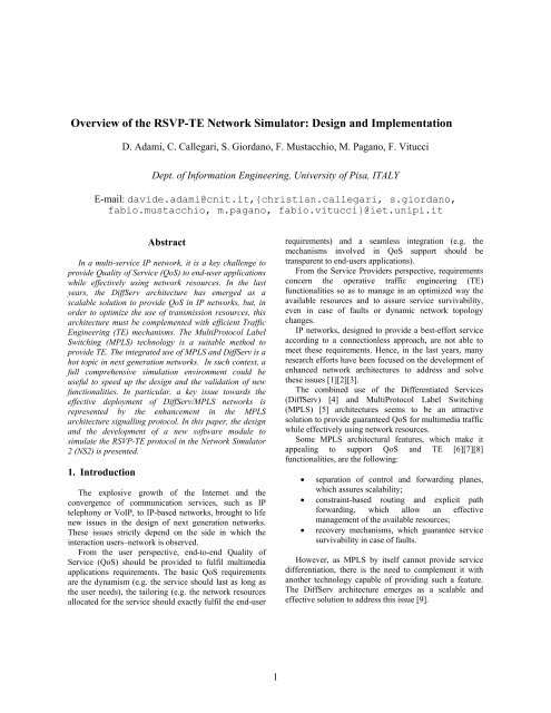
<strong>Overview</strong> <strong>of</strong> <strong>the</strong> <strong>RSVP</strong>-<strong>TE</strong> <strong>Network</strong> <strong>Simulator</strong>: <strong>Design</strong> <strong>and</strong> Implementation<br />
D. Adami, C. Callegari, S. Giordano, F. Mustacchio, M. Pagano, F. Vitucci<br />
Dept. <strong>of</strong> Information Engineering, University <strong>of</strong> Pisa, ITALY<br />
E-mail: davide.adami@cnit.it,{christian.callegari, s.giordano,<br />
fabio.mustacchio, m.pagano, fabio.vitucci}@iet.unipi.it<br />
Abstract<br />
In a multi-service IP network, it is a key challenge to<br />
provide Quality <strong>of</strong> Service (QoS) to end-user applications<br />
while effectively using network resources. In <strong>the</strong> last<br />
years, <strong>the</strong> DiffServ architecture has emerged as a<br />
scalable solution to provide QoS in IP networks, but, in<br />
order to optimize <strong>the</strong> use <strong>of</strong> transmission resources, this<br />
architecture must be complemented with efficient Traffic<br />
Engineering (<strong>TE</strong>) mechanisms. The MultiProtocol Label<br />
Switching (MPLS) technology is a suitable method to<br />
provide <strong>TE</strong>. The integrated use <strong>of</strong> MPLS <strong>and</strong> DiffServ is a<br />
hot topic in next generation networks. In such context, a<br />
full comprehensive simulation environment could be<br />
useful to speed up <strong>the</strong> design <strong>and</strong> <strong>the</strong> validation <strong>of</strong> new<br />
functionalities. In particular, a key issue towards <strong>the</strong><br />
effective deployment <strong>of</strong> DiffServ/MPLS networks is<br />
represented by <strong>the</strong> enhancement in <strong>the</strong> MPLS<br />
architecture signalling protocol. In this paper, <strong>the</strong> design<br />
<strong>and</strong> <strong>the</strong> development <strong>of</strong> a new s<strong>of</strong>tware module to<br />
simulate <strong>the</strong> <strong>RSVP</strong>-<strong>TE</strong> protocol in <strong>the</strong> <strong>Network</strong> <strong>Simulator</strong><br />
2 (NS2) is presented.<br />
1. Introduction<br />
The explosive growth <strong>of</strong> <strong>the</strong> Internet <strong>and</strong> <strong>the</strong><br />
convergence <strong>of</strong> communication services, such as IP<br />
telephony or VoIP, to IP-based networks, brought to life<br />
new issues in <strong>the</strong> design <strong>of</strong> next generation networks.<br />
These issues strictly depend on <strong>the</strong> side in which <strong>the</strong><br />
interaction users–network is observed.<br />
From <strong>the</strong> user perspective, end-to-end Quality <strong>of</strong><br />
Service (QoS) should be provided to fulfil multimedia<br />
applications requirements. The basic QoS requirements<br />
are <strong>the</strong> dynamism (e.g. <strong>the</strong> service should last as long as<br />
<strong>the</strong> user needs), <strong>the</strong> tailoring (e.g. <strong>the</strong> network resources<br />
allocated for <strong>the</strong> service should exactly fulfil <strong>the</strong> end-user<br />
1<br />
requirements) <strong>and</strong> a seamless integration (e.g. <strong>the</strong><br />
mechanisms involved in QoS support should be<br />
transparent to end-users applications).<br />
From <strong>the</strong> Service Providers perspective, requirements<br />
concern <strong>the</strong> operative traffic engineering (<strong>TE</strong>)<br />
functionalities so as to manage in an optimized way <strong>the</strong><br />
available resources <strong>and</strong> to assure service survivability,<br />
even in case <strong>of</strong> faults or dynamic network topology<br />
changes.<br />
IP networks, designed to provide a best-effort service<br />
according to a connectionless approach, are not able to<br />
meet <strong>the</strong>se requirements. Hence, in <strong>the</strong> last years, many<br />
research efforts have been focused on <strong>the</strong> development <strong>of</strong><br />
enhanced network architectures to address <strong>and</strong> solve<br />
<strong>the</strong>se issues [1][2][3].<br />
The combined use <strong>of</strong> <strong>the</strong> Differentiated Services<br />
(DiffServ) [4] <strong>and</strong> MultiProtocol Label Switching<br />
(MPLS) [5] architectures seems to be an attractive<br />
solution to provide guaranteed QoS for multimedia traffic<br />
while effectively using network resources.<br />
Some MPLS architectural features, which make it<br />
appealing to support QoS <strong>and</strong> <strong>TE</strong> [6][7][8]<br />
functionalities, are <strong>the</strong> following:<br />
• separation <strong>of</strong> control <strong>and</strong> forwarding planes,<br />
which assures scalability;<br />
• constraint-based routing <strong>and</strong> explicit path<br />
forwarding, which allow an effective<br />
management <strong>of</strong> <strong>the</strong> available resources;<br />
• recovery mechanisms, which guarantee service<br />
survivability in case <strong>of</strong> faults.<br />
However, as MPLS by itself cannot provide service<br />
differentiation, <strong>the</strong>re is <strong>the</strong> need to complement it with<br />
ano<strong>the</strong>r technology capable <strong>of</strong> providing such a feature.<br />
The DiffServ architecture emerges as a scalable <strong>and</strong><br />
effective solution to address this issue [9].
Since a framework has been defined to integrate<br />
MPLS <strong>and</strong> DiffServ technologies [10], this is an open<br />
research field <strong>and</strong> improved mechanisms towards a fully<br />
deployment <strong>of</strong> required functionalities have to be tested.<br />
In this scenario a simulation environment is useful to<br />
perform a functional assessment <strong>of</strong> <strong>the</strong> proposed<br />
approaches <strong>and</strong> to compare different solutions, reducing<br />
<strong>the</strong> complexity <strong>and</strong> <strong>the</strong> time needed to develop prototypal<br />
network devices.<br />
Unfortunately, a full comprehensive simulation<br />
environment for MPLS/DiffServ networks has not been<br />
developed yet. Therefore, our activity has been devoted to<br />
<strong>the</strong> implementation <strong>of</strong> s<strong>of</strong>tware modules that allow <strong>the</strong><br />
simulation <strong>of</strong> such a scenario. The starting point for our<br />
implementation is represented by <strong>the</strong> <strong>Network</strong> <strong>Simulator</strong><br />
version 2.26 (NS2) [11], along with <strong>the</strong> MPLS <strong>Network</strong><br />
<strong>Simulator</strong> version 2 (MNS) [12][13] <strong>and</strong> <strong>RSVP</strong> <strong>Network</strong><br />
<strong>Simulator</strong> (<strong>RSVP</strong>\ns) modules [14][15].<br />
The focus <strong>of</strong> <strong>the</strong> paper is on <strong>the</strong> implementation <strong>of</strong> a<br />
<strong>RSVP</strong>-<strong>TE</strong> protocol module, named <strong>RSVP</strong>-<strong>TE</strong>\ns, to be<br />
used as label distribution protocol in MNS. Indeed,<br />
<strong>RSVP</strong>-<strong>TE</strong> is <strong>the</strong> most commonly implemented signalling<br />
protocol in commercial routers <strong>and</strong> several research<br />
activities, as well as IETF working groups [16][17],<br />
address <strong>the</strong> issues related to <strong>the</strong> extensions <strong>of</strong> this<br />
protocol to support enhanced functionalities in<br />
MPLS/DiffServ networks. Moreover, several<br />
experimental test-beds, equipped both with Linux<br />
platforms <strong>and</strong> commercial routers, adopt this solution<br />
[18][19].<br />
The paper is organized as follows. Section 2 describes<br />
<strong>the</strong> MPLS node architecture in <strong>the</strong> NS2 environment,<br />
with emphasis on <strong>the</strong> <strong>RSVP</strong>-<strong>TE</strong> control plane<br />
characteristics. Section 3 discusses our implementation <strong>of</strong><br />
<strong>the</strong> <strong>RSVP</strong>-<strong>TE</strong>\ns module along with <strong>the</strong> LSP management<br />
functionalities available in <strong>the</strong> simulator. Section 4<br />
provides a description <strong>of</strong> <strong>the</strong> tests performed for a<br />
functional validation <strong>of</strong> <strong>the</strong> developed module. Section 5<br />
concludes <strong>the</strong> paper with some final remarks.<br />
2. MPLS node architecture<br />
The basic idea behind MPLS is to append a short<br />
fixed-length label to packets at <strong>the</strong> ingress router <strong>of</strong> an<br />
MPLS domain. Packet forwarding is <strong>the</strong>n based on <strong>the</strong><br />
assigned label <strong>and</strong> not on longest prefix address<br />
matching, as in traditional IP forwarding mechanisms.<br />
When a packet is received by an edge router <strong>of</strong> <strong>the</strong> MPLS<br />
domain, named Label Edge Router (LER), it is associated<br />
to a label on <strong>the</strong> basis <strong>of</strong> a Forwarding Equivalence Class<br />
(FEC). The packets associated to <strong>the</strong> same label traverse<br />
<strong>the</strong> MPLS network along <strong>the</strong> same path, identified as<br />
Label-Switched Path (LSP). Interior routers that perform<br />
label switching <strong>and</strong> label-based packet forwarding are<br />
called Label Switching Routers (LSRs).<br />
2<br />
In order to establish, maintain <strong>and</strong> tear-down LSPs a<br />
signalling protocol, such as <strong>the</strong> Label Distribution<br />
Protocol (LDP) or <strong>the</strong> <strong>RSVP</strong>-<strong>TE</strong> protocol, has to be used.<br />
An LDP implementation is integrated in <strong>the</strong> NS2 MNS<br />
module. Since <strong>RSVP</strong>-<strong>TE</strong> is widely deployed in<br />
experimental <strong>and</strong> working MPLS networks <strong>and</strong> several<br />
research activities are focused on enhancing such a<br />
protocol in an MPLS/DiffServ scenario, we decided to<br />
replace <strong>the</strong> CR-LDP signalling protocol module with our<br />
own implemented <strong>RSVP</strong>-<strong>TE</strong>\ns module. The reference<br />
model <strong>of</strong> an MPLS node is sketched in figure 1.<br />
Note that in <strong>the</strong> MNS implementation a strict<br />
distinction between control plane <strong>and</strong> forwarding<br />
functionalities can be found. Such a feature reflects <strong>the</strong><br />
separation between control <strong>and</strong> data planes in <strong>the</strong> MPLS<br />
architecture. For this reason, our work concerns only<br />
control plane mechanisms.<br />
<strong>RSVP</strong>-<strong>TE</strong><br />
Messages<br />
Routing<br />
Information<br />
Packets<br />
IN<br />
Control Plane<br />
Data Plane<br />
Routing Protocol<br />
Address Classifier<br />
Resource<br />
Manager<br />
<strong>RSVP</strong>-<strong>TE</strong><br />
MPLS Classifier Service Classifier<br />
Label<br />
Info<br />
Base<br />
Explicite<br />
Route<br />
Base<br />
Admission<br />
Control<br />
Packet Scheduler<br />
Packets<br />
OUT<br />
Figure 1. Reference model <strong>of</strong> an MPLS node<br />
In particular, in our simulator environment, labels<br />
distribution <strong>and</strong> allocation are performed by <strong>the</strong> <strong>RSVP</strong>-<strong>TE</strong><br />
agent we implemented. The agent supports downstream<br />
on dem<strong>and</strong> label allocation <strong>and</strong> upstream distribution.<br />
The <strong>RSVP</strong>-<strong>TE</strong> agent receives <strong>the</strong> labels by <strong>the</strong><br />
downstream LSRs <strong>and</strong> passes <strong>the</strong>m to <strong>the</strong> MPLS<br />
classifier, so that it can create <strong>the</strong> tables used for label<br />
switching.<br />
The data plane operations are <strong>the</strong> following: at first,<br />
when a packet is received by an LSR, <strong>the</strong> MPLS classifier<br />
checks if <strong>the</strong> packet is labelled. If <strong>the</strong> packet has a label<br />
or may be associated to an FEC, <strong>the</strong> MPLS classifier<br />
executes label-based forwarding, o<strong>the</strong>rwise it transfers<br />
<strong>the</strong> packet to <strong>the</strong> address classifier which forwards it<br />
according to <strong>the</strong> Layer 3 routing protocol.<br />
To perform label switching, an MPLS node in <strong>the</strong><br />
MNS implementation h<strong>and</strong>les three tables:<br />
• <strong>the</strong> Label Information Base (LIB), whose entries<br />
contain incoming label, incoming interface,<br />
outgoing label <strong>and</strong> outgoing interface;
• <strong>the</strong> Partial Forwarding Table (PFT), which<br />
contains a subset <strong>of</strong> <strong>the</strong> information written in<br />
<strong>the</strong> LIB;<br />
• <strong>the</strong> Explicit Route information Base (ERB),<br />
which contains information about <strong>the</strong> Explicit-<br />
Route LSP (ER-LSP).<br />
More in detail, when a labelled packet is received by<br />
an LSR, <strong>the</strong> node retrieves <strong>the</strong> incoming label, <strong>the</strong>n a<br />
table look up is performed to find <strong>the</strong> corresponding entry<br />
in <strong>the</strong> LIB. At this point, <strong>the</strong> LSR may execute two<br />
different operations. If it is an egress LER, it removes <strong>the</strong><br />
label from <strong>the</strong> packet <strong>and</strong> <strong>the</strong>n forwards it according to<br />
<strong>the</strong> Layer 3 routing protocol, passing it to <strong>the</strong> address<br />
classifier. Instead, if it is an LSR, it replaces <strong>the</strong> incoming<br />
label with <strong>the</strong> outgoing one (Label Swapping) <strong>and</strong> <strong>the</strong>n<br />
performs label-based forwarding.<br />
If <strong>the</strong> packet has to be forwarded on an explicit path,<br />
<strong>the</strong> MPLS node also uses <strong>the</strong> ERB, which is managed by<br />
<strong>the</strong> service classifier to map a flow into an ER-LSP.<br />
The PFT is used in packet forwarding only by <strong>the</strong><br />
ingress LER. In this case, <strong>the</strong> node receives an unlabelled<br />
packet <strong>and</strong> uses <strong>the</strong> PFT to associate a label to <strong>the</strong> packet<br />
itself, which is <strong>the</strong>n forwarded according to label<br />
switching mechanisms.<br />
The <strong>RSVP</strong>-<strong>TE</strong> agent we added in <strong>the</strong> MPLS node is<br />
able to perform two additional procedures: <strong>the</strong> Label<br />
Stacking <strong>and</strong> <strong>the</strong> Penultimate Hop Popping. The first one,<br />
which consists in managing multiple labels in a packet, is<br />
used to create a level <strong>of</strong> hierarchy in large networks,<br />
improving traffic flows scalability. Instead, Penultimate<br />
Hop Popping is used to simplify <strong>the</strong> operations executed<br />
on a labelled packet by <strong>the</strong> egress LER. This means that<br />
<strong>the</strong> penultimate LSR <strong>of</strong> <strong>the</strong> LSP executes label popping,<br />
instead <strong>of</strong> label swapping. Then it forwards an unlabelled<br />
packet towards <strong>the</strong> egress LER. To enable such a feature,<br />
<strong>the</strong> LIB contains additional information about <strong>the</strong><br />
operation <strong>the</strong> node has to execute for a specific LSP.<br />
Path Messages<br />
LIB<br />
ERB<br />
MPLS Node<br />
Link<br />
Admission<br />
Control<br />
Policing<br />
<strong>RSVP</strong>-<strong>TE</strong><br />
Resource<br />
Manager<br />
Packet Scheduler WFQ<br />
Resv Messages<br />
Figure 2. Resource reservation process<br />
3<br />
In order to support QoS, <strong>the</strong> developed module is also<br />
able to perform resource reservation for <strong>the</strong> LSP itself.<br />
The <strong>RSVP</strong>-<strong>TE</strong> agent is responsible for this action too.<br />
The resource reservation process, shown in figure 2, can<br />
be summarized as follows. When a Path message is<br />
received at <strong>the</strong> ingress interface <strong>of</strong> <strong>the</strong> LSR, <strong>the</strong> <strong>RSVP</strong>-<br />
<strong>TE</strong> agent performs Admission control <strong>and</strong> Policing<br />
functions. If <strong>the</strong>re are enough available resources it<br />
forwards <strong>the</strong> Path message to <strong>the</strong> downstream LSR.<br />
After Admission control <strong>and</strong> Policing operations have<br />
been performed all along <strong>the</strong> LSP, a Resv message is<br />
generated <strong>and</strong> forwarded upstream along <strong>the</strong> LSP. An<br />
LSR, when processing a Resv message, allocates<br />
resources <strong>and</strong> calls <strong>the</strong> resource manager to properly<br />
configure <strong>the</strong> queues in <strong>the</strong> packet scheduler. The<br />
scheduler used with <strong>the</strong> <strong>RSVP</strong>-<strong>TE</strong> module is <strong>the</strong><br />
Weighted Fair Queuing (WFQ), which is already<br />
implemented in NS2. Moreover, <strong>the</strong> <strong>RSVP</strong>-<strong>TE</strong> agent calls<br />
<strong>the</strong> MPLS classifier to create <strong>the</strong> corresponding entries in<br />
<strong>the</strong> LIB <strong>and</strong> PFT tables used for label switching.<br />
3. <strong>RSVP</strong>-<strong>TE</strong>\ns module<br />
In this section, we illustrate <strong>the</strong> main functionalities <strong>of</strong><br />
<strong>the</strong> developed module. <strong>RSVP</strong>-<strong>TE</strong>\ns has been<br />
implemented in compliance with <strong>the</strong> st<strong>and</strong>ard defined in<br />
[20].<br />
The simulator functionalities can be divided in two<br />
distinct sets:<br />
• <strong>the</strong> first one (see section 3.1) concerns LSPs<br />
establishment;<br />
• <strong>the</strong> second one (see section 3.2) is about LSPs<br />
tear-down.<br />
3.1. LSP Establishment<br />
Two different comm<strong>and</strong>s may be used to establish an<br />
LSP: <strong>the</strong> first one is used when <strong>the</strong> ingress LER wants to<br />
establish an ER-LSP, while <strong>the</strong> second one is used when<br />
it wants to create an ER-LSP with a reserved b<strong>and</strong>width.<br />
create-erlsp-rsvpte<br />
<br />
<br />
create-erbwlsp-rsvpte<br />
<br />
<br />
In both cases, <strong>the</strong> Path message sent by <strong>the</strong> ingress<br />
LER contains, in addition to <strong>the</strong> classical <strong>RSVP</strong> objects, a<br />
LABEL_REQUEST object, used for requesting to <strong>the</strong><br />
downstream nodes <strong>the</strong> allocation <strong>of</strong> <strong>the</strong> labels.<br />
The simulator allows to create an LSP that follows an<br />
explicit path by specifying in <strong>the</strong> option a sequence
<strong>of</strong> nodes addresses. This field, if not empty, is used to<br />
create an EXPLICIT_ROU<strong>TE</strong>_OBJECT (ERO), which is<br />
added to <strong>the</strong> Path message.<br />
When an LSR receives a Path message, it performs<br />
several operations; <strong>the</strong> first ones are related to admission<br />
control <strong>and</strong> policing. Then <strong>the</strong> node processes <strong>the</strong> ERO: it<br />
inserts <strong>the</strong> ERO contents in its Path State Block (PSB)<br />
<strong>and</strong> <strong>the</strong>n it looks for <strong>the</strong> next abstract node, to forward <strong>the</strong><br />
Path message to. The insertion <strong>of</strong> <strong>the</strong> ERO value in <strong>the</strong><br />
PSB is needed in order to assure that Resv messages<br />
follow, in <strong>the</strong> upstream direction, <strong>the</strong> same route <strong>of</strong> <strong>the</strong><br />
Path ones. Once <strong>the</strong> egress LER has received <strong>and</strong><br />
processed <strong>the</strong> Path message, it generates a Resv message<br />
that contains, in <strong>the</strong> LABEL object, <strong>the</strong> label value to be<br />
used by <strong>the</strong> upstream node.<br />
When an LSR receives <strong>the</strong> Resv message, <strong>the</strong> node<br />
sets a new label value to be suggested to <strong>the</strong> upstream<br />
node. Moreover, if <strong>the</strong> issued comm<strong>and</strong> is for an ER-LSP<br />
with b<strong>and</strong>width reservation, <strong>the</strong> LSR calls <strong>the</strong> Resource<br />
manager which, in turn, executes <strong>the</strong> resource allocation<br />
Subsequently, it passes <strong>the</strong> label contained in <strong>the</strong> Resv<br />
message (outgoing label) <strong>and</strong> <strong>the</strong> new label (incoming<br />
label) to <strong>the</strong> MPLS classifier, which uses <strong>the</strong>m to create<br />
<strong>the</strong> corresponding entry in <strong>the</strong> label switching tables.<br />
Finally, <strong>the</strong> LSR generates a Resv message, with a<br />
LABEL object containing <strong>the</strong> value <strong>of</strong> <strong>the</strong> suggested<br />
label, <strong>and</strong> forwards it to <strong>the</strong> previous node as stored in <strong>the</strong><br />
PSB.<br />
When <strong>the</strong> ingress LER processes <strong>the</strong> Resv message <strong>the</strong><br />
LSP is established. Ano<strong>the</strong>r comm<strong>and</strong> may be used to<br />
bind a flow to <strong>the</strong> LSP.<br />
3.2. LSP Tear down<br />
The second set <strong>of</strong> functionalities allows to tear down<br />
an LSP when a failure occurs. The following comm<strong>and</strong><br />
drives <strong>the</strong> simulation <strong>of</strong> a link failure<br />
break-link <br />
The following subsequent actions, related to <strong>the</strong><br />
h<strong>and</strong>ling <strong>of</strong> this event, are automatically performed:<br />
• <strong>the</strong> link between <strong>the</strong> <br />
<strong>and</strong> <strong>the</strong> fails;<br />
• <strong>the</strong> rsvp-agent <strong>of</strong> <strong>the</strong> <br />
sends, for each LSP that is established on <strong>the</strong><br />
broken link, a PathErr message upstream, so as<br />
to notify <strong>the</strong> ingress LER <strong>of</strong> <strong>the</strong> failure;<br />
• <strong>the</strong> rsvp-agent <strong>of</strong> <strong>the</strong> <br />
sends, for each LSP that is established on <strong>the</strong><br />
broken link, a ResvErr message downstream, so<br />
as to notify <strong>the</strong> egress LSR <strong>of</strong> <strong>the</strong> failure;<br />
4<br />
• <strong>the</strong> egress LSR, after processing each ResvErr<br />
message, sends to <strong>the</strong> <br />
a ResvTear message, in order to release <strong>the</strong><br />
previously allocated resources;<br />
• <strong>the</strong> ingress LER, after processing each PathErr<br />
message, sends to <strong>the</strong> a<br />
PathTear message, in order to release <strong>the</strong><br />
previously allocated resources;<br />
• <strong>the</strong> ingress LER delete <strong>the</strong> corresponding entry<br />
in <strong>the</strong> LIB, PFT <strong>and</strong> ERB tables.<br />
After <strong>the</strong>se operations, all <strong>the</strong> flows bound to an LSP<br />
that has been torn down are forwarded according to a<br />
Layer 3 routing protocol. This allows applying different<br />
rerouting techniques.<br />
4. Functional validation tests<br />
In this section we present some <strong>of</strong> <strong>the</strong> tests carried out<br />
to validate <strong>the</strong> new functionalities added to <strong>the</strong> simulator.<br />
The network topology (figure 3) is quite simple, but<br />
appropriate to highlight <strong>the</strong> most important functionalities<br />
<strong>of</strong> <strong>RSVP</strong>-<strong>TE</strong>\ns.<br />
0<br />
2<br />
2<br />
0<br />
2<br />
3<br />
10<br />
0<br />
2<br />
1<br />
9<br />
1<br />
11<br />
0<br />
1<br />
Figure 3: <strong>Network</strong> topology<br />
In this network scenario, nodes 3-11 are MPLSenabled,<br />
whereas nodes 0, 1 <strong>and</strong> 2 act as traffic sources,<br />
that send a data traffic stream to <strong>the</strong> nodes 12, 13 <strong>and</strong> 14<br />
respectively. Moreover, <strong>the</strong> b<strong>and</strong>width assigned to each<br />
link is 1 Mbps.<br />
In figures 3-9, <strong>the</strong> packets belonging to each flow are<br />
identified by <strong>the</strong> source node number.<br />
The first test is performed to verify <strong>the</strong> resources<br />
allocation mechanism along an LSP.<br />
A Constant Bit Rate (CBR) data traffic at 400 Kbps is<br />
generated by <strong>the</strong> node 2 <strong>and</strong> received by <strong>the</strong> node 14; <strong>the</strong><br />
links 11_4 <strong>and</strong> 4_5 are congested due to <strong>the</strong> traffic<br />
generated by <strong>the</strong> nodes 0 <strong>and</strong> 1.<br />
According to <strong>the</strong> Layer 3 routing protocol (OSPF) all<br />
<strong>the</strong> flows are forwarded along <strong>the</strong> same path, so that each<br />
flow experiments packet losses on <strong>the</strong> congested links.<br />
8<br />
0<br />
4<br />
2<br />
1<br />
7<br />
5<br />
1<br />
0<br />
6<br />
12<br />
2<br />
13<br />
14
Indeed, as shown in figure 4, <strong>the</strong> throughput <strong>of</strong> <strong>the</strong><br />
flow 2 is about 200 Kbps when no LSP is established. An<br />
LSP is <strong>the</strong>n set-up (t=46 sec) with a reserved b<strong>and</strong>width<br />
equal to 400 Kbps, between <strong>the</strong> nodes 10 <strong>and</strong> 5. The<br />
binding <strong>of</strong> <strong>the</strong> flow to <strong>the</strong> LSP is completed at 50.0<br />
seconds <strong>and</strong> <strong>the</strong> throughput rises at 400 Kbps as a<br />
consequence <strong>of</strong> a proper resource allocation process.<br />
Figure 4: Flow rate (src 2) on link 4_5<br />
The second test is performed to assess label<br />
distribution <strong>and</strong> fault recovery functionalities. The<br />
network topology is <strong>the</strong> same as in <strong>the</strong> previous test <strong>and</strong><br />
all <strong>the</strong> sources generate CBR traffic at 400Kbps.<br />
After 5.0 seconds <strong>of</strong> simulation, three ER-LSP are<br />
established:<br />
• LSP0 includes nodes 3, 10, 9, 8, 7, 6, 5 <strong>and</strong> it is<br />
associated to flow 0;<br />
• LSP1 includes nodes 11, 4, 5 <strong>and</strong> it is associated<br />
to flow 1;<br />
• LSP2 includes nodes 3, 10, 9, 8, 7, 5 <strong>and</strong> it is<br />
associated to flow 2.<br />
0<br />
2<br />
2<br />
0<br />
3<br />
2<br />
10<br />
2<br />
1<br />
0<br />
9<br />
1<br />
11<br />
2 0<br />
Path Message<br />
1<br />
Figure 5: Path message for flow from 2 to 14<br />
8<br />
2<br />
4<br />
0<br />
7<br />
1<br />
5<br />
2<br />
6<br />
0<br />
1<br />
12<br />
13<br />
14<br />
5<br />
In figure 5 <strong>the</strong> Path message for <strong>the</strong> ER-LSP<br />
establishment through 3, 10, 9, 8, 7, 6, 5 nodes is shown.<br />
At 8.0 seconds <strong>the</strong> binding <strong>of</strong> <strong>the</strong> flows to <strong>the</strong> LSP is<br />
completed <strong>and</strong> <strong>the</strong> flows are forwarded according to label<br />
switching (figure 6).<br />
The subsequent phase aims at testing <strong>the</strong> fault<br />
notification mechanisms. In order to test this aspect, a<br />
fault is forced on <strong>the</strong> link 7_5, so that node 7 sends a<br />
PathErr message (figure 7).<br />
0 0<br />
0<br />
2<br />
2<br />
2<br />
2<br />
0<br />
2<br />
3<br />
3<br />
10<br />
0<br />
0<br />
0<br />
10<br />
0<br />
2<br />
1<br />
0<br />
9<br />
11<br />
0<br />
Figure 6: Label switching<br />
2<br />
1<br />
1<br />
1<br />
2<br />
1<br />
1<br />
11<br />
0 2 0<br />
9<br />
Figure 7: Failure <strong>and</strong> PathErr message<br />
After receiving <strong>the</strong> PathErr message, node 10 sends a<br />
PathTear message downstream to release <strong>the</strong> previously<br />
allocated resources <strong>and</strong> to delete <strong>the</strong> label switching table<br />
entries associated to <strong>the</strong> LSP. As a consequence, flow<br />
from node 2 to node 14 is now forwarded according to<br />
<strong>the</strong> Layer 3 routing protocol, as shown in figure 8.<br />
Figure 9 shows <strong>the</strong> throughput at node 14.<br />
From t = 15 seconds to t = 15.6 seconds, no packet is<br />
received. Then, traffic flows are forwarded according to<br />
Layer 3 routing protocol. No decrease in <strong>the</strong> received<br />
throughput can be observed, since no congestion occurs<br />
along <strong>the</strong> new path.<br />
8<br />
8<br />
2<br />
4<br />
1<br />
4<br />
2<br />
1<br />
0<br />
0<br />
7<br />
7<br />
2<br />
5<br />
0<br />
0<br />
1<br />
5<br />
2<br />
0<br />
0<br />
1<br />
6<br />
6<br />
0<br />
PathErr Message<br />
0<br />
2<br />
12<br />
13<br />
14<br />
1<br />
13<br />
12<br />
14
0<br />
2<br />
2<br />
0<br />
3<br />
2<br />
10<br />
Figure 8: Situation after link failure<br />
Figure 9: Flow rate (src 2) on link 5_14<br />
Finally, we assess <strong>the</strong> simulator behaviour, when a<br />
link, on which several LSPs are established, fails. In order<br />
to test this aspect, a link failure is forced on link 6_7. As<br />
supposed, nodes 7 <strong>and</strong> 5 send respectively a PathErr <strong>and</strong><br />
a ResvErr message. After processing <strong>the</strong> corresponding<br />
PathTear <strong>and</strong> ResvTear messages, <strong>the</strong> two LSPs (which<br />
are established on <strong>the</strong> broken link) are released <strong>and</strong> <strong>the</strong><br />
corresponding flows are, once again, forwarded<br />
according to <strong>the</strong> Layer 3 routing protocol.<br />
5. Conclusions<br />
0<br />
1<br />
0<br />
1<br />
11<br />
2<br />
9<br />
0<br />
1<br />
In this paper, we discuss <strong>the</strong> development <strong>and</strong> validate<br />
<strong>the</strong> functionalities <strong>of</strong> a new s<strong>of</strong>tware module that<br />
implements <strong>the</strong> <strong>RSVP</strong>-<strong>TE</strong> signalling protocol in <strong>the</strong> NS2<br />
simulation tool. The new module provides a complete<br />
implementation <strong>of</strong> <strong>the</strong> control plane mechanisms needed<br />
for label distribution <strong>and</strong> label binding as well as link<br />
failure h<strong>and</strong>ling in MPLS networks. It is relevant to<br />
emphasize that this module has been developed taking<br />
into account extensibility <strong>and</strong> flexibility issues, so that<br />
enhancements to <strong>the</strong> signalling protocol (i.e. definition <strong>of</strong><br />
new objects) could be easily introduced. Hence, <strong>the</strong><br />
8<br />
2<br />
4<br />
0<br />
7<br />
1<br />
2<br />
5<br />
0<br />
0<br />
6<br />
0<br />
1<br />
12<br />
13<br />
14<br />
6<br />
module we implemented could be useful to plan <strong>and</strong><br />
assess new functionalities in MPLS/DiffServ or GMPLS<br />
networks.<br />
6. Acknowledgments<br />
This work was partially supported by <strong>the</strong> Euro-NGI<br />
<strong>Network</strong> <strong>of</strong> Excellence funded by <strong>the</strong> European<br />
Commission<br />
References<br />
[1] X. Xiao, L.M. Ni, Internet QoS: A Big Picture, IEEE <strong>Network</strong><br />
Magazine, March 1999<br />
[2] Trimintzios, P. Andrikopoulos, I. Pavlou, G. Flegkas, P. Griffin, D.<br />
Georgatsos, P. Goderis, D. T'Joens, Y. Georgiadis, L. Jacquenet,<br />
C.; Egan, R., A management <strong>and</strong> control architecture for providing<br />
IP Differentiated Services in MPLS-based <strong>Network</strong>s, IEEE<br />
Communications Magazine, May 2001<br />
[3] Engel, T. Granzer, H. Koch, B.F. Winter, M. Sampatakos, P.;<br />
Venieris, I.S. Hussmann, H. Ricciato, F. Salsano, S., AQUILA:<br />
Adaptive resource control for QoS using an IP-based layered<br />
architecture, IEEE Communications Magazine, January 2003<br />
[4] S. Blake, D. Black, M. Carlson, E. Davies, Z. Wang, W. Weiss.,<br />
An Architecture for Differentiated Services, IETF RFC 2475,<br />
December 1998<br />
[5] E. Rosen, A. Viswanathan, R. Callon., Multiprotocol Label<br />
Switching Architecture, IETF RFC 3031, January 2001<br />
[6] D. Awduche, J. Malcolm, J. Agogbua, M. O'Dell, J. McManus.,<br />
Requirements for Traffic Engineering over MPLS, IETF RFC 2702,<br />
September 1999<br />
[7] G. Swallow MPLS Advantages for Traffic Engineering, IEEE<br />
Communications Magazine, December 1999<br />
[8] X. Xiao, A. Hannan, B. Bailey, L. Ni, Traffic engineering with<br />
MPLS in <strong>the</strong> Internet, IEEE <strong>Network</strong> Magazine, March 2000.<br />
[9] B. Carpenter, K. Nichols Differentiated Services in <strong>the</strong> Internet,<br />
Proceedings <strong>of</strong> <strong>the</strong> IEEE, September 2002<br />
[10] F. Le Faucheur, L. Wu, B. Davie, S. Davari, P. Vaananen, R.<br />
Krishnan, P. Cheval, J. Heinanen, MPLS support <strong>of</strong> Differentiated<br />
Services, IETF RFC 3270, May 2002<br />
[11] The <strong>Network</strong> <strong>Simulator</strong> vers.2.26 (NS2) Home Page<br />
www.isi.edu/nsnam/dist/<br />
[12] The MPLS <strong>Network</strong> <strong>Simulator</strong> version 2 Home Page<br />
http://flower.ce.cnu.ac.kr/~fog1/mns/<br />
[13] G. Ahn, W. Chun <strong>Design</strong> <strong>and</strong> Implementation <strong>of</strong> MPLS <strong>Network</strong><br />
<strong>Simulator</strong> (MNS) Supporting QoS, ICOIN- 2001<br />
[14] The <strong>RSVP</strong> module for NS2 Home Page http://titan.cs.unibonn.de/~greis/rsvpns<br />
index.html<br />
[15] M. Greis <strong>RSVP</strong>\ns: An Implementation <strong>of</strong> <strong>RSVP</strong> for <strong>the</strong> <strong>Network</strong><br />
<strong>Simulator</strong> ns-2<br />
[16] IETF MPLS WG http://www.ietf.org/html.charters/mplscharter.html<br />
[17] IETF CCAMP Working Group<br />
http://www.ietf.org/html.charters/ccamp-charter.html<br />
[18] G. Carrozzo, N. Ciulli, S. Giordano, G. Giorgi, M. Listanti, U.<br />
Monaco, F. Mustacchio, G. Procissi, F. Ricciato,. Architecture <strong>and</strong><br />
protocols for <strong>the</strong> seamless <strong>and</strong> integrated next generation IP<br />
networks, QoS-IP 2005<br />
[19] D. Adami, N. Carlotti, S. Giordano, M. Pagano, M. Repeti,<br />
Performance analysis <strong>of</strong> <strong>the</strong> Control <strong>and</strong> Forwarding plane in a<br />
MPLS router, OpNeTec 2004<br />
[20] D. Awduche, L. Berger, D. Gan, T. Li, V. Srinivasan, G. Swallowl.<br />
<strong>RSVP</strong>-<strong>TE</strong>: Extensions to <strong>RSVP</strong> for LSP Tunnels, IETF RFC 3209,<br />
December 2001