ABB industrial drives - ACS880, single drives, 0.55 to 250 ... - Auser
ABB industrial drives - ACS880, single drives, 0.55 to 250 ... - Auser
ABB industrial drives - ACS880, single drives, 0.55 to 250 ... - Auser

Create successful ePaper yourself
Turn your PDF publications into a flip-book with our unique Google optimized e-Paper software.
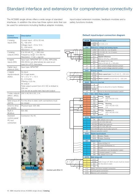
Standard interface and extensions for comprehensive connectivity<br />
The <strong>ACS880</strong> <strong>single</strong> <strong>drives</strong> offers a wide range of standard<br />
interfaces. In addition the drive has three option slots that can<br />
be used for extensions including fieldbus adapter modules,<br />
Control<br />
connections<br />
2 analog<br />
inputs (XAI)<br />
2 analog<br />
outputs (XAO)<br />
6 digital<br />
inputs (XDI)<br />
Digital input<br />
interlock (DIIL)<br />
2 digital<br />
inputs/outputs<br />
(XDIO)<br />
3 relay outputs<br />
(XRO1, XRO2,<br />
XRO3)<br />
Safe <strong>to</strong>rque-off<br />
(XSTO)<br />
Drive-<strong>to</strong>-drive<br />
link (XD2D)<br />
Built-in<br />
Modbus<br />
Assistant<br />
control panel/<br />
PC <strong>to</strong>ol<br />
connection<br />
Description<br />
Current input: –20 <strong>to</strong> 20 mA,<br />
R in : 100 ohm<br />
Voltage input: –10 <strong>to</strong> 10 V,<br />
R in : 200 kohm<br />
Resolution: 11 bit + sign bit<br />
0 <strong>to</strong> 20 mA, R load < 500 ohm<br />
Frequency range: 0 <strong>to</strong> 300 Hz<br />
Resolution: 11 bit + sign bit<br />
Input type: NPN/PNP (DI1 <strong>to</strong> DI5), NPN (DI6)<br />
DI6 (XDI:6) can alternatively be used as an<br />
input for a PTC thermis<strong>to</strong>r.<br />
Input type: NPN/PNP<br />
As input:<br />
24 V logic levels:<br />
“0” < 5 V, “1” > 15 V<br />
R in : 2.0 kohm<br />
Filtering: 0.25 ms<br />
As output:<br />
Total output current from 24 V DC is limited <strong>to</strong><br />
200 mA<br />
Can be set as pulse train input and output<br />
<strong>250</strong> V AC/30 V DC, 2 A<br />
For the drive <strong>to</strong> start, both connections must<br />
be closed<br />
Physical layer: EIA-485<br />
EIA-485<br />
Connec<strong>to</strong>r: RJ-45<br />
16 <strong>ABB</strong> <strong>industrial</strong> <strong>drives</strong> <strong>ACS880</strong> <strong>single</strong> <strong>drives</strong> | Catalog<br />
Control unit ZCU-11<br />
input/output extension modules, feedback modules and a<br />
safety functions module.<br />
Fault<br />
Default input/output connection diagram<br />
XPOW External power input<br />
1<br />
2<br />
+24VI<br />
GND<br />
24 V DC, 2 A<br />
XAI Reference voltage and analog inputs<br />
1 +VREF 10 V DC, RL 1 <strong>to</strong> 10 kohm<br />
2 -VREF -10 V DC, RL 1 <strong>to</strong> 10 kohm<br />
3 AGND Ground<br />
4 AI1+ Speed reference<br />
5 AI1- 0(2) <strong>to</strong> 10 V, R > 200 kohm<br />
in<br />
6 AI2+ By default not in use.<br />
7 AI2- 0(4) <strong>to</strong> 20 mA, R > 100 ohm<br />
in<br />
J1 J1 AI1 current/voltage selection jumper<br />
J2 J2 AI2 current/voltage selection jumper<br />
XAO Analog outputs<br />
1<br />
2<br />
AO1<br />
AGND<br />
Mo<strong>to</strong>r speed rpm 0 <strong>to</strong> 20 mA, R < 500 ohm<br />
L<br />
3<br />
4<br />
AO2<br />
AGND<br />
Mo<strong>to</strong>r current 0 <strong>to</strong> 20 mA, R < 500 ohm<br />
L<br />
XD2D Drive-<strong>to</strong>-drive link<br />
1 B<br />
2 A Drive-<strong>to</strong>-drive link or built-in Modbus<br />
3 BGND<br />
J3 J3 Drive-<strong>to</strong>-drive link termination switch<br />
XRO1, XRO2, XRO3 Relay outputs<br />
1 NC Ready<br />
2 COM<br />
<strong>250</strong> V AC/30 V DC<br />
3 NO<br />
2 A<br />
1 NC Running<br />
2 COM<br />
<strong>250</strong> V AC/30 V DC<br />
3 NO<br />
2 A<br />
1 NC Faulted (-1)<br />
2 COM<br />
<strong>250</strong> V AC/30 V DC<br />
3 NO<br />
2 A<br />
XD24 Digital interlock<br />
1 DIIL By default not in use<br />
2 +24VD +24 V DC 200 mA<br />
3 DICOM Digital input ground<br />
4 +24VD +24 V DC 200 mA<br />
5 DIOGND Digital input/output ground<br />
J6 Ground selection switch<br />
XDIO Digital input/outputs<br />
1 DIO1 Output: Ready<br />
2 DIO2 Output: Running<br />
XDI Digital inputs<br />
1 DI1 S<strong>to</strong>p (0)/Start (1)<br />
2 DI2 Forward (0)/Reverse (1)<br />
3 DI3 Reset<br />
4 DI4 Acceleration and deceleration select<br />
5 DI5 Constant speed 1 (1=On)<br />
6 DI6 By default not in use<br />
XSTO Safe <strong>to</strong>rque-off<br />
1 OUT1<br />
2 SGND Safe <strong>to</strong>rque-off. Both circuits must be closed<br />
3 IN1 for the drive <strong>to</strong> start.<br />
4 IN2<br />
X12 Safety functions module connection<br />
X13 Control panel connection<br />
X205 Memory unit connection