Coordinated Facility Protection Catalog - Erico
Coordinated Facility Protection Catalog - Erico
Coordinated Facility Protection Catalog - Erico

You also want an ePaper? Increase the reach of your titles
YUMPU automatically turns print PDFs into web optimized ePapers that Google loves.
<strong>Coordinated</strong> <strong>Facility</strong><br />
<strong>Protection</strong><br />
Selecting Surge <strong>Protection</strong>
Introduction .............................................................................................................................. 3<br />
The Need for <strong>Coordinated</strong> <strong>Protection</strong> ................................................................................. 4-5<br />
Selecting Surge <strong>Protection</strong> ................................................................................................... 6-7<br />
A Guide to Common Power Distribution Systems ........................................................... 8-11<br />
Data and Signal Line <strong>Protection</strong> ...................................................................................... 12-14<br />
Surge <strong>Protection</strong> And Surge Ratings .................................................................................... 15<br />
Advanced Technologies – The ERICO Advantage ................................................................ 16<br />
Glossary of Terminology ................................................................................................... 17-18<br />
Electrical Power <strong>Protection</strong><br />
Panelboard Mount<br />
Service Entrance Suppression ............................................................................................ 19-20<br />
Transient Discriminating Service Entrance Suppressor ........................................................ 21-22<br />
Transient Discriminating Panel <strong>Protection</strong> .......................................................................... 23-31<br />
Transient Discriminating MOVTEC <strong>Protection</strong> Module ............................................................ 32<br />
Transient Discriminating MOVTEC .......................................................................................... 33<br />
DIN Rail Mount Diverters<br />
Triggered Spark Gap .............................................................................................................. 34<br />
Spark Gap Diverter ................................................................................................................ 35<br />
TDS Surge Diverter ........................................................................................................... 36-40<br />
TDS Surge Diverter – Photovoltaic .......................................................................................... 41<br />
Dinline Surge Diverter ....................................................................................................... 42-50<br />
DIN Rail Mount Filters<br />
Dinline Surge Filter ................................................................................................................ 51<br />
Transient Discriminating Filter ........................................................................................... 52-53<br />
Surge Reductions Filters<br />
TSG-SRF ........................................................................................................................... 54-55<br />
Data, Control, Signal Line <strong>Protection</strong><br />
Data & Signal Line <strong>Protection</strong><br />
Universal Transient Barrier ................................................................................................. 56-60<br />
Remote Transmitter Protector ................................................................................................ 61<br />
Loadcell Protector .................................................................................................................. 62<br />
Telecommunications<br />
Subscriber Line / High Speed Data Line <strong>Protection</strong> .................................................................. 63<br />
RJ11 Telephone Line <strong>Protection</strong> .............................................................................................. 64<br />
Communication<br />
Data Equipment <strong>Protection</strong> .................................................................................................... 65<br />
Local Area Network <strong>Protection</strong> .............................................................................................. 66<br />
Coaxial<br />
Community Antenna and Closed Circuit Television <strong>Protection</strong> ................................................ 67<br />
Coaxial Surge <strong>Protection</strong> ........................................................................................................ 68<br />
Special Application Products<br />
MWE - Outdoor Weatherproof Enclosures ........................................................................ 69-72<br />
Potential Equalization Clamp ................................................................................................. 73<br />
DINLINE Decoupling Inductor/ DINLINE Alarm Relay & Surge Counter ..................................... 74<br />
MGA Tester ........................................................................................................................... 75<br />
2<br />
www.erico.com
Introduction<br />
By following the Six Point Plan of <strong>Protection</strong>, ERICO<br />
customers are able to implement the most effective<br />
solutions to individual lightning, grounding and surge<br />
problems while retaining an integrated protection<br />
philosophy.<br />
Point 5 of the Six Point Plan advocates a coordinated<br />
approach to surge protection, where the fi rst stage of<br />
defense is the installation of primary protection devices at<br />
the mains supply service entrance, followed by secondary<br />
protection at distribution branch panels and where<br />
necessary, at point-of-use applications.<br />
Point 6 recognizes the need to provide effective surge<br />
protection on cables supplying telecommunications,<br />
signal and data management equipment.<br />
Overhead<br />
Distribution<br />
Voltage<br />
Transmission<br />
Lines<br />
Direct Lightning Strike<br />
Telephone Lines<br />
AC Transformer<br />
Sub Station<br />
Power Ground<br />
Protect Low Voltage<br />
Data/Telecommunications<br />
Circuits<br />
PCS,<br />
Radio &<br />
Telemetry<br />
Equipment<br />
Capture the<br />
lightning<br />
strike<br />
Telephone Main<br />
Distribution<br />
Frame<br />
Power<br />
Distribution Panel<br />
Protect<br />
Incoming AC<br />
Power Feeders<br />
Safely Convey<br />
Energy to<br />
Ground<br />
Low Impedance Ground<br />
using fl at copper radials<br />
Ground Enhancement<br />
Material<br />
ERITECH ® SYSTEM 2000<br />
Conventional Lightning<br />
<strong>Protection</strong> System<br />
Inverter<br />
Rectifi er<br />
Inspection Well<br />
Ground Potential<br />
Equalization Bonding<br />
Dissipate Energy<br />
into the<br />
Grounding<br />
System<br />
www.erico.com 3<br />
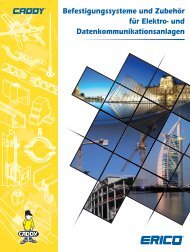
The Six Point Plan of <strong>Protection</strong> from ERICO<br />
Capture the lightning strike.<br />
Capture the lightning strike to a known and preferred attachment point using a<br />
purpose-designed air terminal system.<br />
Convey this energy to ground.<br />
Conduct the energy to the ground via a purpose-designed downconductor.<br />
Dissipate the energy into the grounding system.<br />
Dissipate the energy into a low impedance grounding system.<br />
Bond all ground points together.<br />
Bond all ground points to eliminate ground loops and create an equipotential<br />
plane.<br />
Protect incoming AC power feeders.<br />
Protect equipment from surges and transients on incoming power lines to prevent<br />
equipment damage and costly operational downtime.<br />
Protect low voltage data/telecommunications circuits.<br />
Protect equipment from surges and transients on incoming telecommunications<br />
and signal lines to prevent equipment damage and costly operational downtime.<br />
PABX<br />
Batteries<br />
IS<br />
File<br />
Server<br />
Billing Printer<br />
Computer<br />
Bond All<br />
Ground Points<br />
Together<br />
SPD<br />
Sub-Distribution<br />
Board<br />
Remote<br />
Data<br />
Terminal<br />
ERITECH ® SYSTEM 3000<br />
Active Lightning<br />
<strong>Protection</strong> System<br />
Induced Surge<br />
Signal Control<br />
Lines<br />
Surge <strong>Protection</strong> Device<br />
Communications Line <strong>Protection</strong> Device<br />
Ground Electrode
The Need for <strong>Coordinated</strong> <strong>Protection</strong><br />
Critical Factors<br />
Critical factors need to be considered when determining the need for facility<br />
protection. Many factors can be determined by answering the following<br />
questions:<br />
• What is the risk to personnel?<br />
• What is the risk of equipment damage?<br />
• What are the consequences of equipment failure?<br />
• Is the equipment associated with an essential service?<br />
• How will equipment failure affect overall facility operation and revenue<br />
generation?<br />
• What are the legal implications of providing inadequate protection?<br />
The statistical nature of lightning and the broad spectrum of energy delivered<br />
by a lightning fl ash, the problems created by various power generation and<br />
distribution systems, and the continued trend to more sensitive and specialized<br />
electronics, requires careful selection of available technologies if adequate<br />
protection is to be provided.<br />
What are the costs of inadequate protection?<br />
The costs that can result from inadequate protection<br />
are many and varied. The type of equipment within a<br />
facility will have a direct impact on the damage that<br />
can occur. Robust equipment, such as lighting and<br />
air-conditioning systems, are often able to withstand<br />
impulses as high as 1500 volts and are not as sensitive<br />
to the rapid rate-of-rise exhibited by the pre-clamped<br />
surge waveform as are electronics. These systems are<br />
often not critical to the continuing operation of the site<br />
and therefore usually do not require the premium level<br />
of protection that is essential for more sensitive<br />
equipment.<br />
However, signifi cant damage can occur, even to the<br />
more robust systems, as a result of lightning induced<br />
surges resulting within a radius of several kilometers,<br />
or from switching induced surges.<br />
Costs can range from degradation of electrical or<br />
electronic systems to data loss, equipment destruction<br />
or injury to personnel. Some of these costs can appear<br />
relatively minor but the loss of an essential service or<br />
revenues associated with a facility or plant shut down<br />
can be enormous.<br />
Damage to vital equipment caused<br />
by destructive surges and transients.<br />
4<br />
Sources of Transients and Surges<br />
Although lightning is the most spectacular form of<br />
externally generated surges, it is only one source of<br />
over-voltage. Other sources include the switching of<br />
power circuits, the operation of electrical equipment by<br />
neighboring industries, the operation of power factor<br />
correction devices, and the switching and clearing of<br />
faults on transmission lines. It is important to note that<br />
lightning does not need to directly strike a power line for<br />
such damage to occur; a strike several hundred meters<br />
away can induce large damaging transients, even to<br />
underground cables.<br />
It is estimated that 70 to 85% of all transients are<br />
generated internally within one’s own facility by the<br />
switching of electrical loads such as lights, heating systems,<br />
motors and the operation of offi ce equipment.<br />
Modern industry is highly reliant on electronic equipment<br />
and automation to increase<br />
productivity and safety. The<br />
economic benefi ts of such devices<br />
are well accepted. Computers are<br />
commonplace and microprocessorbased<br />
controllers are used in<br />
most manufacturing facilities.<br />
Microprocessors can also be found<br />
embedded in many industrial<br />
machines, security & fi re alarms, time<br />
clocks and inventory tracking tools.<br />
Given the wide range of transient<br />
sources and the potential cost of<br />
disruption, the initial installed cost<br />
of surge protection can readily be<br />
justifi ed for any facility.<br />
As a guide, the cost of protection<br />
should be approximately 10% of the<br />
cost of the facility’s economic risk.<br />
www.erico.com
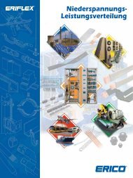
The Need for <strong>Coordinated</strong> <strong>Protection</strong><br />
Reliable protection of structures, industrial and commercial operations<br />
and personnel, demands a systematic and comprehensive approach<br />
to minimizing the threats caused by transient over-voltages.<br />
Grounding, bonding, lightning protection and surge protection all<br />
need to be considered for comprehensive facility electrical protection.<br />
Each of these are interdependent disciplines that need a holistic<br />
design approach to ensure the facility is not left with a vulnerable<br />
“blind spot”. The investment in surge protection can be wasted<br />
if “blind spots” exist. For example, installing a surge protection<br />
device on the power supply to a programmable logic controller is<br />
of little value if the I/O lines are not also protected. In addition, an<br />
air terminal on the facility may capture the lightning energy but<br />
without a dependable ground system, this energy cannot be safely<br />
Ground<br />
Overhead<br />
High Voltage<br />
Transmission<br />
Lines<br />
Lightning protection principles<br />
recommend that all external cabling<br />
enter the building at a common point.<br />
Telephone<br />
Line<br />
Ground<br />
CENTRAL PROCESS<br />
MONITORING<br />
FACILITY<br />
Ground<br />
Potential<br />
Equalization<br />
Clamp<br />
AC Transformer<br />
Sub Station<br />
Distribution<br />
Board<br />
Remote<br />
Sensor<br />
Line Surge<br />
Protectors<br />
(LSPs)<br />
Control Program<br />
Logic<br />
Controller<br />
Universal<br />
Transient<br />
Barriers<br />
DINLINE<br />
Surge Filter<br />
UTB<br />
Universal<br />
Ground<br />
Transient<br />
Barriers<br />
DINLINE<br />
Surge Surge Filter<br />
Reduction<br />
Filter<br />
Ground<br />
www.erico.com 5<br />
dissipated. Equally, even the most expensive Surge <strong>Protection</strong> Devices<br />
(SPDs) are poor performers if a low impedance equipotential ground<br />
is not provided. These interdependent disciplines are best applied<br />
when looking at a total facility rather than at an individual piece of<br />
equipment or portion of the facility.<br />
It is for these reasons that ERICO developed the Six Point Plan of<br />
<strong>Protection</strong>. The plan prompts the consideration of a coordinated<br />
approach to lightning protection, surge and transient protection<br />
and grounding, an approach that embraces all aspects of potential<br />
damage, from the more obvious direct strike to the more subtle<br />
mechanisms of differential earth potential rises and voltage induction<br />
at service entry points.<br />
PROGRAM<br />
LOGIC<br />
CONTROLLER<br />
Load Cell<br />
Protector<br />
MANUFACTURING FACILITY<br />
Ground<br />
Ground<br />
WEIGH BRIDGE<br />
The Six Point Plan applied to a manufacturing facility. Surge and transient protection principles applied to a total facility rather than individual pieces of equipment.<br />
Load Cell<br />
Protector<br />
Where building facilities are<br />
separated by less than 30 metres,<br />
building grounding systems should<br />
be bonded together.<br />
Ground
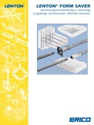
Selecting Surge <strong>Protection</strong><br />
ANSI/IEEE C62.41<br />
IEC 61643 Test Class<br />
VDE Classification<br />
EXPOSURE<br />
PRODUCT SERIES<br />
RECOMMENDED SURGE RATINGS (8/20μ s)<br />
POINT-OF-ENTRY<br />
HIGHLY EXPOSED OR<br />
CRITICALLY IMPORTANT<br />
SITES<br />
CAT C<br />
CAT B<br />
CAT A<br />
I I, II II III<br />
A B C D<br />
POINT-OF-ENTRY<br />
EXPOSED OR RURAL<br />
SITES<br />
RECOMMENDED PRODUCTS<br />
SES200<br />
SES40 120/240<br />
TDS MOVTEC & MPM<br />
TDX200 / TDX300 / TDX400<br />
DSD1150<br />
TSG - SRF<br />
TSG / SGD<br />
TDS / DSD1100<br />
DSD160 & DSD380<br />
6<br />
POINT-OF-ENTRY<br />
INNER CITY SITES<br />
TDX100<br />
TDX50<br />
SUB CIRCUITS OR<br />
NEAR TO<br />
POINT-OF-ENTRY<br />
TDS / DSD140 & TDS / DSD340<br />
TDS130<br />
DSD110<br />
TDF<br />
DISTRIBUTED CIRCUITS,<br />
POWER OUTLETS,<br />
CIRCUITS REMOTE<br />
FROM POINT-OF-ENTRY<br />
HIGH Ng >2 100kA 70kA 40kA 20kA 10kA<br />
MED. Ng 0.5-2 65kA 40kA 20kA 20kA 5kA<br />
LOW Ng
Selecting Surge <strong>Protection</strong><br />
Recommended Surge Ratings –<br />
A Comparison between IEC and IEEE ®<br />
Recommendations<br />
Competition between SPD manufacturers has seen everincreasing<br />
surge ratings being offered to the market, to the<br />
point where surges of this magnitude are unlikely to ever occur<br />
in nature. A number of sources provide information on the<br />
statistical distribution of the current discharge of the direct<br />
lightning strike. Many studies have shown that peak lightning<br />
discharges above 100kA are likely to occur less than 5% of<br />
the time. Combined with the fact that most discharges do not<br />
strike the power line directly but are magnetically or capacitively<br />
coupled to it, and that even under a direct lightning discharge<br />
the energy will split in either direction and be attenuated by<br />
the distribution arresters and line losses, it is not diffi cult to<br />
determine that a smaller fraction of the initial lightning energy<br />
typically enters the facility in question.<br />
ANSI ® /IEEE standard C62.41 has classifi ed the “point-of-entry”<br />
environment as CAT. B/C. Under this classifi cation the highest<br />
expected energy level is 10kA 8/20μs. In contrast, the IEC61312<br />
and DIN VDE 0675 defi nes some differing guidelines. IEC<br />
61000-5-6 and IEC 61312-1 describe protection zone concepts.<br />
This is similar in nature to the ANSI/IEEE C62.41 concept of<br />
Category A, B & C locations.<br />
A “Zone” is where the lightning electromagnetic environment<br />
can be defi ned/controlled. The zones are characterized by<br />
signifi cant changes of electromagnetic conditions at these<br />
boundaries. These will typically be building boundaries, or the<br />
point where protection is installed.<br />
LPZ OA Zone subject to direct strikes<br />
LPZ OB Zone not subjected to direct strikes, but unattenuated<br />
electromagnetic fi elds may occur.<br />
LPZ 1 Zone not subjected to direct strikes and where<br />
currents in this zone are reduced compared to<br />
Zone OB<br />
LPZ 2... If further reductions in current from LPZ 1 are<br />
achieved/required further zones can be created.<br />
Actual surge ratings required in each of these zones is not<br />
exactly defi ned and is largely determined by some sitespecifi<br />
c details. However, to assist with this the VDE0675<br />
Part 6 standard defi nes the minimum class of product that<br />
can be applied to each of these Zones as shown below:<br />
Class A : Arrester for use in low-voltage overhead lines<br />
Class B : Arrester for lightning current equipotential<br />
bonding (must withstand 100kA 8/20μs or<br />
10As charge, twice). Zones OB to 1 (Main<br />
distribution Boards, Sub-Boards)<br />
Class C : Arrester for over-voltage protection (must have<br />
a nominal surge rating of at least 5kA 8/20μs)<br />
Zones 1 to 2 (mainly sub-boards or low exposure<br />
main boards)<br />
Class D : Arrester for portable use on socket-outlets<br />
(must have a nominal surge rating of at least<br />
1.5kA 8/20μs)<br />
www.erico.com 7<br />
LPZ 0A<br />
<strong>Protection</strong> zones defi ned by specifi c product application.<br />
As it can be shown, protection equipment<br />
for power supply systems are classifi ed<br />
as follows, according to its task<br />
Lightning current equipotential bonding arresters must be<br />
capable of conducting a portion of the lightning current without<br />
being destroyed. Over-voltage arresters are only used for limiting<br />
over-voltages at relatively smaller surge currents. The different<br />
“protection zones” assume the division of the initial lightning<br />
current, from zone 0 to higher zones. For zone 0, it is required for<br />
the user to select the lightning protection class, from I - IV : (i.e.<br />
these refer to maximum energy within a direct lightning strike).<br />
<strong>Protection</strong> Level<br />
Level I<br />
Level II<br />
Level III - IV<br />
LPZ 0B<br />
Lightning terminal<br />
collection volume<br />
Shielded<br />
Room<br />
LPZ 2<br />
Current Magnitude<br />
200kA (10/350μs)<br />
150kA (10/350μs)<br />
100kA (10/350μs)<br />
LPZ 1<br />
LPZ 0A<br />
• Lightning Current Arrester<br />
• Over-voltage Arrester<br />
% Exceeded<br />
~ 0.2%<br />
~ 1.5%<br />
~ 3%<br />
The above levels can be selected based on the statistical level of<br />
protection required. A lightning current of 200kA (10/350μs) can be<br />
expected for the <strong>Protection</strong> Level I. This lightning current is divided<br />
as follows in the most exposed sites:<br />
50% (100kA, 10/350μs) discharges via the ground system.<br />
50% (100kA, 10/350μs) fl ows into the supply systems connected to it,<br />
via the three phase equipotential bonding lightning arresters.<br />
On the other hand IEEE has adopted a Scenario II event, in which the<br />
building lightning protection system is subjected to a direct strike<br />
and the energy level sustained by the equipotential bonding surge<br />
arrester(s) is taken to be 10kA (10/350μs) or approximately 100kA<br />
8/20μs as a worst case.<br />
If we adopt IEC or DIN VDE Standard and assume a level of III-IV<br />
lightning protection system, each equipotential bonding surge<br />
arrester connected to a three phase, four wire, power system is<br />
assumed to experience a 12.5 kA (10/350μs) energy level at the<br />
Zone 0 interface due to lightning current sharing.
A Guide to Common Power Distribution Systems<br />
Throughout the world a number of different power distribution systems are used.<br />
This guide identifi es the more common of these systems. The individual product<br />
specifi cation tables detail system suitability.<br />
Description Source<br />
Confi guration<br />
Single Phase<br />
1Ph, 2W+G<br />
Single Phase<br />
1Ph, 3W+G<br />
Also known as<br />
Split phase or<br />
Edison system<br />
Three Phase WYE<br />
without neutral<br />
3Ph Y, 3W+G<br />
Three Phase WYE<br />
with neutral<br />
3Ph Y, 4W+G<br />
Delta<br />
High leg<br />
3Ph Δ, 4W+G<br />
Delta Ungrounded<br />
3Ph Δ, 3W+G<br />
Delta<br />
Grounded corner<br />
3Ph Δ, 3W+G<br />
8<br />
Typical Supply<br />
Voltages<br />
110V<br />
120V<br />
220V<br />
240V<br />
120/240V<br />
480V<br />
120/208V<br />
220/380V<br />
230/400V<br />
240/415V<br />
277/480V<br />
347/600V<br />
120/240V<br />
240V<br />
480V<br />
240V<br />
480V<br />
(L-N)<br />
(L-N/L-L)<br />
(L-L)<br />
(L-N/L-L)<br />
(L-N/L-L)<br />
(L-L)<br />
(L-L)<br />
www.erico.com
A Guide to Common Power Distribution Systems<br />
The IEC ® 60364 series of standards characterizes low-voltage<br />
distribution systems by their grounding method and the arrangement<br />
of the neutral and protective earth conductors. The selection of SPDs<br />
must consider among other issues, the level of over-voltage that may<br />
temporarily occur within the distribution system due to ground faults.<br />
IEC 61643-12 details the temporary over-voltages that may occur<br />
during fault conditions for these systems. To conform with European<br />
wiring rules an SPD with a Uc rating equal to, or greater than, this<br />
TN-C System<br />
In this, the neutral and protective earth conductor combine in a single conductor throughout the system. All exposed-conductive-parts<br />
are connected to the PEN conductor.<br />
www.erico.com 9<br />
value should be selected. Effective protection does not require SPD’s<br />
to be installed in all the modes detailed. The following diagrams<br />
provide guidance on the selection and installation of SPDs on the<br />
more common distribution systems. While three phase WYE systems<br />
are shown, similar logic can be applied to single phase, delta and<br />
other configuration sources.<br />
Uo = Line to neutral voltage of the system<br />
Un = Nominal country specific system voltage (typically Uo x 1.10)<br />
Source Main Distribution Board Sub/Branch Distribution Board<br />
* Install fuse A if supply fuse B exceeds<br />
back-up overcurrent protection rating<br />
* Install fuse C if supply fuse D exceeds<br />
back-up overcurrent protection rating<br />
TN-S System<br />
In this, a separate neutral and protective earth conductor are run throughout. The protective PE conductor can be the metallic sheath of<br />
the power distribution cable or a separate conductor. All exposed-conductive-parts of the installation are connected to this PE conductor.<br />
Source Main Distribution Board Sub/Branch Distribution Board<br />
* Install fuse A if supply fuse B exceeds<br />
back-up overcurrent protection rating<br />
SPDs shown connected L-N and N-PE.<br />
May also be connected L-PE and N-PE.<br />
* Install fuse C if supply fuse D exceeds<br />
back-up overcurrent protection rating
A Guide to Common Power Distribution Systems<br />
TN-C-S System<br />
In this, a separate neutral and protective earth combine in a single PEN conductor. This system is also known as a Multiple Earthed<br />
Neutral (MEN) system and the protective conductor is referred to as the Combined Neutral Earth (CNE) conductor. The supply PEN<br />
conductor is earthed at a number of points throughout the network and generally as close to the consumer’s point-of-entry as possible.<br />
All exposed-conductive-parts are connected to the CNE conductor.<br />
Source Main Distribution Board Sub/Branch Distribution Board<br />
* Install fuse A if supply fuse B exceeds<br />
back-up overcurrent protection rating<br />
SPDs shown connected L-PE and N-PE.<br />
May also be connected L-N and N-PE.<br />
TT System<br />
A system having one point of the source of energy earthed and the exposed-conductive-parts of the installation connected to<br />
independent earthed electrodes.<br />
10<br />
* Install fuse C if supply fuse D exceeds<br />
back-up overcurrent protection rating<br />
Source Main Distribution Board Sub/Branch Distribution Board<br />
* Install fuse A if supply fuse B exceeds<br />
back-up overcurrent protection rating<br />
* Install fuse C if supply fuse D exceeds<br />
back-up overcurrent protection rating<br />
www.erico.com
A Guide to Common Power Distribution Systems<br />
Conventional<br />
MOV<br />
With thermal<br />
disconnect<br />
Distribution Network Confi guration<br />
Between<br />
Phase (line) and<br />
Neutral Conductor<br />
Each Phase (line)<br />
Conductor and PE<br />
Neutral Conductor<br />
and PE<br />
Each Phase (line)<br />
Conductor and PEN<br />
www.erico.com 11<br />
X<br />
X<br />
X<br />
1.45 Uo<br />
SPD Uc Selection:<br />
Uo = Voltage between phase (line) and neutral conductor<br />
X = Not applied<br />
TN-C TN-S<br />
TN-C-S<br />
1.45 Uo<br />
1.45 Uo<br />
Uo<br />
X<br />
TT IT IT<br />
1.45 Uo<br />
√3 Uo<br />
Uo<br />
X<br />
with<br />
neutral<br />
conductor<br />
1.45 Uo<br />
√3 Uo<br />
Uo<br />
X<br />
without<br />
neutral<br />
conductor<br />
X<br />
√3 Uo<br />
SPD selection must consider the level of over-voltage that may occur within the distribution system<br />
due to ground faults. The above IEC ® table shows over-voltages that may occur during fault conditions<br />
for the various systems. An SPD with a Uc equal or greater than this value should be selected.<br />
With overcurrent<br />
fusing<br />
With Transient<br />
Disciminating<br />
Technology<br />
IT System<br />
A system having no direct connection between live parts and earth but all exposed-conductive-parts of the installation being connected to independent<br />
earthed electrodes.<br />
Metal Oxide Varistors (MOVs) Gas Discharge Tubes (GDTs)<br />
Two terminal<br />
gas arrester<br />
Three terminal<br />
gas arrester<br />
With failsafe<br />
device<br />
Spark Gap<br />
Uo<br />
X<br />
Other Symbols<br />
Triggered<br />
Spark Gap<br />
Silicon<br />
<strong>Protection</strong><br />
Audible<br />
Alarm
Data and Signal Line <strong>Protection</strong><br />
How to select surge protection for<br />
data, signalling and control circuits<br />
Knowing where to install surge protection can be difficult. To<br />
ensure cost-effective protection is provided for data, signalling<br />
and control circuits, two issues need to be considered:<br />
• Where should the SPDs be installed?<br />
• What type of SPD is appropriate for each circuit type<br />
and location?<br />
Where should the SPD(s) be installed?<br />
Communications devices are at risk from transients being<br />
induced onto the interconnecting signal lines. The use of<br />
surge protection barriers, installed at either end of the lines,<br />
provides cost effective protection. Communication or signal<br />
lines that enter or exit the building pose the highest risk. In<br />
such circumstances, protection devices should be installed<br />
at the point-of-entry or at the equipment termination itself.<br />
Internal wiring which extends more than 10 to 15m should<br />
also be protected. Twisting or shielding of cables provides a<br />
level of protection, however this should not be regarded as<br />
sufficient for the sensitive interfaces that characterize today’s<br />
communication devices.<br />
Power Distribution<br />
Board<br />
Mains Power Feed<br />
Primary Power<br />
<strong>Protection</strong> (SRF)<br />
Secondary<br />
Power <strong>Protection</strong><br />
Modem<br />
MODEM<br />
Transient Barrier<br />
CENTRAL LOCATION<br />
PROGRAM<br />
LOGIC<br />
CONTROLLER<br />
Transient Barrier<br />
PROCESS CONTROL<br />
Transient Barrier<br />
Transient Barrier<br />
Low Voltage (DC or AC)<br />
Secondary Power Supply<br />
to Local Location<br />
Low Voltage (DC or AC)<br />
Secondary Power Supply<br />
to remote location<br />
Control / Data Signal<br />
to remote location<br />
Control / Data<br />
Signal to<br />
Local Location<br />
Transient Barrier<br />
Line Surge Protector<br />
Local<br />
Sensor<br />
12<br />
How to select an SPD for a<br />
given location<br />
Five parameters must be considered to ensure that surge<br />
protection devices for use on data, signalling or control circuits<br />
are effective and do not adversely affect operation of the<br />
circuit.<br />
1) SPDs are designed to clamp the excess transient voltage to<br />
safe levels sustainable by the equipment, yet should not<br />
interfere with the normal signalling voltages. As a guide, the<br />
SPD clamping voltage should be selected to be approximately<br />
20% higher than peak working voltage of the circuit.<br />
2) The line current rating of the SPD should be sufficient to<br />
handle the maximum expected signalling current.<br />
3) The SPD bandwidth should be sufficient to allow correct<br />
operation of the system without adverse attenuation. This<br />
ensures that the attenuation of the SPD at the nominal<br />
operating frequency of the system does not exceed the<br />
stated limit. For most SPDs, frequency attenuation data or<br />
a maximum recommended baud rate is generally specified.<br />
4) The connection termination, mounting method, number<br />
of lines to be protected and other physical aspects must be<br />
considered.<br />
5) The SPD surge rating should be appropriate for the intended<br />
location. For circuits internal to the building, surge ratings<br />
of 1-5kA are generally sufficient. For the protection of<br />
circuits that connect to exposed lines entering or exiting the<br />
facility, 10-20kA is recommended. Alternatively a protocol or<br />
standard may be specified that defines the above parameters.<br />
All UTB products are rated 20kA for higher exposure areas.<br />
LOAD CELL<br />
INSTRUMENT<br />
LSP LSP<br />
Line<br />
Surge<br />
Protector<br />
Transient Barrier<br />
Transient Barrier<br />
LCP<br />
Load Cell<br />
Protectors<br />
LCP<br />
Other Sensors<br />
Sensor<br />
Sensor<br />
Weighbridge<br />
• Grounding connections are not shown<br />
www.erico.com
Data and Signal Line <strong>Protection</strong><br />
Sample Applications<br />
2-Wire Isolated Ground Transducers/Sensors<br />
2-Wire Sensors<br />
Protecting Sensors in Hazardous Locations<br />
Sensor<br />
Field<br />
Sensor<br />
Signal Ground<br />
Pressure<br />
Transmitter<br />
Driver<br />
+<br />
-<br />
Powered Sensor <strong>Protection</strong><br />
Flow<br />
Meter<br />
+ -<br />
Signal<br />
UTB-XSPG UTB-XSPG<br />
UTB-XSP UTB-XSP<br />
UTB-EX<br />
www.erico.com 13<br />
1 ’<br />
2 ’<br />
3 ’<br />
1 ’<br />
2 ’<br />
1 ’<br />
2 ’<br />
1<br />
2<br />
3<br />
UTB30DPS<br />
1 ’<br />
2 ’<br />
3 ’<br />
4 ’<br />
1<br />
2<br />
3<br />
4<br />
Protective Ground<br />
1<br />
2<br />
1<br />
2<br />
4 - 20mA<br />
Multiple Sensor or up to 4-Wire Sensor<br />
Fire<br />
Alarm<br />
Fire<br />
Alarm<br />
+ -<br />
NC<br />
C<br />
+ -<br />
NC<br />
C<br />
UTB-XDP<br />
UTB30DPS<br />
1 ’<br />
2 ’<br />
3 ’<br />
4 ’<br />
1<br />
2<br />
3<br />
4<br />
Hazardous Safe<br />
1<br />
2<br />
3<br />
1<br />
2<br />
UTB30DPS<br />
1<br />
2<br />
3<br />
4<br />
1<br />
2<br />
3<br />
4<br />
UTB-EX<br />
1<br />
2<br />
1 ’<br />
2 ’<br />
3 ’<br />
4 ’<br />
1 ’<br />
2 ’<br />
3 ’<br />
4 ’<br />
1 ’<br />
2 ’<br />
1 ’<br />
2 ’<br />
3 ’<br />
1 ’<br />
2 ’<br />
UTB30DPS<br />
Signal Ground<br />
+<br />
-<br />
+<br />
-<br />
Protective Ground<br />
24 VDC<br />
+ -<br />
Power Supply<br />
4-20mA<br />
1 1<br />
2<br />
’<br />
2 ’<br />
1<br />
Sensor 1 Output 1<br />
2<br />
Sensor 2<br />
3 ’<br />
4 ’<br />
3<br />
4<br />
UTB-XDP<br />
3<br />
4<br />
1 ’<br />
2 ’<br />
3 ’<br />
4 ’<br />
Output 2<br />
24 VDC<br />
Alarm<br />
Central Location<br />
Current<br />
Loop<br />
Supply<br />
Output<br />
250 Ω
Data and Signal Line <strong>Protection</strong><br />
Guide to Data and Signaling Circuits<br />
The selection of an SPD for communication and signalling<br />
circuits requires knowledge of the:<br />
1) Maximum Continuous Operating Voltage (Uc)<br />
2) Maximum line current (IL)<br />
3) Frequency<br />
4) Termination (connector type and/or impedence)<br />
14<br />
Where a protocol is known, this often eliminates the need<br />
to verify product selection criteria 1-3, and occasionally 4.<br />
A number of different SPDs often meet the requirements as<br />
defined by the protocol, so the final choice of which SPD to use<br />
is often determined by its type of physical connection, number<br />
of lines to be protected, or its surge rating. Some protocols do<br />
not define the actual connector or pin configuration, and in<br />
some cases, not all lines defined by the protocol will be used.<br />
Please refer to the documentation provided with the equipment<br />
requiring protection to ensure the proposed protection modes<br />
are adequate and that the SPD’s characteristics will not interfere<br />
with normal system operation.<br />
Protocol/Standard Description Applicable SPD Series<br />
RS-232 (V.24) Unbalanced, bi-directional communication circuit. UTB 15 SP (1) , UTB 15DP (2)<br />
Although standard allows +/- 25 V signaling, use of more than<br />
+/- 12 V is uncommon<br />
UTB 5 (1)<br />
RS-422 (V.11) Industrial version of RS-232. 0-5 V balanced signaling UTB 5 (1)<br />
RS-423 Similar to RS-232 but +/- 5 V signaling used UTB 5 (1)<br />
RS-485 Similar to RS-422 but allows multiple devices to communicate.<br />
DB-9 connector is common<br />
UTB 5 (1)<br />
Ethernet Ethernet is the term used to describe a family of communication<br />
protocols.<br />
LAN RJ45 Series<br />
Cat 4 * 10BaseT is a 10 MHz system using twisted pair of coax cables<br />
Cat 5 * 100BaseT is a 100 MHz system using twisted pair cables<br />
10BaseT Cat 4 is a cable specifi cation that allows operation up to 10BaseT,<br />
100BaseT<br />
while Cat 5 allows operation up to 100BaseT frequencies.<br />
Telephone Lines UTB SA (2) , UTB TA (2)<br />
4-20 mA current loop<br />
Common industrial communications protocol used to interface with UTB xDP, UTB 30DPS, UTB xSP<br />
(with HART)<br />
transducers etc<br />
Binary Signals UTB xSP (1) , UTB xDP (1)<br />
Bitbus (IEEE 1118) Digital communications network based on RS-485 and SDLC allowing<br />
communication between PLCs and controllers<br />
UTB 5 (1)<br />
CAN-Bus (data signal line) Differential serial communications protocol defi ned in ISO 11898<br />
standard<br />
DeviceNet (data signal line) Communication protocol used to connect industrial devices such<br />
as limit switches, motor starters to PLCs and controllers<br />
M-Bus Communication protocol for networking and remote reading of heat,<br />
gas, water, and energy meters<br />
UTB 60 (1)<br />
Ex (I) - HART, 4-20 mA circuit,<br />
measurement circuits<br />
Hazardous locations UTB15 Ex , UTB30 Ex<br />
Profi bus - PA Process fi eld bus - process automation. Ideal for explosion<br />
- hazardous areas<br />
UTB30 Ex<br />
Strain gauge / Load cells As used in weigh bridges etc. LCP01A<br />
ASDL Asymmetric Digital Subscriber Line. Protocol for data communication<br />
over copper telephone lines. Uses single copper wire pair.<br />
UTB TA (2) , UTB SA (2)<br />
HDSL High bit rate Digital Subscriber Line. Protocol for data communication<br />
over copper telephone lines. Uses two copper wire pairs.<br />
ISDN Integrated Service Digital Network. Protocol for voice and data over<br />
copper telephone lines<br />
(1) The number of UTB’s required is dependent on the number of wires being used in the signalling circuit. UTBs are designed for<br />
balanced circuits and each UTB will protect one pair of wires. The UTB can also be used to protect two unbalanced circuits.<br />
(2) The UBT TA is rated to 500 A 8/20 us and intended to meet US NEC requirements. The UTB SA are rated to 20 kA 8/20 μs and<br />
specifi cally designed and approved for use on the Australian telecommunication network.<br />
www.erico.com
Surge <strong>Protection</strong> And Surge Ratings<br />
The stress, which an SPD will experience under surge<br />
conditions, is a function of many complex and interrelated<br />
parameters. These include:<br />
- Location of the SPD(s) within the structure – are they<br />
located at the main distribution board or within the<br />
facility at secondary board, or even in front of the<br />
end-user equipment?<br />
- Method of coupling the lightning strike to the facility –<br />
for example, is this via a direct strike to the structure’s<br />
LPS, or via induction onto building wiring due to a<br />
nearby strike?<br />
- Distribution of lightning currents within the structure –<br />
for example, what portion of the lightning current enters<br />
the earthing system and what remaining portion seeks<br />
a path to remote grounds via the power distribution<br />
system and equipotential bonding SPDs?<br />
- Type of power distribution system – the distribution<br />
of lightning current on a power distribution system is<br />
strongly influenced by the grounding practice for the<br />
neutral conductor. For example, in the TN-C system with<br />
its multiple earthed neutral, a more direct and lower<br />
impedance path to ground is provided for lightning<br />
currents than in a TT system.<br />
- Additional conductive services connected to the facility<br />
– these will carry a portion of the direct lightning<br />
current and therefore reduce the portion which flows<br />
through the power distribution system via the lightning<br />
equipotential bonding SPD.<br />
- Type of waveshape – it is not possible to simply consider<br />
the peak current which the SPD will have to conduct,<br />
one also has to consider the waveshape of this surge. It<br />
is also not possible to simply equate the areas under the<br />
current-time curves (also referred to as the action integral)<br />
for SPDs under different waveshapes.<br />
Many attempts have been made to quantify the electrical<br />
environment and “threat level” which an SPD will<br />
experience at different locations within a facility. The<br />
IEC standard on lightning protection, IEC 62305-4<br />
“<strong>Protection</strong> against lightning - Part 4: Electrical and<br />
electronic systems within structures” has sought to address<br />
this issue by considering the highest surge magnitude<br />
which may be presented to an SPD based on the lightning<br />
protection level (LPL) being considered. For example, this<br />
standard postulates that under a LPL I the magnitude of a<br />
direct strike to the structure’s LPS may be as high as 200 kA<br />
10/350. While this level is possible, its statistical probability<br />
of occurrence is approximately 1%. In other words, 99%<br />
of discharges will be less than this postulated 200 kA peak<br />
current level.<br />
An assumption is made that 50% of this current is<br />
conducted via the building’s earthing system, and 50%<br />
returns via the equipotential bonding SPDs connected to<br />
www.erico.com 15<br />
a three wire plus neutral power distribution system. It is also<br />
assumed that no additional conductive service exists. This implies<br />
that the portion of the initial 200 kA discharge experienced by<br />
each SPD is 25 kA.<br />
Simplified assumptions of current dispersion are useful in<br />
considering the possible threat level, which the SPD(s) may<br />
experience, but it is important to keep in context the assumptions<br />
being made. In the example above, a lightning discharge of<br />
200 kA has been considered. It follows that the threat level to<br />
the equipotential bonding SPDs will be less than 25 kA for 99%<br />
of the time. In addition, it has been assumed that the waveshape<br />
of this current component through the SPD(s) will be of the<br />
same waveshape as the initial discharge, namely 10/350, while<br />
in reality the waveshape have been altered by the impedance<br />
of building wiring, etc.<br />
Many standards have sought to base their considerations on field<br />
experience collected overtime. For example, the IEEE ® guide<br />
to the environment C62.41.1 and the recommended practice<br />
C62.41.2 present two scenarios of lightning discharge and<br />
different exposure levels under each of these depending on the<br />
location where the SPD is installed. In this standard, Scenario II<br />
depicts a direct strike to the structure, while Scenario I depicts<br />
a nearby strike and the subsequent conducted current into a<br />
structure via power and data lines. The highest surge exposure<br />
considered feasible to an SPD installed at the service entrance to a<br />
facility under Scenario I is 10 kA 8/20, while under Scenario II it is<br />
considered to be 10 kA 10/350 (exposure Level 3).<br />
From the above, it is apparent that the selection of the<br />
appropriate surge rating for an SPD depends on many complex<br />
and interconnected parameters. When addressing such<br />
complexities, one needs to keep in mind that one of the more<br />
important parameters in selecting an SPD is its limiting voltage<br />
performance during the expected surge event, and not the<br />
energy withstand which it can handle.<br />
LPZ 0A<br />
LPZ 0B<br />
Lightning terminal<br />
collection volume<br />
Shielded<br />
Room<br />
LPZ 2<br />
LPZ 1<br />
<strong>Protection</strong> zones defined by specific product application.<br />
LPZ 0A
Advanced Technologies – The ERICO Advantage<br />
Transient Discriminating Technology<br />
To meet the fundamental requirements of performance, longer<br />
service life and greater safety under real world conditions, ERICO<br />
has developed Transient Discriminating (TD) Technology.<br />
This quantum leap in technology adds a level of “intelligence”<br />
to the Surge <strong>Protection</strong> Device enabling it to discriminate<br />
between sustained abnormal over-voltage conditions and true<br />
transient or surge events. Not only does this help provide more<br />
reliable operation under practical application, but it also prolongs<br />
the life of the protector since permanent disconnects are not<br />
required as a means of achieving internal over-voltage protection.<br />
Traditional Technologies<br />
Conventional SPD technologies utilize metal oxide varistors and/<br />
or silicon avalanche diodes to clamp or limit transient events.<br />
However, these devices are susceptible to sustained 50/60Hz<br />
mains over-voltage conditions which often occur during faults<br />
to the utility system. Such occurrences present a significant<br />
safety hazard when the suppression device attempts to clamp<br />
the peak of each half cycle on the mains over-voltage. This<br />
condition can cause the device to rapidly accumulate heat and<br />
in turn fail with the possibility of inducing a fire hazard.<br />
The Core of TD Technology<br />
The secret to transient discriminating technology is its active<br />
frequency discrimination circuit. This patented device can<br />
Traditional Technology Active TD Technology<br />
TD TECHNOLOGY PROVIDES<br />
CONTINUED PROTECTION -<br />
EVEN AFTER OVER-VOLTAGES<br />
Typical Supply Problems<br />
1. Transient<br />
Impluse<br />
2. Substantial<br />
Over-voltage<br />
1. Transient<br />
Impluse<br />
16<br />
discriminate between a temporary over-voltage (TOV) condition<br />
and a very fast transient, which is associated with lightning or<br />
switching-induced surges. When the transient frequencies are<br />
detected, the patented Quick-Switch within TD activates to allow<br />
the robust protection to limit the incoming transient. The frequency<br />
discriminating circuit that controls the Quick-Switch helps ensure<br />
that the SPD device is immune to the effects of a sustained 50 or<br />
60Hz TOV. This allows the device to keep operating, in order to<br />
help provide safe and reliable transient protection, even after an<br />
abnormal over-voltage condition has occurred.<br />
Meeting & Exceeding UL ® Standards<br />
The range of surge protection devices from ERICO employing<br />
TD technology has been specifically designed to meet and<br />
exceed the new safety requirements of UL 1449 Edition 3. To<br />
meet the abnormal over-voltage testing of UL 1449 Edition 3,<br />
many manufacturers of SPD devices have incorporated fuse<br />
or thermal disconnect devices which permanently disconnect<br />
all protection from the circuit during an over-voltage event.<br />
Transient discriminating technology on the other hand will<br />
allow the SPD device to experience an abnormal overvoltage<br />
up to twice its nominal operating voltage and still<br />
remain operational even after this event! This allows the<br />
device to help provide reliable and continuous protection to<br />
your sensitive electronic equipment. TD technology is<br />
especially recommended for any site where sustained<br />
over-voltages are known to occur, and where failure of<br />
traditional SPD technologies cannot be tolerated.<br />
The UL 1449 testing standard addresses the safety of an SPD<br />
device under temporary and abnormal overvoltage conditions, but<br />
does not specifically mandate a design that will give a reliable,<br />
long length of service in the real world. Specifically, UL 1449<br />
tests that the SPD remains operational at 10% above nominal<br />
supply voltage, allowing SPD manufacturers to design products<br />
that permanently disconnect just above that. Most reputable<br />
manufacturer’s designs allow for up to a 25% overvoltage,<br />
while TD technology from ERICO gives even greater overhead.<br />
Traditional Technology Response<br />
1. Transient<br />
overshoots &<br />
is clamped to<br />
approx. 600 V<br />
Clamping threshold<br />
TD Technology Solution<br />
1. Discriminating circuit<br />
detects transient<br />
and Quick Switch<br />
operating clamping<br />
transient<br />
2. Over-voltage<br />
threshold exceeded,<br />
protection attempts<br />
to clamp, overheats<br />
due to long<br />
exposure and fails<br />
2. <strong>Protection</strong> does<br />
not attempt to<br />
clamp supply<br />
voltage<br />
3. <strong>Protection</strong><br />
has failed.<br />
Equipment<br />
exposed to<br />
subsequent<br />
transient &<br />
is damaged<br />
3. <strong>Protection</strong> still<br />
working and<br />
clamps transient<br />
www.erico.com
Glossary of Terminology<br />
8/20μs Current Waveshape<br />
A current impulse with a virtual front time of 8μs and a time<br />
to half-value of 20μs.<br />
Aggregate Surge Rating<br />
The sum of the surge ratings of individual voltage limiting<br />
components, connected in parallel, in the device.<br />
Note: This fi gure does not indicate the maximum discharge current (Imax) of<br />
the device. It does however provide an indication of the expected SPD life.<br />
Users should be aware that certain manufacturers may incorrectly claim the<br />
aggregate surge rating of MOV material used in their device as its Imax.<br />
Non-perfect current sharing between parallel MOVs, and the inability of<br />
series over-current or thermal disconnects to carry the full surge current,<br />
generally means that the maximum discharge current which the SPD can<br />
withstand is less than its aggregate surge rating.<br />
Attenuation<br />
The ability of an SPD to reduce electrical noise interference,<br />
measured in decibels. Attenuation varies with frequency,<br />
so it is usual to specify the attenuation of the SPD at a<br />
particular frequency; commonly 100kHz.<br />
Backup Overcurrent <strong>Protection</strong><br />
An external overcurrent protective device installed prior to<br />
the SPD. Such a device may be required if the overcurrent<br />
limiting device on the service is larger than that required by<br />
the SPD or connecting wiring.<br />
Class I test<br />
SPD tested with maximum impulse current (Iimp) and nominal<br />
discharge current (In).<br />
Class II test<br />
SPD tested with maximum discharge current (Imax) and<br />
nominal discharge current (In).<br />
Class III test<br />
SPD tested with combination wave.<br />
Distribution System<br />
Defi nes the electrical power distribution system. The<br />
distribution system is usually described by confi guration of<br />
the phases, neutral and ground conductor confi guration on<br />
the secondary side of the supply transformer. Refer to pages<br />
10-12 for further information.<br />
Follow Current (If)<br />
The current supplied by the electrical power distribution<br />
system which fl ows through the SPD after a discharge<br />
current impulse. The follow current is signifi cantly higher<br />
than the operating current, and is normally high for voltage<br />
switching type SPDs (e.g. spark gaps) since the arc voltage<br />
falls below the AC supply voltage after fi ring.<br />
Impulse Current (Iimp)<br />
Peak impulse current withstand with a 10/350μs current<br />
waveshape. This is often used for the classifi cation of<br />
SPDs tested to Test Class I, but is not the only acceptable<br />
waveshape.<br />
Insertion Loss<br />
The insertion loss of an SPD is usually only stated for two<br />
port devices for use on low voltage data systems. It is a<br />
measure of the ratio of voltage at the output to the input at<br />
the device under test. The insertion loss is usually stated for<br />
a given frequency and measured in decibels.<br />
www.erico.com 17<br />
Leakage Current<br />
The current fl owing to the ground conductor when the SPD is<br />
connected to the nominal supply voltage Un.<br />
Let-through Voltage<br />
Another term often used to describe the measured limiting<br />
voltage.<br />
Note: This measurement may be carried out with, or without, the presence of<br />
the nominal AC power (Un) being applied to the SPD. As such, the results may be<br />
different and the user should take cognizance of this in making any comparative<br />
assessments.<br />
Location Categories<br />
Various standards attempt to defi ne the electrical environment at<br />
which an SPD may be installed, into location categories or zones.<br />
Note: The user should be aware that international consensus has not<br />
been reached on these classifi cations, nor on the size of expected<br />
surge activity, which may occur. Further, the user should note that the<br />
demarcation of these zones do not form literal boundaries, but are rather<br />
a gradual transition.<br />
Maximum Continuous Operating Voltage (Uc)<br />
The maximum r.m.s. or d.c. voltage which may be continuously<br />
applied to the SPD’s mode of protection without degradation or<br />
inhibiting its correct operation.<br />
Note: Specifi cations given in the catalog generally are phase (L-N) voltages.<br />
Maximum Discharge Current (Imax)<br />
The maximum single shot current, having an 8/20μs waveshape,<br />
which the SPD can safely divert.<br />
Measured Limiting Voltage<br />
The maximum voltage measured across the SPD’s terminals<br />
during the application of an impulse of specifi ed waveshape and<br />
amplitude.<br />
Modes of <strong>Protection</strong><br />
SPDs may provide protection line-to-ground, line-to-neutral,<br />
neutral-to-ground or in combinations thereof. These paths are<br />
referred to as the modes of protection.<br />
Note: The user is advised that not all modes require protection, and more is not<br />
necessarily better when selecting an SPD. As an example, the N-G mode is not<br />
required when the SPD is installed at the primary service entrance of a TN-C-S<br />
electrical distribution system, due to the Neutral-Ground bond at this point. The L-L<br />
mode is generally not provided for systems with neutral conductors since the L-N<br />
modes also protect the L-L modes. Similarly, the L-G mode can be protected via the<br />
L-N and N-G modes.<br />
Nominal Discharge Current (In)<br />
The peak value of the current fl owing through the SPD during<br />
the application an 8/20μs waveshape.<br />
Note: IEC 61643-1requires SPDs tested to Test Class II, to withstand 15 impulses<br />
at In followed by 0.1, 0.25, 0.5, 0.75 and 1.0 times Imax.<br />
Nominal (System) Voltage (Un)<br />
The L-N voltage by which an electrical power system is<br />
designated. Under normal system conditions, the voltage<br />
at the supply terminals may differ from the nominal voltage<br />
as determined by the tolerance of the supply system<br />
(normally +/- 10%).<br />
One-port SPD<br />
An SPD connected in shunt (parallel) with the circuit to be<br />
protected. A one port device may have separate input and<br />
output terminals, but without a specifi c series impedance<br />
between these terminals. This type of connection is also<br />
known as a Kelvin connection.
Glossary of Terminology<br />
Operating Current<br />
The current drawn (per phase) by the SPD when energized<br />
at the nominal operating voltage Un.<br />
Note: For SPDs with integral series fi ltering, the total current drawn may be<br />
greater than the real rms current consumption (i.e. VA may be greater than<br />
Watts). This is due to the presence of the internal fi ltering capacitance.<br />
Over-current <strong>Protection</strong><br />
An over-current device, such as a fuse or circuit-breaker,<br />
which could be part of the electrical distribution system<br />
located externally and up-stream of the SPD. May provide<br />
protection to the SPD, the connecting wiring and provide a<br />
means of externally isolating the SPD.<br />
Protective Earth (PE)<br />
The IEC ® 60364 series characterizes low-voltage distribution<br />
systems by their grounding methods and the confi guration<br />
of the neutral and protective conductors. The Protective<br />
Earth is commonly referred to as “ground”, or “earth”, in<br />
many regions.<br />
Rated Load Current (IL)<br />
Maximum continuous rated current that can be supplied<br />
to a load connected to the protected output of an SPD.<br />
Normally only stated for two port, series connected, SPDs.<br />
Residual Voltage<br />
In IEC terminology this refers to the peak value of the<br />
voltage that appears between the terminals of an SPD due<br />
to the passage of discharge current In. NZS/AS 1768 refers<br />
to this as the let-through voltage, a measurement obtained<br />
when the stated test impulse is superimposed on top of the<br />
nominal system voltage Un.<br />
Secondary Surge Arrester<br />
A loosely used term given to SPDs intended for operation<br />
on medium voltage systems (>1kV). Within the USA,<br />
a secondary surge arrester defi nes an SPD Listed by<br />
Underwriters Laboratories Inc. for use on LV and MV<br />
systems at locations prior to the main overcurrent<br />
disconnect to the facility.<br />
Note: Secondary Surge Arrester Listing is generally considered to have less<br />
demanding safety requirements than those for UL ® 1449 Transient Voltage<br />
Surge Arrester Listing.<br />
Short Circuit Current Rating (SCCR)<br />
The short-circuit current rating of the SPD. Required by USA<br />
National Electric Code (NEC ® ) for TVSS devices.<br />
SPD Disconnector<br />
An IEC term used to describe a device (internal and/or<br />
external) for disconnecting an SPD from the electrical power<br />
system.<br />
Note: This disconnecting device is not required to have isolating capability. It<br />
is to prevent a persistent fault on the system and is used to give an indication<br />
of the SPD failure. There may be more than one disconnector function,<br />
for example an over-current protection function and a thermal protection<br />
function. These functions may be integrated into one unit or performed in<br />
separate units.<br />
Spark-over Voltage<br />
The voltage at which a switching type SPD (generally of<br />
the spark gap type) will initiate conduction. This value is<br />
normally specifi ed for a voltage increasing at 1kV/s.<br />
18<br />
Stand-off Voltage<br />
The maximum voltage, which can be applied to an SPD, without<br />
triggering it into a fully conductive state.<br />
Note: This voltage is normally higher than the maximum continuous operating<br />
voltage (MCOV or Uc) of the SPD. It is not intended that the SPD be operated at<br />
this voltage.<br />
Status Indicator<br />
A device(s) that indicates the operational status of the SPD, or of<br />
a particular mode of its protection.<br />
Note: Such indicators may be local with visual and/or audible alarms and/or may<br />
have remote signaling and/or output contact capability.<br />
Suppressed Voltage Rating (SVR)<br />
A special case of the measured limiting voltage specifi c to the<br />
UL 1449 Listing of an SPD.<br />
Note: This test is performed using a small 500A 8/20μs current limited impulse,<br />
and the clamping voltage recorded at the ends of 6”connecting leads. The result<br />
obtained is rounded up to the nearest value given in a table.<br />
Surge <strong>Protection</strong> Device (SPD)<br />
An IEC term used to describe a device intended to limit transient<br />
over-voltages and divert surge currents. It contains at least one<br />
non-linear component.<br />
Surge (Reduction) Filter<br />
A two-port series fi ltering type of SPD specifi cally designed to<br />
reduce the rate-of-rise of voltage (dv/dt) of the pre-clamped<br />
waveform. Such a device normally contains a fi lter with low-pass<br />
performance.<br />
Transient Voltage Surge Suppressor (TVSS)<br />
An SPD tested to meet the safety requirements of UL 1449<br />
- Standard for Transient Voltage Surge Suppressors. UL 1449<br />
defi nes the basic safety requirements for TVSS devices installed<br />
on electrical circuits up to 600V. The United States National<br />
Electric Code (NEC) only permits TVSS devices to be installed<br />
after (downstream of) the main over-current disconnect to a<br />
facility.<br />
Two-port SPD<br />
An SPD with two sets of terminals, input and output (line and<br />
equipment), and with a specifi c impedance inserted between<br />
these terminals. These are often referred to as series (in-line)<br />
connected SPDs and generally contain wave-shaping fi lters in<br />
addition to simple shunt-only protection.<br />
Voltage <strong>Protection</strong> Level (Up)<br />
Similar to the measured limiting voltage, the voltage protection<br />
level characterizes the performance of an SPD in limiting the<br />
voltage across its terminals.<br />
Note: The voltage protection level is the measured limiting voltage<br />
recorded under a specifi ed current magnitude and waveshape, and<br />
rounded up to the next highest voltage selected from a list of preferred<br />
values found in IEC 61643-1 Standard for surge protective devices<br />
connected to low-voltage power distribution systems. For SPDs tested to<br />
Test Class I, Up is generally stated using a 10/350 Iimp and for SPDs tested<br />
to Test Class II, using an 8/20μs Imax.<br />
Voltage <strong>Protection</strong> Rating (VPR)<br />
A rating selected from a list of preferred values as given in<br />
Table 63.1 of ANSI ® /UL 1449 and assigned to each mode<br />
of protection. The value of the VPR is determined as the<br />
nearest highest value taken from Table 63.1 to the measured<br />
limiting voltage determined during the transient-voltage surge<br />
suppression test using the combination wave generator at a<br />
setting of 6 kV, 3 kA.<br />
www.erico.com
SES40P<br />
Service Entrance Suppression<br />
The SES40 Series of Surge <strong>Protection</strong> Devices provide<br />
economical protection against damaging transients<br />
and surge events. These products are UL and cUL ®<br />
listed to 1449 Edition 3 as Type 1 devices. This<br />
allows them to be installed on the line or load side<br />
of the service panel in accordance with the NEC ®<br />
2011 without the requirement for additional circuit<br />
breakers or fuses. The DC models have an additional<br />
listing under UL 1449 for use on photovoltaic systems.<br />
www.erico.com 19<br />
Electrical Power <strong>Protection</strong><br />
Panelboard Mount<br />
Primary applications are service entrance, branch and<br />
OEM panels, solar cominer boxes, UL 96A lightning<br />
protection installations and light pole applications.<br />
The housing is constructed of UV-stabilized thermoplastic<br />
and designed to meet the UL 50 Type 4 rating,<br />
making it ideal for both indoor and outdoor NEMA<br />
4X applications. Most models have a 20kA nominal<br />
discharge current rating, the highest level recognized<br />
under UL 1449 Edition 3 standard. Listed as a Type 1<br />
SPD to UL 1449 3rd Edition, the SES40 Series can be<br />
installed in a Type 1 or 2 location in accordance with<br />
the NEC 2011.<br />
Model SES40120/240SP SES401201P SES402083P SES402401P SES404803P SES404801P SES40300DC SES40600DC<br />
Nominal System Voltage, Un 120/240 V 120 V 120/208 V 240 V 277/480 V 480 V 300 Vdc 600 Vdc<br />
Distribution System 1Ph 2W+G 1Ph 2W+G 3Ph 4W+G 1Ph 2W+G<br />
3Ph Δ 3W+G<br />
3Ph 4W+G 1Ph 2W+G<br />
3Ph Δ 3W+G<br />
DC 2W G DC 2W+G<br />
Max Cont. Operating Voltage,<br />
Uc<br />
150/300 VAC 150 VAC 150/300 VAC 300 VAC 340/590 VAC 580 VAC 360 VDC 600 VDC<br />
Frequency 0-60 Hz<br />
Max Discharge Current, Imax 40 kA 8/20 μs per mode<br />
Nominal Discharge Current, 20kA 8/20 μs per mode 10 kA 8/20<br />
In<br />
μs per mode<br />
<strong>Protection</strong> Modes L-N, L-L L-G, N-G L-N, L-G, L-G, N-G L-N, L-G, L-G, N-G +ve to G, +ve to G,<br />
N-G, L-L<br />
N-G, L-L<br />
-ve to G -ve to G<br />
Technology MOV with thermal disconnect<br />
Short Circuit Current Rating, 200 kAIC 100 kAIC<br />
Isc<br />
Voltage <strong>Protection</strong> Rating<br />
(VPR)<br />
Features<br />
• Compact NEMA ® -4X enclosure design can be fl ush mounted<br />
or installed in a small space<br />
• LED status indication fl ag for status monitoring<br />
• 40 kA 8/20 μs maximum surge rating provides protection suitable<br />
for service entrance and distribution panels<br />
• CE, UL ® 1449 Edition 3 Listed<br />
• Optional bracket for mounting within panel backplane<br />
800 V @ 3kA 800 V @ 3kA 800 V @ 3kA 1200 V @ 3kA 1200 V @ 3kA 1200 V @ 3kA 1,500V @ 3 kA 2,500V @ 3 kA<br />
Status LED indicator<br />
Dimensions H x D x W: mm 62 x 87 x 99 (2.44 x 3.43 x 3.90)<br />
(in)<br />
Weight: kg (lbs) 0.18 (0.40) 0.32 (0.70) 0.18 (0.40) 0.32 (0.70) 0.18 (0.40)<br />
Enclosure NEMA 4X, UV stabilized thermoplastic<br />
Connection #12 AWG Wiring Leads<br />
Mounting 3/4” straight nipple with conduit nut for mounting through standard 1.14” diameter knockout<br />
Temperature -40°C to 80°C (-40°F to 176°F)<br />
Approvals CE, UL 1449 Edition 3 Listed Type 1/2 CE CE, UL 1449 CE, UL 1449<br />
Ed. 3 for DC Ed. 3 for DC<br />
general use PV use<br />
Surge Rated to Meet UL 1449 Edition 3 In 20 kA mode UL 1449 Ed. 3<br />
in 10 kA mode<br />
Available Options Mounting bracket (SES40BRK)
SES40<br />
Service Entrance Suppression<br />
Features<br />
• Compact NEMA ® -4 enclosure design can be fl ush mounted<br />
or installed in a small space<br />
• LED status indication fl ag for status monitoring<br />
• 120/240 VAC operating voltage suits the most common<br />
power distribution system for residential or small<br />
commercial buildings<br />
• 40 kA 8/20 μs maximum surge rating provides protection<br />
suitable for service entrance and distribution panels<br />
• CE, UL ® 1449 Edition 3 Listed<br />
Lightning transients and surges are a<br />
major cause of expensive electronic<br />
equipment failure and business<br />
disruption. Damage to computers, data<br />
and communications may occur, as well<br />
as a loss of revenue and profi ts. The<br />
SES40 Service Entrance Suppression,<br />
part of the ERITECH ® line of facility<br />
electrical protection products from<br />
ERICO, is designed to protect sensitive<br />
electronics at the service entrance for<br />
residential or light commercial service<br />
panels.<br />
20<br />
Electrical Power <strong>Protection</strong><br />
Panelboard Mount<br />
This economical unit is designed<br />
for 120/240 VAC power systems and<br />
provides surge protection totaling 80<br />
kA 8/20 μs total, or 40 kA per phase.<br />
The SES40 is UL Listed as a Type 1<br />
device. It offers a simple and hassle-free<br />
installation for protection on the line<br />
side or load side of the service panel,<br />
without additional external protection<br />
being required by circuit breakers or<br />
fuses.<br />
Model SES40120/240<br />
Nominal System Voltage, Un<br />
120/240 V<br />
Distribution System 1Ph 3W+G<br />
Max Cont. Operating Voltage, Uc 170/340 VAC<br />
Frequency 50/60 Hz<br />
Max Discharge Current, Imax<br />
40 kA 8/20 μs<br />
Nominal Discharge Current, In 20kA 8/20 μs<br />
<strong>Protection</strong> Modes L-G<br />
Technology MOV with thermal disconnect<br />
Short Circuit Current Rating, Isc 200 kAIC (lsc)<br />
Voltage <strong>Protection</strong> Rating (VPR) L-N<br />
(8/20μs)<br />
800 V @ 3 kA<br />
1.2 kV @ 20 kA<br />
Status LED indicator<br />
Dimensions H x D x W: mm (in) 83 x 73 x 83 (3.27 x 2.87 x 3.27)<br />
Weight: kg (lbs) 0.7 (1.54)<br />
Enclosure Aluminum, IP 65 (NEMA-4)<br />
Connection Line: 762 mm of 5.26 mm² (30” of # 10 AWG) fl ying leads<br />
Neutral/Ground: 900 mm of 5.26 mm² (36” of # 10 AWG)<br />
fl ying leads<br />
Mounting 3/4” straight nipple<br />
Temperature -40°C to 80°C (-40°F to 176°F)<br />
Approvals CE, UL 1449 Edition 3 Listed Type 1/2<br />
Surge Rated to Meet ANSI ® /IEEE ® C62.41.2-2002 Cat A, Cat B, Cat C<br />
ANSI ® /IEEE ® C62.41.2-2002 Scenario II, Exposure 1, 20 kA 8/20 μs,<br />
2 kA 10/350 μs<br />
EC 61643-1 Class II<br />
UL 1449 Edition 3 In 20 kA mode<br />
Available Options Flush Mount Kit (Order SES40FP)<br />
Side Mount Kit (Order TDXSM)<br />
NEMA is a registered trademark of the National Electrical Manufacturers Association. ANSI is a registered trademark of the American National Standards Institute.<br />
IEEE is a registered trademark of the Institute of Electrical and Electronics Engineers, Incorporated. UL is a registered certifi cation mark of UL LLC.<br />
www.erico.com
SES200<br />
Transient Discriminating Service Entrance Suppressor<br />
The SES200 series of Transient Voltage Surge<br />
Suppressors deliver specifi cation grade performance<br />
and features at an affordable price. The versatile and<br />
compact design provides high quality protection for a<br />
wide variety of commercial and industrial applications<br />
where sensitive electronic equipment is to be<br />
protected.<br />
Internal electronics continuously monitor SPD<br />
protection, and the status is displayed on 5 segment<br />
LED bar graphs. Alarm contacts for remote monitoring<br />
are a standard feature.<br />
The SES200 provides up to 200kA 8/20μs per mode of<br />
surge material, making it ideal for the protection of<br />
service entrance panels and helping to ensure a long<br />
operational life under severe lightning conditions.<br />
SES200 metal enclosure option<br />
Features<br />
SES200 without fi lter or surge<br />
counter options<br />
www.erico.com 21<br />
• 200kA 8/20μs primary protection – rated for service entrance applications<br />
• NEMA ® -4X enclosure – for harsh environments<br />
• Internal high interrupt capacity fusing – for added safety<br />
• Modular design – allows easy replacement of surge modules<br />
• Built in disconnect and fusing eliminates need for external fusing<br />
• Transient Discriminating (TD) Technology – provides increased service life<br />
• Optional Filter and Surge Counter – for enhanced protection<br />
• UL ® 1449 Edition 3 Listed<br />
Electrical Power <strong>Protection</strong><br />
Panelboard Mount<br />
The replaceable surge modules provide protection to<br />
L-N and N-G modes, delivering effective protection<br />
from both common mode and differential transients<br />
in single phase and three phase WYE systems. Models<br />
for grounded delta power systems provide L-L<br />
protection.<br />
Transient Discriminating (TD) Technology, which meets<br />
the safety standards of UL 1449 Edition 3, provides a<br />
superior life by eliminating the common temporary<br />
over-voltage failure mode of most SPDs.<br />
The SES is designed to mount adjacent to the service<br />
entrance panel with the connection being made via a<br />
small length of conduit.<br />
Note: Ensure that installation of this model<br />
of the SES200 is not exposed to direct<br />
sunlight as solar radiation may cause internal<br />
temperatures to exceed the maximum<br />
specifi ed and damage will result to the surge<br />
protective modules. A sun shield should be<br />
fi tted if this unit is to be installed outdoors<br />
and exposed to sunlight.
Model SES200 SES200 SES200<br />
SES200<br />
SES200 SES200 SES200<br />
SES200<br />
120/208 120/240 240D<br />
277/480<br />
120/208CM 120/240CM 240DCM 277/480CM<br />
Nominal Voltage, Un 120/208 V 120/240 V 220/240 V 277/480 V 120/208 V 120/240 V 220/240 V 277/480 V<br />
Distribution System 3Ph Y 4W+G 1Ph 3W+G 3Ph Δ 3W+G 3Ph Y 4W+G 1Ph 3W+G 3Ph Δ 3W+G 3Ph Y 4W+G<br />
System Compatibility (1) TN-C, TN-S, TN-C-S<br />
Max Cont. Operating 170/295 VAC 170/340 VAC 400 VAC 400/692 VAC 170/295 VAC 170/340 VAC 400 VAC 400/692 VAC<br />
Voltage, Uc<br />
Stand-off Voltage 240/415 V 240/480 V 275 V 480/831 V 240/415 V 240/480 V 275 V 480/831 V<br />
Frequency 50/60 Hz<br />
Operating Current @ Un 25 mA<br />
Aggregate Surge Rating 200kA (8/20μs per line)<br />
Impulse Current, Iimp 20 kA 10/350 μs<br />
Max Discharge Current, 100 kA 8/20 μs<br />
Imax<br />
Nominal Discharge Current, 80 kA 8/20 μs<br />
In<br />
<strong>Protection</strong> Modes All modes protected L-L All modes protected L-L All modes protected<br />
Technology MOV/Silicon with over-current fusing<br />
TD Technology<br />
Short Circuit Current Rating 200 kAIC<br />
Voltage <strong>Protection</strong> Rating<br />
(VPR)<br />
L-N<br />
600 V @ 3 kA<br />
800 V @ 20 kA<br />
(1) Grounded systems only. SES200 240D should not be used on high leg or underground systems.<br />
(2) Normally open contact, 250V~10A, ≤1.5 mm 2 (#16AWG) connecting wire.<br />
Expected Surge Life<br />
Number of Impulses, per mode<br />
L-L<br />
900 V @ 3 kA<br />
1.0 kV @ 20 kA<br />
TD TD TD<br />
N<br />
L-N<br />
900 V @ 3 kA<br />
1.0 kV @ 20 kA<br />
TD<br />
22<br />
L1 L2 L3<br />
L-N<br />
600 V @ 3 kA<br />
800 V @ 20 kA<br />
406 mm<br />
(16“)<br />
L-L<br />
900 V @ 3 kA<br />
1.0 kV @ 20 kA<br />
Filtering -40 dB @ 100 kHz<br />
Status (2) 5 segment LED bar graph per phase 5 segment LED bar graph per phase, surge counter<br />
Dimensions H x D x W:<br />
mm (in)<br />
406 x 190 x 305 (16 x 7.5 x 12) 406 x 190 x 355 (16 x 7.5 x 14)<br />
Weight: kg (lbs) 8 (17.64) 13 (28.66)<br />
Enclosure IP66 (NEMA ® -4X), Polycarbonate IP66 (NEMA-4), Metal (Steel)<br />
Connection 3mm² to 35mm² (#12AWG to #2AWG)<br />
Mounting Wall mount<br />
Back-up Overcurrent<br />
<strong>Protection</strong><br />
Fused disconnect included in enclosure<br />
Temperature -10°C to 60°C (14°F to 140°F)<br />
Approvals NOM, UL ® 1449 Edition 3 Listed Type 1/2<br />
Surge Rated to Meet ANSI ® /IEEE ® C62.41.2-2002 Cat A, Cat B, Cat C<br />
ANSI ® /IEEE ® C62.41.2-2002 Scenario II, Exposure 3, 100 kA 8/20 μs, 10 kA 10/350 μs<br />
UL 1449 Edition 3 In 20 kA mode<br />
Impulse Magnitude (8/20μs)<br />
SES200<br />
3Ph WYE<br />
confi guration<br />
Electrical Power <strong>Protection</strong><br />
Panelboard Mount<br />
L-N<br />
900 V @ 3 kA<br />
1.0 kV @ 20 kA<br />
305 mm (12“)<br />
Metal Enclosure<br />
355 mm (14“)<br />
ANSI is a registered trademark of the American National Standards Institute. IEEE is a registered trademark of the Institute of Electrical and Electronics Engineers,<br />
Incorporated. NEMA is a registered trademark of the National Electrical Manufacturers Association. UL is a registered certifi cation mark of UL LLC.<br />
190 mm<br />
(7.5“)<br />
www.erico.com
TDXM Modular Series<br />
TDX400S Transient Discriminating Panel <strong>Protection</strong><br />
The TDX400 Series of Transient Voltage Surge<br />
Suppressors is designed for critical protection<br />
applications. The 400kA 8/20μs of surge protection<br />
exceeds the IEEE ® C62.41.2 Scenario II single shot surge<br />
rating requirements for exposed service entrance<br />
locations – Exposure 3.<br />
The NEMA ® -1 weather-tight housing allows the TDX<br />
to be installed on indoor panels.<br />
260 mm<br />
(10.40”)<br />
257 mm (10.32”)<br />
83 mm<br />
(3.25”)<br />
Features<br />
www.erico.com 23<br />
Electrical Power <strong>Protection</strong><br />
Panelboard Mount<br />
• Transient Discriminating (TD) Technology provides increased service life<br />
• Modular design allows individual modes to be fi eld replaceable, built-in disconnect and<br />
fusing eliminates need for external fusing<br />
• Built-in features include TD Technology, thermal protection, short circuit current<br />
cartridge fusing and a surge counter<br />
• Status indication fl ag per mode, voltage presence LED’s, audible alarm and voltage-free<br />
contacts providing remote status monitoring<br />
• Available in various operating voltages to suit most common power distribution systems<br />
• 400kA 8/20μs maximum surge rating provides protection suitable for service entrance,<br />
main-distribution panels and highly exposed applications<br />
• CE, UL ® 1449 Edition 3 Listed<br />
The preconfi gured connecting leads simplify<br />
installation. The unique narrow construction allows<br />
the SPD to fi t between adjacent panel boards and<br />
connect via a 90-degree elbow.<br />
Listed as a Type 1 SPD to UL 1449 Edition 3, the<br />
TDX400 Series can be installed within a Type<br />
1 or 2 location in accordance with the NEC ® 2008.<br />
Model TDX400S120/208 TDX400S120/240 TDX400S277/480 TDX400S277/480T<br />
Nominal Voltage, Un 120/208 V 120/240 V 277/480 V<br />
Distribution System 3Ph 4W+G 1Ph 3W+G 3Ph 4W+G<br />
Max Cont. Operating Voltage, Uc 170/295 VAC 170/340 VAC 320/536 VAC<br />
Stand-off Voltage 240/415 VAC 240/480 VAC 480/831 VAC<br />
Frequency 50/60 Hz<br />
Short Circuit Current Rating, Isc 200 kAIC<br />
Technology Over-current Replaceable Cartridge Fusing<br />
TD Technology with thermal disconnect<br />
Max Discharge Current Imax 400 kA 8/20 μs per phase<br />
Impulse Current, Iimp<br />
25 kA 10/350 μs per mode<br />
Nominal Discharge Current 160 kA 8/20 μs<br />
<strong>Protection</strong> Modes All modes protected via L-G, L-N, N-G L-N, N-G<br />
Voltage <strong>Protection</strong> Rating (VPR) L-N<br />
L-N<br />
(8/20μs)<br />
800 V @ 3 kA<br />
1.2 kV @ 3 kA<br />
Status Audible Alarm<br />
Dimensions H x D x W: mm (in)<br />
LED status indication per phase, mechanical fl ag per mode, all modes monitored<br />
Form A remote contacts, max 1.5 mm² (#14 AWG) terminals<br />
260 x 83 x 257 (10.40 x 3.25 x 10.32)<br />
Weight: kg (lbs) 6.35 (14.00)<br />
Enclosure Aluminum, IP 65 (NEMA ® -1)<br />
Connection Line: 762 mm of 5.26 mm² (30” of # 10 AWG) fl ying leads<br />
Neutral/Ground: 900 mm of 5.26 mm² (36” of # 10 AWG) fl ying leads<br />
Mounting 3/4” straight nipple<br />
Temperature -40°C to 80°C (-40°F to 176°F)<br />
Approvals C-Tick, CE, IEC ® 61643-1,<br />
UL 1449 Edition 3 Listed Type 1/2<br />
Surge Rated to Meet ANSI ® /IEEE ® C62.41.2-2002 Cat A, Cat B, Cat C<br />
ANSI ® /IEEE ® C62.41.2-2002 Scenario II, Exposure 3, 100 kA 8/20 μs, 10 kA 10/350 μs<br />
IEC 61643-1 Class I, Class II<br />
UL 1449 Edition 3 In 20 kA mode<br />
Available Options Replacement Fuse Cartridge (Order TDXFUSE)<br />
Replacement Surge Module (Order TDS150M150 or TDS150M277), please refer to<br />
installation instructions<br />
Replacement Modules TDS150M150 TDS150M150 TDS150M277 SGD125M (N-G), TDS150M277<br />
ANSI is a registered trademark of the American National Standards Institute. IEC is a registered trademark of the International Electrotechnical Commission. IEEE is a registered<br />
trademark of the Institute of Electrical and Electronics Engineers, Incorporated. NEMA is a registered trademark of the National Electrical Manufacturers Association.<br />
UL is a registered certifi cation mark of UL LLC.
TDXM Modular Series<br />
TDX300S Transient Discriminating Panel <strong>Protection</strong><br />
Features<br />
The TDX300 Series of Transient Voltage Surge<br />
Suppressors is designed for critical protection<br />
applications. The 300kA 8/20μs of surge protection<br />
exceeds the IEEE ® C62.41.2 Scenario II single shot surge<br />
rating requirements for exposed service entrance<br />
locations – Exposure 3.<br />
The NEMA ® -1 weather-tight housing allows the TDX<br />
to be installed on indoor panels.<br />
260 mm<br />
(10.40”)<br />
257 mm (10.32”)<br />
83 mm<br />
(3.25”)<br />
24<br />
Electrical Power <strong>Protection</strong><br />
Panelboard Mount<br />
• Transient Discriminating (TD) Technology provides increased service life<br />
• Modular design allows individual modes to be fi eld replaceable, built-in disconnect and<br />
fusing eliminates need for external fusing<br />
• Built-in features include TD Technology, thermal protection, short circuit current<br />
cartridge fusing and surge counter<br />
• Status indication fl ag per mode, voltage presence LED’s, audible alarm and voltage-free<br />
contacts providing remote status monitoring<br />
• Available in various operating voltages to suit most common power distribution systems<br />
• 300kA 8/20μs maximum surge rating provides protection suitable for service entrance,<br />
main-distribution panels and highly exposed applications<br />
• CE, UL ® 1449 Edition 3 Listed<br />
The preconfi gured connecting leads simplify<br />
installation. The unique narrow construction allows<br />
the SPD to fi t between adjacent panel boards and<br />
connect via a 90-degree elbow.<br />
Listed as a Type 1 SPD to UL 1449 Edition 3, the<br />
TDX300 Series can be installed within a Type<br />
1 or 2 location in accordance with the NEC ® 2008.<br />
Model TDX300S120/208 TDX300S120/240 TDX300S277/480<br />
Nominal Voltage, Un 120/208 V 120/240 V 277/480 V<br />
Distribution System 3Ph 4W+G 1Ph 3W+G 3Ph 4W+G<br />
Max Cont. Operating Voltage, Uc 170/295 V AC 170/340 V AC 320/536 V AC<br />
Stand-off Voltage 240/415 V 240/480 V 480/831 V<br />
Frequency 50/60 Hz<br />
Short Circuit Current Rating, Isc 200 kAIC<br />
Technology Over-current Replaceable Cartridge Fusing<br />
TD Technology with thermal disconnect<br />
Max Discharge Current Imax 300 kA 8/20 μs per phase<br />
Impulse Current, Iimp<br />
22.5 kA 10/350 μs per mode<br />
Nominal Discharge Current 120 kA 8/20 μs<br />
<strong>Protection</strong> Modes All modes protected via L-G, L-N, N-G<br />
Voltage <strong>Protection</strong> Rating (VPR) L-N<br />
L-N<br />
(8/20μs)<br />
800 V @ 3 kA<br />
1.2 kV @ 3 kA<br />
Status Audible Alarm<br />
Dimensions H x D x W: mm (in)<br />
LED status indication per phase, mechanical fl ag per mode, all modes monitored<br />
Form A remote contacts, max 1.5 mm² (#14 AWG) terminals<br />
260 x 83 x 257 (10.40 x 3.25 x 10.32)<br />
Weight: kg (lbs) 5.9 (13.00)<br />
Enclosure Aluminum, IP 65 (NEMA ® -1)<br />
Connection Line: 762 mm of 5.26 mm² (30” of # 10 AWG) fl ying leads<br />
Neutral/Ground: 900 mm of 5.26 mm² (36” of # 10 AWG) fl ying leads<br />
Mounting 3/4” straight nipple<br />
Temperature -40°C to 80°C (-40°F to 176°F)<br />
Approvals C-Tick, CE, IEC ® 61643-1, UL 1449 Edition 3 Listed Type 1/2<br />
Surge Rated to Meet ANSI ® /IEEE ® C62.41.2-2002 Cat A, Cat B, Cat C<br />
ANSI ® /IEEE ® C62.41.2-2002 Scenario II, Exposure 3, 100 kA 8/20 μs, 10 kA 10/350 μs<br />
IEC 61643-1 Class I, Class II<br />
UL 1449 Edition 3 In 20 kA mode<br />
Available Options Replacement Fuse Cartridge (Order TDXFUSE)<br />
Replacement Surge Module (Order TDS150M150 or TDS150M277),<br />
please refer to installation instructions<br />
Replacement Module TDS150M150 TDS150M277<br />
ANSI is a registered trademark of the American National Standards Institute. IEC is a registered trademark of the International Electrotechnical Commission. IEEE is a registered<br />
trademark of the Institute of Electrical and Electronics Engineers, Incorporated. NEMA is a registered trademark of the National Electrical Manufacturers Association.<br />
UL is a registered certifi cation mark of UL LLC.<br />
www.erico.com
TDXM Modular Series<br />
TDX200 Transient Discriminating Panel <strong>Protection</strong><br />
Features<br />
The TDX200 Series of Transient Voltage Surge<br />
Suppressors is designed for critical protection<br />
applications. The 200kA 8/20μs of surge protection<br />
exceeds the IEEE ® C62.41.2 Scenario II single shot surge<br />
rating requirements for exposed service entrance<br />
locations – Exposure 3.<br />
The NEMA-4 weather-tight housing allows the TDX to<br />
be installed on indoor or outdoor service panels. The<br />
• Transient Discriminating (TD) Technology provides increased service life<br />
• Modular design allows individual modes to be fi eld replaceable, built-in disconnect and<br />
fusing eliminates need for external fusing<br />
• Built-in features include TD Technology, thermal protection and short circuit current<br />
cartridge fusing<br />
• Compact NEMA ® -4 enclosure design can be fl ush mounted or installed in a small space<br />
• Status indication fl ag per mode, voltage presence LED’s, audible alarm and voltage-free<br />
contacts providing remote status monitoring<br />
• 200kA 8/20μs maximum surge rating provides protection suitable for service entrance,<br />
main-distribution panels and highly exposed applications<br />
• Available in various operating voltages to suit most common power distribution systems<br />
• CE, UL ® 1449 Edition 3 Listed<br />
Typical installation<br />
TDX Replaceable Modules<br />
www.erico.com 25<br />
preconfi gured connecting leads simplify installation.<br />
The unique narrow construction allows the SPD<br />
to fi t between adjacent panel boards and connect<br />
via a 90-degree elbow. A fl ush mounting kit is also<br />
available for installing the SPD in drywall applications.<br />
Listed as a Type 1 SPD to UL 1449 Edition 3, the<br />
TDX200 Series can be installed within a Type 1 or 2<br />
location in accordance with the NEC ® 2008<br />
TDX200M Enclosure<br />
Electrical Power <strong>Protection</strong><br />
Panelboard Mount<br />
TDX Replaceable Module<br />
backplane fully removed
TDXM Modular Series<br />
Model TDX200M TDX200M TDX200M<br />
TDX200M TDX200M TDX200M<br />
120/208 120/240 120/240D<br />
240D 277/480 277/480TT *<br />
TDX200M TDX200M<br />
347/600 480D<br />
Nominal Voltage, Un 120/208 V 120/240 V 240 V 277/480 V 347/600 V 480 V<br />
Distribution System 3Ph 4W+G 1Ph 3W+G 3Ph Δ 4W+G 3Ph Δ 3W+G 3Ph 4W+G 3Ph Δ 3W+G<br />
Max Cont. Operating Voltage, Uc 170/295 VAC 170/340 VAC 275 VAC 320/536 VAC 610/970 VAC 610 VAC<br />
Stand-off Voltage 240/415 VAC 240/480 VAC 240/415 VAC 415 VAC 480/831 VAC 790/1370 VAC 790 VAC<br />
Frequency 50/60 Hz<br />
Short Circuit Current Rating, Isc 200 kAIC<br />
Technology Over-current Replaceable Cartridge Fusing<br />
TD Technology with thermal disconnect<br />
Max Discharge Current, Imax 200 kA 8/20 μs per phase<br />
Impulse Current, Iimp 20 kA 10/350 μs per mode 20 kA 10/350 μs per mode 20 kA 10/350 μs per mode<br />
50 kA 10/350 μs N-PE<br />
Nominal Discharge Current, In 100 kA 8/20 μs 80 kA 8/20 μs<br />
<strong>Protection</strong> Modes All modes protected via L-N, L-G & N-G<br />
Voltage <strong>Protection</strong> Rating (VPR) L-N<br />
L-L<br />
L-N<br />
600 V @ 3 kA<br />
1.0 kV @ 3 kA 1.0 kV @ 3 kA<br />
1.2 kV @ 20 kA<br />
1.8 kV @ 20 kA 1.8 kV @ 20 kA<br />
Status Audible Alarm<br />
LED status indication per phase, mechanical fl ag per mode, all modes monitored<br />
Form A remote contacts, max 1.5 mm² (#14 AWG) terminals<br />
Dimensions H x D x W: mm (in) 240 x 78 x 130 (9.45 x 3.07 x 5.12)<br />
Weight: kg (lbs) 2.0 (4.4)<br />
Enclosure Aluminum, IP 65 (NEMA ® -4)<br />
Connection Line: 762 mm of 5.26 mm² (30” of # 10 AWG) fl ying leads<br />
Neutral/Ground: 900 mm of 5.26 mm² (36” of # 10 AWG) fl ying leads<br />
Mounting 3/4” straight nipple; Optional fl ush mounting plate for drywall<br />
Temperature -40°C to 80°C (-40°F to 176°F)<br />
Approvals C-Tick, CE, IEC ® 61643-1, UL 1449 Edition 3 Listed Type 1/2<br />
Surge Rated to Meet ANSI ® /IEEE ® C62.41.2-2002 Cat A, Cat B, Cat C<br />
ANSI ® /IEEE ® C62.41.2-2002 Scenario II, Exposure 3, 100 kA 8/20 μs, 10 kA 10/350 μs<br />
IEC 61643-1 Class I, Class II<br />
UL ® 1449 Edition 3 In 20 kA mode<br />
Available Options Flush Mount Kit (Order TDXM200FP)<br />
Replacement Fuse Cartridge (Order TDXFUSE)<br />
Side Mount Kit (Order TDXSM)<br />
Surge Counter and Filtering insert “S” in Order Code, example TDX100S277/480<br />
Replacement Module TDS150M150 TDS150M150 TDS150M240 TDS150M277 TDS150M277 (L-N)<br />
TDS150M240<br />
SGD125M (N-G)<br />
Delta and “S” models are Type 2 devices.<br />
Electronic<br />
Status<br />
Display<br />
Panel<br />
3 Phase WYE Confi guration<br />
26<br />
240 mm<br />
(9.45”)<br />
Electrical Power <strong>Protection</strong><br />
Panelboard Mount<br />
L-N<br />
L-L<br />
1.8 kV @ 3 kA 1.8 kV @ 3 kA<br />
2.6 kV @ 20 kA 2.6 kV @ 20 kA<br />
TDS150M560<br />
130 mm<br />
(5.12”)<br />
78 mm<br />
(3.07”)<br />
ANSI is a registered trademark of the American National Standards Institute. IEC is a registered trademark of the International Electrotechnical Commission. IEEE is<br />
a registered trademark of the Institute of Electrical and Electronics Engineers, Incorporated. NEMA is a registered trademark of the National Electrical Manufacturers<br />
Association. UL is a registered certifi cation mark of UL LLC.<br />
www.erico.com
TDXM Modular Series<br />
TDX100 Transient Discriminating Panel <strong>Protection</strong><br />
Features<br />
The TDX100 Series of Transient Voltage Surge<br />
Suppressors is designed for critical protection<br />
applications. The 100kA 8/20μs of surge protection<br />
meets the IEEE ® C62.41.2 Scenario II single shot surge<br />
rating requirements for exposed service entrance<br />
locations – Exposure 3.<br />
The NEMA-4 weather tight housing allows the TDX to<br />
be installed on indoor or outdoor service panels. The<br />
• Transient Discriminating (TD) Technology provides increased service life<br />
• Modular design allows individual modes to be fi eld replaceable, built-in disconnect<br />
and fusing eliminates need for external fusing<br />
• Built-in features include TD Technology, thermal protection and short circuit<br />
current cartridge fusing<br />
• Compact NEMA ® -4 enclosure design can be fl ush mounted or installed in a small space<br />
• Status indication fl ag per mode, voltage presence LEDs, audible alarm and voltage-free<br />
contacts providing remote status monitoring<br />
• 100kA 8/20μs maximum surge rating provides protection suitable for smaller<br />
main-distribution panels and an extended operational life<br />
• Available in various operating voltages to suit most common power distribution systems<br />
• CE, UL ® 1449 Edition 3 Listed<br />
Typical Installation<br />
TDX Replaceable Cartridge<br />
overcurrent fuse protection<br />
www.erico.com 27<br />
preconfi gured connecting leads simplify installation.<br />
The unique narrow construction allows the SPD<br />
to fi t between adjacent panel boards and connect<br />
via a 90-degree elbow. A fl ush mounting kit is also<br />
available for installing the SPD in drywall applications.<br />
Listed as a Type 1 SPD to UL 1449 Edition 3, the<br />
TDX100 Series can be installed within a Type 1 or 2<br />
location in accordance with the NEC ® 2008<br />
Output contacts<br />
Electrical Power <strong>Protection</strong><br />
Panelboard Mount<br />
TDX Replaceable Modules
TDXM Modular Series<br />
Model TDX100M TDX100M TDX100M TDX100M TDX100M TDX100M<br />
120/208 120/240 120/240D 240D 277/480 277/480TT *<br />
TDX100M TDX100M<br />
347/600 480D<br />
Nominal Voltage, Un 120/208 V 120/240 V 240 V 277/480 V 347/600 V 480 V<br />
Distribution System 3Ph 4W+G 1Ph 3W+G 3Ph Δ 4W+G 3Ph Δ 3W+G 3Ph 4W+G 3Ph Δ 3W+G<br />
Max Cont. Operating Voltage, Uc 170/295 VAC 170/340 VAC 275 VAC 320/536 VAC 610/970 VAC 610 VAC<br />
Stand-off Voltage 240/415 VAC 240/480 VAC 240/415 VAC 415 VAC 480/831 VAC 790/1370 VAC 790 VAC<br />
Frequency 50/60 Hz<br />
Short Circuit Current Rating, Isc 200 kAIC<br />
Technology Over-current Replaceable Cartridge Fusing<br />
TD Technology with thermal disconnect<br />
Max Discharge Current, Imax 100 kA 8/20 μs per phase<br />
Impulse Current, Iimp 12 kA 10/350 μs per mode 12 kA 10/350 μs per mode 12 kA 10/350 μs per mode<br />
25 kA 10/350 μs N-PE<br />
Nominal Discharge Current, In 50 kA 8/20 μs 40 kA 8/20 μs<br />
<strong>Protection</strong> Modes All modes protected via L-N, L-G & N-G<br />
Voltage <strong>Protection</strong> Rating (VPR) L-N<br />
600 V @ 3 kA<br />
1.2 kV @ 20 kA<br />
3 Phase WYE Confi guration<br />
28<br />
L-L<br />
L-N<br />
1.0 kV @ 3 kA 1.2 kV @ 3 kA<br />
1.8 kV @ 20 kA 1.8 kV @ 20 kA<br />
Status Audible Alarm<br />
LED status indication per phase, mechanical fl ag per mode, all modes monitored<br />
Form A remote contacts, max 1.5 mm² (#14 AWG) terminals<br />
Dimensions H x D x W: mm (in) 240 x 78 x 84 (9.45 x 3.07 x 3.31)<br />
Weight: kg (lbs) 1.41 (3.1)<br />
Enclosure Aluminum, IP 65 (NEMA ® -4)<br />
Connection Line: 762 mm of 5.26 mm² (30” of # 10 AWG) fl ying leads<br />
Neutral/Ground: 900 mm of 5.26 mm² (36” of # 10 AWG) fl ying leads<br />
Mounting 3/4” straight nipple; Optional fl ush mounting plate for drywall<br />
Temperature -40°C to 80°C (-40°F to 176°F)<br />
Approvals C-Tick, CE, IEC ® 61643-1, UL 1449 Edition 3 Listed Type 1/2<br />
Surge Rated to Meet ANSI ® /IEEE ® C62.41.2-2002 Cat A, Cat B, Cat C<br />
ANSI ® /IEEE ® C62.41.2-2002 Scenario II, Exposure 3, 100 kA 8/20 μs, 10 kA 10/350 μs<br />
IEC 61643-1 Class I, Class II<br />
UL ® 1449 Edition 3 In 20 kA mode<br />
Available Options Flush Mount Kit (Order TDXM100FP)<br />
Replacement Fuse Cartridge (Order TDXFUSE)<br />
Side Mount Kit (Order TDXSM)<br />
Surge Counter and Filtering insert “S” in Order Code, example TDX100S277/480<br />
Replacement Module TDS150M150 TDS150M150<br />
TDS150M240<br />
Delta and “S” models are Type 2 devices.<br />
Electronic<br />
Status<br />
Display<br />
Panel<br />
TDS150M240 TDS150M277 TDS150M277 (L-N)<br />
SGD125M (N-G)<br />
240 mm<br />
(9.45”)<br />
Electrical Power <strong>Protection</strong><br />
Panelboard Mount<br />
L-N<br />
L-L<br />
1.8 kV @ 3 kA 1.8 kV @ 3 kA<br />
2.6 kV @ 20 kA 2.6 kV @ 20 kA<br />
TDS150M560<br />
84 mm<br />
(3.31”)<br />
78 mm<br />
(3.07”)<br />
ANSI is a registered trademark of the American National Standards Institute. IEC is a registered trademark of the International Electrotechnical Commission. IEEE is<br />
a registered trademark of the Institute of Electrical and Electronics Engineers, Incorporated. NEMA is a registered trademark of the National Electrical Manufacturers<br />
Association. UL is a registered certifi cation mark of UL LLC.<br />
www.erico.com
TDXC Compact Series<br />
TDX200C Transient Discriminating Panel <strong>Protection</strong><br />
279 mm<br />
(11.0”)<br />
Electronic<br />
Status<br />
Display<br />
Signal<br />
3 Phase WYE Confi guration<br />
84 mm (3.31”)<br />
Typical Installation<br />
78 mm<br />
(3.07”)<br />
Features<br />
• Transient Discriminating (TD) Technology provides increased service life<br />
• Built-in features include TD Technology, thermal protection and short circuit<br />
current fusing<br />
• Compact NEMA ® -4 enclosure design can be fl ush mounted or installed in a small space<br />
• LED status indication and voltage-free contacts provide remote status monitoring<br />
• 200kA 8/20μs maximum surge rating provides protection suitable for smaller maindistribution<br />
panels and an extended operational life<br />
• Available in various operating voltages to suit most common power distribution systems<br />
• CE, UL ® 1449 Edition 3 Listed<br />
The TDX200 Series of Transient Voltage<br />
Surge Suppressors is designed for critical<br />
protection applications. The 200kA 8/20μs<br />
of surge protection exceeds the<br />
IEEE ® C62.41.2 Scenario II single shot surge<br />
rating requirements for exposed service<br />
entrance locations – Exposure 3.<br />
The NEMA-4 weather-tight housing<br />
allows the TDX to be installed on<br />
indoor or outdoor service panels.<br />
The preconfi gured connecting leads<br />
www.erico.com 29<br />
Electrical Power <strong>Protection</strong><br />
Panelboard Mount<br />
simplify installation. The unique<br />
narrow construction allows the SPD<br />
to fi t between adjacent panel boards<br />
and connect via a 90-degree elbow. A<br />
fl ush mounting kit is also available for<br />
installing the SPD in drywall applications.<br />
Listed as a Type 1 SPD to UL 1449<br />
Edition 3, the TDX200 Series can be<br />
installed within a Type 1 or 2 location in<br />
accordance with the NEC ® 2008<br />
Model TDX200C120/208 TDX200C120/240 TDX200C277/480<br />
Nominal Voltage, Un 120/208 V 120/240 V 277/480 V<br />
Distribution System 3Ph 4W+G 1Ph 3W+G 3Ph 4W+G<br />
Max Cont. Operating Voltage, Uc 170/295 V AC 170/340 V AC 320/536 V AC<br />
Stand-off Voltage 240/415 V 240/480 V 480/831 V<br />
Frequency 50/60 Hz<br />
Short Circuit Current Rating, Isc 200 kAIC<br />
Technology TD Technology with thermal disconnect<br />
Over-current Fusing<br />
Max Discharge Current Imax<br />
200 kA 8/20 μs per phase<br />
Impulse Current, Iimp<br />
25 kA 10/350 μs per mode<br />
Nominal Discharge Current 80 kA 8/20 μs<br />
<strong>Protection</strong> Modes All modes protected via L-N, L-G, & N-G<br />
Voltage <strong>Protection</strong> Rating (VPR) L-N<br />
L-N<br />
(8/20μs)<br />
800 V @ 3 kA<br />
1.2 kV @ 3 kA<br />
Status LED status indication per phase, all modes monitored<br />
Dimensions H x D x W: mm (in)<br />
Remote contacts, change-over, 125 V~ / 3 A, max 1.5 mm² (#14 AWG) terminals<br />
279 x 78 x 84 (11 x 3.07 x 3.31 )<br />
Weight: kg (lbs) 2.04 (4.50)<br />
Enclosure Aluminum, IP 65 (NEMA ® -4)<br />
Connection Line: 762 mm of 5.26 mm² (30” of # 10 AWG) fl ying leads<br />
Neutral/Ground: 900 mm of 5.26 mm² (36” of # 10 AWG) fl ying leads<br />
Mounting 3/4” straight nipple<br />
Temperature -40°C to 80°C (-40°F to 176°F)<br />
Approvals C-Tick, CE, IEC ® 61643-1, UL 1449 Edition 3 Listed Type 1/2<br />
Surge Rated to Meet ANSI ® /IEEE ® C62.41.2-2002 Cat A, Cat B, Cat C<br />
ANSI ® /IEEE ® C62.41.2-2002 Scenario II, Exposure 3, 100 kA 8/20 μs, 10 kA 10/350 μs<br />
IEC 61643-1 Class I, Class II<br />
UL 1449 Edition 3 In 20 kA mode<br />
Available Options Side Mount Kit (Order TDXSM), Flush Mount Kit (Order TDX200CFPP)<br />
ANSI is a registered trademark of the American National Standards Institute. IEC is a registered trademark of the International Electrotechnical Commission. IEEE is a registered<br />
trademark of the Institute of Electrical and Electronics Engineers, Incorporated. NEMA is a registered trademark of the National Electrical Manufacturers Association.<br />
UL is a registered certifi cation mark of UL LLC.
TDXC Compact Series<br />
TDX100C Transient Discriminating Panel <strong>Protection</strong><br />
153 mm<br />
(6.02”)<br />
Electronic<br />
Status<br />
Display<br />
Signal<br />
3 Phase WYE Confi guration<br />
84 mm<br />
(3.31”)<br />
Typical Installation<br />
78 mm<br />
(3.07”)<br />
Features<br />
• Transient Discriminating (TD) Technology provides increased service life<br />
• Built-in features include TD Technology, thermal protection and short circuit<br />
current fusing<br />
• Compact NEMA ® -4 enclosure design can be fl ush mounted or installed in a small space<br />
• LED status indication and voltage-free contacts provide remote status monitoring<br />
• 100kA 8/20μs maximum surge rating provides protection suitable for smaller maindistribution<br />
panels and an extended operational life<br />
• Available in various operating voltages to suit most common power distribution systems<br />
• CE, UL ® 1449 Edition 3 Listed<br />
The TDX100 Series of Transient Voltage<br />
Surge Suppressors is designed for critical<br />
protection applications. The 100kA 8/20μs<br />
of surge protection meets the<br />
IEEE ® C62.41.2 Scenario II single shot<br />
surge rating requirements for exposed<br />
service entrance locations – Exposure 3.<br />
The NEMA-4 weather tight housing<br />
allows the TDX to be installed on<br />
indoor or outdoor service panels.<br />
The preconfi gured connecting leads<br />
30<br />
simplify installation. The unique<br />
narrow construction allows the SPD<br />
to fi t between adjacent panel boards<br />
and connect via a 90-degree elbow. A<br />
fl ush mounting kit is also available for<br />
installing the SPD in drywall applications.<br />
Listed as a Type 1 SPD to UL 1449<br />
Edition 3, the TDX100 Series can be<br />
installed within a Type 1 or 2 location in<br />
accordance with the NEC ® 2008<br />
Model TDX100C TDX100C TDX100C TDX100C TDX100C TDX100C<br />
120 120/208 120/240 240 277/480 347/600<br />
Nominal Voltage, Un 120 V 120/208 V 120/240 V 240 V 277/480 V 347/600 V<br />
Distribution System 1Ph 2W+G 3Ph 4W+G 1Ph 3W+G 1Ph 2W+G 3Ph 4W+G 3Ph 4W+G<br />
Max Cont. Operating Voltage, Uc 170 VAC 170/295 VAC 170/340 VAC 275 VAC 320/536 VAC 610/830 VAC<br />
Stand-off Voltage 240 VAC 240/415 VAC 240/480 VAC 480 VAC 480/831 VAC 600/1040 VAC<br />
Frequency 50/60 Hz<br />
Short Circuit Current Rating, Isc 200 kAIC<br />
Technology Over-current Fusing<br />
TD Technology with thermal disconnect<br />
Max Discharge Current, Imax 100 kA 8/20 μs per phase<br />
Impulse Current, Iimp<br />
12 kA 10/350 μs per mode<br />
Nominal Discharge Current, In 40 kA 8/20 μs<br />
<strong>Protection</strong> Modes All modes protected via L-N, L-G, & N-G<br />
Voltage <strong>Protection</strong> Rating (VPR) L-N<br />
600 V @ 3 kA<br />
1.2 kV @ 20 kA<br />
Electrical Power <strong>Protection</strong><br />
Panelboard Mount<br />
L-N<br />
1.0 kV @ 3 kA<br />
1.8 kV @ 20 kA<br />
L-N<br />
1.8 kV @ 3 kA<br />
2.6 kV @ 20 kA<br />
Status LED status indication per phase, all modes monitored<br />
Remote contacts, change-over, 125 V~ / 3 A, max 1.5 mm² (#14 AWG) terminals<br />
Dimensions H x D x W: mm (in) 153 x 78 x 84 (6.02 x 3.07 x 3.31)<br />
Weight: kg (lbs) 0.80 (1.76)<br />
Enclosure Aluminum, IP 65 (NEMA ® -4)<br />
Connection Line: 762 mm of 5.26 mm² (30” of # 10 AWG) fl ying leads<br />
Neutral/Ground: 900 mm of 5.26 mm² (36” of # 10 AWG) fl ying leads<br />
Mounting 3/4” straight nipple; Optional fl ush mounting plate for drywall<br />
Temperature -40°C to 80°C (-40°F to 176°F)<br />
Approvals C-Tick, CE, IEC ® 61643-1, UL 1449 Edition 3 Listed Type 1/2<br />
Surge Rated to Meet ANSI ® /IEEE ® C62.41.2-2002 Cat A, Cat B, Cat C<br />
ANSI ® /IEEE ® C62.41.2-2002 Scenario II, Exposure 3, 100 kA 8/20 μs, 10 kA 10/350 μs<br />
IEC 61643-1 Class I, Class II<br />
UL 1449 Edition 3 In 20 kA mode<br />
Available Options Flush Mount Kit (Order TDXCFP)<br />
Side Mount Kit (Order TDXSM)<br />
ANSI is a registered trademark of the American National Standards Institute. IEC is a registered trademark of the International Electrotechnical Commission. IEEE is a registered<br />
trademark of the Institute of Electrical and Electronics Engineers, Incorporated. NEMA is a registered trademark of the National Electrical Manufacturers Association.<br />
UL is a registered certifi cation mark of UL LLC.<br />
www.erico.com
TDXC Compact Series<br />
TDX50C Transient Discriminating Panel <strong>Protection</strong><br />
153 mm<br />
(6.02”)<br />
Electronic<br />
Status<br />
Display<br />
Signal<br />
3 Phase WYE Confi guration<br />
84 mm<br />
(3.31”)<br />
Typical Installation<br />
78 mm<br />
(3.07”)<br />
Features<br />
• Transient Discriminating (TD) Technology provides increased service life<br />
• Built-in features include TD Technology, thermal protection and short circuit<br />
current fusing<br />
• Compact NEMA ® -4 enclosure design can be fl ush mounted or installed in a small space<br />
• LED status indication and voltage-free contacts provide remote status monitoring<br />
• 50kA 8/20μs maximum surge rating provides protection suitable for sub-distribution<br />
panels and a long operational life<br />
• Available in various operating voltages to suit most common power distribution systems<br />
• CE, UL ® 1449 Edition 3 Listed<br />
The TDX50 Series of Transient Voltage<br />
Surge Suppressors for equipment, panel<br />
and motor protection applications is<br />
specifi cally designed to provide long life,<br />
even under the most adverse over-voltage<br />
conditions.<br />
The NEMA ® -4 weather tight housing<br />
allows the TDX to be installed on<br />
indoor or outdoor service panels.<br />
The preconfi gured connecting leads<br />
www.erico.com 31<br />
simplify installation. The unique<br />
narrow construction allows the SPD to<br />
fi t between adjacent panel boards. A<br />
fl ush mounting kit is also available for<br />
installing the SPD in drywall applications.<br />
Listed as a Type 1 SPD to UL 1449<br />
Edition 3, the TDX50 Series can be<br />
installed within a Type 1 or 2 location in<br />
accordance with the NEC ® 2008<br />
Model TDX50C TDX50C TDX50C TDX50C TDX50C TDX50C TDX50C<br />
120 120/208 120/240 120/240D 240 277/480 347/600<br />
Nominal Voltage, Un 120 V 120/208 V 120/240 V 120/240 V 240 V 277/480 V 347/600 V<br />
Distribution System 1Ph 2W+G 3Ph 4W+G 1Ph 3W+G 3Ph Δ 4W+G 1Ph 2W+G 3Ph 4W+G 3Ph 4W+G<br />
Max Cont. Operating Voltage, Uc 170 VAC 170/295 VAC 170/340 VAC 275 VAC 320/536 VAC 610/830 VAC<br />
Stand-off Voltage 240 VAC 240/415 VAC 240/480 VAC 240/415 VAC 480 VAC 480/831 VAC 600/1040 VAC<br />
Frequency 50/60 Hz<br />
Short Circuit Current Rating, Isc 200 kAIC<br />
Technology Over-current Fusing<br />
TD Technology with thermal disconnect<br />
Max Discharge Current, Imax<br />
50 kA 8/20 μs per phase<br />
Nominal Discharge Current, In<br />
20 kA 8/20 μs<br />
<strong>Protection</strong> Modes All modes protected via L-N, L-G, & N-G<br />
Voltage <strong>Protection</strong> Rating (VPR) L-N<br />
600 V @ 3 kA<br />
1.2 kV @ 20 kA<br />
L-N<br />
1.0 kV @ 3 kA<br />
1.8 kV @ 20 kA<br />
Status LED status indication per phase, all modes monitored<br />
Remote contacts, change-over, 125 V~ / 3 A, max 1.5 mm² (#14 AWG) terminals<br />
Dimensions H x D x W: mm (in) 153 x 78 x 84 (6.02 x 3.07 x 3.31)<br />
Weight: kg (lbs) 0.70 (1.54)<br />
Enclosure Aluminum, IP 65 (NEMA ® -4)<br />
Connection Line: 762 mm of 5.26 mm² (30” of # 10 AWG) fl ying leads<br />
Neutral/Ground: 900 mm of 5.26 mm² (36” of # 10 AWG) fl ying leads<br />
Mounting 3/4” straight nipple; Optional fl ush mounting plate for drywall<br />
Temperature -40°C to 80°C (-40°F to 176°F)<br />
Approvals C-Tick, CE, IEC ® 61643-1, UL 1449 Edition 3 Listed Type 1/2<br />
Surge Rated to Meet ANSI ® /IEEE ® C62.41.2-2002 Cat A, Cat B, Cat C<br />
ANSI ® /IEEE ® C62.41.2-2002 Scenario II, Exposure 2, 50 kA 8/20 μs<br />
EC 61643-1 Class II<br />
UL 1449 Edition 3 In 10 kA mode<br />
Available Options Flush Mount Kit (Order TDXCFP)<br />
Side Mount Kit (Order TDXSM)<br />
Electrical Power <strong>Protection</strong><br />
Panelboard Mount<br />
L-N<br />
1.8 kV @ 3 kA<br />
2.6 kV @ 20 kA<br />
ANSI is a registered trademark of the American National Standards Institute. IEC is a registered trademark of the International Electrotechnical Commission. IEEE is a registered<br />
trademark of the Institute of Electrical and Electronics Engineers, Incorporated. NEMA is a registered trademark of the National Electrical Manufacturers Association.<br />
UL is a registered certifi cation mark of UL LLC.
TDS MPM<br />
Transient Discriminating MOVTEC <strong>Protection</strong> Module<br />
The Transient Discriminating MOVTEC <strong>Protection</strong><br />
Module (TDS-MPM) integrates three TDS-MOVTEC<br />
units into one enclosure to simplify three phase<br />
protection applications.<br />
Impulse Magnitude (8/20μs)<br />
306<br />
mm<br />
N<br />
Expected Surge Life<br />
Number of Impulses, per mode<br />
L1 L2 L3<br />
TD TD TD<br />
241 mm<br />
170<br />
mm<br />
Features<br />
• Primary protection – suitable for high exposure sites and<br />
point-of-entry facility protection<br />
• Modular design – allows easy replacement of surge modules<br />
• 5 segment electronic status indication – displays percentage of<br />
capacity remaining<br />
• Lug connection – allows Kelvin (in and out) connection of<br />
large cables<br />
• Transient Discriminating (TD) Technology – provides increased<br />
service life<br />
32<br />
The TDS-MPM is ideal for primary point-of-entry<br />
protection applications where it is connected to the<br />
main service panel.<br />
Model TDSMPM277<br />
Nominal System Voltage, Un 240/415 V & 277/480 V<br />
Distribution System 3Ph Y 4W+G<br />
System Compatibility TN-C, TN-S, TN-C-S, TT<br />
Max Cont. Operating Voltage, Uc 400/692 V AC<br />
Stand-off Voltage 440 V N-PE; 480/831 V L-N<br />
Frequency 50/60 Hz<br />
Operating Current @ Un<br />
25 mA<br />
Aggregate Surge Rating 200 kA 8/20 μs (L-N)<br />
Max Discharge Current, Imax<br />
100 kA 8/20 μs L-N (NEMA ® -LS1)<br />
130 kA 8/20 μs N-PE (NEMA-LS1)<br />
Nominal Discharge Current, In 80 kA 8/20 μs<br />
Impulse Current, Iimp<br />
20 kA 10/350 μs L-N<br />
50 kA 10/350 μs L-PE<br />
<strong>Protection</strong> Modes All modes protected<br />
Technology TD Technology and MOV/Silicon L-N<br />
Triggered Spark Gap N-PE<br />
Status (#16 AWG) connecting wire<br />
5 segment LED bar graph per phase<br />
Normally open contact, 250 V~/10 A, ≤1.5mm²<br />
Dimensions H x D x W: mm (in) 306 x 170 x 241 (12.05 x 6.69 x 9.49)<br />
Weight: kg (lbs) 5 (11)<br />
Enclosure Metal, IP33 (NEMA-2)<br />
Connection ≤16 mm² (#6AWG) connecting to M6 bolt<br />
Mounting Wall mount<br />
Back-up Overcurrent <strong>Protection</strong> 100 A<br />
Temperature -35°C to 55°C (-31°F to 131°F)<br />
Approvals AS3260, C-Tick, IEC ® 950<br />
Surge Rated to Meet ANSI ® /IEEE ® C62.41.2-2002 Cat A, Cat B, Cat C<br />
Voltage <strong>Protection</strong> Level, Up L-N N-PE<br />
@Cat B3, 3 kA 8/20 μs
TDS MT<br />
Transient Discriminating MOVTEC<br />
The TDS-MOVTEC family of surge diverters offers economical<br />
and reliable protection from voltage transients in even the most<br />
strenuous applications.<br />
The small footprint provides integrators and OEMs with an<br />
effective use of real estate when installing within panels and<br />
equipment.<br />
Transient Discriminating (TD) Technology, which meets the<br />
UL 1449 Edition 3 standards, provides a superior life by<br />
140 mm<br />
(5.51”)<br />
Impulse Magnitude (8/20μs)<br />
TD<br />
TDS MT 120<br />
TDS MT 277<br />
150 mm (5.91”)<br />
Expected Surge Life<br />
N<br />
45 mm<br />
(1.77”)<br />
Number of Impulses, per mode<br />
TD<br />
TD<br />
L<br />
www.erico.com 33<br />
• Transient Discriminating (TD) Technology provides increased service life<br />
• Built-in features include TD Technology, thermal protection and short circuit<br />
current fusing<br />
• Compact NEMA ® -4 enclosure design can be fl ush mounted or installed in a small space<br />
• LED status indication and voltage-free contacts provide remote status monitoring<br />
• 100kA 8/20μs maximum surge rating provides protection suitable for smaller maindistribution<br />
panels and an extended operational life<br />
• Available in various operating voltages to suit most common power distribution<br />
systems<br />
• CE, UL ® 1449 Edition 3 Listed<br />
eliminating the common temporary over-voltage failure mode<br />
of most SPDs. TD Technology is essential for any site where<br />
abnormal over-voltages can occur or where the possible<br />
catastrophic failure of traditional technologies can not be<br />
tolerated.<br />
Alarm contacts are provided which may be used to shut down<br />
the system or to activate an external warning if the internal<br />
surge material is below optimum condition.<br />
Model TDSMT120 TDSMT277 TDSMTU277<br />
Nominal Voltage, Un 110-120 V 230-277 V 230-277 V<br />
System Compatibility TN-C, TN-S, TN-C-S, IT, TT<br />
Max Cont. Operating Voltage, Uc 170 VAC 400 VAC<br />
Stand-off Voltage 240 V 480 V<br />
Frequency 50/60 Hz<br />
Operating Current @ Un<br />
25 mA<br />
Aggregate Surge Rating 200 kA 8/20 μs See table<br />
Max Discharge Current, Imax 100 kA 8/20 μs See table<br />
Nominal Discharge Current, In 80 kA 8/20 μs<br />
Impulse Current, Iimp<br />
20 kA 10/350 μs<br />
<strong>Protection</strong> Modes Single mode (L-L, L-N, L-G or N-G) L-G, L-N, N-G<br />
Technology MOV/Silicon, TD Technology<br />
Voltage <strong>Protection</strong> Rating (VPR) 760 V @ 20 kA<br />
980 V @ 20 kA See table<br />
400 V @ 3 kA<br />
700 V @ 3 kA<br />
Status 5 segment LED bar graph per phase, Normally Open Contact<br />
Dimensions H x D x W: mm (in) 140 x 45 x 150 (5.51 x 1.77 x 5.91)<br />
Weight: kg (lbs) 0.6 (1.32)<br />
Enclosure UL ® 94V-0 thermoplastic<br />
Connection ≤16 mm² (#6AWG) connecting to M6 bolt<br />
Back-up Overcurrent <strong>Protection</strong> 100 A<br />
Temperature -35°C to 55°C (-31°F to 131°F)<br />
TDS MTU 277<br />
Features<br />
Approvals AS3260, C-Tick, IEC ® 950, UL 1449 Edition 3 Recognized Component Type 2<br />
Surge Rated to Meet ANSI ® /IEEE ® C62.41.2-2002 Cat A, Cat B, Cat C<br />
ANSI ® /IEEE ® C62.41.2-2002 Scenario II,<br />
Exposure 3, 100 kA 8/20 μs, 10 kA 10/350 μs<br />
UL 1449 Edition 3 In 20 kA mode<br />
TD<br />
ANSI ® /IEEE ® C62.41.2-2002<br />
Cat A, Cat B, Cat C<br />
L-N L-G N-G<br />
Aggregate Surge Rating 80 kA 80 kA 40 kA 8/20 μs<br />
Max. Discharge Current, Imax 40 kA 40 kA 20 kA 8/20 μs<br />
Voltage <strong>Protection</strong> Level, Up<br />
@500 A 8/20 μs (UL SVR) 700 V 700 V 600 V<br />
@Cat B3, 3 kA 8/20 μs
TSG<br />
Triggered Spark Gap<br />
Features<br />
The TSG is a vented spark gap with triggering circuit<br />
that typically allows let-through voltage of less than<br />
1500V to be achieved. The superior follow current<br />
performance allows the TSG to be used on “active”<br />
90<br />
mm<br />
68 mm<br />
36 mm<br />
• Triggering air gap technology provides low let-through voltage<br />
– offers superior protection compared to traditional spark gaps<br />
• Effective equipotential bonding – provides N-PE equalization<br />
protection bond on TT power distribution systems<br />
• Meets IEC 61643-1 test class I, II<br />
• Can be used L-PE, or L-N due to follow current control<br />
34<br />
circuits such as L-L, L-N, L-PE as well as N-PE. The high<br />
surge rating is ideal for Neutral-Earth bonding of TT<br />
power systems, as per IEC 60364-5-534.<br />
Supply Rating Minimum Circuit Minimum<br />
Breaker Rating Fuse Rating<br />
500A (
SGD<br />
Spark Gap Diverter<br />
Features<br />
The SGD1100 spark gap surge diverter has been<br />
specifi cally designed to provide equipotential bonding<br />
between the Neutral and Earth terminals of TT power<br />
distribution systems, as per IEC 60364-5-534. Its high<br />
surge rating makes it suitable to IEC zones 0A-1 and<br />
VDE classifi cation B locations.<br />
90<br />
mm<br />
68 mm<br />
17.5 mm<br />
www.erico.com 35<br />
• Effective equipotential bonding – provides N-E protection bond on TT<br />
power distribution systems<br />
• The SGD1100 and SGD125 models meet the IEC 61643-1 test class I and II<br />
• The SGD125 and SGD112 models provide compact modular replaceable<br />
units with remote contacts as standard<br />
250V~0.5A<br />
The SGD112 spark gap surge diverter is a compact<br />
modular SPD for applications where the lower surge<br />
ratings are acceptable.<br />
The SGD125 spark gap surge diverter is a compact<br />
modular SPD for applications where a medium surge<br />
rating is required.<br />
36 mm<br />
Model SGD1121SRNE SGD1251SRNE SGD11002SNE<br />
Part Number for Europe 702402 702426 702400<br />
System Compatibility TN-S, TN-C-S, TT for N-PE applications<br />
Frequency 50/60 Hz<br />
Operating Current @ Un<br />
0.50 mA<br />
Max Discharge Current, Imax 40 kA 8/20 μs 60 kA 8/20 μs 140 kA 8/20 μs<br />
Impulse Current, Iimp 12 kA 10/350 μs 25 kA 10/350 μs 100 kA 10/350 μs<br />
<strong>Protection</strong> Modes N-PE<br />
Technology Encapsulated Spark Gap<br />
Short Circuit Current Rating, Isc 25 kA<br />
Voltage <strong>Protection</strong> Level, Up 1.6 kV @ In 1.2 kV @ In<br />
0.6 kV @ limp<br />
Follow Current Extinguishing<br />
Capability<br />
100A @ Un 100A @ Un 200A @ Un<br />
Dimensions H x D x W: mm (in) 90 x 68 x 18<br />
90 x 68 x 36<br />
(3.54 x 2.68 x 0.69)<br />
(3.54 x 2.68 x 1.42)<br />
Module Width 1 M 2 M<br />
Weight: kg (lbs) 0.12 (0.26) 0.3 (0.66)<br />
Enclosure DIN 43 880, UL ® 94V-0 thermoplastic, IP 20 (NEMA ® -1)<br />
Connection ≤25 mm² (#3AWG) stranded<br />
≤35 mm² (#2AWG) solid<br />
Mounting 35 mm top hat DIN rail<br />
Temperature -40°C to 80°C (-40°F to 176°F)<br />
Approvals CE, IEC ® 61643-1<br />
Surge Rated to Meet ANSI ® /IEEE ® C62.41.2-2002 Cat A, Cat B, Cat C<br />
ANSI ® /IEEE ® C62.41.2-2002 Scenario II,<br />
Exposure 1, 20 kA 8/20 μs, 2 kA 10/350 μs<br />
IEC ® ANSI<br />
61643-1 Class II<br />
® /IEEE ® C62.41.2-2002 Cat A, Cat B, Cat C<br />
ANSI ® /IEEE ® C62.41.2-2002 Scenario II, Exposure 3,<br />
100 kA 8/20 μs, 10 kA 10/350 μs<br />
IEC ® SGD112/125 SGD112/125<br />
SGD1100<br />
SGD1100<br />
61643-1 Class I, Class II<br />
Replacement Module SGD112M (702403) SGD125M (702427)<br />
(1) Should not be used in all modes of these systems. Refer to reverse side for Power Distribution Systems and SPD Installation.<br />
ANSI is a registered trademark of the American National Standards Institute. IEC is a registered service mark of Independent Electrical Contractors, Inc. IEEE is a<br />
registered trademark of the Institute of Electrical and Electronics Engineers, Incorporated. NEMA is a registered trademark of the National Electrical Manufacturers<br />
Association. UL is a registered certifi cation mark of UL LLC.<br />
90<br />
mm<br />
68 mm<br />
Electrical Power <strong>Protection</strong><br />
DIN Rail Mount Diverter
TDS130<br />
TDS Surge Diverter – TDS130 Series<br />
90 mm<br />
(3.54”)<br />
TD<br />
68 mm<br />
(2.68”)<br />
18 mm<br />
(0.71”)<br />
Features<br />
Surges and voltage transients are a major cause of<br />
expensive electronic equipment failure and business<br />
disruption. Damage may result in the loss of capital<br />
outlays, such as computers and communications<br />
equipment, as well as consequential loss of revenue<br />
and profi ts due to unscheduled system down-time.<br />
The TDS130 series of surge suppressors is designed to<br />
provide economical and reliable protection from voltage<br />
transients on power distribution systems. The TDS130 is<br />
specifi cally designed for the protection of single phase<br />
power supplies within instrumentation and control<br />
applications. They are conveniently packaged for easy<br />
installation on 35 mm DIN rail within control panels.<br />
• TD Technology with thermal disconnect protection<br />
• Compact package, modular DIN rail mounting for limited space requirements<br />
• Three modes of protection: L-N, L-PE & N-PE<br />
• Indication fl ags and voltage-free contacts provide remote status monitoring<br />
• Separate plug and base design facilitates replacement of a failed surge module<br />
• 15kA 8/20μs surge rating per mode<br />
• CE, UL ® 1449 Edition 3 Recognized Component Type 2<br />
36<br />
Transient Discriminating (TD) technology helps ensure<br />
reliable and continued operation during sustained and<br />
abnormal over-voltage events. Internal thermal disconnect<br />
devices help ensure controlled behavior at end-of-life.<br />
A visual indicator fl ag provides user-feedback in the<br />
event of such operation. The TDS130 provides a set of<br />
optional voltage-free contacts for remote signaling that<br />
maintenance is required.<br />
The convenient plug-in module and separate base design<br />
facilitates replacement of a failed surge module without<br />
needing to undo installation wiring.<br />
Model TDS1301TR150 TDS1301T150 TDS1301TR240 TDS1301T240<br />
Item Number for Europe 702421 – 702422 –<br />
Nominal Voltage, Un 120-150 VAC 220-240 VAC<br />
Max Cont. Operating Voltage, Uc 170 VAC 275 VAC<br />
Stand-off Voltage 230 VAC 440 VAC<br />
Frequency 0-100 Hz<br />
Nominal Discharge Current, In 8 kA 8/20 μs per mode<br />
Max Discharge Current, Imax 15 kA 8/20 μs L-N<br />
15 kA 8/20 μs L-PE<br />
<strong>Protection</strong> Modes L-G, L-N, N-G<br />
Technology TD Technology with thermal disconnect<br />
Short Circuit Current Rating, Isc 200 kAIC<br />
Back-up Overcurrent <strong>Protection</strong> 63 AgL, if supply > 63 A<br />
Voltage <strong>Protection</strong> Rating (VPR) 500 V @ 3 kA (L+N-G)<br />
800 V @ 3 kA (L-N)<br />
Electrical Power <strong>Protection</strong><br />
DIN Rail Mount Diverter<br />
800 V @ 3 kA (L+N-G)<br />
1,500 V @ 3 kA (L-N)<br />
Status N/O, N/C Change-over contact, 250 V~/0.5 A, max 1.5 mm² (#14 AWG) terminals<br />
Mechanical fl ag / remote contacts (R model only)<br />
Dimensions H x D x W: mm (in) 90 x 68 x 18 (3.54 x 2.68 x 0.71)<br />
Module Width 1 M<br />
Weight: kg (lbs) 0.12 (0.26)<br />
Enclosure DIN 43 880, UL 94V-0 thermoplastic, IP 20 (NEMA ® -1)<br />
Connection 1 mm² to 6 mm² (#18AWG to #10AWG)<br />
Line and Neutral Terminals<br />
≤25 mm² (#4AWG) stranded<br />
≤35 mm² (#2AWG) solid<br />
PE Terminal<br />
Mounting 35 mm top hat DIN rail<br />
Temperature -40°C to 80°C (-40°F to 176°F)<br />
Approvals CE, IEC ® 61643-1, UL 1449 Edition 3 Recognized Component Type 2<br />
Surge Rated to Meet ANSI ® /IEEE ® C62.41.2 Cat A, Cat B<br />
IEC 61643-1 Class III<br />
UL 1449 Edition 3 In 3 kA mode<br />
Replacement Module TDS130M150 TDS130M240<br />
Replacement Module (Europe) 702432 702424<br />
ANSI is a registered trademark of the American National Standards Institute. IEC is a registered trademark of the International Electrotechnical Commission. IEEE is a registered<br />
trademark of the Institute of Electrical and Electronics Engineers, Incorporated. NEMA is a registered trademark of the National Electrical Manufacturers Association.<br />
UL is a registered certifi cation mark of UL LLC.<br />
www.erico.com
TDS150<br />
TDS Surge Diverter – TDS150 Series<br />
TD<br />
Features<br />
Surges and voltage transients are a major cause of<br />
expensive electronic equipment failure and business<br />
disruption. Damage may result in the loss of capital<br />
outlays, such as computers and communications<br />
equipment, as well as consequential loss of revenue<br />
and profi ts due to unscheduled system down-time.<br />
The TDS150 series of surge suppressors is designed to<br />
provide economical and reliable protection from voltage<br />
transients on power distribution systems. They are<br />
conveniently packaged for easy installation on<br />
35 mm DIN rail within main distribution panelboards.<br />
90 mm<br />
(3.54”)<br />
90 mm<br />
(3.54”)<br />
68 mm<br />
(2.68”)<br />
18 mm (0.69”)<br />
68 mm<br />
(2.68”)<br />
35 mm (1.38”)<br />
www.erico.com 37<br />
Electrical Power <strong>Protection</strong><br />
DIN Rail Mount Diverter<br />
• TD Technology with thermal disconnect protection<br />
• Compact design fi ts into DIN distribution panel boards and motor control<br />
centers<br />
• 35 mm DIN rail mount – DIN 43 880 profi le matches common circuit breakers<br />
• Indication fl ags and voltage-free contacts provide remote status monitoring<br />
• Separate plug and base design facilitates replacement of a failed surge module<br />
• 50kA 8/20μs maximum surge rating provides protection suitable for<br />
sub-distribution panels and a long operational life<br />
• Available in various operating voltages to suit most common power<br />
distribution systems<br />
• CE, UL ® 1449 Edition 3 Recognized Component Type 2<br />
Transient Discriminating (TD) technology helps ensure<br />
reliable and continued operation during sustained<br />
and abnormal over-voltage events. Internal thermal<br />
disconnect devices help ensure controlled behavior<br />
at end-of-life. A visual indicator fl ag provides userfeedback<br />
in the event of such operation. As standard,<br />
the TDS150 provides a set of voltage-free contacts for<br />
remote signaling that maintenance is required.<br />
The convenient plug-in module and separate base design<br />
facilitates replacement of a failed surge module without<br />
needing to undo installation wiring.<br />
Model TDS1501SR150 TDS1501SR240 TDS1501SR277 TDS1501SR560 TDS1502BR150 TDS1502BR240<br />
Item Number for Europe 702404 702406 702407 702408 – –<br />
Nominal Voltage, Un 120-150 VAC 220-240 VAC 240-277 VAC 480-560 VAC 120-150 VAC 220-240 VAC<br />
Max Cont. Operating Voltage, Uc 170 VAC 275 VAC 320 VAC 610 VAC 170 VAC 275 VAC<br />
Stand-off Voltage 240 VAC 440 VAC 480 VAC 700 VAC 240 VAC 440 VAC<br />
Frequency 0-100 Hz<br />
Short Circuit Current Rating, Isc 200 kAIC<br />
Back-up Overcurrent <strong>Protection</strong> 125 AgL, if supply > 100 A<br />
Technology TD Technology with thermal disconnect<br />
Max Discharge Current, Imax 50 kA 8/20 μs<br />
Nominal Discharge Current, In 25 kA 8/20 μs 20 kA 8/20 20 kA 8/20 μs<br />
<strong>Protection</strong> Modes Single mode (L-G, L-N or N-G) L-N, N-PE<br />
Voltage <strong>Protection</strong> Rating (VPR) 400 V @ 3 kA 700 V @ 3 kA 800 V @ 3 kA 1.8 kV @ 3 kA 400 V @ 3 kA 700 V @ 3 kA<br />
Status<br />
1.0 kV @ In 1.2 kV @ In 1.6 kV @ In 2.4 kV @ In 1.0 kV @ In<br />
N/O, N/C Change-over contact, 250 V~/0.5 A, max 1.5 mm² (#14 AWG) terminals<br />
Mechanical fl ag / remote contacts (R model only)<br />
1.2 kV @ In<br />
Dimensions H x D x W: mm (in) 90 x 68 x 18 (3.54 x 2.68 x 0.69) 90 x 68 x 35 (3.54 x 2.68 x 1.38)<br />
Module Width 1 M 2M<br />
Weight: kg (lbs) 0.12 (0.26) 0.24 (0.53)<br />
Enclosure DIN 43 880, UL 94V-0 thermoplastic, IP 20 (NEMA ® -1)<br />
Connection ≤25 mm² (#4AWG) stranded<br />
≤35 mm² (#2AWG) solid<br />
Mounting 35 mm top hat DIN rail<br />
Temperature -40°C to 80°C (-40°F to 176°F)<br />
Approvals CE, IEC ® 61643-1, UL 1449 Edition 3 Recognized Component Type 2<br />
Surge Rated to Meet ANSI ® /IEEE ® C62.41.2-2002 Cat A, Cat B, Cat C;<br />
ANSI ® /IEEE ® C62.41.2-2002 Scenario II, Exposure 2, 50 kA 8/20 μs; 5 kA 10/350 μs<br />
IEC 61643-1 Class II;<br />
UL 1449 Edition 3 In 20 kA mode<br />
Replacement Module TDS150M150 TDS150M240 TDS150M277 TDS150M560 TDS150M150 TDS150M240<br />
ANSI is a registered trademark of the American National Standards Institute. IEC is a registered service mark of Independent Electrical Contractors, Inc. IEEE is a<br />
registered trademark of the Institute of Electrical and Electronics Engineers, Incorporated. NEMA is a registered trademark of the National Electrical Manufacturers<br />
Association. UL is a registered certifi cation mark of UL LLC.
TDS1100<br />
TDS Surge Diverter – TDS1100 Series<br />
90 mm<br />
(3.54”)<br />
TD<br />
TD<br />
68 mm<br />
(2.68”)<br />
35 mm<br />
(1.38”)<br />
Features<br />
Surges and voltage transients are a major cause of<br />
expensive electronic equipment failure and business<br />
disruption. Damage may result in the loss of capital<br />
outlays, such as computers and communications<br />
equipment, as well as consequential loss of revenue and<br />
profi ts due to unscheduled system down-time.<br />
The TDS1100 series of surge suppressors is designed to<br />
provide economical and reliable protection from voltage<br />
transients on power distribution systems. They are<br />
conveniently packaged for easy installation on 35 mm<br />
DIN rail within main distribution panelboards.<br />
• TD Technology with thermal disconnect protection<br />
• Compact design fi ts into DIN distribution panel boards and motor control centers<br />
• 35 mm DIN rail mount – DIN 43 880 profi le matches common circuit breakers<br />
• Indication fl ags and voltage-free contacts provide remote status monitoring<br />
• Separate plug and base design facilitates replacement of a failed surge module<br />
• 100kA 8/20μs maximum surge rating provides protection suitable for<br />
sub-distribution panels and a long operational life<br />
• Available in various operating voltages to suit most common power distribution<br />
systems<br />
• CE, UL ® 1449 Edition 3 Recognized Component Type 2<br />
38<br />
Electrical Power <strong>Protection</strong><br />
DIN Rail Mount Diverter<br />
Transient Discriminating (TD) technology helps ensure<br />
reliable and continued operation during sustained<br />
and abnormal over-voltage events. Internal thermal<br />
disconnect devices help ensure controlled behavior<br />
at end-of-life. A visual indicator fl ag provides userfeedback<br />
in the event of such operation. As standard,<br />
the TDS1100 provides a set of voltage-free contacts for<br />
remote signaling that maintenance is due.<br />
The convenient plug-in module and separate base<br />
design facilitates replacement of a failed surge module<br />
without needing to undo installation wiring.<br />
Model TDS11002SR150 TDS11002SR240 TDS11002SR277 TDS11002SR560<br />
Item Number for Europe 702409 702411 702412 702413<br />
Nominal Voltage, Un 120-150 VAC 220-240 VAC 240-277 VAC 480-560 VAC<br />
Max Cont. Operating Voltage, Uc 170 VAC 275 VAC 320 VAC 610 VAC<br />
Stand-off Voltage 240 VAC 440 VAC 480 VAC 700 VAC<br />
Frequency 0-100 Hz<br />
Short Circuit Current Rating, Isc 200 kAIC<br />
Back-up Overcurrent <strong>Protection</strong> 125 AgL, if supply > 100 A<br />
Technology TD Technology with thermal disconnect<br />
Max Discharge Current, Imax 100 kA 8/20 μs<br />
Impulse Current, Iimp<br />
12.5 kA 10/350 μs<br />
Nominal Discharge Current, In 50 kA 8/20 μs 40 kA 8/20 μs<br />
<strong>Protection</strong> Modes Single mode (L-G, L-N or N-G)<br />
Voltage <strong>Protection</strong> Rating (VPR) 400 V @ 3 kA 700 V @ 3 kA 800 V @ 3 kA 1.8 kV @ 3 kA<br />
1.0 kV @ 20 kA 1.2 kV @ 20 kA 1.6 kV @ 20 kA 2.4 kV @ 20 kA<br />
Status N/O, N/C Change-over contact, 250 V~/0.5 A, max 1.5 mm² (#14 AWG) terminals<br />
Mechanical fl ag / remote contacts (R model only)<br />
Dimensions H x D x W: mm (in) 90 x 68 x 35 (3.54 x 2.68 x 1.38)<br />
Module Width 2 M<br />
Weight: kg (lbs) 0.24 (0.53)<br />
Enclosure DIN 43 880, UL 94V-0 thermoplastic, IP 20 (NEMA ® -1)<br />
Connection ≤25 mm² (#4AWG) stranded<br />
≤35 mm² (#2AWG) solid<br />
Mounting 35 mm top hat DIN rail<br />
Temperature -40°C to 80°C (-40°F to 176°F)<br />
Approvals CE, IEC ® 61643-1, UL 1449 Edition 3 Recognized Component Type 2<br />
Surge Rated to Meet ANSI ® /IEEE ® C62.41.2-2002 Cat A, Cat B, Cat C<br />
ANSI ® /IEEE ® C62.41.2-2002 Scenario II, Exposure 3, 100 kA 8/20 μs, 10 kA 10/350 μs<br />
IEC 61643-1 Class I and Class II<br />
UL 1449 Edition 3 In 20 kA mode<br />
Replacement MOV Module TDS150M150 TDS150M240 TDS150M277 TDS150M560<br />
ANSI is a registered trademark of the American National Standards Institute. IEC is a registered trademark of the International Electrotechnical Commission. IEEE is a registered<br />
trademark of the Institute of Electrical and Electronics Engineers, Incorporated. NEMA is a registered trademark of the National Electrical Manufacturers Association.<br />
UL is a registered certifi cation mark of UL LLC.<br />
www.erico.com
TDS350<br />
TDS Surge Diverter – TDS350 Series<br />
90 mm<br />
(3.54”)<br />
90 mm<br />
(3.54”)<br />
53 mm (2.07”)<br />
TNC<br />
68 mm<br />
(2.68”)<br />
70 mm (2.76”)<br />
TT<br />
68 mm<br />
(2.68”)<br />
Features<br />
www.erico.com 39<br />
• TD Technology with thermal disconnect protection<br />
• Compact design fi ts into DIN distribution panel boards and motor<br />
control centers<br />
• 35 mm DIN rail mount – DIN 43 880 profi le matches common circuit<br />
breakers<br />
• Indication fl ags and voltage-free contacts provide remote status<br />
monitoring<br />
• Separate plug and base design facilitates replacement of a failed<br />
surge module<br />
• 50kA 8/20μs maximum surge rating provides protection suitable for<br />
sub-distribution panels and a long operational life<br />
• Available in various operating voltages to suit most common power<br />
distribution systems<br />
• CE, UL ® 1449 Edition 3 Recognized Component Type 2<br />
Surges and voltage transients are a<br />
major cause of expensive electronic<br />
equipment failure and business<br />
disruption. Damage may result in<br />
the loss of capital outlays, such as<br />
computers and communications<br />
equipment, as well as consequential<br />
loss of revenue and profi ts due to<br />
unscheduled system down-time.<br />
Transient Discriminating (TD)<br />
technology helps ensure reliable and<br />
continued operation during sustained<br />
and abnormal over-voltage events.<br />
Electrical Power <strong>Protection</strong><br />
DIN Rail Mount Diverter<br />
Internal thermal disconnect devices<br />
help ensure controlled behavior at<br />
end-of-life. A visual indicator fl ag<br />
provides user-feedback in the event of<br />
such operation. As standard, the TDS<br />
provides a set of voltage-free contacts<br />
for remote signaling that maintenance<br />
is due.<br />
The convenient plug-in module<br />
and separate base design facilitates<br />
replacement of a failed surge module<br />
without needing to undo installation<br />
wiring.
TDS350<br />
TD TD TD<br />
TDS350TNC<br />
TD TD TD<br />
N<br />
TDS50120/240<br />
40<br />
PE<br />
Electrical Power <strong>Protection</strong><br />
DIN Rail Mount Diverter<br />
Model TDS350TNC150 TDS50120/240 TDS350TNC277 TDS350TNC560 TDS350TT150 TDS350TT277 TDS350TT560<br />
Item Number for Europe 702414 702419 702417 702416 702418<br />
Nominal Voltage, Un 120-150 VAC 240-277 VAC 480-560 VAC 120-150 VAC 240-277 VAC 480-560 VAC<br />
Max Cont. Operating Voltage, Uc 170/295 VAC 170/340 VAC 320/536 VAC 610/1055 VAC 170/295 VAC 320/536 VAC 610/1055 VAC<br />
Stand-off Voltage 240/415 VAC 240/480 VAC 480/813 VAC 790/1370 VAC 240/415 VAC 480/813 VAC 790/1370 VAC<br />
Frequency 0-100 Hz<br />
Short Circuit Current Rating, Isc 200 kAIC<br />
Back-up Overcurrent <strong>Protection</strong> 125 AgL, if supply > 100 A<br />
Technology TD Technology with thermal disconnect<br />
Max Discharge Current, Imax 50 kA 8/20 μs 12.5 kA 10/350 μs N-PE<br />
50 kA 8/20 μs<br />
Nominal Discharge Current, In 25 kA 8/20 μs 20 kA 8/20 μs 25 kA 8/20 μs 20 kA 8/20 μs<br />
<strong>Protection</strong> Modes L-N L-N, N-PE L-N L-N, N-PE<br />
Voltage <strong>Protection</strong> Rating (VPR) 400 V @ 3 kA<br />
800 V @ 3 kA 1.8 kV @ 3 kA 400 V @ 3 kA 800 V @ 3 kA 1.8 kV @ 3 kA<br />
1.0 kV @ In<br />
1.6 kV @ In 2.4 kV @ 20 kA 1.0 kV @ In 1.6 kV @ In 2.4 kV @ 20 kA<br />
Status N/O, N/C Change-over contact, 250 V~/0.5 A, max 1.5 mm² (#14 AWG) terminals<br />
Mechanical fl ag / remote contacts<br />
Dimensions H x D x W: mm (in) 90 x 68 x 53 (3.54 x 2.68 x 2.07) 90 x 68 x 70 (3.54 x 2.68 x 2.76)<br />
Module Width 3 M 4 M<br />
Weight: kg (lbs) 0.36 (0.79) 0.5 (1.10)<br />
Enclosure DIN 43 880, UL ® 94V-0 thermoplastic, IP 20 (NEMA ® -1)<br />
Connection ≤25 mm² (#4AWG) stranded<br />
≤35 mm² (#2AWG) solid<br />
Mounting 35 mm top hat DIN rail<br />
Temperature -40°C to 80°C (-40°F to 176°F)<br />
Approvals CE, IEC ® 61643-1, UL 1449 Edition 3 Recognized Component Type 2<br />
Surge Rated to Meet ANSI ® /IEEE ® C62.41.2 Cat A, Cat B, Cat C<br />
ANSI ® /IEEE ® C62.41.2 Scenario II, Exposure 2, 50 kA 8/20 μs<br />
IEC 61643-1 Class II<br />
UL 1449 Edition 3 In 20 kA mode<br />
Replacement MOV Module TDS150M150 TDS150M277 TDS150M560 TDS150M150 TDS150M277 TDS150M560<br />
Replacement GDT Module - SGD125M<br />
TD TD TD<br />
TDS350TT<br />
ANSI is a registered trademark of the American National Standards Institute. IEC is a registered service mark of Independent Electrical Contractors, Inc. IEEE is a registered<br />
trademark of the Institute of Electrical and Electronics Engineers, Incorporated. NEMA is a registered trademark of the National Electrical Manufacturers Association.<br />
UL is a registered certifi cation mark of UL LLC.<br />
www.erico.com
TDS50<br />
TDS Surge Diverter – Photovoltaic<br />
90 mm<br />
(3.54”)<br />
90 mm<br />
(3.54”)<br />
PE<br />
TDS502BR300DC<br />
TDS502BR600DC<br />
PE<br />
68 mm<br />
(2.68”)<br />
35 mm<br />
(1.38”)<br />
53 mm<br />
(2.07”)<br />
TDS503BR1000DC<br />
68 mm<br />
(2.68”)<br />
Features<br />
www.erico.com 41<br />
• Designed to provide economical and reliable protection from transients<br />
on DC power systems<br />
• Compact design fi ts into inverters and solar combiner boxes<br />
• Conveniently packaged for easy installation on DIN rail<br />
• Provides remote status monitoring<br />
• Designed with thermal disconnect protection<br />
• Separate plug and base design – hot swappable feature allows<br />
ease of module replacement<br />
• CE, UL ® 1449 Edition 3 for PV applications<br />
Surges and voltage transients are a<br />
major cause of equipment failure and<br />
system disruption. The TDS50 series<br />
surge protective devices, part of the<br />
ERITECH ® line of facility electrical<br />
protection products from ERICO,<br />
are designed to provide economical<br />
and reliable protection from voltage<br />
transients on solar PV systems. They<br />
are conveniently packaged for easy<br />
installation on 35 mm DIN rail. Internal<br />
thermal disconnect devices help ensure<br />
Electrical Power <strong>Protection</strong><br />
DIN Rail Mount Diverter<br />
safe behavior at end-of-life. A visual<br />
indicator fl ag provides user feedback<br />
in the event of such operation. As<br />
standard, the TDS50 provides a set<br />
of voltage-free contacts for remote<br />
signaling that maintenance is required.<br />
The convenient plug-in module<br />
and separate base design facilitates<br />
replacement of a failed surge module<br />
without needing to undo installation<br />
wiring.<br />
Model TDS502BR300DC TDS502BR600DC TDS503BR1000DC<br />
Nominal Voltage - DC 350 V 600 V 1,000 V<br />
Max Cont. Operating 350 VDC 600 VDC 1,000 VDC<br />
Voltage, Uc<br />
Frequency 0-100 Hz<br />
Technology GDT<br />
MOV<br />
Max Discharge Current, Imax 50 kA 8/20 μs<br />
Nominal Discharge Current, In 20 kA 8/20 μs<br />
<strong>Protection</strong> Modes L-L, L-PE<br />
Voltage <strong>Protection</strong> Rating -/G, +/G<br />
-/G, +/G<br />
-/G, +/G<br />
(VPR)<br />
1,800 V @ 3 kA 2,000 V @ 3 kA 4,000 V @ 3 kA<br />
Status N/O, N/C Change-over contact, 250 V~/0.5 A, max 1.5 mm² (#14<br />
AWG) terminals<br />
Mechanical fl ag / remote contacts<br />
Dimensions H x D x W: 90 x 68 x 35<br />
90 x 68 x 53<br />
mm (in)<br />
(3.54 x 2.68 x 1.38)<br />
(3.54 x 2.68 x 2.07)<br />
Module Width 2 M 3 M<br />
Enclosure DIN 43 880, UL 94V-0 thermoplastic, IP 20 (NEMA ® -1)<br />
Connection ≤25 mm² (#4AWG) stranded<br />
≤35 mm² (#2AWG) solid<br />
Mounting 35 mm top hat DIN rail<br />
Temperature -40°C to 80°C (-40°F to 176°F)<br />
Approvals CE, IEC 61643-1, UL ® 1449 Edition 3 for PV applications<br />
Surge Rated to Meet ANSI ® /IEEE ® C62.41.2-2002 Cat A, Cat B, Cat C<br />
ANSI ® /IEEE ® C62.41.2-2002 Scenario II, Exposure 2, 50 kA 8/20 μs<br />
Replacement Module TDS150M277 TDS150M560 TDS150M277, TDS150M560<br />
Weight: kg (lbs) 0.24 (0.53) 0.24 (0.53) 0.36 (0.78)<br />
ANSI is a registered trademark of the American National Standards Institute. IEC is a registered service mark of Independent Electrical Contractors, Inc. IEEE is a<br />
registered trademark of the Institute of Electrical and Electronics Engineers, Incorporated. NEMA is a registered trademark of the National Electrical Manufacturers<br />
Association. UL is a registered certifi cation mark of UL LLC.
DSD1150 (150kA)<br />
Dinline Surge Diverter<br />
Features<br />
The DSD1150 series of surge suppressors is designed<br />
to provide economical and reliable protection<br />
to primary distribution panel boards and power<br />
distribution systems. They are intended for locations<br />
classifi ed for devices tested to IEC 61643-1 test class I<br />
(or VDE classifi cation B). Internal thermal disconnect<br />
90 mm<br />
(3.54”)<br />
68 mm<br />
(2.68”)<br />
36 mm<br />
(1.42”)<br />
• 150kA 8/20μs surge rating provides protection suitable for main<br />
distribution panels and provides a long operational life<br />
• 35 mm DIN 43 880 profi le – matches common circuit breakers<br />
• Indication fl ag – provides clear visual indication of life status<br />
• Remote contacts – provide remote status monitoring<br />
• Various operating voltages – to suit most common power distribution<br />
systems*<br />
• Simple combinations of the DSD and SGD series allow the protection of<br />
TT, TNC, TNC-S and IT systems<br />
* Other operating voltages may be available upon application.<br />
42<br />
Electrical Power <strong>Protection</strong><br />
DIN Rail Mount Diverter<br />
devices help ensure safe isolation during sustained<br />
and abnormal events on the distribution network, or<br />
at end-of-life. A visual indicator fl ag provides userfeedback<br />
in the event of such operation. In addition,<br />
a set of voltage-free contacts is provided for remote<br />
signaling if replacement is needed.<br />
Model DSD11502SR150 DSD11502SR275<br />
Item Number for Europe 702410 702420<br />
Nominal Voltage, Un 110-120 V 220-240 V<br />
Distribution System TN-C, TN-C-S, TN-S, TT<br />
Max Cont. Operating Voltage, Uc 150 VAC, 200 VDC 275 VAC, 350 VDC<br />
Frequency 0-60 Hz<br />
Max Discharge Current Imax<br />
150 kA 8/20 μs<br />
Nominal Discharge Current, In 60 kA 8/20 μs<br />
Impulse Current, Iimp<br />
25 kA 10/350 μs<br />
<strong>Protection</strong> Modes Single mode<br />
Technology MOV with thermal disconnect<br />
Voltage <strong>Protection</strong> Level, Up<br />
480 V @ 3 kA<br />
850 V @ 3 kA<br />
Status<br />
1.2 kV @ In<br />
Mechanical fl ag<br />
1.6 kV @ In<br />
Dimensions H x D x W: mm (in)<br />
Change-over contact (Form C dry) 250V~/0.5A,<br />
max 1.5 mm² (#14AWG) connecting wire<br />
90 x 68 x 36 (3.54 x 2.68 x 1.42)<br />
Module Width 2 M<br />
Weight: kg (lbs) 0.33 (0.73)<br />
Enclosure DIN 43 880, UL ® 94V-0 thermoplastic, IP 20 (NEMA ® -1)<br />
Connection ≤25 mm² (#4AWG) stranded<br />
≤35 mm² (#2AWG) solid<br />
Mounting 35 mm top hat DIN rail<br />
Back-up Overcurrent <strong>Protection</strong> 250 Agl if supply >250 A<br />
Temperature -40°C to 80°C (-40°F to 176°F)<br />
Approvals CE, IEC ® 61643-1<br />
Surge Rated to Meet ANSI ® /IEEE ® C62.41.2-2002 Cat A, Cat B, Cat C<br />
ANSI ® /IEEE ® C62.41.2-2002 Scenario II, Exposure 3,<br />
100 kA 8/20 μs, 10 kA 10/350 μs<br />
IEC 61643-1 Class I, Class II<br />
ANSI is a registered trademark of the American National Standards Institute. IEC is a registered trademark of the International Electrotechnical Commission. IEEE is a registered<br />
trademark of the Institute of Electrical and Electronics Engineers, Incorporated. NEMA is a registered trademark of the National Electrical Manufacturers Association.<br />
UL is a registered certifi cation mark of UL LLC.<br />
www.erico.com
DSD1100 (100kA)<br />
Dinline Surge Diverter<br />
90 mm<br />
(3.54”)<br />
18 mm<br />
(0.71”)<br />
Features<br />
The DSD1100 series of surge suppressors is designed<br />
to provide a high surge rating within an economical<br />
and reliable product for the protection of subdistribution<br />
panel boards. The convenient compact<br />
enclosure provides a high level of protection in the<br />
smallest possible housing. Internal thermal disconnect<br />
68 mm<br />
(2.68”)<br />
www.erico.com 43<br />
• 100kA 8/20μs maximum surge rating provides protection suitable for<br />
smaller main-distribution panels and an extended operational life<br />
• 35 mm DIN 43 880 profi le – matches common circuit breakers<br />
• Indication fl ag – provides clear visual indication of life status<br />
• Various operating voltages – to suit most common power distribution<br />
systems*<br />
* Other operating voltages may be available upon application.<br />
Electrical Power <strong>Protection</strong><br />
DIN Rail Mount Diverter<br />
devices help ensure safe isolation during sustained<br />
and abnormal events on the distribution network,<br />
or at end-of-life. A visual indicator fl ag provides user<br />
feedback in the event of such operation. They are<br />
intended for locations classifi ed for devices tested to<br />
IEC 61643-1 test class I.<br />
Model DSD11001S150 DSD11001S275<br />
Item Number for Europe 702430 702440<br />
Nominal Voltage, Un 110-120 V 220-240 V<br />
Distribution System TN-C, TN-C-S, TN-S, TT<br />
Max Cont. Operating Voltage, Uc 150 VAC, 200 VDC 275 VAC, 350 VDC<br />
Frequency 0-60 Hz<br />
Operating Current @ Un<br />
1 mA<br />
Max Discharge Current, Imax 100 kA 8/20 μs<br />
Nominal Discharge Current, In 40 kA 8/20 μs<br />
Impulse Current, Iimp<br />
12 kA 10/350 μs<br />
<strong>Protection</strong> Modes Single mode<br />
Technology MOV with thermal disconnect<br />
Short Circuit Current Rating, Isc 25 kAIC<br />
Voltage <strong>Protection</strong> Level, Up 480 V @ 3 kA<br />
850 V @ 3 kA<br />
Status<br />
1.2 kV @ In<br />
Mechanical fl ag<br />
1.6 kV @ In<br />
Dimensions H x D x W: mm (in) 90 x 68 x 18 (3.54 x 2.68 x 0.71)<br />
Module Width 1 M<br />
Weight: kg (lbs) 0.12 (0.26)<br />
Enclosure DIN 43 880, UL ® 94V-0 thermoplastic, IP 20 (NEMA ® -1)<br />
Connection ≤25 mm² (#4AWG) stranded<br />
≤35 mm² (#2AWG) solid<br />
Mounting 35 mm top hat DIN rail<br />
Back-up Overcurrent <strong>Protection</strong> 160 Agl if supply >160 A<br />
Temperature -40°C to 80°C (-40°F to 176°F)<br />
Approvals CE, IEC ® 61643-1<br />
Surge Rated to Meet ANSI ® /IEEE ® C62.41.2-2002 Cat A, Cat B, Cat C<br />
ANSI ® /IEEE ® C62.41.2-2002 Scenario II, Exposure 3,<br />
100 kA 8/20 μs, 10 kA 10/350 μs<br />
IEC ® 61643-1 Class I, Class II<br />
ANSI is a registered trademark of the American National Standards Institute. IEC is a registered trademark of the International Electrotechnical Commission. IEEE is a registered<br />
trademark of the Institute of Electrical and Electronics Engineers, Incorporated. NEMA is a registered trademark of the National Electrical Manufacturers Association.<br />
UL is a registered certifi cation mark of UL LLC.
DSD160 (60kA)<br />
Dinline Surge Diverter<br />
Features<br />
The DSD160 series of surge suppressors is designed<br />
to provide economical and reliable protection to<br />
sub-distribution panel boards. The convenient<br />
plug-in module and separate base design facilitates<br />
replacement of a failed surge module without<br />
needing to undo installation wiring. Internal thermal<br />
90 mm<br />
(3.54”)<br />
68 mm<br />
(2.68”)<br />
18 mm (0.71”)<br />
• 60kA 8/20μs maximum surge rating provides protection suitable for<br />
sub-distribution panels and a long operational life<br />
• 35 mm DIN 43 880 profi le – matches common circuit breakers<br />
• Indication fl ag – provides clear visual indication of life status<br />
• Remote contacts – provide remote status monitoring<br />
• Various operating voltages – to suit most common power distribution<br />
systems*<br />
* Other operating voltages may be available upon application.<br />
44<br />
Electrical Power <strong>Protection</strong><br />
DIN Rail Mount Diverter<br />
disconnect devices help ensure safe isolation during<br />
sustained and abnormal events on the distribution<br />
network, or at end-of-life. Visual indicator fl ags show<br />
100% and 50% status with voltage-free contacts to<br />
provide user-feedback in the event of reduction of<br />
capacity.<br />
Model DSD1601SR275<br />
Item Number for Europe 702460<br />
Nominal Voltage, Un<br />
220-240 V<br />
Distribution System TN-C, TN-C-S, TN-S, TT<br />
Max Cont. Operating Voltage, Uc 275 VAC, 350 VDC<br />
Frequency 0-60 Hz<br />
Operating Current @ Un<br />
1 mA<br />
Max Discharge Current, Imax<br />
60 kA 8/20 μs<br />
Nominal Discharge Current, In 30 kA 8/20 μs<br />
Impulse Current, Iimp<br />
5 kA 10/350 μs<br />
<strong>Protection</strong> Modes Single mode<br />
Technology MOV with thermal disconnect<br />
Short Circuit Current Rating, Isc 25 kA<br />
Voltage <strong>Protection</strong> Level, Up<br />
850 V @ 3 kA<br />
1.5 kV @ In<br />
Status Mechanical fl ag with progressive indication<br />
Change-over contact (Form C dry) 250V~/0.5A, max 1.5 mm²<br />
(#14AWG) connecting wire<br />
Dimensions H x D x W: mm (in) 90 x 68 x 18 (3.54 x 2.68 x 0.71)<br />
Module Width 1 M<br />
Weight: kg (lbs) 0.12 (0.26)<br />
Enclosure DIN 43 880, UL ® 94V-0 thermoplastic, IP 20 (NEMA ® -1)<br />
Connection ≤25 mm² (#4AWG) stranded<br />
≤35 mm² (#2AWG) solid<br />
Mounting 35 mm top hat DIN rail<br />
Back-up Overcurrent <strong>Protection</strong> 160 Agl if supply >160 A<br />
Temperature -40°C to 80°C (-40°F to 176°F)<br />
Approvals CE, IEC ® 61643-1<br />
Surge Rated to Meet ANSI ® /IEEE ® C62.41.2-2002 Cat A, Cat B, Cat C<br />
ANSI ® /IEEE ® C62.41.2-2002 Scenario II, Exposure 2, 50 kA 8/20 μs<br />
IEC ® 61643-1 Class I, Class II<br />
Replacement Module DSD1601SR275M<br />
Replacement Module (Europe) 702465<br />
ANSI is a registered trademark of the American National Standards Institute. IEC is a registered trademark of the International Electrotechnical Commission. IEEE is a registered<br />
trademark of the Institute of Electrical and Electronics Engineers, Incorporated. NEMA is a registered trademark of the National Electrical Manufacturers Association.<br />
UL is a registered certifi cation mark of UL LLC.<br />
www.erico.com
DSD140 (40kA)<br />
Dinline Surge Diverter<br />
Features<br />
The DSD140 series of surge suppressors is designed<br />
to provide economical protection to sub-distribution<br />
panel boards in locations classifi ed for devices tested<br />
to IEC 61643-1 test Class II (or VDE classifi cation C). The<br />
convenient plug-in module and separate base design<br />
facilitates replacement of a failed surge module<br />
without needing to undo installation wiring.<br />
90 mm<br />
(3.54”)<br />
68 mm<br />
(2.68”)<br />
18 mm (0.71”)<br />
www.erico.com 45<br />
• 40kA 8/20μs maximum surge rating provides protection suitable for<br />
sub-distribution panels and a long operational life<br />
• 35 mm DIN 43 880 profi le – matches common circuit breakers<br />
• Indication fl ag – provides clear visual indication of life status<br />
• Remote contacts – provide remote status monitoring<br />
• Various operating voltages – to suit most common power distribution<br />
systems<br />
* Other operating voltages may be available upon application.<br />
Electrical Power <strong>Protection</strong><br />
DIN Rail Mount Diverter<br />
A visual indicator fl ag provides user-feedback if the<br />
internal thermal disconnector operates. The “R” series<br />
provides a set of voltage-free contacts for remote<br />
signaling that maintenance is required.<br />
Model DSD1401S150 DSD1401S275 DSD1401SR150 DSD1401SR275 DSD1401SR440<br />
Item Number for Europe 702480 702491 702510 702521 702530<br />
Nominal Voltage, Un 110-120 V 220-240 V 110-120 V 220-240 V 380 V<br />
Distribution System TN-C, TN-C-S, TN-S, TT<br />
Max Cont. Operating Voltage, Uc 150 VAC 275 VAC 150 VAC 275 VAC 440 VAC<br />
200 VDC 350 VDC 200 VDC 350 VDC 580 VDC<br />
Frequency 0-60 Hz<br />
Operating Current @ Un<br />
1 mA<br />
Max Discharge Current, Imax 40 kA 8/20 μs<br />
Nominal Discharge Current, In 20 kA 8/20 μs<br />
<strong>Protection</strong> Modes Single mode<br />
Technology MOV with thermal disconnect<br />
Short Circuit Current Rating, Isc 25 kA<br />
Voltage <strong>Protection</strong> Level, Up 480 V @ 3 kA 850 V @ 3 kA 480 V @ 3 kA 850 V @ 3 kA 1.4 kV @ 3 kA<br />
550 V @ 5kA 1 kV @ 5 kA 550 V @ 5kA 1 kV @ 5 kA 1.75 kV @ 5 kA<br />
0.7 kV @ In 1.4 kV @ In 0.7 kV @ In 1.4 kV @ In 2.2 kV @ In<br />
Status Mechanical fl ag Mechanical fl ag<br />
Change-over contact (Form C dry) 250V~/0.5A,<br />
max 1.5 mm² (#14AWG) connecting wire<br />
Dimensions H x D x W: mm (in) 90 x 68 x 18 (3.54 x 2.68 x 0.71)<br />
Module Width 1 M<br />
Weight: kg (lbs) 0.12 (0.26)<br />
Enclosure DIN 43 880, UL ® 94V-0 thermoplastic, IP 20 (NEMA ® -1)<br />
Connection ≤25 mm² (#4AWG) stranded<br />
≤35 mm² (#2AWG) solid<br />
Mounting 35 mm top hat DIN rail<br />
Back-up Overcurrent <strong>Protection</strong> 125 Agl if supply >125 A<br />
Temperature -40°C to 80°C (-40°F to 176°F)<br />
Approvals CE, IEC ® 61643-1<br />
Surge Rated to Meet ANSI ® /IEEE ® C62.41.2-2002 Cat A, Cat B, Cat C<br />
ANSI ® /IEEE ® C62.41.2-2002 Scenario II, Exposure 1, 20 kA 8/20 μs, 2 kA 10/350 μs<br />
IEC ® 61643-1 Class II<br />
Replacement Module DSD140M150 DSD140M275 DSD140M150 DSD140M275 DSD140M440<br />
Replacement Module (Europe) 702436 702496 702436 702496 702506<br />
ANSI is a registered trademark of the American National Standards Institute. IEC is a registered trademark of the International Electrotechnical Commission. IEEE is a registered<br />
trademark of the Institute of Electrical and Electronics Engineers, Incorporated. NEMA is a registered trademark of the National Electrical Manufacturers Association.<br />
UL is a registered certifi cation mark of UL LLC.
DSD340 (40kA)<br />
Dinline Surge Diverter<br />
TNC Confi guration<br />
TNS Confi guration<br />
TT Confi guration<br />
Features<br />
The DSD340 series of surge suppressors is designed<br />
to provide economical protection to sub-distribution<br />
panel boards in locations classifi ed for devices tested<br />
to IEC 61643-1 test Class II (or VDE Classifi cation C).<br />
The single module units conveniently protect three<br />
phase systems with TNC, TNS and TT options.<br />
• 40kA 8/20μs maximum surge rating provides protection suitable for<br />
sub-distribution panels and a long operational life<br />
• 35 mm DIN 43 880 profi le – matches common circuit breakers<br />
• Indication fl ag – provides clear visual indication of life status<br />
• Remote contacts – provide remote status monitoring<br />
• Various operating voltages – to suit most common power distribution<br />
systems<br />
46<br />
Electrical Power <strong>Protection</strong><br />
DIN Rail Mount Diverter<br />
A visual indicator fl ag provides user-feedback if the<br />
internal thermal disconnector operates. The “R” series<br />
provides a set of voltage-free contacts for remote<br />
signaling that maintenance is required.<br />
Model DSD340TNC275A DSD340TNS275A DSD340TT275A<br />
Item Number for Europe 702581 702591 702601<br />
Nominal Voltage, Un<br />
220/380 V - 240/415 V<br />
Distribution System TN-C TN-S TT<br />
Max Cont. Operating Voltage, Uc 275 VAC, 350 VDC<br />
Frequency 0-60 Hz<br />
Max Discharge Current, Imax<br />
40 kA 8/20 μs<br />
Nominal Discharge Current, In 20 kA 8/20 μs<br />
<strong>Protection</strong> Modes L-PE L-PE, N-PE L-N, N-PE<br />
Technology MOV (3+0) MOV (4+0) MOV GDT N-PE (3+1)<br />
Short Circuit Current Rating, Isc 25 kA<br />
Impulse Current, Iimp<br />
5 kA 10/350 μs<br />
Voltage <strong>Protection</strong> Level, Up<br />
850 V @ 3 kA<br />
L-PE<br />
L-N<br />
1.4 kV @ In<br />
850 V @ 3 kA<br />
850 V @ 3 kA<br />
1.4 kV @ In<br />
1.4 kV @ In<br />
Status Mechanical fl ag<br />
Change-over contact (Form C dry) 250V~/0.5A, max 1.5 mm² (#14AWG)<br />
connecting wire<br />
Dimensions H x D x W: mm (in) 90 x 68 x 54<br />
90 x 68 x 72<br />
(3.54 x 2.68 x 2.13) (3.54 x 2.68 x 2.83)<br />
Module Width 3 M 4 M<br />
Weight: kg (lbs) 0.36 (0.79) 0.50 (1.10)<br />
Enclosure DIN 43 880, UL ® 94V-0 thermoplastic, IP 20 (NEMA ® -1)<br />
Connection ≤25 mm² (#4AWG) stranded<br />
≤35 mm² (#2AWG) solid<br />
Mounting 35 mm top hat DIN rail<br />
Back-up Overcurrent <strong>Protection</strong> 125 Agl if supply >125 A<br />
Temperature -40°C to 80°C (-40°F to 176°F)<br />
Approvals CE, IEC ® 61643-1<br />
Surge Rated to Meet ANSI ® /IEEE ® C62.41.2-2002 Cat A, Cat B, Cat C<br />
ANSI ® /IEEE ® C62.41.2-2002 Scenario II, Exposure 2,<br />
20 kA 8/20 μs, 2 kA 10/350 μs<br />
IEC ® 61643-1 Class II<br />
Replacement MOV Module DSD140M275<br />
Replacement MOV Module (Europe) 702496<br />
ANSI is a registered trademark of the American National Standards Institute. IEC is a registered trademark of the International Electrotechnical Commission. IEEE is a registered<br />
trademark of the Institute of Electrical and Electronics Engineers, Incorporated. NEMA is a registered trademark of the National Electrical Manufacturers Association.<br />
UL is a registered certifi cation mark of UL LLC.<br />
www.erico.com
DSD130 (30kA)<br />
Dinline Surge Diverter<br />
Features<br />
Surges and voltage transients are a major cause<br />
of expensive electronic equipment failure and<br />
business disruption. The DSD130 series of surge<br />
suppressors is designed to provide economical and<br />
reliable protection from voltage transients on power<br />
distribution systems. The DSD130 is specifi cally<br />
designed for the protection of single phase power<br />
supplies within instrumentation and control<br />
applications. They are conveniently packaged for easy<br />
90 mm<br />
(3.54”)<br />
68 mm<br />
(2.68”)<br />
18 mm (0.71”)<br />
www.erico.com 47<br />
• 15kA 8/20μs surge rating per mode<br />
• Compact package, modular DIN rail mounting for limited space<br />
requirements<br />
• Three modes of protection: L-N, L-PE & N-PE<br />
• Indication fl ags and voltage-free contacts provide remote status<br />
monitoring<br />
• Separate plug and base design facilitates replacement of a failed surge<br />
module<br />
* Other operating voltages may be available upon application.<br />
Electrical Power <strong>Protection</strong><br />
DIN Rail Mount Diverter<br />
installation on 35mm DIN rail within control panels.<br />
Internal thermal disconnect devices help ensure safe<br />
disconnection at end-of life. A visual indicator fl ag<br />
provides user-feedback in the event of such operation.<br />
The DSD130 provides a set of optional voltage-free<br />
contacts for remote signaling that maintenance is<br />
required. The convenient plug-in module and separate<br />
base design facilitates replacement of a failed surge<br />
module without needing to undo installation wiring.<br />
Model DSD1301BR275<br />
Item Number for Europe 702720<br />
Nominal Voltage, Un<br />
220-240 V<br />
Distribution System TN-C, TN-C-S, TN-S, TT<br />
Max Cont. Operating Voltage, Uc 275 VAC, 350 VDC<br />
Frequency 0-100 Hz<br />
Max Discharge Current, Imax<br />
15 kA 8/20 μs L-N<br />
15 kA 8/20 μs L-PE<br />
Nominal Discharge Current, In 8 kA 8/20 μs per mode<br />
<strong>Protection</strong> Modes L-G, L-N, N-G<br />
Technology MOV with thermal disconnect<br />
Short Circuit Current Rating, Isc 25 kAIC<br />
Voltage <strong>Protection</strong> Level, Up<br />
800 V @ 3 kA (L+N-G)<br />
1,500 V @ 3 kA (L-N)<br />
Status Mechanical fl ag / remote contacts<br />
N/O, N/C Change-over contact, 250 V~/0.5 A,<br />
max 1.5 mm² (#14 AWG) terminals<br />
Dimensions H x D x W: mm (in) 90 x 68 x 18 (3.54 x 2.68 x 0.71)<br />
Module Width 1 M<br />
Weight: kg (lbs) 0.12 (0.26)<br />
Enclosure DIN 43 880, UL ® 94V-0 thermoplastic, IP 20 (NEMA ® -1)<br />
Connection 1 mm² to 6 mm² (#18AWG to #10AWG)<br />
Line and Neutral Terminals<br />
≤25 mm² (#4AWG) stranded<br />
≤35 mm² (#2AWG) solid<br />
PE Terminal<br />
Mounting 35 mm top hat DIN rail<br />
Back-up Overcurrent <strong>Protection</strong> 63 AgL, if supply > 63 A<br />
Temperature -40°C to 80°C (-40°F to 176°F)<br />
Approvals CE, IEC ® 61643-1<br />
Surge Rated to Meet ANSI ® /IEEE ® C62.41.2 Cat A, Cat B<br />
IEC ® 61643-1 Class III<br />
Replacement Module DSD130M275<br />
Replacement Module (Europe) -<br />
ANSI is a registered trademark of the American National Standards Institute. IEC is a registered trademark of the International Electrotechnical Commission. IEEE is a registered<br />
trademark of the Institute of Electrical and Electronics Engineers, Incorporated. NEMA is a registered trademark of the National Electrical Manufacturers Association.<br />
UL is a registered certifi cation mark of UL LLC.
DSD110 (10kA)<br />
Dinline Surge Diverter<br />
90 mm<br />
(3.54”)<br />
68 mm<br />
(2.68”)<br />
18 mm<br />
(0.71”)<br />
Features<br />
• 10kA 8/20μs maximum surge rating – provides protection suitable for<br />
small sub-distribution panels or point-of-use applications<br />
• 35 mm DIN 43 880 profi le – matches common circuit breakers<br />
• Indication fl ag – provides clear visual indication of life status<br />
• Various operating voltages – to suit most common power distribution<br />
systems*<br />
* Other operating voltages may be available upon application.<br />
The DSD110 series of surge suppressors is designed to provide<br />
economical protection to small sub-distribution panel boards or<br />
locations classifi ed for devices tested to IEC 61643-1 test Class II or III<br />
(or VDE classifi cation D). They are also ideal for the installation in<br />
wiring termination boxes at the equipment’s fi nal point-of-use.<br />
Model DSD1101S275<br />
Item Number for Europe 702560<br />
Nominal Voltage, Un<br />
220-240 V<br />
Distribution System TN-C, TN-C-S, TN-S, TT<br />
Max Cont. Operating Voltage, Uc 275 VAC, 350 VDC<br />
Frequency 0-60 Hz<br />
Max Discharge Current, Imax<br />
10 kA 8/20 μs<br />
Nominal Discharge Current, In 5 kA 8/20 μs<br />
<strong>Protection</strong> Modes Single mode<br />
Technology MOV with thermal disconnect<br />
Short Circuit Current Rating, Isc 25 kA<br />
Voltage <strong>Protection</strong> Level, Up<br />
930 V @ 3kA<br />
1.0 kV @ In<br />
Status Mechanical fl ag<br />
Dimensions H x D x W: mm (in) 90 x 68 x 18 (3.54 x 2.68 x 0.71)<br />
Module Width 1 M<br />
Weight: kg (lbs) 0.12 (0.26)<br />
Enclosure DIN 43 880, UL ® 94V-0 thermoplastic, IP 20 (NEMA ® -1)<br />
Connection ≤25 mm² (#4AWG) stranded<br />
≤35 mm² (#2AWG) solid<br />
Mounting 35 mm top hat DIN rail<br />
Back-up Overcurrent <strong>Protection</strong> 100 Agl if supply >100 A<br />
Temperature -40°C to 80°C (-40°F to 176°F)<br />
Approvals CE, IEC ® 61643-1<br />
Surge Rated to Meet ANSI ® /IEEE ® C62.41.2 Cat A, Cat B<br />
IEC ® 61643-1 Class III<br />
Replacement Module DSD110M275<br />
Replacement Module (Europe) 702566<br />
ANSI is a registered trademark of the American National Standards Institute. IEC is a registered trademark of the International Electrotechnical Commission. IEEE is a registered<br />
trademark of the Institute of Electrical and Electronics Engineers, Incorporated. NEMA is a registered trademark of the National Electrical Manufacturers Association.<br />
UL is a registered certifi cation mark of UL LLC.<br />
48<br />
Electrical Power <strong>Protection</strong><br />
DIN Rail Mount Diverter<br />
www.erico.com
DSD140 (24/48V)<br />
Dinline Surge Diverter<br />
90 mm<br />
(3.54”)<br />
68 mm<br />
(2.68”)<br />
36 mm<br />
(1.42”)<br />
Features<br />
www.erico.com 49<br />
Electrical Power <strong>Protection</strong><br />
DIN Rail Mount Diverter<br />
• 40kA 8/20μs surge rating – suitable for exposed DC wiring<br />
• 35 mm DIN 43 880 profi le – matches common circuit breakers<br />
• Indication fl ag – provides clear visual indication of life status<br />
• Suitable for both 24VDC and 48VDC distribution systems<br />
The DSD140 2BR 24/48 surge protection device is designed to provide<br />
economical and reliable protection to DC power systems used in such<br />
applications as photovoltaic and telepower distribution. It is intended<br />
for locations classifi ed for devices tested to IEC 61643-1 test Class II<br />
(or VDE Classifi cation C). Internal thermal disconnect devices help<br />
ensure safe isolation at end-of-life. A visual indication fl ag provides user<br />
feedback in the event of such operation. In addition, a set of voltage-free<br />
contacts is provided for remote signaling if replacement is required.<br />
Model DSD1402BR24/48<br />
Item Number for Europe 702750<br />
Nominal Voltage, Un<br />
0 to 48 VDC<br />
Max Cont. Operating Voltage, Uc 60 VAC & 60 VDC<br />
Frequency 0-60 Hz<br />
Max Discharge Current, Imax<br />
40 kA 8/20 μs<br />
Nominal Discharge Current, In 20 kA 8/20 μs<br />
<strong>Protection</strong> Modes Differential & Common Mode<br />
Technology MOV with thermal disconnect<br />
Short Circuit Current Rating, Isc 25 kA<br />
Voltage <strong>Protection</strong> Level, Up 280 V @ 3 kA L-N<br />
600 V @ In + to -<br />
Status Mechanical fl ag<br />
Change-over contact (Form C Dry) 250 V---/0.5 A,<br />
max 1.5 mm² (#14 AWG) connecting wire<br />
Dimensions H x D x W: mm (in) 90 x 68 x 36 (3.54 x 2.68 x 1.42)<br />
Module Width 2 M<br />
Weight: kg (lbs) 0.15 (0.33)<br />
Enclosure DIN 43 880, UL ® 94V-0 thermoplastic, IP 20 (NEMA ® -1)<br />
Connection ≤25 mm² (#4AWG) stranded<br />
≤35 mm² (#2AWG) solid<br />
Mounting 35 mm top hat DIN rail<br />
Back-up Overcurrent <strong>Protection</strong> 250 Agl if supply >250 A<br />
Temperature -40°C to 80°C (-40°F to 176°F)<br />
Approvals CE, IEC ® 61643-1<br />
Surge Rated to Meet ANSI ® /IEEE ® C62.41.2-2002 Cat A, Cat B, Cat C<br />
ANSI ® /IEEE ® C62.41.2-2002 Scenario II, Exposure 1,<br />
20 kA 8/20 μs, 2 kA 10/350 μs<br />
IEC ® 61643-1 Class II<br />
ANSI is a registered trademark of the American National Standards Institute. IEC is a registered trademark of the International Electrotechnical Commission. IEEE is a registered<br />
trademark of the Institute of Electrical and Electronics Engineers, Incorporated. NEMA is a registered trademark of the National Electrical Manufacturers Association.<br />
UL is a registered certifi cation mark of UL LLC.
DSD (DC)<br />
Dinline Surge Diverter<br />
90 mm<br />
(3.54”)<br />
68 mm<br />
(2.68”)<br />
18 mm<br />
(0.69”)<br />
Features<br />
• Ease of grounding – through DIN mounting rail or via terminal<br />
• General purpose barrier – protection of 12 / 24V DC systems and<br />
equipment<br />
• Large surge rating to 20kA 8/20μs – suitable for exposed DC wiring<br />
• Separate plug and base design – facilitates ease of module replacement<br />
• Two stage protection – suitable for the protection of power supply<br />
feeds<br />
• High series current rating of 10A<br />
The DSD120 series is designed to provide protection for higher load<br />
current circuits that are exposed to higher transient levels, such as those<br />
which exit the facility building. The DSD120 series provides a high series<br />
current rating of 10A, making it especially useful on power supply circuits<br />
and higher current relay control circuits.<br />
Model DSD1201S12 DSD1201S24<br />
Item Number for Europe 702670 702680<br />
Nominal System Voltage, Un 12 VDC 24 VDC<br />
Max Cont. Operating Voltage, Uc 24 VDC 28 VDC<br />
Max Line Current, IL<br />
10 A<br />
Max Discharge Current, Imax<br />
ANSI is a registered trademark of the American National Standards Institute. IEEE is a registered trademark of the Institute of Electrical and Electronics Engineers,<br />
Incorporated. NEMA is a registered trademark of the National Electrical Manufacturers Association.<br />
UL is a registered certifi cation mark of UL LLC.<br />
50<br />
20 kA 8/20 μs (L+L)-PE<br />
<strong>Protection</strong> Modes Differential & Common Mode<br />
Technology GDT<br />
Silicon<br />
Voltage <strong>Protection</strong> Level L-L<br />
30 V @ 3 kA<br />
L-L<br />
40 V @ 3 kA<br />
Loop Resistance 0.5 Ω<br />
Dimensions H x D x W: mm (in) 90 x 68 x 18 (3.54 x 2.68 x 0.69)<br />
Module Width 1 M<br />
Weight: kg (lbs) 0.1 (0.22)<br />
Enclosure DIN 43 880, UL ® 94V-0 thermoplastic, IP 20 (NEMA ® -1)<br />
Connection 1 mm² to 6 mm² (#18AWG to #10AWG)<br />
Grounding via terminal or DIN rail connection<br />
Mounting 35 mm top hat DIN rail<br />
Temperature -25°C to 70°C (-13°F to 158°F)<br />
Approvals CE<br />
Surge Rated to Meet ANSI ® /IEEE ® C62.41.2-2002 Cat A, Cat B, Cat C<br />
Replacement Module<br />
Replacement Module (Europe)<br />
DSD1201S12M<br />
(702675)<br />
Data, Control, Signal Line <strong>Protection</strong><br />
Data & Signal Line Protectors<br />
DSD1201S24M<br />
(702685)<br />
www.erico.com
LINE<br />
DSF<br />
Dinline Surge Filter<br />
90<br />
mm<br />
L<br />
N<br />
90<br />
mm<br />
*DSF20A275V only<br />
68 mm<br />
36 mm<br />
72 mm<br />
*<br />
*<br />
68 mm<br />
*<br />
L<br />
N<br />
EQUIPMENT<br />
Features<br />
www.erico.com 51<br />
• In-line series protection<br />
• EMI/RFI noise fi ltering – protects against industrial electrical noise<br />
• Compact design – fi ts into motor control and equipment panels<br />
• Three modes of protection: L-N, L-PE & N-PE<br />
• 35 mm DIN rail mount – simple installation<br />
• LED power indicator<br />
The “two port” DSF series has been specifi cally designed for process control<br />
applications to protect the switched mode power supply units on devices<br />
such as PLC controllers, SCADA systems and motor controllers. The 30V unit is<br />
suitable for 12V and 24VAC/DC signaling and control systems.<br />
The 6A DSF series incorporates a space effi cient, low pass, series fi lter which<br />
provides attenuation to high frequency interference. The larger 20A model<br />
provides status indication and a higher surge rating, making this ideal for the<br />
protection of higher risk equipment.<br />
Model DSF6A30V DSF6A150V DSF6A275V DSF20A275V<br />
Item Number for Europe 702090 701000 701030 701020<br />
Nominal Voltage, Un 24 V 110 V-120 V 220 V-240 V<br />
Distribution System 1Ph 2W+G<br />
System Compatibility TN-S, TN-C-S<br />
Max Cont. Operating 30 VAC, 38 VDC 150 VAC 275 VAC<br />
Voltage, Uc<br />
Electrical Power <strong>Protection</strong><br />
DIN Rail Mount Filters<br />
Frequency 0-60 Hz 50/60 Hz<br />
Max Line Current, IL 6 A 20 A<br />
Operating Current @ Un 7 mA -<br />
Max Discharge Current, Imax 4 kA 8/20 per mode 16 kA 8/20 per mode 15 kA 8/20 μs L-N<br />
15 kA 8/20 μs L-PE<br />
25 kA 8/20 μs N-PE<br />
<strong>Protection</strong> Modes All modes protected<br />
Technology In-line series fi lter<br />
MOV<br />
Voltage <strong>Protection</strong> Level, Up 110 V @ 3 kA 400 V @ 3 kA 750 V @ 3 kA 710 V @ 3 kA<br />
Filtering -3 dB @ 300 kHz -3 dB @ 62 kHz<br />
Status LED power indicator Status indicator<br />
Dimensions H x D x W: mm 90 x 68 x 36<br />
90 x 68 x 72<br />
(in)<br />
(3.54 x 2.68 x 1.42)<br />
(3.54 x 2.68 x 2.83)<br />
Module Width 2 M 4 M<br />
Weight: kg (lbs) 0.2 (0.44) 0.7 (1.54)<br />
Enclosure DIN 43 880, UL ® 94V-0 thermoplastic, IP 20 (NEMA ® -1)<br />
Connection 1 mm² to 6 mm² (#18AWG to #10AWG)<br />
Mounting 35 mm top hat DIN rail<br />
Back-up Overcurrent<br />
<strong>Protection</strong><br />
6 A 20 A<br />
Temperature -35°C to 55°C (-31°F to 131°F)<br />
Approvals C-Tick, CE, NOM, UL 1449 Edition 3<br />
Recognized Component Type 2<br />
C-Tick, CE<br />
Surge Rated to Meet ANSI ® /IEEE ® C62.41.2 Cat A, Cat B<br />
ANSI is a registered trademark of the American National Standards Institute. IEEE is a registered trademark of the Institute of Electrical and Electronics Engineers, Incorporated.<br />
NEMA is a registered trademark of the National Electrical Manufacturers Association. UL is a registered certifi cation mark of UL LLC.
TDF<br />
Transient Discriminating Filter<br />
LINE<br />
*STATUS SENSE<br />
The TDF series has been specifi cally designed for<br />
process control applications to protect the switched<br />
mode power supply units on devices such as PLC<br />
controllers, SCADA systems and motor controllers.<br />
Units are UL Recognized and available for 3A, 10A<br />
and 20A loads and suitable for 110-120VAC/DC and<br />
220-240VAC circuits.<br />
EQUIPMENT<br />
52<br />
Features<br />
Electrical Power <strong>Protection</strong><br />
DIN Rail Mount Filters<br />
• Transient Discriminating (TD) Technology provides<br />
increased service life<br />
• In-line series protection<br />
• High effi ciency low pass sine wave fi ltering – ideal for<br />
the protection of switched mode power supplies<br />
• Three modes of protection: L-N, L-PE & N-PE<br />
• 35 mm DIN rail mount – simple installation<br />
• LED status indication and opto-isolated output<br />
– for remote status monitoring<br />
• CE, UL ® 1449 Edition 3 Listed<br />
The TDF is a series connected, single phase surge<br />
fi lter providing an aggregate surge capacity of 50kA<br />
(8/20μs) across L-N, L-PE, and N-PE. The low pass<br />
fi lter provides up to 65dB of attenuation to voltage<br />
transients. Not only does this reduce the residual<br />
let-through voltage, but it also helps further reduce<br />
the steep voltage rate-of-rise providing superior<br />
protection for sensitive electronic equipment.<br />
www.erico.com
TDF<br />
Model TDF3A120V TDF3A240V TDF10A120V TDF10A240V TDF20A120V TDF20A240V<br />
Item Number for Europe 700001 700002 700003 700004 700005 700006<br />
Nominal Voltage, Un 110-120 V 220-240 V 110-120 V 220-240 V 110-120 V 220-240 V<br />
Distribution System TN-C-S, TN-S<br />
Max Cont. Operating Voltage, Uc 170 V AC 340 V AC 170 V AC 340 V AC 170 V AC 340 V AC<br />
Stand-off Voltage 240 V 400 V 240 V 400 V 240 V 400 V<br />
Frequency 0-60 Hz 50/60 Hz 0-60 Hz 50/60 Hz<br />
Max Line Current, IL 3 A 10 A 20 A<br />
Operating Current @ Un 135 mA 250 mA 240 mA 480 mA 240 mA 480 mA<br />
Max Discharge Current, Imax 10 kA 8/20 μs N-PE<br />
20 kA 8/20 μs L-N<br />
20 kA 8/20 μs L-PE<br />
<strong>Protection</strong> Modes All modes protected<br />
Technology In-line series low pass sine wave fi lter<br />
TD Technology<br />
Voltage <strong>Protection</strong> Rating (VPR) 500 V @ 500 A 700 V @ 500 A 500 V @ 500 A 700 V @ 500 A 500 V @ 500 A<br />
330 V @ 3 kA 600 V @ 3 kA 330 V @ 3 kA 500 V @ 3 kA 400 V @ 3 kA<br />
Filtering -62 dB @ 100 kHz -65 dB @ 100 kHz -53 dB @ 100 kHz<br />
Status (1) Green LED. On=Ok. Isolated opto-coupler output<br />
Dimensions H x D x W: mm (in) 90 x 68 x 72<br />
90 x 68 x 144<br />
(3.54 x 2.68 x 2.83)<br />
(3.54 x 2.68 x 5.67)<br />
Module Width 4 M 8 M<br />
Weight: kg (lbs) 0.7 (1.54) 1.48 (3.25) 1.57 (3.46)<br />
Enclosure DIN 43 880, UL ® 94V-0 thermoplastic, IP 20 (NEMA ® -1)<br />
Connection 1 mm² to 6 mm² (#18AWG to #10)<br />
Mounting 35 mm top hat DIN rail<br />
Back-up Overcurrent <strong>Protection</strong> 3 A 10 A 20 A<br />
Temperature -35°C to 55°C (-31°F to 131°F)<br />
Approvals C-Tick, CE (NOM 3A, 120V), CSA 22.2, UL 1283,<br />
UL 1449 Edition 3 Recognized Component Type 2<br />
Surge Rated to Meet ANSI ® /IEEE ® C62.41.2 Cat A, Cat B, Cat C<br />
(1) Opto-coupler output can be connected to DINLINE Alarm Relay (DAR275V) to provide Form C dry contacts.<br />
www.erico.com 53<br />
Electrical Power <strong>Protection</strong><br />
DIN Rail Mount Filters<br />
700 V @ 500 A<br />
900 V @ 3 kA<br />
ANSI is a registered trademark of the American National Standards Institute. IEEE is a registered trademark of the Institute of Electrical and Electronics Engineers, Incorporated.<br />
NEMA is a registered trademark of the National Electrical Manufacturers Association. UL is a registered certifi cation mark of UL LLC.
TSG-SRF (Single & Three Phase)<br />
Triggered Spark Gap Surge Reduction Filter<br />
Backplane version<br />
available upon request.<br />
Single Phase<br />
Features<br />
• Incorporates TSG and TD Technologies<br />
– high performance protection<br />
• High surge rating – ideal for exposed critical service<br />
entrance applications<br />
• Surge Reduction Filters dramatically reduce<br />
let-through voltage – provides optimum protection<br />
• Surge Reduction Filters reduce rate-of-voltage rise (dv/dt)<br />
– improved protection for electronic equipment<br />
• Small size/weight – aids installation<br />
• Escutcheon panel – improved safety<br />
Triggered Spark Gap Surge Reduction Filters are designed to provide<br />
high-energy surge diversion, making them ideal for primary service<br />
protection applications. The units also provide effi cient low pass fi ltering<br />
to substantially reduce the risk of physical equipment damage by<br />
reducing the rate-of-voltage rise.<br />
The high energy diversion ability of the spark gap has allowed the size<br />
and weight of the units to be considerably reduced.<br />
Model TSG-SRF140 TSG-SRF163 TSG-SRF1125<br />
Nominal Voltage, Un<br />
220-240 V<br />
Distribution System 1Ph 2W+G<br />
System Compatibility TN-C, TN-S, TT<br />
Max Cont. Operating Voltage, Uc 275 V AC<br />
Stand-off Voltage 440 V<br />
Frequency 50/60 Hz<br />
Max Line Current, IL 40 A 63 A 125 A<br />
Max Discharge Current Imax<br />
130 kA 8/20 μs (NEMA-LS1 per mode)<br />
Impulse Current, Iimp<br />
50 kA 10/350 μs<br />
<strong>Protection</strong> Modes All modes protected<br />
Technology Triggered Spark Gap<br />
In-line series, true L-C low pass sine wave tracking fi lter<br />
40kA 8/20μs tertiary TD Technology<br />
Voltage <strong>Protection</strong> Level, Up<br />
L-N<br />
L-N<br />
L-N<br />
210 V @ 3 kA<br />
262 V @ 3 kA<br />
413 V @ 3 kA<br />
180 V @ 20 kA<br />
247 V @ 20 kA<br />
392 V @ 20 kA<br />
Filtering -40 dB @ 100 kHz<br />
Status Change-over contact (Form C dry), 125V/~600mA. 4kV isolation<br />
Primary <strong>Protection</strong> LED<br />
Tertiary <strong>Protection</strong> LED<br />
Dimensions H x D x W: mm (in) 400 x 170 x 300<br />
(16 x 7 x 12)<br />
Weight: kg (lbs) 11 (24) 13 (29)<br />
Enclosure Metal, IP55 (NEMA ® -12)<br />
Heat Dissipation @ IL 13 W 19 W<br />
Connection Input ≤50 mm2 (1/0 AWG) 8 mm stud<br />
Connection Output ≤35 mm2 (#2 AWG) 8 mm stud<br />
Mounting Wall mount<br />
Back-up Overcurrent <strong>Protection</strong> See Table 125 A<br />
Approvals AS3100, C-Tick, Certifi cate of Suitability<br />
Surge Rated to Meet ANSI ® /IEEE ® C62.41.2-2002 Cat A, Cat B, Cat C<br />
ANSI ® /IEEE ® C62.41.2-2002 Scenario II, Exposure 3, 100 kA 8/20 μs, 10 kA 10/350 μs<br />
54<br />
Electrical Power <strong>Protection</strong><br />
Surge Reduction Filters<br />
ANSI is a registered trademark of the American National Standards Institute. IEEE is a registered trademark of the Institute of Electrical and Electronics Engineers, Incorporated.<br />
NEMA is a registered trademark of the National Electrical Manufacturers Association.<br />
www.erico.com
TSG-SRF (Single & Three Phase)<br />
L<br />
T<br />
N N<br />
Back-up overcurrent protection<br />
for 40A and 63A rated units:<br />
T<br />
Supply Min. Circuit Breaker Min.<br />
Rating<br />
Rating<br />
Fuse Rating<br />
500 A (
UTB SP & SPG<br />
Universal Transient Barrier Single Pair<br />
Features<br />
The UTB series is designed to provide transient<br />
protection for equipment from surges induced onto<br />
balanced pair signal lines. They are well suited to the<br />
protection of industrial equipment such as PLCs and<br />
SCADA systems. Other uses include the protection of<br />
fi re and security alarms, industrial monitoring and<br />
control equipment.<br />
90 mm<br />
(3.54”)<br />
90 mm<br />
(3.54”)<br />
72 mm<br />
(2.83”)<br />
12 mm<br />
(0.47”)<br />
72 mm<br />
(2.83”)<br />
12 mm<br />
(0.47”)<br />
• General purpose barrier – protection of low-voltage circuits and<br />
transducers<br />
• Separate plug and base design – hot swappable feature allows ease<br />
of module replacement<br />
• Multi stage protection – fi ne over-voltage protection, helps ensure<br />
lowest residual surge voltages reach sensitive equipment<br />
• Common-mode and differential-mode protection – protects against<br />
both possible surge conditions<br />
• Ease of grounding – through DIN mounting rail or via terminal<br />
• Surge rating to 20 kA 8/20 μs – ideal for exposed wiring<br />
• Allows for protection of 25 analog signals or 50 digital signals per<br />
linear foot of DIN rail space<br />
56<br />
The UTB-SP (single pair) employs a hybrid multistage<br />
clamping circuit, to help ensure the best possible<br />
protection to sensitive electronic equipment while<br />
maintaining a minimum of line interference and<br />
insertion loss.<br />
The UTB-SPG (single pair - isolated ground) provides<br />
isolation between the shield/common return and<br />
protective ground at the point of connection.<br />
UTB Single Pair<br />
1<br />
2<br />
1<br />
2<br />
3<br />
4<br />
GDT<br />
R<br />
L<br />
MOV<br />
L<br />
R<br />
MOV<br />
D D<br />
UTB Single Pair - Isolated Ground<br />
GDT1<br />
GDT2<br />
R<br />
L<br />
MOV<br />
L<br />
R<br />
MOV<br />
Data, Control, Signal Line <strong>Protection</strong><br />
Data & Signal Line Protectors<br />
BD<br />
D D<br />
BD<br />
1’<br />
2’<br />
1’<br />
2’<br />
3’<br />
4’<br />
www.erico.com
UTB SP & SPG<br />
UTB Single Pair<br />
Model UTB5SP UTB15SP UTB30SP UTB60SP UTB110SP<br />
Item Number for Europe 702861 702862 702863 702864 702866<br />
Nominal Voltage 0 V to 3 VAC 3 V to 10 VAC 10 V to 21 VAC 21 V to 42 VAC 100 V to 120 VAC<br />
0 V to 5 VDC 5 V to 15 VDC 15 V to 30 VDC 30 V to 60 VDC 60 V to 154 VDC<br />
Max Cont. Operating Voltage, Uc 5 VAC<br />
12 VAC<br />
23 VAC<br />
45 VAC<br />
150 VAC<br />
7 VDC 18 VDC<br />
33 VDC<br />
64 VDC<br />
170 VDC<br />
Max Line Current, IL<br />
2 A<br />
Frequency 0.5 MHz 1 MHz 2 MHz 3 MHz<br />
Loop Resistance 1.0 Ω<br />
Max Discharge Current, Imax<br />
20 kA 8/20 μs (L+L)-PE<br />
<strong>Protection</strong> Modes Differential & Common Mode<br />
Technology GDT, MOV, Silicon<br />
Voltage <strong>Protection</strong> Level (8/20μs) L-L<br />
L-L<br />
L-L<br />
L-L<br />
L-L<br />
10 V @ 3 kA 25 V @ 3 kA 44 V @ 3 kA 85 V @ 3 kA 220 V @ 3 kA<br />
Dimensions H x D x W: mm (in) 90 x 72 x 12 (3.54 x 2.83 x 0.47)<br />
Weight: kg (lbs) 0.07 (0.15)<br />
Enclosure DIN 43 880, UL ® 94V-0 thermoplastic, IP 20 (NEMA ® -1)<br />
Connection 1 mm² to 2.5 mm² (#18AWG to 14AWG)<br />
Grounding via terminal or DIN rail connection<br />
Mounting 35 mm top hat DIN rail<br />
Temperature -20°C to 65°C (-4°F to 149°F)<br />
Approvals CE, UL 497B<br />
Surge Rated to Meet ANSI ® /IEEE ® C62.41.2-2002 Cat A, Cat B, Cat C<br />
Replacement Module<br />
UTB5SPM UTB15SPM UTB30SPM UTB60SPM UTB110SPM<br />
Replacement Module (Europe) (702867) (702868) (702869)<br />
(702871) (702872)<br />
UTB Single Pair - Isolated Ground<br />
Model UTB5SPG UTB15SPG UTB30SPG UTB60SPG UTB110SPG<br />
Item Number for Europe 702873 702874 702876 702877 702878<br />
Nominal Voltage 0 V to 3 VAC 3 V to 10 VAC 10 V to 21 VAC 21 V to 42 VAC 100 V to 120 VAC<br />
0 V to 5 VDC 5 V to 15 VDC 15 V to 30 VDC 30 V to 60 VDC 60 V to 154 VDC<br />
Max Cont. Operating Voltage, Uc 5 VAC<br />
12 VAC<br />
23 VAC<br />
45 VAC<br />
150 VAC<br />
7 VDC 18 VDC<br />
33 VDC<br />
64 VDC<br />
170 VDC<br />
Max Line Current, IL<br />
2 A<br />
Frequency 0.5 MHz 1 MHz 2 MHz 3 MHz<br />
Loop Resistance 1.0 Ω<br />
Max Discharge Current, Imax<br />
20 kA 8/20 μs (L+L)-PE<br />
<strong>Protection</strong> Modes Differential & Common Mode<br />
Technology GDT, MOV, Silicon<br />
Voltage <strong>Protection</strong> Level (8/20μs) L-L<br />
L-L<br />
L-L<br />
L-L<br />
L-L<br />
10 V @ 3 kA 25 V @ 3 kA 44 V @ 3 kA 85 V @ 3 kA 220 V @ 3 kA<br />
Dimensions H x D x W: mm (in) 90 x 72 x 12 (3.54 x 2.83 x 0.47)<br />
Weight: kg (lbs) 0.07 (0.15)<br />
Enclosure DIN 43 880, UL 94V-0 thermoplastic, IP 20 (NEMA ® -1)<br />
Connection 1 mm² to 2.5 mm² (#18AWG to 14AWG)<br />
Grounding via terminal or DIN rail connection<br />
Mounting 35 mm top hat DIN rail<br />
Temperature -20°C to 65°C (-4°F to 149°F)<br />
Approvals CE, UL 497B<br />
Surge Rated to Meet ANSI ® /IEEE ® C62.41.2-2002 Cat A, Cat B, Cat C<br />
Replacement Module<br />
UTB5SPGM UTB15SPGM UTB30SPGM UTB60SPGM UTB110SPGM<br />
Replacement Module (Europe) (702879) (702881) (702882)<br />
(702883)<br />
(702884)<br />
IEEE is a registered trademark of the Institute of Electrical and Electronics Engineers, Incorporated. NEMA is a registered trademark of the National Electrical<br />
Manufacturers Association. ANSI is a registered trademark of the American National Standards Institute. UL is a registered certifi cation mark of UL LLC.<br />
www.erico.com 57<br />
Data, Control, Signal Line <strong>Protection</strong><br />
Data & Signal Line Protectors
UTB DP<br />
Universal Transient Barrier Dual Pair<br />
Features<br />
The UTB series is designed to provide transient<br />
protection for equipment from surges induced onto<br />
balanced pair signal lines or low-voltage AC or DC<br />
power supplies. The compact series is well suited to<br />
applications where panel space is limited, yet provides<br />
similar protection performance when compared to<br />
the UTB Modular series. They are well suited to the<br />
protection of industrial equipment such as PLCs and<br />
SCADA systems.<br />
90 mm<br />
(3.54”)<br />
85 mm<br />
(3.35”)<br />
12 mm<br />
(0.47”)<br />
1<br />
2<br />
3<br />
4<br />
• Compact design universal transient barrier – protection of<br />
low-voltage circuits and transducers<br />
• Separate plug and base design – hot swappable feature allows<br />
ease of module replacement<br />
• Compact, slimline two pair housing 12 mm wide<br />
• Multi stage protection – fi ne over-voltage protection helps ensure<br />
lowest residual surge voltages reach sensitive equipment<br />
• Common-mode and differential-mode protection<br />
– protects against both possible surge conditions<br />
• Ease of grounding – through DIN mounting rail or via terminal<br />
• Surge rating to 20 kA 8/20 μs – ideal for exposed wiring<br />
• “UTB-DPS” model designed for compact protection of signal<br />
and power supply in one compact housing<br />
• Allows for protection of 50 analog signals or 100 digital signals<br />
per linear foot of DIN rail space<br />
GDT<br />
GDT<br />
R<br />
L<br />
L<br />
R<br />
R<br />
L<br />
L<br />
R<br />
MOV<br />
MOV<br />
MOV<br />
MOV<br />
UTB Dual Pair<br />
58<br />
The UTB-DP (dual pair) employs a hybrid, multi-stage<br />
clamping circuit to help ensure the best possible<br />
protection to sensitive electronic equipment while<br />
maintaining a minimum of line interference and<br />
insertion losses.<br />
The UTB-DPS (dual pair - single power supply, single<br />
data pair) is specifi cally designed for applications<br />
where compact protection is required for one signal<br />
pair and one power supply, common in powered<br />
transducer applications. The UTB-DPS combines both<br />
these protection circuits in one compact package.<br />
D D<br />
BD<br />
D D<br />
BD<br />
1’<br />
2’<br />
3’<br />
4’<br />
Data, Control, Signal Line <strong>Protection</strong><br />
Data & Signal Line Protectors<br />
1<br />
2<br />
3<br />
4<br />
GDT<br />
MOV<br />
MOV<br />
UTB Dual Pair -<br />
Single Power Supply,<br />
Single Data Pair<br />
R<br />
L<br />
MOV<br />
L<br />
R<br />
MOV<br />
D D<br />
BD<br />
1’<br />
2’<br />
3’<br />
4’<br />
www.erico.com
UTB DP<br />
UTB Dual Pair<br />
Model UTB5DP UTB15DP UTB30DP UTB60DP UTB110DP UTB30DPS<br />
Item Number for Europe 702886 702887 702888 702889 702891 702892<br />
Nominal Voltage 0 V to 3 VAC 3 V to 10 VAC 10 V to 21 VAC 21 V to 42 VAC 100 V to 120 VAC 24 V to 48 VAC<br />
0 V to 5 VDC 5 V to 15 VDC 15 V to 30 VDC 30 V to 60 VDC 60 V to 154 VDC 12 V to 60 VDC<br />
Max Cont. Operating Voltage, Uc 5 VAC 12 VAC 23 VAC 45 VAC 150 VAC<br />
48 V~AC<br />
7 VDC 18 VDC 33 VDC 64 VDC 170 VDC<br />
60 VDC<br />
Max Line Current, IL 800 mA 5 A<br />
Frequency 0.5 MHz 1 MHz 2 MHz 3 MHz 0-60 Hz<br />
Loop Resistance 0.6 Ω 0.0 Ω<br />
Max Discharge Current, Imax 20 kA 8/20 μs (L+L)-PE 15 kA 8/20 μs/mode<br />
<strong>Protection</strong> Modes Differential & Common Mode<br />
Technology GDT<br />
MOV<br />
Silicon<br />
MOV<br />
Voltage <strong>Protection</strong> Level (8/20μs) L-L<br />
L-L<br />
L-L<br />
L-L<br />
L-L<br />
10 V @ 3 kA 25 V @ 3 kA 44 V @ 3 kA 85 V @ 3 kA 220 V @ 3 kA<br />
Dimensions H x D x W: mm (in) 90 x 85 x 12 (3.54 x 3.35 x 0.47)<br />
Weight: kg (lbs) 0.09 (0.20)<br />
Enclosure DIN 43 880, UL ® 94V-0 thermoplastic, IP 20 (NEMA ® -1)<br />
Connection 1 mm² to 2.5 mm² (#18AWG to 14AWG)<br />
Grounding via terminal or DIN rail connection<br />
Mounting 35 mm top hat DIN rail<br />
Temperature -20°C to 65°C (-4°F to 149°F)<br />
Approvals CE, UL 497B<br />
Surge Rated to Meet ANSI ® /IEEE ® C62.41.2-2002 Cat A, Cat B, Cat C<br />
Replacement Module<br />
UTB5DPM UTB15DPM UTB30DPM UTB60DPM UTB110DPM UTB30DPSM<br />
Replacement Module (Europe) (702893) (702894) (702896) (702897) (702898)<br />
(702899)<br />
(1) UTB30DPS has one data/signal pair circuit equal in electrical specifi cation rating to one pair of the UTB30DP product. The electrical<br />
specifi cations shown for the UTB30DPS is specifi c to the power supply (PS) circuit of the product.<br />
ANSI is a registered trademark of the American National Standards Institute. IEEE is a registered trademark of the Institute of Electrical and Electronics Engineers,<br />
Incorporated. NEMA is a registered trademark of the National Electrical Manufacturers Association. UL is a registered certifi cation mark of UL LLC.<br />
www.erico.com 59<br />
Data, Control, Signal Line <strong>Protection</strong><br />
Data & Signal Line Protectors
UTB Special Applications<br />
90 mm<br />
(3.54”)<br />
68 mm<br />
(2.68”)<br />
18 mm (0.69”)<br />
UTB TA<br />
UTB SA<br />
Features<br />
• General purpose barrier – protection of low-voltage circuits and<br />
transducers<br />
• Separate plug and base design – hot swappable feature allows ease<br />
of module replacement<br />
• Multi stage protection – fi ne over-voltage protection, helps ensure<br />
lowest residual surge voltages reach sensitive equipment<br />
• Common-mode and differential-mode protection – protects against<br />
both possible surge conditions<br />
• Ease of grounding – through DIN mounting rail or via terminal<br />
• Surge rating to 20 kA 8/20 μs – ideal for exposed wiring<br />
• EX series for use in intrinsically safe areas<br />
The UTB-TA and UTB-SA are specifi cally designed to protect telephone / modem<br />
circuits.<br />
The UTB15EX and UTB30EX are BASEEFA approved versions for hazardous area<br />
applications (ATEX Category II 1G EEx ia IIC T4). They can be inserted without<br />
recertifi cation into any IS loop where input
RTP<br />
Remote Transmitter Protector<br />
25 mm<br />
(1”)<br />
L<br />
I<br />
N<br />
E<br />
127 mm<br />
(5”)<br />
Features<br />
www.erico.com 61<br />
E<br />
Q<br />
U<br />
I<br />
P<br />
M<br />
E<br />
N<br />
T<br />
ANSI is a registered trademark of the American National Standards Institute.<br />
IEEE is a registered trademark of the Institute of Electrical and Electronics Engineers, Incorporated.<br />
Data, Control, Signal Line <strong>Protection</strong><br />
Data & Signal Line Protectors<br />
• 3 stage protection – fi ne over-voltage protection helps ensure lowest<br />
residual surge voltage reaches sensitive equipment<br />
• Flexible installation – enclosure can be installed “dead ended”,<br />
“T” confi gured or in-line<br />
• Optimized for protection of 2-wire industrial 4-20mA loops<br />
– suitable for exposed locations<br />
• Supports line currents up to 145mA – protect 24VDC powered<br />
equipment<br />
The RTP is designed for the protection of industrial 4-20 mA loop<br />
connected transducers. The stainless steel enclosure can be installed<br />
in-line with the fi eld conduit, or fi tted to the spare transducer<br />
connection port. Installation is simplifi ed as the protection circuit can<br />
be removed from the enclosure to connect fi eld wiring to the screw<br />
terminals. The RTP employs a hybrid three stage clamping circuit to<br />
help ensure the best possible protection to sensitive fi eld equipment.<br />
Model RTP3034<br />
Item Number for Europe 700865<br />
Nominal System Voltage, Un<br />
30 VDC & 21 VAC<br />
Max Cont. Operating Voltage, Uc 33 VDC & 23 VAC<br />
Max Line Current, IL<br />
145 mA<br />
Frequency 3 dB @ 2 MHz (120 Ω)<br />
Max Discharge Current, Imax<br />
20 kA 8/20 μs (L+L)-PE<br />
<strong>Protection</strong> Modes Differential & Common Mode<br />
Technology GDT<br />
MOV<br />
Silicon<br />
Voltage <strong>Protection</strong> Level (8/20μs) L-L<br />
44 V @ 3 kA<br />
Loop Resistance 14.0 Ω<br />
Dimensions Dia. x L: mm (in) 25 x 127 (1 x 5)<br />
Weight: kg (lbs) 0.34 (0.75)<br />
Enclosure 304 Stainless Steel<br />
Connection ≤2.5 mm² (#14AWG)<br />
Mounting 3/4” NPT thread (14 threads per inch)<br />
Temperature -40°C to 65°C (-40°F to 149°F)<br />
Humidity 0% to 90%<br />
Approvals CE<br />
Surge Rated to Meet ANSI ® /IEEE ® C62.41.2-2002 Cat A, Cat B, Cat C
LCP<br />
Loadcell Protector<br />
Features<br />
The Load Cell Protector (LCP) series is designed<br />
to provide protection to load cells from lightning<br />
induced transients. Experience has shown that the<br />
strain gauge bridge is easily damaged by surge and<br />
transients. Industrial cranes are also prime targets<br />
for lightning strikes. The LCP is well suited to such<br />
Sense<br />
Ex.<br />
Bridge<br />
Shield<br />
{<br />
{<br />
{<br />
NEMA is a registered trademark of the National Electrical Manufacturers Association.<br />
• 6 wires and shield protection – works with 4 or 6 wire systems<br />
• Suitable for compression or tension cells<br />
• Low series impedance – loadcells do not need recalibration<br />
• NEMA ® -12 (IP-55) rated – suitable for outdoor use<br />
• Helps protect against excitation over-voltage – helps prevent<br />
loadcell damage<br />
62<br />
applications to help provide protection for plate cells,<br />
tension cells and load pin cells installed on cranes. The<br />
LCP is designed for 4 or 6 wire systems. <strong>Protection</strong> of<br />
the bridge, as well as the excitation voltage source is<br />
provided, using low capacitance clamping devices in<br />
order to avoid ground loop problems.<br />
Model LCP01A<br />
Item Number for Europe 701610<br />
Technology Silicon Avalanche Diode<br />
Max Discharge Current, Imax<br />
300 A 8/20 μs (signal to shield)<br />
10 kA 8/20 μs (shield to ground)<br />
Dimensions H x D x W: mm (in) 75 x 56 x 110 (2.95 x 2.20 x 4.33)<br />
Weight: kg (lbs) 0.25 (0.55)<br />
Enclosure ABS, IP55 (NEMA ® -12)<br />
Connection Screw terminals for 4 or 6 wire loadcells<br />
Voltage <strong>Protection</strong> Level, Up 30 V (signal to shield)<br />
15 V 8/20 μs (signal to signal)<br />
90 V (shield to ground)<br />
Temperature -40°C to 80°C (-40°F to 176°F)<br />
Loop Resistance 0.3 Ω<br />
Weighbridge Instrumentation Building<br />
Load<br />
Center<br />
Display Unit<br />
AC Surge<br />
<strong>Protection</strong><br />
Data, Control, Signal Line <strong>Protection</strong><br />
Data & Signal Line Protectors<br />
Load<br />
Cell<br />
Typical Installation - Ground connection<br />
of LCP’s protecting the loadcells are to be<br />
connected to loadcell frame, and locally<br />
grounded<br />
www.erico.com
SLP/HSP<br />
Subscriber Line / High Speed Data Line <strong>Protection</strong><br />
DLT (#702721) available where<br />
screw terminal connections are<br />
required (2.5 mm 2 )<br />
Features<br />
www.erico.com 63<br />
• Single and multi stage protection – primary or combination<br />
primary/secondary protectors<br />
• Single pair and 10 pair protectors<br />
• Simple installation into Krone-LSA ® disconnect block<br />
• L-L & L-G protection – for comprehensive protection<br />
• HSP High Speed Protectors support 8Mbit/s digital and 12MHz<br />
analog networks<br />
The Subscriber Line Protector (SLP) and High Speed Protector (HSP) are<br />
designed for the protection of telecommunication and data circuits that<br />
terminate on 10 pair Krone-LSA plus disconnect blocks. The DIN rail mount<br />
Data Line Termination (DLT) screw terminal block allows these protectors<br />
to be used in applications where disconnect blocks are not fi tted.<br />
The SLP1 K2 is a single pair protector, suited to protection of traditional<br />
voice circuits. The SLP10K1F is a 10 pair protector for voice and high speed<br />
data circuits.<br />
The HSP series feature multiple protection stages providing enhanced<br />
protection. The K12, 36 and 72 are low voltage units suited to industrial/<br />
signalling applications. The K230 is suited to protection of sensitive voice<br />
and high speed data circuits.<br />
Model HSP10K12 HSP10K36 HSP10K72 HSP10K230 SLP10K1F SLP1K2 *<br />
Item Number for Europe 700815 700805 700850 700860 701540<br />
Max Cont. Operating<br />
13 VDC 40 VDC 65 VDC 190 VDC<br />
Voltage, Uc<br />
SLP1K2<br />
Max Discharge Current, Imax 20 kA 8/20 μs (L+L)-E<br />
Technology Multi stage Single stage Multi stage<br />
Connection Krone LSA Plus termination system<br />
Frequency 12 MHz; 8 Mbits 3 MHz; 2 Mbits<br />
Dimensions H x D x W: 35 x 21 x 125<br />
35 x 21 x 10<br />
mm (in)<br />
(1.36 x 0.83 x 4.92)<br />
(1.38 x 0.83 x 0.37)<br />
Weight: kg (lbs) .02 (.05) .01 (.005)<br />
Max Line Current, IL 150 mA 1,000 mA 120 mA<br />
Temperature -20°C to 60°C (-4°F to 140°F)<br />
Impedance Balance
SLP<br />
RJ11 Telephone Line <strong>Protection</strong><br />
IN<br />
IN<br />
SLP1RJ11<br />
SLP1RJ11A<br />
Features<br />
• RJ11 sockets – simple plug-in connection for 4 or 6 position RJ plugs<br />
• 6.5” patch cord included – no additional cables required<br />
• SLP RJ11 is UL 497A Listed<br />
• L-L & L-G protection – for comprehensive protection<br />
• Automatic over-current protection<br />
The SLP1 RJ11 series of surge suppressors are designed to provide<br />
protection to telecommunication equipment connecting via RJ11 plugs.<br />
Designed for traditional (2 wire) telephone circuits, the product is also<br />
compatible with modems and ADSL circuits.<br />
The SLP1 RJ11 is a UL Listed secondary protector intended for use in<br />
facilities where primary protective devices have been installed at the<br />
service entrance. The SLP1 RJ11A is a high-energy multi-stage primary<br />
protector intended for non-UL applications where higher surge ratings<br />
are required.<br />
Model SLP1RJ11 SLP1RJ11A<br />
Max Cont. Operating Voltage, Uc
DEP<br />
Data Equipment <strong>Protection</strong><br />
1<br />
9<br />
or<br />
25<br />
Features<br />
www.erico.com 65<br />
Data, Control, Signal Line <strong>Protection</strong><br />
Communication<br />
• Premium 1500 Watt (>100 Amps 8/20μs) capability – robust protection<br />
• Models to cover RS-232, RS-423, RS-422 and RS-485 protocols<br />
• Designed to provide both line to signal-ground and signal-ground to<br />
protective-earth protection<br />
• DEP RS232/25/25 protects all wires – circuit wiring/pin confi guration<br />
does not need to be known<br />
• Plug-in protection – simple to install<br />
The entire line of Data Equipment Protectors has been designed to<br />
protect serial I/O interface equipment from the damaging effects<br />
of induced surges and transients. The DEP protectors are packaged<br />
in male-to-female DB9 and DB25 cases for simple installation at the<br />
serial ports of terminal equipment. For RS232/423 circuits, DEP models<br />
will allow peak working voltage of up to 15 volts, with 9 or 25 pin<br />
protection. For RS422/ 485 circuits, the DEP RS422/9/9 allows up to 9<br />
volts working, and is packaged in a DB9 case. A fl ying earth lead is<br />
provided for connection to protective earth.<br />
Model DEPRS2322525D DEPRS23299D DEPRS42299D<br />
Max Cont. Operating Voltage, Uc 15 VDC 15 VDC 9 VDC<br />
Nominal Discharge Current, In 100 A 8/20 μs<br />
<strong>Protection</strong> Modes All pins to ground<br />
Connection DB25 Male/Female DB9 Male/Female
LAN<br />
Local Area Network <strong>Protection</strong><br />
LANRJ45POE/C6<br />
LANRJ45RAK<br />
(19” rack mount kit)<br />
The Local Area Network Protector RJ45 series suits<br />
a range of applications from 10BaseT, 100BaseT,<br />
1000BaseT to Power over Ethernet networks. The<br />
LANRJ45C6 is designed for up to 1000BaseT Category<br />
6 Ethernet application for the protection of single<br />
circuits. It can be used individually, DIN Rail mounted<br />
Features<br />
66<br />
Data, Control, Signal Line <strong>Protection</strong><br />
Communication<br />
• A range of RJ45 based surge protection products<br />
• Compact, in-line installation<br />
• High speed, high energy handling capability<br />
• Low shunt capacitance to reduce signal loss.<br />
• Adaptability to most industry applications<br />
Modular 19”<br />
rack application<br />
ANSI is a registered trademark of the American National Standards Institute.<br />
IEEE is a registered trademark of the Institute of Electrical and Electronics Engineers, Incorporated.<br />
or used with the LANRJ45RAK frame for 19” rack<br />
mount applications of up to 16 units per frame. The<br />
LANRJ45POE is designed for up to Category 6 Ethernet<br />
application for the protection of single circuits in<br />
addition to the application of Power over Ethernet<br />
making this product extremely versatile.<br />
Model LANRJ45POE LANRJ45C6 LANRJ45RAK<br />
Item Number for Europe 700529 700528 700531<br />
Clamping Voltage 60 VDC 7.5 VDC<br />
Frequency 100 Mbits Cat 6<br />
Nominal Discharge Current, In 500 A 8/20 μs<br />
Connection RJ45<br />
Mounting Din Rail 19” rack mount<br />
Approvals CE<br />
Surge Rated to Meet ANSI ® /IEEE ® C62.41.2 Cat A<br />
IEC 61643-21<br />
www.erico.com
CATV/CCTV<br />
Community Antenna and Closed Circuit Television <strong>Protection</strong><br />
CCTV-12<br />
CATV-F<br />
CATV-MF<br />
CATV-HF<br />
Features<br />
www.erico.com 67<br />
• Robust high energy protection<br />
• Compact package for limited space requirements<br />
• Isolated ground – does not introduce unwanted noise<br />
• The CATVHF is designed for high frequency applications<br />
in addition to indoor or outdoor installation - suitable for<br />
digital cable.<br />
The Closed Circuit and Community Antenna Television range of<br />
surge protectors offers a variety of protection solutions for such<br />
applications. The CATV/CCTV surge protection range is designed<br />
to protect sensitive electronic equipment from damage due to<br />
voltage transients from either the direct or indirect effects of<br />
lightning or ground potential rise.<br />
Model CATVMF CATVF CCTV12 CATVHF<br />
Item Number for Europe 702525 702535 703000 700746<br />
Max. Operating Voltage/Spark Over 48 VDC/60 VDC 48 VDC/60 VDC +/- 14 VDC/30-36 V 180 V @ 10k V/μs<br />
Nominal Discharge Current, Imax 5 kA 8/20 μs 10 kA 8/20 μs 5 kA 8/20 μs<br />
Frequency 1 GHz 100 MHz/16 Mbits 2 GHz<br />
Attenuation
CSP<br />
Coaxial Surge <strong>Protection</strong><br />
NMF<br />
NBM<br />
SMA<br />
NB BNC<br />
F<br />
Features<br />
• Simple plug-in installation<br />
• Supplied with adjustable right angled grounded mounting block<br />
or fl ying lead ground.<br />
• Low Insertion and Return Loss<br />
• Wide Operating Frequency Spectrum<br />
• Field serviceable, with replaceable gas arrestor<br />
The Coaxial Surge Protector (CSP) family of surge diverters is designed<br />
to provide robust and reliable protection from transients on coaxial<br />
antenna RF feeder cables. They are comprised of a leadless gas arrestor<br />
housed in a chrome plated brass block. Careful design and precision<br />
machining has allowed the match between the characteristic impedance<br />
of the unit and the cable to be optimized. This attention to detail has<br />
resulted in a unit capable of operating at typical power and frequency<br />
levels of 900W and 3GHz respectively, while minimizing the insertion<br />
and return losses.<br />
Model CSP1BNC90 CSP1BNC600 CSP1NMF90 CSP1NMF600 CSP1NB90 CSP1NB600<br />
Connection BNC, Male / Female N-Type,Male / Female N-Type,Female / Female<br />
Spark Over Voltage<br />
@100V/μs<br />
450V 1,100V 450V 1,100V 450V 1,100V<br />
Spark-Over Voltage<br />
@100V/s<br />
72V-108V 480V-720V 72V-108V 480V-720V 72V-108V 480V-720V<br />
Model CSP1NBM90 CSP1NBM600 CSP1F90 CSP1F600 CSP1SMA90 CSP1SMA600<br />
Connection N-bulkhead, Male / Female F-Type, Male / Female SMA, Male / Female<br />
Spark Over Voltage<br />
@100V/μs<br />
450V 1,100V 450V 1,100V 450V 1,100V<br />
Spark-Over Voltage<br />
@100V/s<br />
72V-108V 480V-720V 72V-108V 480V-720V 72V-108V 480V-720V<br />
Frequency DC to 3 GHz<br />
Max Discharge Current, Imax 20kA 8/20 μs<br />
Dimensions H x D x W: 25 x 57 x 25<br />
mm (in)<br />
(1 x 2.24 x 1)<br />
Weight: kg (lbs) 0.2 (0.44)<br />
Enclosure IP20 (NEMA ® -1)<br />
Mounting Separate mounting bracket and ground lead connection provided<br />
Approvals CE<br />
Impulse Life 400 impulses @ 500A 10/1000μs<br />
Insulation Resistance 10 GΩ<br />
Temperature -40°C to 90°C (-40°F to 194°F)<br />
Capacitance 1.5 pF<br />
Note: To select the appropriate protection voltage, use the following procedure:<br />
1. Determine the transmitter power in Watts (P).<br />
2. Determine the VSWR. If unsure, use 1.5.<br />
3. Vpeak = VSWR x 1.4 x √(50P).<br />
4. If Vpeak < 72V, use CSP XXX 90.<br />
If Vpeak > 72V and < 480V, use CSP XXX 600.<br />
5. Taking this value of VSWR and allowing a little margin, this means that typically<br />
the 90V protector is used for Receivers and Transmitters up to 20W, while the<br />
600W protector can be used for transmitters up to 900W.<br />
NEMA is a registered trademark of the National Electrical Manufacturers Association.<br />
68<br />
Data, Control, Signal Line <strong>Protection</strong><br />
Coaxial<br />
www.erico.com
MWE<br />
Outdoor Weatherproof Enclosure<br />
Features<br />
The outdoor weatherproof enclosure, part of the<br />
ERITECH ® line of facility electrical protection products<br />
from ERICO, features a polymeric base and housing<br />
that is impact resistant and UV stabilized for superior<br />
durability and weatherability.<br />
Straps can be slipped through convenient slots on<br />
the housing to allow mounting on both vertical and<br />
horizontal poles. The outdoor weatherproof enclosure<br />
www.erico.com 69<br />
Special Application Products<br />
• Polymeric base and housing is impact resistant, UV-stabilized,<br />
94V-0 Flame Class Rating<br />
• Integral mounting base for easy installation<br />
• Quick-release latch with provisions for a lock<br />
• Slots for straps (Part number CABTIESS) allowing mounting<br />
on both vertical and horizontal poles<br />
• Grounding lug mounting option<br />
• Two liquid-tight strain reliefs included<br />
• 106 mm long DIN rail included<br />
• Stainless steel mounting hardware for long life and corrosion<br />
resistance<br />
• Enclosure meets UL ® 497B rain test requirements<br />
also features an integral mounting base and a quickrelease<br />
latch for easy installation and operation.<br />
For added convenience, the enclosure contains<br />
stainless steel mounting hardware, two liquid tight<br />
strain reliefs, and a 106 mm long DIN rail. A ground<br />
lug provided on the outside of the enclosure allows<br />
an attachment point to earth ground.<br />
Model MWE<br />
Weight: kg (lbs) 0.54 (1.20)<br />
Enclosure UL ® 94V-0 thermoplastic<br />
Connection Gray strain relief accepts cable diameter 4.6 mm (0.18”)<br />
thru 11.2 mm (0.44”)<br />
Mounting Pole mount (use CABTIESS sold separately);<br />
Wall mount (#10 hardware included)<br />
Useable Interior Space: mm (in) 172.7 x 109.2 x 78.7 (6.8 x 4.3 x 3.1)<br />
Internal Standoffs Qty 5, 6-32 Tapping, 41 mm (1.61”) spacing, 8 mm (0.32”) height<br />
Knockout Locations Qty 4 on side, 2 on opposite side<br />
Knockouts (Qty. 6)<br />
Qty 4, 22.5 mm (0.885”) Diameter hole;<br />
Qty 2, 28.5 mm (1.12”) Diameter hole
MWECSPOE<br />
Broadband Wireless Power Over Ethernet Surge <strong>Protection</strong><br />
Features<br />
• Ideal for 10/100 Base-T Cat5e protection<br />
• All four twisted pairs protected<br />
• Primary and secondary protection<br />
• Weatherproof enclosure<br />
• High-energy and high-speed capability<br />
• Designed to minimize insertion loss and cross-talk<br />
• Up to 25 kA 8/20 μs protection<br />
• Two strain reliefs, grounding lug, and #10 mounting hardware<br />
included<br />
• Enclosure meets UL ® 497B rain test requirements<br />
The MWECSPOE offers economical and reliable protection of Power over<br />
Ethernet (PoE)-powered equipment from lightning surges and other<br />
transients. The MWECSPOE, part of the ERITECH ® line of facility electrical<br />
protection products from ERICO, is enclosed in a weatherproof enclosure<br />
for protection in harsh environments. It can be easily mounted on a<br />
fl at surface or pole. It is ideal for 10/100 Base-T Cat5e protection and<br />
connects to the service in a pass-through confi guration.<br />
ANSI is a registered trademark of the American National Standards Institute.<br />
IEEE is a registered trademark of the Institute of Electrical and Electronics Engineers, Incorporated.<br />
UL is a registered certifi cation mark of UL LLC.<br />
70<br />
Special Application Products<br />
Model MWECSPOE<br />
Nominal System Voltage IEEE ® 802.3 10/100 Base T PoE<br />
Max Continuous Operating Voltage Uc 60 VDC<br />
Frequency 10/100 Base T<br />
Max Line Current, IL<br />
1 A<br />
Max Discharge Current Imax<br />
25 kA 8/20 μs<br />
Nominal Discharge Current 20 kA 8/20 μs<br />
<strong>Protection</strong> Modes Differential & Common Mode<br />
Technology Multi stage<br />
Voltage <strong>Protection</strong> Level (8/20 μs)
MWESS<br />
Outdoor Surveillance System Surge Protector<br />
Features<br />
www.erico.com 71<br />
Special Application Products<br />
• Surge protection for coaxial-fed video surveillance cameras<br />
with PTZ capability<br />
• Weatherproof enclosure<br />
• Designed to protect power, video and data lines<br />
• Up to 25 kA 8/20 μs protection<br />
• Low clamping voltage<br />
• Four strain reliefs, grounding lug, and #10 mounting<br />
hardware included<br />
• Enclosure meets UL ® 497B rain test requirements<br />
The MWESS is designed to provide economical and reliable surge<br />
protection from lightning and other transients for coax-fed video<br />
surveillance cameras with PTZ capability. The MWESS, part of the<br />
ERITECH ® line of facility electrical protection products from ERICO,<br />
is enclosed in a weatherproof enclosure for protection in harsh<br />
environments. It can be easily mounted on a fl at surface or pole.<br />
The MWESS connects to the service in a pass-through confi guration.<br />
The MWESS includes four strain reliefs, a grounding lug, and #10<br />
mounting hardware.<br />
Model MWESS<br />
Nominal System Voltage 24VAC/12VDC (Power),
MWERJ451 / MWERJ452<br />
Outdoor Local Area Network Protector<br />
Features<br />
• Designed for the protection of up to two PoE-powered devices,<br />
such as surveillance cameras, subscriber units, traffi c lights, etc.<br />
• Weatherproof enclosure<br />
• Compact, in-line installation<br />
• High-speed capability<br />
• Low-shunt capacitance to reduce signal loss<br />
• Adaptability to most industry applications<br />
• Enclosure meets UL ® 497B rain test requirements<br />
The MWERJ451 and MWERJ452 series of broadband wireless surge<br />
protection products are designed to provide economical and reliable<br />
protection from lightning and other transients. Part of the ERITECH ®<br />
line of facility electrical protection products from ERICO, the MWERJ451<br />
and MWERJ452 are enclosed in a weatherproof enclosure for protection<br />
in harsh environments. They can be easily mounted on a fl at surface<br />
or pole. The products connect to the service in a pass-through<br />
confi guration.<br />
ANSI is a registered trademark of the American National Standards Institute.<br />
IEC is a registered service mark of Independent Electrical Contractors, Inc.<br />
IEEE is a registered trademark of the Institute of Electrical and Electronics Engineers, Incorporated.<br />
UL is a registered certifi cation mark of UL LLC.<br />
72<br />
Special Application Products<br />
Model MWERJ451 MWERJ452<br />
Nominal System Voltage IEEE ® 802.3 10/100 Base T PoE<br />
Max Continuous Operating 66 VDC<br />
Voltage Uc<br />
Frequency 10/100 Base T<br />
Nominal Discharge Current 500 A 8/20 μs<br />
<strong>Protection</strong> Modes All 8 pins<br />
Weight: lbs (kg) 1.43 (0.65) 1.54 (0.70)<br />
Enclosure UL ® 94V-0 thermoplastic<br />
Connection RJ45<br />
Mounting Pole mount (use CABTIESS sold separately);<br />
Wall mount (#10 hardware included)<br />
Temperature -40°C to 80°C (-40°F to 176°F)<br />
Surge Rated to Meet ANSI ® /IEEE ® C62.41.2 Cat A<br />
IEC ® 61643-21<br />
Protectors 1 2<br />
www.erico.com
PEC<br />
Potential Equalization Clamp<br />
The PEC is an equipotential bonding device that<br />
is designed to minimize damage in applications<br />
where separated ground systems are required.<br />
The PEC100 model is ATEX approved making the<br />
device suitable for use in explosion hazard areas<br />
www.erico.com 73<br />
Features<br />
• High peak current capability<br />
– long service life<br />
• Weatherproof enclosure<br />
– suitable for direct burial<br />
• The PEC100 is ATEX approved<br />
– suitable for use in potentially<br />
explosive atmospheres<br />
• The PEC150 offers a higher surge<br />
rating of 50kA 10/350μs specially<br />
designed for Class N (Normal Duty)<br />
to EN50164-3.<br />
such as the protection of pipeline insulated joints.<br />
The PEC150 model is a higher surge rated product<br />
for more exposed locations subject to partial direct<br />
lightning strike.<br />
Model PEC100 PEC150<br />
Item Number for Europe 702900 702901<br />
Spark-Over Voltage @100V/s 350 V * 800 V *<br />
Max Discharge Current, Imax 100 kA 8/20 μs 150 kA 8/20 μs<br />
Technology Gas Discharge Tube (Auto reset)<br />
Insulation Resistance >1 GΩ<br />
Capacitance
TDS SC<br />
DINLINE Decoupling Inductor/ DINLINE Alarm Relay<br />
& Surge Counter<br />
Features<br />
Decoupling inductors are installed between spark<br />
gap and MOV protection devices to help ensure<br />
correct coordination. As the decoupling inductors<br />
are installed in series with the load, two units are<br />
available, a compact unit for circuits up to 35A and<br />
a larger unit for 63A circuits.<br />
The DAR (DINLINE Alarm Relay) can be connected to<br />
TDF units to provide potential free change-over alarm<br />
Model TDSSC<br />
Status Maximum count 9999 Non-resettable<br />
Dimensions H x D x W: mm (in) 90 x 68 x 36 (3.54 x 2.68 x 1.42)<br />
Module Width 2 M<br />
Weight: kg (lbs) 0.4 (0.88)<br />
Enclosure DIN 43 880, UL 94V-0 thermoplastic, IP 20 (NEMA ® -1)<br />
Connection 1 mm² to 6 mm² (#18 AWG to #10)<br />
Mounting 35 mm top hat DIN rail<br />
Temperature -35°C to 55°C (-31°F to 131°F)<br />
Approvals AS3260, C-Tick, CE, CSA 22.2<br />
NEMA is a registered trademark of the National Electrical Manufacturers Association.<br />
• 35 mm² tunnel terminals – accepts large cable size<br />
• 63A model features top and bottom terminals – fl exible installation<br />
• The DINLINE Alarm Relay (DAR) is used with TDF products where<br />
alarm contacts are required for remote signaling<br />
• The TDS-SC Surge Counter provides a non-resettable record of the<br />
number of surges diverted<br />
• Use for decoupling of spark gaps and MOVs – allows correct<br />
coordination of different SPD technologies<br />
74<br />
Special Application Products<br />
contacts. The TDS SC (Surge Counter) unit is designed<br />
to provide visual indication of the number of surges<br />
registered. It uses a current transformer through<br />
which the ground conductor connecting to one, or<br />
all, of the surge protection modules is fed. Current<br />
diverted by the operation of the surge module, which<br />
exceeds a 300A trip threshold, will be registered on<br />
the counter.<br />
www.erico.com
MGA Tester<br />
Features<br />
The MGA-TESTER is designed for rapid testing of the<br />
integrity of both metal oxide varistors (MOVs) and<br />
gas arresters (gas discharge tubes). This portable<br />
microprocessor unit is designed to test surge<br />
components with ratings up to 900V.<br />
Because standard MOVs and gas arresters do not<br />
provide the user with a visual indication of the<br />
integrity of the protection capacity an external means<br />
of testing is required. It is impossible to predict when<br />
these failures will occur without some form of testing.<br />
Model MGATESTER<br />
Dimensions H x D x W: mm (in) 195 x 43 x 99 (7.67 x 1.70 x 3.90)<br />
Weight: kg (lbs) 0.68 (1.50)<br />
www.erico.com 75<br />
Special Application Products<br />
• 1mA nominal (0.8 - 1.2mA) test current<br />
• 1kV/s nominal (0.8-1.2kV/s) test voltage slwe rate<br />
• 3 digit LCD display<br />
• Test leads supplied with probes and removable crocodile clips<br />
As MOVs approach the end of their life cycle they<br />
exhibit a change in tolerance levels. The MOV &<br />
Gas Arrester Test Unit is specifi cally designed to<br />
identify this situation and allows the operator to<br />
effect remedial replacement to the devices which are<br />
nearing the end of their life cycle. The MOV and Gas<br />
Arrester Test Unit will also indicate if a MOV is non<br />
functional.
AUSTRALIA<br />
Phone 1-800-263-508<br />
Fax 1-800-423-091<br />
BELGIUM<br />
Phone 0800-757-48<br />
Fax 0800-757-60<br />
BRAZIL<br />
Phone +55-11-3623-4333<br />
Fax +55-11-3621-4066<br />
CANADA<br />
Phone +1-800-677-9089<br />
Fax +1-800-677-8131<br />
CHILE<br />
Phone +56-2-370-2908<br />
Fax +56-2-369-5657<br />
CHINA<br />
Phone +86-21-3430-4878<br />
Fax +86-21-5831-8177<br />
DENMARK<br />
Phone 808-89-372<br />
Fax 808-89-373<br />
FRANCE<br />
Phone 0-800-901-793<br />
Fax 0-800-902-024<br />
GERMANY<br />
Phone 0-800-189-0272<br />
Fax 0-800-189-0274<br />
HONG KONG<br />
Phone +852-2764-8808<br />
Fax +852-2764-4486<br />
ANSI is a registered trademark of the American National Standards Institute.<br />
IEEE is a registered trademark of the Institute of Electrical and Electronics Engineers, Inc.<br />
NEMA is a registered servicemark of the National Electrical Manufacturers Association.<br />
UL is a registered certification mark of UL LLC.<br />
www.erico.com<br />
HUNGARY<br />
Phone 06-800-16538<br />
Fax +39-0244-386-107<br />
INDONESIA<br />
Phone +62-21-575-0941<br />
Fax +62-21-575-0942<br />
ITALY<br />
Phone 800-870-938<br />
Fax 800-873-935<br />
MEXICO<br />
Phone +52-55-5260-5991<br />
Fax +52-55-5260-3310<br />
NETHERLANDS<br />
Phone 0800-0200-135<br />
Fax 0800-0200-136<br />
WARNING<br />
ERICO products shall be installed and used only as indicated in ERICO’s product instruction sheets and training materials. Instruction sheets are available at www.erico.com and from your ERICO customer<br />
service representative. Improper installation, misuse, misapplication or other failure to completely follow ERICO’s instructions and warnings may cause product malfunction, property damage, serious<br />
bodily injury and death.<br />
WARRANTY<br />
ERICO products are warranted to be free from defects in material and workmanship at the time of shipment. NO OTHER WARRANTY, WHETHER EXPRESS OR IMPLIED (INCLUDING ANY WARRANTY OF<br />
MERCHANTABILITY OR FITNESS FOR A PARTICULAR PURPOSE), SHALL EXIST IN CONNECTION WITH THE SALE OR USE OF ANY ERICO PRODUCTS. Claims for errors, shortages, defects or nonconformities<br />
ascertainable upon inspection must be made in writing within 5 days after Buyer’s receipt of products. All other claims must be made in writing to ERICO within 6 months from the date of shipment or<br />
transport. Products claimed to be nonconforming or defective must, upon ERICO’s prior written approval in accordance with its standard terms and procedures governing returns, promptly be returned<br />
to ERICO for inspection. Claims not made as provided above and within the applicable time period will be barred. ERICO shall in no event be responsible if the products have not been stored or used in<br />
accordance with its specifications and recommended procedures. ERICO will, at its option, either repair or replace nonconforming or defective products for which it is responsible or return the purchase<br />
price to the Buyer. THE FOREGOING STATES BUYER’S EXCLUSIVE REMEDY FOR ANY BREACH OF ERICO WARRANTY AND FOR ANY CLAIM, WHETHER SOUNDING IN CONTRACT, TORT OR NEGLIGENCE, FOR<br />
LOSS OR INJURY CAUSED BY THE SALE OR USE OF ANY PRODUCT.<br />
LIMITATION OF LIABILITY<br />
ERICO excludes all liability except such liability that is directly attributable to the willful or gross negligence of ERICO’s employees. Should ERICO be held liable its liability shall in no event exceed the<br />
total purchase price under the contract. ERICO SHALL IN NO EVENT BE RESPONSIBLE FOR ANY LOSS OF BUSINESS OR PROFITS, DOWNTIME OR DELAY, LABOR, REPAIR OR MATERIAL COSTS OR ANY<br />
SIMILAR OR DISSIMILAR CONSEQUENTIAL LOSS OR DAMAGE INCURRED BY BUYER.<br />
Copyright ©2003, 2006, 2011, 2012 ERICO International Corporation. All rights reserved.<br />
CADDY, CADWELD, CRITEC, ERICO, ERIFLEX, ERITECH, and LENTON are registered trademarks of ERICO International Corporation.<br />
NORWAY<br />
Phone 800-100-73<br />
Fax 800-100-66<br />
POLAND<br />
Phone +48-71-349-04-60<br />
Fax +48-71-349-04-61<br />
SINGAPORE<br />
Phone +65-6-268-3433<br />
Fax +65-6-268-1389<br />
SPAIN<br />
Phone 900-993-154<br />
Fax 900-807-333<br />
SWEDEN<br />
Phone 020-790-908<br />
Fax 020-798-964<br />
SWITZERLAND<br />
Phone 0800-55-86-97<br />
Fax 0800-55-96-15<br />
THAILAND<br />
Phone +66-2-267-5776<br />
Fax +66-2-636-6988<br />
UNITED ARAB<br />
EMIRATES<br />
Phone +971-4-881-7250<br />
Fax +971-4-881-7270<br />
UNITED KINGDOM<br />
Phone 0808-2344-670<br />
Fax 0808-2344-676<br />
UNITED STATES<br />
Phone 1-800-753-9221<br />
Fax +1-440-248-0723<br />
E987C-WWEN E425LT12WWEN 50M0812