Under Sleeper Pads in Turnouts.pdf - Tinobaab.net
Under Sleeper Pads in Turnouts.pdf - Tinobaab.net
Under Sleeper Pads in Turnouts.pdf - Tinobaab.net

You also want an ePaper? Increase the reach of your titles
YUMPU automatically turns print PDFs into web optimized ePapers that Google loves.
1 Challenge<br />
<strong>Under</strong> <strong>Sleeper</strong> <strong>Pads</strong> <strong>in</strong> <strong>Turnouts</strong><br />
Modern railway tracks distribute the loads from rail vehicles via the rails, rail<br />
seats and sleepers as evenly as possible. There are limitations when it comes<br />
to turnouts. Po<strong>in</strong>ts show an irregularity <strong>in</strong> regard of the vertical elasticity. Mostly<br />
they are too stiff. But their elasticity can be adjusted by under sleeper pads.<br />
Modern railway tracks need to be able to<br />
bear the loads from rail vehicles via the<br />
rails, rail seats and sleepers as evenly as<br />
possible and distribute such to the track<br />
superstructure and to the subgrade. By distribut<strong>in</strong>g<br />
these loads sufficiently, stresses<br />
can be kept as low as possible, help<strong>in</strong>g to<br />
m<strong>in</strong>imize ma<strong>in</strong>tenance expenses and thus<br />
<strong>in</strong>crease the operat<strong>in</strong>g life of the track system.<br />
Although one can draw on tried and trusted<br />
calculation methods, as per Zimmermann<br />
[1] for beams on elastic foundation <strong>in</strong> respect<br />
of the load distribution effect, there<br />
are limitations when it comes to turnouts.<br />
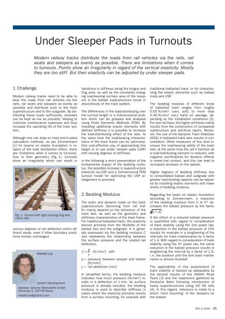
Due to their geometry (Fig. 1), turnouts<br />
show an irregularity which can result <strong>in</strong><br />
Fig. 1: Turnout with rigid cross<strong>in</strong>g frog and<br />
check rails<br />
various degrees of rail deflection with<strong>in</strong> different<br />
areas, even if other boundary conditions<br />
rema<strong>in</strong> unchanged.<br />
Harald Loy<br />
System Development<br />
Address: Getzner Werkstoffe GmbH<br />
Herrenau 5, A-6706 Buers<br />
harald.loy@getzner.com<br />
Variations <strong>in</strong> stiffness along the tongue and<br />
frog area, as well as the constantly chang<strong>in</strong>g<br />
load-bear<strong>in</strong>g surface area of the sleepers<br />
<strong>in</strong> the ballast superstructure result <strong>in</strong><br />
discont<strong>in</strong>uity of the track system.<br />
The differences <strong>in</strong> the load-distribut<strong>in</strong>g over<br />
the turnout length is a 3-dimensional problem<br />
which can be grasped and analyzed<br />
us<strong>in</strong>g F<strong>in</strong>ite Elements Methods (FEM). By<br />
<strong>in</strong>stall<strong>in</strong>g additional elastic elements with<br />
def<strong>in</strong>ed stiffness it is possible to <strong>in</strong>crease<br />
the load-distribut<strong>in</strong>g effect of the rails. At<br />
the same time the load-bear<strong>in</strong>g characteristics<br />
of the track frame can be optimized.<br />
One cost-effective way of approach<strong>in</strong>g this<br />
target is to use under sleeper pads (USP)<br />
with vary<strong>in</strong>g degrees of stiffness.<br />
In the follow<strong>in</strong>g a short presentation of the<br />
fundamental impact of the bedd<strong>in</strong>g modulus,<br />
the possible <strong>in</strong>crease <strong>in</strong> superstructure<br />
elasticity via USP and a 3-dimensional FEM<br />
turnout model for optimiz<strong>in</strong>g the USP arrangement<br />
is provided.<br />
2 Bedd<strong>in</strong>g Modulus<br />
The static and dynamic loads on the track<br />
superstructure stemm<strong>in</strong>g from rail traffic<br />
ma<strong>in</strong>ly depend on the behaviour of the<br />
track bed, as well as the geometry and<br />
stiffness characteristics of the track frame.<br />
For traditional ballasted track, the elasticity<br />
derives primarily from the flexibility of the<br />
ballast bed and the subgrade. It is generally<br />
expressed via the bedd<strong>in</strong>g modulus C<br />
and represents the relationship between<br />
the surface pressure and the related rail<br />
deflection.<br />
C = p<br />
y [N/mm3] with<br />
p = pressure between sleeper and ballast<br />
[N/mm2] y = rail deflection [mm]<br />
In simplified terms, the bedd<strong>in</strong>g modulus<br />
<strong>in</strong>dicates how much pressure [N/mm²] results<br />
<strong>in</strong> a deflection of 1 mm. As surface<br />
pressure is already <strong>in</strong>cluded, the bedd<strong>in</strong>g<br />
modulus is used to describe stiffness <strong>in</strong><br />
cases where the elasticity primarily results<br />
from a surface mount<strong>in</strong>g, for example with<br />
traditional ballasted track, or for characteriz<strong>in</strong>g<br />
flat elastic elements such as ballast<br />
mats and USP.<br />
The bedd<strong>in</strong>g modulus of different k<strong>in</strong>ds<br />
of ballasted track ranges from roughly<br />
0.05 N/mm 3 (very soft) to more than<br />
0.40 N/mm 3 (very hard) on average, depend<strong>in</strong>g<br />
on the <strong>in</strong>stallation conditions [2].<br />
For new rail l<strong>in</strong>es, the higher stiffness ma<strong>in</strong>ly<br />
results from the construction of compacted<br />
substructure and anti-frost layers. Moreover,<br />
the use of the Dynamic Track Stabilizer<br />
(DGS) <strong>in</strong> ballasted track also results <strong>in</strong> consolidation.<br />
While measures of this k<strong>in</strong>d <strong>in</strong>crease<br />
the load-bear<strong>in</strong>g ability of the track<br />
bed, at the same time the rail’s function as<br />
a load-distribut<strong>in</strong>g element is reduced, with<br />
negative ramifications for dynamic effects<br />
<strong>in</strong> wheel/rail contact, and this can lead to<br />
<strong>in</strong>creased stresses on the ballast.<br />
Higher degrees of bedd<strong>in</strong>g stiffness due<br />
to consolidated ballast and subgrade with<br />
greater load-bear<strong>in</strong>g capacity can be adjusted<br />
by <strong>in</strong>stall<strong>in</strong>g elastic elements with lower<br />
levels of bedd<strong>in</strong>g modulus.<br />
Regard<strong>in</strong>g the beam on elastic foundation<br />
accord<strong>in</strong>g to Zimmermann, a reduction<br />
of the bedd<strong>in</strong>g modulus from C to C* decreases<br />
the ballast pressure by the factor<br />
4 C*/C<br />
.<br />
If the effect of a reduced ballast pressure<br />
is quantified with regard to consideration<br />
of track stability us<strong>in</strong>g the 2nd power law,<br />
a reduction <strong>in</strong> the ballast pressure of 15%<br />
results for example <strong>in</strong> a lengthen<strong>in</strong>g of the<br />
<strong>in</strong>tervals for track ma<strong>in</strong>tenance by a factor<br />
of 1.4. With regard to consideration of track<br />
stability us<strong>in</strong>g the 4 th power law, the same<br />
reduction <strong>in</strong> the ballast pressure results <strong>in</strong><br />
lengthen<strong>in</strong>g the <strong>in</strong>terval by a factor of 1.9,<br />
i. e. the duration until the next track ma<strong>in</strong>tenance<br />
is almost doubled!<br />
The applicability of this assessment of<br />
track stability is backed up adequately by<br />
the derived results of the AASHO Road<br />
Tests [3] and the experience gathered by<br />
Deutsche Bahn follow<strong>in</strong>g <strong>in</strong>troduction of<br />
heavy superstructures us<strong>in</strong>g UIC 60 rails<br />
[4]. In this regard, reference is made to a<br />
direct ‘hard mount<strong>in</strong>g’ of the sleepers on<br />
the ballast.<br />
RTR 2/2009 35
36<br />
<strong>Under</strong> <strong>Sleeper</strong> <strong>Pads</strong> <strong>in</strong> <strong>Turnouts</strong><br />
Fig. 2: Concrete sleepers with Sylomer®<br />
under sleeper pads (USP)<br />
In regard to the flexibility of the ballasted<br />
track, the result<strong>in</strong>g bedd<strong>in</strong>g modulus of the<br />
standard gauge track should be set <strong>in</strong> a way<br />
that sufficient rail deflection is ensured,<br />
which should not be less than 1.0 – 1.2 mm<br />
[6], tak<strong>in</strong>g <strong>in</strong>to consideration the load-distribut<strong>in</strong>g<br />
effect <strong>in</strong> the track and the turnouts.<br />
The limit<strong>in</strong>g factor is generally the maximum<br />
permissible amount of rail foot tension.<br />
3 Increas<strong>in</strong>g Superstructure<br />
Elasticity with <strong>Under</strong> <strong>Sleeper</strong><br />
<strong>Pads</strong> (UPS)<br />
USP are a cost-effective way for subsequently<br />
<strong>in</strong>creas<strong>in</strong>g the elasticity of the superstructure<br />
and reduc<strong>in</strong>g wear and tear<br />
on the ballast (Fig. 2). USP are elastic elements<br />
located between the sleeper and the<br />
ballast and are today available <strong>in</strong> a cont<strong>in</strong>uous<br />
range from approximately 0.02 N/mm 3<br />
to harder than 0.30 N/mm 3 for standard<br />
products, Determ<strong>in</strong>ation of bedd<strong>in</strong>g modulus<br />
is given by BN 918 145 – 01 on a prescribed<br />
load plate with ballast profile [5].<br />
The <strong>in</strong>vestment cost is far lower than those<br />
for the <strong>in</strong>stallation of ballast mats. Ballast<br />
mats are ma<strong>in</strong>ly used where direct mount<strong>in</strong>g<br />
to a hard subgrade, e. g. on a bridge,<br />
should to be avoided.<br />
USP does not necessitate the <strong>in</strong>stallation<br />
of elastic railpads. The track frame consist<strong>in</strong>g<br />
of the rails and concrete sleepers,<br />
which is rigidly connected <strong>in</strong>to a load-bear<strong>in</strong>g<br />
structure via the rail fasteners, can thus<br />
rema<strong>in</strong>ed unchanged <strong>in</strong> its traditional role.<br />
stock rails<br />
Fig. 3: Components of a standard right-hand turnout<br />
RTR 2/2009<br />
switch toes<br />
switch<strong>in</strong>g<br />
mach<strong>in</strong>e<br />
switch panel<br />
switch rails<br />
closure rails<br />
switch heels<br />
This is also valid for upgrad<strong>in</strong>g of tracks, as<br />
the costs <strong>in</strong>volved for such work are also<br />
comparatively low.<br />
With ballasted track, elastic USP not only<br />
allow for a longer rail bend<strong>in</strong>g l<strong>in</strong>e, which reduces<br />
loads on the ballast, they also help to<br />
prevent contact abrasion as the top layer of<br />
ballast can become embedded <strong>in</strong> the pads.<br />
Hard contact po<strong>in</strong>ts between the bottom of<br />
the sleeper and the ballast are alleviated<br />
and the track mount<strong>in</strong>g is more homogeneous.<br />
The pads also help to prevent sudden<br />
settl<strong>in</strong>g of sleepers due to cavitations [7].<br />
Due to stabilization of the top ballast layer,<br />
migration of ballast rocks due to dynamic<br />
forces is shifted to lower layers, which can<br />
have a benign effect on the long-term quality<br />
of the superstructure.<br />
Even under the assumption of decl<strong>in</strong><strong>in</strong>g effectiveness<br />
over the effective lifetime of<br />
the rail, USP still cannot result <strong>in</strong> any detrimental<br />
impact on the track superstructure.<br />
In this regard, they can be seen as fail-safe<br />
elements. The track superstructure will always<br />
exhibit more favourable characteristics<br />
than structure without any USP.<br />
There are numerous ways to ensure adequate<br />
adhesion of the pads to the sleepers.<br />
One possibility is to glue the pad to the<br />
cured concrete, but the general trend <strong>in</strong> the<br />
future shows that the pads are <strong>in</strong>tegrated<br />
directly <strong>in</strong>to the sleepers as a part of the<br />
manufactur<strong>in</strong>g process. A tight connection<br />
can be achieved us<strong>in</strong>g a plastic mesh, half<br />
of which is <strong>in</strong>tegrated <strong>in</strong>to the sleeper pad<br />
and the other half of which can be vibrated<br />
<strong>in</strong>to the wet concrete of the sleeper.<br />
Tests <strong>in</strong> Germany have shown that the use<br />
of sleeper pads allows for significantly improved<br />
track behaviour and dynamic vibration<br />
behaviour compared to traditional ballasted<br />
track [8]. In Austria, turnouts with<br />
USP were already <strong>in</strong>stalled <strong>in</strong> 2002 and<br />
measurements have shown a reduction of<br />
vibrations <strong>in</strong> the 40 Hz – 50 Hz frequency<br />
range. Moreover, substantially less subsidence<br />
was found <strong>in</strong> turnouts with rigid cross<strong>in</strong>g<br />
frogs, even compared to constructions<br />
with moveable cross<strong>in</strong>g frogs [9]. The posi-<br />
cross<strong>in</strong>g nose<br />
fl ange way<br />
check rails<br />
w<strong>in</strong>g rails<br />
closure panel cross<strong>in</strong>g panel<br />
through rails<br />
tive experiences with USP <strong>in</strong> turnouts have<br />
led to the development of a standardized<br />
design for the Austrian Federal Railways.<br />
4 Geometrical Discont<strong>in</strong>uities at<br />
<strong>Turnouts</strong><br />
Compared to straight track, for which calculations<br />
are easy to conduct due to the relatively<br />
homogenous geometry with constant<br />
rail profiles and sleeper mount<strong>in</strong>g surfaces,<br />
calculat<strong>in</strong>g elastic elements <strong>in</strong> turnouts is<br />
far more complex. The ma<strong>in</strong> reasons for<br />
higher effort <strong>in</strong>clude the vary<strong>in</strong>g profiles of<br />
the rails, the additional construction elements<br />
and the generally strong variations <strong>in</strong><br />
the sleeper conditions. These parameters<br />
result <strong>in</strong> vary<strong>in</strong>g degrees of vertical load<br />
deflection.<br />
Look<strong>in</strong>g at a standard right-hand turnout,<br />
there is an <strong>in</strong>itial jump <strong>in</strong> stiffness at the<br />
transition po<strong>in</strong>t from the stock rail sleepers,<br />
which are not supposed to be tamped<br />
<strong>in</strong> the middle, to the heavier turnout sleepers<br />
which are often located <strong>in</strong> front of the<br />
switch panel (Fig. 3).<br />
In the switch panel itself, switch<strong>in</strong>g mach<strong>in</strong>es<br />
which are <strong>in</strong>tegrated <strong>in</strong>to hollow<br />
steel sleepers can result <strong>in</strong> additional discont<strong>in</strong>uities.<br />
The switch rails themselves<br />
have an <strong>in</strong>creas<strong>in</strong>g moment of <strong>in</strong>ertia from<br />
the toes to the centre of the turnout. Dur<strong>in</strong>g<br />
passage of the vehicle, while the stock rail<br />
is loaded with one wheel load, the softer<br />
switch rail results <strong>in</strong> a lower distribution of<br />
load when subject to the load from the opposite<br />
wheel load. In the area of the closure<br />
rail, the cont<strong>in</strong>uously grow<strong>in</strong>g sleeper<br />
areas are also noticeable. The massive frog<br />
together with the w<strong>in</strong>g rails results <strong>in</strong> the<br />
greatest stiffness. Due to the check rails<br />
and the long sleepers, the distribution of<br />
the loads is greatest <strong>in</strong> this area. Immediately<br />
after the last long sleeper there are<br />
often eccentrically placed short sleepers<br />
with shortened sleeper heads on the <strong>in</strong>terior<br />
side. This results <strong>in</strong> a strong load on<br />
one side, with correspond<strong>in</strong>g torsion of the<br />
track, depend<strong>in</strong>g on the track design.<br />
The geometrically determ<strong>in</strong>ed discont<strong>in</strong>uity<br />
Fig. 4: FEM turnout model for the optimization<br />
of under sleepers pads
<strong>in</strong> the turnout area causes strong localized<br />
variations <strong>in</strong> the loads on the superstructure.<br />
With a lower bedd<strong>in</strong>g modulus, the<br />
bend<strong>in</strong>g l<strong>in</strong>es can be lengthened which reduces<br />
the amount of pressures on the ballast.<br />
At the same time, by optimiz<strong>in</strong>g the<br />
distribution of the bedd<strong>in</strong>g modulus with<br />
various USP it is possible to smooth out<br />
the differences <strong>in</strong> stiffness stemm<strong>in</strong>g from<br />
the geometry. Thus, careful design and <strong>in</strong>stallation<br />
of various types of sleeper pads<br />
can achieve a double positive effect <strong>in</strong> the<br />
turnout area: Loads on the superstructure<br />
can be reduced and the turnout can be<br />
‘smoothed out'.<br />
5 FEM Turnout Model<br />
It is necessary to understand the entire<br />
system <strong>in</strong> order to be able to transpose the<br />
positive experiences ga<strong>in</strong>ed with padded<br />
sleepers to applications <strong>in</strong>volv<strong>in</strong>g turnouts.<br />
And furthermore to balance out the geometrically<br />
determ<strong>in</strong>ed differences <strong>in</strong> vertical<br />
load distribution. The F<strong>in</strong>ite Elements<br />
Method (FEM) can help us to grasp this<br />
system (Fig. 4).<br />
Us<strong>in</strong>g FEM and high-performance computers,<br />
it is possible to generate a complete<br />
turnout with padded sleepers and to perform<br />
analyses <strong>in</strong> respect of its load-bear<strong>in</strong>g<br />
functions. In contrast to the manual calculation<br />
method accord<strong>in</strong>g to Zimmermann,<br />
there is no need for idealization by transformation<br />
of the entire structure (transverse<br />
sleepers <strong>in</strong> longitud<strong>in</strong>al sleeper superstructure,<br />
resultant stiffness for several elastic<br />
levels). But <strong>in</strong> order to cut calculation<br />
times, the <strong>in</strong>dividual components are reduced<br />
by base elements to their relevant<br />
functionality and the necessary degrees of<br />
freedom. Another advantage of the model is<br />
that variable parameters can be assigned<br />
for all geometries and stiffness <strong>in</strong> the rail<br />
elements (tongue, cross<strong>in</strong>g frog, check<br />
rails, etc.). The same is valid for sleeper<br />
parameters and the non-l<strong>in</strong>ear behaviour of<br />
<br />
<br />
<br />
<br />
<br />
<br />
<br />
<br />
the rail fasteners (rail plate/baseplate function<br />
under pressure loads - fasten<strong>in</strong>g clips<br />
function under tension loads). Moreover,<br />
the behaviour of the bedd<strong>in</strong>g (sleeper pads<br />
and ballast) can be modelled us<strong>in</strong>g any desired<br />
non-l<strong>in</strong>ear deflection curves.<br />
As the <strong>in</strong>dividual elastic levels are not ‘superposed’<br />
by the formation of resultant<br />
spr<strong>in</strong>g stiffness, it is possible to simulate a<br />
division of the flexibility <strong>in</strong> levels above and<br />
below the sleepers. As a result, it is also<br />
possible to <strong>in</strong>dividually observe deformation<br />
variables.<br />
Parameterization of the model allows for<br />
any standard turnout to be generated with<br />
the def<strong>in</strong>ed characteristics and for calculations<br />
to be carried out with a mov<strong>in</strong>g<br />
load collective, correspond<strong>in</strong>g to the load<br />
impact of the bogies. As a result, one obta<strong>in</strong>s<br />
all of the vertical deformation <strong>in</strong> the<br />
<strong>Under</strong> <strong>Sleeper</strong> <strong>Pads</strong> <strong>in</strong> <strong>Turnouts</strong> <br />
Fig. 5: Deflection pattern of the rail through the entire turnout by reduced bedd<strong>in</strong>g modulus step<br />
by step<br />
entire structure (subsidence and rises);<br />
the stra<strong>in</strong>s result from the k<strong>in</strong>ematic conditions<br />
and the parameters of the construction<br />
components. A holistic model of<br />
this nature can be helpful for grasp<strong>in</strong>g the<br />
system compris<strong>in</strong>g the elastically mounted<br />
turnout <strong>in</strong> the ballasted track and mak<strong>in</strong>g<br />
targeted adjustment for the further development<br />
of such.<br />
6 Analysis of Load-Bear<strong>in</strong>g<br />
Behaviour<br />
In order to understand the bedd<strong>in</strong>g impact<br />
on the vertical rail deflection, the stiffness<br />
of the ballast and the subgrade throughout<br />
the entire turnout area is uniformly and<br />
stepwise reduced with<strong>in</strong> the framework of<br />
a simulated calculation. The maximum rail<br />
deflection can therefore be calculated for<br />
each load position, based on the load col-
38<br />
<strong>Under</strong> <strong>Sleeper</strong> <strong>Pads</strong> <strong>in</strong> <strong>Turnouts</strong><br />
Fig. 6: Comparison of rail deflection patterns with optimized track us<strong>in</strong>g different USP along the<br />
turnout<br />
Fig. 7: Reduction of rail seat forces along the turnout with optimized solution<br />
lective for a typical bogie (axle load 220 kN,<br />
3 m spac<strong>in</strong>g). The deflection patterns presented<br />
<strong>in</strong> Fig. 5 represent the envelope for<br />
the maximum vertical deformations of the<br />
relevant rail.<br />
One can see that a lower<strong>in</strong>g of the bedd<strong>in</strong>g<br />
modulus results <strong>in</strong> an <strong>in</strong>crease <strong>in</strong> rail deflection<br />
as desired. But at the same time<br />
the various differences <strong>in</strong> the stiffness can<br />
also be seen along the path of the turnout.<br />
The differences <strong>in</strong> the deformation curves<br />
are magnified. The lower the bedd<strong>in</strong>g modulus<br />
is, the more pronounced the differences<br />
are. In this regard, the amount of deflection<br />
is lowest <strong>in</strong> the cross<strong>in</strong>g frog due to the<br />
higher level of rail stiffness and the large<br />
surface area of the sleepers, whereas immediately<br />
after the last long sleeper.<br />
By optimiz<strong>in</strong>g the arrangement of USP with<br />
vary<strong>in</strong>g degrees of stiffness, these differences<br />
can be smoothed out. Fig. 6 shows a<br />
RTR 2/2009<br />
comparison with an improved arrangement<br />
of stiffness us<strong>in</strong>g various types of USP.<br />
The first curve shows as an example the<br />
deflection curve without any additional USP.<br />
The rail deflection of 0.8 mm <strong>in</strong> the regular<br />
track results exclusively from the def<strong>in</strong>ed<br />
bedd<strong>in</strong>g modulus of the ballast and the subgrade<br />
of 0.2 N/mm 3. If the vertical deformation<br />
is <strong>in</strong>creased by the uniform <strong>in</strong>stallation<br />
of additional under sleeper pads, the result<strong>in</strong>g<br />
bedd<strong>in</strong>g modulus of roughly 0.10 N/mm 3<br />
leads to an <strong>in</strong>crease <strong>in</strong> deflection to<br />
1.3 mm before and after the turnout. The<br />
differences <strong>in</strong> vertical rail deflection can be<br />
smoothed out by the <strong>in</strong>stallation of various<br />
USP, <strong>in</strong> the event of identical <strong>in</strong>itial levels.<br />
This allows for a more homogenous pattern<br />
of deflection to be achieved (us<strong>in</strong>g different<br />
USP types). The turnout is smoothed <strong>in</strong> its<br />
function as a load-bear<strong>in</strong>g element.<br />
Fig. 7 shows the reduction of rail seat forc-<br />
es compared to a turnout without USP. Even<br />
with the relatively stiff pads used <strong>in</strong> this<br />
case (> 0.2 N/mm 3) the forces transmitted<br />
<strong>in</strong>to the superstructure can be reduced on<br />
the order of 10 % to 30 %, depend<strong>in</strong>g on the<br />
part of the turnout.<br />
7 Summary<br />
The use of under sleeper pads (USP) can<br />
<strong>in</strong>crease the elasticity of track superstructure<br />
with relatively low <strong>in</strong>vestment costs. At<br />
the same time the ballast, which is a latent<br />
source of track <strong>in</strong>stability, is stabilized, as<br />
<strong>in</strong>dividual ballast rocks can become embedded<br />
<strong>in</strong> the surface layer of the USP. Loads<br />
on the superstructure are reduced by a<br />
more homogenous mount<strong>in</strong>g of the sleepers<br />
and track stability is improved.<br />
Moreover, <strong>in</strong> turnouts, the geometrically<br />
determ<strong>in</strong>ed differences <strong>in</strong> stiffness can be<br />
smoothed out. To achieve this target, USP<br />
with various degrees of stiffness can be<br />
used, positioned <strong>in</strong> a way that the entire<br />
construction features improved load-bear<strong>in</strong>g<br />
conditions. This allows the track to be<br />
smoother. Track irregularities result<strong>in</strong>g from<br />
turnouts can thus be mitigated and vibrations<br />
can be reduced.<br />
Us<strong>in</strong>g a turnout model based on the F<strong>in</strong>ite<br />
Elements Method, it is possible to analyze<br />
the load-bear<strong>in</strong>g behaviour of the construction.<br />
As data can be varied for different parameters,<br />
it is possible to analyze a very<br />
wide range of geometric boundary conditions<br />
and stiffness conditions. The challenge<br />
<strong>in</strong>volved is to take <strong>in</strong>to consideration<br />
the non-l<strong>in</strong>ear bedd<strong>in</strong>g properties.<br />
Us<strong>in</strong>g the FEM turnout model, an optimized<br />
arrangement of Sylomer ® USP can be calculated<br />
for any situation.<br />
References<br />
[1] Eisenmann, J.: Die Schiene als Träger und Fahrbahn.<br />
Die Eisenbahnschiene (Herausgeber Fastenrath).<br />
Verlag Wilhelm Ernst & Sohn 1977, S.9…78.<br />
[2] Eisenmann, J. und Rump, R.: E<strong>in</strong> Schotteroberbau<br />
für hohe Geschw<strong>in</strong>digkeiten. ETR – Eisenbahntechnische<br />
Rundschau 46, (1997), Heft 3, S.99…108.<br />
[3] AASHO-Road-Test Special Report 61G. Deutsche<br />
Übersetzung <strong>in</strong> Betonstraßenjahrbuch 1962/63,<br />
Beton-Verlag, Düsseldorf.<br />
[4] ORE-Frage D.161, Bericht Nr.4 vom Sept. 1987: Dynamische<br />
Auswirkungen der Anhebung der Radsatzlast<br />
von 20t auf 22,5t und der geschätzte Anstieg<br />
der Oberbauelastizität.<br />
[5] DB Systemtechnik: BN 918145-01: Technische<br />
Lieferbed<strong>in</strong>gungen – Spannbetonschwellen mit elastischer<br />
Sohle – Elastische Schwellensohlen, (Jan.<br />
2004)<br />
[6] Eisenmann, J., Leykauf, G. und Mattner, L.: Vorschläge<br />
zur Erhöhung der Oberbauelastizität. ETR-Eisenbahntechnische<br />
Rundschau 43 (1994). H. 7/8,<br />
S.491…494<br />
[7] Müller-Boruttau, F., Kle<strong>in</strong>ert, U.: Betonschwellen mit<br />
elastischer Sohle, ETR 50 (2001). H3 S. 90-98.<br />
[8] Leykauf, G., Stahl, W.: Untersuchungen und Erfahrungen<br />
mit besohlten Schwellen. EI Der Eisenbahn<strong>in</strong>genieur<br />
(55) 6/2004, S. 8-16.<br />
[9] Schilder, R.: USP <strong>Under</strong> <strong>Sleeper</strong> <strong>Pads</strong> –<br />
Schwellenbesohlungen – E<strong>in</strong> Bericht über bisherige<br />
Erfahrungen, ÖVG Salzburg Congress, Band 65,<br />
Sept. 2004