Operation and Design of Multilevel Inverters Dr ... - MotorLab.com
Operation and Design of Multilevel Inverters Dr ... - MotorLab.com
Operation and Design of Multilevel Inverters Dr ... - MotorLab.com
Create successful ePaper yourself
Turn your PDF publications into a flip-book with our unique Google optimized e-Paper software.
⎡v<br />
⎢<br />
⎢<br />
v<br />
⎢⎣<br />
v<br />
ab<br />
bc<br />
ca<br />
⎤ ⎡ 1<br />
⎥ ⎢<br />
⎥<br />
=<br />
⎢<br />
0<br />
⎥⎦<br />
⎢⎣<br />
−1<br />
−1<br />
0 ⎤⎡v<br />
⎢<br />
−1<br />
⎥<br />
⎥⎢v<br />
1 ⎥⎢<br />
⎦⎣<br />
v<br />
Copyright 2005. K.A. Corzine 4<br />
1<br />
0<br />
ag<br />
bg<br />
cg<br />
⎤<br />
⎥<br />
⎥<br />
⎥<br />
⎦<br />
(3.1-3)<br />
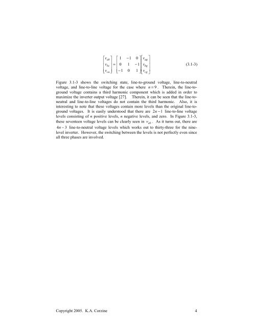
Figure 3.1-3 shows the switching state, line-to-ground voltage, line-to-neutral<br />
voltage, <strong>and</strong> line-to-line voltage for the case where n = 9 . Therein, the line-toground<br />
voltage contains a third harmonic <strong>com</strong>ponent which is added in order to<br />
maximize the inverter output voltage [27]. Therein, it can be seen that the line-toneutral<br />
<strong>and</strong> line-to-line voltages do not contain the third harmonic. Also, it is<br />
interesting to note that these voltages contain more levels than the original line-toground<br />
voltages. It is easily understood that there are 2n −1<br />
line-to-line voltage<br />
levels consisting <strong>of</strong> n positive levels, n negative levels, <strong>and</strong> zero. In Figure 3.1-3,<br />
these seventeen voltage levels can be clearly seen in v ab . As it turns out, there are<br />
4n − 3 line-to-neutral voltage levels which works out to thirty-three for the ninelevel<br />
inverter. However, the switching between the levels is not perfectly even since<br />
all three phases are involved.


