Basic Verilog
Basic Verilog
Basic Verilog

You also want an ePaper? Increase the reach of your titles
YUMPU automatically turns print PDFs into web optimized ePapers that Google loves.
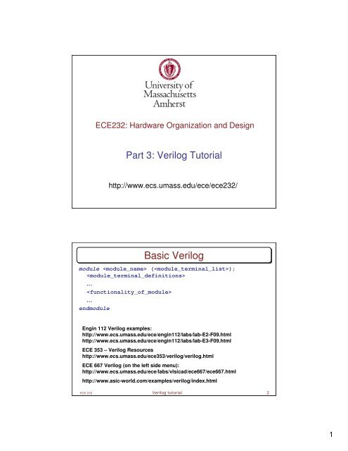
ECE232: Hardware Organization and Design<br />
Part 3: <strong>Verilog</strong> Tutorial<br />
http://www.ecs.umass.edu/ece/ece232/<br />
<strong>Basic</strong> <strong>Verilog</strong><br />
module ();<br />
<br />
…<br />
<br />
…<br />
endmodule<br />
Engin 112 <strong>Verilog</strong> examples:<br />
http://www.ecs.umass.edu/ece/engin112/labs/lab-E2-F09.html<br />
http://www.ecs.umass.edu/ece/engin112/labs/lab-E3-F09.html<br />
ECE 353 – <strong>Verilog</strong> Resources<br />
http://www.ecs.umass.edu/ece353/verilog/verilog.html<br />
ECE 667 <strong>Verilog</strong> (on the left side menu):<br />
http://www.ecs.umass.edu/ece/labs/vlsicad/ece667/ece667.html<br />
http://www.asic-world.com/examples/verilog/index.html<br />
ECE 232 <strong>Verilog</strong> tutorial 2<br />
1
Full Adder<br />
b<br />
module FullAdder(a,b,cin,cout,sum);<br />
input a, b, cin; // inputs<br />
output cout, sum; // output<br />
wire w1, w2, w3, w4; // internal nets<br />
xor #(10) (w1, a, b); // delay time of 10 units<br />
xor #(10) (sum, w1, cin);<br />
and #(8) (w2, a, b);<br />
and #(8) (w3, a, cin);<br />
and #(8) (w4, b, cin);<br />
or #(10, 8)(cout, w2, w3, w4); // (rise time of 10, fall 8)<br />
endmodule<br />
ECE 232 <strong>Verilog</strong> tutorial 3<br />
Multiple ways of implementing Full Adder<br />
module FullAdder(a,b,cin,sum,cout);<br />
input a,b,cin;<br />
output sum, cout;<br />
reg sum, cout; // registers retain value<br />
always @ (a or b or cin) // Anytime a or b or cin<br />
CHANGE, run the<br />
process<br />
begin sum
Ripple Carry Adder<br />
4-bit Adder<br />
module adder4(A, B, cin, S, cout);<br />
input[3:0] A, B;<br />
input cin;<br />
output[3:0] S;<br />
output cout;<br />
wire c1, c2, c3;<br />
// 4 instantiated 1-bit Full Adders<br />
FullAdder fa0(A[0], B[0], cin, c1, S[0]);<br />
FullAdder fa1(A[1], B[1], c1, c2, S[1]);<br />
FullAdder fa2(A[2], B[2], c2, c3, S[2]);<br />
FullAdder fa3(A[3], B[3], c3, cout, S[3]);<br />
endmodule<br />
ECE 232 <strong>Verilog</strong> tutorial 5<br />
HDL Overview<br />
Hardware description languages (HDL) offer a way to design circuits<br />
using text-based descriptions<br />
HDL describes hardware using keywords and expressions.<br />
Representations for common forms<br />
» Logic expressions, truth tables, functions, logic gates<br />
Any combinational or sequential circuit<br />
HDLs have two objectives<br />
Allow for testing/verification using computer simulation<br />
» Includes syntax for timing, delays<br />
Allow for synthesis<br />
» Synthesizable HDL<br />
The two forms often differ !<br />
We will use synthesizable subset of verilog<br />
Two primary hardware description languages<br />
VHDL<br />
<strong>Verilog</strong><br />
ECE 232 <strong>Verilog</strong> tutorial 6<br />
3
Hardware Description Language - <strong>Verilog</strong><br />
° Represents hardware structure and behavior<br />
° Logic simulation: generates waveforms<br />
//HDL Example 1<br />
//--------------------------<br />
module smpl_circuit(A,B,C,x,y);<br />
input A,B,C;<br />
output x,y;<br />
wire e;<br />
and g1(e,A,B);<br />
not g2(y,C);<br />
or g3(x,e,y);<br />
endmodule<br />
° Detect errors before fabrication<br />
ECE 232 <strong>Verilog</strong> tutorial 7<br />
<strong>Verilog</strong> Keywords and Syntax<br />
° Lines that begin with // are comments (ignored by simulation)<br />
° About 100 keywords in total (keywords are case sensitive)<br />
° module: Building block in <strong>Verilog</strong><br />
° Always terminates with endmodule<br />
° module followed by circuit name and port list<br />
° Each port is either an input or output<br />
//HDL Example 2<br />
//-------------------------module<br />
smpl_circuit(A,B,C,x,y);<br />
input A,B,C;<br />
output x,y;<br />
wire e;<br />
and g1(e,A,B);<br />
not g2(y,C);<br />
or g3(x,e,y);<br />
endmodule<br />
ECE 232 <strong>Verilog</strong> tutorial 8<br />
4
<strong>Verilog</strong> Statements<br />
<strong>Verilog</strong> has two basic types of statements<br />
1. Concurrent statements (combinational)<br />
(things are happening concurrently, ordering does not matter)<br />
Gate instantiations<br />
and (z, x, y), or (c, a, b), xor (S, x, y), etc.<br />
Continuous assignments<br />
assign Z = x & y; c = a | b; S = x ^ y<br />
2. Procedural statements (sequential)<br />
(executed in the order written in the code)<br />
always @ - executed continuously when the event is active<br />
always @ (posedge clock)<br />
initial - executed only once (used in simulation)<br />
if then else statements<br />
ECE 232 <strong>Verilog</strong> tutorial 9<br />
wire and gate-level Keywords<br />
• Example of gate instantiation<br />
° wire defines internal circuit connection<br />
° Each gate (and, or, not) defined on a separate line<br />
° Gate I/O includes wires and port values<br />
° Note: each gate is instantiated with a name (e.g., g1)<br />
//HDL Example 2<br />
//--------------------------<br />
module smpl_circuit(A,B,C,x,y);<br />
input A,B,C;<br />
output x,y;<br />
wire e;<br />
and g1(e,A,B);<br />
not g2(y,C);<br />
or g3(x,e,y);<br />
endmodule<br />
ECE 232 <strong>Verilog</strong> tutorial 10<br />
5
Specifying Boolean Expressions<br />
• Example of continuous assignment<br />
//HDL Example 3<br />
//------------------------------<br />
//Circuit specified with Boolean equations<br />
module circuit_bln (x,y,A,B,C,D);<br />
input A,B,C,D;<br />
output x,y;<br />
assign x = A | (B & C) | (~B & C);<br />
assign y = (~B & C) | (B & ~C & ~D);<br />
endmodule<br />
° assign keyword used to indicate<br />
expression<br />
° Assignment takes place continuously<br />
° Note new symbols specific for <strong>Verilog</strong><br />
° OR -> |<br />
° AND -> &<br />
ECE 232<br />
° NOT -> ~<br />
<strong>Verilog</strong> tutorial 11<br />
User Defined Primitives<br />
//HDL Example 4<br />
//-----------------------------------<br />
//User defined primitive(UDP)<br />
primitive crctp (x,A,B,C);<br />
output x;<br />
input A,B,C;<br />
//Truth table for x(A,B,C) = Minterms (0,2,4,6,7)<br />
table<br />
// A B C : x (Note that this is only a comment)<br />
0 0 0 : 1;<br />
0 0 1 : 0;<br />
0 1 0 : 1;<br />
0 1 1 : 0;<br />
1 0 0 : 1;<br />
1 0 1 : 0;<br />
1 1 0 : 1;<br />
1 1 1 : 1;<br />
° Allows definition of truth table<br />
endtable<br />
endprimitive<br />
° Only one output is allowed<br />
ECE 232 <strong>Verilog</strong> tutorial 12<br />
6
More <strong>Verilog</strong> Examples - 1<br />
//HDL Example 5<br />
//----------------------------------------------<br />
//Dataflow description of a 2-to-4-line decoder<br />
module decoder_df (A,B,E,D);<br />
input A,B,E;<br />
output [0:3] D;<br />
assign D[0] = ~(~A & ~B & ~E),<br />
D[1] = ~(~A & B & ~E),<br />
D[2] = ~(A & ~B & ~E),<br />
D[3] = ~(A & B & ~E);<br />
endmodule<br />
° Combinational functionality<br />
° All assignments take place at the same time<br />
° Note declaration of a bus<br />
° output [0:3] D;<br />
ECE 232 <strong>Verilog</strong> tutorial 13<br />
More <strong>Verilog</strong> Examples - 2<br />
//HDL Example 6<br />
//-----------------------------------<br />
//Dataflow description of a 4-bit comparator.<br />
module mag_comp (A,B,ALTB,AGTB,AEQB);<br />
input [3:0] A,B;<br />
output ALTB,AGTB,AEQB;<br />
assign ALTB = (A < B),<br />
AGTB = (A > B),<br />
AEQB = (A == B);<br />
endmodule<br />
° Easy to define arithmetic functionality<br />
° Each comparison creates a single bit result<br />
° Synthesizer automatically converts RTL description to gate-level<br />
description<br />
° RTL = register transfer level<br />
ECE 232 <strong>Verilog</strong> tutorial 14<br />
7
More <strong>Verilog</strong> Examples - 3<br />
• Example of sequential assignment<br />
//HDL Example 7<br />
//---------------------------------<br />
//Behavioral description of 2-to-1-line multiplexer<br />
module mux2x1_bh(A,B,select,OUT);<br />
input A,B,select;<br />
output OUT;<br />
reg OUT;<br />
always @ (select or A or B)<br />
if (select == 1) OUT = A;<br />
else OUT = B;<br />
endmodule<br />
° Conditional statements (if, else) allow for output choices<br />
° always keyword used to indicate action based on variable<br />
change<br />
° Generally conditional statements lead to multiplexers<br />
ECE 232 <strong>Verilog</strong> tutorial 15<br />
Modeling Circuit Delay<br />
° This is for simulation only (not for synthesis)<br />
° Timescale directive indicates units of time for simulation<br />
° ‘timescale 1ns / 100ps<br />
° #(30) indicates an input to output delay for gate g1 of 30 ns<br />
° #(10) indicates an input to output delay for gate g2 of 10 ns<br />
//HDL Example 2<br />
//---------------------------------<br />
//Description of circuit with delay<br />
module circuit_with_delay (A,B,C,x,y);<br />
input A,B,C;<br />
output x,y;<br />
wire e;<br />
and #(30) g1(e,A,B);<br />
or #(20) g3(x,e,y);<br />
not #(10) g2(y,C);<br />
endmodule<br />
ECE 232 <strong>Verilog</strong> tutorial 16<br />
8
HDL Example 8<br />
//Stimulus for simple circuit<br />
module stimcrct;<br />
reg A,B,C;<br />
wire x,y;<br />
circuit_with_delay cwd(A,B,C,x,y);<br />
initial<br />
begin<br />
A = 1'b0; B = 1'b0; C = 1'b0;<br />
#100<br />
° Module circuit_with_delay is<br />
instantiated<br />
° reg keyword indicates that<br />
values are stored (driven)<br />
° Stimulus signals are applied<br />
sequentially<br />
A = 1'b1; B = 1'b1; C = 1'b1; ° $finish indicates simulation<br />
should end<br />
#100 $finish;<br />
end<br />
° Result: collection of waveforms<br />
endmodule<br />
//Description of circuit with delay<br />
// NOT synthesizable !<br />
module circuit_with_delay (A,B,C,x,y);<br />
input A,B,C;<br />
output x,y;<br />
wire e;<br />
and #(30) g1(e,A,B);<br />
or #(20) g3(x,e,y);<br />
not #(10) g2(y,C);<br />
endmodule<br />
ECE 232 <strong>Verilog</strong> tutorial 17<br />
° Timescale directive indicates<br />
units of time for simulation<br />
° ‘timescale 1ns / 100ps<br />
° Note that input values change at<br />
100ns<br />
° Shaded area at left indicates<br />
output values are undefined<br />
Test bench Stimulus - 1<br />
Test bench Stimulus - 2<br />
ECE 232 <strong>Verilog</strong> tutorial 18<br />
9
Modeling Sequential Elements<br />
module D-latch (D, Clk, Q);<br />
endmodule<br />
input D, Clk;<br />
output Q;<br />
reg Q;<br />
always @(D or Clk)<br />
if (Clk)<br />
Q = D;<br />
D<br />
Clk<br />
Q$latch<br />
PRE<br />
D Q<br />
ENA<br />
CLR<br />
ECE 232 <strong>Verilog</strong> tutorial 19<br />
module D-flipflop (D, Clk, Q);<br />
input D, Clk;<br />
output Q;<br />
reg Q;<br />
<strong>Verilog</strong> – D Flip-flop<br />
always @(posedge Clk)<br />
Q = D;<br />
endmodule Q~reg0<br />
D<br />
Clk<br />
D Latch<br />
ECE 232 <strong>Verilog</strong> tutorial 20<br />
D<br />
PRE<br />
Q<br />
ENA<br />
CLR<br />
Q<br />
Q<br />
10
<strong>Verilog</strong> - Blocking Assignment (=)<br />
module DFF-blocking(D, Clock, Q1, Q2);<br />
input D, Clock;<br />
output Q1, Q2;<br />
reg Q1, Q2;<br />
D<br />
Clock<br />
always @(posedge Clock)<br />
begin<br />
// blocking assignment – series<br />
execution<br />
Q1 = D;<br />
Q2 = Q1;<br />
end<br />
endmodule<br />
Q1~reg0<br />
PRE<br />
D Q<br />
Q2~reg0<br />
PRE<br />
D Q<br />
ECE 232 <strong>Verilog</strong> tutorial 21<br />
<strong>Verilog</strong> – Non-blocking Assignment (
<strong>Verilog</strong> – D Flip-flop with Reset<br />
• D flip-flop with asynchronous reset (asserted negative)<br />
module dff_reset(D, Clock, Resetn, Q);<br />
input D, Clock, Resetn;<br />
output Q;<br />
reg Q;<br />
always @(negedge Resetn or posedge<br />
Clock)<br />
if (!Resetn)<br />
Q
State diagrams are<br />
representations of Finite<br />
State Machines (FSM)<br />
Mealy FSM<br />
Output depends on input and<br />
state<br />
Output is not synchronized<br />
with clock<br />
» can have temporarily<br />
unstable output<br />
Moore FSM<br />
Finite State Machines - 2<br />
Output depends only on state<br />
Moore<br />
FSM<br />
Mealy<br />
FSM<br />
ECE 232 <strong>Verilog</strong> tutorial 25<br />
Example 1: Sequence Detector<br />
Circuit specification:<br />
Design a circuit that outputs a 1 when three consecutive<br />
1’s have been received as input and 0 otherwise.<br />
FSM type<br />
Moore or Mealy FSM?<br />
» Both possible<br />
» Chose Moore to simplify diagram<br />
State diagram:<br />
» State S0: zero 1s detected<br />
» State S1: one 1 detected<br />
» State S2: two 1s detected<br />
» State S3: three 1s detected<br />
ECE 232 <strong>Verilog</strong> tutorial 26<br />
13
Sequence Detector: <strong>Verilog</strong> (Moore FSM)<br />
module seq3_detect_moore(x,clk, y);<br />
// Moore machine for a three-1s sequence detection<br />
input x, clk;<br />
output y;<br />
reg [1:0] state;<br />
parameter S0=2'b00, S1=2'b01, S2=2'b10,<br />
S3=2'b11;<br />
// Define the sequential block<br />
always @(posedge clk)<br />
case (state)<br />
S0: if (x) state
Sequence Detector: <strong>Verilog</strong> (Mealy FSM)<br />
module seq3_detect_mealy(x,clk, y);<br />
// Mealy machine for a three-1s sequence detection<br />
input x, clk;<br />
output y;<br />
reg y;<br />
reg [1:0] pstate, nstate; //present and next states<br />
parameter S0=2'b00, S1=2'b01, S2=2'b10, S3=2'b11;<br />
// Next state and output combinational logic<br />
// Use blocking assignments "="<br />
always @(x or pstate)<br />
case (pstate)<br />
S0: if (x) begin nstate = S1; y = 0; end<br />
else begin nstate = S0; y = 0; end<br />
S1: if (x) begin nstate = S2; y = 0; end<br />
else begin nstate = S0; y = 0; end<br />
S2: if (x) begin nstate = S3; y = 0; end<br />
else begin nstate = S0; y = 0; end<br />
S3: if (x) begin nstate = S3; y = 1; end<br />
else begin nstate = S0; y = 0; end<br />
endcase<br />
// Sequential logic, use nonblocking assignments "
Example 2: Vending Machine FSM - 1<br />
Specify the Problem<br />
Deliver package of gum after 15 cents deposited<br />
Single coin slot for dimes, nickels<br />
No change<br />
Design the FSM using combinational logic and flip flops<br />
Coin<br />
Sensor<br />
N<br />
D<br />
Reset<br />
Clk<br />
Vending<br />
Machine<br />
FSM<br />
Open<br />
Gum<br />
Release<br />
Mechanism<br />
ECE 232 <strong>Verilog</strong> tutorial 31<br />
Example 2: Vending Machine FSM - 2<br />
State diagram<br />
Reset<br />
D<br />
N<br />
N<br />
N, D<br />
0¢<br />
5¢<br />
10¢<br />
15¢<br />
[open]<br />
Reuse states<br />
whenever possible<br />
D<br />
Present<br />
State<br />
Symbolic State Table<br />
ECE 232 <strong>Verilog</strong> tutorial 32<br />
0¢<br />
5¢<br />
10¢<br />
15¢<br />
Inputs Next<br />
D N State<br />
0<br />
0<br />
1<br />
1<br />
0<br />
0<br />
1<br />
1<br />
0<br />
0<br />
1<br />
1<br />
X<br />
0<br />
1<br />
0<br />
1<br />
0<br />
1<br />
0<br />
1<br />
0<br />
1<br />
0<br />
1<br />
X<br />
0¢<br />
5¢<br />
10¢<br />
X<br />
5¢<br />
10¢<br />
15¢<br />
X<br />
10¢<br />
15¢<br />
15¢<br />
X<br />
15¢<br />
Output<br />
Open<br />
0<br />
0<br />
0<br />
X<br />
0<br />
0<br />
0<br />
X<br />
0<br />
0<br />
0<br />
X<br />
1<br />
16
Vending Machine: <strong>Verilog</strong> (Moore FSM)<br />
module vending_moore(N, D, clk, reset, open);<br />
// Moore FSM for a vending machine<br />
input N, D, clk, reset;<br />
Synthesizing Moore FSM directly from state diagram<br />
output open;<br />
reg [1:0] state;<br />
parameter S0=2'b00, S5=2'b01, S10=2'b10,<br />
S15=2'b11;<br />
// Define the sequential block<br />
always @(posedge reset or posedge clk)<br />
if (reset) state
Moore FSM<br />
Mealy FSM<br />
Vending Machine: Simulation Results<br />
ECE 232 <strong>Verilog</strong> tutorial 35<br />
Summary<br />
Hardware description languages provide a valuable tool<br />
for computer engineers<br />
Any logic circuit (combinational or sequential) can be<br />
represented in HDL<br />
Circuits created using keywords and syntax<br />
Possible to use timing information<br />
Explicit delay (#) is for simulation purposes only<br />
Circuits with delays are not synthesizable<br />
Gate and RTL descriptions are possible<br />
<strong>Verilog</strong> is widely used in industry<br />
ECE 232 <strong>Verilog</strong> tutorial 36<br />
18