Fourier Analysis - Redes de Computadores - UPV
Fourier Analysis - Redes de Computadores - UPV
Fourier Analysis - Redes de Computadores - UPV
Create successful ePaper yourself
Turn your PDF publications into a flip-book with our unique Google optimized e-Paper software.
Laboratory<br />
2<br />
<strong>Fourier</strong> <strong>Analysis</strong><br />
Study of the distortion produced by a physical transmission<br />
medium on the transmission of a digital signal.<br />
Objetive<br />
<strong>Fourier</strong> analysis is a fundamental concept that allows the un<strong>de</strong>rstanding the distortion<br />
effects suffered by a digital signal injected in a physical transmission medium (i.e.<br />
copper wires). With this lab session, you will learn how a digital signal may be<br />
<strong>de</strong>composed in a sum of basis functions (sines and cosines) by using <strong>Fourier</strong> series.<br />
Also, you will be able to recognize the impact of transmission medium characteristics<br />
over the signal received at the other end.<br />
Overview<br />
When a signal is <strong>de</strong>livered through a physical transmission medium, a sort of different<br />
phenomena may introduce perturbation on the signal (i.e. attenuation, noise, etc.). Some<br />
of these effects may be observed in the time domain, however other effects are better<br />
analysed in the frequency domain. So, we are going to introduce <strong>Fourier</strong> analysis as a<br />
math tool for study and analyze the transmitted digital signal..<br />
<strong>Fourier</strong> Fundamentals.<br />
In this section we are going to introduce some theoretical concepts about <strong>Fourier</strong><br />
<strong>de</strong>composition. For more information, refer to course documentation.<br />
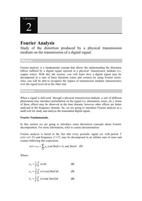
<strong>Fourier</strong> analysis is based in the fact that every periodic signal s(t) with period T<br />
(s(t)=s(t+T)) and frequency f=1/T, may be <strong>de</strong>composed in an infinite sum of sines and<br />
cosines following this expression:<br />
Where:<br />
∑ ∞<br />
n=<br />
1<br />
s( t)<br />
= a + a cos( 2π<br />
nft)<br />
+ b sen( 2πnft)<br />
(1)<br />
a<br />
a<br />
b<br />
0<br />
n<br />
n<br />
1<br />
=<br />
T<br />
2<br />
=<br />
T<br />
2<br />
=<br />
T<br />
0<br />
∫<br />
T<br />
0<br />
∫<br />
∫<br />
T<br />
0<br />
T<br />
0<br />
n<br />
s(<br />
t)<br />
dt<br />
n<br />
(2)<br />
s(<br />
t)<br />
cos( 2π<br />
nft)<br />
dt (3)<br />
s(<br />
t)<br />
sen( 2π<br />
nft)<br />
dt (4)
In expression (1), f is the fundamental frequency of signal s(t). At the other hand, a0 is a<br />
constant, we call DC component of signal s(t), that is calculated with expression (2).<br />
The rest of terms in (1) correspond to the infinite components of signal s(t), we call<br />
them harmonics or frequencial components. So, the n-th harmonic of signal s(t) is given<br />
by the following expression<br />
sn n<br />
n<br />
( t)<br />
= a cos( 2π<br />
nft)<br />
+ b sen( 2πnft)<br />
(5)<br />
Related to (5), if nf=1, then cos( 2π<br />
t) + sen( 2πt)<br />
corresponds with the sum of one sine<br />
and cosine of period 1. So, nf components <strong>de</strong>fine the sine and cosine frequency. As a<br />
consequence, the frequency of n-th harmonic will be f n = nf<br />
Finally, the amplitu<strong>de</strong> of a sine (or cosine) of n harmonic is given by coefficients an and<br />
bn. These coefficients weight the contribution of the corresponding harmonic in the<br />
original signal s(t), and are calculated by mean of expressions (3) and (4). The power or<br />
amplitu<strong>de</strong> of harmonic n may be calculated as:<br />
P = a + b<br />
(6)<br />
n<br />
2<br />
n<br />
2<br />
n<br />
The graphical representation of all harmonics of original signal in the frequency domain<br />
is known as spectral domain of signal s(t). Latter, we will show some examples.<br />
Impact of physical medium in signal transmission<br />
When using a wire for transmitting a signal, the resulting signal at the other end is<br />
received as a attenuated version of the original signal. However, in the frequency<br />
domain, not all harmonics are uniform attenuated. The resulting behaviour is similar to<br />
a low-pass filter, where low frequency harmonics cross the filter without attenuation,<br />
but as harmonic frequency increase they are more attenuated and even filtered.<br />
So, we will consi<strong>de</strong>r that a physical transmission medium transport all signal harmonics<br />
with frequency inferior to fc (cut frequency), and the rest of signal harmonics are totally<br />
filtered. This assumption is not realistic because there is a progressive attenuation of<br />
harmonics up to the cut frequency. Anyway, un<strong>de</strong>r the above assumption we can say<br />
that a physical transmission medium has a bandwidth BW corresponding to the<br />
maximum frequency it is able to transport (fc).<br />
A digital signal is ma<strong>de</strong> up of an infinite number of harmonics. This implies that we<br />
would need an infinite bandwidth channel for transmitting the signal without distortion.<br />
Unfortunately, there is no physical medium with infinite bandwidth, so in practice the<br />
received signal will be a distorted version from the original one (not all harmonics will<br />
be received).<br />
It is obvious that as more harmonics be received the reconstructed signal will have<br />
better quality. However, not all harmonics contribute in the same manner to the<br />
reconstruction of the signal. IN particular, the first harmonics carry the most part of the<br />
2
total signal power. So, we have to <strong>de</strong>termine the minimum number of harmonics<br />
required by the received to recognize and reconstruct the signal.<br />
How to compute the <strong>Fourier</strong> series of an ASCII character.<br />
Suppose that we are going to continuously transmit one character (one byte). If T is the<br />
repetition period, we can formally <strong>de</strong>fine the transmitted signal s(t) as:<br />
⎧<br />
⎡ T ⎡<br />
⎪ bit( 0)<br />
when t ∈ ⎢0<br />
+ Tn,<br />
+ Tn⎢<br />
⎪<br />
⎣ 8 ⎣<br />
⎪<br />
⎡T<br />
2T<br />
⎡<br />
s(<br />
t)<br />
=<br />
bit( 1)<br />
when t ∈<br />
⎨<br />
⎢ + Tn,<br />
+ Tn⎢<br />
⎣8<br />
8 ⎣<br />
⎪<br />
M<br />
⎪<br />
⎪<br />
⎡7T<br />
⎡<br />
bit( 7)<br />
whent<br />
∈<br />
⎪<br />
⎢ + Tn,<br />
T + Tn⎢<br />
⎩<br />
⎣ 8<br />
⎣<br />
∀n∈<br />
?<br />
(7)<br />
Where bit(i) are constants that <strong>de</strong>fine the value of bit i (of transmitted character).<br />
If the signal is not periodic, we can not use <strong>Fourier</strong> Series, instead we are obliged to use<br />
the <strong>Fourier</strong> transform which is out of the course scope.<br />
Now, we are ready to calculate the terms a0, an and bn <strong>de</strong> (1) for the signal <strong>de</strong>fined in<br />
(7). So, we are going to use the equations (2), (3) and (4).<br />
Let start with the DC component a0,<br />
a<br />
0<br />
1<br />
=<br />
T<br />
∫<br />
T<br />
0<br />
s(<br />
t)<br />
dt<br />
As function s(t) is <strong>de</strong>fined as (7), we can perform the integral calculation by intervals:<br />
a<br />
0<br />
T<br />
2T<br />
1<br />
⎛<br />
⎜ 8<br />
8<br />
= bit ( 0)<br />
dt + bit ( 1)<br />
dt + K +<br />
⎜∫<br />
∫T<br />
T 0<br />
∫<br />
⎝<br />
8<br />
3<br />
T<br />
7T<br />
8<br />
⎞<br />
bit ( 7)<br />
dt⎟<br />
⎟<br />
⎠<br />
Remember that bit(i) are constants, so we can consi<strong>de</strong>r the following<br />
a<br />
0<br />
T<br />
2T<br />
1<br />
⎛<br />
⎜ 8<br />
8<br />
= bit ( 0)<br />
dt + bit ( 1)<br />
dt + K + bit ( 7)<br />
⎜ ∫ ∫T<br />
T<br />
0<br />
∫<br />
⎝<br />
8<br />
Solving the simple integral<br />
and<br />
a<br />
0<br />
1 ⎛<br />
= ⎜bit<br />
( 0)<br />
T ⎜<br />
⎝<br />
T<br />
2T<br />
[ t]<br />
8 + bit ( 1)<br />
[ t]<br />
8 + K + bit ( 7)<br />
[ t]<br />
0<br />
1 ⎛ T T<br />
T<br />
a0 = ⎜ bit ( 0)<br />
+ bit ( 1)<br />
+ K<br />
+ bit ( 7)<br />
T ⎝ 8 8<br />
8<br />
T<br />
8<br />
⎞<br />
⎟<br />
⎠<br />
T<br />
7T<br />
8<br />
T<br />
7T<br />
8<br />
⎞<br />
⎟<br />
⎟<br />
⎠<br />
⎞<br />
dt⎟<br />
⎟<br />
⎠
Finally, after removing T, we can observe that the DC component is in<strong>de</strong>pen<strong>de</strong>nt from<br />
signal period (T), in other words, it is in<strong>de</strong>pen<strong>de</strong>nt from transmission speed. We can<br />
<strong>de</strong>fine a0 as<br />
7<br />
∑<br />
i=<br />
0<br />
1<br />
a 0 = bit ( i)<br />
(8)<br />
8<br />
The DC component a0 of signal s(t) is the arithmetic mean of all its bits.<br />
The an and bn calculation can be done in a similar way, using equations (3) and (4). The<br />
result, you have to perform the <strong>de</strong>velopment by yourself, is<br />
a<br />
b<br />
n<br />
n<br />
1<br />
=<br />
nπ<br />
1<br />
=<br />
nπ<br />
7<br />
∑<br />
i=<br />
0<br />
7<br />
∑<br />
i=<br />
0<br />
⎡ ⎛ ⎛ nπ<br />
⎞ ⎛ nπ<br />
⎞⎞⎤<br />
⎢bit(<br />
i)<br />
⎜ sen⎜<br />
( i + 1)<br />
⎟ − sen⎜<br />
i ⎟⎟⎥<br />
⎣ ⎝ ⎝ 4 ⎠ ⎝ 4 ⎠⎠⎦<br />
⎡ ⎛ ⎛ nπ<br />
⎞ ⎛ nπ<br />
⎞⎞⎤<br />
⎢bit(<br />
i)<br />
⎜cos⎜<br />
i⎟<br />
− cos⎜<br />
( i + 1)<br />
⎟⎟⎥<br />
⎣ ⎝ ⎝ 4 ⎠ ⎝ 4 ⎠⎠⎦<br />
sen(<br />
kt)<br />
cos( kt)<br />
Clue: Notice that cos( kt)<br />
dt = ∫<br />
and sen(<br />
kt)<br />
dt = −<br />
k ∫ k<br />
Procedure<br />
Firstly, we are going to <strong>de</strong>velop in C source co<strong>de</strong> the computation of coefficients a0, an<br />
and bn by means of expressions (8), (9) and (10). Then, we will analyze the graphical<br />
representation of the transmitted character .<br />
Required resources<br />
We supply a uncompleted C source file “<strong>Fourier</strong>.cpp”. Also we require a C compiler.<br />
We may use whatever ANSI C compiler (MS Visual C/C++, Borland C/C++, gnu C++,<br />
etc.). In particular, we suggest the use of GNU C++ compiler, gcc, bundled with<br />
Unix/Linux distributions.<br />
The software corresponds with a console program that calculates the <strong>Fourier</strong> series<br />
analysis. If we prefer using other compilers as MS Visual C++ or Borland C/C++, it is<br />
necessary to create a new Console Proyect and add the source file <strong>Fourier</strong>.cpp to it.<br />
In or<strong>de</strong>r to represent the reconstructed signal (in time and frequency domains), we need<br />
a drawing application. We propose the use of GNUPlot (version 3.6 or later). GNUPlot<br />
is a multiplatform software available in near all Linux distributions and other platforms<br />
like Windows (gp373w32.zip).<br />
In Hero<strong>de</strong>s server, \\hero<strong>de</strong>s.re<strong>de</strong>s.upv.es\practicas\re<strong>de</strong>sFI\<strong>Fourier</strong>, we supply all<br />
the required resources for this lab. Also, you can find a binary version of <strong>Fourier</strong><br />
program for both Linux (<strong>Fourier</strong>) and Windows (<strong>Fourier</strong>.exe) systems.<br />
4<br />
(9)<br />
(10)
Execution example<br />
Before start programming, we will show an example of the output generated by the<br />
available solution. So, copy the binary file to a local temporal directory. Then, open a<br />
system console window and run the program without specifying command line<br />
arguments. The <strong>de</strong>fault parameters are fixed to a pre<strong>de</strong>fined character, transmission<br />
speed and channel bandwidth.<br />
The generated output is composed by two files: An ASCII file “armonico.txt” that<br />
contains the frequency (in Hertzs) and power of the harmonics that cross the channel,<br />
and a GNUPlot script file with the commands required for drawing the original signal<br />
(input signal), the signal received at the other channel end (output signal), and the<br />
frequency domain of the latter signal.<br />
The resulting GNUPlot script file should be the following:<br />
# REDES DE COMPUTADORES - FACULTAD DE INFORMATICA DE VALENCIA<br />
# PRACTICA SOBRE ANALISIS DE SEÑALES MEDIANTE SERIES DE FOURIER<br />
reset<br />
set size 1.0, 1.0<br />
set label "- Caracter: 97 'a' (61h)\n\n- Vel. txon: 1200 bps\n --> Duracion<br />
<strong>de</strong> un bit:\n 0.8333 ms \n --> Periodo <strong>de</strong> un byte:\n 6.6667 ms \n -<br />
-> Frec. fundamental:\n 150.00 Hz \n\n- Ancho <strong>de</strong> banda <strong>de</strong>l medio \n(i<strong>de</strong>al):<br />
1000.00 Hz\n --> Numero <strong>de</strong> armonicos\n pasantes: 6\n\n"at screen 0.7,0.8<br />
left<br />
set multiplot<br />
set nokey<br />
set size 0.7, 0.5<br />
set origin 0.0, 0.5<br />
set yrange [-0.5:1.5]<br />
set ylabel "Amplitud"<br />
set xlabel "Tiempo (seg)"<br />
f=150.000000<br />
# Funcion que <strong>de</strong>fine el byte original que se transmite<br />
byte(x)=(x
Alter that, s(x) is <strong>de</strong>fined as the sum of six harmonics s1(x)… s6(x) that cross the<br />
channel. In or<strong>de</strong>r to calculate the a0, an and bn coefficients, the program implements<br />
several functions that we have to <strong>de</strong>velop a bit latter.<br />
Finally, The firs plot command draws functions byte(x) and s(x) in overlapped manner,<br />
while the second plot command draws the frequency components of s(x) by using the<br />
information inclu<strong>de</strong>d in “armonico.txt”.<br />
For more information about GNUPlot commands check the internal help system (help<br />
command).<br />
Now, we are ready to produce the curves, so we have to:<br />
1. Check if the execution attribute of <strong>Fourier</strong> binary is activated. If not, use the<br />
chmod command: chmod +x <strong>Fourier</strong><br />
2. Introduce ./<strong>Fourier</strong> > comandos.txt in or<strong>de</strong>r to redirect the Standard output to<br />
an ASCII file. This file will be the GNUPlot script file.<br />
3. Next, we call GNUPlot tool passing it the script file generated just before<br />
(introduce gnuplot comandos.txt)<br />
GNUPlot will show the following window:<br />
6
In the right, the required information to perform the <strong>Fourier</strong> analysis is shown (The<br />
transmitted character, transmission speed and channel bandwidth (BW). Also additional<br />
info is presented as the time of one bit, the signal period, the fundamental frequency and<br />
the number of passing harmonics.<br />
In the top of the window the input signal (in blue) an the output signal (received signal)<br />
are shown. The input and output signals are <strong>de</strong>fined by byte(x) and s(x) functions,<br />
respectively.<br />
In the bottom, the frequency domain of the received signal is shown. Every harmonic is<br />
represented by a vertical red line. The position of each harmonic in the X-axis<br />
represents its frequency and its amplitu<strong>de</strong> corresponds with the power of this harmonic.<br />
We can observe that channel bandwidth is marked by a vertical blue arrow, just on the<br />
cut frequency (fc).<br />
Programming section: How to compute the a0, an and bn coefficients.<br />
Firstly, you have to edit the <strong>Fourier</strong>.cpp file and take a first look. The first functions<br />
have only <strong>de</strong>fined their hea<strong>de</strong>r, being their body empty:<br />
double a(int n, int caracter)<br />
{<br />
// IMPLEMENTAR<br />
}<br />
double b(int n, int caracter)<br />
{<br />
// IMPLEMENTAR<br />
}<br />
double a0(int caracter)<br />
{<br />
// IMPLEMENTAR<br />
}<br />
The two first functions are the ones that calculate the an and bn coefficients. For that<br />
purpose, use the equations (9) and (10), where the input argument, n, specifies the<br />
harmonic or<strong>de</strong>r. Using the following expression bit(caracter,i) you can get the value of<br />
bit(i). The third function is about the a0 calculation which can be done through the use<br />
of expression (8). In or<strong>de</strong>r to return the results in all these functions you have to use the<br />
return command.<br />
Alter implementing the above functions, we will <strong>de</strong>bug the program and verify its<br />
correctness. To call compiler in Linux:<br />
gcc <strong>Fourier</strong>.cpp –o Mi<strong>Fourier</strong> –lm<br />
7
With –o option we specify the name of the resulting binary file. The –lm option is<br />
necessary to link with math library (sin and cos trigonometric functions)<br />
Impact of physical medium on the transmitted signal.<br />
Here we are going to use our program to analyze how the transmitted signal is distorted<br />
when crossing an specific transmission channel. For that purpose, we are going to<br />
produce four different scenarios corresponding with the transmission of one signal with<br />
the same transmission speed un<strong>de</strong>r different channel bandwidths. In particular, we will<br />
use channels with bandwidths of 400, 1000, 2000 and 9000 Hz.<br />
Run the program with the following parameters:<br />
./Mi<strong>Fourier</strong> –c a –v 1200 –b 400 –a 10000 > bw400.txt<br />
Option –c specifies the character we are going to transmit (also we can specify the<br />
ASCII co<strong>de</strong>: –c 97). Option –v fixes the transmission speed (in bits per second). With<br />
option --b we can <strong>de</strong>fine the <strong>de</strong>sired channel bandwidth. Finally, option –a is aesthetic<br />
option used to <strong>de</strong>termine width of the frequency domain plot (in Hz).<br />
As the character and transmission speed are just the same than the <strong>de</strong>fault ones, we do<br />
not need to specify them. Run the program to get results for the rest of proposed<br />
bandwidths.<br />
./Mi<strong>Fourier</strong> –b 1000 –a 10000 > bw1000.txt<br />
./Mi<strong>Fourier</strong> –b 2000 –a 10000 > bw2000.txt<br />
./Mi<strong>Fourier</strong> –b 9000 –a 10000 > bw9000.txt<br />
Compare the four graphics, using the GNUPlot program. You can observe that as<br />
bandwidth increases, more harmonics cross the channel and as a consequence the<br />
reconstructed signal is better (closer to the original one). Do you think that a bandwidth<br />
of 400 Hz is enough for transmitting this character with a speed of 1.200 bps. ? Should<br />
it be necessary a channel bandwidth of 9 KHz or it would be enough with 2 KHz?<br />
Impact of transmission speed on the transmitted signal<br />
En general, todos tenemos la i<strong>de</strong>a <strong>de</strong> que al transmitir por un medio físico una señal<br />
digital, la velocidad máxima <strong>de</strong> transmisión está acotada. Hay muchos factores que<br />
introducen esta limitación, pero uno <strong>de</strong> los principales es que el ancho <strong>de</strong> banda <strong>de</strong>l<br />
medio es limitado. Como ya hemos visto, esto provoca que a partir <strong>de</strong> una <strong>de</strong>terminada<br />
frecuencia, el resto <strong>de</strong> armónicos se atenúan.<br />
We can notice that transmission speed is very related with signal period T. So that, as<br />
transmission speed increases the signal period becomes shorter. The fundamental<br />
frequency that <strong>de</strong>termines the distance between harmonics also increases, so a lower<br />
number of harmonics will cross the channel and, as a consequence, the reconstructed<br />
signal will be poorer .<br />
8
To verify this effect we will use our program with the following transmission speeds<br />
1200, 2400, 4800 and 9600 bps, and a fixed channel bandwidth of 6 KHz.<br />
./Mi<strong>Fourier</strong> –b 6000 –a 10000 –v 1200 > v1200.txt<br />
./Mi<strong>Fourier</strong> –b 6000 –a 10000 –v 2400 > v2400.txt<br />
./Mi<strong>Fourier</strong> –b 6000 –a 10000 –v 4800 > v4800.txt<br />
./Mi<strong>Fourier</strong> –b 6000 –a 10000 –v 9600 > v9600.txt<br />
Analyze the results shown in the four resulting graphics. The difference between them<br />
stay on the distance between two consecutive harmonics. So, when the transmission<br />
speed increases the number of harmonics that arrive at the other end <strong>de</strong>creases. Is it<br />
acceptable a transmission speed of 9600 bps for this physical channel ?<br />
In general, is not obvious to <strong>de</strong>termine the maximum transmission speed for a particular<br />
physical channel. In theory, we can say that the maximum transmission speed will be<br />
the one that allows crossing the channel the enough harmonics to properly reconstruct<br />
the signal at the other end. This would be true in this example when the first six<br />
harmonics cross the channel.<br />
Next, use the program to transmit a character using a channel with a 6 KHz. bandwidth<br />
and a transmission speed of 7600 bps. Then, do the same with a channel of 45 KHz.<br />
bandwidth and a transmission speed of 56000 bps. Is there any difference between both<br />
reconstructed signals? What do you think is more important channel bandwidth,<br />
transmission speed o the relation between both ? Justify the answers.<br />
Problem<br />
We have a physical channel that behaves as an i<strong>de</strong>al low-pass filter with a 10 KHz.<br />
bandwidth (0..10 KHz.). We continuously transmit a signal composed of an ASCII<br />
character (whatever char) of 8 bits with a transmission speed of 1000 bps. How many<br />
harmonics cross the channel? I<strong>de</strong>m if transmission speed is 2000 bps ?. Solve the<br />
problem analytically, and then run program to verify the results.<br />
Analytic solution: The signal period covers the eight character bits. If transmission<br />
speed is 1000 bps, then one bit lasts 1 ms, and T = 8 ms. The fundamental frequency<br />
(the inverse of period) will be f = 1/0,008 = 125 Hz. If the channel bandwidth is 10000<br />
Hz, the number of passing harmonics will be (10000 / 125) = 80. If transmission speed<br />
doubles, the fundamental frequency also doubles (250 Hz) and the number of harmonics<br />
will be just the half (40).<br />
Additional questions<br />
One interesting improvement to the program will be the following: Allow a physical<br />
channel with a band-pass behaviour like the local-loop phone lines (with a passing band<br />
between 300 and 3300 Hz.)<br />
Another proposed addition is mo<strong>de</strong>lling the channel taking in a more realistic approach.<br />
So harmonics will be attenuated from one frequency fa up to the cut frequency fc. To<br />
perform this change, find the attenuation tables (as a function of frequency) for different<br />
wire categories, and apply the attenuation over a specified number of harmonics (i.e. the<br />
9
first 100 harmonics). If you do not find these tables, you can build them from the<br />
attenuation graphics shown in lecture sli<strong>de</strong>s (signal theory topic).<br />
10


