

Exodermic™ Brochure - Exodermic™ Bridge Deck
Exodermic™ Brochure - Exodermic™ Bridge Deck
Exodermic™ Brochure - Exodermic™ Bridge Deck

You also want an ePaper? Increase the reach of your titles
YUMPU automatically turns print PDFs into web optimized ePapers that Google loves.
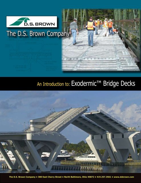
The D.S. Brown Company<br />
An Introduction to: Exodermic <strong>Bridge</strong> <strong>Deck</strong>s<br />
The D.S. Brown Company • 300 East Cherry Street • North Baltimore, Ohio 45872 • 419.257.3561 • www.dsbrown.com
Exodermic Overview<br />
An Exodermic (or “composite, unfilled steel grid”) deck is comprised of<br />
a reinforced concrete slab on top of, and composite with, an unfilled steel<br />
grid. This maximizes the use of the compressive strength of concrete<br />
and the tensile strength of steel. Horizontal shear transfer is developed<br />
through the partial embedment in the concrete of the top portion of the<br />
main bars which are punched with ¾” diameter holes.<br />
Assuming 2” cover over rebar, overall thickness of the system using standard<br />
components ranges from 6¼” to 9¼” and total deck weights range<br />
from 58 to 70 pounds per square foot. Exodermic decks using standard<br />
components can span over 17’ however larger main bearing bars and/or<br />
thicker concrete slabs can be chosen to span considerably further.<br />
Epoxy-coated or<br />
Galvanized Rebar<br />
Distribution Bar<br />
Exodermic <strong>Deck</strong> System.<br />
Reinforced Concrete<br />
Galvanized Sheet<br />
Main Bearing Bar<br />
The concrete component of an Exodermic deck can be precast before the<br />
panels are placed on the bridge, or cast-in-place. Where the concrete is<br />
cast-in-place, the steel grid component acts as a form, the strength of which<br />
permits elimination of the bottom half of a standard reinforced concrete slab.<br />
Exodermic decks are made composite with the steel superstructure<br />
by welding headed studs to stringers, floor beams, and main girders as<br />
appropriate, and embedding these headed studs in full depth concrete.<br />
This area is poured at the same time as the reinforced concrete deck when<br />
the deck is cast-in-place, or separately when the deck is precast.<br />
Exodermic decks require no field welding other than that required for the<br />
placement (with an automatic tool) of the headed shear studs.<br />
Why Use An<br />
Exodermic <strong>Bridge</strong><br />
<strong>Deck</strong>?<br />
LIGHT WEIGHT<br />
An Exodermic deck can weigh up to 50% less<br />
than a reinforced concrete ® deck that would be<br />
specified for the same span. Reducing the deadload<br />
on a structure can often mean increasing the<br />
liveload rating. The efficient use of materials in an<br />
Exodermic deck means the deck can be much<br />
lighter without sacrificing strength, stiffness, ride<br />
quality, or expected life.<br />
ACCELERATED CONSTRUCTION<br />
Precast Exodermic decks can be erected during<br />
a short, nighttime work window, allowing a<br />
bridge to be kept fully open to traffic during the<br />
busy daytime hours.<br />
Cast-in-place Exodermic decks also permit considerable<br />
savings in construction time – the steel grid<br />
panels come to the site essentially ready for concrete.<br />
The steel grid component of an Exodermic<br />
deck acts as a pre-cut, pre-formed, stay-in-place<br />
form. Panels are quickly placed, and layout of<br />
the single mat of rebar is simple and straightforward,<br />
without the need for chairs or other aids in<br />
most cases. Typical cantilevered overhangs can be<br />
formed without temporary supports.<br />
EASE OF MAINTENANCE<br />
An Exodermic deck is easily maintained with<br />
standard materials and techniques, since the top<br />
portion of an Exodermic deck is essentially the<br />
same as the top half of a standard reinforced<br />
concrete deck. If desired, any overlay compatible<br />
with concrete can be used, including latex modified<br />
concrete, polymer concrete, microsilica concrete,<br />
or a membrane with asphaltic concrete overlay.<br />
For more information on the Exodermic <strong>Bridge</strong><br />
<strong>Deck</strong> System:<br />
Phone: 419.257.3561 Web: www.exodermic.com
Exodermic Overview<br />
Exodermic Design -<br />
How it Works<br />
In Positive Bending<br />
Standard Reinforced Concrete <strong>Deck</strong><br />
In a standard reinforced concrete deck, in positive<br />
bending, the concrete at the bottom of the deck is<br />
considered ‘cracked’ and provides no structural benefit.<br />
Thus, the effective depth and (stiffness) of the<br />
slab is reduced, and the entire bridge – superstructure<br />
and substructure – has to carry the dead load of this<br />
‘cracked’ concrete.<br />
Exodermic <strong>Deck</strong><br />
In an Exodermic deck in positive bending, essentially<br />
all of the concrete is in compression and contributes<br />
fully to the section. The main bearing bars<br />
of the grid handle the tensile forces at the bottom of<br />
deck. Because the materials (steel and concrete) in<br />
an Exodermic deck are used more efficiently than in<br />
a reinforced concrete slab, an Exodermic design can<br />
be substantially lighter without sacrificing stiffness or<br />
strength.<br />
In Negative Bending<br />
Standard Reinforced Concrete <strong>Deck</strong><br />
In negative bending, a standard reinforced concrete<br />
deck handles tensile forces with the top rebar; concrete<br />
handles the compressive force at the bottom of<br />
the deck.<br />
Exodermic Design<br />
Similarly, in an Exodermic design, the rebar in the<br />
top portion of the deck handles the tensile forces,<br />
while the compressive force is borne by the grid main<br />
bearing bars and the full depth concrete placed over<br />
all stringers and floorbeams. Rebar can be selected to<br />
provide significant negative moment capacity for longer<br />
continuous spans and sizable overhangs.<br />
Compression Compression<br />
Tension<br />
Concrete in<br />
Compression<br />
Steel inTension<br />
Tension<br />
Concrete in<br />
Compression<br />
Steel in Tension<br />
Tension Tension<br />
Compression Compression<br />
Tension Tension<br />
Compression Compression
Construction and Erection Notes<br />
Cast-in-Place Exodermic <strong>Deck</strong>s<br />
Cast-in-place Exodermic decks are simple and straightforward<br />
to erect.<br />
Haunches may be formed before placing deck panels on the<br />
bridge, using self-adhesive foam strips, galvanized sheet steel<br />
or structural angles (connected with straps or welded to the<br />
supporting beam), or timber.<br />
Exodermic steel grid panels are placed and set to the required<br />
elevation using built-in leveling bolts.<br />
Headed studs are welded or bolted through the grid to the<br />
superstructure, rebar is placed, and concrete is poured.<br />
In effect, the steel grid panels act as super ‘stay-in-place’ forms,<br />
and little or no additional formwork is required in the field.<br />
Rebar layout is straight forward. Bottom rebar (typically #4<br />
bars) sit directly on the main bars. Concrete fills the ‘haunch’<br />
areas, capturing the headed shear studs at the same time the<br />
finished riding surface is poured. The use of ⅜” maximum<br />
coarse aggregate and a ‘pencil’ type vibrator are recommended.<br />
The concrete can be finished with a textured surface for skid<br />
resistance, or any overlay compatible with standard reinforced<br />
concrete decks.<br />
2.<br />
1.<br />
1. Setting the cast-in-place panels on the Eads River <strong>Bridge</strong>.<br />
2. Splice plates being bolted in place on the Kingston Rhinecliff <strong>Bridge</strong>.<br />
3. Precast Exodermic Panels.<br />
4. Installing Precast Panels on the<br />
Gowanus Expressway.<br />
4.<br />
Precast Exodermic <strong>Deck</strong>s<br />
Pre-cast Exodermic decks are an excellent choice where the<br />
roadway must be returned to active service as soon as possible.<br />
Precasting allows rapid deck replacement during a short, nighttime or<br />
weekend work window, with roadways fully open to traffic during the<br />
day or on Monday morning.<br />
During precasting, blockouts or slotted forms exclude concrete from<br />
deck panel areas that will be directly over the top flanges of stringers,<br />
girders, or floorbeams.<br />
Haunches are generally formed before placing deck panels on the<br />
bridge. Self-adhesive foam strips, galvanized sheet steel or structural<br />
angles (connected with straps or welded to the supporting beam),<br />
and timber have all been used successfully.<br />
Once positioned, panel elevation is set by built-in leveling bolts;<br />
headed shear connectors are welded to the superstructure through<br />
blockouts in the precast concrete and this area is filled full depth with<br />
rapid setting concrete. The use of ⅜” maximum coarse aggregate is<br />
recommended.<br />
It is recommended to apply an overlay after all closure pours are<br />
complete. Latex modified concrete, polymer concrete, microsilica concrete,<br />
or a membrane and asphaltic concrete may be specified.<br />
Typical transverse connections between panels are double female<br />
shear keys or an open transverse joint with bent rebar extending into<br />
the opening (see details). Field-placed closure pour concrete should<br />
be properly consolidated into the haunch and transverse panel connection<br />
with a ‘pencil’ type vibrator.<br />
Where desirable (such as in areas over supports where negative<br />
moments are high), rebar can be spliced between panels by several<br />
common methods.<br />
3.
Exodermic Design<br />
Design History<br />
Historically, the Exodermic deck evolved<br />
from traditional concrete-filled grids. The<br />
innovation was to move the concrete from<br />
within the grid to the top of the grid in<br />
order to make more efficient use of the<br />
two components. Putting the concrete on<br />
top also allowed the use of reinforcing<br />
steel in the slab to significantly increase<br />
the negative moment capacity of the<br />
design, and moved the neutral axis of the<br />
section close to the fabrication welds of<br />
the grid. A shear connecting mechanism<br />
was required between the grid and the<br />
slab to make the two composite. This<br />
was originally provided by the addition<br />
of “tertiary bars” to which were welded<br />
short, ½” diameter studs.<br />
Second Generation Design<br />
In the 2nd generation design described<br />
in this publication, the tertiary bars have<br />
been eliminated, and their function taken<br />
over by the extension of the main bars<br />
of the grid 1” into the slab. ¾” diameter<br />
holes are punched in the top 1” of the<br />
structural tee main bars, to aid in the<br />
engagement of the bars with the concrete.<br />
Static and fatigue testing of the<br />
revised design was conducted at Clarkson<br />
University, and is in accordance with<br />
Exodermic Case Studies<br />
ASTM specification D6275-98, “Standard<br />
Practice for Laboratory Testing of <strong>Bridge</strong><br />
<strong>Deck</strong>s.” The fatigue test consisted of two<br />
million load cycles delivered to a two span<br />
continuous panel through two loading<br />
shoes simulating a full HS-20 truck axle<br />
(with impact). No significant difference in<br />
behavior of the panel was observed from<br />
start to finish of the test.<br />
Design Flexibility<br />
The designer has a number of choices to<br />
make in choosing an Exodermic deck<br />
configuration: main bar size and spacing,<br />
rebar size and spacing, and concrete<br />
thickness. A number of Exodermic<br />
decks have used a 4½” or 4⅝” concrete<br />
component in order to provide a standard<br />
2½” of cover over rebar, and 1”<br />
of bottom cover. Achieving desired deck<br />
thickness and weight may require reducing<br />
the concrete thickness. Exodermic<br />
decks have been constructed with concrete<br />
component thicknesses of 3” to 5”.<br />
Service history dates to 1984, when an<br />
Exodermic deck was used on the longest<br />
bridge on the Garden State Parkway<br />
(NJ). Lightweight concrete can be specified<br />
where weight is particularly critical.<br />
While several structural tees can be used<br />
to construct an Exodermic grid panel,<br />
use of industry standard grid configurations<br />
is advised where possible to avoid<br />
costs associated with new tooling. The<br />
standard types are referred to by the size<br />
of structural tee employed as the main<br />
bearing bar: WT4x5, WT5x6 or WT6x7.<br />
Please check with D.S. Brown for availability<br />
of alternate main bar sizes. Section<br />
moduli and other properties of standard<br />
and non-standard Exodermic deck configurations<br />
are available from D.S. Brown.<br />
Choice of main bearing bar type is generally<br />
determined by desired deck thickness<br />
and span. Depending on span, the<br />
WT4x5 grid should provide the lightest<br />
option, minimizing the amount of full<br />
depth concrete over supports and the<br />
full depth transverse connection between<br />
panels.<br />
For Further Information<br />
The D.S. Brown Company is an information<br />
source for Exodermic design and<br />
construction details. We can also provide<br />
printed and computer-based design aids,<br />
suggested specifications, and informational<br />
materials to bridge engineers, owners,<br />
and contractors. Sample designs to meet<br />
project specific requirements are also<br />
available upon request.<br />
The use of cast-in-place and precast Exodermic <strong>Deck</strong> panels for bridge rehabilitation projects can considerably reduce lane closures and<br />
motorist frustration. Two examples of projects that embody FHWA’s focus on prefabricated bridge technology are summarized below.<br />
Case Study 1 – Mill Creek <strong>Bridge</strong>, Oregon<br />
Highway 26 on the Warm Springs Reservation is a busy weekend<br />
route for tourists and therefore ODOT limited work periods for<br />
redecking the structure from midnight<br />
Sunday to midnight Thursday. Specification<br />
of an Exodermic deck allowed<br />
intermittent construction and the 9,360<br />
square feet of deck was replaced in four<br />
weeks (585 square feet per day).<br />
Traditional deck replacement would have taken approximately<br />
three to four months with a continuous detour.<br />
Case Study 2 – Tappan Zee <strong>Bridge</strong>, New York<br />
Speed of construction<br />
was a critical element<br />
in deck selection for<br />
this project where the<br />
owner (NYSTA) imposed<br />
penalties up to $1300<br />
per minute if all seven<br />
lanes were not opened to traffic by 6 a.m. every day. Working within a 10 hour<br />
overnight work window (7 hr for closure of 3 lanes), the contractor was able to<br />
achieve deck replacement rates of 3000 to 3400 square feet per night using two<br />
crews.
<strong>Deck</strong> Properties & Spans<br />
MAXIMUM SPANS (ft.)<br />
Main Bars Transverse Main Bars Parallel<br />
<strong>Deck</strong> Properties & Spans<br />
Cast-in-Place Precast<br />
Cast-in-Place Precast<br />
HS20 HS25 HS20 HS25 LRFD HS20 HS25 HS20 HS25 LRFD<br />
Total<br />
Weight<br />
(psf)<br />
Weight of<br />
Grid with<br />
Pans (psf)<br />
<strong>Deck</strong><br />
Thickness<br />
(in.)<br />
Concrete<br />
Thickness<br />
(in.)<br />
Top Rebar<br />
Main Bar<br />
Spacing<br />
(in.)<br />
Shallow WT4x5, 2" cover over rebar<br />
12 #4 @ 4" 3 7/8 6.2 9.7 58.1 6.0 4.4 5.7 4.3 4.9 4.5 3.7 4.4 3.6 4.1<br />
12 #5 @ 4" 4 6.3 9.7 60.5 7.8 7.6 7.8 7.2 5.1 6.7 5.4 6.5 5.3 4.2<br />
12 #6 @ 4" 4 1/8 6.4 9.7 62.9 8.0 8.0 8.0 8.0 5.3 8.0 6.4 7.6 6.3 4.4<br />
10 #5 @ 5" 4 6.3 10.7 61.0 8.0 6.1 7.4 5.8 7.2 5.7 4.6 5.5 4.5 5.5<br />
10 #6 @ 5" 4 1/8 6.4 10.7 63.2 8.6 8.6 8.6 8.5 7.4 7.9 6.3 7.5 6.1 5.7<br />
8 #4 @ 4" 3 7/8 6.2 12.2 60.5 6.5 4.9 6.1 4.7 6.0 4.8 3.9 4.7 3.9 4.9<br />
8 #5 @ 4" 4 6.3 12.2 62.8 9.1 8.0 9.1 7.5 9.5 7.0 5.7 6.7 5.5 7.6<br />
8 #6 @ 4" 4 1/8 6.4 12.2 65.3 9.3 9.3 9.3 9.3 9.7 9.3 7.7 9.0 7.4 7.7<br />
Standard WT4x5, 2" cover over rebar<br />
12 #4 @ 4" 4 6.9 9.0 59.1 7.3 5.5 6.8 5.3 6.1 5.3 4.3 5.1 4.2 5.1<br />
12 #5 @ 4" 4 1/8 7.1 9.0 61.4 9.3 9.3 9.3 8.7 7.4 7.9 6.4 7.6 6.2 5.9<br />
12 #6 @ 4" 4 1/4 7.2 9.0 63.9 9.6 9.6 9.6 9.6 7.6 9.6 8.2 9.6 8.0 6.0<br />
10 #5 @ 5" 4 1/8 7.1 10.0 61.9 9.7 7.4 8.8 7.0 10.1 6.6 5.3 6.4 5.2 7.7<br />
10 #6 @ 5" 4 1/4 7.2 10.0 64.2 10.2 10.2 10.2 10.2 10.2 9.2 7.4 8.7 7.2 7.8<br />
8 #5 @ 4" 4 1/8 7.1 11.5 63.8 10.9 9.7 10.9 8.9 10.7 8.2 6.6 7.8 6.4 9.7<br />
8 #6 @ 4" 4 1/4 7.2 11.5 66.3 11.2 11.2 11.2 11.2 11.0 11.2 9.2 10.7 8.8 10.0<br />
Standard WT5x6, 2" cover over rebar<br />
12 #5 @ 4" 4 1/8 8.1 10.9 63.3 11.5 11.5 11.5 10.8 11.6 9.7 7.8 9.2 7.5 9.7<br />
12 #6 @ 4" 4 1/4 8.2 10.9 65.7 11.8 11.8 11.8 11.8 11.7 11.8 10.5 11.8 10.4 9.7<br />
10 #5 @ 5" 4 1/8 8.1 12.1 64.0 12.3 9.7 11.1 9.0 9.2 8.2 6.6 7.8 6.4 7.0<br />
10 #6 @ 5" 4 1/4 8.2 12.1 66.3 12.6 12.6 12.6 12.6 12.5 11.3 9.1 10.6 8.7 11.3<br />
8 #6 @ 4" 4 1/4 8.2 13.9 68.6 13.8 13.8 13.8 13.8 13.4 13.8 11.3 12.9 10.7 12.2<br />
Standard WT6x7, 2" cover over rebar<br />
12 #5 @ 4" 4 1/8 9.1 11.9 64.3 14.2 14.2 14.2 13.0 11.9 11.6 9.3 10.9 8.9 10.3<br />
12 #6 @ 4" 4 1/4 9.2 11.9 66.7 14.5 14.5 14.5 14.5 13.9 14.5 12.9 14.5 12.1 12.7<br />
10 #5 @ 5" 4 1/8 9.1 13.3 65.2 14.0 12.2 13.5 11.1 8.1 9.0 8.0 9.0 7.7 6.7<br />
10 #6 @ 5" 4 1/4 9.2 13.3 67.5 15.6 15.6 15.6 15.1 13.9 13.5 10.9 12.4 10.3 11.7<br />
8 #6 @ 4" 4 1/4 9.2 15.4 70.1 17.0 17.0 17.0 17.0 15.6 16.8 13.5 15.2 12.6 14.4<br />
Assumptions and Notes:<br />
• Designs in accordance with AASHTO Standard Specifications, 17th Edition (2002 with all interims) (Allowable Stess) and LRFD Specifications, 4th Edition.<br />
• WT Shape main bars are ASTM A992 (fy = 50 ksi). Plate and flat bars are ASTM A709 Grade 36 or Grade 50.<br />
• Rebar is ASTM A615 (fy = 60 ksi) (Ft = 20 ksi).<br />
• 4000 psi concrete , n = 8, (n = 24 for sustained dead load). Top 0.5" of concrete is sacrificial. Concrete not considered in tension regions.<br />
• Spans are continuous from centerline support to centerline support, with 7” flange width assumed, and incorporate a continuity factor = 0.8 for DL & LL moment.<br />
• Meets deflection criteria of L /800.<br />
• Total weights shown are with normal concrete and exclusive of “haunch” concrete (between top of beams and top of distribution bars), additional full depth concrete at connections between<br />
panels, and any additional deck overlay. Further weight reduction is possible by using lightweight concrete.<br />
• Cover over rebar (2") meets AASHTO requirements. More or less cover is possible to meet site requirements.<br />
• For other deck configurations, or for other information, please contact The D.S. Brown Company.<br />
The information provided herein was prepared with reference to generally accepted engineering practices. It is the responsibility of the user of this information to independently verify such information and determine its applicability to any particular project or application. The D.S. Brown Company assumes no liability for use of any<br />
information contained herein. While Exodermic design is covered by US and Canadian patents (US: 5,509,243; 5,664,378; and 7,197,854) (Canadian: 2,181,554; 2,239,727; and 2,489,170) its availability from multiple, independent, licensed suppliers allows it to be considered 'generic' in most jurisdictions.
Typical Details
Typical Details<br />
Member Company<br />
© 2007, The D.S. Brown Company, All Rights Reserved.