CH 5000 - Wacker Neuson
CH 5000 - Wacker Neuson
CH 5000 - Wacker Neuson

Create successful ePaper yourself
Turn your PDF publications into a flip-book with our unique Google optimized e-Paper software.
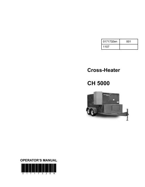
OPERATOR’S MANUAL<br />
0 1 7 1 7 3 2 E N<br />
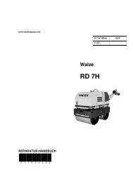
Cross-Heater<br />
<strong>CH</strong> <strong>5000</strong><br />
0171732en 001<br />
1107
<strong>CH</strong> <strong>5000</strong> Table of Contents<br />
1. Foreword 5<br />
2. Safety Information 7<br />
2.1 Operating Safety .................................................................................. 8<br />
2.2 Operator Safety while using Generators .............................................. 9<br />
2.3 Operator Safety while using Combustion Burners ............................. 10<br />
2.4 Maintenance Safety ............................................................................ 10<br />
2.5 Label Locations .................................................................................. 12<br />
2.6 Safety and Operating Labels .............................................................. 13<br />
3. Operation 21<br />
3.1 System Description ............................................................................ 21<br />
3.2 System Component Locations ........................................................... 22<br />
3.3 Control Panel ...................................................................................... 23<br />
3.4 Pre-Season Start-up Preparation ....................................................... 24<br />
3.5 Positioning the Machine ..................................................................... 25<br />
3.6 Preliminary Checks ............................................................................ 26<br />
3.7 Starting the Generator ........................................................................ 27<br />
3.8 Starting the Machine .......................................................................... 28<br />
3.9 Warming the Hoses ............................................................................ 29<br />
3.10 Unwinding and Positioning the Hoses ................................................ 30<br />
3.11 Using the Remote Manifolds .............................................................. 31<br />
3.12 Changing Fuel Sources ...................................................................... 32<br />
3.13 Monitoring the Operating Parameters ................................................ 34<br />
3.14 Clearing a Low Level Fault ................................................................. 35<br />
3.15 Filling the HTF Reservoir .................................................................... 36<br />
3.16 Shutting Down the Machine at End of Day ......................................... 37<br />
3.17 Shutting Down and Restarting the Machine During Operation ........... 38<br />
3.18 Rewinding the Hoses ......................................................................... 39<br />
3.19 Shutting Down the Generator ............................................................. 40<br />
3.20 Activating the RMS Service ................................................................ 41<br />
3.21 Testing the RMS Communications ..................................................... 41<br />
3.22 Operating the RMS 6000 .................................................................... 42<br />
4. Maintenance 43<br />
3
Table of Contents <strong>CH</strong> <strong>5000</strong><br />
4.1 Periodic Maintenance Schedule ..........................................................43<br />
4.2 Installing the NG/LP Burner .................................................................44<br />
4.3 Installing the Diesel Burner .................................................................46<br />
4.4 Setting Up the NG/LP Burner ..............................................................47<br />
4.5 Adjusting the Fuel Pressure ................................................................48<br />
4.6 Adjusting the Burner Air Settings ........................................................50<br />
4.7 Verifying the Burner Combustion ........................................................51<br />
4.8 Changing the Genset Oil and Filter .....................................................53<br />
4.9 Replacing the Genset Fuel Filter .........................................................54<br />
4.10 Cleaning the HTF Strainer Basket .......................................................56<br />
4.11 Storing the Machine ............................................................................58<br />
4.12 List of Abbreviations ............................................................................59<br />
4.13 Troubleshooting ...................................................................................60<br />
4.14 Electrical Schematics ..........................................................................62<br />
5. Technical Data 66<br />
5.1 <strong>CH</strong><strong>5000</strong> Technical Data ......................................................................66<br />
wcghi_bo0171732en_001TOC.fm 4
1. Foreword<br />
wcghi_tx000001gb diesel.fm 5<br />
Foreword<br />
This manual provides information and procedures to safely operate<br />
and maintain this Ground Heaters ® , Inc. model. For your own safety<br />
and protection from injury, carefully read, understand and observe the<br />
safety instructions described in this manual.<br />
Keep this manual or a copy of it with the machine. If you lose this<br />
manual or need an additional copy, please contact Ground Heaters ® ,<br />
Inc. This machine is built with user safety in mind; however, it can<br />
present hazards if improperly operated and serviced. Follow operating<br />
instructions carefully! If you have questions about operating or<br />
servicing this equipment, please contact Ground Heaters ® , Inc.<br />
The information contained in this manual was based on machines in<br />
production at the time of publication. Ground Heaters ® , Inc. reserves<br />
the right to change any portion of this information without notice.<br />
All rights, especially copying and distribution rights, are reserved.<br />
Copyright 2007 by Ground Heaters ® , Inc.<br />
No part of this publication may be reproduced in any form or by any<br />
means, electronic or mechanical, including photocopying, without<br />
express written permission from Ground Heaters ® , Inc.<br />
Any type of reproduction or distribution not authorized by Ground<br />
Heaters ® , Inc. represents an infringement of valid copyrights and will<br />
be prosecuted. We expressly reserve the right to make technical<br />
modifications, even without due notice, which aim at improving our<br />
machines or their safety standards.
wcghi_tx000001gb diesel.fm 6<br />
Foreword
<strong>CH</strong> <strong>5000</strong> Safety Information<br />
2. Safety Information<br />
DANGER<br />
WARNING<br />
CAUTION<br />
This manual contains DANGER, WARNING, CAUTION, NOTICE and<br />
NOTE callouts which must be followed to reduce the possibility of<br />
personal injury, damage to the equipment, or improper service.<br />
This is the safety alert symbol. It is used to alert you to potential<br />
personal injury hazards. Obey all safety messages that follow this<br />
symbol to avoid possible injury or death.<br />
DANGER indicates a hazardous situation which, if not avoided, will<br />
result in death or serious injury.<br />
WARNING indicates a hazardous situation which, if not avoided, could<br />
result in death or serious injury.<br />
CAUTION indicates a hazardous situation which, if not avoided, could<br />
result in minor or moderate injury.<br />
NOTICE: Used without the safety alert symbol, NOTICE indicates a<br />
hazardous situation which, if not avoided, could result in property<br />
damage.<br />
Note: Contains additional information important to a procedure.<br />
wcghi_si000216gb.fm 7
Safety Information <strong>CH</strong> <strong>5000</strong><br />
2.1 Operating Safety<br />
WARNING<br />
Familiarity and proper training are required for the safe operation of<br />
this machine. Machines operated improperly or by untrained personnel<br />
can be dangerous. Read the operating instructions contained in both<br />
this manual and the OEM manuals included with this machine.<br />
Familiarize yourself with the location and proper use of all controls.<br />
Inexperienced operators should receive instruction from someone<br />
familiar with the machine before being allowed to operate it.<br />
NEVER run the machine indoors or in an enclosed area unless<br />
adequate ventilation, through such items as exhaust fans or hoses, is<br />
provided. Exhaust gas from the genset and from the burner contains<br />
carbon monoxide, a deadly poison. Exposure to carbon monoxide<br />
WILL KILL YOU IN MINUTES.<br />
Danger of Electrocution!<br />
Danger of electrocution or severe electrical shock is present<br />
throughout the generator when the engine is running! Read all safety<br />
DANGER<br />
notes contained in this manual before operating or servicing this<br />
equipment.<br />
Only a trained electrician, familiar with this equipment, should attempt<br />
repairs to the generator! Test procedures which require that the<br />
generator be running must be performed using extreme caution.<br />
This machine is built with user safety in mind; however, like any<br />
electrical device it can present serious hazards if improperly operated<br />
and serviced. Follow instructions carefully! Should questions arise<br />
during operation or service of this equipment, contact your local<br />
Ground Heaters dealer.<br />
2.1.1 NEVER start a unit in need of repair.<br />
2.1.2 NEVER transport people in or on the machine.<br />
2.1.3 NEVER run the machine in areas that contain flammable objects,<br />
fuels, or products that produce flammable vapors.<br />
2.1.4 Keep unauthorized personnel, children, and pets away from the<br />
machine.<br />
2.1.5 ALWAYS be sure the machine is on a firm, level surface and will not<br />
tip, roll, slide, or fall while operating.<br />
2.1.6 ALWAYS operate machine with all safety devices and guards in place<br />
and in working order. DO NOT modify or defeat safety devices. DO<br />
NOT operate machine if any safety devices or guards are missing or<br />
inoperative.<br />
2.1.7 ALWAYS refer to the applicable Department of Transportation<br />
regulations before towing.<br />
2.1.8 ALWAYS wear gloves when handling hoses and hot components.<br />
2.1.9 DO NOT smoke while operating the machine.<br />
WARNING<br />
wcghi_si000216gb.fm 8
<strong>CH</strong> <strong>5000</strong> Safety Information<br />
2.2 Operator Safety while using Generators<br />
WARNING<br />
WARNING<br />
WARNING<br />
HIGH VOLTAGE! This unit uses high voltage circuits capable of<br />
causing serious injury or death. Only a qualified electrician should<br />
troubleshoot or repair electrical problems occurring with this<br />
equipment.<br />
Generators present special hazards during operation and servicing.<br />
Read and follow the warning instructions in the genset owner’s<br />
manuals and the safety guidelines below. Failure to follow the<br />
warnings and safety guidelines could result in severe injury or death.<br />
NEVER run the machine indoors or in an enclosed area unless<br />
adequate ventilation, through such items as exhaust fans or hoses, is<br />
provided. Exhaust gas from the genset and from the burner contains<br />
carbon monoxide, a deadly poison. Exposure to carbon monoxide<br />
WILL KILL YOU IN MINUTES.<br />
2.2.1 NEVER operate the generator when open containers of fuel, paint, or<br />
other flammable liquids are near.<br />
2.2.2 Engine antifreeze is toxic to humans and animals. Clean up spills and<br />
dispose of used engine antifreeze in accordance with local<br />
environmental regulations.<br />
2.2.3 NEVER overload the generator. The total amperage of the tools and<br />
equipment attached to the generator must not exceed the load rating<br />
of the generator.<br />
2.2.4 NEVER operate the generator, or tools attached to the generator, with<br />
wet hands.<br />
2.2.5 NEVER allow untrained personnel to operate or service the generator.<br />
The generator set should be set up by a certified electrician.<br />
2.2.6 NEVER touch the hot engine, exhaust, or generator components.<br />
Burns will result.<br />
2.2.1 ALWAYS follow starting and stopping instructions described in this<br />
manual. Know how to operate and stop generator before starting it.<br />
2.2.2 ALWAYS remove jewelry, make sure clothing and shoes are dry, stand<br />
on a dry wooden platform or rubber insulating mat, and use tools with<br />
insulated handles when servicing the machine.<br />
2.2.3 DO NOT start the engine if fuel has spilled or a fuel odor is present.<br />
Move the generator away from the spill and wipe the generator dry<br />
before starting.<br />
2.2.4 DO NOT remove the radiator cap when the engine is running or hot.<br />
The radiator fluid is hot and under pressure and may cause severe<br />
burns!<br />
wcghi_si000216gb.fm 9
Safety Information <strong>CH</strong> <strong>5000</strong><br />
2.2.5 DO NOT pressure wash the control panel, generator end, or any other<br />
electrical components when cleaning the unit. Never allow water to<br />
accumulate around the base of the generator set. If water is present,<br />
DO NOT service!<br />
2.3 Operator Safety while using Combustion Burners<br />
WARNING<br />
WARNING<br />
Combustion burners present special hazards during operation and<br />
fueling. Read and follow the warning instructions in the burner owner’s<br />
manual and the safety guidelines below. Failure to follow the warnings<br />
and safety guidelines could result in severe injury or death.<br />
NEVER run the machine indoors or in an enclosed area unless<br />
adequate ventilation, through such items as exhaust fans or hoses, is<br />
provided. Exhaust gas from the genset and from the burner contains<br />
carbon monoxide, a deadly poison. Exposure to carbon monoxide<br />
WILL KILL YOU IN MINUTES.<br />
2.3.1 ALWAYS refill the fuel tank in a well-ventilated area.<br />
2.3.2 ALWAYS replace the fuel tank cap after refueling.<br />
2.3.3 DO NOT fill or drain the fuel tank near an open flame, while smoking,<br />
or while the engine is running.<br />
2.3.4 DO NOT spill fuel when refueling the machine. Clean up spilled fuel<br />
immediately.<br />
2.3.5 DO NOT touch or lean against hot exhaust pipes.<br />
2.3.6 DO NOT refuel a hot or running machine.<br />
2.4 Maintenance Safety<br />
WARNING<br />
HIGH VOLTAGE! This unit uses high voltage circuits capable of<br />
causing serious injury or death. Only a qualified electrician should<br />
troubleshoot or repair electrical problems occurring with this<br />
equipment.<br />
2.4.1 DO NOT use gasoline or other types of fuels or flammable solvents to<br />
clean parts, especially in enclosed areas. Fumes from fuels and<br />
solvents can become explosive.<br />
2.4.2 ALWAYS disconnect the negative (-) battery cable before servicing the<br />
machine.<br />
2.4.3 ALWAYS replace the safety devices and guards after repairs and<br />
maintenance.<br />
2.4.4 ALWAYS keep the machine clean and labels legible. Replace all<br />
missing and hard-to-read labels. Labels provide important operating<br />
instructions and warn of dangers and hazards.<br />
wcghi_si000216gb.fm 10
<strong>CH</strong> <strong>5000</strong> Safety Information<br />
2.4.5 ALWAYS make sure slings, chains, hooks, ramps, jacks and other<br />
types of lifting devices are attached securely and have enough weightbearing<br />
capacity to lift or hold the machine safely. Always remain<br />
aware of the location of other people in the area when lifting the<br />
machine.<br />
2.4.6 ALWAYS replace or repair electrical components with components<br />
that are identical in rating and performance as the original component.<br />
2.4.7 ALWAYS check the tires on the trailer for tread wear, inflation, and<br />
condition. Replace worn tires.<br />
2.4.8 ALWAYS connect the safety chains.<br />
2.4.9 ALWAYS make sure directional and trailer lights are connected and<br />
working properly.<br />
2.4.10 ALWAYS check that the lug nuts holding the wheels are tight and that<br />
none are missing.<br />
2.4.11 DO NOT attempt tire repairs. Always have a qualified tire dealer or<br />
repair service perform tire repairs.<br />
wcghi_si000216gb.fm 11
Safety Information <strong>CH</strong> <strong>5000</strong><br />
2.5 Label Locations<br />
1<br />
3<br />
14<br />
6<br />
9<br />
13<br />
13<br />
10 21<br />
15<br />
21<br />
wcghi_si000216gb.fm 12<br />
4<br />
18<br />
5<br />
19<br />
6<br />
28<br />
3<br />
23<br />
16<br />
13<br />
2<br />
20<br />
12<br />
7<br />
ghi_gr004615<br />
13<br />
17<br />
11<br />
8
<strong>CH</strong> <strong>5000</strong> Safety Information<br />
2.6 Safety and Operating Labels<br />
Ref. Label Meaning<br />
1 Warning: Electrical shock hazard!<br />
Refer to the Operator’s Manual.<br />
2 Warning: Hot surface hazard!<br />
WARNING<br />
Strainer is hot.<br />
Refer to the Operator’s Manual.<br />
WARNUNG<br />
ADVERTENCIA<br />
AVERTISSEMENT<br />
3 Warning: Hot surface hazard.<br />
WARNING<br />
Wear safety gloves.<br />
WARNUNG<br />
Wear eye protection.<br />
ADVERTENCIA<br />
AVERTISSEMENT<br />
173199<br />
4 Warning:<br />
WARNING<br />
Read and understand the supplied<br />
Operator’s Manual before operating this<br />
machine. Failure to do so increases the risk<br />
READ AND UNDERST AND THE SUPPLIED OPERA TOR’S MANUAL BEFORE<br />
OPERATING THIS MA<strong>CH</strong>INE . FAILURE TO DO SO INCREASES THE<br />
of injury to yourself and others.<br />
RISK OF INJURY TO OURSELF Y OR OTHERS.<br />
WARNUNG<br />
VOR INBETRIEBNAHME DIESES GREÄTES BEIGEFÜG TE BETRIEB SVOR-<br />
S<strong>CH</strong>RIFT LESEN UND VERSTEHEN. NI<strong>CH</strong>TBEFOLGUNG ERHÖHT AS D<br />
RISIKO ZU EIGENER VERLETZUNG ODER ANDERER.<br />
ADVERTENCIA<br />
LEA Y ENTIENDA EL MANUAL DE OPERACION PRO VISTO CON EL<br />
EQUIPO ANTES DE QUE OPERE ESTE . EQUIPO DE NO HACERSE<br />
ASI. PODRIA AUMENTAR EL RIESGO DE AÑOS D PERSONALES Y<br />
A OTRAS PERSONAS.<br />
AVERTISSEMENT<br />
LIRE ET COMPRENDRE LA NOTICE OI D’EMPL FOURNIE VEC A LA<br />
MA<strong>CH</strong>INE AVANT DE LA MET TRE EN SERVICE . A DEFAUT. VOUS<br />
AUGMENTERIEZ LE RISQUE DE VOUS EXPOSER UTRES ET LES A<br />
A DES BLES SURES.<br />
wcghi_si000216gb.fm 13<br />
172634<br />
173221
Safety Information <strong>CH</strong> <strong>5000</strong><br />
Ref. Label Meaning<br />
5 Danger: Exhaust gas is deadly!<br />
DANGER<br />
Do not operate machine indoors. Refer to<br />
GEFAHR<br />
the Operator’s Manual.<br />
PELIGRO<br />
DANGER<br />
EXHAUST GAS IS DEADLY.<br />
DO NOT OPERATE MA<strong>CH</strong>INE INDOORS.<br />
REFER TO OPERATORíS MANUAL.<br />
ABGAS IST T÷DLI<strong>CH</strong> .<br />
MAS<strong>CH</strong>INE NUR IM FREIEN BETREIBEN.<br />
SIEHE BETRIEBSANLEITUNG.<br />
EL GAS DE ESCAPE ES MORTAL .<br />
NO OPERE LA M¡QUINA EN I NTERIORES.<br />
CONSULTE EL MANUAL DE OPERACI”N.<br />
LES GAZ D'…<strong>CH</strong>APPEMENT SONT MORTELS.<br />
NE PAS UTILISER LA MA<strong>CH</strong>INE ¿ L'INT…RIEUR .<br />
SE REPORTER ¿ LA NOTICE D'EMPLOI.<br />
6 Warning: Hand entanglement hazard!<br />
WARNING<br />
Moving parts can crush and cut. Do not<br />
operate with guard removed.<br />
WARNUNG<br />
ADVERTENCIA<br />
AVERTISSEMENT<br />
7 Warning: Fire and explosion hazard!<br />
WARNING<br />
WARNUNG<br />
G20<br />
ADVERTENCIA<br />
AVERTISSEMENT<br />
WARNING<br />
WARNUNG<br />
G31<br />
ADVERTENCIA<br />
AVERTISSEMENT<br />
wcghi_si000216gb.fm 14<br />
173224<br />
173222<br />
172626<br />
When using G20 (Natural Gas), position<br />
the fuel selection valve in the open<br />
position.<br />
Warning: Fire and explosion hazard!<br />
When using G31 (Propane), position the<br />
fuel selection valve in the closed position.
<strong>CH</strong> <strong>5000</strong> Safety Information<br />
Ref. Label Meaning<br />
8<br />
WARNING<br />
WARNUNG<br />
ADVERTENCIA<br />
AVERTISSEMENT<br />
LICENSED GAS TE<strong>CH</strong>NICIAN REQUIRED.<br />
NATURAL GAS/LIQUID PROPANE BURNER SETUP AND INSTALLATION, F UEL SUPPLY<br />
CONNECTION, TEST FIRING AND BURNER ADJUSTMENT MUST BE PERFORMED B Y A<br />
LICENSED PROFESSIONAL GAS TE<strong>CH</strong>NICIAN AND MUST CONFORM TO THE REQUIREMENTS<br />
OF ALL RELEVANT LOCAL, STATE, PROVINCIAL AND FEDERAL AUTHORITIES.<br />
FAILURE TO HEED THIS WARNING MAY RESULT IN AN EXPLOSION AND/OR FIRE CAUSING<br />
PROPERTY DAMAGE, PERSONAL INJURY OR DEATH.<br />
ZUGELASSENER GASTE<strong>CH</strong>NIKER ERFORDERLI<strong>CH</strong>.<br />
DIE EINRI<strong>CH</strong>UNG UND INSTALLATION DES ERDGAS/FL‹S SIGPROPANGAS-BRENNERS, DES<br />
KRAFTSTOFFVERSORGUNGSANS<strong>CH</strong>LUSSES, DER TESTZ‹NDUNG UND<br />
BRENNEREINSTELLUNG MUSS VON EINEM AUSGEBILDETEN UND ZUGELASSENEN<br />
GASTE<strong>CH</strong>NIKER VORGENOMMEN WERDEN UND MUSS DEN ANFORDERUNGEN ALLER<br />
GELTENDEN VORS<strong>CH</strong>RIFTEN AUF LOKALER, LANDES- UND BUNDESEBENE ENTSPRE<strong>CH</strong>EN.<br />
DIE NI<strong>CH</strong>TBEA<strong>CH</strong>TUNG DIESER WARNUNG KANN ZU EXPLOSION UND/ODER BRAND F‹HREN<br />
UND SA<strong>CH</strong>S<strong>CH</strong>ADEN, VERLETZUNGEN ODER TOD VERURSA<strong>CH</strong>EN.<br />
SE REQUIERE UN T…CNICO GASISTA AUTORIZADO.<br />
EL MONTAJE Y LA INSTALACI”N DEL QUEMADOR DE PROP ANO LÕQUIDO/GAS NATURAL, LA<br />
CONEXI”N DEL SUMINISTRO DE COMBUSTIBLE , EL DISPARO EXPERIMENTAL Y EL AJUSTE<br />
DEL QUEMADOR DEBEN SER REALIZADOS POR UN T…CNICO GASISTA PROFESIONAL<br />
AUTORIZADO Y DEBEN CUMPLIR CON LOS REQUISITOS DE TODAS LAS AUTORIDADES<br />
RELEVANTES LOCALES, ESTATALES, PROVINCIALES Y FEDERALES.<br />
EN CASO DE NO CUMPLIR ESTA ADVERTENCIA PODRÕA PROVOCARSE UNA EXPLOSI”N O UN<br />
INCENDIO QUE CAUSAR¡ D A—OS MATERIALES, LESIONES PERSONALES O LA MUERTE.<br />
TE<strong>CH</strong>NICIEN QUALIFI…, SP…CIALISTE DU GAZ INDISPENSABLE.<br />
L'INSTALLATION DE BR¤LEURS DE GAZ NATUREL/PROPANE LIQUIDE, LE RACCORDEMENT<br />
DE L'ARRIV…E DE CARBURANT, L'ALLUMAGE D'ESSAI ET L'AJUSTEMENT DES BR¤LEURS<br />
DOIVENT TRE CONFI…S ¿ UN TE<strong>CH</strong>NICIEN PROFESSIONNEL QUALIFI…, SP…CIALISTE DU<br />
GAZ ET EFFECTU…S CONFORM…MENT AUX EXIGENCES DE TOUTES LES INSTANCES<br />
LOCALES, R…GIONALES, PROVINCIALES ET NATIONALES.<br />
RESPECTER CET AVERTISSEMENT SOUS PEINE D'EXPLOSION ET/OU D'INCENDIE CAUSANT<br />
DES D…G¬TS MAT…RIELS ET DES BLESSURES, …VENTUELLEMENT MORTELLES.<br />
173216<br />
Warning: Fire hazard!<br />
Natural gas/liquid propane burner setup and installation, fuel supply connection,<br />
test firing, and burner adjustment must be performed by a licensed, professional<br />
gas technician and must conform to the requirements of all relevant local, state,<br />
provincial, and federal authorities.<br />
Failure to heed this warning may result in an explosion and/or fire causing<br />
property damage, personal injury, or death.<br />
9 Warning:<br />
WARNING<br />
Do not engage trailer jack while<br />
WARNUNG<br />
transporting the machine.<br />
ADVERTENCIA<br />
Refer to the Operator’s Manual for further<br />
AVERTISSEMENT<br />
instructions on transporting the machine.<br />
173200<br />
wcghi_si000216gb.fm 15
Safety Information <strong>CH</strong> <strong>5000</strong><br />
Ref. Label Meaning<br />
10 Caution: Lift point.<br />
CAUTION<br />
Attach lifting device in this location.<br />
VORSI<strong>CH</strong>T<br />
PRECAUCION<br />
PRECAUTION<br />
11 Caution: Only diesel fuel may be used in<br />
this machine.<br />
! CAUTION<br />
! VORSI<strong>CH</strong>T<br />
D ! PRECAUCION<br />
DIESEL ! PRECAUCION<br />
12 Low level cutoff device label:<br />
Refer to Operator’s Manual. See section<br />
Clearing a Low Level Fault.<br />
13 Tie down location label:<br />
This label indicates areas on the machine<br />
that may be used for securing the machine<br />
during transport or storage.<br />
173202<br />
wcghi_si000216gb.fm 16<br />
173201
<strong>CH</strong> <strong>5000</strong> Safety Information<br />
Ref. Label Meaning<br />
14 Hose reel brake label:<br />
This label indicates information regarding<br />
the operation of the hose reel brake<br />
assembly.<br />
15 Lifting point range label:<br />
This label indicates the range of lifting<br />
points (between the center of gravity<br />
labels).<br />
173204<br />
16 Weight/mass label:<br />
This label indicates the total weight of the<br />
LBS<br />
KG<br />
11750<br />
5350 173217<br />
wcghi_si000216gb.fm 17<br />
machine, including the trailer and a full fuel<br />
tank.<br />
17 Diesel fuel blend guide:<br />
This label gives diesel fuel blending<br />
requirements. Refer to the Operator’s<br />
Manual for more information.<br />
5 < < 25 ( / 15 ) ( / -4 )<br />
25<br />
Safety Information <strong>CH</strong> <strong>5000</strong><br />
Ref. Label Meaning<br />
18<br />
19<br />
NATURAL GAS (NG) BURNER<br />
FIRING RATE/TAUX <strong>CH</strong>AUFFE<br />
550 CFH<br />
CAPACITY/CAPACIT… BTUH / KW<br />
550,000 / 161.2<br />
BURNER MODEL/BRULEUER MODELE<br />
BECKETT CG 10.3 S<br />
ELECTRICAL RATING/LA TAUX ELECTRIQUE 120/240 VAC / 60 Hz / SINGLE PHASE / LES S THAN 50 AMP<br />
MIN CIRCUIT AMP ACITY/AMPERES DU CIRCUIT DU MIN<br />
1 x 15A / 1 x 50A<br />
GAS SUPPLY PRESSURE/PRESSION D’ORIFICE DE GAZ<br />
3.5" TO 9" W.C.<br />
MANIFOLD GAS PRES SURE/PRESSION DE GAZ DIVERSE<br />
2.1" W.C.<br />
GAS MANIFOLD ORIFICE<br />
1.265"<br />
LIQUID PROPANE VAPOR (LP) BURNER<br />
FIRING RATE/TAUX <strong>CH</strong>AUFFE<br />
220 CFH<br />
CAPACITY/CAPACIT… BTUH / KW<br />
550,000 / 161.2<br />
BURNER MODEL/BRULEUER MODELE<br />
BECKETT CG 10.3 S<br />
ELECTRICAL RATING/LA TAUX ELECTRIQUE 120/240 VAC / 60 Hz / SINGLE PHASE / LES S THAN 50 AMP<br />
MIN CIRCUIT AMP ACITY/AMPERES DU CIRCUIT DU MIN<br />
1 x 15A / 1 x 50A<br />
GAS SUPPLY PRESSURE/PRESSION D’ORIFICE DE GAZ<br />
3.5" TO 9" W.C.<br />
MANIFOLD GAS PRES SURE/PRESSION DE GAZ DIVERSE<br />
2.1" W.C.<br />
GAS MANIFOLD ORIFICE<br />
.437"<br />
DIESEL / OIL BURNER<br />
FIRING RATE/TAUX <strong>CH</strong>AUFFE<br />
4.0 US GPH<br />
NOZZLE SIZE/TYPE CICLEUR<br />
4.0 GPH 80 B<br />
CAPACITY/CAPACIT… BTUH / KW<br />
550,000 / 161.2<br />
BURNER MODEL/BRULEUER MODELE<br />
BECKETT GH203<br />
ELECTRICAL RATING/LA TAUX ELECTRIQUE 120/240 VAC / 60 Hz / SINGLE PHASE / LES S THAN 50 AMP<br />
MIN CIRCUIT AMP ACITY/AMPERES DU CIRCUIT DU MIN<br />
1 x 15A / 1 x 50A<br />
FUEL NOT HEAVIER THAN NO. 2 FUEL OIL/COMBUSTIBLE PAS PLUS LOURD QUE DE L’HUILE A FOURNAISE NO. 2<br />
Ground Heaters, Inc.<br />
1271 Judson Road<br />
Spring Lake, Michigan 49456<br />
<strong>CH</strong><strong>5000</strong><br />
HEATER RATING PLATE<br />
Æ<br />
C US<br />
Heater rating label:<br />
This label displays important technical information relating to the setup and<br />
operation of the machine.<br />
172632<br />
wcghi_si000216gb.fm 18<br />
CSA B140.7 UL 726<br />
CSA B140.0 UL 795<br />
ANSI Z21.13∑CSA 4.9 LOW PRESS. BOILER<br />
173225<br />
Start pump:<br />
The label indicates that to start the pump<br />
on the machine, the pressure valve must<br />
be in the open position.<br />
Run machine:<br />
To run the machine, the pressure valve<br />
must be in the closed position.
<strong>CH</strong> <strong>5000</strong> Safety Information<br />
Ref. Label Meaning<br />
20 HTF fill instructions:<br />
wcghi_si000216gb.fm 19<br />
In normal operation mode, the fill valve<br />
must be in the closed position<br />
and the coolant control valve<br />
must be in the open position.<br />
In HTF fill mode, the fill valve must be<br />
in the open position<br />
and the coolant control valve<br />
must be in the closed position.<br />
21 Center of gravity.<br />
22 Hand entanglement hazard!<br />
Moving parts can crush and cut. Do not<br />
operate with guard removed.<br />
23 Hot surface hazard!<br />
24 Electric shock hazard!<br />
172624
Safety Information <strong>CH</strong> <strong>5000</strong><br />
Ref. Label Meaning<br />
25 Wear safety gloves!<br />
26 Wear eye protection!<br />
27 Consult Operator’s Manual!<br />
28 Temperature indication label:<br />
THERMAX This label indicates the temperature of the<br />
flue box. The black circles represent the<br />
temperature of the flue box at that location.<br />
The maximum recommended temperature<br />
of the flue box is 149°C (300°F).<br />
fi<br />
132”C 138”C<br />
4 LEVEL STRIP<br />
143”C 149”C<br />
270”F<br />
280”F 290”F<br />
CENTERS TURN BLACK AT RATING SHOWN<br />
300”F<br />
wcghi_si000216gb.fm 20
<strong>CH</strong> <strong>5000</strong> Operation<br />
3. Operation<br />
3.1 System Description<br />
The Cross Heater <strong>5000</strong> is a versatile hydronic heating system that<br />
uses advanced technology to thaw frozen ground, cure concrete,<br />
prevent frost, and heat or dry multiple types of work spaces. The Cross<br />
Heater hydronic heating system consists of:<br />
• Trailer-mounted heater/burner assembly<br />
• Self-contained pump system<br />
• Removable remote manifold that allows for maximum Heat<br />
Transfer Fluid flow at long distances<br />
• Optional robust 12kW genset that powers external Hose<br />
Handling Systems or Heat Xchangers<br />
The Cross Heater <strong>5000</strong> system heats the heat transfer fluid (HTF),<br />
which is continuously circulated through a vented, closed loop system.<br />
The vented, closed loop system includes a hose system which carries<br />
the heated HTF through the machine, thereby radiating and<br />
transferring the heat to the required application area.<br />
wcghi_tx000732gb.fm 21
Operation <strong>CH</strong> <strong>5000</strong><br />
3.2 System Component Locations<br />
Ref. Description Ref. Description<br />
1 Hose reel 6 Trailer jack<br />
2 Hose connection manifold 7 HTF pump and motor<br />
3 HTF fill access panels 8 Fuel tank fill access panel<br />
4 Burner exhaust 9 Lifting point<br />
5 Generator 10 Strobe light<br />
wcghi_tx000732gb.fm 22<br />
1<br />
5<br />
2<br />
10<br />
6<br />
7<br />
9<br />
3<br />
wcghi_gr004101<br />
4<br />
8
<strong>CH</strong> <strong>5000</strong> Operation<br />
3.3 Control Panel<br />
b<br />
c<br />
d<br />
e<br />
f<br />
Ref. Instrument/switch Function<br />
a Start button Connects power to the machine<br />
controls.<br />
b Ground fault interrupter (GFI) Electrical safety mechanism that<br />
protects the operator from injury.<br />
c Low level fault indicator light Signifies low level fault when lit.<br />
d Burner fault indicator light Signifies burner fault when lit.<br />
e HTF fill switch Overrides the low level cutoff device to<br />
operate pump during HTF filling.<br />
f Pump ON-OFF switch Switches power to the pump.<br />
g Light ON-OFF switch Switches power to the light.<br />
h Burner ON-OFF switch Switches power to the burner.<br />
i Main temperature controller Sets desired temperature of HTF.<br />
j Hour meter Meters usage of <strong>CH</strong> <strong>5000</strong>.<br />
k Stop button Disconnects power to the machine<br />
controls.<br />
wcghi_tx000732gb.fm 23<br />
TM<br />
j<br />
a<br />
k<br />
i<br />
h<br />
g<br />
wcghi_gr004107
Operation <strong>CH</strong> <strong>5000</strong><br />
3.4 Pre-Season Start-up Preparation<br />
Before each seasonal use, the machine must be prepared for<br />
operation. Perform the following tasks after taking the machine out of<br />
storage:<br />
• Remove all plastic wrap or other waterproof material from the<br />
chimney and burner.<br />
• Remove all carbon buildup from the heater and burner<br />
assemblies.<br />
• Replace the burner nozzle.<br />
• Replace the fuel filter element.<br />
• Verify electrode position.<br />
• Verify fuel pump pressure.<br />
• Verify burner combustion quality. See section Burner<br />
Adjustments.<br />
• Verify correct operation of the low level shutdown device.<br />
• Verify correct operation of the temperature control device.<br />
• Clean the HTF strainer basket. See section Cleaning the HTF<br />
Strainer Basket.<br />
wcghi_tx000732gb.fm 24
<strong>CH</strong> <strong>5000</strong> Operation<br />
3.5 Positioning the Machine<br />
1<br />
2<br />
3<br />
4<br />
Normal positioning and setup is as follows:<br />
3.5.1 Position the <strong>CH</strong> <strong>5000</strong> trailer close to the application area.<br />
3.5.2 Chock the wheels to prevent accidental rolling.<br />
3.5.3 Level the trailer using the trailer jack.<br />
3.5.4 Place the machine on solid, stable ground to prevent rollovers.<br />
Note: The <strong>CH</strong> <strong>5000</strong> machine may be air lifted to the top of a structure<br />
for operation if necessary. Use the lifting point to do so.<br />
wcghi_tx000732gb.fm 25<br />
wcghi_gr004096
Operation <strong>CH</strong> <strong>5000</strong><br />
3.6 Preliminary Checks<br />
Before starting the machine, check the following:<br />
• Location—see section Positioning the Machine.<br />
• Fuel supply—verify the tank is filled with the correct type of fuel.<br />
• Generator—check the following:<br />
- Oil level<br />
- Coolant level<br />
- Exhaust system integrity<br />
- Fuel system integrity<br />
- Electrical system integrity<br />
- Mechanical system integrity<br />
• Heat transfer fluid level—verify the reservoir is full.<br />
• Circuit breaker and control switches—all must be in the OFF<br />
position.<br />
• Hose connections—verify all fuel and heat transfer hose<br />
connections are secured.<br />
wcghi_tx000732gb.fm 26
<strong>CH</strong> <strong>5000</strong> Operation<br />
3.7 Starting the Generator<br />
3.7.1 Perform the preliminary checks on the machine. See section<br />
Preliminary Checks.<br />
3.7.2 Move the circuit breakers on the genset control panel to the OFF<br />
position.<br />
3.7.3 Prime the fuel system if:<br />
• Fuel has been replenished<br />
• Fuel filter has been changed<br />
Note: If these conditions have not<br />
been met, the fuel system does NOT<br />
need to be primed.<br />
3.7.4<br />
To prime the fuel system, hold the<br />
control switch to the STOP/PRIME<br />
position for at least one minute.<br />
Note: The priming sequence will<br />
begin after two seconds.<br />
Push and hold the control switch to<br />
the START position until the genset<br />
starts. The status indicator light on<br />
the control switch will flash during the<br />
preheat and crank sequences. The<br />
indicator light will illuminate solid<br />
when the starter disconnects,<br />
indicating a successful start.<br />
Note: In colder temperatures, the<br />
preheat sequence can last up to 15<br />
seconds.<br />
NOTICE: DO NOT crank the starter<br />
for more than 30 seconds at a time<br />
and wait at least two minutes before<br />
trying again. Excessive cranking can<br />
overheat and damage the starter.<br />
3.7.5 In cold weather, allow the genset to warm up for at least two minutes<br />
before operating the machine.<br />
3.7.6 Move the circuit breakers on the genset control panel to the ON<br />
position.<br />
wcghi_tx000732gb.fm 27<br />
START<br />
STOP<br />
START<br />
STOP
Operation <strong>CH</strong> <strong>5000</strong><br />
3.8 Starting the Machine<br />
3.8.1 Perform the necessary preliminary checks. See section Preliminary<br />
Checks.<br />
3.8.2 Start the generator. See section Starting the Generator.<br />
3.8.3 Press the Start Button.<br />
3.8.4 Warm the hoses. See section Warming the Hoses.<br />
3.8.5 Initiate the HTF flow:<br />
• Verify the pressure valve is in the OPEN position.<br />
• Turn the pump switch to the ON position.<br />
• Verify the pressure is rising by monitoring the pump pressure<br />
gauge.<br />
3.8.6 Unwind and position the hoses in the application area. See section<br />
Unwinding and Positioning the Hoses.<br />
3.8.7 Specify the set value (SV) on the<br />
temperature controller to the desired<br />
application temperature.<br />
3.8.8 Move the pressure valve to the CLOSED<br />
3.8.9<br />
position.<br />
Continue with normal operating<br />
## C<br />
PV<br />
procedures.<br />
## C SV<br />
wcghi_tx000732gb.fm 28<br />
omron E5CN<br />
wcghi_gr004070
<strong>CH</strong> <strong>5000</strong> Operation<br />
3.9 Warming the Hoses<br />
3.9.1<br />
NOTICE: The machine is equipped with a variable frequency drive<br />
(VFD) which requires a minimum temperature of -9°C (15°F) to<br />
operate properly. The VFD is equipped with an automatic heater that<br />
initiates when the start button is pressed. The pump motor will not<br />
engage until the VFD has reached -9°C (15°F). This process can take<br />
up to 30 minutes at -40°C (-40°F).<br />
After starting the generator and pressing the start button, carry out the<br />
following procedure to warm the hoses.<br />
Use the up and down arrows on the<br />
temperature controller to make the set value<br />
(SV) 21°C (70°F).<br />
Note: The actual temperature of the HTF<br />
(PV) is displayed in red.<br />
## C<br />
PV<br />
3.9.2 Move the burner switch to the ON (|) position.<br />
Verify the following sequence occurs:<br />
• After a 5-second delay, the burner motor<br />
starts.<br />
• After another 15-second delay, the<br />
burner fires.<br />
• The burner is operating with no visible<br />
exhaust smoke.<br />
Note: If the burner is not operating properly,<br />
contact your local Ground Heaters, Inc. distributor.<br />
wcghi_tx000732gb.fm 29<br />
## C<br />
SV<br />
omron E5CN<br />
wcghi_gr004070<br />
wcghi_gr004071
Operation <strong>CH</strong> <strong>5000</strong><br />
3.10 Unwinding and Positioning the Hoses<br />
See Graphic ghi_gr004631<br />
To unwind and position the hoses, carry out the following procedure.<br />
3.10.1 Turn the hose reel brake T-handle counter-clockwise to release the<br />
brake.<br />
3.10.2 Connect loop 1 to the male hose connection manifold (a).<br />
3.10.3 Move the pump switch to the OFF position. Allow the pressure to drop<br />
to 0 kg/cm 2 (0 psi).<br />
3.10.4 Pull the hose loop off the hose reel and position the hose within the<br />
application area.<br />
3.10.5 Stop pulling the hose when the connection between loop 1and loop 2<br />
is exposed.<br />
NOTICE: Do NOT over-spin the hose reel near the end of hose loop 2.<br />
Failure to comply will damage the machine.<br />
3.10.6 Disconnect loop 1 from loop 2 at the quick connect coupling.<br />
3.10.7 Connect loop 1 male coupling to the return female hose connection<br />
manifold.<br />
3.10.8 Connect loop 2 male coupling to the female hose connection manifold.<br />
3.10.9 Connect loop 2 female coupling to male hose connection manifold.<br />
3.10.10 Position hose loop 2 within the application area.<br />
3.10.11 Turn the hose reel brake T-handle clockwise to lock the hose reel.<br />
3.10.12 Repeat the preceding steps for the remaining hose reel.<br />
3.10.13 Move pump switch to the ON position.<br />
3.10.14 Continue with normal operating procedures.<br />
wcghi_tx000732gb.fm 30<br />
a<br />
ghi_gr004631
<strong>CH</strong> <strong>5000</strong> Operation<br />
3.11 Using the Remote Manifolds<br />
See Graphic ghi_gr004630<br />
In order to use the remote manifolds, you need two additional leader<br />
hoses from Ground Heaters, Inc.<br />
3.11.1 Turn the hose reel brake T-handle counter-clockwise to release the<br />
brake.<br />
3.11.2 Move the pump switch to the OFF position. Allow the pressure to drop<br />
to 0 kg/cm 2 (0 psi).<br />
3.11.3 Remove the remote manifolds (a) from the machine and place them in<br />
the application area.<br />
• Place the manifolds no more than 50 feet from the machine to<br />
allow the leader hoses to be connected.<br />
3.11.4 Pull both loops off the hose reel and disconnect at the middle coupling.<br />
3.11.5 Connect one leader hose (b) to the male connection manifold.<br />
3.11.6 Connect the remaining leader hose to the female connection manifold.<br />
3.11.7 Connect the remaining leader hose ends to the supply and return<br />
fittings on the ends of the remote manifolds.<br />
3.11.8 Connect each end of the hose loops to the remote manifolds.<br />
3.11.9 Repeat the preceding steps for the remaining hose reel.<br />
3.11.10 Position the hose loops in the application area.<br />
3.11.11 Continue with normal operating procedures.<br />
wcghi_tx000732gb.fm 31<br />
b<br />
a<br />
ghi_gr004630<br />
a<br />
b
Operation <strong>CH</strong> <strong>5000</strong><br />
3.12 Changing Fuel Sources<br />
WARNING<br />
Extreme fire and explosion hazard! Only a licensed, professional gas<br />
technician should attempt installation, fuel supply connection, setup,<br />
adjustment, and testing of the burner. All connections and settings<br />
must conform to relevant local, state, provincial, and federal<br />
requirements.<br />
The machine runs on three types of fuel; natural gas (NG), liquid<br />
propane (LP), and diesel fuel. Before operation, verify the correct type<br />
of burner is installed and that the burner has been properly setup and<br />
tested.<br />
• For NG and LP, the NG/LP burner must be installed. See section<br />
Installing the NG/LP Burner.<br />
• For diesel fuel, the diesel burner must be installed. See section<br />
Installing the Diesel Burner.<br />
To change from NG or LP to diesel fuel, carry out the following<br />
procedure:<br />
3.12.1 Remove the NG/LP burner.<br />
3.12.2 Install the diesel burner. See section Installing the Diesel Burner.<br />
3.12.3 Adjust the fuel pressure if necessary. See section Adjusting the Fuel<br />
Pressure.<br />
3.12.4 Adjust the burner air settings. See section Adjusting the Burner Air<br />
Settings.<br />
3.12.5 Verify the burner combustion values. See section Verifying the Burner<br />
Combustion.<br />
To change from diesel fuel to NG/LP, carry out the following<br />
procedure:<br />
3.12.6 Remove the diesel burner.<br />
3.12.7 Install the NG/LP burner. See section Installing the NG/LP Burner.<br />
3.12.8 Adjust the fuel pressure if necessary. See section Adjusting the Fuel<br />
Pressure.<br />
3.12.9 Adjust the burner air setttings. See section Adjusting the Burner Air<br />
Settings.<br />
3.12.10 Verify the burner combustion values. See section Verifying the Burner<br />
Combustion.<br />
wcghi_tx000732gb.fm 32
<strong>CH</strong> <strong>5000</strong> Operation<br />
To change from NG to LP or vice-versa, carry out the following<br />
procedure:<br />
3.12.11 Verify that the machine is shut down and all power is disabled.<br />
3.12.12 Move the fuel selection valve (a) to the appropriate position:<br />
• NG - Move the fuel selection valve to the OPEN position<br />
• LP - Move the fuel selection valve to the CLOSED position.<br />
3.12.13 Adjust the fuel pressure if necessary. See section Adjusting the Fuel<br />
Pressure.<br />
3.12.14 Adjust the burner air settings if necessary. See section Adjusting the<br />
Burner Air Settings.<br />
3.12.15 Verify the burner combustion values. See section Verifying the Burner<br />
Combustion.<br />
wcghi_tx000732gb.fm 33<br />
a<br />
LP NG<br />
ghi_gr004628
Operation <strong>CH</strong> <strong>5000</strong><br />
3.13 Monitoring the Operating Parameters<br />
The following parameters should be monitored every 8–24 hours:<br />
• Fuel level<br />
Keep track of fuel consumption to plan a needed filling schedule.<br />
• Flue box temperature<br />
Check the temperature indication labels often; if the temperature<br />
rises above 149°C (300°F), shut down the machine and inspect<br />
the flue box.<br />
• HTF level<br />
• HTF supply pressure<br />
• Leaks<br />
Keep a watchful eye on all hoses, fittings, and connections.<br />
• Strobe light—The strobe (performance monitoring light) flashes<br />
when all systems are functioning properly. The strobe will go out<br />
when there is a power failure or a burner fault.<br />
• HTF return temperature— Consult your site engineer for the<br />
proper HTF return temperatures OR contact Ground Heaters,<br />
Inc. for application support.<br />
Note: The proper temperatures for all applications are based on tests<br />
conducted at Ground Heaters, Inc. ® Your application temperatures<br />
may vary depending on environmental conditions at the work site.<br />
wcghi_tx000732gb.fm 34
<strong>CH</strong> <strong>5000</strong> Operation<br />
3.14 Clearing a Low Level Fault<br />
To clear a low level fault condition, carry out the following procedure:<br />
3.14.1 Move the burner switch to the OFF position.<br />
3.14.2 Move the pump switch(es) to the OFF position.<br />
3.14.3 Locate and repair the source of the low level fault.<br />
3.14.4 Fill the HTF to the minimum indicator mark. See section Filling the HTF<br />
Reservoir.<br />
3.14.5 Press the manual reset button (a).<br />
3.14.6 After the burner ignites, move the pump switch(es) to the ON position<br />
(one at a time).<br />
3.14.7 Continue with normal operational procedures.<br />
wcghi_tx000732gb.fm 35<br />
a<br />
ghi_gr004666
Operation <strong>CH</strong> <strong>5000</strong><br />
3.15 Filling the HTF Reservoir<br />
See graphic: ghi_gr004667<br />
To fill the HTF reservoir, carry out the following procedure.<br />
Setting up:<br />
3.15.1 Verify that the machine is operational.<br />
3.15.2 Move the burner switch to the OFF position.<br />
3.15.3 Move the pump switch(es) to the OFF position.<br />
3.15.4 Allow the machine to cool 10 minutes or more.<br />
3.15.5 Remove and clean the HTF fill hose.<br />
3.15.6 Place the hanging end of the fill hose into a container of HTF.<br />
3.15.7 Move the coolant control valve (c) to the CLOSED position.<br />
3.15.8 Move the fill valve (b) to the OPEN position.<br />
Filling:<br />
3.15.9 Move the HTF fill switch to the ON position.<br />
Note: The pump will operate at 1/3 speed.<br />
3.15.10 Observe the sight gauge on the HTF reservoir.<br />
3.15.11 Move the HTF fill switch to the OFF position when the reservoir is filled<br />
to the minimum indicator mark.<br />
Preparing for operation:<br />
3.15.12 Move the coolant control valve (c) to the OPEN position.<br />
3.15.13 Move the fill valve (b) to the CLOSED position.<br />
3.15.14 Remove the HTF fill hose from the container, clean it, and return it to<br />
the storage location.<br />
3.15.15 Warm the hoses. See section Warming the Hoses.<br />
3.15.16 Continue with normal operating procedures.<br />
wcghi_tx000732gb.fm 36<br />
b<br />
c<br />
ghi_gr004667
<strong>CH</strong> <strong>5000</strong> Operation<br />
3.16 Shutting Down the Machine at End of Day<br />
3.16.1 Move the burner switch to the OFF<br />
position.<br />
3.16.2 Move the pump switch to the OFF<br />
position.<br />
3.16.3 Rewind the hose. See section Rewinding the Hose.<br />
3.16.4 Disconnect and store all accessory components.<br />
3.16.5 Open the pressure valve.<br />
3.16.6 Disconnect and remove any power cords.<br />
3.16.7 Close and lock all doors.<br />
3.16.8 Shut down the generator. See section Shutting Down the Generator.<br />
wcghi_tx000732gb.fm 37<br />
wcghi_gr004087<br />
ghi_gr004669
Operation <strong>CH</strong> <strong>5000</strong><br />
3.17 Shutting Down and Restarting the Machine During Operation<br />
This procedure is ONLY to be used to temporarily shut down the<br />
machine in order to:<br />
• change the genset oil<br />
• refuel<br />
• reposition hoses<br />
• perform tasks other than normal operation or maintenance<br />
To temporarily shut down and restart the machine, carry out the<br />
following procedures:<br />
3.17.1<br />
Shut down:<br />
Move the burner switch to the OFF position.<br />
3.17.2 Wait five minutes to allow adequate cooling.<br />
3.17.3 Move the pump switch(es) to the OFF position.<br />
3.17.4 Move the pressure valve to the OPEN position.<br />
3.17.5 Shut down any accessories.<br />
3.17.6 Move the breaker switch(es) to the OFF position, if applicable.<br />
3.17.7 Shut down the generator. See section Shutting Down the Generator.<br />
3.17.8 Perform the necessary task(s). Refer to the OEM manuals for<br />
changing oil or other such tasks.<br />
Restart:<br />
3.17.9 Start the generator. See section Starting the Generator.<br />
3.17.10 Move the breaker switch(es) to the ON position, if applicable.<br />
3.17.11 Press the start button.<br />
3.17.12 Move the burner switch to the ON position.<br />
3.17.13 Wait five seconds.<br />
3.17.14 Move the pump switch to the ON position.<br />
3.17.15 Move the pressure valve to the CLOSED position.<br />
3.17.16 Restart any accessories.<br />
3.17.17 Continue with normal operating procedures.<br />
wcghi_tx000732gb.fm 38
<strong>CH</strong> <strong>5000</strong> Operation<br />
3.18 Rewinding the Hoses<br />
CAUTION<br />
wcghi_tx000732gb.fm 39<br />
Always wear gloves to protect hands while handling hoses.<br />
NOTICE: Verify that the pump AND the burner are OFF before<br />
rewinding the hoses.<br />
3.18.1 Turn the hose reel brake T-handle in the counter-clockwise direction to<br />
unlock the brake.<br />
3.18.2 Remove the foot pedal and place it on a firm, flat surface.<br />
3.18.3 Connect the hose loops in series.<br />
3.18.4 Turn the rewind switch to the desired position. Power will be directed<br />
to the foot pedal.<br />
3.18.5 Engage the clutch using the foot pedal. Guide the hose evenly onto the<br />
reel.<br />
3.18.6 Disengage the clutch using the foot pedal before reaching the end of<br />
the hose.<br />
3.18.7 Wind the remainder of the hose onto the hose reel by hand.<br />
3.18.8 Repeat this procedure for any remaining hoses.<br />
3.18.9 Turn the hose reel brake T-handle in the clockwise direction to lock the<br />
brake.<br />
3.18.10 Return the foot pedal to its storage location.
Operation <strong>CH</strong> <strong>5000</strong><br />
3.19 Shutting Down the Generator<br />
3.19.1 Shut down the machine. See section Shutting Down and Restarting<br />
the Machine During Operation.<br />
3.19.2 Allow the generator to run for a minimum of two minutes to allow<br />
adequate cooling.<br />
3.19.3 Move the breaker switch on the generator to the OFF position.<br />
3.19.4 Push the generator power switch to<br />
STOP.<br />
wcghi_tx000732gb.fm 40<br />
START<br />
STOP
<strong>CH</strong> <strong>5000</strong> Operation<br />
3.20 Activating the RMS Service<br />
RMS 6000 is an optional satellite-based transponder that is configured<br />
to send a general fault code to ground-based monitoring facilities<br />
should there be a burner fault or unexpected shut-down. The RMS<br />
6000 uses GPS technology and can pinpoint its location any time it is<br />
switched on. The built-in battery will continue sending location and<br />
fault codes for up to four hours after power to the smart plug is lost. The<br />
RMS 6000 is portable but does require installing a roof-mounted<br />
antenna prior to use.<br />
Note: Before the RMS 6000 can be used, the RMS service must be<br />
activated through Micrologic Inc. See the instructions in this manual to<br />
activate the service.<br />
3.20.1<br />
To activate the RMS service:<br />
Use the RMS Activation Form included with this manual.<br />
3.20.2 Completely fill out the form and return to Micrologic, Inc.<br />
3.20.3 Test the RMS communications before operation.<br />
3.21 Testing the RMS Communications<br />
To test the RMS communications:<br />
3.21.1 Verify the RMS service has been activated through MicroLogic, Inc.<br />
3.21.2 Start up your Ground Heaters, Inc. machine using the instructions in<br />
this manual.<br />
3.21.3 Move the power switch on the RMS 6000 unit to the “Activate” position.<br />
Note: This action does NOT activate your RMS service. See section<br />
“Activating the RMS Service”.<br />
3.21.4 Unplug the RMS unit from the smart receptacle on the Ground<br />
Heaters, Inc. machine.<br />
• This action simulates an equipment failure.<br />
• An “EQUIPMENT DOWN” message will be initiated.<br />
• This message may take several minutes or hours to reach the contact<br />
information depending on the geographic location of your RMS unit.<br />
3.21.5 After successful completion of this test, wait 15 minutes and reconnect<br />
the RMS 6000 unit to the smart receptacle on the Ground Heaters, Inc.<br />
machine.<br />
3.21.6 Your RMS 6000 unit is now ready for normal operation. Continue<br />
normal operating procedures.<br />
wcghi_tx000732gb.fm 41
Operation <strong>CH</strong> <strong>5000</strong><br />
3.22 Operating the RMS 6000<br />
Startup:<br />
3.22.1 Verify that the RMS unit is properly installed and the RMS service has<br />
been activated and tested using the instructions in this manual.<br />
3.22.2 Start up your Ground Heaters, Inc. machine using the instructions in<br />
this manual.<br />
3.22.3 Move the power switch on the RMS 6000 unit to the “Activate” position.<br />
The green indicator light will illuminate.<br />
Note: This action does NOT activate your RMS service. See section<br />
“Activating the RMS Service”.<br />
3.22.4 Continue normal operating procedures for your Ground Heaters, Inc.<br />
machine.<br />
Shutdown:<br />
3.22.1 Move the power switch to the “Deactivate” position.<br />
Note: An “UNINTENDED SHUTDOWN” message will be transmitted if<br />
you do not move the power switch to “Deactivate” before shutting down<br />
the Ground Heaters, Inc. machine.<br />
3.22.2 Shut down the Ground Heaters, Inc. machine using the instructions in<br />
this manual.<br />
wcghi_tx000732gb.fm 42
<strong>CH</strong> <strong>5000</strong> Maintenance<br />
4. Maintenance<br />
4.1 Periodic Maintenance Schedule<br />
Clean/change genset engine air filter.<br />
After<br />
first 50<br />
hours<br />
or two<br />
weeks<br />
wcghi_tx000733gb.fm 43<br />
Every<br />
250<br />
hours<br />
Every<br />
500<br />
hours<br />
Every<br />
1000<br />
hours<br />
Change genset engine fuel filter. <br />
Change genset engine oil. <br />
Change genset engine oil filter. <br />
Change genset engine air filter.<br />
Note: Change the filter more often<br />
when operating in dusty conditions.<br />
Check /adjust burner fuel pressure. <br />
Check/adjust the burner air setting. <br />
Clean the HTF strainer basket. <br />
Verify the burner combustion. As needed<br />
<br />
Every<br />
1200<br />
hours<br />
or<br />
yearly
Maintenance <strong>CH</strong> <strong>5000</strong><br />
4.2 Installing the NG/LP Burner<br />
WARNING<br />
WARNING<br />
Extreme fire and explosion hazard!<br />
Only a licensed, professional gas technician should attempt<br />
installation, fuel supply connection, setup, adjustment, and testing of<br />
the burner. All connections and settings must conform to relevant local,<br />
state, provincial, and federal requirements.<br />
The fuel supply MUST include a regulator to adjust the fuel supply<br />
pressure to the recommended values (located on the heater rating<br />
label).<br />
4.2.1<br />
To install the NG/LP burner, carry out the following procedure:<br />
Verify that the machine is shut down and all power is disabled.<br />
4.2.2 Remove the burner assembly (a) from the box.<br />
4.2.3 Position the burner in the machine.<br />
4.2.4 Install the 3 bolts (b) that secure the burner to the machine.<br />
4.2.5 Connect the power cables to the supplied power receptacles.<br />
4.2.6 Connect the fuel supply.<br />
4.2.7 Position the fuel selection valve (c) in the appropriate position for the<br />
fuel supply to be used:<br />
• NG - Move the fuel selection valve to the OPEN position<br />
• LP - Move the fuel selection valve to the CLOSED position.<br />
4.2.8 Set up the burner. See section Setting up the NG/LP Burner.<br />
wcghi_tx000733gb.fm 44
<strong>CH</strong> <strong>5000</strong> Maintenance<br />
b<br />
wcghi_tx000733gb.fm 45<br />
c<br />
a<br />
LP NG<br />
wcghi_gr004627
Maintenance <strong>CH</strong> <strong>5000</strong><br />
4.3 Installing the Diesel Burner<br />
WARNING<br />
Extreme fire and explosion hazard!<br />
Only a licensed, professional gas technician should attempt<br />
installation, fuel supply connection, setup, adjustment, and testing of<br />
the burner. All connections and settings must conform to relevant local,<br />
state, provincial, and federal requirements.<br />
To install the diesel burner, carry out the following procedure:<br />
4.3.1 Verify that the machine is shut down and all power is disabled.<br />
4.3.2 Remove the burner assembly (a) from the box.<br />
4.3.3 Position the burner in the machine.<br />
4.3.4 Install the 4 bolts (b) that secure the burner to the machine.<br />
4.3.5 Connect the power cable to the supplied power receptacle.<br />
4.3.6 Connect the fuel supply lines.<br />
4.3.7 Verify the burner combustion values. See section Verifying the Burner<br />
Combustion.<br />
wcghi_tx000733gb.fm 46<br />
b<br />
a<br />
ghi_gr004641
<strong>CH</strong> <strong>5000</strong> Maintenance<br />
4.4 Setting Up the NG/LP Burner<br />
WARNING<br />
Extreme fire and explosion hazard!<br />
Only a licensed, professional gas technician should attempt<br />
installation, fuel supply connection, setup, adjustment, and testing of<br />
the burner. All connections and settings must conform to relevant local,<br />
state, provincial, and federal requirements.<br />
4.4.1<br />
To set up the NG/LP burner, carry out the following procedure:<br />
Verify that the machine is shut down and all power is disabled.<br />
4.4.2 Install the NG/LP burner (a). See section Installing the NG/LP Burner.<br />
4.4.3 Install a manometer at the supply pressure test port (b).<br />
4.4.4 Verify that the pressure is at the recommended value (located on the<br />
heater rating plate).<br />
4.4.5 Start the machine. See section Starting the Machine.<br />
4.4.6 Reset the burner pressure switches (c and d).<br />
• Press the black button on the front of the switch.<br />
4.4.7 Install a manometer at the manifold test port (e).<br />
4.4.8 Verify that the pressure is set at the recommended value (located on<br />
the heater rating plate).<br />
4.4.9 Adjust the fuel pressure if necessary. See section Adjusting the Fuel<br />
Pressure.<br />
4.4.10 Adjust the burner air settings if necessary. See section Adjusting the<br />
Burner Air Settings.<br />
4.4.11 Verify the combustion values. See section Verifying the Burner<br />
Combustion.<br />
c<br />
wcghi_tx000733gb.fm 47<br />
b<br />
a<br />
e<br />
d<br />
wcghi_gr004625
Maintenance <strong>CH</strong> <strong>5000</strong><br />
4.5 Adjusting the Fuel Pressure<br />
WARNING<br />
Extreme fire and explosion hazard!<br />
Only a licensed, professional gas technician should attempt<br />
installation, fuel supply connection, setup, adjustment, and testing of<br />
the burner. All connections and settings must conform to relevant local,<br />
state, provincial, and federal requirements.<br />
To adjust the fuel pressure, carry out the following procedure:<br />
4.5.1 Verify that the machine is started. See section Starting the Machine.<br />
4.5.2 Verify that the supply pressure is at the recommended value (located<br />
on the heater rating label).<br />
NG/LP Burner (1):<br />
4.5.3 Install a pressure gauge at the fuel pressure test port (e).<br />
4.5.4 Remove the cap from the HI adjustment port on the right (f) to access<br />
the adjustment screw.<br />
4.5.5 Adjust the pressure:<br />
• To increase the pressure, turn the adjustment screw clockwise.<br />
• To decrease the pressure, turn the adjustment screw counterclockwise.<br />
4.5.6 Replace the cap.<br />
4.5.7 Remove the pressure gauge.<br />
Diesel burner (2):<br />
4.5.8 Install a pressure gauge at the fuel pressure test port (g).<br />
4.5.9 Adjust the pressure:<br />
• To increase the pressure, turn the adjustment screw (h)<br />
clockwise.<br />
• To decrease the pressure, turn the adjustment screw (h) counterclockwise.<br />
4.5.10 Remove the pressure gauge.<br />
wcghi_tx000733gb.fm 48
<strong>CH</strong> <strong>5000</strong> Maintenance<br />
1<br />
2<br />
wcghi_tx000733gb.fm 49<br />
e<br />
f<br />
h<br />
g<br />
ghi_gr004626
Maintenance <strong>CH</strong> <strong>5000</strong><br />
4.6 Adjusting the Burner Air Settings<br />
See Graphic: wcghi_gr003868<br />
WARNING<br />
Extreme fire and explosion hazard!<br />
Only a licensed, professional gas technician should attempt<br />
installation, fuel supply connection, setup, adjustment, and testing of<br />
the burner. All connections and settings must conform to relevant local,<br />
state, provincial, and federal requirements.<br />
To adjust the burner air settings, carry out the following procedure:<br />
4.6.1 Verify that the machine is machine is shut down and all power is<br />
disabled.<br />
4.6.2 Loosen the locking screws (a and f) on both the air band (c) and air<br />
shutter (b).<br />
4.6.3 Adjust the settings:<br />
• For large adjustments, move the air band.<br />
• For small adjustments, move the air shutter.<br />
• To increase the oxygen content, move the air band or shutter so<br />
the pointers (d and e) are at a higher number.<br />
• To decrease the oxygen content, move the air band or shutter so<br />
the pointers (d and e) are at a lower number.<br />
4.6.4 Sample the exhaust smoke. See section Verifying the Burner<br />
Combustion.<br />
4.6.5 Re-adjust if necessary.<br />
4.6.6 Tighten both of the locking screws (a and f).<br />
a b c d e f<br />
wcghi_tx000733gb.fm 50<br />
ghi_gr004641
<strong>CH</strong> <strong>5000</strong> Maintenance<br />
4.7 Verifying the Burner Combustion<br />
WARNING<br />
WARNING<br />
Extreme fire and explosion hazard!<br />
Only a licensed, professional gas technician should attempt<br />
installation, fuel supply connection, setup, adjustment, and testing of<br />
the burner. All connections and settings must conform to relevant local,<br />
state, provincial, and federal requirements.<br />
The fuel supply MUST include a regulator to adjust the supply pressure<br />
to the recommended values (located on the heater rating label).<br />
Note: All burners are test fired at Ground Heaters, Inc.'s factory<br />
located 600 ft.(180 m) above sea level (asl).<br />
To ensure proper burner performance and to avoid machine downtime<br />
due to heater sooting, burner combustion verification and adjustment<br />
must be performed:<br />
• Before operating at elevations 1,000 ft (305 m) above or below<br />
the last adjustment.<br />
• Before starting at a new job site.<br />
• After any burner maintenance has been performed.<br />
• If burner performance is in question for any reason.<br />
Adjust the fuel pressure:<br />
4.7.1 Adjust the fuel pressure to the recommended values (located on the<br />
heater rating label). See section Adjusting the Fuel Pressure.<br />
Sample the oxygen content:<br />
A combustion analyzer, smoke true spot tester and common hand<br />
tools will be required for oxygen content sampling.<br />
4.7.2 Follow the combustion analyzer manufacturer’s instructions for prepurge<br />
and exhaust sampling.<br />
4.7.3 Sample the exhaust gas.<br />
Note: Exhaust O2 content must be 3 to 4% for optimum performance<br />
and minimum soot production. Several samples should be taken as the<br />
heater warms. The final sample should be taken just before the heater<br />
reaches 160°F.<br />
wcghi_tx000733gb.fm 51
Maintenance <strong>CH</strong> <strong>5000</strong><br />
Smoke spot sampling:<br />
4.7.4 Follow the smoke spot tester manufacturer’s instructions for accurate<br />
exhaust sampling.<br />
4.7.5 Sample the burner exhaust for smoke.<br />
• Smoke spot production must be 1 or less.<br />
• Several samples should be taken as the heater warms.<br />
• The final sample should be taken just before the heater reaches<br />
160°F.<br />
Note: Higher O2 percentage (excess air settings) lowers soot<br />
production but raises stack temperature and reduces efficiency. Lower<br />
O2 percentage (inadequate air settings) increases efficiency and<br />
lowers stack temperature but may cause soot build-up. A burner<br />
optimized for clean and efficient operation will have O2 levels of 3 to<br />
4% and a smoke spot value of 1 or less.<br />
Adjust the burner air settings:<br />
4.7.6 Adjust the burner air settings to obtain the proper oxygen content. See<br />
section Adjusting the Burner Air Settings.<br />
wcghi_tx000733gb.fm 52
<strong>CH</strong> <strong>5000</strong> Maintenance<br />
4.8 Changing the Genset Oil and Filter<br />
To change the genset oil and filter, carry out the following procedure:<br />
4.8.1 Run the genset until warm and shut it off.<br />
4.8.2 Pull the oil dipstick out a small distance to allow faster draining.<br />
4.8.3 Remove the front and bottom access covers and place the end of the<br />
drain hose (c) into a container.<br />
4.8.4 Open the drain valve (b). The oil will drain into the container.<br />
4.8.5 Close drain valve (b) when all the oil is drained.<br />
4.8.6 Remove the oil filter (a) and clean the mounting surface. Be sure to<br />
remove the old gasket if it remains on the engine block.<br />
4.8.7 Apply a thin film of clean oil to the gasket on the new filter.<br />
4.8.8 Hand tighten the new filter. Turn it an additional 1/2 to 3/4 turn.<br />
NOTICE: Do NOT overtighten.<br />
4.8.9 Refill the oil reservoir with two quarts of oil and check the level.<br />
4.8.10 Push the oil dipstick in.<br />
4.8.11 Store the drain hose and re-install the front and bottom access covers.<br />
a<br />
wcghi_tx000733gb.fm 53<br />
b<br />
a<br />
c<br />
wcghi_gr004313
Maintenance <strong>CH</strong> <strong>5000</strong><br />
4.9 Replacing the Genset Fuel Filter<br />
See graphic: wcghi_gr004312<br />
To replace the genset fuel filter, carry out the following procedure.<br />
Removal:<br />
4.9.1 Close the fuel supply valve.<br />
4.9.2 Disconnect the negative (-) battery cable.<br />
4.9.3 Disconnect the two flarenuts (c) that secure the access cover to the<br />
genset and remove the access cover.<br />
4.9.4 Disconnect the fuel lines (a and b). Be careful not to spill fuel.<br />
4.9.5 Remove the filter mounting nut (d) and two filter bracket mounting<br />
screws (e).<br />
4.9.6 Remove the filter bracket (f) and filter (g). Dispose of the filter<br />
according to state and local regulations.<br />
Installation:<br />
4.9.7 Secure the filter bracket (f) loosely to the new filter (g). Place the filter<br />
bracket and new filter in the generator.<br />
4.9.8 Loosely secure the filter and filter bracket (f) to the generator with the<br />
two filter bracket mounting screws (e) and re-connect the fuel lines (a<br />
and b).<br />
Note: Take care not to cross-thread the fuel fittings. Thread them in by<br />
hand and tighten one flat past seating.<br />
4.9.9 Tighten the filter mounting nut (d) and filter bracket mounting screws<br />
(e).<br />
4.9.10 Re-install the access cover using the two flarenuts (c).<br />
4.9.11 Connect the negative (-) battery cable.<br />
4.9.12 Open the fuel supply valve.<br />
4.9.13 Prime the fuel system.<br />
• Hold the control switch to the STOP/PRIME position for at least<br />
one minute.<br />
Note: The priming sequence will begin after two seconds.<br />
4.9.14 Replace any covers, guards, or access panels.<br />
wcghi_tx000733gb.fm 54
<strong>CH</strong> <strong>5000</strong> Maintenance<br />
:<br />
g<br />
f<br />
wcghi_tx000733gb.fm 55<br />
a d b<br />
c c<br />
e<br />
wcghi_gr004312
Maintenance <strong>CH</strong> <strong>5000</strong><br />
4.10 Cleaning the HTF Strainer Basket<br />
See Graphic: ghi_gr004645<br />
CAUTION<br />
The strainer basket is very hot during normal operation. Shut down the<br />
machine before attempting to clean the strainer basket. See section<br />
Shutting Down and Restarting the Machine During Operation.<br />
To clean the HTF strainer basket, carry out the following procedure.<br />
Disassembly:<br />
4.10.1 Verify the machine is machine is shut down and all power is disabled.<br />
4.10.2 Move the HTF shutoff valves (a and b) to the CLOSED position.<br />
4.10.3 Move the coolant control valve (c) to the CLOSED position.<br />
4.10.4 Remove the locking screw (d) from HTF strainer housing cap (e).<br />
4.10.5 Twist counter-clockwise and remove the HTF strainer housing cap.<br />
4.10.6 Lift the HTF strainer basket (f) out of the housing.<br />
4.10.7 Clean the HTF strainer basket using warm water.<br />
Assembly:<br />
4.10.8 Place the HTF strainer basket (f) into the housing.<br />
4.10.9 Replace and twist clockwise to install the HTF strainer housing cap (e).<br />
4.10.10 Install the locking screw (d) on the top of the HTF strainer housing cap<br />
(e).<br />
4.10.11 Move the coolant control valve (c) to the OPEN position.<br />
4.10.12 Move the HTF shutoff valves (a and b) to the OPEN position.<br />
4.10.13 Your HTF strainer basket is now clean. Continue with normal operating<br />
procedures.<br />
wcghi_tx000733gb.fm 56
<strong>CH</strong> <strong>5000</strong> Maintenance<br />
a<br />
e<br />
wcghi_tx000733gb.fm 57<br />
d<br />
f<br />
b<br />
c<br />
f<br />
e<br />
ghi_gr004645
Maintenance <strong>CH</strong> <strong>5000</strong><br />
4.11 Storing the Machine<br />
4.11.1 Fill fuel tank with stabilized fuel. Operate the burner for at least fifteen<br />
minutes to ensure circulation through entire fuel system. Any brand of<br />
fuel stabilizer is acceptable.<br />
4.11.2 Allow heater to cool sufficiently. Cover the chimney and the burner with<br />
plastic wrap or other waterproof material. This will prevent corrosive<br />
moisture build-up and blockages caused by animal nests.<br />
4.11.3 Remove the emergency break-away battery and store the battery in a<br />
cool, dry place. Connect battery to a trickle charger once every 30 days<br />
to maintain full charge.<br />
4.11.4 Shut and lock all doors.<br />
4.11.5 Protect the tires from direct sun light.<br />
wcghi_tx000733gb.fm 58
<strong>CH</strong> <strong>5000</strong> Maintenance<br />
4.12 List of Abbreviations<br />
Amp ampere (unit of electrical current)<br />
asl above sea level<br />
BTU British Thermal Unit<br />
°C Celsius (metric unit of temperature)<br />
°F Fahrenheit (unit of temperature)<br />
ft 2 square foot/square feet (measurement of area)<br />
ft.lbs. foot pounds (unit of torque)<br />
gph gallons per hour (unit of liquid flow)<br />
GFI Ground Fault Interrupt(er) (protection device)<br />
Hz Hertz (unit of frequency)<br />
ID inner diameter<br />
in. inch<br />
kg kilogram<br />
kilo-cal kilo-calorie (1000 calories) (metric unit of heat energy)<br />
kPal kilo-Pascals (metric unit of pressure)<br />
kW kilo-Watt (unit of electrical power)<br />
lb. pound<br />
m meter<br />
mm millimeter (1/1000 of a meter)<br />
psig pounds per square inch gauge (unit of pressure)<br />
VAC Volts, Alternating Current<br />
VDC Volts, Direct Current<br />
VFD Varible Frequency Drive<br />
HTF Heat Transfer Fluid<br />
wcghi_tx000733gb.fm 59
Maintenance <strong>CH</strong> <strong>5000</strong><br />
4.13 Troubleshooting<br />
Note: The following symptoms and remedies are some of the more<br />
common issues that have arisen during the history of this machine.<br />
These do not represent all the possibilities. If you need advanced<br />
troubleshooting assistance, please contact your local distributor.<br />
Issue Possible Causes Remedy<br />
The burner does not start • Improper switch position<br />
or protective function<br />
action<br />
• The over-temperature<br />
limit has tripped<br />
• Faulty cable or power<br />
supply<br />
• Burner control is in<br />
lockout mode<br />
The burner starts, the flame<br />
does not ignite<br />
The burner does not start;<br />
the flame ignites, but the<br />
unit locks out<br />
• No fuel<br />
• Worn burner nozzle<br />
• Faulty electrodes<br />
• Cad cell defective<br />
• Burner control defective<br />
• Incorrect fuel pressure<br />
• Worn burner nozzle<br />
• Incorrect air adjustment<br />
• Cad cell defective<br />
• Burner control defective<br />
Combustion is poor or noisy • Lack of fresh air to<br />
burner<br />
Thaw progress is below<br />
capacity<br />
• Insufficient insulation<br />
• Insufficient moisture<br />
• No vapor barrier<br />
• HTF is not flowing<br />
• Temperature control is<br />
not set properly<br />
• Soil conditions are not as<br />
expected<br />
wcghi_tx000733gb.fm 60<br />
• Verify that the HTF level<br />
is within range and low<br />
level shutdown device is<br />
reset (low level indicator<br />
light must be OFF)<br />
• Allow burner to cool<br />
• Replace faulty cable or<br />
power supply<br />
• Reset burner control<br />
• Fill fuel tank<br />
• Replace burner nozzle<br />
• Replace electrodes<br />
• Increase fuel pressure<br />
• Replace burner nozzle<br />
• Readjust air supply<br />
• Ensure that there is an<br />
adequate air supply<br />
• Add additional blankets.<br />
• Verify standing water on<br />
work site<br />
• Lay down vapor barrier<br />
• Verify that the pump<br />
pressure is nominal and<br />
hoses are not restricted<br />
• Set temperature control<br />
to optimum setting. This<br />
setting depends on<br />
environmental conditions<br />
at the work site.
<strong>CH</strong> <strong>5000</strong> Maintenance<br />
Pump will not start • No supply power<br />
• HTF temperature is<br />
below -26°C (-15°F)<br />
• VFD temperature is<br />
below -9°C (15°F)<br />
Hose rewind does not work • Hose reel brake is not<br />
fully released<br />
• Motor temperature is<br />
below nominal value<br />
(
Maintenance <strong>CH</strong> <strong>5000</strong><br />
4.14 Electrical Schematics<br />
1<br />
2<br />
3<br />
4<br />
5<br />
6<br />
7<br />
8<br />
9<br />
10<br />
11<br />
12<br />
13<br />
14<br />
15<br />
16<br />
17<br />
1/UNIT<br />
4.14.1 Machine with gas burner (page 1)<br />
1<br />
2<br />
BLK<br />
1<br />
BLK<br />
33<br />
L1<br />
1<br />
TO LINE 18<br />
M<br />
13 A<br />
GFCI<br />
FU1<br />
FNM-5<br />
29<br />
JJN-50<br />
240VAC, 50A<br />
28<br />
E-STOP<br />
FOOT<br />
SWIT<strong>CH</strong><br />
wcghi_tx000733gb.fm 62<br />
18<br />
TO LINE 26<br />
BLU<br />
RED<br />
FU4<br />
14<br />
30<br />
JJN-50<br />
31<br />
8<br />
CLR<br />
RED<br />
BLK<br />
35<br />
FU2<br />
17<br />
23<br />
5 A<br />
RED RED<br />
3AG 5.0 SB<br />
7 8 11<br />
JUMPER<br />
12<br />
16 COIL<br />
RED<br />
K2<br />
COIL<br />
RED<br />
RED<br />
32<br />
LOW LEVEL OVERRIDE<br />
Off<br />
On<br />
K1<br />
6<br />
FU5<br />
MOMENTARY<br />
11 BLU<br />
12<br />
19<br />
15<br />
STOP<br />
R<br />
REWIND<br />
OFF<br />
Variable Frequency Drive<br />
L3<br />
L2<br />
L1<br />
2<br />
12A<br />
13A<br />
13B<br />
+ -<br />
L<br />
Off<br />
6<br />
36<br />
2<br />
RECT1<br />
VFD Heater<br />
PUMP<br />
START<br />
M<br />
13 14<br />
27<br />
BLK<br />
21<br />
GRN<br />
120VAC, 15A<br />
T1<br />
T2<br />
T3<br />
On<br />
5 1<br />
BLK<br />
WHT<br />
RED<br />
RED<br />
6<br />
SOL1<br />
SOL2<br />
37<br />
M<br />
95 96<br />
WHT<br />
WHT<br />
ORG<br />
PUMP<br />
230V 3Ø<br />
7.5HP<br />
38<br />
R. CLUT<strong>CH</strong><br />
4A, 12VDC<br />
L. CLUT<strong>CH</strong><br />
4A, 12VDC<br />
22<br />
MTR3<br />
2<br />
REWIND<br />
2.3 FLA<br />
1/6 HP<br />
1.0 SF<br />
M<br />
8<br />
TO LINE 27<br />
M<br />
13 A<br />
3<br />
4<br />
34<br />
WHT<br />
TO LINE 18<br />
N1<br />
2<br />
GFCI<br />
ghi_gr004646<br />
5<br />
6
<strong>CH</strong> <strong>5000</strong> Maintenance<br />
FROM LINE 17<br />
120VAC<br />
18<br />
19<br />
20<br />
21<br />
22<br />
23<br />
24<br />
25<br />
26<br />
27<br />
28<br />
29<br />
30<br />
31<br />
BLK<br />
Machine with gas burner (page 2)<br />
1<br />
FU3<br />
LOW LEVEL<br />
H N<br />
2<br />
1<br />
2<br />
3AG 2.0<br />
A<br />
4 ORG<br />
C<br />
B<br />
RED 5<br />
0<br />
K1<br />
1<br />
2<br />
PUMPS, ENABLE<br />
1<br />
1<br />
1<br />
1<br />
K1<br />
4 3<br />
K1<br />
4 2<br />
25<br />
20<br />
TO LINE 11<br />
TO LINE 11<br />
BURNER<br />
Off<br />
wcghi_tx000733gb.fm 63<br />
17<br />
8<br />
T/C<br />
TYPE T<br />
On<br />
TS1<br />
BLU<br />
RED<br />
K3<br />
CAB LIGHT<br />
Off On<br />
3<br />
F.R.<br />
26<br />
17 (+)<br />
18 (-)<br />
5<br />
7<br />
5<br />
6<br />
10<br />
7<br />
8<br />
9<br />
F<br />
G<br />
4<br />
L2<br />
3<br />
6 4<br />
6<br />
14<br />
K2<br />
K2<br />
2<br />
TEMP.<br />
CONTROLLER<br />
9 10<br />
15<br />
6<br />
24<br />
GV1<br />
PL1<br />
R<br />
13 2<br />
H.G.P.S. L.G.P.S.<br />
MTR4<br />
GV2<br />
K3<br />
IGN<br />
GV2<br />
FROM LINE 17<br />
PL2<br />
R<br />
HR1<br />
N<br />
2<br />
2<br />
2<br />
2<br />
2<br />
2<br />
LOW LEVEL FAULT<br />
BURNER FAULT<br />
DUPLEX<br />
HOUR METER<br />
CAB LIGHT<br />
ghi_gr004647
Maintenance <strong>CH</strong> <strong>5000</strong><br />
1<br />
2<br />
3<br />
4<br />
5<br />
6<br />
7<br />
8<br />
9<br />
10<br />
11<br />
12<br />
13<br />
14<br />
15<br />
16<br />
17<br />
1/UNIT<br />
4.14.2 Machine with diesel burner (page 1)<br />
1<br />
2<br />
BLK<br />
1<br />
BLK<br />
33<br />
L1<br />
1<br />
TO LINE 18<br />
M<br />
13 A<br />
GFCI<br />
FU1<br />
FNM-5<br />
29<br />
JJN-50<br />
240VAC, 50A<br />
28<br />
E-STOP<br />
FOOT<br />
SWIT<strong>CH</strong><br />
wcghi_tx000733gb.fm 64<br />
18<br />
TO LINE 26<br />
BLU<br />
RED<br />
FU4<br />
14<br />
30<br />
JJN-50<br />
31<br />
8<br />
CLR<br />
RED<br />
BLK<br />
35<br />
FU2<br />
17<br />
23<br />
5 A<br />
RED RED<br />
3AG 5.0 SB<br />
7 8 11<br />
JUMPER<br />
12<br />
16 COIL<br />
RED<br />
K2<br />
COIL<br />
RED<br />
RED<br />
32<br />
LOW LEVEL OVERRIDE<br />
Off<br />
On<br />
K1<br />
6<br />
FU5<br />
MOMENTARY<br />
11 BLU<br />
12<br />
19<br />
15<br />
STOP<br />
R<br />
REWIND<br />
OFF<br />
Variable Frequency Drive<br />
L3<br />
L2<br />
L1<br />
2<br />
12A<br />
13A<br />
13B<br />
+ -<br />
L<br />
Off<br />
6<br />
36<br />
2<br />
RECT1<br />
VFD Heater<br />
PUMP<br />
START<br />
M<br />
13 14<br />
27<br />
BLK<br />
21<br />
GRN<br />
120VAC, 15A<br />
T1<br />
T2<br />
T3<br />
On<br />
5 1<br />
BLK<br />
WHT<br />
RED<br />
RED<br />
6<br />
SOL1<br />
SOL2<br />
37<br />
M<br />
95 96<br />
WHT<br />
WHT<br />
ORG<br />
PUMP<br />
230V 3Ø<br />
7.5HP<br />
38<br />
R. CLUT<strong>CH</strong><br />
4A, 12VDC<br />
L. CLUT<strong>CH</strong><br />
4A, 12VDC<br />
22<br />
MTR3<br />
2<br />
REWIND<br />
2.3 FLA<br />
1/6 HP<br />
1.0 SF<br />
M<br />
8<br />
TO LINE 27<br />
M<br />
13 A<br />
3<br />
4<br />
34<br />
WHT<br />
TO LINE 18<br />
N1<br />
2<br />
GFCI<br />
ghi_gr004646<br />
5<br />
6
<strong>CH</strong> <strong>5000</strong> Maintenance<br />
FROM LINE 17<br />
120VAC<br />
18<br />
19<br />
20<br />
21<br />
22<br />
23<br />
24<br />
25<br />
26<br />
27<br />
28<br />
29<br />
30<br />
31<br />
BLK<br />
Machine with diesel burner (page 2)<br />
1<br />
FU3<br />
LOW LEVEL<br />
H N<br />
2<br />
1<br />
2<br />
3AG 2.0<br />
A<br />
4 ORG<br />
C<br />
B<br />
RED 5<br />
0<br />
K1<br />
1<br />
2<br />
PUMPS, ENABLE<br />
1<br />
1<br />
1<br />
1<br />
K1<br />
4 3<br />
K1<br />
4 2<br />
25<br />
20<br />
TO LINE 11<br />
TO LINE 11<br />
BURNER<br />
Off<br />
wcghi_tx000733gb.fm 65<br />
17<br />
8<br />
T/C<br />
TYPE T<br />
On<br />
TS1<br />
BLU<br />
RED<br />
K3<br />
CAB LIGHT<br />
Off On<br />
3<br />
F.R.<br />
26<br />
17 (+)<br />
18 (-)<br />
5<br />
7<br />
5<br />
6<br />
10<br />
7<br />
8<br />
9<br />
F<br />
G<br />
4<br />
L2<br />
3<br />
6 4<br />
6<br />
14<br />
K2<br />
K2<br />
2<br />
TEMP.<br />
CONTROLLER<br />
9 10<br />
15<br />
6<br />
24<br />
GV1<br />
PL1<br />
R<br />
13 2<br />
H.G.P.S. L.G.P.S.<br />
MTR4<br />
GV2<br />
K3<br />
IGN<br />
GV2<br />
FROM LINE 17<br />
PL2<br />
R<br />
HR1<br />
N<br />
2<br />
2<br />
2<br />
2<br />
2<br />
2<br />
LOW LEVEL FAULT<br />
BURNER FAULT<br />
DUPLEX<br />
HOUR METER<br />
CAB LIGHT<br />
ghi_gr004647
Technical Data <strong>CH</strong> <strong>5000</strong><br />
5. Technical Data<br />
5.1 <strong>CH</strong><strong>5000</strong> Technical Data<br />
Item No.<br />
Machine<br />
Length cm (inches) 480 (189)<br />
Width cm (inches) 249 (98)<br />
Height cm (inches) 242 (95)<br />
Weight (with fuel) kg (lbs.) 5330 (11,750)<br />
Fuel capacity L (gal.) 946 (250)<br />
Heat transfer hose length m (ft.) 1524 (<strong>5000</strong>)<br />
Hose reels units 2<br />
Circulation loops qty. 4<br />
Heat output BTU/hr. 550,000<br />
Fuel consumption (burner on) L/hr (gal./hr.) 17.15 (4.53)<br />
Run time hr. 100<br />
wcghi_td000218gb.fm 66<br />
<strong>CH</strong><strong>5000</strong><br />
0620242<br />
Power requirements Amps x VAC 50 X 230 and 15 X 115<br />
Normal hose pressure bar (psi) 8.62 (125)<br />
Thawing capacity m 2 (ft 2 )<br />
Curing heating capacity m 2 (ft 2 )
This Information is REQUIRED To Activate Transponder<br />
Please Fax completed form to 508-621-1100 or e-mail information to<br />
cservice@micrologic.com when installation is completed.<br />
Questions: call MicroLogic, Inc. Customer Service-(508)621-1029<br />
1- Account Info:<br />
Account Number: Equipment Location :<br />
2- Equipment Info:<br />
Equipment ID<br />
Number:<br />
Manufacturer: GroundHeaters, Inc<br />
3- Transponder Info:<br />
Type: Ground Heater<br />
Model:<br />
Serial Number: ST250504<br />
I/O Box Serial<br />
Number:<br />
4-Ground Heater Stop Notification Information:<br />
Name (1): Email/Cellular Number (If Cellular device include service carrier):<br />
Name (2): Email/Cellular Number (If Cellular device include service carrier):<br />
Name (3): Email/Cellular Number (If Cellular device include service carrier):<br />
Name (4): Email/Cellular Number (If Cellular device include service carrier):<br />
Name (5): Email/Cellular Number (If Cellular device include service carrier):<br />
Installation<br />
Company: | Date: / /<br />
Installer Name &<br />
Telephone:
<strong>Wacker</strong> Construction Equipment AG · Preußenstraße 41 · D-80809 München · Tel.: +49-(0)89-3 54 02 - 0 · Fax: +49 - (0)89-3 54 02-3 90<br />
<strong>Wacker</strong> <strong>Neuson</strong> Corporation · P.O. Box 9007 · Menomonee Falls, WI 53052-9007 · Tel. : (262) 255-0500 · Fax: (262) 255-0550 · Tel. : (800) 770-0957<br />
<strong>Wacker</strong> Asia Pacific Operations · Skyline Tower, Suite 2303, 23/F · 39 Wang Kwong Road, Kowloon Bay, Hong Kong · Tel. +852 2406 60 32 · Fax: +852 2406 60 21