
Create successful ePaper yourself
Turn your PDF publications into a flip-book with our unique Google optimized e-Paper software.
Table of Contents<br />
Overview and Product History<br />
Basic Design Principles and Features<br />
Assembly, Set-up, What If<br />
Commonly Asked Questions, Tuning the Bravo 5<br />
What to Expect in Terms of Performance<br />
Performance Expectations and Plots<br />
Short Explanation of Antenna Principles<br />
How the Bravo Got Here<br />
Drawings and Plots<br />
OVERVIEW and PRODUCT HISTORY<br />
Congratulations on your purchase of a next<br />
generation antenna by N6BT. In this case, it’s a next<br />
generation vertical dipole, the Bravo-5.<br />
The Bravo series has some important, fundamental<br />
improvements over older antennas. One is that it is<br />
designed to be the lowest cost to you, the<br />
customer. There are no “frills”, such as powder<br />
coating (besides, its an insulator), no anodizing (its<br />
also an insulator) and no <strong>com</strong>plex, mechanical<br />
joints, where something simpler will perform at least<br />
as well. Keeping it simple, the Bravo 5 uses easy-tofind<br />
<strong>com</strong>pression clamps for section coupling,<br />
designed to be mostly field-repairable if need-be,<br />
basically “plug and play” and the highest efficiency<br />
possible. In simple economic terms, “The most bang<br />
for your buck!”<br />
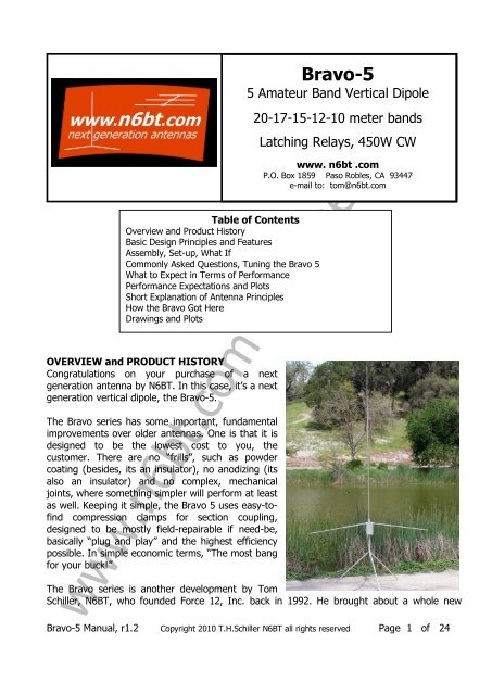
Bravo-5<br />
5 Amateur Band Vertical Dipole<br />
20-17-15-12-10 meter bands<br />
Latching Relays, 450W CW<br />
<strong>www</strong>. <strong>n6bt</strong> .<strong>com</strong><br />
P.O. Box 1859 Paso Robles, CA 93447<br />
e-mail to: tom@<strong>n6bt</strong>.<strong>com</strong><br />
The Bravo series is another development by Tom<br />
Schiller, N6BT, who founded Force 12, Inc. back in 1992. He brought about a whole new<br />
<strong>www</strong>.<strong>n6bt</strong>.<strong>com</strong> <strong>online</strong> <strong>copy</strong><br />
Bravo-5 Manual, r1.2 Copyright 2010 T.H.Schiller N6BT all rights reserved Page 1 of 24
generation of antennas back then, including the first trap-less tri-band Yagi, multi-band Yagis<br />
of many variations without traps, new verticals and vertical dipoles. After producing about<br />
24,000 antennas, he took a break and started a new venture in 2010 – <strong>n6bt</strong>.<strong>com</strong> – and the<br />
next generation of antennas was begun. After designing about 200 production antennas over<br />
the years, holding several radio patents, being an active DXer and contester with more than<br />
20 world records individually and with Team Vertical, one would expect something new. Here<br />
it is.<br />
Team Vertical began in 1997 and re-wrote the book on vertical antennas using creativity,<br />
empirical testing, plus building and using in <strong>com</strong>petition more than 300 verticals. Much of the<br />
Team’s history is contained in N6BT’s latest book, Array of Light Third Edition 2010. One of<br />
the antennas that was developed with the Team and used to set many records on 40 and 20<br />
meters was the called “Sigma” vertical dipole. It was given that name because it was the sum<br />
of what N6BT knew about verticals at that time. It was produced in many models from 80<br />
meters up through 70cm. Another model was remote-switched for 5 bands, 20 through 10.<br />
The 5-band vertical dipole was so good that it was even copied by at least one other<br />
<strong>com</strong>pany. Now after a break of a couple years to distil thoughts, the Bravo-5 is the next<br />
generation – a vertical dipole that is not only improved mechanically and visually, but also<br />
performance-wise.<br />
The Bravo-5 is physically full size on 10 and loaded with high-Q coils for 12, 15, 17 and 20<br />
meters. There are two segments on 20, providing full band coverage.<br />
BASIC DESIGN PRINCIPLES and FEATURES<br />
How to describe the Bravo series has been a bit of a challenge and the best description is that<br />
it is a vertical dipole with asymmetric feed and <strong>com</strong>pressed length tubing radials. The last part<br />
first: vertical dipole.<br />
A full size, straight vertical dipole is basically a half-wave dipole turned vertically and fed in the<br />
center, just like it would be as a horizontal dipole. In the horizontal configuration, it has a feed<br />
impedance of about 70 ohms, depending on its height above ground. In the vertical position,<br />
it has a feed impedance of around 90 ohms, giving a VSWR to 50 ohm coax of about 1.8:1.<br />
Nobody likes that very much, as the VSWR isn’t that coveted 1:1, so we shorten the length to<br />
move the feed impedance down to around 50 ohms. This is done in collaboration with the<br />
vertical section and the radials. Since there is no end loading at the top (no cross bar at the<br />
top of the vertical portion), the Bravo vertical section is made longer than one that is top<br />
loaded.<br />
The new Bravo vertical section is mechanically and visually superior. Rather then having the<br />
heavier vertical section to hold up the top cross bar, the Bravo vertical section is tapered,<br />
which gives a smaller visual footprint and also less wind load, while maintaining the<br />
performance characteristics of the top loaded vertical dipole. Making the vertical section on<br />
<strong>www</strong>.<strong>n6bt</strong>.<strong>com</strong> <strong>online</strong> <strong>copy</strong><br />
Bravo-5 Manual, r1.2 Copyright 2010 T.H.Schiller N6BT all rights reserved Page 2 of 24
the Bravo also moved the feed point to the bottom, not at the center of the previous design.<br />
This is much more user, visually and mechanically friendly.<br />
The Bravo’s two (2) tubing radials are shorter than full size. The appropriate length to have a<br />
50 ohm feed impedance for the vertical dipole is made up in the vertical length selection. The<br />
tubing radials are loaded very slightly on 10 and 12 meters. This places the feed point not at<br />
the typical, physical center; therefore, it is asymmetric. The loading in the radials and the<br />
loading in the vertical section are not identical.<br />
Putting the above together into the next generation, the Bravo-5 has these improvements<br />
over the previous designs:<br />
a) mechanically<br />
__single vertical element without the top end loading bar, making this antenna easier<br />
to build and erect, with less wind loading and, therefore, stronger in bad weather,<br />
without the tendency to rotate in the wind (as often happens with the top end loading<br />
cross bar);<br />
__safety-tilt radials slope downward from the main hub. The slight slant catches one’s<br />
eye, so it is easier to see and less likely to bump in to;<br />
__the tri-pod was always an option, but not any more – it <strong>com</strong>es with the antenna<br />
__box containing the loading coils has a weather-sealing gasket<br />
__box cover is easily removed for control cable connections, or to manually function<br />
the relays with a separate battery<br />
__stainless hardware is used where it should be used<br />
b) electrically<br />
__feed point is at the bottom, right where you want it<br />
__the feed line can now be dropped straight down – no more sloping off at a 45 angle<br />
__all loading is right at the bottom, within easy reach<br />
__the Bravo-5 uses latching relays, so the power is only applied for a short pulse and<br />
not continuously to remain on a band<br />
__the relay box can be controlled right at the antenna using a separate battery<br />
__the relay box is diode-protected so the voltage cannot be applied in the wrong<br />
polarity<br />
c) performance<br />
__efficiency is a on the order of 92% on 20 meters, increasing rapidly on 17 and being<br />
about 98-99% on the higher bands<br />
__actually has slightly more gain than the older series with the top end loading bar.<br />
d) cost – low cost and field repairable are major design goals<br />
__the “most bang for your buck”<br />
__use your own control cable – it connects to (2) European style barrier strips.<br />
__simple, easy to get <strong>com</strong>pression clamps<br />
__no need for powder coated or anodized parts<br />
__keep it simple<br />
<strong>www</strong>.<strong>n6bt</strong>.<strong>com</strong> <strong>online</strong> <strong>copy</strong><br />
Bravo-5 Manual, r1.2 Copyright 2010 T.H.Schiller N6BT all rights reserved Page 3 of 24
SPECIFICATIONS:<br />
Overall height will all vertical sections = ~9’<br />
Overall radial length with all sections = ~5.5’<br />
Weights: vertical sections = 1.5#, radials (2) = 2#, hub = 1.5#; tri-pod = 2.5# Total = 7.5#<br />
VSWR on all bands is 1.3:1 or less at resonance<br />
Power rating = 450w CW<br />
Computed efficiency:<br />
Efficiency % Total Loss in the Antenna<br />
10 meters 99+% -0.01dB<br />
12 meters 99+% -0.02<br />
15 meters 98 % -0.06<br />
17 meters 96+% -0.14<br />
20 meters 92 % -0.35dB<br />
Please be aware that there are emission exposure limits set by the FCC. All ground-based<br />
antennas will emit more energy at “people” level than elevated ones. Since this antenna is<br />
probably going to be used at ground level and possibly close to people, be careful to keep the<br />
power level as low as practical.<br />
Let’s put it together……..<br />
ASSEMBLY<br />
1. TOOLS and PARTS REQUIRED<br />
____ A. Tools required:<br />
1) blade screwdriver for <strong>com</strong>pression clamps<br />
a) can also use nut drivers on the <strong>com</strong>pression clamps<br />
b) they will be the #6 (1/4” dark red) and #8 (3/16” orange)<br />
2) nut driver for #10 nuts (3/8” – blue handle)<br />
____ B. Other<br />
1) tape measure<br />
__Note – for portable use, a tri-pod leg or the first long section on the radials<br />
(the .500” section) can be calibrated for the measurements you will need. The<br />
maximum is measurement anywhere is 33”.<br />
____ C. Hardware<br />
1) The majority of the hardware is stainless steel, except possibly for some of the<br />
<strong>com</strong>ponents in the <strong>com</strong>pression clamps. They are available in all stainless steel<br />
for harsh environments.<br />
____ D. Coax feed line with a UHF PL-259 connector<br />
1) Coax should be 50-ohm, such as RG-8X, RG-58, RG-8<br />
2) To keep the product cost as low as possible, this antenna is shipped with an<br />
<strong>www</strong>.<strong>n6bt</strong>.<strong>com</strong> <strong>online</strong> <strong>copy</strong><br />
Bravo-5 Manual, r1.2 Copyright 2010 T.H.Schiller N6BT all rights reserved Page 4 of 24
SET-UP<br />
integrated balun <strong>com</strong>posed of ferrite beads inside the relay box.<br />
2. ANTENNA AND TRI-POD<br />
____ A. This antenna has been fully assembled and tested before shipping<br />
1) all the <strong>com</strong>pression clamps are in place on the sections of tubing<br />
2) the tubing sections are telescoped inside each other<br />
3) the coils inside the coil box have been pre-set<br />
____ B. Please follow the drawing that gives the tubing length settings<br />
1) Snug the <strong>com</strong>pression clamps to secure the sections – just enough so the<br />
section(s) won’t slide, or turn<br />
2) No need to “crunch” the clamps.<br />
3) Nut drivers are the best method for managing the <strong>com</strong>pression clamps<br />
4) Using a spray lubricant, such as WD-40 or Tri-Flo will aid in keeping the sections<br />
easy to move. WD-40 will disappear over time and need to be replenished.<br />
____ C. Your particular installation is most likely not like our test facilities, so the<br />
antenna might not be exactly on frequency.<br />
1) If necessary, please follow the frequency adjustment procedure later in this<br />
manual<br />
____ D. Plug the legs into the tri-pod base. The legs simply slide in. If you like, tape can<br />
be used to secure them.<br />
____ E. Slide the assembled antenna into the tri-pod. The <strong>com</strong>pression clamp on the top<br />
of the tri-pod can be tightened as desired to keep the antenna from rotating in the<br />
wind.<br />
____ F. The Bravo-5 should be guyed at the base of the vertical section when installed in<br />
windy locations. Use non-conductive line – not metal guy cable.<br />
3. CHANGING BANDS<br />
____ A. The relay box can be controlled from the control box via the control cable, or<br />
right at the relay box using a separate battery.<br />
1) The relays are latching, so the voltage is only for a pulse to either reset the<br />
relays, or set them again.<br />
2) The relay box is diode-protected so the voltage cannot be applied in the wrong<br />
polarity.<br />
<strong>www</strong>.<strong>n6bt</strong>.<strong>com</strong> <strong>online</strong> <strong>copy</strong><br />
Bravo-5 Manual, r1.2 Copyright 2010 T.H.Schiller N6BT all rights reserved Page 5 of 24
3) The relays pull in at about 8.5VDC. There are either one or two diodes that<br />
appear in the control circuit. This means there is a maximum voltage drop of<br />
about 1.5V. The minimum supply voltage at the relay box (not at the control<br />
box), will be a 10VDC. A brand new 9V battery might have enough voltage to<br />
cycle the relays right at the relay box.<br />
____ B. The control cable requires 7 conductors and 12VDC at the control box for typical<br />
control cable lengths.<br />
1) This cable can be small conductors, as the current requirement is quite small,<br />
plus only being a pulse. Using typical 8-conductor rotator cable is great and<br />
using a pair of the small 4-conductor telephone cables will work, too. When<br />
using 8-conductor cables, double up on the ground (-, negative) lead.<br />
2) Connect your cable to the control box, following the wiring diagram.<br />
3) Connect the cable to the antenna relay box, bringing it up through the hole and<br />
then to the barrier strip terminals.<br />
____ C. The coil box cover can be left off if desired<br />
1) there is a gasket for the coil box cover to assist in weather-sealing<br />
2) there are (4) screws for the coil box cover for permanent installations<br />
3) if you do not seal the cover, place the gasket and screws in a safe place you can<br />
find when you want them<br />
____ D. To change bands using the control box<br />
1) be sure it is connected properly to 12VDC (typically 13.8 if used to power the<br />
rig) supply<br />
2) press the “RESET” push button. The left-hand light will light and the relays in the<br />
relay box will be reset to their unlatched state.<br />
3) select the band of choice using the rotary switch<br />
4) press the “SET” push button. The right-hand light will light and the appropriate<br />
relays in the relay box will be set<br />
____ E. To change bands right at the relay box using a separate battery<br />
1) the battery leads need to be touched to the proper barrier strip connections<br />
2) to reset the relays, touch the battery negative lead to the ground terminal and<br />
touch the positive lead from the battery to “20L” on the terminal strip.<br />
3) to select the band of choice, touch the battery negative lead to the ground<br />
terminal and touch the positive lead from the battery to the terminal<br />
corresponding to the band of choice.<br />
____ F. Note – if the antenna is knocked over, or falls down, the relays might unlatch. In<br />
this case, simply reset the relay box and set your band again.<br />
4. WHAT IF<br />
____ A. What if the VSWR is way high, like 3:1 when I hook it up?<br />
<strong>www</strong>.<strong>n6bt</strong>.<strong>com</strong> <strong>online</strong> <strong>copy</strong><br />
Bravo-5 Manual, r1.2 Copyright 2010 T.H.Schiller N6BT all rights reserved Page 6 of 24
1) Most likely this is a coax feed line problem. Check for continuity through the<br />
coax connectors and be sure the shield and center conductor are not shorted<br />
somewhere.<br />
____ B. What if when I use a meter to check tuning, I can’t get it to work right?<br />
1) Meters, like the popular MFJ, can have a couple conditions where they are not<br />
useful.<br />
2) Meters send out their own, very low power signal and read the “return.” If there<br />
happens to be additional RF nearby, such as from AM broadcast, the meter<br />
might be <strong>com</strong>pletely ineffective, as it will also receive the Rf from the broadcast<br />
station. This is because the meters normally have a wide-open front end and<br />
receive everything.<br />
3) On the MFJ dual meter device, people will sometimes use the righthand meter<br />
that is calibrated in ohms to tune an antenna. They will move the tuning knob<br />
until the meter reads 50 and then read the frequency, plus reading the VSWR on<br />
the lefthand meter. The lefthand meter will more often than not, read a high<br />
VSWR. This is an incorrect procedure.<br />
a) Use the lefthand meter only to tune an antenna. Tune the knob carefully<br />
and slowly, looking for the dip in the lefthand meter. Set the tuning for the<br />
lowest point in the meter’s reading and you will have both the frequency of the<br />
antenna and its associated VSWR at that frequency.<br />
5. COMMONLY ASKED QUESTIONS<br />
____ A. Do I need to change the antenna to go on another band?<br />
To listen on another band, you can use the antenna on whatever band it is tuned for. It<br />
will not be as effective (i.e. sensitive) as when it is properly tuned.<br />
____ B. Can I use a tuner with the antenna?<br />
It should not be necessary, unless you want to operate outside an amateur band. In<br />
this case, it would be wise to use reduced power.<br />
Using a tuner on either receive and transmit will not be as efficient as when the<br />
antenna is properly tuned.<br />
____ C. Do I need radials with the Bravo-5?<br />
No – although the Bravo-5 might resemble a general design of a ¼ wavelength vertical<br />
with 2 radials, it is actually an asymmetrically fed, loaded radial vertical dipole. It is<br />
“self-contained” and does not need any additional radials.<br />
____ D. Can I add radials under the Bravo-5 to improve the ground conductivity?<br />
Absolutely!<br />
The efficiency of the antenna is always a constant, regardless of the ground or<br />
surrounding area / terrain. The ground does have a significant contribution to the<br />
efficiency of the antenna system, which is not only the antenna, but also the ground<br />
and surroundings. Objects like nearby metal buildings usually are detrimental, as they<br />
can block signals, both <strong>com</strong>ing and going.<br />
<strong>www</strong>.<strong>n6bt</strong>.<strong>com</strong> <strong>online</strong> <strong>copy</strong><br />
Bravo-5 Manual, r1.2 Copyright 2010 T.H.Schiller N6BT all rights reserved Page 7 of 24
The conductivity of the ground is a major contributor to the system efficiency. If the<br />
ground is extremely poor, such as granite, the vertically-polarized energy of the<br />
antenna is negatively enhanced. If, on the other hand, the ground is rich dirt, it is<br />
much better. The ultimate for a vertical is salt water, which both creates essentially a<br />
loss-less near-field for the energy, but also an unobstructed plane going out for some<br />
distance.<br />
The result of poor vs. great ground is the low angle energy. As the ground is improved,<br />
the low angle energy is increased. Salt water, for example, can support energy down to<br />
perhaps 1 degree.<br />
If you are not enjoying the beach and have the Bravo-5 in close proximity to salt water,<br />
you can take random lengths of wire and run them away from the base of the antenna.<br />
The lengths are not critical. In general, the more wire, the better, as <strong>com</strong>pared to a<br />
few long runs. Do not connect them to the antenna!<br />
Regarding verticals and salt water – my book, Array of Light has a lot of coverage on<br />
this subject. Briefly, the antenna needs to be quite close to the water. Team Vertical<br />
installs our <strong>com</strong>petition antennas within ¼ wavelength to in the water (above, of<br />
course) whenever possible. A distance of ¾ wavelength from the salt-water boundary<br />
is about the limit. For reference, a distance of ¾ wavelength on 20 is about 52’. A ¼<br />
wavelength would be about 17’. Remember to take into account surf, general wave<br />
action and tides. To calculate a half wavelength on any frequency for this purpose,<br />
divide 492 by the frequency in MHz – right, 492, not 468. The latter number is for a<br />
wire antenna and takes into account the probable velocity factor of the wire. We are<br />
dealing in air.<br />
How much improvement might you get from adding wire? In carefully run tests, we<br />
have measured 2-3dB improvement when the antenna is over good ground. If it is over<br />
incredibly poor ground, it was more like 8-10dB, which seems impossible, but it was<br />
due to the low angle energy being “recovered” by the improved ground conductivity.<br />
6. TUNING THE BRAVO-5<br />
____ A. If the Bravo-5 is not on frequency, meaning that it does not cover the selected<br />
band with a reasonable VSWR (i.e. best VSWR is way low below a band) is this section.<br />
____ B. The Bravo-5 <strong>com</strong>es already tested and tuned. It is certainly possible that the<br />
antenna will tune up differently in all the <strong>com</strong>binations of locations, such as height<br />
above ground and the characteristics of the ground.<br />
____ C. Please remember that an antenna does not need to be 1:1 VSWR point to work<br />
properly. (N6BT’s great book on antennas, Array of Light, Third Edition, cover this is<br />
<strong>www</strong>.<strong>n6bt</strong>.<strong>com</strong> <strong>online</strong> <strong>copy</strong><br />
Bravo-5 Manual, r1.2 Copyright 2010 T.H.Schiller N6BT all rights reserved Page 8 of 24
detail.)<br />
1. A VSWR below 2:1 should be fine for most equipment and is not indicate the<br />
antenna is operating poorly. All it means is that the feed point is not matched to<br />
50 ohms. A 2:1 VSWR will mean it is either 2 times or ½ of 50 ohms and in this<br />
case, it will be the latter, ½ of 50 ohms, or about 25 ohms. This is often a result<br />
when the antenna is being used at higher heights above ground.<br />
2. The installed hairpin matching coil (soldered onto the PCB) can be adjusted by<br />
expanding the turns on the coil. Expand the turns slightly and note if the VSWR<br />
improves. If does, then continue to expand the turns.<br />
3. If expanding the turns on the hairpin matching coil results in a higher VSWR,<br />
please e-mail tom @ <strong>n6bt</strong>.<strong>com</strong><br />
____ D. If one or more of the bands are significantly off frequency (i.e. the lowest VSWR<br />
is obviously way out of the band and the VSWR is higher than 1.5:1) the coils for the<br />
bands need to be adjusted. Please do it carefully.<br />
1. the coils are in sequence and add together. This means that 15 meters uses the<br />
12 meter coil and the 15 meter coil. 17 meters uses the 12, 15 and 17 meter<br />
coils.<br />
2. since the coils are additive, they must be adjusted in sequence<br />
____ E. To begin, reset the relays – this will place the antenna in 20 LOW<br />
1. next - set the relay box to 10 meters<br />
a) there are no coils in the circuit when on 10 meters<br />
b) this is the “native mode” of the antenna, which means it is the<br />
antenna as it is physically built, along with the stray inductance in<br />
the relay box<br />
2. the point of lowest VSWR is set at the factory to about 28.300 MHz and<br />
should be minimal, if at all – the antenna is extremely broadbanded on 10<br />
meters and can cover down to almost 27 MHz and up to almost 30 MHz<br />
a) to change this frequency requires changing the length of the<br />
radials, the vertical section, or possibly both<br />
b) change the length of the radials first<br />
1) lengthening the radials will lower the frequency and there is<br />
not much adjustment available<br />
2) shortening the radials will raise the frequency<br />
3) the same holds for the vertical sections and adjusting the<br />
vertical sections will make a more rapid change than<br />
changing the radial lengths<br />
____ F. To set the remaining bands – again, it is not necessary to be “exactly perfect” on<br />
the frequency settings. The antenna is broadbanded and the VSWR should be about<br />
1.5:a or less across the bands, except for 20 meters<br />
1. set the relay box to 12 meters<br />
a) adjust both 12 meter coils for about 24.925 MHz<br />
2. set the relay box to 15 meters<br />
<strong>www</strong>.<strong>n6bt</strong>.<strong>com</strong> <strong>online</strong> <strong>copy</strong><br />
Bravo-5 Manual, r1.2 Copyright 2010 T.H.Schiller N6BT all rights reserved Page 9 of 24
a) adjust both 15 meter coils for about 21.225 MHz<br />
b) do not go back and adjust the 12 meter coils<br />
3. set the relay box to 17 meters<br />
a) adjust both 17 meter coils for about 18.125 MHz<br />
b) do not go back and adjust the 12 or 15 meter coils<br />
4. set the relay box to 20 LOW (this is the same as hitting “RESET”)<br />
a) the 20 meter band is covered in 2 segments and this will set the<br />
lower frequency<br />
b) adjust both 20 meter coils for about 14.150 MHz<br />
c) do not go back and adjust any other coils<br />
5. set the relay box for 20 HI and check the frequency. It should have<br />
mover up to cover the phone portion of the band.<br />
WHAT TO EXPECT IN TERMS OF PERFORMANCE<br />
Vertical antennas installed not far above ground will have a single energy lobe <strong>com</strong>ing off at<br />
about 20 degrees. If the vertical antenna is installed over salt water, or very close to it, this<br />
energy lobe will be lowered considerably, with energy now down to about 1 degree, which is<br />
as good as it gets. Horizontal antennas, even stacked Yagis, cannot <strong>com</strong>pete with verticals<br />
and vertical arrays over salt water. This vertical antenna has a small footprint and will perform<br />
quite well when properly installed. It is the product from almost 20 years of using vertical<br />
antennas in world-wide <strong>com</strong>petition by Team Vertical. As mentioned earlier, the Team has set<br />
more than 20 world records and re-wrote the book on verticals. Much information on verticals<br />
that you won’t find any other place is contained in N6BT’s book, Array of Light, Third Edition.<br />
The ground under the vertical can be improved, especially when it is installed over sand or<br />
rock (granite is quite poor). Laying wire down underneath the antenna in length as long as<br />
practical and as many wires as practical, will improve the ground conductivity in what is called<br />
the “”near field.” This is the area closest to the vertical and is where the most loss in the<br />
ground will occur. Improving the ground will reduce these ground losses, with improved<br />
system performance and even a lowering of the lobe. “System performance” includes the<br />
antenna and the ground. The efficiency of the antenna itself will be constant, so improving the<br />
ground conductivity pertains to the ground portion of the system.<br />
Q: How is a vertical <strong>com</strong>pared to a horizontal antenna, such as a full size dipole (e.g. not a<br />
Windom, which is more of a top loaded wire vertical)?<br />
Vertical antennas over ground will do a good job, especially considering their small footprint. A<br />
good, full size dipole at a reasonable height and in the clear will often be more effective than<br />
a vertical. The dipole will favor the stations off to the sides, because the dipole is directional.<br />
A horizontal dipole will have nulls off the ends and the depth of the nulls depends mostly on<br />
the height above ground and also surrounding objects. A vertical is omni-directional, meaning<br />
<strong>www</strong>.<strong>n6bt</strong>.<strong>com</strong> <strong>online</strong> <strong>copy</strong><br />
Bravo-5 Manual, r1.2 Copyright 2010 T.H.Schiller N6BT all rights reserved Page 10 of 24
it emits and receives energy equally in all directions.<br />
SHORT EXPLANATION OF ANTENNA PRINCIPLES<br />
Verticals over ground will lose some energy into the ground, which is why the ground should<br />
be as good as possible; good = electrically good and a metal roof is quite nice for this<br />
purpose. Salt water is incredible. In a different manner, the horizontal antenna will gain<br />
energy from ground effects, called “ground reflection gain.” In practical terms, a horizontal<br />
dipole will achieve about 2dB gain <strong>com</strong>pared to the isotropic source (properly stated 2dBi) due<br />
to the pattern being made into a figure 8 when the dipole is above<br />
ground. The side energy of the dipole, however, is reduced in order<br />
to achieve this 2dBi improvement.<br />
If we begin with what is called the “isotropic radiator” (strictly<br />
theoretical), it is a sphere, with a single point source of energy<br />
located exactly at the center. It is emitting energy equally in all<br />
directions until it runs out – which is the skin of the balloon. It is<br />
also located out in “free space” and looks like this photo:<br />
The horizontal antenna is, of course, not located in free space,<br />
but over ground. This causes the energy in the balloon to be<br />
redistributed like the next photo. As you can see, the balloon has<br />
been reformed, with more of it in 2 directions, which are<br />
broadside to the dipole. There is less energy where Tom’s fingers<br />
are squeezing the balloon, which is in the direction of the ends of<br />
the dipole. By the ground effect of redistributing the energy, the<br />
dipole has 2dB gain over the isotropic source. This is known as 2dBi – 2dB <strong>com</strong>pared to the<br />
isotropic source.<br />
The horizontal will also benefit from ground reflection gain on the order of 5dB. This is the<br />
effect of reflected energy <strong>com</strong>bining way out, in the “far field.” If the vertical were perfect, in<br />
terms of not losing any energy to the ground, but still being over ground, the vertical will be<br />
about 7dB behind the dipole (2dB + 5dB). The take-off angle of the antennas <strong>com</strong>es into play<br />
here and although a single vertical will typically be less than a good horizontal antenna,<br />
adding a second element to the vertical will improve its performance by about 4dB and make<br />
it a directive array, as well.<br />
ANTENNA PLOTS<br />
There are several pages of <strong>com</strong>puter antenna models in this manual. Each page contains<br />
much information concerning the probable performance of the Bravo-5K vertical.<br />
If you are interested in adding a second element for an array, or making a larger array, please<br />
<strong>www</strong>.<strong>n6bt</strong>.<strong>com</strong> <strong>online</strong> <strong>copy</strong><br />
Bravo-5 Manual, r1.2 Copyright 2010 T.H.Schiller N6BT all rights reserved Page 11 of 24
send off an e-mail. We will be glad to assist you.<br />
We can also provide information for you on your DXpeditions.<br />
Thank you for selecting our product and let us know how it performs for you!<br />
---------------NOTICE----------------<br />
BE SURE THIS ANTENNA DOES NOT COME NEAR TO, OR IN<br />
CONTACT WITH POWER LINES, AS YOU CAN BE<br />
SERIOUSLY INJURED OR KILLED.<br />
BE AWARE OF OTHER DANGERS AND ALWAYS CHECK THE<br />
AREA MORE THAN ONCE BEFORE ERECTING ANY ANTENNA.<br />
Supplier: <strong>www</strong>. <strong>n6bt</strong>. <strong>com</strong> Warranty and Limitation of Liability<br />
The supplier warrants its products for a period of one year from date of purchase. This warranty covers defects in manufacturing and<br />
workmanship. The supplier has the discretion of honoring the warranty if the product appears to have been abused, used in a manner that<br />
exceeds the specifications of the unit, or a use for which the product was not designed. This warranty does not cover transportation,<br />
installation, punitive, or other costs that may be incurred from warranty repair, or installation. The supplier must be notified and warranty<br />
repair authorized (only by the supplier who will issue a return material authorization, an RMA) before the supplier will accept any product<br />
returns. Please advise the date of purchase, model number, serial number if there is one and a brief description of the problem. There is a<br />
30% restocking fee on products returned unused with an RMA issued by the supplier, at its sole discretion.<br />
The customer, installer and user of these products individually and collectively acknowledge that these products can cause injury or death<br />
and individually and collectively accept full responsibility and liability for any and all personal and property damage (direct, indirect and<br />
punitive) caused during installation and/or use of these products and hold the supplier harmless for such damage.<br />
(warranty notice date 4/1/2010)<br />
<strong>www</strong>.<strong>n6bt</strong>.<strong>com</strong> <strong>online</strong> <strong>copy</strong><br />
Bravo-5 Manual, r1.2 Copyright 2010 T.H.Schiller N6BT all rights reserved Page 12 of 24
<strong>www</strong>.<strong>n6bt</strong>.<strong>com</strong> <strong>online</strong> <strong>copy</strong><br />
Bravo-5 Manual, r1.2 Copyright 2010 T.H.Schiller N6BT all rights reserved Page 13 of 24
<strong>www</strong>.<strong>n6bt</strong>.<strong>com</strong> <strong>online</strong> <strong>copy</strong><br />
Bravo-5 Manual, r1.2 Copyright 2010 T.H.Schiller N6BT all rights reserved Page 14 of 24
<strong>www</strong>.<strong>n6bt</strong>.<strong>com</strong> <strong>online</strong> <strong>copy</strong><br />
Bravo-5 Manual, r1.2 Copyright 2010 T.H.Schiller N6BT all rights reserved Page 15 of 24
<strong>www</strong>.<strong>n6bt</strong>.<strong>com</strong> <strong>online</strong> <strong>copy</strong><br />
Bravo-5 Manual, r1.2 Copyright 2010 T.H.Schiller N6BT all rights reserved Page 16 of 24
<strong>www</strong>.<strong>n6bt</strong>.<strong>com</strong> <strong>online</strong> <strong>copy</strong><br />
Bravo-5 Manual, r1.2 Copyright 2010 T.H.Schiller N6BT all rights reserved Page 17 of 24
<strong>www</strong>.<strong>n6bt</strong>.<strong>com</strong> <strong>online</strong> <strong>copy</strong><br />
Bravo-5 Manual, r1.2 Copyright 2010 T.H.Schiller N6BT all rights reserved Page 18 of 24
<strong>www</strong>.<strong>n6bt</strong>.<strong>com</strong> <strong>online</strong> <strong>copy</strong><br />
Bravo-5 Manual, r1.2 Copyright 2010 T.H.Schiller N6BT all rights reserved Page 19 of 24
<strong>www</strong>.<strong>n6bt</strong>.<strong>com</strong> <strong>online</strong> <strong>copy</strong><br />
Bravo-5 Manual, r1.2 Copyright 2010 T.H.Schiller N6BT all rights reserved Page 20 of 24
<strong>www</strong>.<strong>n6bt</strong>.<strong>com</strong> <strong>online</strong> <strong>copy</strong><br />
Bravo-5 Manual, r1.2 Copyright 2010 T.H.Schiller N6BT all rights reserved Page 21 of 24
<strong>www</strong>.<strong>n6bt</strong>.<strong>com</strong> <strong>online</strong> <strong>copy</strong><br />
Bravo-5 Manual, r1.2 Copyright 2010 T.H.Schiller N6BT all rights reserved Page 22 of 24
<strong>www</strong>.<strong>n6bt</strong>.<strong>com</strong> <strong>online</strong> <strong>copy</strong><br />
Bravo-5 Manual, r1.2 Copyright 2010 T.H.Schiller N6BT all rights reserved Page 23 of 24
<strong>www</strong>.<strong>n6bt</strong>.<strong>com</strong> <strong>online</strong> <strong>copy</strong><br />
Bravo-5 Manual, r1.2 Copyright 2010 T.H.Schiller N6BT all rights reserved Page 24 of 24
<strong>www</strong>.<strong>n6bt</strong>.<strong>com</strong> <strong>online</strong> <strong>copy</strong><br />
Bravo-5 Manual, r1.2 Copyright 2010 T.H.Schiller N6BT all rights reserved Page 25 of 24
<strong>www</strong>.<strong>n6bt</strong>.<strong>com</strong> <strong>online</strong> <strong>copy</strong><br />
Bravo-5 Manual, r1.2 Copyright 2010 T.H.Schiller N6BT all rights reserved Page 26 of 24
Last page for notes…………………………………….<br />
<strong>www</strong>.<strong>n6bt</strong>.<strong>com</strong> <strong>online</strong> <strong>copy</strong><br />
Bravo-5 Manual, r1.2 Copyright 2010 T.H.Schiller N6BT all rights reserved Page 27 of 24