

GRUNDFOS INSTRUCTIONS - VBS irrigatie-technieken
GRUNDFOS INSTRUCTIONS - VBS irrigatie-technieken
GRUNDFOS INSTRUCTIONS - VBS irrigatie-technieken

You also want an ePaper? Increase the reach of your titles
YUMPU automatically turns print PDFs into web optimized ePapers that Google loves.
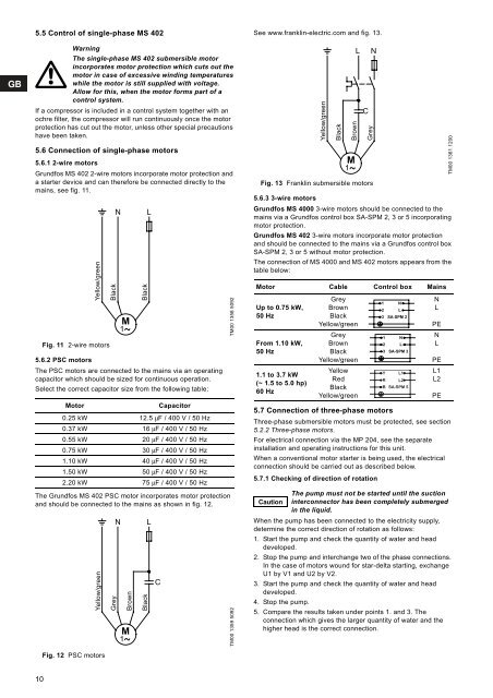
5.5 Control of single-phase MS 402<br />
If a compressor is included in a control system together with an<br />
ochre filter, the compressor will run continuously once the motor<br />
protection has cut out the motor, unless other special precautions<br />
have been taken.<br />
5.6 Connection of single-phase motors<br />
5.6.1 2-wire motors<br />
Grundfos MS 402 2-wire motors incorporate motor protection and<br />
a starter device and can therefore be connected directly to the<br />
mains, see fig. 11.<br />
10<br />
Warning<br />
The single-phase MS 402 submersible motor<br />
incorporates motor protection which cuts out the<br />
motor in case of excessive winding temperatures<br />
while the motor is still supplied with voltage.<br />
Allow for this, when the motor forms part of a<br />
control system.<br />
Yellow/green<br />
Fig. 11 2-wire motors<br />
5.6.2 PSC motors<br />
The PSC motors are connected to the mains via an operating<br />
capacitor which should be sized for continuous operation.<br />
Select the correct capacitor size from the following table:<br />
Motor Capacitor<br />
0.25 kW 12.5 μF / 400 V / 50 Hz<br />
0.37 kW 16 μF / 400 V / 50 Hz<br />
0.55 kW 20 μF / 400 V / 50 Hz<br />
0.75 kW 30 μF / 400 V / 50 Hz<br />
1.10 kW 40 μF / 400 V / 50 Hz<br />
1.50 kW 50 μF / 400 V / 50 Hz<br />
2.20 kW 75 μF / 400 V / 50 Hz<br />
The Grundfos MS 402 PSC motor incorporates motor protection<br />
and should be connected to the mains as shown in fig. 12.<br />
Yellow/green<br />
Fig. 12 PSC motors<br />
Black<br />
Grey<br />
N L<br />
M<br />
1<br />
Black<br />
N L<br />
Brown<br />
M<br />
1<br />
Black<br />
C<br />
TM00 1358 5092<br />
TM00 1359 5092<br />
See www.franklin-electric.com and fig. 13.<br />
Fig. 13 Franklin submersible motors<br />
5.6.3 3-wire motors<br />
Grundfos MS 4000 3-wire motors should be connected to the<br />
mains via a Grundfos control box SA-SPM 2, 3 or 5 incorporating<br />
motor protection.<br />
Grundfos MS 402 3-wire motors incorporate motor protection<br />
and should be connected to the mains via a Grundfos control box<br />
SA-SPM 2, 3 or 5 without motor protection.<br />
The connection of MS 4000 and MS 402 motors appears from the<br />
table below:<br />
Motor Cable Control box Mains<br />
Up to 0.75 kW,<br />
50 Hz<br />
From 1.10 kW,<br />
50 Hz<br />
1.1 to 3.7 kW<br />
(~ 1.5 to 5.0 hp)<br />
60 Hz<br />
Grey<br />
Brown<br />
Black<br />
Yellow/green<br />
Grey<br />
Brown<br />
Black<br />
Yellow/green<br />
5.7 Connection of three-phase motors<br />
Three-phase submersible motors must be protected, see section<br />
5.2.2 Three-phase motors.<br />
For electrical connection via the MP 204, see the separate<br />
installation and operating instructions for this unit.<br />
When a conventional motor starter is being used, the electrical<br />
connection should be carried out as described below.<br />
5.7.1 Checking of direction of rotation<br />
Caution<br />
Yellow/green<br />
Black<br />
Brown<br />
M<br />
1<br />
Yellow<br />
Red<br />
Black<br />
Yellow/green<br />
L N<br />
When the pump has been connected to the electricity supply,<br />
determine the correct direction of rotation as follows:<br />
1. Start the pump and check the quantity of water and head<br />
developed.<br />
2. Stop the pump and interchange two of the phase connections.<br />
In the case of motors wound for star-delta starting, exchange<br />
U1 by V1 and U2 by V2.<br />
3. Start the pump and check the quantity of water and head<br />
developed.<br />
4. Stop the pump.<br />
5. Compare the results taken under points 1. and 3. The<br />
connection which gives the larger quantity of water and the<br />
higher head is the correct connection.<br />
C<br />
Grey<br />
3 SA-SPM 2<br />
N<br />
L<br />
PE<br />
N<br />
L<br />
PE<br />
L1<br />
L2<br />
PE<br />
The pump must not be started until the suction<br />
interconnector has been completely submerged<br />
in the liquid.<br />
1<br />
2<br />
1<br />
2<br />
N<br />
L<br />
N<br />
L<br />
3 SA-SPM 3<br />
Y<br />
R<br />
L1<br />
L2<br />
B SA-SPM 5<br />
TM00 1361 1200