08 Vosteen_E_Umbruch - Vosteen Consulting GmbH
08 Vosteen_E_Umbruch - Vosteen Consulting GmbH
08 Vosteen_E_Umbruch - Vosteen Consulting GmbH

Create successful ePaper yourself
Turn your PDF publications into a flip-book with our unique Google optimized e-Paper software.
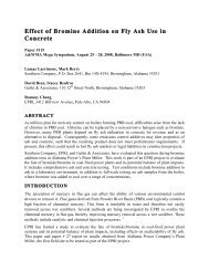
Thermography of Rotary Kilns<br />
Slag surface temperature<br />
in °C<br />
1500<br />
1400<br />
1300<br />
1200<br />
1100<br />
1000<br />
0 1 2 3 4 5 6 7 8 9 10 11 12 13<br />
Distance x from kiln entrance in m<br />
thermocouple temperature), has to be limited<br />
with respect to the slag’s melting behaviour,<br />
as will be discussed later.<br />
Evaluation of the Local<br />
Temperature Differences<br />
The evaluation of the local differences between<br />
the inner and outer temperatures is<br />
based on well-known laws of quasi stationary<br />
heat transfer, see Figure 7. The partial<br />
temperature difference (inner_slag_surface – outer_steel_shell_surface)<br />
as well as the total temperature<br />
difference (inner_slag_surface – environment)<br />
stand for the corresponding sums of heat<br />
transfer resistances. Therefore the thermographically<br />
measured ratio of these two<br />
temperature differences<br />
inner_slag_surface – outer_steel_shell_surface<br />
= –––––––––––––––––––––––––––––– (1)<br />
inner_slag_surface – environment<br />
can be interpreted as well as the ratio of the<br />
corresponding heat transfer resistances:<br />
Rslag_layer +Pbrick + Rair_gap + Rsteel_shell<br />
= –––––––––––––––––––––––––––––– (2)<br />
Rslag_layer +Rbrick +Rair_gap +<br />
+Rsteel_shell +Router_heat_transfer<br />
(x) as a function of the distance x from the<br />
kiln entrance gives a qualitative image of the<br />
axial wall thickness profile; see Figure 8<br />
as an example of KILN A, demonstrating<br />
KILN A<br />
Excess temperature<br />
Figure 6b. Inner axial temperature profiles in KILN A<br />
along different axial lines (at the right hand,<br />
left hand and upper kiln side).<br />
ψ<br />
1<br />
0.95<br />
0.9<br />
0.85<br />
0.8<br />
0.75<br />
0.7<br />
r<br />
ϑ Outer steel shell<br />
ϑEnvironment<br />
ϑ Slag surface<br />
heightened brick wear in the kiln’s hotter<br />
middle part, caused there by the highest local<br />
heat burden, see excess-temperature in Figure<br />
6b.<br />
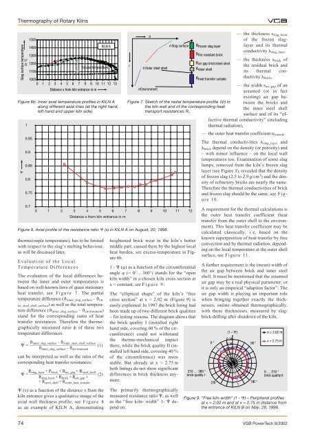
1 - () as a function of the circumferential<br />
angle (= 0°... 360°) stands for the “open<br />
kiln width” in a chosen kiln cross section at<br />
x = constant, see Figure 9:<br />
The “elliptical shape” of the kiln’s “free<br />
cross section” at x = 2.02 m (Figure 9) is<br />
easily explained: In 1997 the brick lining had<br />
been made up of two different brick qualities<br />
– for testing reasons. The diagram shows that<br />
the brick quality I (installed right<br />
hand side, covering 60 % of the circumference)<br />
could not withstand<br />
the thermo-mechanical impact<br />
there, while the brick quality II (installed<br />
left hand side, covering 40 %<br />
of the circumference) was more<br />
stable. But already at x = 2.75 m<br />
both linings do not show significant<br />
differences in brick thickness anymore.<br />
The primarily thermographically<br />
measured resistance ratio , as well<br />
as the “free kiln- width” 1- depend<br />
on:<br />
ϑ<br />
Rfrozen slag layer<br />
Rfire resistant brick<br />
Rair gap brick/steel shell<br />
Rsteel shell<br />
Rheat transfer outside<br />
Figure 7. Sketch of the radial temperature profile ϑ(r) in<br />
the kiln wall and of the corresponding heat<br />
transport resistances Ri.<br />
0 1 2 3 4 5 6 7 8 9 10 11 12<br />
Distance x from kiln entrance in m<br />
Figure 8. Axial profile of the resistance ratio Ψ (x) in KILN A on August, 20, 1998.<br />
210 … 360 °<br />
brick quality I<br />
— the thickness sslag_layer<br />
of the frozen slaglayer<br />
and its thermal<br />
conductivity slag_layer<br />
— the thickness sbrick of<br />
the residual brick and<br />
its thermal conductivity<br />
brick,<br />
— the width sair_gap of an<br />
assumed (or in fact<br />
existing) air gap between<br />
the bricks and<br />
the inner steel shell<br />
surface and of its “effective<br />
thermal conductivity” (including<br />
thermal radiation),<br />
— the outer heat transfer coefficient outside.<br />
The thermal conductivities slag_layer and<br />
brick depend on the density (or porosity) and<br />
– with minor influence – on the local wall<br />
temperatures too. Examination of some slag<br />
lumps, removed from the kiln’s frozen slag<br />
layer (see Figure 3), revealed that the density<br />
of frozen slag (2.5 to 2.9 g/cm 3 ) and the density<br />
of refractory bricks are nearly the same.<br />
Therefore the thermal conductivities of brick<br />
and frozen slag should be the same, see Figure<br />
10.<br />
A requirement for the thermal calculations is<br />
the outer heat transfer coefficient (heat<br />
transfer from the outer shell to the environment).<br />
This heat transfer coefficient may be<br />
calculated classically, i. e. based on the<br />
known superposition of heat transfer by free<br />
convection and by thermal radiation, depending<br />
on the local temperature at the outer shell<br />
surface, see Figure 11.<br />
A further requirement is the (mean) width of<br />
the air gap between brick and inner steel<br />
shell. It must be mentioned that the assumed<br />
air gap may be a real physical parameter; or<br />
it is only an empirical “adaption factor”: The<br />
air gap width is playing an important role<br />
when bringing together exactly the thicknesses,<br />
online obtained thermographically,<br />
with those thicknesses, measured by slag/<br />
brick-drilling after shutdown of the kiln.<br />
x = 2.02 m<br />
x = 2.75 m<br />
74 VGB PowerTech 9/2002<br />
0 °<br />
270 °<br />
(1 – Ψ)<br />
0.18<br />
0.16<br />
m 0.14<br />
0.12<br />
0.10<br />
0.<strong>08</strong><br />
90 °<br />
180 °<br />
0 … 210 °<br />
brick quality II<br />
Figure 9. “Free kiln-width“ (1 - Ψ) – Peripheral profiles<br />
at x = 2.02 m and at x = 2.75 m distance from<br />
the entrance of KILN B on May, 28, 1998.