08 Vosteen_E_Umbruch - Vosteen Consulting GmbH
08 Vosteen_E_Umbruch - Vosteen Consulting GmbH
08 Vosteen_E_Umbruch - Vosteen Consulting GmbH

You also want an ePaper? Increase the reach of your titles
YUMPU automatically turns print PDFs into web optimized ePapers that Google loves.
Kurzfassung<br />
Simultane innere und äußere<br />
Thermographie an Drehrohröfen von<br />
Sonderabfall-Verbrennungsanlagen<br />
– Kontrolliertes Pelzen verlängert die<br />
Ofenstandzeit erheblich<br />
Drehrohröfen von Sonderabfall-Verbrennungsanlagen<br />
(SVA) werden mit Al2O3-reichen feuerfesten<br />
Steinen ausgemauert (250 mm bis<br />
300 mm ursprüngliche Steindicke), um den<br />
tragenden äußeren Stahlmantel vor den hohen<br />
Ofen-Innentemperaturen zu schützen. Die kostenintensive<br />
Ausmauerung (rund 300 000 i)<br />
sollte ihrerseits gegen rapiden Verschleiß geschützt<br />
werden. Jeder direkte Kontakt von<br />
schmelzflüssiger Schlacke mit der Steinoberfläche<br />
fördert den Steinverschleiß. Im Fall<br />
„verschlackender Hochtemperatur-Verbrennung“<br />
mit Austrag schmelzflüssiger Schlacke<br />
wird die Ofenausmauerung jedoch – im Prinzip<br />
– nicht stärker gefährdet als im Fall „veraschender<br />
Niedertemperatur-Verbrennung“<br />
mit Trockentaschung, ganz im Gegenteil, sofern<br />
nur der Drehrohrofen im richtigen Temperaturbereich<br />
zwischen „zu heiß“ und „zu kalt“<br />
betrieben wird: Die Innentemperatur muss<br />
einerseits hoch genug sein, um die Asche<br />
überhaupt aufzuschmelzen, sie sollte andererseits<br />
aber niedrig genug bleiben, um einen –<br />
auf die Steinoberfläche aufziehenden und an<br />
ihr anfrierenden – Schlackepelz aufrecht zu erhalten.<br />
Aufziehen der Schlacke und Erstarren<br />
zum schützenden Pelz beruhen auf dem radialen<br />
Wärmeabtransport durch die „mehrschichtige<br />
Drehrohrwand“. Nur im Fall „verschlackender<br />
Hochtemperatur-Verbrennung“ wird<br />
es überhaupt möglich, einen solchen Pelz zu<br />
erzeugen und überall dauerhaft aufrecht zu erhalten.<br />
Gelingt dies, so verlängert sich die Lebensdauer<br />
der Ausmauerung (Ofenstandzeit)<br />
sehr beachtlich.<br />
Zur Verbesserung der Pelzbildung werden in<br />
einigen Anlagen seit geraumer Zeit Schlackebildner<br />
zugesetzt, während in anderen Anlagen<br />
dies nur getestet und dann – wegen unbefriedigender<br />
Ergebnisse und wiederkehrender<br />
betrieblicher Schwierigkeiten – eingestellt wurde,<br />
so z. B. im Jahr 1970 bei der BAYER AG.<br />
Die Schwierigkeiten lassen sich aber überwinden.<br />
Eine erhebliche Verlängerung der Ofenstandzeit<br />
wird erzielbar, wenn man den „Pelzungs-Zustand<br />
des Ofens“ fortlaufend präzise<br />
kontrollieren kann. Die „simultane innere und<br />
äußere Thermografie“, wie sie von den Autoren<br />
bei der BAYER AG – weltweit erstmals –<br />
angewendet wurde, ermöglicht ein erfolgreiches<br />
„Pelzen“.<br />
Die an der inneren und äußeren Ofenoberfläche<br />
thermografisch gemessenen Temperaturen<br />
müssen als erstes exakt lokalisiert und<br />
einander örtlich zugeordnet werden. Danach<br />
wird aus der lokalen Temperaturdifferenz rechnerisch<br />
auf die zugehörige „äquivalente Reststeindicke“<br />
(Gesamtdicke von Reststein und<br />
Schlackepelz) zurückgeschlossen. Hierzu benötigt<br />
man – neben der thermografischen<br />
Hardware – eine entsprechende PC-Software.<br />
Diese Software „RotaVos“ wurde 1997/98 entwickelt<br />
und in die Praxis umgesetzt; sie ist an<br />
jeden Drehrohrofen individuell anzupassen.<br />
Mittels der Software „RotaVos“ wird die „simultane<br />
innere und äußere Thermografie“ zur<br />
„berührungslosen Wanddickenmessung“ am<br />
laufenden Ofen. Das Verfahren kann auf alle<br />
unverkleideten Drehrohröfen ohne externe<br />
Wasserkühlung angewendet werden.<br />
Erste Betriebsversuche zur Anwendung der<br />
neuen Methode hatten bald Erfolg. Die notwendige<br />
thermografische Hardware und die<br />
Thermography of Rotary Kilns<br />
Simultaneous Inner and Outer Thermography of<br />
Rotary Kilns for Hazardous Waste Incineration<br />
– Controlled Protective Slagging Results in a Considerable<br />
Prolongation of Refractory Life<br />
Authors<br />
Professor Dr.-Ing. B. <strong>Vosteen</strong><br />
<strong>Vosteen</strong> <strong>Consulting</strong> <strong>GmbH</strong>,<br />
Cologne/Germany.<br />
Dipl.-Ing. J. Beyer<br />
BAYER AG,<br />
Leverkusen/Germany.<br />
Dipl.-Phys. Th. Bonkhofer<br />
BAYER AG,<br />
Leverkusen/Germany.<br />
Tanks<br />
for<br />
liquid<br />
residues<br />
Waste<br />
bin for<br />
solid<br />
waste<br />
Rotary kiln Post<br />
combustion<br />
Slag chamber<br />
discharge<br />
Boiler Rational<br />
scrubber<br />
Fly ash<br />
discharge Quench<br />
spezielle Software „RotaVos“ wurden deshalb<br />
schon in 1998/99 an den beiden benachbarten<br />
Drehrohröfen des BAYER-Entsorgungszentrums<br />
Leverkusen-Bürrig installiert und seither<br />
durch das Ofenpersonal genutzt. Seit mehr als<br />
drei Jahren wird im normalen Betrieb bestätigt,<br />
dass das „thermografisch kontrollierte<br />
Pelzen“ tatsächlich durchführbar und erfolgreich<br />
ist. Der Steinverschleiß reduzierte sich<br />
von > 200 mm pro Jahr auf < 50 mm pro Jahr.<br />
Das „thermografisch kontrollierte Pelzen“ erlaubt<br />
demnach Ofenstandzeiten von rund vier<br />
Jahren (Verlängerungsfaktor ungefähr zwei bis<br />
vier).<br />
Introduction<br />
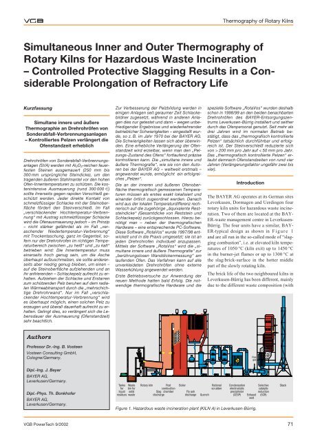
The BAYER AG operates at its German sites<br />
Leverkusen, Dormagen and Uerdingen four<br />
rotary kiln units for hazardous waste incineration.<br />
Two of them are located at the BAY-<br />
ER-waste management centre in Leverkusen-<br />
Bürrig. The four units have a similar, BAY-<br />
ER-typical design as shown in Figure 1<br />
and are all run in the so-called mode of “slagging<br />
combustion”, i.e. at elevated kiln temperatures<br />
of 1050 °C (kiln exit) up to 1450 °C<br />
in the burner-jet flames or up to 1300 °C at<br />
the slag/brick-surface in the hotter middle<br />
part of the slowly rotating kiln.<br />
The brick life of the two neighboured kilns in<br />
Leverkusen-Bürrig has been different, mainly<br />
due to the different waste composition (with<br />
Condensation<br />
electrostatic<br />
precipitator<br />
(CESP)<br />
Figure 1. Hazardous waste incineration plant (KILN A) in Leverkusen-Bürrig.<br />
VGB PowerTech 9/2002 71<br />
Flue<br />
gas<br />
Selective<br />
catalytic<br />
reduction<br />
Exhaust (SCR)<br />
vent<br />
Stack
Thermography of Rotary Kilns<br />
Thickness of residual brick<br />
(without frozen slag) in mm<br />
250<br />
200<br />
150<br />
Kiln operated without controlled slagging<br />
and without solid waste) and to the slightly<br />
different kiln capacities. The kilns had attained<br />
until 1997 a brick life of typically only<br />
6000 to 7000 hours in case of KILN A (combusting<br />
liquid, pasty and solid wastes) and<br />
20,000 hours in case of KILN B (combusting<br />
only liquid and pasty wastes).<br />
The main reason for this great difference in<br />
brick life is the solid waste feed and its often<br />
high content of “fixed carbon” [1, 2]. Carbon<br />
burn-out promotes reducing combustion conditions<br />
at the surface of the devolatized combustion-bed<br />
within the kiln. This reduces<br />
Fe2O3 (dissolved in the slag) to its lower<br />
melting form FeO, thus lowering the slag<br />
melting temperature considerably.<br />
As brick wear progresses, the brick thickness<br />
is diminishing from an original thickness of<br />
250 mm down to 40 to 50 mm as a minimum.<br />
Having reached this limit, the refractory lining<br />
must be renewed, totally or at least partially.<br />
A typical wear pattern is shown in Figure<br />
2 with the final axial profile of the<br />
“residual brick thickness” of KILN A (operated<br />
without controlled slagging) in November<br />
1997, after only 6000 hours.<br />
250<br />
150<br />
110<br />
80 75 65<br />
40<br />
100 110 125 100 120<br />
100<br />
50<br />
0<br />
1 2 3 4 5 6 7 8 9 10 11 12<br />
Distance x from rotary kiln entrance in m<br />
Figure 2. Residual brick thickness of KILN A after only<br />
6000 hours of uncontrolled operation (brick<br />
thickness only, measured by direct drilling<br />
after final shutdown in November 1997).<br />
In 1997 a BAYER-development<br />
project for “Prolonging Refractory<br />
Life” was initiated, aimed at extending<br />
the refractory life of both rotary<br />
kilns, which were in the meantime<br />
both fed with solid waste<br />
(unshredded in case of KILN A,<br />
shredded in case of KILN B).<br />
Slagging Combustion or Dry<br />
(Ashing) Combustion<br />
In case of “slagging combustion” the<br />
inner temperatures (approximately<br />
1100 to approximately 1400 °C) are<br />
considerably higher than in case of “dry (ashing)<br />
combustion” (approximately 800 to approximately<br />
1100 °C). But slagging combustion<br />
is not necessarily worse for brick life<br />
than dry (ashing) combustion. Under slagging<br />
combustion attained refractory life will be<br />
even longer than under dry (ashing) combustion,<br />
if the kiln-slagging is done properly,<br />
for example based on thermographical control<br />
as described here. Theoretically, brick wear<br />
might be eliminated completely in case of<br />
“slagging combustion”, if all brick heads and<br />
brick joints were permanently covered by a<br />
frozen slag layer, see Figure 3, showing<br />
still virgin bricks under the frozen slag-layer.<br />
Main points to achieve progress in daily industrial<br />
practice:<br />
— The formation and maintaining of a protective<br />
frozen slag-layer on top of all<br />
brick heads and brick joints necessitates<br />
dependable information about the kiln’s<br />
status (axial and peripheral profiles of the<br />
“equivalent brick thickness” as total sum<br />
of the thickness of residual brick and<br />
frozen slag), monitored online by “simultaneous<br />
inner and outer thermography”.<br />
— The maximal inner surface temperature,<br />
somewhere in the kiln’s hotter middle<br />
Virgin brick<br />
Frozen slag<br />
Liquefied slag<br />
Figure 3. “Virgin bricks“ under a protective frozen slag-layer.<br />
part, must be controlled (“inner thermography”)<br />
and minimized, for example by<br />
shifting the air distribution towards “less<br />
primary air/more secondary air”. (Outer<br />
means of temperature control as water<br />
spray cooling or enforced outer air cooling<br />
[4] were not applied here.)<br />
— Some basic know-how is needed about<br />
the slag’s melting-behaviour, as well with<br />
respect to its hemispherical melting-temperature<br />
and softening-temperature, as<br />
with respect to the so-called “width of the<br />
lower melting-point interval” (temperature<br />
difference between hemispherical<br />
melting-point and softening-point).<br />
— Further know-how and operational means<br />
must be available to alter the melting behaviour,<br />
by adding sand and/or other additives<br />
to the kiln feed.<br />
— Last but not least, highly liquefying sodium-rich<br />
compounds should be eliminated<br />
out of the solid waste feed as far as possible.<br />
“Controlled protective slagging” requires a<br />
balanced kiln operation between “too hot and<br />
too cold”. There are many aspects of a balanced<br />
kiln operation. Think for example<br />
about the necessary axial slag transport in<br />
case of slagging combustion. On the one<br />
hand, the inner surface temperatures must be<br />
maintained low enough to keep everywhere –<br />
directly on top of the refractory – a protective<br />
frozen slag-layer. On the other hand, the<br />
inner kiln surface temperatures must be<br />
maintained high enough to keep – on top of<br />
that frozen slag-layer – a sufficiently liquefied,<br />
mobile “viscous slag film”, slagging the<br />
kiln wall constantly under the influence of<br />
kiln rotation, and at the same time flowing<br />
axially towards the kiln exit.<br />
When a protective frozen slag layer is not<br />
achieved anymore, see Figure 4 showing<br />
exposed brick heads in the kiln’s hotter<br />
Slagfree<br />
brick heads<br />
Figure 4. Normal view back into KILN A (first exposed brick heads<br />
visible at the right hand side).<br />
72 VGB PowerTech 9/2002
middle part (right hand side), the kiln operator<br />
must start “slagging” the kiln’s wall.<br />
Thermographical Approach<br />
The described combined “simultaneous inner<br />
and outer thermography” as a new “non-contact<br />
wall thickness measurement” is, as far as<br />
is known to us, the first application worldwide<br />
in rotary kilns for hazardous waste incineration.<br />
Outer Temperature Measurements<br />
Outer thermographical temperature measurements<br />
are common practice in the cement industry,<br />
using so-called “line scanners”. This<br />
well-known measuring technique has been<br />
applied – since around 1989 – at some rotary<br />
kilns for hazardous waste incineration, too.<br />
Figure 5a shows an outer view at the<br />
KILN B (digital photo). As visible, the shell<br />
is partially obstructed.<br />
Figure 5b shows the corresponding outer<br />
temperature profiles (mean values as well as<br />
minimum and maximum values during one<br />
kiln rotation) as measured by a thermographical<br />
line scanner and evaluated by “RotaVos”.<br />
Inner Temperature Measurements<br />
Inner thermographical temperature measurements,<br />
using a so-called “firebox camera”,<br />
are applied in municipal solid waste incinerators<br />
for control of the burning zone location<br />
on the grates. Thermographical firebox<br />
cameras are also applied in other thermal<br />
processes (control of cement clinker cooling,<br />
of metal melting, of glass melting and glass<br />
cooling etc.).<br />
Figure 6a shows a thermographical image<br />
(BAYER-infrared-picture), made by the firebox<br />
camera M9200, looking backwards –<br />
through the post-combustion chamber – into<br />
KILN B; the thermocouple element at the<br />
kiln exit is visible even in this picture (high<br />
dissolution of the tested firebox camera).<br />
The firebox camera must apply “flame<br />
filters” to enable a clear view – through the<br />
kiln gas – directly at the slag/brick-surface,<br />
to measure the temperatures of the inner slag/<br />
brick-surface and not of the flame. Therefore,<br />
such a camera is working in a narrow wave<br />
length range of high “transmissivity of the<br />
combustion gases” (away from the CO2 and<br />
H2O radiation bands). For the same reason of<br />
visibility, dust forming wastes should be excluded<br />
from the waste feed during control<br />
measurements, minimizing gray radiation.<br />
Figure 6b shows three thermografically<br />
measured axial profiles of the inner slag surface<br />
temperature (along axial lines at the<br />
right hand, left hand and upper kiln side) in<br />
KILN A, evaluated by “RotaVos”. The lower<br />
horizontal line is indicating the<br />
gas temperature at the kiln exit, the<br />
so-called “kiln exit temperature”,<br />
given by the thermocouple element<br />
or measured thermographically<br />
along the thermocouple element’s<br />
outer surface. The thermographical<br />
temperature is almost identical<br />
(within ± 25 °C) with the thermocouple<br />
temperature itself.<br />
The excess-temperature in the<br />
kiln’s hotter middle part as marked<br />
in Figure 6b (200 °C = temperature<br />
difference between the maximal<br />
inner surface temperature and the<br />
Shell temperature in °C<br />
300<br />
250<br />
200<br />
150<br />
100<br />
50<br />
Blendings<br />
Thermography of Rotary Kilns<br />
Figure 5a. View at the outer shell of KILN B.<br />
Medium shell temperature Blending lines<br />
Max. shell temperature Environment temperature<br />
Min. shell temperature<br />
0<br />
0 1 2 3 4 5 6 7 8 9 10 11 12 13<br />
VGB PowerTech 9/2002 73<br />
Bearing ring 1<br />
Lantern post<br />
Gear ring hood<br />
Distance x from kiln entrance in m<br />
Figure 5b. Outer shell temperatures (mean values as well as minimum and maximum values<br />
during one kiln rotation) at KILN B.<br />
Figure 6a. Thermographical view back into KILN B with a PC-designed “cylindrical wire basket<br />
model of the inner kiln“ [<strong>Vosteen</strong>, 1998].<br />
Steel post<br />
Bearing ring 2<br />
Blending<br />
Blending
Thermography of Rotary Kilns<br />
Slag surface temperature<br />
in °C<br />
1500<br />
1400<br />
1300<br />
1200<br />
1100<br />
1000<br />
0 1 2 3 4 5 6 7 8 9 10 11 12 13<br />
Distance x from kiln entrance in m<br />
thermocouple temperature), has to be limited<br />
with respect to the slag’s melting behaviour,<br />
as will be discussed later.<br />
Evaluation of the Local<br />
Temperature Differences<br />
The evaluation of the local differences between<br />
the inner and outer temperatures is<br />
based on well-known laws of quasi stationary<br />
heat transfer, see Figure 7. The partial<br />
temperature difference (inner_slag_surface – outer_steel_shell_surface)<br />
as well as the total temperature<br />
difference (inner_slag_surface – environment)<br />
stand for the corresponding sums of heat<br />
transfer resistances. Therefore the thermographically<br />
measured ratio of these two<br />
temperature differences<br />
inner_slag_surface – outer_steel_shell_surface<br />
= –––––––––––––––––––––––––––––– (1)<br />
inner_slag_surface – environment<br />
can be interpreted as well as the ratio of the<br />
corresponding heat transfer resistances:<br />
Rslag_layer +Pbrick + Rair_gap + Rsteel_shell<br />
= –––––––––––––––––––––––––––––– (2)<br />
Rslag_layer +Rbrick +Rair_gap +<br />
+Rsteel_shell +Router_heat_transfer<br />
(x) as a function of the distance x from the<br />
kiln entrance gives a qualitative image of the<br />
axial wall thickness profile; see Figure 8<br />
as an example of KILN A, demonstrating<br />
KILN A<br />
Excess temperature<br />
Figure 6b. Inner axial temperature profiles in KILN A<br />
along different axial lines (at the right hand,<br />
left hand and upper kiln side).<br />
ψ<br />
1<br />
0.95<br />
0.9<br />
0.85<br />
0.8<br />
0.75<br />
0.7<br />
r<br />
ϑ Outer steel shell<br />
ϑEnvironment<br />
ϑ Slag surface<br />
heightened brick wear in the kiln’s hotter<br />
middle part, caused there by the highest local<br />
heat burden, see excess-temperature in Figure<br />
6b.<br />
1 - () as a function of the circumferential<br />
angle (= 0°... 360°) stands for the “open<br />
kiln width” in a chosen kiln cross section at<br />
x = constant, see Figure 9:<br />
The “elliptical shape” of the kiln’s “free<br />
cross section” at x = 2.02 m (Figure 9) is<br />
easily explained: In 1997 the brick lining had<br />
been made up of two different brick qualities<br />
– for testing reasons. The diagram shows that<br />
the brick quality I (installed right<br />
hand side, covering 60 % of the circumference)<br />
could not withstand<br />
the thermo-mechanical impact<br />
there, while the brick quality II (installed<br />
left hand side, covering 40 %<br />
of the circumference) was more<br />
stable. But already at x = 2.75 m<br />
both linings do not show significant<br />
differences in brick thickness anymore.<br />
The primarily thermographically<br />
measured resistance ratio , as well<br />
as the “free kiln- width” 1- depend<br />
on:<br />
ϑ<br />
Rfrozen slag layer<br />
Rfire resistant brick<br />
Rair gap brick/steel shell<br />
Rsteel shell<br />
Rheat transfer outside<br />
Figure 7. Sketch of the radial temperature profile ϑ(r) in<br />
the kiln wall and of the corresponding heat<br />
transport resistances Ri.<br />
0 1 2 3 4 5 6 7 8 9 10 11 12<br />
Distance x from kiln entrance in m<br />
Figure 8. Axial profile of the resistance ratio Ψ (x) in KILN A on August, 20, 1998.<br />
210 … 360 °<br />
brick quality I<br />
— the thickness sslag_layer<br />
of the frozen slaglayer<br />
and its thermal<br />
conductivity slag_layer<br />
— the thickness sbrick of<br />
the residual brick and<br />
its thermal conductivity<br />
brick,<br />
— the width sair_gap of an<br />
assumed (or in fact<br />
existing) air gap between<br />
the bricks and<br />
the inner steel shell<br />
surface and of its “effective<br />
thermal conductivity” (including<br />
thermal radiation),<br />
— the outer heat transfer coefficient outside.<br />
The thermal conductivities slag_layer and<br />
brick depend on the density (or porosity) and<br />
– with minor influence – on the local wall<br />
temperatures too. Examination of some slag<br />
lumps, removed from the kiln’s frozen slag<br />
layer (see Figure 3), revealed that the density<br />
of frozen slag (2.5 to 2.9 g/cm 3 ) and the density<br />
of refractory bricks are nearly the same.<br />
Therefore the thermal conductivities of brick<br />
and frozen slag should be the same, see Figure<br />
10.<br />
A requirement for the thermal calculations is<br />
the outer heat transfer coefficient (heat<br />
transfer from the outer shell to the environment).<br />
This heat transfer coefficient may be<br />
calculated classically, i. e. based on the<br />
known superposition of heat transfer by free<br />
convection and by thermal radiation, depending<br />
on the local temperature at the outer shell<br />
surface, see Figure 11.<br />
A further requirement is the (mean) width of<br />
the air gap between brick and inner steel<br />
shell. It must be mentioned that the assumed<br />
air gap may be a real physical parameter; or<br />
it is only an empirical “adaption factor”: The<br />
air gap width is playing an important role<br />
when bringing together exactly the thicknesses,<br />
online obtained thermographically,<br />
with those thicknesses, measured by slag/<br />
brick-drilling after shutdown of the kiln.<br />
x = 2.02 m<br />
x = 2.75 m<br />
74 VGB PowerTech 9/2002<br />
0 °<br />
270 °<br />
(1 – Ψ)<br />
0.18<br />
0.16<br />
m 0.14<br />
0.12<br />
0.10<br />
0.<strong>08</strong><br />
90 °<br />
180 °<br />
0 … 210 °<br />
brick quality II<br />
Figure 9. “Free kiln-width“ (1 - Ψ) – Peripheral profiles<br />
at x = 2.02 m and at x = 2.75 m distance from<br />
the entrance of KILN B on May, 28, 1998.
Thermal conductivity in W/(m 2 K)<br />
5<br />
4.5<br />
4<br />
3.5<br />
3<br />
2.5<br />
2<br />
1.5<br />
1<br />
0.5<br />
0<br />
Assumed<br />
conductivity<br />
of frozen slag<br />
0 0.5 1 1.5 2 2.5 3 3.5 4 4.5 5<br />
Density in g/cm 3<br />
Density of<br />
frozen slag<br />
Figure 10. Thermal conductivities of heavy and light<br />
refractory bricks at 700 … 800 °C and of air<br />
at 750 °C.<br />
Figure 12 shows the axial profile sslag+brick<br />
(x) as sum of both slag thickness and brick<br />
thickness, the so-called “equivalent brick<br />
thickness”.<br />
The thermographically obtained profiles of<br />
the “equivalent brick thickness” do agree<br />
very well – after primary adaptation of the<br />
(mean) air gap width – with those profiles,<br />
measured directly by drilling.<br />
Drilling must only be done from time to time,<br />
when a kiln has to be cooled down for other<br />
plant-maintenance reasons. Experience has<br />
shown that the air gap width may vary from<br />
kiln to kiln, but doesn’t change much at the<br />
same kiln during its brick life, with the exception<br />
of the first months of operation (brick<br />
settling).<br />
Melting Behaviour of Ashes and Slags<br />
Within the scope of this paper it is not possible<br />
to describe the melting behaviour of<br />
coal ashes (approximately 450 data sets) and<br />
hazardous waste slags (approximately 40 data<br />
sets) in full detail. An extensive report will<br />
be given later in a separate publication. Only<br />
some reference can be made:<br />
As mentioned above, low melting sodiumrich<br />
compounds should be eliminated out of<br />
the solid waste feed as far as possible. Under<br />
high temperature combustion, sodium-halogenides<br />
are rarely found in kiln exit slags,<br />
because they are volatized and transferred –<br />
via evaporation/sulphatation/desublimation –<br />
into the boiler fly ashes. Besides this, the<br />
melting behaviours of coal ashes and hazardous<br />
waste slags are strongly influenced by<br />
— the slag’s iron-content within the slag’s<br />
component-triplet “FeOn – SiO2 – Al2O3”<br />
(well understood as the mass fraction<br />
FeOn / (FeOn + SiO2 + Al2O3), expressed<br />
Total thickness of brick and slag<br />
in mm<br />
in weight-% with<br />
possible values ≥ 0 to<br />
≤ 100 % ) and by<br />
— the “oxidation state”<br />
of the iron oxide FeOn<br />
within the slag’s multicomponent<br />
mixture.<br />
Dissolved Fe2O3 (pure<br />
substance melting<br />
point: 1580 °C) may be<br />
reduced to FeO (pure<br />
substance melting<br />
point: 1390 °C), locally<br />
depending on the<br />
oxidizing or reducing<br />
kiln atmosphere.<br />
The diagrams in Figure<br />
13a (oxidizing conditions)<br />
and Figure 13b<br />
(reducing conditions),<br />
500<br />
400<br />
300<br />
200<br />
100<br />
Thermography of Rotary Kilns<br />
0<br />
0 100 200 300 400 500<br />
Outer shell temperature in °C<br />
VGB PowerTech 9/2002 75<br />
Outer heat transfer coefficient α<br />
W/(m2 K)<br />
70<br />
60<br />
50<br />
40<br />
30<br />
20<br />
10<br />
Total<br />
Thermal radiation<br />
(shell emissivity = 0.95)<br />
Free convection<br />
Figure 11. Outer heat transfer coefficient αoutside (upper<br />
line) by free convection and superimposed<br />
thermal radiation (shell emissivity ε = 0.95).<br />
Equivalent thickness of brick and slag<br />
(thermographical measurement April 28th, 1999)<br />
New brick lining in June 1998<br />
0<br />
0 1 2 3 4 5 6 7 8 9 10 11 12 13<br />
Distance x from kiln entrance in m<br />
Figure 12. Axial profile of the equivalent brick thickness sslag+brick (x) at KILN B, automatically<br />
calculated by „RotaVos“ on April, 28, 1999.<br />
HMP Melting point in °C<br />
under oxidizing conditions<br />
1600<br />
1500<br />
1400<br />
1300<br />
1200<br />
1100<br />
1000<br />
Lignite coal ashes<br />
Hard coal ashes<br />
Hazardous waste slags<br />
0<br />
0 10 20 30 40 50 60 70 80 90 100<br />
Fe 2 O 3 -content within the triplet in weight-%<br />
Figure 13a. Melting-point hammock under oxidizing combustion conditions (half-quantitative<br />
model, based on some 500 data sets, <strong>Vosteen</strong>, 1999).<br />
50<br />
100<br />
CaO-loading of the triplet<br />
in weight-%
Thermography of Rotary Kilns<br />
HMP Melting point in °C<br />
under reducing conditions<br />
1600<br />
1500<br />
1400<br />
1300<br />
1200<br />
1100<br />
1000<br />
0 10 20 30 40 50 60 70 80 90 100<br />
FeO-content within the triplet FeO + SiO 2 + Al 2 O 3<br />
in weight-%<br />
Figure 13b. Melting-point hammock under reducing combustion conditions (half-quantitative<br />
model, <strong>Vosteen</strong>, 1999).<br />
based on the compiled two data sets for coal<br />
ashes and slags, provide clarification to the<br />
known fact, that a perfect frozen slag-layer is<br />
melting away within a few hours, if the local<br />
Brick thickness<br />
(without slag) in mm<br />
250<br />
200<br />
150<br />
100<br />
50<br />
0<br />
1 2 3 4 5 6 7 8 9 10 11 12<br />
Distance x from kiln entrance in m<br />
7,700 operational hours (May 2000)<br />
14,464 operational hours (March 2001)<br />
18,316 operational hours (September 2001)<br />
Figure 14a. Three brick thickness profiles of KILN A<br />
(bricks only, thickness measured by direct drilling).<br />
500<br />
400<br />
300<br />
200<br />
100<br />
100<br />
0<br />
155 155<br />
100<br />
210<br />
150<br />
195<br />
250<br />
155<br />
300<br />
150<br />
300<br />
155<br />
300<br />
145<br />
350<br />
180<br />
350<br />
190<br />
350<br />
350 350<br />
220 250 250<br />
Thickness of residual brick<br />
and frozen slag in mm<br />
600<br />
KILN B – Total thickness of residual brick and frozen slag<br />
in August 2001 after 19,521 hours of kiln operation<br />
(measured by direct drilling)<br />
Kiln constantly operated with controlled slagging<br />
0<br />
1 2 3 4 5 6 7 8 9 10 11 12 13<br />
Distance x from rotary kiln entrance in m<br />
Figure 15a. Heavily slagged KILN B in August 2001 after 19,521 hours<br />
of controlled operation (thickness measured by direct<br />
drilling).<br />
0<br />
kiln atmosphere (at and in the burning kiln<br />
bed) is changed from oxidizing to reducing<br />
conditions. This change may happen, when<br />
for example activated carbon waste is added<br />
to the kiln’s feed, causing a reducing atmosphere<br />
at/in the combustion bed, and when nothing<br />
else is done to compensate for the resulting<br />
melting point depression.<br />
Another important aspect concerns the triplet’s<br />
so-called CaO-loading, i.e. the mass ratio<br />
CaO/(FeOn + Al2O3 + SiO2), and its influence<br />
on the slag’s “hemispherical melting<br />
point” itself, as well as on its “lower meltingpoint<br />
interval”, understood as the temperature<br />
difference between the slag’s hemispherical<br />
melting point and its softening point.<br />
The “lower melting-point interval” is a “material<br />
quality” of the slag’s component mixture.<br />
An increase of the CaO-loading first<br />
lowers the melting point and later heightens<br />
it. The kiln’s “excess-temperature” (see<br />
former Figure 6b), which is dependant on<br />
kiln operation, mainly on the air distribution,<br />
should not exceed the slag’s “lower meltingpoint<br />
interval”.<br />
A decisive increase of the CaO-loading by<br />
adding lime, as studied in [3] to minimize<br />
heavy metal slag-elution, will diminish the<br />
“lower melting-point interval” considerably.<br />
Any strong increase of the CaO-loading leads<br />
to a so-called “short slag”, making kiln slagging<br />
nearly impossible, because no kiln can<br />
76 VGB PowerTech 9/2002<br />
Brick thickness<br />
(without slag) in mm<br />
50<br />
250<br />
200<br />
150<br />
100<br />
50<br />
0<br />
100<br />
CaO-loading of the triplet<br />
in weight-%<br />
1 2 3 4 5 6 7 8 9 10 11 12 13<br />
Distance x from kiln entrance in m<br />
5,569 operational hours (October 1999)<br />
11,754 operational hours (June 2000)<br />
19,521 operational hours (August 2001)<br />
Figure 14b. Three brick thickness profiles of KILN B<br />
(bricks only, thickness measured by direct drilling).<br />
mm200<br />
Total thickness of residual brick<br />
and frozen slag in<br />
250<br />
0<br />
0<br />
150<br />
240<br />
100 180<br />
50<br />
0<br />
KILN A – Total thickness of residual brick and frozen slag<br />
in March 2001 after 14,464 hours of kiln operation<br />
(measured by direct drilling)<br />
15<br />
210<br />
15<br />
170<br />
Kiln constantly operated with controlled slagging<br />
15<br />
140<br />
15<br />
140<br />
1 2 3 4 5 6 7 8 9 10 11 12<br />
Distance x from rotary kiln entrance in m<br />
Figure 15b. Decently slagged KILN A in March 2001 after 14,464 hours<br />
of controlled operation (thickness measured by direct<br />
drilling).<br />
20<br />
140<br />
20<br />
140<br />
20<br />
150<br />
35<br />
155<br />
35<br />
160<br />
35<br />
180
e operated strictly isothermal. Therefore, the slag within the kiln<br />
would be either immobile (like “ice”) or highly mobile (like “water”),<br />
while “slagging” and “axial slag transport” necessitate both, a mobile<br />
slag film on top of an immobile frozen slag-layer.<br />
Industrial Results<br />
By “thermographically controlled slagging”, based on “simultaneous<br />
inner and outer thermography”, as described in this paper, the brick<br />
life of KILN A (formerly only 6000 to 7000 hours) was considerably<br />
increased, see Figure 14a, indicating that the brick life of this kiln –<br />
after almost 20,000 operational hours – has not yet come to its end. A<br />
new bricklining was installed after 21,776 operational hours in March<br />
2002.<br />
Figure 14b describes the corresponding results at the other KILN B<br />
(with formerly some 20,000 hours brick life), indicating that the application<br />
of “thermographically controlled slagging will prolong the<br />
brick life of this kiln up to possibly some 40,000 hours.<br />
Under actual waste management aspects, the applied method has an<br />
additional advantage: A thermographically-controlled kiln can be operated<br />
until a minimal residual brick thickness has been reached indeed.<br />
This advantage became obvious at the end of 1998, enabling a<br />
prolonged operation of KILN A until April 1999, giving five months<br />
time for maintenance works at other kilns.<br />
Final remarks: A kiln mustn’t always be slagged as heavily as shown<br />
in Figure 15a. But slagging only decently – as shown in Figure<br />
15b – might not be sufficient for brick protection.<br />
Summary and Conclusions<br />
It has been demonstrated that “thermographically-controlled slagging”<br />
can be successfully applied to the industrial operation of rotary kiln incinerators<br />
and that the developed new method, reducing brick wear to<br />
less than 50 mm/year, will prolong brick life considerably to 20,000 h<br />
and possibly far more. The applied method enables the plant operations<br />
manager to forecast the next required kiln shutdown more exactly,<br />
not requiring intermediate kiln shutdowns to verify brick thickness<br />
by drilling. The investment for the thermographical hardware has been<br />
returned – by reduction of brick wear at two neighboured kilns – within<br />
less than six months.<br />
The authors would like to thank all colleagues and plant personnel involved<br />
in the described developmental work and its industrial application.<br />
Special thanks to Dipl.-Ing. Franz-Josef Johann (final diploma<br />
thesis on “Thermography”), to Dipl.-Ing. Marcus Simon (final diploma<br />
thesis on “Melting Behaviour and Kiln Slagging”) as students with<br />
Professor <strong>Vosteen</strong> and to Dipl.-Ing. Maria Fayos-Galan as post graduate<br />
student for valuable contributions, and finally to Dr. Klaus Hagemeyer,<br />
re-designing the software “RotaVos” for commercial use.<br />
References<br />
[1] <strong>Vosteen</strong>, B., and Beyer, J.: Obtainable Residual Carbon Content in Slags<br />
and Ashes from Waste Incineration Systems. Part I: Fixed Carbon as a<br />
Waste Property and Fixed Carbon Burn-Up in Different Waste Incinerators.<br />
VGB PowerTech 80 (2000), No. 9, pp. 48 – 52.<br />
[2] <strong>Vosteen</strong>, B., and Beyer, J.: Obtainable Residual Carbon Content in Slags<br />
and Ashes from Waste Incineration Systems. Part II: Loss on Ignition and<br />
Residual Carbon in Ashes from Municipal Solid Waste Incinerator Plants<br />
(MSWIP) and in Slags from Hazardous Waste Incinerator Plants (HWIP).<br />
VGB PowerTech 80 (2000), No. 10, pp. 74 – 75.<br />
[3] Reich, J.: Optimierung des Eluationsverhaltens von Aschen aus der<br />
Sonderabfallverbrennung. Dissertation Gerhard-Mercator-Universität –<br />
Gesamthochschule Duisburg, March 12, 2001.<br />
[4] R. Ullrich, WastePro Engineering Inc., PA (USA): Personal note to the<br />
authors in 2001 about an application of outer cooling fans, combined with<br />
the addition of sand and recycled slag.<br />
VGB PowerTech 9/2002 77