A GPU-Based Approach to Non-Photorealistic Rendering in the ...
A GPU-Based Approach to Non-Photorealistic Rendering in the ...
A GPU-Based Approach to Non-Photorealistic Rendering in the ...

Create successful ePaper yourself
Turn your PDF publications into a flip-book with our unique Google optimized e-Paper software.
esult was so stylized, no orientation of graftals would be<br />
necessary. Unfortunately, this was not <strong>the</strong> case.<br />
Close exam<strong>in</strong>ation of Mignola’s work showed that <strong>the</strong><br />
small marks used for surface details were not at all randomly<br />
oriented or distributed – while lack<strong>in</strong>g depth, <strong>the</strong>y all<br />
followed <strong>the</strong> 2D orientation of <strong>the</strong> surface <strong>the</strong>y were placed<br />
along. This is most easily seen <strong>in</strong> Figure 4. The scale<br />
“graftals” placed along <strong>the</strong> tail of <strong>the</strong> mermaid are oriented <strong>in</strong><br />
2D <strong>to</strong> match <strong>the</strong> curve of <strong>the</strong> tail. This orientation means<br />
graftals must be generated based on surface geometry.<br />
We <strong>the</strong>n attempted <strong>to</strong> use an approach more directly<br />
related that that outl<strong>in</strong>ed by Hertzmann and Zor<strong>in</strong>. We tried<br />
generat<strong>in</strong>g graftals at edges, parallel <strong>to</strong> <strong>the</strong> screen but with<br />
one edge set <strong>to</strong> an edge on <strong>the</strong> mesh. Unfortunately, <strong>the</strong><br />
orientation <strong>to</strong> <strong>the</strong> screen made self-<strong>in</strong>tersection a significant<br />
problem. Without any time-consum<strong>in</strong>g self-<strong>in</strong>tersection<br />
prevention, <strong>the</strong>re was no way <strong>to</strong> guarantee surface details<br />
wouldn’t disappear <strong>in</strong><strong>to</strong> geometry – especially with randomly<br />
placed graftals.<br />
Due <strong>to</strong> scope and time constra<strong>in</strong>ts, we were unable <strong>to</strong><br />
attempt o<strong>the</strong>r solutions.<br />
3.4. Shadow Outl<strong>in</strong><strong>in</strong>g<br />
As with surface graftals, shadow outl<strong>in</strong><strong>in</strong>g proved more<br />
difficult than orig<strong>in</strong>ally expected.<br />
Orig<strong>in</strong>ally, we had <strong>in</strong>tended <strong>to</strong> use edge-aligned<br />
graftals, as described above, <strong>to</strong> provide variation along<br />
shadow edges. The self-<strong>in</strong>tersection problems of surfaceoriented<br />
graftals, however, were also a problem with<br />
shadow-bound<strong>in</strong>g graftals.<br />
We moved on <strong>to</strong> attempt <strong>to</strong> use textured strokes <strong>to</strong><br />
def<strong>in</strong>e edges. While self-<strong>in</strong>tersection was still an issue, it was<br />
more manageable with controlled stroke-width.<br />
To determ<strong>in</strong>e if an edge was shadow-bound<strong>in</strong>g, we<br />
simply used <strong>the</strong> same dot product used <strong>in</strong> <strong>the</strong> render<strong>in</strong>g<br />
equation <strong>to</strong> calculate light <strong>in</strong>tensity at a po<strong>in</strong>t. As with <strong>the</strong><br />
<strong>in</strong>tensity clamp<strong>in</strong>g used for <strong>the</strong> shad<strong>in</strong>g, we used α as a<br />
cu<strong>to</strong>ff. If <strong>the</strong> <strong>in</strong>tensity on one edge-connected face was<br />
greater than α and <strong>the</strong> <strong>in</strong>tensity on <strong>the</strong> o<strong>the</strong>r was not, that<br />
edge was a shadow-bound<strong>in</strong>g edge. Intensity was calculated<br />
us<strong>in</strong>g <strong>the</strong> usual formula:<br />
Intensity = dot(light direction, face normal)<br />
The problems arose with actually f<strong>in</strong>d<strong>in</strong>g a shadowbound<strong>in</strong>g<br />
edge. With an outl<strong>in</strong>ed edge, <strong>the</strong>re is no<br />
<strong>in</strong>terpolation between po<strong>in</strong>ts – that is, <strong>the</strong> outl<strong>in</strong>e will always<br />
be made of discrete, straight l<strong>in</strong>e segments. But with shad<strong>in</strong>g,<br />
<strong>the</strong>re is <strong>in</strong>terpolation between vertices, and even texture<br />
lookups <strong>to</strong> modify <strong>the</strong> vertex normal if normal mapp<strong>in</strong>g is<br />
used. All of this additional normal <strong>in</strong>formation is only<br />
accessible <strong>to</strong> <strong>the</strong> fragment shader. S<strong>in</strong>ce we did all<br />
implementation of <strong>the</strong> stroke-generation on <strong>the</strong> vertex<br />
shader, <strong>the</strong>re was no way <strong>to</strong> get shadow-boundaries smoo<strong>the</strong>r<br />
than <strong>the</strong> edges of <strong>the</strong> triangulated mesh. In some cases,<br />
depend<strong>in</strong>g on triangulation, this led <strong>to</strong> a zigzagg<strong>in</strong>g stroke<br />
down <strong>the</strong> front of <strong>the</strong> mesh, which did not actually follow <strong>the</strong><br />
shad<strong>in</strong>g.<br />
Without any sort of <strong>in</strong>terpolation across triangles, <strong>the</strong>re<br />
was no way <strong>to</strong> avoid this jaggedness.<br />
4. Results<br />
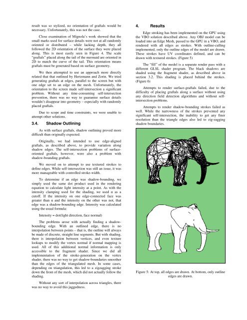
Edge strok<strong>in</strong>g has been implemented on <strong>the</strong> <strong>GPU</strong> us<strong>in</strong>g<br />
<strong>the</strong> VBO solution described above. Any OBJ model can be<br />
loaded <strong>in</strong><strong>to</strong> an Edge Mesh, passed <strong>to</strong> <strong>the</strong> <strong>GPU</strong> <strong>in</strong> a VBO, and<br />
rendered with all edges as strokes. With outl<strong>in</strong>e-cull<strong>in</strong>g<br />
implemented, only <strong>the</strong> outl<strong>in</strong>e edges of <strong>the</strong> model are drawn.<br />
These strokes have UV coord<strong>in</strong>ates def<strong>in</strong>ed, and can be<br />
drawn with textured strokes. (Figure 5)<br />
The “fill” of <strong>the</strong> model is a separate render pass with a<br />
different GLSL shader program. The black shadows are<br />
shaded us<strong>in</strong>g <strong>the</strong> fragment shader, as described above <strong>in</strong><br />
section 3.2. This shad<strong>in</strong>g is placed beh<strong>in</strong>d <strong>the</strong> strokes.<br />
(Figure 6)<br />
Attempts <strong>to</strong> render surface-graftals failed, due <strong>to</strong> <strong>the</strong><br />
difficulty of plac<strong>in</strong>g graftals along a surface without us<strong>in</strong>g<br />
any direction field detection algorithms and without self<strong>in</strong>tersection<br />
problems.<br />
Attempts <strong>to</strong> render shadow-bound<strong>in</strong>g strokes failed as<br />
well. While <strong>the</strong> narrowness of <strong>the</strong> strokes prevented any<br />
significant self-<strong>in</strong>tersection, <strong>the</strong> <strong>in</strong>ability <strong>to</strong> get any f<strong>in</strong>er<br />
resolution than <strong>the</strong> triangle edges also led <strong>to</strong> zig-zagg<strong>in</strong>g<br />
shadow boundaries.<br />
Figure 5: At <strong>to</strong>p, all edges are drawn. At bot<strong>to</strong>m, only outl<strong>in</strong>e<br />
edges are drawn.