A GPU-Based Approach to Non-Photorealistic Rendering in the ...
A GPU-Based Approach to Non-Photorealistic Rendering in the ...
A GPU-Based Approach to Non-Photorealistic Rendering in the ...

Create successful ePaper yourself
Turn your PDF publications into a flip-book with our unique Google optimized e-Paper software.
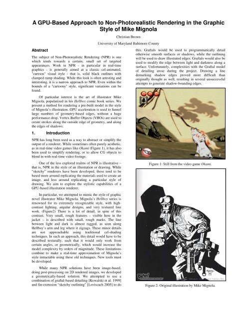
A <strong>GPU</strong>-<strong>Based</strong> <strong>Approach</strong> <strong>to</strong> <strong>Non</strong>-Pho<strong>to</strong>realistic <strong>Render<strong>in</strong>g</strong> <strong>in</strong> <strong>the</strong> Graphic<br />
Style of Mike Mignola<br />
Abstract<br />
The subject of <strong>Non</strong>-Pho<strong>to</strong>realistic <strong>Render<strong>in</strong>g</strong> (NPR) is one<br />
which tends <strong>to</strong>wards a certa<strong>in</strong>, small set of targeted<br />
appearances. Work <strong>in</strong> NPR - <strong>in</strong> particular <strong>in</strong> real-time<br />
graphics - is generally aimed at a classic cel-animated,<br />
"car<strong>to</strong>on" visual style - that is, solid black outl<strong>in</strong>es with<br />
clamped ramp shad<strong>in</strong>g. While this look is often arrest<strong>in</strong>g and<br />
<strong>in</strong>terest<strong>in</strong>g, it is a narrow approach <strong>to</strong> NPR. Even with<strong>in</strong> <strong>the</strong><br />
bounds of a "car<strong>to</strong>ony" style, significant variations can be<br />
found.<br />
Of particular <strong>in</strong>terest is <strong>the</strong> art of illustra<strong>to</strong>r Mike<br />
Mignola, popularized <strong>in</strong> his Hellboy comic book series. We<br />
present a method for render<strong>in</strong>g a pre-built model <strong>in</strong> <strong>the</strong> style<br />
of Mignola’s illustration. <strong>GPU</strong> acceleration is used <strong>to</strong> funnel<br />
large numbers of geometry-based edges, without a huge<br />
performance drop. Vertex Buffer Objects (VBOs) are used <strong>to</strong><br />
create strokes along <strong>the</strong> outside edge of geometry, and along<br />
<strong>the</strong> edges of shadows.<br />
1. Introduction<br />
NPR has long been used as a way <strong>to</strong> abstract or simplify <strong>the</strong><br />
output of a renderer. While sometimes often purely aes<strong>the</strong>tic,<br />
as <strong>in</strong> real-time video games like Okami (Figure 1), it has also<br />
been used <strong>to</strong> simplify render<strong>in</strong>g, or <strong>to</strong> allow CG objects <strong>to</strong><br />
blend <strong>in</strong> with real-time video footage.<br />
One of <strong>the</strong> less explored realms of NPR is illustrative –<br />
that is, NPR <strong>in</strong> <strong>the</strong> style of an illustration or draw<strong>in</strong>g. While<br />
“sketchy” renderers have been developed, <strong>the</strong>se tend <strong>to</strong> be<br />
based more around replicat<strong>in</strong>g <strong>the</strong> materials used <strong>to</strong> create an<br />
image, and less around replicat<strong>in</strong>g a particular style of<br />
draw<strong>in</strong>g. We aim <strong>to</strong> explore <strong>the</strong> stylistic capabilities of a<br />
<strong>GPU</strong>-based illustration renderer.<br />
In particular, we attempted <strong>to</strong> mimic <strong>the</strong> style of graphic<br />
novel illustra<strong>to</strong>r Mike Mignola. Mignola’s Hellboy series is<br />
renowned for its extremely recognizable style, with highcontrast<br />
light<strong>in</strong>g, angular designs, and very textured l<strong>in</strong>e<br />
work. (Figure2) There is a lot of detail, <strong>in</strong> spite of this<br />
contrast. Very small, rough features – visible here <strong>in</strong> <strong>the</strong><br />
jacket – is described with small, rough marks. The l<strong>in</strong>e<br />
between light and dark is almost ragged, as seen along<br />
Hellboy’s arm and leg where it zigzags. These m<strong>in</strong>or details<br />
are not approachable us<strong>in</strong>g traditional cel-shad<strong>in</strong>g<br />
techniques. In such an approach, this detail would have <strong>to</strong> be<br />
described texturally, such that it would only work from<br />
certa<strong>in</strong> angles, or geometrically, which would <strong>in</strong>crease <strong>the</strong><br />
model complexity by orders of magnitude. These limitations<br />
comb<strong>in</strong>e <strong>to</strong> make a real-time approximation of Mignola’s<br />
style <strong>in</strong>tractable us<strong>in</strong>g <strong>the</strong>se old techniques. New <strong>to</strong>ols must<br />
be developed.<br />
While many NPR solutions have been image-based,<br />
do<strong>in</strong>g post-process<strong>in</strong>g on 2D rendered images, we developed<br />
a geometrically-based solution. We attempted <strong>to</strong> use a<br />
comb<strong>in</strong>ation of graftal-based detail<strong>in</strong>g [Kowalski et al. 1999]<br />
and f<strong>in</strong>-extrusion “sketchy outl<strong>in</strong><strong>in</strong>g” [Loviscach 2005] <strong>to</strong> do<br />
Christian Brown<br />
University of Maryland Baltimore County<br />
this. Graftals would be used <strong>to</strong> programmatically detail<br />
o<strong>the</strong>rwise smooth surfaces or shadows, while <strong>the</strong> outl<strong>in</strong><strong>in</strong>g<br />
will be used <strong>to</strong> draw illustrated edges. Graftals would also be<br />
used <strong>to</strong> modify <strong>the</strong> edge between light and darkness along a<br />
surface. Unfortunately, complexities with <strong>the</strong> Graftal model<br />
of detail<strong>in</strong>g arose dur<strong>in</strong>g <strong>the</strong> project. Draw<strong>in</strong>g a l<strong>in</strong>e<br />
demark<strong>in</strong>g shadow edges proved more difficult than<br />
orig<strong>in</strong>ally thought as well, result<strong>in</strong>g <strong>in</strong> several unsuccessful<br />
attempts <strong>to</strong> generate shadow-bound<strong>in</strong>g edges.<br />
Figure 1: Still from <strong>the</strong> video game Okami.<br />
Figure 2: Orig<strong>in</strong>al illustration by Mike Mignola.
2. Related Work<br />
Hertzmann and Zor<strong>in</strong> [2000] were <strong>in</strong>terested <strong>in</strong> simulat<strong>in</strong>g<br />
artistic shad<strong>in</strong>g and hatch<strong>in</strong>g <strong>in</strong> rendered images. In<br />
“Illustrat<strong>in</strong>g Smooth Surfaces,” <strong>the</strong>y analyzed both <strong>the</strong><br />
technical and stylistic approaches <strong>to</strong> shad<strong>in</strong>g used by artists –<br />
<strong>in</strong> particular, by l<strong>in</strong>e-artists who created engrav<strong>in</strong>gs or<br />
woodcuts. By analyz<strong>in</strong>g <strong>the</strong>se pre-exist<strong>in</strong>g images,<br />
Hertzmann and Zor<strong>in</strong> were able <strong>to</strong> develop new approaches<br />
<strong>to</strong> shad<strong>in</strong>g, and development methods which, while not<br />
strictly realistic, made it much easier for viewers <strong>to</strong> <strong>in</strong>terpret<br />
complex images. They determ<strong>in</strong>ed that hatch curvature was<br />
less useful for describ<strong>in</strong>g small details, but <strong>in</strong>stead developed<br />
techniques <strong>to</strong> overlay different directions of straight hatch<strong>in</strong>g<br />
<strong>to</strong> describe chang<strong>in</strong>g or curv<strong>in</strong>g surfaces. They also<br />
developed “Mach bands” and undercuts, techniques <strong>to</strong><br />
enhance <strong>the</strong> contrast between overlapp<strong>in</strong>g but similarly lit<br />
areas on <strong>the</strong> same surface.<br />
All of <strong>the</strong>se techniques represent stylistic achievements.<br />
They take advantage of optical illusions or confusion of <strong>the</strong><br />
viewer’s eye <strong>to</strong> simulate o<strong>the</strong>rwise complex images.<br />
Likewise, <strong>the</strong> use of non-realistic light<strong>in</strong>g techniques by<br />
Gooch et al. [1998] allowed for a far greater apparent<br />
dynamic range than a realistic light<strong>in</strong>g model would have.<br />
This research comb<strong>in</strong>es <strong>to</strong> describe many situations <strong>in</strong><br />
which stylization is not only aes<strong>the</strong>tically pleas<strong>in</strong>g, but also<br />
conveys useful <strong>in</strong>formation. By study<strong>in</strong>g artists ra<strong>the</strong>r than<br />
physics, <strong>the</strong>se researchers found novel ways <strong>to</strong> render<br />
o<strong>the</strong>rwise complicated subjects.<br />
Several papers have described <strong>in</strong>teractive methods of<br />
generat<strong>in</strong>g artistic renders. Salisbury et al. [1997] developed<br />
a technique for us<strong>in</strong>g a vec<strong>to</strong>r field and a vec<strong>to</strong>r-based<br />
collection of brush strokes <strong>to</strong> generate images that appeared<br />
hand-drawn. Their use of vec<strong>to</strong>r fields, albeit ones generated<br />
by an artist, were a precursor <strong>to</strong> <strong>the</strong> direction fields of<br />
Hertzmann and Zor<strong>in</strong> [2000]. The process of creat<strong>in</strong>g an<br />
image us<strong>in</strong>g this technique relied on hav<strong>in</strong>g an artist place<br />
vec<strong>to</strong>rs along an image, and “color code” <strong>the</strong> image based on<br />
which stroke would be used <strong>to</strong> draw it <strong>in</strong>.<br />
Kaln<strong>in</strong>s et al. [2002] cont<strong>in</strong>ued with <strong>the</strong> <strong>in</strong>teractive<br />
approach, but shifted from plac<strong>in</strong>g brush strokes on an image<br />
<strong>to</strong> plac<strong>in</strong>g <strong>the</strong>m on a 3D model. While not real-time, <strong>the</strong><br />
comb<strong>in</strong>ation of a surface shader and a light<strong>in</strong>g model<br />
provided a complete package for controll<strong>in</strong>g <strong>the</strong> artistic<br />
appearance of an NPR system.<br />
With <strong>the</strong> development of <strong>GPU</strong>-based render<strong>in</strong>g,<br />
complex variants on traditional render<strong>in</strong>g techniques were<br />
developed. McGuire and Hughes [2004] described a<br />
technique <strong>to</strong> use <strong>the</strong> <strong>GPU</strong> <strong>to</strong> determ<strong>in</strong>e edge-features and<br />
outl<strong>in</strong>es, render<strong>in</strong>g <strong>the</strong>m entirely us<strong>in</strong>g Vertex Buffer<br />
Objects. Loviscach’s “Stylized Haloed Outl<strong>in</strong>es on <strong>the</strong> <strong>GPU</strong>”<br />
[2005] described a VBO-based <strong>GPU</strong> render<strong>in</strong>g technique for<br />
outl<strong>in</strong>ed edges that also uses multiple passes and imagebased<br />
jitter<strong>in</strong>g <strong>to</strong> create a very sketchy appearance. (Figure<br />
3)<br />
F<strong>in</strong>ally, Kowalski et al. [1999] described a technique <strong>to</strong><br />
approximate o<strong>the</strong>rwise complicated appearances by styliz<strong>in</strong>g<br />
and abstract<strong>in</strong>g <strong>the</strong>m us<strong>in</strong>g “graftals”. These graftals are<br />
small, easily modified pieces which can be used <strong>to</strong> draw fur,<br />
tufts, or o<strong>the</strong>r surface detail on an o<strong>the</strong>rwise simple model.<br />
Figure 3: Haloed sketchy outl<strong>in</strong>es. [Loviscach, 2005]<br />
3. Implementation<br />
We attempted <strong>to</strong> use four techniques <strong>to</strong> approximate<br />
Mignola’s artistic style.<br />
First, we outl<strong>in</strong>ed <strong>the</strong> models us<strong>in</strong>g <strong>the</strong> f<strong>in</strong>n<strong>in</strong>g<br />
technique described by McGuire and Hughes [2004].<br />
Second, we used high-contrast light<strong>in</strong>g <strong>to</strong> give <strong>the</strong> same<br />
<strong>in</strong>ky shadows Mignola uses. This was done on <strong>the</strong> <strong>GPU</strong>,<br />
us<strong>in</strong>g a vertex shader. We attempted <strong>to</strong> use a texture <strong>to</strong><br />
provide <strong>the</strong> impression of draw<strong>in</strong>g <strong>in</strong> <strong>the</strong> fills with a marker,<br />
but were unable <strong>to</strong> orient <strong>the</strong> textures properly without more<br />
<strong>in</strong>formation on <strong>the</strong> <strong>GPU</strong>.<br />
Third, we attempted <strong>to</strong> use graftals <strong>to</strong> simulate<br />
o<strong>the</strong>rwise <strong>in</strong>visible surface detail – pock marks, bumps, etc.<br />
These were <strong>in</strong>tended <strong>to</strong> be def<strong>in</strong>ed ahead of time, and will be<br />
present both <strong>in</strong> shaded and lit areas. They will particularly be<br />
used <strong>to</strong> def<strong>in</strong>e texture <strong>in</strong> large, well-lit areas.<br />
Fourth, we attempted <strong>to</strong> use several techniques – most<br />
notably graftals and textured outl<strong>in</strong>es – <strong>to</strong> create complex<br />
divisions between lit and shaded areas. The “zigzagg<strong>in</strong>g”<br />
shadows seen <strong>in</strong> Figure 2, as well as o<strong>the</strong>r shad<strong>in</strong>g<br />
techniques, were explored.<br />
These techniques were applied <strong>to</strong> black and white<br />
images, mimick<strong>in</strong>g <strong>the</strong> look of an un-<strong>in</strong>ked illustration by<br />
Mignola.<br />
3.1. Outl<strong>in</strong><strong>in</strong>g<br />
Outl<strong>in</strong><strong>in</strong>g was executed us<strong>in</strong>g <strong>the</strong> Vertex Buffer Object based<br />
<strong>GPU</strong>-accelerated technique described by McGuire et al.<br />
[2004]. The model file is read <strong>in</strong><strong>to</strong> an Edge Mesh, <strong>in</strong> which<br />
<strong>in</strong>formation about an edge <strong>in</strong> <strong>the</strong> model is encoded <strong>in</strong><strong>to</strong><br />
vertex position, color, and multitexture <strong>in</strong>formation.<br />
In order <strong>to</strong> determ<strong>in</strong>e whe<strong>the</strong>r an edge <strong>in</strong> a mesh is an<br />
outl<strong>in</strong>e edge, <strong>the</strong> normal vec<strong>to</strong>rs of <strong>the</strong> two fac<strong>in</strong>g faces must<br />
be compared. If one face normal faces <strong>the</strong> camera and <strong>the</strong><br />
o<strong>the</strong>r does not, <strong>the</strong> edge between <strong>the</strong>m is an outl<strong>in</strong>e edge.<br />
While this technique only works with faces that are<br />
guaranteed <strong>to</strong> be coplanar, this <strong>in</strong>cludes any triangular mesh.<br />
We tested this technique on several OBJ files with success.<br />
The relevant <strong>in</strong>formation can be encoded <strong>in</strong> several<br />
ways. While Loviscach encoded <strong>the</strong> <strong>in</strong>formation <strong>in</strong> <strong>to</strong> several<br />
float<strong>in</strong>g-po<strong>in</strong>t values, ra<strong>the</strong>r than us<strong>in</strong>g <strong>the</strong> full 6-value<br />
method, this was not useful for our method. The four-value
technique only worked when only edge-outl<strong>in</strong>es were be<strong>in</strong>g<br />
drawn. S<strong>in</strong>ce we were attempt<strong>in</strong>g <strong>to</strong> draw non-outl<strong>in</strong>e edges<br />
along shadow boundaries, we had <strong>to</strong> <strong>in</strong>clude all 6 vec<strong>to</strong>r<br />
values.<br />
These 6 values are called v0, v1, v2, v3, n1, and n2.<br />
Each edge <strong>in</strong> <strong>the</strong> mesh must be described us<strong>in</strong>g all 6 of <strong>the</strong>se<br />
values <strong>in</strong> <strong>the</strong> Edge Mesh. v0 and v1 are <strong>the</strong> positions of <strong>the</strong><br />
endpo<strong>in</strong>ts of an edge, v2 is a third po<strong>in</strong>t on one face that uses<br />
<strong>the</strong> edge, and v3 is <strong>the</strong> position of <strong>the</strong> third po<strong>in</strong>t on <strong>the</strong> o<strong>the</strong>r<br />
face. n0 and n1 are <strong>the</strong> normal vec<strong>to</strong>rs of v0 and v1,<br />
respectively. The face normals of each of <strong>the</strong> faces shar<strong>in</strong>g<br />
<strong>the</strong> edge, nA and nB, can be calculated us<strong>in</strong>g v0-4 and n0-1.<br />
(Figure 4)<br />
Figure 4: v0, v1, v2, v3, def<strong>in</strong>e <strong>the</strong> relevant vertices, while<br />
n0 and n1 def<strong>in</strong>e <strong>the</strong> relevant normals. nA and nB can be<br />
calculated <strong>in</strong> <strong>the</strong> vertex shader us<strong>in</strong>g cross products.<br />
[McGuire and Hughes, 2004]<br />
S<strong>in</strong>ce OBJs are described by <strong>in</strong>dexed vertices and faces,<br />
we must iterate across <strong>the</strong> faces and s<strong>to</strong>re <strong>the</strong> implicitly<br />
def<strong>in</strong>ed edges. Each edge will be def<strong>in</strong>ed twice (once by each<br />
face which shares it), so we must protect aga<strong>in</strong>st edge<br />
duplication. Once <strong>the</strong> edges are extracted, we can def<strong>in</strong>e <strong>the</strong><br />
Edge Mesh.<br />
S<strong>in</strong>ce we used VBOs <strong>to</strong> pass edge <strong>in</strong>formation <strong>to</strong> <strong>the</strong><br />
vertex program, we must encode edge <strong>in</strong>formation <strong>in</strong><strong>to</strong> a<br />
s<strong>in</strong>gle vertex structure.<br />
When us<strong>in</strong>g VBOs, each vertex is described us<strong>in</strong>g an<br />
array of floats – one array for each attribute of <strong>the</strong> vertex<br />
be<strong>in</strong>g described. We used <strong>the</strong>se attributes <strong>to</strong> encode edge<br />
<strong>in</strong>formation – specifically, <strong>the</strong> MultiTexCoord attributes. We<br />
encoded v0 and v1 <strong>in</strong><strong>to</strong> <strong>the</strong> Position and Color attributes, and<br />
<strong>the</strong> rema<strong>in</strong><strong>in</strong>g attributes <strong>in</strong><strong>to</strong> MultiTexCoord0-3. We called<br />
this collection of edge-describ<strong>in</strong>g attributes packed <strong>in</strong><strong>to</strong> a<br />
s<strong>in</strong>gle vertex object an “Edge Vertex Object.”<br />
Us<strong>in</strong>g only a vertex shader and a fragment shader, we<br />
cannot create additional geometry on hardware. Thus, while<br />
each Edge Vertex Object conta<strong>in</strong>s all necessary <strong>in</strong>formation<br />
<strong>to</strong> create an edge quad, <strong>the</strong> edge shader can only do this if it<br />
receives for “vertices” that it can transform <strong>in</strong><strong>to</strong> <strong>the</strong> corners<br />
of <strong>the</strong> quad. This means each Edge Vertex Object (EVO)<br />
must be duplicated four times – one for each corner.<br />
In order <strong>to</strong> make sure each EVO is transformed <strong>to</strong> <strong>the</strong><br />
correct corner, we must <strong>in</strong>clude an <strong>in</strong>dex<strong>in</strong>g value. The first<br />
corner is <strong>in</strong>dex 0, <strong>the</strong> second corner is <strong>in</strong>dex 1, etc. This<br />
fourth value must be passed us<strong>in</strong>g an additional<br />
MultiTexCoord attribute.<br />
The vertex shader uses <strong>the</strong>se attributes <strong>to</strong> transform <strong>the</strong><br />
vertices <strong>to</strong> <strong>the</strong> appropriate positions. To do this, use <strong>the</strong><br />
follow<strong>in</strong>g vec<strong>to</strong>rs and values for <strong>the</strong>m:<br />
s0 = (MVP * v0).xy<br />
s1 = (MVP * v1).xy<br />
p = normalize( )<br />
s0 and s1 are <strong>the</strong> screen-space endpo<strong>in</strong>ts for <strong>the</strong> edge,<br />
and p is a normalized vec<strong>to</strong>r perpendicular <strong>to</strong> s0 and s1. This<br />
means <strong>the</strong> f<strong>in</strong>al position on one vertex <strong>in</strong> <strong>the</strong> vertex shader is:<br />
Position = s0 + p if i = 0<br />
s1 + p if i = 1<br />
s1 - p if i = 2<br />
s0 - p if i = 3<br />
If <strong>the</strong> edge is not an outl<strong>in</strong>e, its position is transformed<br />
<strong>to</strong> beh<strong>in</strong>d <strong>the</strong> clipp<strong>in</strong>g plane. This also culls it from <strong>the</strong><br />
fragment shader, preempt<strong>in</strong>g <strong>the</strong> need for any additional<br />
cull<strong>in</strong>g.<br />
Stroke <strong>in</strong>formation and appearance can be passed as a<br />
texture, and applied <strong>to</strong> <strong>the</strong> strokes. This can be used for a few<br />
purposes. Most obviously, and as used previously, it can be<br />
used <strong>to</strong> def<strong>in</strong>e a stylized stroke appearance.<br />
3.2. Shad<strong>in</strong>g<br />
On close exam<strong>in</strong>ation, <strong>in</strong> all but straight black-and-white<br />
outl<strong>in</strong>e illustration, Mignola’s draw<strong>in</strong>gs have subtle gradients<br />
found <strong>in</strong> <strong>the</strong>m. These gradients add a little depth <strong>to</strong> even <strong>the</strong><br />
well-lit areas of <strong>the</strong> draw<strong>in</strong>g. While <strong>in</strong> Mignola’s illustration,<br />
<strong>the</strong>se are often abstracted and simplified gradients, such<br />
simplification is outside <strong>the</strong> scope of this paper. To simulate<br />
<strong>the</strong> subtle shad<strong>in</strong>g, we simply implemented a clamped and<br />
modified shad<strong>in</strong>g algorithm.<br />
For <strong>the</strong> large “pools of shadows” that cover <strong>the</strong> models,<br />
we simply moni<strong>to</strong>red <strong>the</strong> <strong>in</strong>tensity of light <strong>in</strong> <strong>the</strong> fragment<br />
shader. If <strong>in</strong>tensity was below a constant, α, <strong>the</strong> fragment<br />
color was set <strong>to</strong> black. O<strong>the</strong>rwise, it was modified us<strong>in</strong>g <strong>the</strong><br />
follow<strong>in</strong>g equation:<br />
Color = ((i*0.5)*(i*0.5)+0.75) * White<br />
Where i was <strong>the</strong> <strong>in</strong>tensity. Us<strong>in</strong>g this equation, <strong>the</strong><br />
gradient range was narrowed and moved, from rang<strong>in</strong>g from<br />
0.5 <strong>to</strong> 1, <strong>to</strong> rang<strong>in</strong>g from 0.75 <strong>to</strong> 1, and with a steeper falloff.<br />
This provided a subtler gradient than <strong>the</strong> default values.<br />
We experimented with us<strong>in</strong>g a texture <strong>to</strong> draw <strong>the</strong> black<br />
shadows, scanned from large fills <strong>in</strong> Mignola’s draw<strong>in</strong>gs.<br />
While <strong>the</strong> textures looked extremely hand drawn and worked<br />
<strong>in</strong> still frames, we were unable <strong>to</strong> get <strong>the</strong>m <strong>to</strong> animate<br />
properly without <strong>in</strong>formation on surface orientation.<br />
3.3. Surface Graftals<br />
We attempted <strong>to</strong> implement graftals, as described by<br />
Kowalski et a. [1999], but discovered several pitfalls which<br />
prevented <strong>the</strong>m from be<strong>in</strong>g used.<br />
The f<strong>in</strong>d<strong>in</strong>gs of Hertzmann and Zor<strong>in</strong> [2000], and <strong>the</strong><br />
techniques <strong>the</strong>y used <strong>to</strong> generate a “direction field” along <strong>the</strong><br />
surface of <strong>the</strong> model, were similar <strong>to</strong> <strong>the</strong> problems we faced<br />
while try<strong>in</strong>g <strong>to</strong> develop graftals. We had expected <strong>to</strong> be able<br />
<strong>to</strong> avoid <strong>the</strong> problems of surface-orientation by us<strong>in</strong>g an<br />
illustrative technique – <strong>the</strong> assumption be<strong>in</strong>g that s<strong>in</strong>ce <strong>the</strong>
esult was so stylized, no orientation of graftals would be<br />
necessary. Unfortunately, this was not <strong>the</strong> case.<br />
Close exam<strong>in</strong>ation of Mignola’s work showed that <strong>the</strong><br />
small marks used for surface details were not at all randomly<br />
oriented or distributed – while lack<strong>in</strong>g depth, <strong>the</strong>y all<br />
followed <strong>the</strong> 2D orientation of <strong>the</strong> surface <strong>the</strong>y were placed<br />
along. This is most easily seen <strong>in</strong> Figure 4. The scale<br />
“graftals” placed along <strong>the</strong> tail of <strong>the</strong> mermaid are oriented <strong>in</strong><br />
2D <strong>to</strong> match <strong>the</strong> curve of <strong>the</strong> tail. This orientation means<br />
graftals must be generated based on surface geometry.<br />
We <strong>the</strong>n attempted <strong>to</strong> use an approach more directly<br />
related that that outl<strong>in</strong>ed by Hertzmann and Zor<strong>in</strong>. We tried<br />
generat<strong>in</strong>g graftals at edges, parallel <strong>to</strong> <strong>the</strong> screen but with<br />
one edge set <strong>to</strong> an edge on <strong>the</strong> mesh. Unfortunately, <strong>the</strong><br />
orientation <strong>to</strong> <strong>the</strong> screen made self-<strong>in</strong>tersection a significant<br />
problem. Without any time-consum<strong>in</strong>g self-<strong>in</strong>tersection<br />
prevention, <strong>the</strong>re was no way <strong>to</strong> guarantee surface details<br />
wouldn’t disappear <strong>in</strong><strong>to</strong> geometry – especially with randomly<br />
placed graftals.<br />
Due <strong>to</strong> scope and time constra<strong>in</strong>ts, we were unable <strong>to</strong><br />
attempt o<strong>the</strong>r solutions.<br />
3.4. Shadow Outl<strong>in</strong><strong>in</strong>g<br />
As with surface graftals, shadow outl<strong>in</strong><strong>in</strong>g proved more<br />
difficult than orig<strong>in</strong>ally expected.<br />
Orig<strong>in</strong>ally, we had <strong>in</strong>tended <strong>to</strong> use edge-aligned<br />
graftals, as described above, <strong>to</strong> provide variation along<br />
shadow edges. The self-<strong>in</strong>tersection problems of surfaceoriented<br />
graftals, however, were also a problem with<br />
shadow-bound<strong>in</strong>g graftals.<br />
We moved on <strong>to</strong> attempt <strong>to</strong> use textured strokes <strong>to</strong><br />
def<strong>in</strong>e edges. While self-<strong>in</strong>tersection was still an issue, it was<br />
more manageable with controlled stroke-width.<br />
To determ<strong>in</strong>e if an edge was shadow-bound<strong>in</strong>g, we<br />
simply used <strong>the</strong> same dot product used <strong>in</strong> <strong>the</strong> render<strong>in</strong>g<br />
equation <strong>to</strong> calculate light <strong>in</strong>tensity at a po<strong>in</strong>t. As with <strong>the</strong><br />
<strong>in</strong>tensity clamp<strong>in</strong>g used for <strong>the</strong> shad<strong>in</strong>g, we used α as a<br />
cu<strong>to</strong>ff. If <strong>the</strong> <strong>in</strong>tensity on one edge-connected face was<br />
greater than α and <strong>the</strong> <strong>in</strong>tensity on <strong>the</strong> o<strong>the</strong>r was not, that<br />
edge was a shadow-bound<strong>in</strong>g edge. Intensity was calculated<br />
us<strong>in</strong>g <strong>the</strong> usual formula:<br />
Intensity = dot(light direction, face normal)<br />
The problems arose with actually f<strong>in</strong>d<strong>in</strong>g a shadowbound<strong>in</strong>g<br />
edge. With an outl<strong>in</strong>ed edge, <strong>the</strong>re is no<br />
<strong>in</strong>terpolation between po<strong>in</strong>ts – that is, <strong>the</strong> outl<strong>in</strong>e will always<br />
be made of discrete, straight l<strong>in</strong>e segments. But with shad<strong>in</strong>g,<br />
<strong>the</strong>re is <strong>in</strong>terpolation between vertices, and even texture<br />
lookups <strong>to</strong> modify <strong>the</strong> vertex normal if normal mapp<strong>in</strong>g is<br />
used. All of this additional normal <strong>in</strong>formation is only<br />
accessible <strong>to</strong> <strong>the</strong> fragment shader. S<strong>in</strong>ce we did all<br />
implementation of <strong>the</strong> stroke-generation on <strong>the</strong> vertex<br />
shader, <strong>the</strong>re was no way <strong>to</strong> get shadow-boundaries smoo<strong>the</strong>r<br />
than <strong>the</strong> edges of <strong>the</strong> triangulated mesh. In some cases,<br />
depend<strong>in</strong>g on triangulation, this led <strong>to</strong> a zigzagg<strong>in</strong>g stroke<br />
down <strong>the</strong> front of <strong>the</strong> mesh, which did not actually follow <strong>the</strong><br />
shad<strong>in</strong>g.<br />
Without any sort of <strong>in</strong>terpolation across triangles, <strong>the</strong>re<br />
was no way <strong>to</strong> avoid this jaggedness.<br />
4. Results<br />
Edge strok<strong>in</strong>g has been implemented on <strong>the</strong> <strong>GPU</strong> us<strong>in</strong>g<br />
<strong>the</strong> VBO solution described above. Any OBJ model can be<br />
loaded <strong>in</strong><strong>to</strong> an Edge Mesh, passed <strong>to</strong> <strong>the</strong> <strong>GPU</strong> <strong>in</strong> a VBO, and<br />
rendered with all edges as strokes. With outl<strong>in</strong>e-cull<strong>in</strong>g<br />
implemented, only <strong>the</strong> outl<strong>in</strong>e edges of <strong>the</strong> model are drawn.<br />
These strokes have UV coord<strong>in</strong>ates def<strong>in</strong>ed, and can be<br />
drawn with textured strokes. (Figure 5)<br />
The “fill” of <strong>the</strong> model is a separate render pass with a<br />
different GLSL shader program. The black shadows are<br />
shaded us<strong>in</strong>g <strong>the</strong> fragment shader, as described above <strong>in</strong><br />
section 3.2. This shad<strong>in</strong>g is placed beh<strong>in</strong>d <strong>the</strong> strokes.<br />
(Figure 6)<br />
Attempts <strong>to</strong> render surface-graftals failed, due <strong>to</strong> <strong>the</strong><br />
difficulty of plac<strong>in</strong>g graftals along a surface without us<strong>in</strong>g<br />
any direction field detection algorithms and without self<strong>in</strong>tersection<br />
problems.<br />
Attempts <strong>to</strong> render shadow-bound<strong>in</strong>g strokes failed as<br />
well. While <strong>the</strong> narrowness of <strong>the</strong> strokes prevented any<br />
significant self-<strong>in</strong>tersection, <strong>the</strong> <strong>in</strong>ability <strong>to</strong> get any f<strong>in</strong>er<br />
resolution than <strong>the</strong> triangle edges also led <strong>to</strong> zig-zagg<strong>in</strong>g<br />
shadow boundaries.<br />
Figure 5: At <strong>to</strong>p, all edges are drawn. At bot<strong>to</strong>m, only outl<strong>in</strong>e<br />
edges are drawn.
Figure 6: An elephant model is Shaded us<strong>in</strong>g a comb<strong>in</strong>ation<br />
of stroked outl<strong>in</strong>es and shaded fills. Gradients are used <strong>to</strong><br />
<strong>in</strong>clude subtle shape cues.<br />
In spite of <strong>the</strong> problems faced, we were able <strong>to</strong> develop<br />
an <strong>in</strong>terest<strong>in</strong>g-look<strong>in</strong>g real-time shader which is comparable<br />
<strong>to</strong> <strong>the</strong> style of Mike Mignola’s illustrations. We implemented<br />
an entirely <strong>GPU</strong>-based render<strong>in</strong>g process <strong>to</strong> outl<strong>in</strong>e and<br />
shade any OBJ model loaded <strong>in</strong><strong>to</strong> <strong>the</strong> program. While <strong>the</strong> use<br />
of an Edge Mesh leads <strong>to</strong> approximately 9x <strong>the</strong> number of<br />
faces as a non-outl<strong>in</strong>ed model [McGuire and Hughes, 2004],<br />
<strong>the</strong> use of VBOs provides an offsett<strong>in</strong>g efficiency, which<br />
allows even a 100,000 triangle model <strong>to</strong> run <strong>in</strong> real-time on a<br />
GeForce 6600 256 MB graphics card us<strong>in</strong>g GLSL. We also<br />
were able <strong>to</strong> p<strong>in</strong>po<strong>in</strong>t issues and concerns <strong>in</strong> more<br />
artistically-based NPR techniques – specifically, <strong>the</strong><br />
importance of both gradient fills and direction fields.<br />
5. Future Work<br />
The problems faced by <strong>the</strong> researchers po<strong>in</strong>ted out several<br />
avenues of approach <strong>to</strong> fur<strong>the</strong>r work <strong>in</strong> <strong>the</strong> field of<br />
stylistically-targeted NPR systems. First and foremost, a<br />
system <strong>to</strong> preprocess a model and develop a direction field <strong>in</strong><br />
real-time is a must. Any sort of brush or stroke-based<br />
render<strong>in</strong>g, <strong>in</strong>clud<strong>in</strong>g our orig<strong>in</strong>al idea of us<strong>in</strong>g surface-based<br />
graftals, would need direction <strong>in</strong>formation on a per-vertex<br />
basis.<br />
Modification of <strong>the</strong> <strong>GPU</strong> outl<strong>in</strong><strong>in</strong>g algorithm <strong>to</strong> <strong>in</strong>clude<br />
<strong>the</strong> ability <strong>to</strong> move edges <strong>to</strong> <strong>in</strong>terpolate across triangles<br />
would be valuable as well. This would enable exploration of<br />
non-edge outl<strong>in</strong>es which follow shadow boundaries, surface<br />
orientation, etc. without hav<strong>in</strong>g jagged, zigzagg<strong>in</strong>g paths.<br />
Exploration of o<strong>the</strong>r, non-physically-based shad<strong>in</strong>g<br />
models would benefit all NPR techniques greatly. Our<br />
studies of illustrations showed that shad<strong>in</strong>g often follows <strong>the</strong><br />
2D outl<strong>in</strong>e of an object, ra<strong>the</strong>r than its curvature or surface<br />
orientation. This flies <strong>in</strong> <strong>the</strong> face of traditional graphical<br />
light<strong>in</strong>g models. Any attempts <strong>to</strong> replicate this on a <strong>GPU</strong><br />
would go a long way <strong>to</strong>wards generat<strong>in</strong>g conv<strong>in</strong>c<strong>in</strong>gly<br />
illustrative and artistic real-time NPR techniques.<br />
The development of <strong>GPU</strong>-based geometry shaders will<br />
make <strong>the</strong> techniques used <strong>to</strong> create edge f<strong>in</strong>s much simpler <strong>in</strong><br />
<strong>the</strong> future. While <strong>the</strong> researchers did not have access <strong>to</strong> an<br />
NVIDIA 8800 graphics card, needed <strong>to</strong> use <strong>the</strong> new<br />
geometry shaders, future researchers could use <strong>the</strong> geometry<br />
shader <strong>to</strong> generate <strong>the</strong> additional vertices <strong>in</strong>stead of pass<strong>in</strong>g<br />
<strong>in</strong> four copies of <strong>the</strong> EVO. This would cut <strong>the</strong> number of<br />
EVOs <strong>to</strong> one fourth of <strong>the</strong> number used <strong>in</strong> our version,<br />
mak<strong>in</strong>g this method that much more efficient.<br />
The use of VBOs precludes traditional vertex-based<br />
animation techniques. While <strong>the</strong> VBOs could be updated<br />
every frame, this would elim<strong>in</strong>ate <strong>the</strong> efficiency offered.<br />
Several techniques have recently been used <strong>to</strong> “fake”<br />
animat<strong>in</strong>g VBOs, however, which could be applied <strong>to</strong> our<br />
techniques, allow<strong>in</strong>g <strong>the</strong>m <strong>to</strong> be used on chang<strong>in</strong>g models.<br />
References<br />
Jan Fischer, Dirk Bartz and Wolfgang Straßer, “Artistic<br />
Reality: Fast Brush Stroke Stylization for Augmented<br />
Reality,” SIGGRAPH 2005.<br />
Amy Gooch, Bruce Gooch, Peter Shirley, and Ela<strong>in</strong>e Cohen,<br />
"A <strong>Non</strong>-Pho<strong>to</strong>realistic Light<strong>in</strong>g Model for Au<strong>to</strong>matic<br />
Technical Illustration," SIGGRAPH 1998, pp. 447 – 452.<br />
Michael Haller and Florian Landerl, “A Mediated Reality<br />
Environment us<strong>in</strong>g a Loose and Sketchy render<strong>in</strong>g<br />
technique,” ISMAR 2005.<br />
Aaron Hertzmann and Denis Zor<strong>in</strong>, "Illustrat<strong>in</strong>g Smooth<br />
Surfaces," SIGGRAPH 2000, pp. 517 - 526.<br />
Robert D. Kaln<strong>in</strong>s, Lee Markosian, Barbara J. Meier,<br />
Michael A. Kowalski, Joseph C. Lee, Philip L. Davidson,<br />
Mat<strong>the</strong>w Webb, John F. Hughes and Adam F<strong>in</strong>kelste<strong>in</strong>,<br />
“WYSIWYG NPR: Draw<strong>in</strong>g Strokes Directly on 3D<br />
Models,” SIGGRAPH 2002.<br />
Michael A. Kowalski, Lee Markosian, J. D. Northrup,<br />
Lubomir Bourdev, Ronen Barzel, Lor<strong>in</strong>g S. Holden and John<br />
F. Hughes, "Art-<strong>Based</strong> <strong>Render<strong>in</strong>g</strong> of Fur, Grass, and Trees,"<br />
SIGGRAPH 1999, pp. 433 - 438.<br />
Jörn Loviscach, “Stylized Haloed Outl<strong>in</strong>es on <strong>the</strong> <strong>GPU</strong>.”<br />
Morgan McGuire and John F. Hughes, “Hardwaredeterm<strong>in</strong>ed<br />
edge features,” 2004.<br />
Michael P. Salisbury, Michael T. Wong, John F. Hughes and<br />
David H. Sales<strong>in</strong>, "Orientable Textures for Image-<strong>Based</strong><br />
Pen-and-Ink Illustration," SIGGRAPH 1997, pp. 401 - 406.
Figure 7: High-poly render of <strong>the</strong> Venus model us<strong>in</strong>g <strong>the</strong><br />
Mignola shader.<br />
Figure 8: High-poly render of <strong>the</strong> Ataneal model us<strong>in</strong>g <strong>the</strong><br />
Mignola shader.