E-H Antennas
E-H Antennas
E-H Antennas

Create successful ePaper yourself
Turn your PDF publications into a flip-book with our unique Google optimized e-Paper software.
By H R Henly, C Eng FIEE MBCS, G3IHR, 99 Moredon Road,<br />
Swindon, Wiltshire SN2 2JG. E-mail: hrhenly@stanmer.f9.co.uk<br />
REVIEW<br />
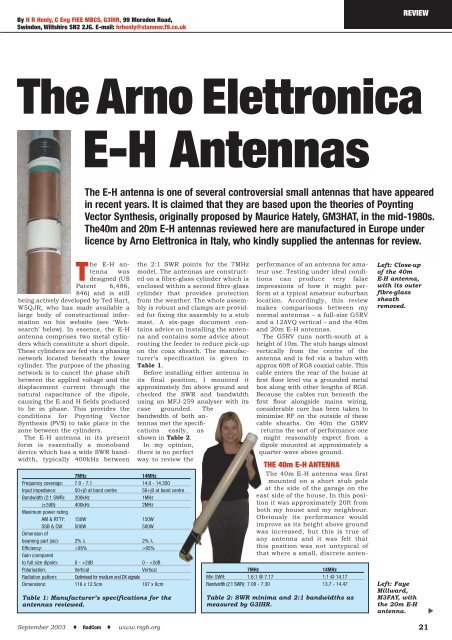
The Arno Elettronica<br />
E-H <strong>Antennas</strong><br />
T<br />
he E-H antenna<br />
was<br />
designed (US<br />
Patent 6,486,<br />
846) and is still<br />
being actively developed by Ted Hart,<br />
W5QJR, who has made available a<br />
large body of constructional information<br />
on his website (see ‘Websearch’<br />
below). In essence, the E-H<br />
antenna comprises two metal cylinders<br />
which constitute a short dipole.<br />
These cylinders are fed via a phasing<br />
network located beneath the lower<br />
cylinder. The purpose of the phasing<br />
network is to cancel the phase shift<br />
between the applied voltage and the<br />
displacement current through the<br />
natural capacitance of the dipole,<br />
causing the E and H fields produced<br />
to be in phase. This provides the<br />
conditions for Poynting Vector<br />
Synthesis (PVS) to take place in the<br />
zone between the cylinders.<br />
The E-H antenna in its present<br />
form is essentially a monoband<br />
device which has a wide SWR bandwidth,<br />
typically 400kHz between<br />
The E-H antenna is one of several controversial small antennas that have appeared<br />
in recent years. It is claimed that they are based upon the theories of Poynting<br />
Vector Synthesis, originally proposed by Maurice Hately, GM3HAT, in the mid-1980s.<br />
The40m and 20m E-H antennas reviewed here are manufactured in Europe under<br />
licence by Arno Elettronica in Italy, who kindly supplied the antennas for review.<br />
7MHz 14MHz<br />
Frequency coverage: 7.0 - 7.1 14.0 - 14.350<br />
Input impedance: 50+j0 at band centre 50+j0 at band centre<br />
Bandwidth (2:1 SWR): 200kHz 1MHz<br />
(±3dB): 400kHz 2MHz<br />
Maximum power rating<br />
AM & RTTY: 150W 150W<br />
SSB & CW: 500W 500W<br />
Dimension of<br />
beaming part (sic): 2% λ 2% λ<br />
Efficiency: >95% >95%<br />
Gain (compared<br />
to full size dipole): 0 - +2dB 0 - +2dB<br />
Polarisation: Vertical Vertical<br />
Radiation pattern: Optimised for medium and DX signals<br />
Dimensions: 116 x 12.5cm 107 x 8cm<br />
Table 1: Manufacturer’s specifications for the<br />
antennas reviewed.<br />
September 2003 ♦ RadCom ♦ www.rsgb.org<br />
the 2:1 SWR points for the 7MHz<br />
model. The antennas are constructed<br />
on a fibre-glass cylinder which is<br />
enclosed within a second fibre-glass<br />
cylinder that provides protection<br />
from the weather. The whole assembly<br />
is robust and clamps are provided<br />
for fixing the assembly to a stub<br />
mast. A six-page document contains<br />
advice on installing the antenna<br />
and contains some advice about<br />
routing the feeder to reduce pick-up<br />
on the coax sheath. The manufacturer’s<br />
specification is given in<br />
Table 1.<br />
Before installing either antenna in<br />
its final position, I mounted it<br />
approximately 5m above ground and<br />
checked the SWR and bandwidth<br />
using an MFJ-259 analyser with its<br />
case grounded. The<br />
bandwidth of both antennas<br />
met the specifications<br />
easily, as<br />
shown in Table 2.<br />
In my opinion,<br />
there is no perfect<br />
way to review the<br />
performance of an antenna for amateur<br />
use. Testing under ideal conditions<br />
can produce very false<br />
impressions of how it might perform<br />
at a typical amateur suburban<br />
location. Accordingly, this review<br />
makes comparisons between my<br />
normal antennas – a full-size G5RV<br />
and a 12AVQ vertical – and the 40m<br />
and 20m E-H antennas.<br />
The G5RV runs north-south at a<br />
height of 10m. The stub hangs almost<br />
vertically from the centre of the<br />
antenna and is fed via a balun with<br />
approx 60ft of RG8 coaxial cable. This<br />
cable enters the rear of the house at<br />
first floor level via a grounded metal<br />
box along with other lengths of RG8.<br />
Because the cables run beneath the<br />
first floor alongside mains wiring,<br />
considerable care has been taken to<br />
minimise RF on the outside of these<br />
cable sheaths. On 40m the G5RV<br />
returns the sort of performance one<br />
might reasonably expect from a<br />
dipole mounted at approximately a<br />
quarter-wave above ground.<br />
THE 40m E-H ANTENNA<br />
The 40m E-H antenna was first<br />
mounted on a short stub pole<br />
at the side of the garage on the<br />
east side of the house. In this position<br />
it was approximately 20ft from<br />
both my house and my neighbour.<br />
Obviously its performance would<br />
improve as its height above ground<br />
was increased, but this is true of<br />
any antenna and it was felt that<br />
this position was not untypical of<br />
that where a small, discrete anten-<br />
7MHz 14MHz<br />
Min SWR: 1.6:1 @ 7.17 1:1 @ 14.17<br />
Bandwidth (2:1 SWR): 7.08 - 7.30 13.7 - 14.47<br />
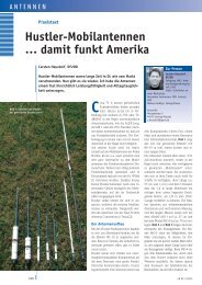
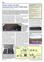
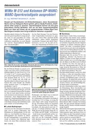
Left: Close-up<br />
of the 40m<br />
E-H antenna,<br />
with its outer<br />
fibre-glass<br />
sheath<br />
removed.<br />
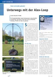
Left: Faye<br />
Millward,<br />
M3FAY, with<br />
the 20m E-H<br />
antenna.<br />
Table 2: SWR minima and 2:1 bandwidths as<br />
measured by G3IHR. ▲<br />
21
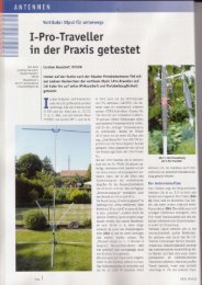
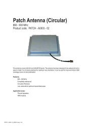
Right: 20m E-H<br />
antenna<br />
(centre) at 30ft<br />
and<br />
approximately<br />
20ft from one<br />
end of the<br />
G5RV. The 40m<br />
antenna is<br />
mounted on the<br />
side of the<br />
garage<br />
(extreme right).<br />
▲<br />
REVIEW<br />
Test G5RV Reference<br />
antenna<br />
(‘S’ units)<br />
1 6.1<br />
2 6.5<br />
3 6.5<br />
4 6.5<br />
5 7.0<br />
Table 3: The<br />
average signal<br />
level in ‘S’<br />
points from the<br />
G5RV reference<br />
antenna over all<br />
three stations<br />
for each of the<br />
five tests.<br />
na had to be used. It was used in<br />
this position for several days and a<br />
number of QSOs were made with<br />
signal reports comparing well with<br />
the G5RV. However, I decided that<br />
a fairer comparison could be made<br />
if I temporarily replaced my 2m<br />
Yagi with this antenna at a height<br />
of 30ft and approximately 20ft<br />
from one end of the G5RV.<br />
Comparison tests are difficult to<br />
make for several reasons. Firstly,<br />
one relies heavily upon the cooperation<br />
of many other amateurs of<br />
whom only a few will be disposed to<br />
help through several changes of<br />
antenna. Accordingly, the majority<br />
of the contacts used here only rely<br />
upon comparison of the received signal.<br />
A single comparison could produce<br />
a result that was entirely due<br />
to chance and not the change in<br />
antenna!<br />
The major element of this review<br />
is a summary of the performance<br />
that I observed over the period of the<br />
review and under a reasonable<br />
range of propagation conditions. A<br />
second element of the review is<br />
based upon a small number of tests<br />
conducted with three stations on<br />
40m. In these tests each station<br />
recorded their ‘S’ meter reading for<br />
the reference G5RV and the E-H<br />
antenna. The receiving station in<br />
the test was not appraised of the<br />
order of the tests at the time. All<br />
results were confirmed later by e-<br />
Test Stn 1 Stn 2 Stn 3<br />
1 -3 -0.5 +1<br />
2 -3 -0.5 -1<br />
3 -4 -0.5 -1<br />
4 -3 0 -1<br />
5 -3 -0.5 -1.5<br />
Mean: -3.2 -0.4 -0.7<br />
Distance (km) 375 474 475<br />
Table 4: 40m E-H antenna<br />
received signal compared with<br />
reference antenna (‘S’ units).<br />
Total Relative SignalLevel (‘S’ units)<br />
Call area QSOs +3 +2 +1 0 -1 -2<br />
G 13 - - 4 8 1 -<br />
DL 17 1 1 7 8 - -<br />
F 8 - - - 8 - -<br />
EA 2 - - - 1 - 1<br />
I 3 - - - 3 - -<br />
OH 1 - - - 1 - -<br />
OK 1 - - - 1 - -<br />
HA 1 - - - - 1 -<br />
PA 1 - - 1 - - -<br />
LZ 1 - 1 - - - -<br />
4X 1 1 - - - - -<br />
UR 2 - - 1 1 - -<br />
UA4 1 - - - - 1 -<br />
W/K 9 - - - 7 1 1<br />
VE 4 - - 2 1 1 -<br />
PY 1 - - 1 - - -<br />
VU* 2 2 - - - - -<br />
Totals: 68 4 2 16 39 5 2<br />
Table 5: Comparison of<br />
received signal strengths from<br />
various call areas. The<br />
difference is 40m E-H antenna<br />
compared with G5RV; units are<br />
‘S’ points. (* = Heard but not<br />
contacted.)<br />
mail. In order not to try the patience<br />
of the stations who kindly assisted<br />
in these tests each test was only<br />
repeated five times, ie five groups of<br />
three tests with the order rotated<br />
pseudo-randomly. Obviously all the<br />
tests with all stations could not take<br />
place simultaneously, so propagation<br />
conditions added another variable,<br />
the effect of which could only<br />
be estimated.<br />
Table 3 averages the signal level<br />
from the reference antenna over all<br />
three stations for each of the tests<br />
and it indicates that propagation to<br />
all three stations remained sensibly<br />
constant during the period of the<br />
tests, ie within ±0.5 ‘S’ point.<br />
In Table 4 I have calculated the<br />
difference between the received signal<br />
from the standard antenna and<br />
that from the E-H antenna for each<br />
test. At first sight this would suggest<br />
that the signal from the E-H<br />
was consistently below that of the<br />
reference antenna. However, Table<br />
3 indicates a one ‘S’ point spread in<br />
the average received signal so the<br />
results deserve a more detailed<br />
examination. The question to ask<br />
here is whether there were significant<br />
differences between the two<br />
antennas, if the recorded differences<br />
were due to other factors, or<br />
if they could have occurred just by<br />
chance. If the probability that the<br />
observed difference occurred by<br />
chance was 1 in 100, the difference<br />
between the antennas was highly<br />
significant, as was the difference<br />
between the observations of the<br />
three stations. This latter difference<br />
was consistent with different station<br />
equipment and different propagation<br />
paths. So we can conclude<br />
from these tests that the E-H antenna<br />
performance was between 0.5<br />
and 3.0 ‘S’ points below the G5RV<br />
with a mean of 1.4 averaged over<br />
the three stations.<br />
How did this result compare with<br />
operational experience? The majority<br />
of contacts on 40m during the review<br />
period have been inter-G and continental,<br />
the more numerous being with<br />
G, DL and F. On average, the difference<br />
was small but the standard deviation<br />
shows considerable variability.<br />
With the remainder of Europe, east to<br />
beyond the Urals and south to Italy,<br />
Spain and Greece, north to Norway<br />
and Sweden very similar results were<br />
obtained. During a CW contest contacts<br />
were made with N2, K3, N9 and<br />
VE1; serial numbers were deliberately<br />
only sent once and were received<br />
without repetition - together with the<br />
obligatory 599! Two VU stations were<br />
heard but not worked; these were<br />
both at S7 on the E-H antenna and<br />
only about S4 on the G5RV. This latter<br />
points up more than any other<br />
result the very different radiation<br />
characteristics of the two antennas.<br />
Other semi-DX worked during the<br />
review were VO1 and VE3 during the<br />
‘BERU’ contest, UA9 and PY7.<br />
Reports from these contacts compared<br />
well with those I normally<br />
enjoy with the G5RV. On the odd<br />
occasion when I sought co-operation<br />
to compare with the G5RV the signal<br />
report was in favour of the E-H.<br />
Table 5 summarises the received<br />
signal levels as compared with the<br />
G5RV over various call areas.<br />
Bearing in mind these reports<br />
embody several variables other than<br />
the two aerials, it is reasonable to<br />
conclude that on the longer distance<br />
paths the E-H performance is on a<br />
par with the G5RV; on shorter<br />
paths, ie inter-G, it is likely to be<br />
lower than the G5RV. This is consistent<br />
with what one might expect if<br />
comparing a horizontal and a vertical<br />
antenna and was borne out by<br />
the results in Table 4 in which the<br />
two stations who were located furthest<br />
away (Stations 2 and 3)<br />
observed the smaller differences.<br />
THE 20m E-H ANTENNA<br />
The 20m E-H antenna was originally<br />
mounted on a 5m pole in the centre of<br />
my garden, with a consequential coax<br />
22 September 2003 ♦ RadCom ♦ www.rsgb.org
un of some 25m to the shack. In this<br />
position I could conveniently measure<br />
its SWR bandwidth and also assess<br />
the effect, if any, of inserting braidbreakers<br />
in the feeder near to the<br />
antenna. It was then transferred to<br />
the site previously occupied by the<br />
40m E-H antenna.<br />
Organised tests such as that conducted<br />
with the 40m E-H were not<br />
contemplated. Instead, the received<br />
signal was compared with a 12AVQ<br />
vertical antenna, mounted at ground<br />
level approximately 25m from the<br />
shack. Where the opportunity arose,<br />
transmission comparisons were made<br />
between the two antennas also.<br />
Unfortunately for much of the<br />
review period, short skip conditions<br />
prevailed and most contacts were<br />
with stations in Europe. The E-H<br />
antenna compared very favourably<br />
with the 12AVQ and often with the<br />
G5RV which is, of course quite directional<br />
on this band. On receive its<br />
characteristics are almost identical<br />
with the 12AVQ, ie a considerable<br />
increase in solar noise as compared<br />
with the G5RV which exhibits a quiet<br />
background on 14MHz, and an<br />
improved response to stations over<br />
500km. The same increase in solar<br />
noise was noted with the 7MHz E-H<br />
antenna suggesting that it has an<br />
additional high-angle lobe.<br />
Sixty-five contacts were made<br />
over a period from 8 March to 21<br />
April 2003 at various times during<br />
the day. Outside the short-skip that<br />
prevailed most of the time, some DX<br />
was worked, notably 579 from VP5<br />
against a considerable pile-up;<br />
three JA stations in a row during a<br />
contest; CT3 and EA8. Ed, W2HTI,<br />
in North Carolina gave me 569 on<br />
the E-H and 579 with the 12AVQ,<br />
whilst Ted, F5MW, in Marseille<br />
found negligible difference between<br />
the two antennas and the G5RV.<br />
Similarly in a QSO with Lars,<br />
SM6FPZ, where my signal was 599<br />
on both antennas. The E-H<br />
appeared at all times to be omnidirectional<br />
in the horizontal plane<br />
but the solar noise level at times<br />
was detrimental. In particular,<br />
VU2VJT was worked on the 12AVQ<br />
but was inaudible on the E-H.<br />
Table 6 summarises these results<br />
and gives the average signal report<br />
received from each area. The caveats<br />
given for the 40m comparisons apply<br />
here too. The variation against the<br />
12AVQ was less marked and the<br />
antenna held its own very well.<br />
CONCLUSIONS<br />
To summarise, from an operational<br />
stand-point both of the E-H antennas<br />
performed extremely well as<br />
general-purpose antennas, exhibiting<br />
no significantly different performance<br />
to my normal antennas.<br />
They both exhibit characteristics<br />
that are similar to a ground-plane<br />
antenna or a vertical dipole, showing<br />
some enhanced low-angle radia-<br />
September 2003 ♦ RadCom ♦ www.rsgb.org<br />
tion as compared with a horizontal<br />
antenna. Both antennas worked<br />
quite well at ground level but<br />
only compared<br />
favourably with the<br />
other antennas<br />
when operated<br />
under similar<br />
conditions, ie<br />
at a similar<br />
height and position<br />
with relation<br />
to surrounding<br />
objects. The nature<br />
of the above tests preclude<br />
any possibility of verifying the<br />
manufacturers claim of 0 to+2dB<br />
over a dipole.<br />
Where space is restricted I believe<br />
they will produce comparable or<br />
better results than a wire antenna<br />
that has to be bent to fit into a<br />
restricted space, eg a loft, or other<br />
‘stealth’ antennas. The main disadvantage<br />
is that the E-H is a monoband<br />
antenna.<br />
The E-H antenna is claimed to produce<br />
a better signal-to-noise ratio on<br />
receive than a conventional Hertzian<br />
antenna. I did not experience this on<br />
either band; the response to local<br />
noise was lower, but as noted above<br />
the level of solar noise was equal to<br />
that of my 12AVQ vertical.<br />
One problem that needs to be<br />
resolved is that of RF on the coax<br />
sheath. In common with many<br />
installations I have to route my<br />
feeders under floors and alongside<br />
mains cables. It is essential that RF<br />
on the cable sheaths is kept to a<br />
minimum. To this end I make frequent<br />
use of ferrite toroid chokes.<br />
The manufacturers claim that any<br />
RF on the feeder is due to pick-up<br />
within the intense field of the antenna<br />
and not due to any commonmode<br />
currents caused by mis-match<br />
at the antenna. However, they also<br />
warn that the use of a choke near<br />
the antenna will cause phase<br />
changes that may detune the antenna<br />
and we cannot have it both ways!<br />
On the 40m E-H I have successfully<br />
used a choke in the coax feed where<br />
it enters the house without causing<br />
any detuning of the antenna. RF in<br />
the shack is negligible although the<br />
field strength from the antenna is<br />
very high as compared with that<br />
measured from the G5RV. On 20m it<br />
is a different story. With a braidbreaking<br />
choke closer to the antenna<br />
than 10m the antenna was seriously<br />
detuned. In its present position<br />
at 10m above ground I have a<br />
six-turn coil of coax and a coax<br />
braid-breaker but there is still some<br />
RF in the shack. There has been<br />
considerable discussion of this<br />
problem on the Internet E-H forum<br />
and some solutions have been suggested.<br />
I believe it is important that<br />
the manufacturer should address<br />
this problem. This antenna will I am<br />
sure be attractive to those amateurs<br />
who have little space or suffer from<br />
planning restrictions. In those situations,<br />
it is essential that RF can be<br />
piped around with minimal EMC<br />
problems.<br />
I understand that an 80m E-H<br />
antenna is available and a design for<br />
160m is on the cards. I can imagine<br />
that mounting these at any height<br />
may pose significant problems due to<br />
their size. Nevertheless, it will be<br />
interesting to see how they perform<br />
on bands where lack of real estate<br />
poses an even greater problem.<br />
I am indebted to Pat, PA3EZJ;<br />
Howard, EI5EG, and Stan, GM3KXQ,<br />
for their time and patience in assisting<br />
me in the above tests. Thanks too<br />
to the manufacturer, Arno Elettronica,<br />
Via Volteranna, 208/1<br />
56033 Capannoli (PISA), Italy, for the<br />
loan of the antennas reviewed. The<br />
price of the 7.0 and 14.0MHz antennas<br />
is 144 euros (approx £100) each<br />
inc VAT (P&P extra). Models are<br />
available for the bands from 3.5MHz<br />
to 50MHz.<br />
Editor’s note: the manufacturers<br />
have informed us that the power rating<br />
of all models of E-H antenna has<br />
now been increased to 2kW on SSB<br />
and CW, and 500 watts on RTTY or<br />
AM. Each E-H antenna is also now<br />
equipped with an external coaxial<br />
sleeve fine tuning system that allows<br />
it to be tuned to exactly the desired<br />
frequency on each band. ◆<br />
Total Relative Signal Level Report received<br />
Call area QSOs +1 0 -1 (average)(‘S’ units)<br />
DL, F, PA 11 1 7 3 7<br />
UA (European) 11 6 4 1 7<br />
UA (Asian) 12 7 3 2 6<br />
Other E Europe 6 1 5 - 8<br />
Scandinavia 4 - 4 - 8<br />
S Europe 11 3 5 3 8<br />
CT3 / EA8 3 2 1 - 7<br />
W 3 - 2 1 5<br />
VP5 1 - 1 - 7<br />
JA 3 - 3 - 9*<br />
Totals: 65 20 35 10<br />
Table 6: 20m E-H antenna received signal level<br />
compared with 12AVQ vertical (* = Contest report!)<br />
WEBSEARCH<br />
Arno Elettronica www.eheuroantenna.com<br />
Ted Hart, W5QJR www.eh-antenna.com<br />
Internet E-H forum http://groups.yahoo.com/group/eh-antenna<br />
23