
Create successful ePaper yourself
Turn your PDF publications into a flip-book with our unique Google optimized e-Paper software.
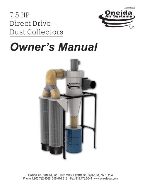
7.5 HP<br />
Direct Drive<br />
Dust Collectors<br />
Owner’s <strong>Manual</strong><br />
<strong>Oneida</strong> <strong>Air</strong> <strong>Systems</strong>, Inc. 1001 West Fayette St., Syracuse, NY 13204<br />
Phone 1.800.732.4065 315.476.5151 Fax 315.476.5044 www.oneida-air.com<br />
ZBM000006<br />
5_10
Thank You for Choosing an <strong>Oneida</strong> <strong>Air</strong> <strong>Systems</strong> Product!<br />
OAS manufactures and sells dust collection equipment only. Our qualifi ed technicians and sales staff<br />
are available 7:30am - 6:00pm EST Mon. - Thurs. and 7:30am - 5:00pm EST Fri. to answer any questions<br />
concerning OAS products and dust collection. Call for ductwork design and ductwork quotes,<br />
including system pricing and shipping cost.<br />
Read the entire Owner’s <strong>Manual</strong> before installing or operating system!<br />
7.5hp Direct Drive © O.A.S. 2009<br />
Proudly<br />
Made in<br />
the USA<br />
Table of Contents Page<br />
I.<br />
II.<br />
III.<br />
IV.<br />
V.<br />
VI.<br />
VII.<br />
VIII.<br />
IX.<br />
X.<br />
XI.<br />
XII.<br />
XIII.<br />
XIV.<br />
XV.<br />
XVI.<br />
System Start-Up Information<br />
General Assembly<br />
General Specifi cations & Fan Performance Curve<br />
Dimensions<br />
Stand Assembly<br />
General Assembly Instructions<br />
Fan / Blower Maintenance<br />
Filter Maintenance<br />
Wire Diagram<br />
Accessories<br />
Troubleshooting<br />
Fire Hazards - Read Before Installing System<br />
Terms and Conditions<br />
Filter Effi ciency Gauge Instructions<br />
Fan Motor Lunbrication<br />
Supplemental Instructions for Magnetic Motor Starters<br />
1<br />
2<br />
3<br />
4<br />
5<br />
6<br />
7 - 8<br />
9<br />
10<br />
11<br />
12<br />
13<br />
14<br />
15<br />
16<br />
17<br />
18 - 20
I. System Start-Up Information<br />
1. Read the installation and maintenance instructions as well as the recommended safety practices in<br />
this manual.<br />
2. Install Ductwork completely:<br />
(A.) Seal ductwork with silicone sealant or duct tape.<br />
(B.) Have Dust Bin in place and sealed.<br />
3. Have licensed electrician wire Fan / Blower according to wire diagram in this owner’s manual.<br />
4. Have a licensed electrician check current draw on motor with all gates open. Current draw should not<br />
exceed maximum motor amperage. (OAS is not responsible for destroyed motors.)<br />
2<br />
Caution<br />
The Dust Collector & Fan / Blower is heavy! Handling and installation<br />
should always be performed by experienced and trained personnel who<br />
have experience with rotary equipment. In addition to the following instructional<br />
manual, care should be taken to ensure compliance with specifi c<br />
safety requirements mandated bt federal, state and local codes.<br />
Warning<br />
Do not operate Fan / Blower without connecting ductwork. Never operate<br />
Fan / Blower without belt shaft guard in place. Keep clear of exhaust.<br />
Keep hands and objects clear of inlet and outlet.<br />
Warning Warning<br />
Check amperage draw during operation with all blast gates open. Make<br />
certain amperageis not outside operating limit indicated on motor plate!<br />
If amperage is too high - shut down immediately! (See Troubleshooting<br />
section.)<br />
7.5hp Direct Drive © O.A.S. 2009
III. General Specifi cations & Fan Performance Curves<br />
Physical and Electrical Data for 7.5hp Direct Drive <strong>Systems</strong><br />
System Performance Dust Bin<br />
7.5hp - 2725 max cfm @ 1.7” S.P. 55 Gal. Steel Drum<br />
Large Dust Bins available<br />
System Dimensions<br />
Height w/ 55 Gal. Drum: 130”<br />
Footprint: 80.3” x 39.2”<br />
Fan Wheel Diameter: 16” <strong>Air</strong> Foil Design<br />
Cyclone Inlet: 10”<br />
Integral Fan Blower - 7.5hp<br />
TEFC 60 Hz Motor - Single Phase<br />
Insulation Class: F4<br />
Voltage: 208 - 230/460<br />
Amperage: 19.6 - 18.4 / 9.2<br />
Made in U.S.A.<br />
15<br />
13<br />
11<br />
9<br />
7<br />
5<br />
3<br />
1<br />
800 1300 1800 2300 2800<br />
7.5hp Direct Drive © O.A.S. 2009<br />
Options<br />
<strong>Air</strong> Locks<br />
Hoppers<br />
Silencers<br />
Bag Gripper<br />
Drum Dolly<br />
Bin Level Indicator<br />
External Cartridge Filter<br />
2 Pleated Cartridge - 260 Sq. Ft.<br />
Spun-Bonded polyester BIA ZH1/487 test - Rated C<br />
Captures 99.99% of test material over 20 microns<br />
Captures 99,9% of test material between 0.2 - 2<br />
microns @ 11 fpm<br />
3
4<br />
IV. Dimensions<br />
For minimum mounting<br />
heights with 55 gal. drum<br />
7.5hp Direct Drive © O.A.S. 2009
V. Angle Iron Stand<br />
7.5hp Direct Drive © O.A.S. 2009<br />
5
VI. Assembly Instructions<br />
Instructions for assembly of Fan Blower Housing and Barrel of the <strong>Oneida</strong> Models .*<br />
1. Push clips onto inside circle on Fan Housing, making sure clip is pushed all of the way on, that the bolt<br />
holes are in alignment with the clip holes and that the small barrel on the clip is on the INSIDE of the Fan<br />
Housing as shown in diagram.<br />
2. Stick the gasket material around the Fan Housing as shown in the diagrams, outside of the bolt circle.<br />
Making sure of a complete seal. Dust collection systems cannot operate effectively without being tightly<br />
sealed with no air leaks.<br />
3. Put bolt through washer, then into appropriate bolt holes in Fan Housing and Barrel. Tighten bolts so they<br />
all are snug, then go back and finish tightening the bolts in a star pattern.<br />
6<br />
Proportions and sizes of parts may be<br />
exaggerated for purposes of explanation.<br />
Gasket<br />
Material<br />
Fan<br />
Housing<br />
Gasket<br />
Material<br />
Collector<br />
Barrel<br />
Bolt<br />
Washer<br />
Clip<br />
It is CRITICAL that this part of<br />
the clip is put on the inside of<br />
the Fan Blower Housing as<br />
shown here. Otherwise you<br />
will not get the seal needed<br />
for complete dust collection!<br />
Clip<br />
Bolt<br />
Motor Plate<br />
Washer<br />
Gasket material goes<br />
outside of clip holes<br />
on top and bottom of<br />
fan housing.<br />
7.5hp Direct Drive © O.A.S. 2008
VI. Assembly Instructions<br />
Fan / Blower is shipped strapped to Cyclone Barrel. It is NOT<br />
attached properly to the unit for operation. You must bolt them<br />
together. Follow the instructions below.<br />
System is extremely heavy so have adequate help<br />
and take appropriate safety precautions.<br />
1. Before installation you must fi rst decide how you want the unit oriented<br />
in your shop / work area. A.) Decide which side of the stand you<br />
want the fi lters on. This will determine where you place the fi lter plate<br />
and the orientation of the fan / blower outlet. B.) Decide where the ductwork<br />
feeding the unit will be located. This will determine the orientation<br />
of the cyclone barrel to the fan / blower assembly.<br />
2. Place gasket material onto the cyclone barrel as shown. Lower the<br />
fan / blower assembly onto the barrel orienting the outlet of the blower<br />
at the desired angle to the inlet of the barrel (based on the location of<br />
the ductwork in your shop.) Try to align the holes in the bottom of the<br />
blower to the holes in the barrel as close as possible. From inside the<br />
barrel, bolt the barrel to the blower using the hardware included. Partially<br />
tighten as many bolts as possible by reaching through the inlet,<br />
then turn the unit on its side to bolt the remaing bolts<br />
3. Apply the gasket material to the fl ange on the fan / blower. Bolt the<br />
outlet square to round to the outlet.<br />
4. Place self-stick gasket around cyclone fl ange. Bolt the fan housing<br />
and cyclone barrel to the cyclone cone but leave out the bolts that will<br />
go through the front and back holes in the stand. Lay the stand down,<br />
then bolt the collector to the stand, then lift the stand upright. When<br />
you put in the front and back bolt, you need to add an extra washer<br />
between the fl ange and the stand as in diagram 3. Another way is to<br />
position the cone on the stand, then lift the assembled Fan / Blower<br />
and Barrel on top of the cone. Then bolt the Barrel and Cone to the<br />
Stand, making sure you add an extra washer between the Flange and<br />
the Stand as shown in diagram 3.<br />
5. After the collector is attached to the stand, band clamp the 12” dia.<br />
fl ex hose to the outlet square to round and the top of the included splitter.<br />
Connect the 10” fl ex hoses to the legs of the splitter and the plenum<br />
fi lter inlets as shown below. You must cut the 10” hose into (3) pieces of<br />
(2)18” for the fi lter connection and 24” for the drum connection.<br />
12” Flex Hose<br />
10” Flex Hose<br />
7.5hp Direct Drive © O.A.S. 2008<br />
3.<br />
Square to<br />
Round<br />
Bolt<br />
Washer<br />
Barrel Flange<br />
Cone Flange<br />
Washer<br />
Stand<br />
Washer<br />
Hex Nut<br />
Plenum can be<br />
attached to either<br />
side of the stand.<br />
Fan / Blower<br />
7
VI. Assembly Instructions (Cont.)<br />
6. Attach the fi lters to the plenum with the included J-Clamps, making<br />
sure the included silencers are in place in the top of the fi lters. Then<br />
attach the dust pans to the bottom of the fi lters.<br />
7. Attach fl ex hose to bottom of collector and to lid of dust drum.<br />
Securely fasten hose clamps. There must be an air tight seal<br />
between the collector and dust drum.<br />
8. Make sure the dust drum lid sits securely and the rubber gasket<br />
on the bin lid is in place on the drum. Maintain an air tight seal between<br />
cyclone and dust drum to prevent motor from overloading.<br />
8<br />
Important:<br />
Do not operate the collector until the dust drum is in place<br />
and the collector is air tight or motor damage could result!<br />
Stay clear of fan exhaust while collector is operating.<br />
9. Attach the duct work from the woodworking machines to<br />
the inlet of the collector.<br />
4.<br />
7.5hp Direct Drive © O.A.S. 2009
VI. Fan / Blower Maintenance<br />
A high pressure blower requires a certain amount of resistance which will prevent motor over amperage.<br />
Make sure power source matches wire voltage confi gurations.<br />
Check set screw and key in fan wheel, make sure fan wheel is secure. Fan blower should not vibrate.<br />
1. Electical - Failure to follow instructions and safe electrical procedures could result in serious injury or death. Disconnect<br />
all power and discharge all capacitors before servicing. Install and ground per local and national codes. Consult a<br />
licensed electrician with questions or if repairs are required.<br />
Electrical Connections_<br />
A.) All wiring, fusing, and grounding must comply with National Electrical Codes and local codes.<br />
B.) To determine proper rotation and voltage connections, refer to the wire diagram of this manual.<br />
C.) Use the proper size of line current protection and motor controls as required by the National Electrical Code and local<br />
codes. Recommended use is 125% of full load amps as shown on the nameplate for motors with 40 degrees celsius<br />
ambient and a service factor over 1.0. Recommended use is 115% of full load amps as shown on nameplate for all other<br />
motors. Do not use protection with larger capacities than recommended. Three phase motors must have all three phases<br />
protected.<br />
2. Cleanliness - Keep both the interior and exterior of the motor free from dirt, water, oil, and grease.<br />
3. Safety- Motors should be installed, protected and fused in accordance with the latest issue of National Electrical<br />
Code, NEMA Standard Publication No. 2 MG 2 and local codes. Rotating parts such as pulleys, coupling, external fans,<br />
and unusual shaft extentions should be permanently guarded. Keep hands and clothing away from moving parts. Electrical<br />
repairs should be made by trained, qualifi ed personnel only.<br />
4. Service - Notice - If lubrication instructions are shown on the motor nameplate, they will supercede this general<br />
instruction.<br />
Warning! Rotating Fan Blades. Keep Objects Clear of Inlet and Outlet!<br />
7.5hp Direct Drive © O.A.S. 2009<br />
9
VII. External Filter Maintenance<br />
All steps should be done with a dust mask and eye protection. Proper fi lter cleaning<br />
should not be neglected. A dirty fi lter can affect dust collector operation and<br />
fi lter life.<br />
1. Compressed air from outside.<br />
Blast air along pleats of the fi lter at about a 20 degree angle.<br />
Blast air out and away from you or anyone in the general area.<br />
Keep air nozzle at least 6” from fi lter. Closer blasts may damage<br />
material. This operation should be done with fi lter on the<br />
unit. Dust is trapped inside fi lter so it will not make a mess.<br />
10<br />
Filter must be cleaned regularly or fi lter damage may<br />
result. If gauge reaches 3, it is time to clean your fi lter.<br />
Never allow gauge to reach 5. You could destroy<br />
your fi lter. See page 16.<br />
2. Empty Dust Bin.<br />
Wait a few minutes for internal dust to settle then unscrew<br />
thumb nuts from J-Hooks and remove dust bin. Empty dust<br />
carefully. Replace dust bin. Do not over tighten thumb nuts.<br />
Filter<br />
J-Hook<br />
Dust Bin<br />
Thumb Nut<br />
6”<br />
Caution: Fine dust collected in fi lter is hazardous to your health! Do not breathe!<br />
7.5hp Direct Drive © O.A.S. 2009
VIII. Single and Three Phase Wire Diagram<br />
Use wiring diagram on motor plate if different from below.<br />
Wiring should always be done by a licensed electrician!<br />
- Electrically insulate all connections.<br />
- For counter-clockwise rotation, looking from top of motor down.<br />
7.5hp Three Phase<br />
Baldor Motor / 208 - 230/460v / 19 - 17/8.6 amps / TEFC / C Face / 3450 rpm<br />
208 / 230 Volts 460 Volts<br />
L1<br />
L2<br />
L3<br />
4<br />
5<br />
6<br />
1 & 7<br />
2 & 8<br />
3 & 9<br />
To reverse rotation interchange any two line leads.<br />
7.5hp Direct Drive © O.A.S. 2009<br />
L1<br />
L2<br />
L3<br />
1<br />
2<br />
3<br />
7 & 4 Tie Together<br />
Tie Together 8 & 5 Tie Together<br />
9 & 6 Tie Together<br />
Check rotation after wiring.<br />
Wire for counter-clockwise rotation.<br />
Motor<br />
Wire<br />
Box<br />
Green<br />
Chassis<br />
Screw<br />
Ground: Connect house ground<br />
wire to green chassis screw in<br />
motor wire housing box.<br />
11
IX. Accessories<br />
Bin Level Monitor - AIB000000 - Provides level sensing for dry bulk solids. The monitor operates<br />
by using a 1 rpm synchronous motor to rotate a paddle. When paddle rotation is impeded<br />
by material surrounding it, the motor is de-energized and triggers a SPDT snap switch. The<br />
snap switch can be used in conjunction with a motor starter to turn equipment off or provide<br />
alarm functions.<br />
Bin Level Sensor Assembly w/ Strobe Light - AXB000000<br />
The BAG Gripper<br />
ABX000000<br />
The BAG Gripper provides the ability to use convenient plastic bags inside your dust<br />
drum. It provides a constant, negative pressure on the outside surface of the plastic bag<br />
that keeps it pulled tight against the sides of the dust drum. Can be used with 35 and 55<br />
gal. barrels. Must be wired into your system.<br />
Dust Bin Options - (Must order custom mounting stand.)<br />
1. Multiple Drums -<br />
Custom order the System Mounting Stand for multiple drums or hoppers.<br />
Stand widths will vary depending on dust container.<br />
2. Hoppers -<br />
Large capacity hoppers from .5 cu. yd. to 3 cu. yd.<br />
3/15” reinforcing angle for added support - 3/16” plate body is 100% continuously MIG<br />
welded on inside - 3/8” rear cross brace angle (not 3/16”) - three 3” base channel - All<br />
angles are structural not formed.<br />
3. <strong>Air</strong> Locks -<br />
Rotary air locks provide an alternative to an air tight dust bin for larger volume capacity and<br />
less maintenance.<br />
Example - A 10” air lock will drop 1.85 cu. ft. / rev. of material.<br />
12<br />
TM<br />
4. Cone w/ Clean Out -<br />
Optional cone with clean out plate for use with airlocks.<br />
Dust Sentry AXB999110<br />
The <strong>Oneida</strong> Dust Sentry with adjustable IST (Infrared Sensing Technology), fl ashes a<br />
strobe light to alert you when the dust in your container reaches your preset level, telling<br />
you when it’s time to empty the container.<br />
Pat. Pending<br />
7.5hp Direct Drive © O.A.S. 2009
X. Troubleshooting<br />
Motor Overheating<br />
The motor’s internal circuit breaker will trip if the motor is overheating.<br />
Motor amperage too high - Shut system down.<br />
Caused By:<br />
System should be completely bolted and sealed together.<br />
Ductwork should be completely installed and sealed with sealant.<br />
<strong>Air</strong> leaks between the collector and dust bin.<br />
- The lid of the dust bin and the cyclone must be in place and sealed when operating the dust collector.<br />
- Make sure fl ex hose is not torn and the hose clamps are tight.<br />
- Check drum lid; cover should have a foam seal and be well seated.<br />
- Check for holes or leaks in the dust bin barrel.<br />
Motor not properly wired. Check wire connections.<br />
- Check motor rotation - See wire diagram<br />
Check breaker box. Make sure incoming power supply matches motor specifi cations.<br />
Poor Dust Pick-Up at Woodworking Machines<br />
Caused By:<br />
Improper motor rotation - Running backwards will reducr suction by 30%.<br />
Check length of duct runs and duct diameters compared to ductwork design guideline.<br />
Make sure all ductwork is sealed. Large air losses will occur even through small cracks in the ductwork.<br />
Use silicone, duct tape or duct mastic compound as a sealant.<br />
Check for air leaks between collector and dust bin.<br />
Close all unused blast gates at your woodworking machines.<br />
Examine hood design for weaknesses according to the ductwork guide.<br />
Check for a restricted pipe, too small a hood port or too small a branch line. See branch line diameter chart<br />
in ductwork guide.<br />
Be sure that your fi lter is clean. See fi lter cleaning directions.<br />
Filter Clogging<br />
Caused By:<br />
<strong>Air</strong> leakage between cyclone and dust bin. Cyclone and dust bin must be air tight. Even small leaks can will cause<br />
poor pre-separation in the cyclone.<br />
Large chips clogging the fi lter:<br />
- Check for a leak in the dust bin, fl ex coupling or lid. Check for split or torn fl ex coupling. (See also: Motor Overheating<br />
Section above.)<br />
- Make sure dust bin has not over fi lled. Dust bin should be emptied before dust reaches top of container.<br />
- Interruption of air fl ow, such as vacuuming chips with a fl ex hose connection, will increase fi lter maintenance.<br />
- Minimum 4” diameter pick up at tool location. Less than 4” will restrict air fl ow into collector and will increase fi lter<br />
maintenance, If there is not enough air entry in system, open more blast gates.<br />
- Make sure clamp around cyclone is tight and sealed with silicone.<br />
Excessive Vibration<br />
Caused By:<br />
Loose mounting bolts.<br />
Excessive system pressure or restriction of air due to closed blast gates.<br />
Accumulation of foreign material on the fan wheel.<br />
Inadequate support structure.<br />
7.5hp Direct Drive © O.A.S. 2009<br />
Note: If you continue<br />
to experience diffi culty<br />
with your collector, call<br />
<strong>Oneida</strong> <strong>Air</strong> <strong>Systems</strong> at<br />
1.800.732.4065 for assistance.<br />
13
XI. Fire Hazards<br />
14<br />
- Read Before Installing and Operating<br />
<strong>Oneida</strong> Collectors are designed for WOOD DUST only!!<br />
Wood shaping and cutting processes generate wood chips, shavings, and dust. These materials are considered combustible. <strong>Air</strong><br />
borne wood dust below 420 microns in size (,017 of an inch) in certain concentration ranges when ignited can defl agrate (burn quickly).<br />
An ignition source such as a spark or ember can ignite a dust mixture resulting in an expanding fl ame front which can cause an explosion<br />
if tightly contained. A disturbance that raises a cloud of accumulated fi ne dust can raise additional dust clouds, which can cause a<br />
series of explosions that can level an entire building. Until this type of fi re has been witnessed, it is diffi cult to believe the devastation.<br />
This type of fi re is rare but worth safeguarding against.<br />
The best way to avoid a wood shop fi re is to keep the shop clean. A shop ankle deep in dust with layers of fi ne dust everywhere is an<br />
accident waiting to happen. A good dust collection system reduces overall fi re hazards but also adds new concerns. A fi re hazard is still<br />
present. Combustible material is now in the dust collector and storage container.<br />
The following points are worth heeding:<br />
It is the buyer’s responsibility to follow all applicable federal, state, local, OSHA, NFPA, or authorities having jurisdiction codes and<br />
regulations when installing and operating this dust collector.<br />
Fire marshals may want the unit located outside of the building. If the collector is located inside the facility, controls such as spark<br />
detection, suppression, or explosion venting may be required.<br />
Most local jurisdictions consult or adopt NFPA (National Fire Protection Agency) codes. However, other codes may apply. Local<br />
codes may vary from jurisdiction to jurisdiction.<br />
NFPA 664 Code book, “Standard for the Prevention of Fires and Explosions in Wood Processing and Woodworking Facilities”, applies<br />
to woodworking operations that occupy areas of more than 5,000 sq. ft. or to areas where dust producing equipment requires an<br />
aggregate dust collection fl ow rate of more than 1500 cfm (cubic feet per minute). This exempts some small operators from the NFPA<br />
code 664, but other codes may apply in your jurisdiction. Consult your local Fire Marshall for help. Additional information can be found<br />
in NFPA Code Book 664.<br />
The customer assumes the responsibility for contacting their insurance underwriter with regard to specifi c application requirements of<br />
explosion venting or if additional fi re protection and safety equipment may be required.<br />
Do not use this product to collect other types of dust or fl ammable vapors.<br />
Fire or explosion may occur!<br />
- Never collect sparks from a bench grinder into a wood dust collector.<br />
- Never introduce sparks or sources of ignition into the dust collector.<br />
- Personnel should keep at least 20 feet away from unit.<br />
- Check dust bin frequently and before leaving the shop for smoldering material.<br />
Keep portable Fire Extinguishers handy.<br />
- The ABC type (dry chemical) is generally a good choice for small wood shops. Additional information on portable extinguishers<br />
can be found in NFPA 10 (Standards for Portable Fire Extinguishers).<br />
- Be especially careful with sanding units. They can produce concentrations of dust in the combustible range. Make certain enough<br />
air volume is at the suction point to capture all the particulate generated.<br />
- This high air volume will dilute the mixture below the lower limit of fl ammability. Be careful not to generate sparks into the sanding<br />
dust.<br />
- Empty dust bin and clean fi lter often, especially when sanding.<br />
- Don’t overload woodworking equipment, especially sanders. Excessive frictional heat can spontaneously ignite dust.<br />
Sparks can be generated in several ways:<br />
- High-speed sanders and abrasive planers may strike foreign material.<br />
- Saws and edgers may strike foreign material and create a red hot metal fragment.<br />
- Knots in hardwood can create frictional sparks.<br />
- Tramp metal when drawn into the collector can spark against ductwork.<br />
- Check wood stock for old nails and screws which can create red hot metal fragments.<br />
- Avoid using excessively large wood waste storage bins.<br />
- Always check storage bins for smoldering material before leaving for the day.<br />
- Electrically ground all equipment and ducting. Static sparks can ignite wood dust. (Avoid using PVC drainpipe).<br />
- Don’t allow accumulation of layers of fi ne dust on horizontal surfaces. (Especially overhead lights, electrical boxes, and fuse<br />
panels which can ignite dust).<br />
7.5hp Direct Drive © O.A.S. 2009
How to Order<br />
Phone - 1.800.732.4065 Toll-Free<br />
Our hours are Monday - Friday 8:30am - 5:00pm EST<br />
Internet - www.oneida-air.com<br />
You can shop on our online web store 24 hours a day.<br />
E-mail us at: info@oneida-air.com.<br />
<strong>Oneida</strong> tries to ship orders out in a timely manner, however sometimes delays and back orders are inevitable. <strong>Oneida</strong> will not be held responsible or liable for these<br />
conditions or the way they may effect your production. Back orders will be shipped when they are available. When orders are shipped UPS, UPS will notify you by<br />
e-mail. If shipped by Common Carrier, you can arrange for the trucking company to notify you and make arrangements for delivery. Shipping method is determined by<br />
<strong>Oneida</strong> <strong>Air</strong> <strong>Systems</strong> and is dependent upon material to be shipped and destination. You are not charged until your order is shipped.<br />
Please look over the shipped order very carefully in the presence of the delivery person for damage or incomplete shipment before signing the delivery receipt. Please<br />
note any tears or irregularities in shipping packaging, however slight, on the shipping delivery receipt. This could be an indication of extensive concealed damage. The<br />
shipping company will not take responsibility if the damage is not noted on the delivery receipt. In the event of shipping damage, call OAS Customer Service immediately<br />
at 1.800.732.4065 so we can expedite replacements. Please check in all parts within 3 days from receiving order. Notify OAS immediately of any missing or incorrect<br />
parts. OAS does not accept any claims for damage or shortage after 3 days from date of delivery.<br />
7.5hp Direct Drive © O.A.S. 2009<br />
Fax - 1. 315.476.5044<br />
You can fax your order in anytime and we will send you<br />
back a confi rmation by e-mail, fax or mail. Be sure to<br />
include your name and a daytime phone number<br />
Mail - <strong>Oneida</strong> <strong>Air</strong> <strong>Systems</strong>, Inc. 1001 W. Fayette St., Syracuse, NY 13204<br />
You can mail in your order and we will send you back a confi rmation by e-mail, fax or mail. Be sure to include your name and a daytime phone number.<br />
Terms and Conditions / Shipping<br />
Checking in Order<br />
Limited Warranty<br />
<strong>Oneida</strong> <strong>Air</strong> <strong>Systems</strong> warrants the products manufactured by <strong>Oneida</strong> <strong>Air</strong> <strong>Systems</strong>, for a period of 1 or more years depending on the product, to the original purchaser<br />
from the date of purchase unless otherwise specifi ed. Items not manufactured by <strong>Oneida</strong> <strong>Air</strong> <strong>Systems</strong> are limited to their own manufacturer’s warranties. All electrical<br />
items such as magnetic starters, remotes, sensors, pumps and accessories are limited to 90 days. <strong>Oneida</strong> <strong>Air</strong> <strong>Systems</strong> warrantees that the product will be free from<br />
defects in materials and workmanship. This warranty does not apply to defects due directly or indirectly to misuse, negligence, accidents, abuse, repairs, alterations,<br />
improper wiring or lack of maintenance. This is <strong>Oneida</strong> <strong>Air</strong> <strong>Systems</strong> sole written warranty and any and all warranties that may be implied by law, including any merchantability<br />
or fi tness, for any particular purpose, are hereby limited to the duration of this written warranty. <strong>Oneida</strong> <strong>Air</strong> <strong>Systems</strong> does not warrant or represent that the merchandise<br />
complies with the provisions of any law or acts unless the manufacturer so warrants. In no event shall <strong>Oneida</strong> <strong>Air</strong> <strong>Systems</strong>’ liability under this warranty exceed<br />
the purchase price paid for the product and any legal actions brought against <strong>Oneida</strong> <strong>Air</strong> <strong>Systems</strong> shall be tried in the State of New York, County of Onondaga.<br />
ONEIDA AIR SYSTEMS SHALL IN NO EVENT BE LIABLE FOR DEATH, INJURIES TO PERSONS OR PROPERTY OR FOR INCIDENTAL, AND CONTINGENT,<br />
SPECIAL, OR CONSEQUENTIAL DAMAGES ARISING FROM THE USE OF OUR PRODUCT.<br />
Safety Warning - Please Read<br />
Before Purchasing or Installing a dust collection system the buyer is cautioned to do so in accordance with prescribed Federal, State, Local, OSHA, NFPA, and any<br />
other applicable codes or regulations relating to the type of dust(s) you are collecting.<br />
SOME TYPES OF DUST UNDER CERTAIN CONDITIONS HAVE THE POTENTIAL TO BE EXPLOSIVE.<br />
<strong>Oneida</strong> <strong>Air</strong> <strong>Systems</strong> is not responsible for how the dust collector is used or installed. Dusts with defl agration or explosion risks, such as wood dust, may require additional<br />
safety equipment including but not limited to; venting, spark detection, suppression systems, back draft dampers or may require installation in an outside location<br />
or in a protected area away from personnel. The customer assumes the responsibility for contacting their insurance underwriter with regard to specifi c engineering<br />
controls or application requirements. (We suggest you reference NFPA 664, 654 and 68 codes for more information) <strong>Oneida</strong> <strong>Air</strong> Dust Collection <strong>Systems</strong> may not be<br />
suitable for some applications and are not designed to be used in explosive atmospheres. <strong>Oneida</strong> <strong>Air</strong> <strong>Systems</strong> equipment should only be installed and wired by a<br />
licensed electrician following all applicable local and national electrical codes.<br />
Some dust created by power sanding, sawing, grinding, drilling, and other construction activities contains chemicals known to cause cancer, birth defects or other reproductive<br />
harm. Some examples of these chemicals are:<br />
• Lead from lead-based paints.<br />
• Crystalline silica from bricks, cement and other masonry products.<br />
• Arsenic and chromium from chemically-treated lumber.<br />
Your risk from these exposures varies, depending on how often you do this type of work. To reduce your exposure to these chemicals, work in a well ventilated area,<br />
and work with approved safety equipment, such as those dust masks that are specially designed to fi lter out microscopic particles. <strong>Oneida</strong> <strong>Air</strong> <strong>Systems</strong> recommends<br />
using additional approved safety equipment such as an approved OSHA and NIOSH dust mask or respirator.<br />
<strong>Oneida</strong> <strong>Air</strong> <strong>Systems</strong> makes every effort to accurately represent our products, specifi cations and prices; however <strong>Oneida</strong> <strong>Air</strong> <strong>Systems</strong> reserves the right to make changes to<br />
products and prices at any time. As a manufacturer, <strong>Oneida</strong> <strong>Air</strong> <strong>Systems</strong> reserves the right to change product designs and specifi cations at any time.<br />
Delivery Risk of Loss<br />
Products will be shipped to Buyer’s single destination. Title and risk of loss shall pass to the Buyer upon delivery to such destination. Buyer pays transportation<br />
expenses. Dates of shipment are advisory and <strong>Oneida</strong> <strong>Air</strong> <strong>Systems</strong> will make reasonable efforts to ship on or before the date states for shipment, however, <strong>Oneida</strong> <strong>Air</strong><br />
<strong>Systems</strong> shall not incur any liability for failure to ship on that date.<br />
Returned Goods Policy<br />
Buyer must inform <strong>Oneida</strong> <strong>Air</strong> <strong>Systems</strong> of any shortage or damage, by so noting in writing, on the freight delivery bill prior to signing to indicate receipt of shipment. All<br />
claims covered under the limited warranty, are subject to inspection and investigation by <strong>Oneida</strong> <strong>Air</strong> <strong>Systems</strong>. <strong>Oneida</strong> <strong>Air</strong> <strong>Systems</strong> reserves the right to inspect and<br />
investigate all returned products before Buyer’s claim is settled. All products returned for a refund must be unused and resalable and purchased within the last 30 days.<br />
There are no refunds on fl ex hose or custom made components. There will be a 25% restocking fee applied to any returned items. Buyer must call and obtain a Return<br />
Material Authorization Number (RMA #) prior to making a return. All merchandise must be shipped to us prepaid.<br />
15
XIII. Filter Effi ciency Gauge Mounting Instructions<br />
Mounting Instructions<br />
1. Select a location free from excessive<br />
vibration and where ambient temperature<br />
is between 20 F to 120 F (-6.7 C to 49 C).<br />
You can mount gauge up to 8’ away from<br />
static pressure tube. Gauge bracket can be<br />
mounted to stand gusset for easy reading.<br />
2. Mount brass static tube in plenum with tip<br />
pointed into air stream. Use included washers and<br />
nut as shown in drawings. Refer to the drawings for<br />
location of brass static pressure tube. Use 13/32”<br />
drill bit for hole.<br />
3. Put gauge through supplied mounting plate with<br />
pre-cut 2 5/8” hole. Put the two bolts from gauge<br />
box through front of gauge. Put metal brace from<br />
gauge box against plate back with gauge bolts<br />
through brace to hold gauge tight against plate. Put<br />
supplied nuts from gauge box on bolts and tighten.<br />
4. Mount plate with gauge to appropriate surface.<br />
If mounting to stand, user must drill a hole and<br />
supply hardware attachment. Connect clear tubing<br />
from brass static pressure tube to port labeled “+”<br />
on the back of the pressure gauge. Make sure<br />
tubing is not crushed or kinked along its entire<br />
length. Cut shorter if necessary.<br />
Before you insert brass static pressure tube, use a marker and<br />
mark top of brass nut where tube will be in the up position so<br />
when you position tube or tighten it, you’ll know where tube is<br />
pointing.<br />
Gauge Reading Instructions<br />
1. Gauge may need to be zeroed. Follow the instructions provided with pressure gauge.<br />
2. Take the initial reading with cleaned fi lter(s) and the typical number of blast gates<br />
open in normal operation.<br />
3. Always read the gauge with the same number of gates open. The more gates open,<br />
the higher the pressure reading on the gauge.<br />
4. When the gauge rises to 3”, it’s time to clean your fi lter(s).<br />
After many cleaning cycles, a fi lter’s pressure will rise after each cleaning. An older fi lter does<br />
not get as clean as a new fi lter.<br />
16<br />
Up to 8’<br />
away<br />
OR<br />
Silicone<br />
Silicone<br />
Washer<br />
<strong>Air</strong> Flow to Filter<br />
Washer<br />
Metal Plenum<br />
<strong>Air</strong> Flow to Filter<br />
Silicone<br />
Plastic Plenum<br />
<strong>Air</strong> Flow to Filter<br />
Mounting Bracket<br />
Drill 13/32”<br />
hole here.<br />
Either side.<br />
7.5hp Direct Drive © O.A.S. 2009
XIV. Fan Motor Lubrication<br />
Per Baldor specifi cations, their 2 pole motors (3600 RPM) motors are to be relubricated every 5500 hours.<br />
7.5hp Direct Drive © O.A.S. 2009<br />
17
XVIII. Supplemental Instructions for Magnetic Motor Starters with<br />
<strong>Oneida</strong> <strong>Air</strong> <strong>Systems</strong> Dust Collectors<br />
Please see complete manufacturer instructions for more information.<br />
This supplement is designed to aid <strong>Oneida</strong> <strong>Air</strong> <strong>Systems</strong> customers with frequently asked questions.<br />
You must have this product installed by a qualified and licensed electrician.<br />
Improper installation is very dangerous and will void your warranty.<br />
Follow all local & national electrical codes when installing this product.<br />
This starter can be used in single or 3 phase applications. When used in 1 phase it requires a jumper wire that connects T2 and<br />
L3. (See attached wiring diagram.) This “tricks” the overload into thinking it has 3 phase power. This jumper must be installed by a<br />
licensed electrician. The jumper is not required if you are using 3 phase power.<br />
Important!<br />
The gauge of the Jumper wire must match the gauge of the wire<br />
bringing power to the motor through the Starter.<br />
18<br />
Remove the blank plate and install the Start / Stop<br />
Pushbutton into the starter cover.<br />
You must mount the Overload Protector to the contactor. The<br />
Overload comes in the small white box. It mounts to the three<br />
terminals at the bottom of the contractor. See the complete<br />
instructions for more information.<br />
After mounting the overload, connect (2) brown wires marked<br />
95 & 96 to their respective numbered terminals on the overload.<br />
Start/Stop<br />
Pushbutton<br />
7.5hp Direct Drive © O.A.S. 2009
Open access cover on the overload, then set the<br />
overload amperage dial to match the FLA amperage<br />
of your motor. The FLA value can be found on your<br />
motor nameplate.<br />
Be sure you have the proper voltage available for your Starter’s Power & Control Circuit (Control<br />
circuit controls Contactor Coil in Starter). Coil voltage is/can be independent from the line voltage that<br />
runs your motor. Customers may desire an alternative Contactor Coil voltage to connect a Starter to a<br />
low voltage control circuit. Most OAS starters are shipped with 240v coils.<br />
Plug the Start / Stop Push-Button Assembly into keyed receptacle. As shown below.)<br />
Run power to the starter and from the starter to your motor. See the manufacturer instructions for<br />
more details.<br />
The Power Circuit connected to the Starter should be fed from a dedicated circuit breaker or disconnect<br />
with fuses. Don’t connect any branch circuits to the Mag Starter Power Circuit is to be sized<br />
per Article 430.32 of the NEC.<br />
*Use time delay fuses rated for motor circuits.<br />
7.5hp Direct Drive © O.A.S. 2009<br />
19
20<br />
OL /<br />
SC<br />
97<br />
L1<br />
T1<br />
L1<br />
L2<br />
T2<br />
L2<br />
98 T1 T2 T3 96<br />
T1<br />
T2<br />
Omit this<br />
Wire for<br />
Single O<br />
L3<br />
T3<br />
Circuit Breaker or disconnect here as required by code.<br />
Note: Select size of fuse or circuit breaker per<br />
article 430.32 of the NEC (NFPA 70)<br />
T3 14 22 A2<br />
L3<br />
3O only<br />
Move this Wire to<br />
L2 for Single O<br />
13<br />
95<br />
21 A1<br />
Reset<br />
M<br />
White<br />
Yellow<br />
Brown<br />
Install this Jumper for Single O Using the Same<br />
Gauge Wire Sized & Connected to L1 & L2.<br />
7 8 9<br />
4 5 6<br />
1<br />
2<br />
3<br />
Plug-In<br />
Connector<br />
7.5hp Direct Drive © O.A.S. 2009