STAR – Precision Ball Screw Assemblies
STAR – Precision Ball Screw Assemblies
STAR – Precision Ball Screw Assemblies

You also want an ePaper? Increase the reach of your titles
YUMPU automatically turns print PDFs into web optimized ePapers that Google loves.
RE 83 301/12.99<br />
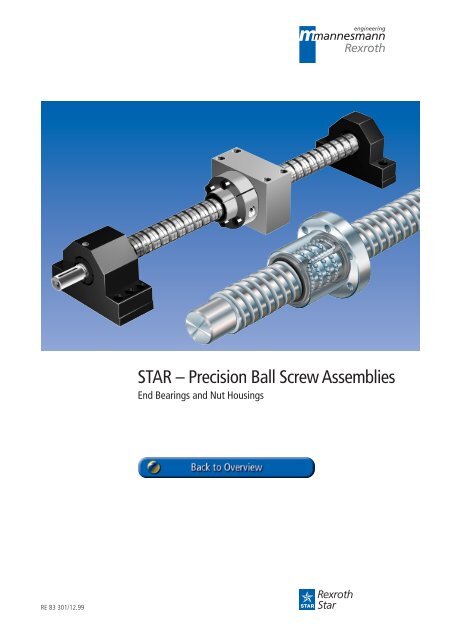
<strong>STAR</strong> <strong>–</strong> <strong>Precision</strong> <strong>Ball</strong> <strong>Screw</strong> <strong>Assemblies</strong><br />
End Bearings and Nut Housings
<strong>STAR</strong> <strong>–</strong> Linear Motion Technology<br />
<strong>Ball</strong> Rail Systems Standard Rail Systems<br />
Rail Systems with Aluminium Runner Blocks<br />
Super Rail Systems<br />
Wide Rail Systems<br />
Supplementary Parts<br />
Roller Rail Systems<br />
Miniature Rail Systems<br />
Cam Roller Guides<br />
Linear Bushings and Shafts Linear Bushings<br />
Linear Sets<br />
Shafts<br />
Shaft Support Rails<br />
Shaft Support Blocks<br />
<strong>Ball</strong> Transfer Units<br />
<strong>Precision</strong> <strong>Ball</strong> <strong>Screw</strong> <strong>Assemblies</strong><br />
Other Engineering Components<br />
Linear Motion Systems Linear Motion Slides + <strong>Ball</strong> <strong>Screw</strong><br />
+ Toothed Belt<br />
Linear Modules<br />
Compact Modules<br />
<strong>Ball</strong> Rail Tables<br />
+ <strong>Ball</strong> <strong>Screw</strong><br />
+ Toothed Belt<br />
+ Gear Rack<br />
+ Linear Motor<br />
+ Pneumatic Drive<br />
+ <strong>Ball</strong> <strong>Screw</strong><br />
+ <strong>Ball</strong> <strong>Screw</strong><br />
+ Linear Motor<br />
ALU-<strong>STAR</strong> Profile System<br />
Controllers, Motors, Electrical Accessories,<br />
Electric Cylinders<br />
2 RE 83 301/12.99
<strong>STAR</strong> <strong>–</strong> <strong>Precision</strong> <strong>Ball</strong> <strong>Screw</strong> <strong>Assemblies</strong><br />
Product Overview 4<br />
Application Examples 10<br />
Inquiries and Orders 12<br />
Dimension Tables 18<br />
<strong>–</strong> Nuts 18<br />
<strong>–</strong> Nut Housings 32<br />
<strong>–</strong> <strong>Screw</strong>s 36<br />
<strong>–</strong> End Machining Details 40<br />
<strong>–</strong> Pillow block units 62<br />
<strong>–</strong> Bearings 70<br />
<strong>–</strong> Slotted Nuts and Housing Nuts 76<br />
General 78<br />
Acceptance Conditions and Tolerance Grades 80<br />
Preload and Rigidity 84<br />
Mounting 90<br />
Lubrication 92<br />
Design Calculations 94<br />
End Bearings, Design Notes, Mounting Instructions 98<br />
End Bearings, Design Calculations 100<br />
Design Calculation Service Form 102<br />
Inquiry / Order Form 103<br />
RE 83 301/12.99 3
<strong>STAR</strong> <strong>–</strong> <strong>Precision</strong> <strong>Ball</strong> <strong>Screw</strong> <strong>Assemblies</strong><br />
Product Overview<br />
Nuts for precision-rolled and<br />
ground-thread screws<br />
Single nut with flange<br />
DIN 69 051, T.5<br />
FEM-E-C<br />
Adjustable-preload<br />
single nut DIN 69 051, T.5<br />
SEM-E-C<br />
Single nut with flange<br />
FEM-E-S<br />
Adjustable-preload<br />
single nut SEM-E-S<br />
Cylindrical single nut<br />
ZEM-E-S<br />
Double nut with flange<br />
DIN 69 051, T.5<br />
FDM-E-C<br />
Double nut with flange<br />
FDM-E-S<br />
<strong>Precision</strong> <strong>Screw</strong>s<br />
<strong>Precision</strong>-rolled screw<br />
Tolerance grades<br />
T5, T7, T9,<br />
(P5)<br />
Ground-thread screws<br />
Tolerance grades<br />
P1, P3, P5<br />
Page<br />
18<br />
20<br />
22<br />
24<br />
26<br />
28<br />
30<br />
36<br />
38<br />
Diameter d 0<br />
8<br />
12<br />
16<br />
20<br />
25<br />
32<br />
40<br />
50<br />
63<br />
80<br />
100<br />
125<br />
2.5<br />
d0 x P<br />
8 x 2.5<br />
12 x 5, 10<br />
16 x 5, 10, 16<br />
20 x 5, 20<br />
25 x 5, 10, 25<br />
32 x 5, 10, 20, 32<br />
40 x 5 / 50 x 5<br />
40 x 10, 12, 16, 20, 40<br />
50 x 10, 12, 16, 20, 40<br />
63 x 10, 20, 40<br />
80 x 10, 20<br />
Lead P<br />
5 10 12 16 20 25 32 40<br />
Single nut Double nut<br />
1500 2500 4500 5000 7500<br />
Maximum length<br />
standard, available at short notice available upon request<br />
d 0 x P<br />
(mm)<br />
1500 3000 5000 8000<br />
1000 1200<br />
8 x 2.5<br />
12 x 5, 10<br />
16 x 5, 10, 16<br />
20 x 5, 20<br />
25 x 5, 10, 25<br />
32 x 5, 10, 20, 32<br />
40 x 5 / 50 x 5<br />
40 x 10, 12, 16, 20, 40<br />
50 x 10, 12, 16, 20, 40<br />
63 x 10, 20, 40<br />
80 x 10, 20<br />
100 x 10, 20<br />
125 x 10, 20<br />
(mm)<br />
800 4000<br />
Maximum length<br />
standard, available at short notice available upon request<br />
4 RE 83 301/12.99
End machining details<br />
Bearings<br />
LAF<br />
LAN<br />
LAD<br />
Pillow block units<br />
SEA-F<br />
SEA-L<br />
SEB-F<br />
SEB-L<br />
Nut housings<br />
MGS<br />
for FEM-E-S<br />
FDM-E-S<br />
SEM-E-S<br />
MGD<br />
for FEM-E-C<br />
FDM-E-C<br />
SEM-E-C<br />
Slotted nuts NMA and NMZ<br />
as single parts<br />
Housing nut GR<br />
Page<br />
RE 83 301/12.99 5<br />
40<br />
70<br />
72<br />
74<br />
62<br />
64<br />
66<br />
68<br />
32<br />
34<br />
76<br />
77<br />
Diameter d 0<br />
Diameter d 0<br />
Diameter d 0<br />
Diameter d 0<br />
8<br />
12<br />
16<br />
20<br />
25<br />
32<br />
40<br />
50<br />
63<br />
80<br />
8<br />
12<br />
16<br />
20<br />
25<br />
32<br />
40<br />
50<br />
63<br />
80<br />
8<br />
12<br />
16<br />
20<br />
25<br />
32<br />
40<br />
2.5<br />
2.5<br />
LAF<br />
2.5<br />
SEA-F<br />
SEA-L<br />
2.5<br />
16<br />
20<br />
25<br />
32<br />
40<br />
50<br />
63<br />
80<br />
5 10 12<br />
Lead P<br />
16 20 25 32 40<br />
5 10 12<br />
Lead P<br />
16 20 25 32 40<br />
5 10 12<br />
Lead P<br />
16 20 25 32 40<br />
SEB-F<br />
SEB-L<br />
5 10 12<br />
Lead P<br />
16 20 25 32 40<br />
MGD MGS<br />
LAN / LAD
<strong>STAR</strong> <strong>–</strong> <strong>Precision</strong> <strong>Ball</strong> <strong>Screw</strong> <strong>Assemblies</strong><br />
Product Overview<br />
As simple as it is to describe<br />
the elementary function of a<br />
precision ball screw assembly,<br />
in practice you are faced with<br />
variety of types and applications.<br />
Affordable system design is now<br />
easier then ever:<br />
New products have made the<br />
catalogue grow in size.<br />
On the following pages you will find<br />
the various elements for you to<br />
choose from, complete with order<br />
specifications and examples.<br />
A further new development is the<br />
WINKGT calculation software<br />
for designing and calculating<br />
precision ball screw assemblies.<br />
Written to run under the Windows<br />
NT operating system, it is available<br />
on CD-ROM for you to perform your<br />
own calculations.<br />
Alternatively, you can arrange for<br />
Rexroth <strong>STAR</strong> to produce a design<br />
calculation on your behalf. To do so,<br />
simply complete and return the<br />
inquiry form, ! see “Inquiry /<br />
Order Form”, on page 103.<br />
For over 20 years, <strong>Precision</strong><br />
<strong>Ball</strong> <strong>Screw</strong> <strong>Assemblies</strong> have<br />
been a core product group<br />
within the <strong>STAR</strong> range.<br />
The related standards<br />
(DIN 69 051 and ISO 3408) are<br />
fully supported by Rexroth<br />
<strong>STAR</strong>. For every <strong>STAR</strong> nut with<br />
flange in this catalog you will<br />
therefore find a corresponding<br />
design with DIN mounting<br />
dimensions.<br />
<strong>STAR</strong> <strong>–</strong> <strong>Precision</strong> <strong>Ball</strong> <strong>Screw</strong> <strong>Assemblies</strong><br />
provide technical designers<br />
with diverse solutions for positioning<br />
and transport tasks:<br />
<strong>–</strong> complete ball screw assemblies<br />
with precision-rolled or ground<br />
thread screws combined with any<br />
of the available single or double<br />
nuts<br />
<strong>–</strong> precision-rolled screws of optional<br />
length, with soft-annealed<br />
ends and ground-thread ECO<br />
screws in grid lengths for end<br />
machining by the customer<br />
<strong>–</strong> single nuts supplied on a<br />
mounting tube; all single nuts in<br />
the version with reduced<br />
backlash can be easily mounted<br />
by the customer. In addition, the<br />
adjustable-preload single nut<br />
allows the customer to perform<br />
preload adjustment in-house.<br />
<strong>–</strong> matching nut housings and end<br />
bearings<br />
<strong>Precision</strong>-rolled screws are manufactured<br />
independently of customers<br />
orders. Our large world-wide stocks<br />
guarantee a fast response. Availability<br />
is one advantage, low prices<br />
another.<br />
To perform particularly demanding<br />
positioning tasks we have developed<br />
a measuring system for<br />
integration in the rails of ball and<br />
roller rail systems (Catalog<br />
R.82 350). The linear measuring<br />
system in the rail then replaces the<br />
positioning information in the ball<br />
screw. This way we are able to<br />
achieve a maximum of flexibility in<br />
design and a maximum of precision<br />
in operation. Each nut is manufactured<br />
with the same technology,<br />
enabling it to be used in the<br />
high-precision range too.<br />
Nuts are available ex<br />
stock from a large<br />
cataloged range<br />
covering different<br />
mounting dimensions<br />
and technical details.<br />
6 RE 83 301/12.99
Short nut length<br />
Available ex stock<br />
High load-carrying capacity<br />
due to large number of recirculating<br />
balls<br />
Smooth outer shell, consistently<br />
smooth operation due to internal<br />
ball recirculation system<br />
RE 83 301/12.99 7<br />
Particularly smooth motion due to the tangential<br />
lift-off of the balls from the raceway within a<br />
single, fully enclosed ball circuit in the nut<br />
Effective wiping sealing<br />
No protruding parts,<br />
nut is easily mounted<br />
Adjustable-preload single nut
<strong>STAR</strong> <strong>–</strong> <strong>Precision</strong> <strong>Ball</strong> <strong>Screw</strong> <strong>Assemblies</strong><br />
Product Overview<br />
<strong>STAR</strong> <strong>–</strong> <strong>Precision</strong> <strong>Ball</strong> <strong>Screw</strong><br />
<strong>Assemblies</strong> with end bearings<br />
<strong>STAR</strong> <strong>–</strong> <strong>Precision</strong> <strong>Ball</strong> <strong>Screw</strong> <strong>Assemblies</strong><br />
are available with various fixed<br />
and floating bearing units complete<br />
with matching slotted nuts.<br />
<strong>STAR</strong> precision pillow block units to<br />
match the bearings enable:<br />
<strong>–</strong> Easy installation due to the<br />
variable of fixture options and<br />
reference edges<br />
<strong>–</strong> Use of premachined pin holes<br />
provides increased mounting<br />
accuracy<br />
SEA units were recently added to<br />
supplement the range of pillow<br />
block units.<br />
<strong>STAR</strong> <strong>–</strong> <strong>Precision</strong> <strong>Ball</strong> <strong>Screw</strong><br />
<strong>Assemblies</strong> with nut housing<br />
Housings for various flanged nuts<br />
complete the ready-to-mount <strong>STAR</strong><br />
product range.<br />
Lubricated for life<br />
Available ex stock<br />
Reference edge<br />
8 RE 83 301/12.99
High axial load capacity<br />
Low friction<br />
RE 83 301/12.99 9<br />
High rigidity<br />
Definition of a precision ball<br />
screw assembly<br />
DIN 69 051, Part 1 defines a ball<br />
screw as follows:<br />
An assembly comprising a ball<br />
screw shaft and a ball nut which is<br />
capable of converting rotary motion<br />
into linear motion vice versa. The<br />
rolling elements of the assembly are<br />
balls.<br />
It is used to convert a rotary movement<br />
into a linear movement or vice<br />
versa.
<strong>STAR</strong> <strong>–</strong> <strong>Precision</strong> <strong>Ball</strong> <strong>Screw</strong> <strong>Assemblies</strong><br />
Application Examples<br />
<strong>STAR</strong> <strong>–</strong> <strong>Precision</strong> <strong>Ball</strong> <strong>Screw</strong><br />
<strong>Assemblies</strong> have been successfully<br />
implemented worldwide<br />
in the following areas:<br />
<strong>–</strong> Cutting machine tools<br />
<strong>–</strong> Forming machine tools<br />
<strong>–</strong> Automation and handling<br />
<strong>–</strong> Woodworking<br />
<strong>–</strong> Electrical and electronics<br />
<strong>–</strong> Printing and paper<br />
<strong>–</strong> Injection molding machines<br />
<strong>–</strong> Food and packaging industry<br />
<strong>–</strong> Medical equipment<br />
<strong>–</strong> Textile industry<br />
<strong>–</strong> etc.<br />
Machining center<br />
Actuator<br />
10 RE 83 301/12.99
RE 83 301/12.99 11<br />
Folding press<br />
Lathe
<strong>STAR</strong> <strong>–</strong> <strong>Precision</strong> <strong>Ball</strong> <strong>Screw</strong> <strong>Assemblies</strong><br />
Inquiries and Orders<br />
A special feature of this new catalog<br />
edition is a new system of order code.<br />
All nuts, screws and end machining details<br />
can now be defined with the order code.<br />
We have taken account of all former<br />
selection criteria as well as adding new<br />
ones. The diversity of possible combinations<br />
is limitless.<br />
Attention is focused in particular on the<br />
definition of end machining details. For<br />
many design versions there is a prepared<br />
definition, providing you with a suitable<br />
solution for practically every application.<br />
If you wish to send us an inquiry, simply<br />
complete the last page of the catalog.<br />
If no drawing is available yet, please<br />
specify your wishes using the variable<br />
order code in the structure stipulated.<br />
Should you already have a drawing<br />
available as a CAD file (in Pro/E20,<br />
AutoCAD/Genius 14 or DXF formats), you<br />
can send us the data by e-mail (see the<br />
back cover of the catalog for our e-mail<br />
address).<br />
If the drawing exists on paper only, you<br />
can of course send it to us by conventional<br />
mail.<br />
Each customer-specific precision ball screw<br />
assembly is issued with an ID number<br />
when an order is placed. If you have any<br />
subsequent queries, you need only quote<br />
this ID number.<br />
Nominal diameters, leads<br />
Nominal diameter d 0<br />
8<br />
12<br />
16<br />
20<br />
25<br />
32<br />
40<br />
50<br />
63<br />
80<br />
Overall lengths<br />
2.5<br />
5 10 12<br />
Lead P<br />
16 20 25 32 40<br />
<strong>Precision</strong>-ground screws > ∅ 80 mm available upon request<br />
Overall length<br />
12 RE 83 301/12.99
Nut types<br />
All nuts can be combined with all screws and all end machining<br />
options. The various versions and forms are shown below.<br />
Single nut with flange<br />
1502-DIN 69 051, T.5<br />
FEM-E-C<br />
Adjustable-preload<br />
single nut, 1512-DIN 69 051,<br />
T.5 SEM-E-C<br />
Cylindrical single nut<br />
1512-/1532-<br />
ZEM-E-S<br />
Double nut with flange<br />
1502-DIN 69 051, T.5<br />
FDM-E-C<br />
Single nut with flange<br />
1502-/1512-/1532-<br />
FEM-E-S<br />
Page 18 Page 22<br />
Adjustable-preload<br />
single nut, 1512-/1532-/1552-<br />
SEM-E-S<br />
Page 20 Page 24<br />
Page 26<br />
Double nut with flange<br />
1502- FDM-E-S<br />
Page 28 Page 30<br />
RE 83 301/12.99 13<br />
Mounting direction of nut types<br />
The following four drawings show the position of the left and<br />
right screw end.<br />
Centering diameter D 1<br />
Centering diameter D 1<br />
Lube port<br />
Centering diameter D 1<br />
N.B.: The centering diameter on a nut with flange and the lube<br />
port on a cylindrical nut points to the right end of<br />
the screw.
<strong>STAR</strong> <strong>–</strong> <strong>Precision</strong> <strong>Ball</strong> <strong>Screw</strong> <strong>Assemblies</strong><br />
Inquiries and Orders<br />
<strong>Screw</strong> ends, forms for a left or right screw end<br />
00<br />
01<br />
11<br />
21<br />
31<br />
41<br />
51<br />
61<br />
71<br />
81<br />
91<br />
Basic version with keyway annealed<br />
Not annealed<br />
Page 41<br />
Page 42<br />
Page 44<br />
Page 46<br />
Page 48<br />
Page 50<br />
Page 52<br />
Page 54<br />
Page 56<br />
Page 58<br />
Page 60<br />
02<br />
12<br />
62<br />
72<br />
82<br />
92<br />
Page 42<br />
Page 44<br />
Page 54<br />
Page 56<br />
Page 58<br />
Page 60<br />
Machining of end face Z centering hole DIN 332-D S hex socket<br />
99<br />
53<br />
83<br />
93<br />
annealed Page 40<br />
End friction welded, only 8 x 2.5R<br />
Page 52<br />
Page 58<br />
Page 60<br />
14 RE 83 301/12.99
Order Code<br />
<strong>Precision</strong> <strong>Ball</strong> <strong>Screw</strong> Assembly<br />
<strong>Screw</strong><br />
Nut type<br />
FEM-E-C Single nut with flange to DIN 69 051, Part 5<br />
FEM-E-S Single nut with flange of <strong>STAR</strong> form<br />
SEM-E-C Adjustable-preload single nut to DIN 69 051, Part 5<br />
SEM-E-S Adjustable-preload single nut of <strong>STAR</strong> form<br />
ZEM-E-S Cylindrical single nut of <strong>STAR</strong> form<br />
FDM-E-C Double nut with flange to DIN 69 051, Part 5<br />
FDM-E-S Double nut with flange of <strong>STAR</strong> form<br />
Size Nominal diameter (mm)<br />
Lead (mm)<br />
Direction of lead R … right, L … left<br />
<strong>Ball</strong> diameter (mm)<br />
Number of ball track turns in the nut<br />
Seal<br />
Preload<br />
<strong>Precision</strong><br />
<strong>Screw</strong><br />
Left screw end<br />
Right screw end<br />
Overall length (mm)<br />
Documentation<br />
Lubrication<br />
0 … none 2*… reinforced seal<br />
1 … standard seal X … not possible<br />
0 … standard backlash 4 … 10% (double nut)<br />
1 … reduced backlash 5 … 7% (double nut)<br />
2**… 5% (single nut) X … not possible<br />
3 … 2% (single nut) standard<br />
P1 P3 P5 ground-thread screw<br />
(P5) T5 T7 T9 precision-rolled screw<br />
R … precision-rolled S … ground-thread<br />
Form<br />
Z … centering to DIN 332-D<br />
Option S … hex socket<br />
K …none<br />
Version<br />
see left screw end<br />
RE 83 301/12.99 15<br />
SEM-E-S 20 x 5R x 3-4 1 2 T7 R 81Z120 41Z120 1250 1 1<br />
S 20 x 5R x 3 X X T7 R 81Z120 41Z120 1250 1 0<br />
0 … standard (acceptance test reportl) 2 … torque test report<br />
-is always supplied<br />
1 … lead test report<br />
3 … lead and torque test report<br />
0 … Preserved 1 … Preserved and nut with basic grease<br />
* only for d0 25 to 40 of the precision-rolled version; note higher frictional torque!<br />
** only for d0 16 to 63<br />
N.B.: It is also possible, to process inquiries based on a customer's drawings.
<strong>STAR</strong> <strong>–</strong> <strong>Precision</strong> <strong>Ball</strong> <strong>Screw</strong> <strong>Assemblies</strong><br />
Inquiries and Orders - Specias Cases<br />
<strong>Screw</strong> with annealed ends<br />
For machining of screw ends by the<br />
customer.<br />
<strong>Screw</strong><br />
<strong>Screw</strong><br />
Size<br />
<strong>Precision</strong><br />
<strong>Screw</strong>: R…rolled<br />
left screw end Form<br />
Option K…none<br />
Annealed length (mm)<br />
right screw end<br />
Overall length (mm)<br />
see left screw end<br />
Documentation: 0, 1 … see page 15<br />
Lubrication: 0 … Preserved<br />
150 annealed 80 annealed<br />
1250 overall length<br />
S 20 x 5R x 3 X X T7 R 99 K150 99K080 1250 1 0<br />
16 RE 83 301/12.99
<strong>Ball</strong> screw with annealed ends<br />
For machining of the screw ends by<br />
the customer.<br />
Nut with preload<br />
The nut is delivered already mounted. A<br />
mounting tube is supplied for dismantling.<br />
Nut without preload<br />
The nut and screw are delivered<br />
unassembled.<br />
<strong>Ball</strong> screw<br />
Nut type<br />
Size<br />
Seal<br />
Preload<br />
<strong>Precision</strong><br />
<strong>Screw</strong>: R…rolled<br />
150 annealed<br />
RE 83 301/12.99 17<br />
1250 overall length<br />
Centering diameter D 1<br />
80 annealed and<br />
machine-faced to<br />
core diameter<br />
Mounting direction<br />
N.B.: The centering diameter (or lube port on a cylindrical nut) points to the<br />
machine-faced, right-hand end of the screw. The shorter screw end is<br />
machine-faced to core diameter for mounting reasons.<br />
FEM-E-S 20 x 5R x 3-4 1 2 T7 R 99 K150 99K080 1250 1 1<br />
Left screw end Form<br />
Option K…none<br />
Annealed length (mm)<br />
Right screw<br />
Overall length (mm)<br />
see left screw end<br />
Documentation: 0, 1, 2, 3 … see Page 15<br />
Lubrication: 0 … Preserved 1 … Preserved and nut with basic grease
<strong>STAR</strong> <strong>–</strong> <strong>Precision</strong> <strong>Ball</strong> <strong>Screw</strong> <strong>Assemblies</strong><br />
Single Nut with Flange FEM-E-C<br />
Mounting dimensions to<br />
DIN 69 051, Part 5<br />
Flange type C<br />
d 0 = nominal diameter<br />
P = Lead<br />
(R = right-hand, L = left-hand)<br />
DW = ball diameter<br />
i = number of ball track turns<br />
Order code:<br />
FEM-E-C 20 x 5R x 3-4 1 2 T7 R 82Z120 41Z120 1250 1 0<br />
Size Part number Load ratings<br />
dyn. stat.<br />
d0 x P x Dw - i C<br />
(N)<br />
C0 (N)<br />
16 x 5R x 3 - 4 1502-0-1065 12300 16100<br />
16 x 10R x 3 - 3 1502-0-4085 9600 12300<br />
16 x 16R x 3 - 3 1502-0-6065 9300 12000<br />
20 x 5R x 3 - 4 1502-1-1085 14300 21500<br />
20 x 20R x 3.5 - 3 1502-1-7065 13300 18800<br />
25 x 5R x 3 - 4 1502-2-1085 15900 27200<br />
25 x 10R x 3 - 4 1502-2-4085 15700 27000<br />
25 x 25R x 3.5 - 3 1502-2-8065 14700 23300<br />
32 x 5R x 3.5 - 4 1502-3-1085 21600 40000<br />
32 x 10R x 3.969 - 5 1502-3-4086 31700 58300<br />
32 x 20R x 3.969 - 3 1502-3-7065 19700 33700<br />
32 x 32R x 3.969 - 3 1502-3-9065 19500 34000<br />
40 x 5R x 3.5 - 5 1502-4-1086 29100 64100<br />
40 x 10R x 6 - 4 1502-4-4085 50000 86400<br />
40 x 12R x 6 - 4 1502-4-5065 49900 86200<br />
40 x 16R x 6 - 4 1502-4-6065 49700 85900<br />
40 x 20R x 6 - 3 1502-4-7085 37900 62800<br />
40 x 40R x 6 - 3 1502-4-9065 37000 62300<br />
50 x 5R x 3.5 - 5 1502-5-1086 32000 81300<br />
50 x 10R x 6 - 6 1502-5-4086 79700 166500<br />
50 x 12R x 6 - 6 1502-5-5066 79600 166400<br />
50 x 16R x 6 - 6 1502-5-6066 79400 166000<br />
50 x 20R x 6.5 - 5 1502-5-7086 75700 149700<br />
50 x 40R x 6.5 - 3 1502-5-9065 46500 85900<br />
63 x 10R x 6 - 6 1502-6-4086 88800 214300<br />
63 x 20R x 6.5 - 5 1502-6-7086 83900 190300<br />
63 x 40R x 6.5 - 3 1502-6-9065 53400 114100<br />
80 x 10R x 6.5 - 6 1502-7-4086 108400 291700<br />
80 x 20R x 9 - 6 1502-7-7086 170900 403900<br />
80 x 20R x 12.7 - 6 1502-7-7066 262700 534200<br />
100 x 10R x 6.5 - 6 1502-8-4066 119500 371900<br />
100 x 20R x 12.7 - 6 1502-8-7066 295100 686400<br />
125 x 10R x 6.5 - 6 1502-9-4066 130600 468700<br />
125 x 20R x 12.7 - 6 1502-9-7066 326500 870400<br />
18 RE 83 301/12.99
D 5<br />
Lube port at flange center<br />
L 3<br />
RE 83 301/12.99 19<br />
D 1<br />
L 4<br />
Dw<br />
L 10<br />
L<br />
-0.05<br />
D1 -0.1<br />
d1<br />
d2<br />
N.B.: On a precision-ground screw the core diameter<br />
d 2 is smaller by max. 0.3 mm due to the root<br />
undercut<br />
d 0<br />
90°<br />
90°<br />
30°<br />
D 7<br />
D 7<br />
d 0 ≤ 32<br />
d 0 ≥ 40<br />
Dimensions (mm) Weight<br />
d1 d2 D1 g6<br />
D5 Hole<br />
pattern<br />
D6 D7 L L3L4 L9 L10 S m<br />
(kg)<br />
15.0 12.9 28 48 BB2 38 5.5 38 12 10 44.0 26 M6 0.19<br />
15.0 12.9 28 48 BB2 38 5.5 45 12 16 44.0 33 M6 0.21<br />
15.0 12.9 28 48 BB2 38 5.5 61 12 20 44.0 49 M6 0.26<br />
19.0 16.9 36 58 BB2 47 6.6 40 12 10 51.0 28 M6 0.31<br />
19.3 16.7 36 58 BB2 47 6.6 77 12 25 51.0 65 M6 0.49<br />
24.0 21.9 40 62 BB2 51 6.6 45 12 10 55.0 33 M6 0.36<br />
24.0 21.9 40 62 BB2 51 6.6 64 12 20 55.0 52 M6 0.47<br />
24.0 21.4 40 62 BB2 51 6.6 95 12 30 55.0 83 M6 0.63<br />
31.0 28.4 50 80 BB2 65 9.0 48 13 10 71.0 35 M6 0.62<br />
31.0 27.9 50 80 BB2 65 9.0 77 13 16 71.0 64 M6 0.84<br />
31.0 27.9 50 80 BB2 65 9.0 84 13 25 71.0 71 M6 0.90<br />
31.0 27.9 50 80 BB2 65 9.0 120 13 40 71.0 107 M6 1.21<br />
39.0 36.4 63 93 BB1 78 9.0 54 15 10 81.5 39 M8x1 1.03<br />
38.0 33.8 63 93 BB1 78 9.0 70 15 16 81.5 55 M8x1 1.19<br />
38.0 33.8 63 93 BB1 78 9.0 75 15 25 81.5 60 M8x1 1.27<br />
38.0 33.8 63 93 BB1 78 9.0 90 15 25 81.5 75 M8x1 1.51<br />
38.0 33.8 63 93 BB1 78 9.0 88 15 40 81.5 73 M8x1 1.44<br />
38.0 33.8 63 93 BB1 78 9.0 142 15 45 81.5 127 M8x1 2.16<br />
49.0 46.4 75 110 BB1 93 11.0 54 15 10 97.5 39 M8x1 1.39<br />
48.0 43.8 75 110 BB1 93 11.0 90 18 16 97.5 72 M8x1 2.14<br />
48.0 43.8 75 110 BB1 93 11.0 105 18 25 97.5 87 M8x1 2.38<br />
48.0 43.8 75 110 BB1 93 11.0 128 18 25 97.5 110 M8x1 2.75<br />
48.0 43.4 75 110 BB1 93 11.0 132 18 25 97.5 114 M8x1 2.73<br />
48.0 43.4 75 110 BB1 93 11.0 149 18 45 97.5 131 M8x1 3.04<br />
61.0 56.8 90 125 BB1 108 11.0 90 22 16 110.0 68 M8x1 2.56<br />
61.0 56.4 95 135 BB1 115 13.5 132 22 25 117.5 110 M8x1 4.51<br />
61.0 56.4 95 135 BB1 115 13.5 149 22 45 117.5 127 M8x1 5.04<br />
78.0 73.3 105 145 BB1 125 13.5 95 22 16 127.5 73 M8x1 3.40<br />
77.0 70.8 125 165 BB1 145 13.5 160 25 25 147.5 135 M8x1 9.95<br />
76.0 67.0 125 165 BB1 145 13.5 170 25 25 147.5 145 M8x1 10.20<br />
98.0 93.4 125 165 BB1 145 13.5 95 25 16 147.5 70 M8x1 4.40<br />
96.0 87.1 150 202 BB1 176 17.5 170 30 25 178.5 140 M8x1 14.30<br />
123.0 118.0 150 202 BB1 176 17.5 95 25 16 178.5 70 M8x1 5.65<br />
121.0 112.0 170 222 BB1 196 17.5 170 40 25 198.5 130 M8x1 16.10<br />
S<br />
S<br />
D 6<br />
D 6<br />
30°<br />
22.5°<br />
L 9<br />
L 9<br />
BB2<br />
BB1
<strong>STAR</strong> <strong>–</strong> <strong>Precision</strong> <strong>Ball</strong> <strong>Screw</strong> <strong>Assemblies</strong><br />
Adjustable-Preload Single Nut SEM-E-C<br />
Mounting dimensions to<br />
DIN 69 051, Part 5<br />
Flange type C<br />
d0 = nominal diameter<br />
P = lead<br />
(R = right-hand, L = left-hand)<br />
DW = ball diameter<br />
i = number of ball track turns<br />
Order code:<br />
SEM-E-C 20 x 5R x 3-4 1 2 T7 R 82Z120 41Z120 1250 1 0<br />
Size Part number Load ratings<br />
dyn. stat.<br />
d0 x P x Dw - i C<br />
(N)<br />
C0 (N)<br />
16 x 5R x 3 - 4 1512-0-1055 12300 16100<br />
16 x 10R x 3 - 3 1512-0-4075 9600 12300<br />
16 x 16R x 3 - 3 1512-0-6055 9300 12000<br />
20 x 5R x 3 - 4 1512-1-1075 14300 21500<br />
20 x 20R x 3.5 - 3 1512-1-7055 13300 18800<br />
25 x 5R x 3 - 4 1512-2-1075 15900 27200<br />
25 x 10R x 3 - 4 1512-2-4075 15700 27000<br />
25 x 25R x 3.5 - 3 1512-2-8055 14700 23300<br />
32 x 5R x 3.5 - 4 1512-3-1075 21600 40000<br />
32 x 10R x 3.969 - 5 1512-3-4075 31700 58300<br />
32 x 20R x 3.969 - 3 1512-3-7055 19700 33700<br />
32 x 32R x 3.969 - 3 1512-3-9055 19500 34000<br />
40 x 5R x 3.5 - 5 1512-4-1075 29100 64100<br />
40 x 10R x 6 - 4 1512-4-4075 50000 86400<br />
40 x 12R x 6 - 4 1512-4-5055 49900 86200<br />
40 x 20R x 6 - 3 1512-4-7075 37900 62800<br />
40 x 40R x 6 - 3 1512-4-9055 37000 62300<br />
50 x 5R x 3.5 - 5 1512-5-1075 32000 81300<br />
50 x 10R x 6 - 6 1512-5-4075 79700 166500<br />
50 x 12R x 6 - 6 1512-5-5055 79600 166400<br />
50 x 20R x 6.5 - 5 1512-5-7076 75700 149700<br />
50 x 40R x 6.5 - 3 1512-5-9055 46500 85900<br />
63 x 10R x 6 - 6 1512-6-4075 88800 214300<br />
63 x 20R x 6.5 - 5 1512-6-7076 83900 190300<br />
63 x 40R x 6.5 - 3 1512-6-9055 53400 114100<br />
80 x 10R x 6.5 - 6 1512-7-4075 108400 291700<br />
80 x 20R x 9 - 6 1512-7-7075 170900 403900<br />
80 x 20R x 12.7 - 6 1512-7-7055 262700 534200<br />
20 RE 83 301/12.99
D 5<br />
D 1<br />
+0.7<br />
L 5<br />
L 3<br />
L<br />
N.B.: On a precision-ground screw<br />
the core diameter d 2 is smaller<br />
by max. 0.3 mm due to the<br />
root undercut.<br />
RE 83 301/12.99 21<br />
Dw<br />
L 8<br />
1<br />
D<br />
L 10<br />
L 4<br />
d2<br />
d1<br />
d0 -0.05<br />
-0.1<br />
D 1<br />
d 0 ≤ 32<br />
d 0 ≥ 40<br />
Dimensions (mm) Weight<br />
d 1 d 2 D 1 D 5 Hole D 6 D 7 L L 3 L 4 L 5 L 9 L 10 S L 8 m<br />
f9 pattern (Kg)<br />
15.0 12.9 28 48 BB2 38 5.5 38 15 10 11.5 44 11.5 M6 7.1 0.20<br />
15.0 12.9 28 48 BB2 38 5.5 45 15 15 15 44 15 M6 11 0.22<br />
15.0 12.9 28 48 BB2 38 5.5 61 15 20 23 44 23 M6 10 0.29<br />
19.0 16.9 36 58 BB2 47 6.6 40 15 10 12.5 51 12.5 M6 7.1 0.33<br />
19.3 16.7 36 58 BB2 47 6.6 77 20 25 28.5 51 28.5 M6 12.5 0.56<br />
24.0 21.9 40 62 BB2 51 6.6 45 20 10 12.5 55 12.5 M6 9.5 0.43<br />
24.0 21.9 40 62 BB2 51 6.6 64 20 16 22 55 22 M6 10 0.54<br />
24.0 21.4 40 62 BB2 51 6.6 95 25 30 35 55 35 M6 14 0.77<br />
31.0 28.4 50 80 BB2 65 9 48 20 10 14 71 14 M6 9.7 0.74<br />
31.0 27.9 50 80 BB2 65 9 77 20 16 28.5 71 28.5 M6 12.5 0.97<br />
31.0 27.9 50 80 BB2 65 9 84 20 25 32 71 32 M6 12.5 1.04<br />
31.0 27.9 50 80 BB2 65 9 120 20 40 50 71 50 M6 12.5 1.34<br />
39.0 36.4 63 93 BB1 78 9 54 25 10 14.5 81.5 14.5 M8x1 12 1.25<br />
38.0 33.8 63 93 BB1 78 9 70 25 16 22.5 81.5 22.5 M8x1 11.8 1.39<br />
38.0 33.8 63 93 BB1 78 9 75 25 25 25 81.5 25 M8x1 12.5 1.47<br />
38.0 33.8 63 93 BB1 78 9 88 25 25 31.5 81.5 31.5 M8x1 16.5 1.55<br />
38.0 33.8 63 93 BB1 78 9 142 40 45 51 81.5 51 M8x1 25 2.69<br />
49.0 46.4 75 110 BB1 93 11 54 25 10 14.5 97.5 14.5 M8x1 12 1.67<br />
48.0 43.8 75 110 BB1 93 11 90 30 16 30 97.5 30 M8x1 14.1 2.46<br />
48.0 43.8 75 110 BB1 93 11 105 30 25 37.5 97.5 37.5 M8x1 15 2.69<br />
48.0 43.4 75 110 BB1 93 11 132 30 25 51 97.5 51 M8x1 20 3.08<br />
48.0 43.4 75 110 BB1 93 11 149 30 45 59.5 97.5 59.5 M8x1 18 3.39<br />
61.0 56.8 90 125 BB1 108 11 90 30 16 30 110 30 M8x1 14 2.83<br />
61.0 56.4 95 135 BB1 115 13.5 132 30 25 51 117.5 51 M8x1 20 4.86<br />
61.0 56.4 95 135 BB1 115 13.5 149 30 45 59.5 117.5 59.5 M8x1 18 5.36<br />
78.0 73.3 105 145 BB1 125 13.5 95 30 16 32.5 127.5 32.5 M8x1 14 3.73<br />
77.0 70.8 125 165 BB1 145 13.5 160 50 25 55 147.5 55 M8x1 23.5 10.88<br />
76.0 67.0 125 165 BB1 145 13.5 170 50 25 60 147.5 60 M8x1 23.7 13.50<br />
90°<br />
30°<br />
90°<br />
D 7<br />
D 7<br />
S<br />
S<br />
D 6<br />
D 6<br />
22.5°<br />
30°<br />
L 9<br />
L 9<br />
BB2<br />
BB1
<strong>STAR</strong> <strong>–</strong> <strong>Precision</strong> <strong>Ball</strong> <strong>Screw</strong> <strong>Assemblies</strong><br />
Single Nut with Flange FEM-E-S<br />
<strong>STAR</strong> mounting dimensions<br />
d0 = nominal diameter<br />
P = lead<br />
(R = right-hand, L = left-hand)<br />
DW = ball diameter<br />
i = number of ball track turns<br />
Order code:<br />
FEM-E-S 20 x 5R x 3-4 1 2 T7 R 82Z120 41Z120 1250 1 0<br />
Size Part number Load ratings<br />
dyn. stat.<br />
d0 x P x Dw - i C<br />
(N)<br />
C0 (N)<br />
8 x 2.5R x 1.588 - 3 1532-2-3003 2200 2800<br />
12 x 5R x 2 - 3 1532-4-6023 3800 5800<br />
12 x 10R x 2 - 2 1532-4-9013 2500 3600<br />
16 x 5R x 3 - 4 1512-0-1023 12300 16100<br />
16 x 10R x 3 - 3 1512-0-4013 9600 12300<br />
16 x 16R x 3 - 2 1512-0-6013 6300 7600<br />
20 x 5R x 3 - 4 1512-1-1013 14300 21500<br />
20 x 20R x 3.5 - 2 1512-1-7013 9100 12100<br />
25 x 5R x 3 - 4 1512-2-1013 15900 27200<br />
25 x 10R x 3 - 4 1512-2-4013 15700 27000<br />
25 x 25R x 3.5 - 2 1512-2-8013 10100 15100<br />
32 x 5R x 3.5 - 4 1512-3-1013 21600 40000<br />
32 x 10R x 3.969 - 5 1512-3-4013 31700 58300<br />
32 x 20R x 3.969 - 2 1512-3-7013 13500 21800<br />
32 x 32R x 3.969 - 2 1512-3-9013 13400 22000<br />
40 x 5R x 3.5 - 5 1512-4-1013 29100 64100<br />
40 x 10R x 6 - 4 1512-4-4013 50000 86400<br />
40 x 20R x 6 - 3 1512-4-7013 37900 62800<br />
40 x 40R x 6 - 2 1512-4-9013 25500 40300<br />
50 x 5R x 3.5 - 5 1512-5-1013 32000 81300<br />
50 x 10R x 6 - 6 1512-5-4013 79700 166500<br />
50 x 16R x 6 - 6 1512-5-6013 79400 166000<br />
50 x 20R x 6.5 - 3 1512-5-7013 47900 87900<br />
50 x 40R x 6.5 - 2 1512-5-9013 32100 55800<br />
63 x 10R x 6 - 6 1512-6-4013 88800 214300<br />
63 x 20R x 6.5 - 3 1512-6-7013 53200 112100<br />
63 x 40R x 6.5 - 2 1512-6-9013 36900 74300<br />
80 x 10R x 6.5 - 6 1512-7-4013 108400 291700<br />
80 x 20R x 9 - 6 1512-7-7013 170900 403900<br />
80 x 20R x 12.7 - 6 1512-7-7003 262700 534200<br />
100 x 10R x 6.5 - 6 1502-8-4002 119500 371900<br />
100 x 20R x 12.7 - 6 1502-8-7002 295100 686400<br />
125 x 10R x 6.5 - 6 1502-9-4002 130600 468700<br />
125 x 20R x 12.7 - 6 1502-9-7002 326500 870400<br />
22 RE 83 301/12.99
Lube port at<br />
flange center<br />
D5<br />
+0.7<br />
D1 L 3<br />
L 5<br />
D 1<br />
L 4<br />
L<br />
L 3<br />
L<br />
L 10<br />
-0.05<br />
-0.1<br />
D 1<br />
D1<br />
L 4<br />
BF1<br />
RE 83 301/12.99 23<br />
D 6<br />
Lube port at<br />
flange center<br />
BF2<br />
BB3 BB4 BB5<br />
D 7<br />
S<br />
4x90°<br />
ϕ<br />
Dw<br />
D 6<br />
d2<br />
d1<br />
d0 D 7<br />
S<br />
6x60°<br />
N.B.: On a precision-ground screw the core diameter<br />
d 2 is smaller by max. 0.3 mm due to the root<br />
undercut.<br />
ϕ<br />
D 6<br />
D 6<br />
BB6<br />
Dimensions (mm) Weight<br />
d1 d2 D1 g6<br />
D5 Hole<br />
pattern<br />
D6 D7 Type L L3 L4 L5 L10 S ϕ<br />
(°)<br />
L8 m<br />
(Kg)<br />
7.5 6.3 16 30 BB4 23 3.4 BF1 16 8 8 0 8 3.9 30 4 0.05<br />
11.4 9.9 24 40 BB4 32 4.5 BF1 28 12 10 0 16 M6 330 6 0.12<br />
11.4 9.9 24 40 BB4 32 4.5 BF1 33 12 16 0 21 M6 330 6 0.14<br />
15.0 12.9 28 53 BB3 40 6.6 BF1 38 12 10 0 26 M6 45 6 0.24<br />
15.0 12.9 28 53 BB3 40 6.6 BF1 45 12 16 0 33 M6 45 6 0.25<br />
15.0 12.9 33 58 BB4 45 6.6 BF2 45 15 15 15 15 M6 30 7.5 0.39<br />
19.0 16.9 33 58 BB4 45 6.6 BF1 40 12 10 0 28 M6 30 6 0.28<br />
19.3 16.7 38 63 BB4 50 6.6 BF2 57 20 18.5 18.5 18.5 M6 30 10 0.60<br />
24.0 21.9 38 63 BB4 50 6.6 BF1 45 12 10 0 33 M6 30 6 0.35<br />
24.0 21.9 38 63 BB4 50 6.6 BF1 64 12 16 0 52 M6 30 6 0.44<br />
24.0 21.4 48 73 BB4 60 6.6 BF2 70 25 22.5 22.5 22.5 M6 42 12.5 1.09<br />
31.0 28.4 48 73 BB4 60 6.6 BF1 48 13 10 0 35 M6 30 6.5 0.54<br />
31.0 27.9 48 73 BB4 60 6.6 BF1 77 13 16 0 64 M6 30 6.5 0.72<br />
31.0 27.9 56 80 BB4 68 6.6 BF1 64 15 25 0 49 M6 30 7.5 1.02<br />
31.0 27.9 56 80 BB4 68 6.6 BF2 88 20 34 34 34 M6 30 10 1.40<br />
39.0 36.4 56 80 BB4 68 6.6 BF1 54 15 10 0 39 M8x1 30 7.5 0.71<br />
38.0 33.8 63 95 BB4 78 9 BF1 70 15 16 0 55 M8x1 30 7.5 1.29<br />
38.0 33.8 63 95 BB4 78 9 BF1 88 15 25 0 73 M8x1 30 7.5 1.54<br />
38.0 33.8 72 110 BB4 90 11 BF2 102 40 31 31 31 M8x1 41 20 3.59<br />
49.0 46.4 68 98 BB4 82 9 BF1 54 15 10 0 39 M8x1 30 7.5 1.02<br />
48.0 43.8 72 110 BB4 90 11 BF1 90 18 16 0 72 M8x1 30 9 2.02<br />
48.0 43.8 72 110 BB4 90 11 BF1 128 18 25 0 110 M8x1 30 9 2.58<br />
48.0 43.4 85 125 BB4 105 11 BF1 92 22 25 0 70 M8x1 30 11 3.40<br />
48.0 43.4 85 125 BB4 105 11 BF1 109 22 45 0 87 M8x1 30 11 3.87<br />
61.0 56.8 85 125 BB4 105 11 BF1 90 22 16 0 68 M8x1 30 11 2.62<br />
61.0 56.4 95 140 BB4 118 14 BF1 92 22 25 0 70 M8x1 30 11 3.71<br />
61.0 56.4 95 140 BB4 118 14 BF1 109 22 45 0 87 M8x1 30 11 4.21<br />
78.0 73.3 105 150 BB4 125 14 BF1 95 22 16 0 73 M8x1 30 11 3.78<br />
77.0 70.8 125 180 BB5 152 18 BF1 160 25 25 0 135 M8x1 22.5 12.5 10.80<br />
76.0 67.0 125 180 BB5 152 18 BF1 170 25 25 0 145 M8x1 22.5 12.5 11.00<br />
98.0 93.4 125 180 BB5 152 18 BF1 95 25 16 0 70 M8x1 22.5 12.5 5.46<br />
96.0 87.1 145 200 BB5 172 18 BF1 170 30 25 0 140 M8x1 22.5 15 14.50<br />
123.0 118.0 150 210 BB5 180 18 BF1 95 30 16 0 65 M8x1 22.5 15 7.49<br />
121.0 112.0 170 230 BB6 200 18 BF1 170 40 25 0 130 M8x1 18 20 19.00<br />
D 7<br />
D 7<br />
S<br />
8x45°<br />
S<br />
ϕ<br />
10x36°<br />
ϕ
<strong>STAR</strong> <strong>–</strong> <strong>Precision</strong> <strong>Ball</strong> <strong>Screw</strong> <strong>Assemblies</strong><br />
Adjustable-Preload Single Nut SEM-E-S<br />
<strong>STAR</strong> mounting dimensions<br />
Also available with left-hand thread in<br />
some versions.<br />
d0 = nominal diameter<br />
P = lead<br />
(R = right-hand, L = left-hand)<br />
DW = ball diameter<br />
i = number of ball track turns<br />
Order code<br />
SEM-E-S 20 x 5R x 3-4 1 2 T7 R 82Z120 41Z120 1250 1 0<br />
Size Part number Load rating<br />
dyn. stat.<br />
d0 x P x Dw - i C<br />
(N)<br />
C0 (N)<br />
8 x 2.5R x 1.588 - 3 1532-2-3004 2200 2800<br />
12 x 5R x 2 - 3 1532-4-6024 3800 5800<br />
12 x 10R x 2 - 2 1532-4-9014 2500 3600<br />
16 x 5R x 3 - 4 1512-0-1024 12300 16100<br />
16 x 10R x 3 - 3 1512-0-4014 9600 12300<br />
16 x 16R x 3 - 2 1512-0-6014 6300 7600<br />
20 x 5R x 3 - 4 1512-1-1014 14300 21500<br />
20 x 20R x 3.5 - 2 1512-1-7014 9100 12100<br />
25 x 5R x 3 - 4 1512-2-1014 15900 27200<br />
25 x 10R x 3 - 4 1512-2-4014 15700 27000<br />
25 x 25R x 3.5 - 2 1512-2-8014 10100 15100<br />
32 x 5R x 3.5 - 4 1512-3-1014 21600 40000<br />
32 x 5L x 3.5 - 4 1552-3-1004 21600 40000<br />
32 x 10R x 3.969 - 5 1512-3-4014 31700 58300<br />
32 x 20R x 3.969 - 2 1512-3-7014 13500 21800<br />
32 x 32R x 3.969 - 2 1512-3-9014 13400 22000<br />
40 x 5R x 3.5 - 5 1512-4-1014 29100 64100<br />
40 x 5L x 3.5 - 5 1552-4-1004 29100 64100<br />
40 x 10R x 6 - 4 1512-4-4014 50000 86400<br />
40 x 10L x 6 - 4 1552-4-4004 50000 86400<br />
40 x 20R x 6 - 3 1512-4-7014 37900 62800<br />
40 x 40R x 6 - 2 1512-4-9014 25500 40300<br />
50 x 5R x 3.5 - 5 1512-5-1014 32000 81300<br />
50 x 10R x 6 - 6 1512-5-4014 79700 166500<br />
50 x 20R x 6.5 - 3 1512-5-7014 47900 87900<br />
50 x 40R x 6.5 - 2 1512-5-9014 32100 55800<br />
63 x 10R x 6 - 6 1512-6-4014 88800 214300<br />
63 x 20R x 6.5 - 3 1512-6-7014 53200 112100<br />
63 x 40R x 6.5 - 2 1512-6-9014 36900 74300<br />
80 x 10R x 6.5 - 6 1512-7-4014 108400 291700<br />
80 x 20R x 9 - 6 1512-7-7014 170900 403900<br />
80 x 20R x 12.7 - 6 1512-7-7004 262700 534200<br />
24 RE 83 301/12.99
Lube port at flange center<br />
L5 D5<br />
D1 +0.7<br />
Version for<br />
8 x 2.5<br />
R x 1.588<strong>–</strong>3<br />
D5<br />
ø6<br />
L 3<br />
L<br />
3.4<br />
9<br />
L 3<br />
L 10<br />
RE 83 301/12.99 25<br />
D1<br />
L 4<br />
D1<br />
D 7<br />
L 4<br />
-0.05<br />
-0.1<br />
D 1<br />
D6<br />
60°<br />
D 6<br />
D 7<br />
BB7<br />
right left<br />
BB7 BB7<br />
N.B.: On a precision-ground screw the<br />
core diameter d 2 is smaller by<br />
max. 0.3 mm due to the root<br />
undercut.<br />
d 1 d 2 D 1 D 5 Hole D 6 D 7 L L 3 L 4 L 5 L 10 S ϕ m<br />
f9 pattern (°) (Kg)<br />
7.5 6.3 16 30 BB7 23 3.4 16 13 3 0 3 3.9 0 0.06<br />
11.4 9.9 24 40 BB7 32 4.5 28 12 8 8 8 M6 55 0.12<br />
11.4 9.9 24 40 BB7 32 4.5 33 12 10.5 10.5 10.5 M6 55 0.13<br />
15.0 12.9 28 53 BB7 40 6.6 38 15 10 11.5 11.5 M6 53 0.24<br />
15.0 12.9 28 53 BB7 40 6.6 45 15 15 15 15 M6 180 0.25<br />
15.0 12.9 33 58 BB7 45 6.6 45 15 15 15 15 M6 50 0.42<br />
19.0 16.9 33 58 BB7 45 6.6 40 15 10 12.5 12.5 M6 56 0.31<br />
19.3 16.7 38 63 BB7 50 6.6 57 20 18.5 18.5 18.5 M6 60 0.63<br />
24.0 21.9 38 63 BB7 50 6.6 45 20 10 12.5 12.5 M6 60 0.44<br />
24.0 21.9 38 63 BB7 50 6.6 64 20 16 22 22 M6 60 0.53<br />
24.0 21.4 48 73 BB7 60 6.6 70 25 22.5 22.5 22.5 M6 48 1.13<br />
31.0 28.4 48 73 BB7 60 6.6 48 20 10 14 14 M6 60 0.64<br />
31.0 28.4 48 73 BB7 60 6.6 48 20 10 14 14 M6 59 0.64<br />
31.0 27.9 48 73 BB7 60 6.6 77 20 16 28.5 28.5 M6 168 0.87<br />
31.0 27.9 56 80 BB7 68 6.6 64 20 22 22 22 M6 60 1.14<br />
31.0 27.9 56 80 BB7 68 6.6 88 20 34 34 34 M6 60 1.44<br />
39.0 36.4 56 80 BB7 68 6.6 54 20 10 17 17 M8x1 65 0.87<br />
39.0 36.4 56 80 BB7 68 6.6 54 20 10 17 17 M8x1 65 0.87<br />
38.0 33.8 63 95 BB7 78 9 70 25 16 22.5 22.5 M8x1 57 1.53<br />
38.0 33.8 63 95 BB7 78 9 70 25 16 22.5 22.5 M8x1 57 1.53<br />
38.0 33.8 63 95 BB7 78 9 88 25 25 31.5 31.5 M8x1 180 1.77<br />
38.0 33.8 72 110 BB7 90 11 102 40 31 31 31 M8x1 49 3.77<br />
49.0 46.4 68 98 BB7 82 9 54 25 10 14.5 14.5 M8x1 67 1.23<br />
48.0 43.8 72 110 BB7 90 11 90 30 16 30 30 M8x1 61 2.44<br />
48.0 43.4 85 125 BB7 105 11 92 30 25 31 31 M8x1 180 3.94<br />
48.0 43.4 85 125 BB7 105 11 109 30 39.5 39.5 39.5 M8x1 60 4.42<br />
61.0 56.8 85 125 BB7 105 11 90 30 16 30 30 M8x1 65 2.94<br />
61.0 56.4 95 140 BB7 118 14 92 30 25 31 31 M8x1 190 4.45<br />
61.0 56.4 95 140 BB7 118 14 109 30 39.5 39.5 39.5 M8x1 70 4.95<br />
78.0 73.3 105 150 BB7 125 14 95 30 16 32.5 32.5 M8x1 67 4.2<br />
77.0 70.8 125 180 BB7 152 18 160 50 25 55 55 M8x1 60 13.79<br />
76.0 67.0 125 180 BB7 152 18 170 50 25 60 60 M8x1 60 13.3<br />
60°<br />
S<br />
S<br />
ϕ<br />
Dimensions (mm) Weight<br />
ϕ<br />
S<br />
Dw<br />
d2<br />
d1<br />
60°<br />
d 0<br />
D 6<br />
D 7
<strong>STAR</strong> <strong>–</strong> <strong>Precision</strong> <strong>Ball</strong> <strong>Screw</strong> <strong>Assemblies</strong><br />
Cylindrical Single Nut ZEM-E-S<br />
<strong>STAR</strong> mounting dimensions<br />
d0 = nominal diameter<br />
P = lead<br />
(R = right-hand, L = left-hand)<br />
DW = ball diameter<br />
i = number of ball track turns<br />
Order code:<br />
ZEM-E-S 20 x 5R x 3-5 1 2 T7 R 82Z120 41Z120 1250 1 0<br />
Size Part number Load ratings<br />
dyn. stat.<br />
d0 x P x Dw - i C<br />
(N)<br />
C0 (N)<br />
8 x 2.5R x 1.588 - 3 1532-2-3002 2200 2800<br />
12 x 5R x 2 - 3 1532-4-6032 3800 5800<br />
12 x 10R x 2 - 2 1532-4-9022 2500 3600<br />
16 x 5R x 3 - 4 1512-0-1022 12300 16100<br />
16 x 10R x 3 - 3 1512-0-4012 9600 12300<br />
16 x 16R x 3 - 2 1512-0-6012 6300 7600<br />
20 x 5R x 3 - 5 1512-1-1012 17500 27300<br />
20 x 20R x 3.5 - 2 1512-1-7012 9100 12100<br />
25 x 5R x 3 - 4 1512-2-1012 15900 27200<br />
25 x 10R x 3 - 4 1512-2-4012 15700 27000<br />
25 x 25R x 3.5 - 2 1512-2-8012 10100 15100<br />
25 x 25R x 3.5 - 3 1512-2-8052 14700 23300<br />
32 x 5R x 3.5 - 4 1512-3-1012 21600 40000<br />
32 x 10R x 3.969 - 5 1512-3-4012 31700 58300<br />
32 x 20R x 3.969 - 2 1512-3-7012 13500 21800<br />
32 x 20R x 3.969 - 3 1512-3-7052 19700 33700<br />
32 x 32R x 3.969 - 2 1512-3-9012 13400 22000<br />
32 x 32R x 3.969 - 3 1512-3-9052 19500 34000<br />
40 x 5R x 3.5 - 5 1512-4-1012 29100 64100<br />
40 x 10R x 6 - 4 1512-4-4012 50000 86400<br />
40 x 20R x 6 - 3 1512-4-7012 37900 62800<br />
40 x 40R x 6 - 2 1512-4-9012 25500 40300<br />
40 x 40R x 6 - 3 1512-4-9052 37000 62300<br />
50 x 5R x 3.5 - 5 1512-5-1012 32000 81300<br />
50 x 10R x 6 - 6 1512-5-4012 79700 166500<br />
50 x 20R x 6.5 - 3 1512-5-7012 47900 87900<br />
63 x 10R x 6 - 6 1512-6-4012 88800 214300<br />
26 RE 83 301/12.99
L 11<br />
RE 83 301/12.99 27<br />
L<br />
L 6<br />
L 7<br />
Lube port<br />
D 4<br />
D 1<br />
A<br />
Dw<br />
d2<br />
d1<br />
d 0<br />
T 1<br />
A<br />
0.2<br />
B<br />
N.B.: On a precision-ground screw the core diameter<br />
d 2 is smaller by max. 0.3 mm due to the root<br />
undercut.<br />
Dimensions (mm) Weight<br />
d 1 d 2 D 1 D 4 L L 6 L 7 L 11 B T 1 m<br />
g6 ±0.1 +0.2 P9 +0.1 (Kg)<br />
7.5 6.3 16 2 16 5 3.5 6 3 1.8 0.02<br />
11.4 9.9 24 2 28 8 3.5 12 5 3 0.06<br />
11.4 9.9 24 2 33 10.5 3.5 12 5 3 0.07<br />
15.0 12.9 28 4 35 14.5 9.5 12 5 3 0.09<br />
15.0 12.9 28 4 45 14.5 9.5 16 5 3 0.12<br />
15.0 12.9 33 4 45 14.5 9.5 16 5 3 0.20<br />
19.0 16.9 33 4 45 14.5 9.5 16 5 3 0.16<br />
19.3 16.7 38 4 64 22 9.5 20 5 3 0.34<br />
24.0 21.9 38 4 45 14.5 9.5 16 5 3 0.19<br />
24.0 21.9 38 4 64 22 9.5 20 5 3 0.28<br />
24.0 21.4 48 4 80 30 10.5 20 5 3 0.73<br />
24.0 21.4 40 4 95 37.5 10.5 20 5 3 0.50<br />
31.0 28.4 48 4 48 14 9.5 20 5 3 0.32<br />
31.0 27.9 48 4 77 28.5 9.5 20 5 3 0.50<br />
31.0 27.9 56 4 64 22 9.5 20 5 3 0.74<br />
31.0 27.9 50 4 84 32 9.5 20 5 3 0.66<br />
31.0 27.9 56 4 88 34 9.5 20 5 3 1.03<br />
31.0 27.9 50 4 120 50 9.5 20 5 3 0.97<br />
39.0 36.4 56 4 54 17 9.5 20 5 3 0.44<br />
38.0 33.8 63 4 70 25 14 20 5 3 0.88<br />
38.0 33.8 63 4 88 34 14 20 5 3 1.13<br />
38.0 33.8 72 4 113 46.5 14 20 5 3 2.23<br />
38.0 33.8 63 4 142 61 14 20 5 3 1.85<br />
49.0 46.4 68 4 54 17 9.5 20 5 3 0.62<br />
48.0 43.8 72 5 90 35 14 20 5 3 1.34<br />
48.0 43.4 85 5 92 30 14 32 6 3.5 2.39<br />
61.0 56.8 85 5 90 29 14 32 6 3.5 1.59
<strong>STAR</strong> <strong>–</strong> <strong>Precision</strong> <strong>Ball</strong> <strong>Screw</strong> <strong>Assemblies</strong><br />
Double Nut with Flanger FDM-E-C<br />
A Mounting dimensions<br />
to DIN 69 051, Part 5<br />
Flange type C<br />
d0 = nominal diameter<br />
P = lead<br />
(R = right-hand, L = left-hand)<br />
DW = ball diameter<br />
i = number of ball track turns<br />
Order code:<br />
FDM-E-C 20 x 5R x 3-4 1 2 T7 R 82Z120 41Z120 1250 1 0<br />
Size Part number Load ratings<br />
dyn. stat.<br />
d0 x P x Dw - i C<br />
(N)<br />
C0 (N)<br />
16 x 5R x 3 - 4 1502-0-1075 12300 16100<br />
20 x 5R x 3 - 4 1502-1-1055 14300 21500<br />
25 x 5R x 3 - 4 1502-2-1055 15900 27200<br />
25 x 10R x 3 - 4 1502-2-4055 15700 27000<br />
32 x 5R x 3.5 - 4 1502-3-1055 21600 40000<br />
32 x 10R x 3.969 - 5 1502-3-4076 31700 58300<br />
40 x 5R x 3.5 - 5 1502-4-1056 29100 64100<br />
40 x 10R x 6 - 4 1502-4-4075 50000 86400<br />
40 x 10R x 6 - 6 1502-4-4076 72100 132200<br />
40 x 20R x 6 - 3 1502-4-7075 37900 62800<br />
50 x 5R x 3.5 - 5 1502-5-1056 32000 81300<br />
50 x 10R x 6 - 4 1502-5-4075 55400 109000<br />
50 x 10R x 6 - 6 1502-5-4076 79700 166500<br />
50 x 20R x 6.5 - 5 1502-5-7076 75700 149700<br />
63 x 10R x 6 - 4 1502-6-4075 61800 140500<br />
63 x 10R x 6 - 6 1502-6-4076 88800 214300<br />
63 x 20R x 6.5 - 5 1502-6-7076 83900 190300<br />
80 x 10R x 6.5 - 6 1502-7-4056 108400 291700<br />
80 x 20R x 9 - 6 1502-7-7076 170900 403900<br />
80 x 20R x 12.7 - 6 1502-7-7056 262700 534200<br />
100 x 10R x 6.5 - 6 1502-8-4056 119500 371900<br />
100 x 20R x 12.7 - 6 1502-8-7056 295100 686400<br />
125 x 10R x 6.5 - 6 1502-9-4056 130600 468700<br />
125 x 20R x 12.7 - 6 1502-9-7056 326500 870400<br />
28 RE 83 301/12.99
D 5<br />
Lube port at flange center<br />
L 3<br />
D 1<br />
L 4<br />
RE 83 301/12.99 29<br />
L<br />
L 10<br />
Dw<br />
d2<br />
d1<br />
d0 N.B.: On a precision-ground screw the core diameter<br />
d 2 is smaller by max. 0.3 mm due to the root<br />
undercut.<br />
-0.04<br />
-0.2<br />
D 1<br />
90°<br />
90°<br />
30°<br />
D 7<br />
D 7<br />
d 0 ≤ 32<br />
d 0 ≥ 40<br />
d1 d2 D1 g6<br />
D5 Hole<br />
pattern<br />
D6 D7 L L3L4 L9 L10 S m<br />
(Kg)<br />
15.0 12.9 28 48 BB2 38 5.5 72 12 10 44 60 M6 0.29<br />
19.0 16.9 36 58 BB2 47 6.6 82 12 10 51 70 M6 0.53<br />
24.0 21.9 40 62 BB2 51 6.6 82 12 10 55 70 M6 0.57<br />
24.0 21.9 40 62 BB2 51 6.6 120 12 16 55 108 M6 0.77<br />
31.0 28.4 50 80 BB2 65 9 88 13 10 71 75 M6 0.96<br />
31.0 27.9 50 80 BB2 65 9 146 13 16 71 133 M6 1.34<br />
39.0 36.4 63 93 BB1 78 9 100 15 10 81.5 85 M8x1 1.68<br />
38.0 33.8 63 93 BB1 78 9 140 15 16 81.5 125 M8x1 2.15<br />
38.0 33.8 63 93 BB1 78 9 180 15 16 81.5 165 M8x1 2.73<br />
38.0 33.8 63 93 BB1 78 9 175 15 25 81.5 160 M8x1 2.56<br />
49.0 46.4 75 110 BB1 93 11 100 15 10 97.5 85 M8x1 2.25<br />
48.0 43.8 75 110 BB1 93 11 140 18 16 97.5 122 M8x1 2.97<br />
48.0 43.8 75 110 BB1 93 11 180 18 16 97.5 162 M8x1 3.73<br />
48.0 43.4 75 110 BB1 93 11 255 18 25 97.5 237 M8x1 4.93<br />
61.0 56.8 90 125 BB1 108 11 140 22 16 110 118 M8x1 4<br />
61.0 56.8 90 125 BB1 108 11 180 22 16 110 158 M8x1 4.45<br />
61.0 56.4 95 135 BB1 115 13.5 255 22 25 117.5 233 M8x1 8.21<br />
78.0 73.3 105 145 BB1 125 13.5 190 22 16 127.5 168 M8x1 5.93<br />
77.0 70.8 125 165 BB1 145 13.5 320 25 25 147.5 295 M8x1 17.77<br />
76.0 67.0 125 165 BB1 145 13.5 340 25 25 147.5 315 M8x1 19.4<br />
98.0 93.4 125 165 BB1 145 13.5 190 25 16 147.5 165 M8x1 7.35<br />
96.0 87.1 150 202 BB1 176 17.5 340 30 25 178.5 310 M8x1 24.6<br />
123.0 118.0 150 202 BB1 176 17.5 190 25 16 178.5 165 M8x1 9.38<br />
121.0 112.0 170 222 BB1 196 17.5 340 40 25 198.5 300 M8x1 29.7<br />
S<br />
S<br />
D 6<br />
D 6<br />
30°<br />
22.5°<br />
L 9<br />
L 9<br />
BB2<br />
BB1<br />
Dimensions (mm) Weight
<strong>STAR</strong> <strong>–</strong> <strong>Precision</strong> <strong>Ball</strong> <strong>Screw</strong> <strong>Assemblies</strong><br />
Double Nut with Flange FDM-E-S<br />
<strong>STAR</strong> mounting dimensions<br />
d0 = nominal diameter<br />
P = lead<br />
(R = right-hand, L = left-hand)<br />
DW = ball diameter<br />
i = number of ball track turns<br />
Order code:<br />
FDM-E-S 20 x 5R x 3-4 1 2 T7 R 82Z120 41Z120 1250 1 0<br />
Size Part number Load ratings<br />
dyn. stat.<br />
d0 x P x Dw - i C<br />
(N)<br />
C0 (N)<br />
16 x 5R x 3 - 4 1502-0-1033 12300 16100<br />
20 x 5R x 3 - 4 1502-1-1023 14300 21500<br />
25 x 5R x 3 - 4 1502-2-1023 15900 27200<br />
25 x 10R x 3 - 4 1502-2-4023 15700 27000<br />
32 x 5R x 3.5 - 4 1502-3-1023 21600 40000<br />
32 x 10R x 3.969 - 5 1502-3-4033 31700 58300<br />
40 x 5R x 3.5 - 5 1502-4-1023 29100 64100<br />
40 x 10R x 6 - 4 1502-4-4033 50000 86400<br />
40 x 10R x 6 - 6 1502-4-4034 72100 132200<br />
40 x 20R x 6 - 3 1502-4-7033 37900 62800<br />
50 x 5R x 3.5 - 5 1502-5-1023 32000 81300<br />
50 x 10R x 6 - 4 1502-5-4033 55400 109000<br />
50 x 10R x 6 - 6 1502-5-4034 79700 166500<br />
50 x 20R x 6.5 - 5 1502-5-7034 75700 149700<br />
63 x 10R x 6 - 4 1502-6-4033 61800 140500<br />
63 x 10R x 6 - 6 1502-6-4034 88800 214300<br />
63 x 20R x 6.5 - 5 1502-6-7034 83900 190300<br />
80 x 10R x 6.5 - 6 1502-7-4024 108400 291700<br />
80 x 20R x 9 - 6 1502-7-7034 170900 403900<br />
80 x 20R x 12.7 - 6 1502-7-7024 262700 534200<br />
100 x 10R x 6.5 - 6 1502-8-4024 119500 371900<br />
100 x 20R x 12.7 - 6 1502-8-7024 295100 686400<br />
125 x 10R x 6.5 - 6 1502-9-4024 130600 468700<br />
125 x 20R x 12.7 - 6 1502-9-7024 326500 870400<br />
30 RE 83 301/12.99
D 5<br />
Lube port at flange center<br />
L 10<br />
L 3<br />
D 1<br />
L 4<br />
L<br />
Dw<br />
d2<br />
d1<br />
d0 N.B.: On a precision-ground screw the core diameter<br />
d 2 is smaller by max. 0.3 mm due to the root<br />
undercut.<br />
-0.04<br />
-0.2<br />
RE 83 301/12.99 31<br />
D 1<br />
D 6<br />
D 6<br />
BB3<br />
BB5<br />
D 7<br />
D 7<br />
S<br />
4x90°<br />
S<br />
8x45°<br />
45°<br />
22.5°<br />
BB4<br />
D 6<br />
BB6<br />
Dimensions (mm) Weight<br />
d1 d2 D1 g6<br />
D5 Hole<br />
pattern<br />
D6 D7 L L3L4 L10 S m<br />
(Kg)<br />
15.0 12.9 28 53 BB3 40 7 72 12 10 60 M6 0.33<br />
19.0 16.9 33 58 BB4 45 7 82 12 10 70 M6 0.45<br />
24.0 21.9 38 63 BB4 50 7 82 12 10 70 M6 0.53<br />
24.0 21.9 38 63 BB4 50 7 120 12 16 108 M6 0.70<br />
31.0 28.4 48 73 BB4 60 7 88 13 10 75 M6 0.84<br />
31.0 27.9 48 73 BB4 60 7 146 13 16 133 M6 1.22<br />
39.0 36.4 56 80 BB4 68 7 100 15 10 85 M8x1 1.13<br />
38.0 33.8 63 95 BB4 78 9 140 15 16 125 M8x1 2.25<br />
38.0 33.8 63 95 BB4 78 9 180 15 16 165 M8x1 2.83<br />
38.0 33.8 63 95 BB4 78 9 175 15 25 160 M8x1 2.66<br />
49.0 46.4 68 98 BB4 82 9 100 15 10 85 M8x1 1.60<br />
48.0 43.8 72 110 BB4 90 11 140 18 16 122 M8x1 2.74<br />
48.0 43.8 72 110 BB4 90 11 180 18 16 162 M8x1 3.39<br />
48.0 43.4 85 125 BB4 105 11 255 22 25 233 M8x1 6.71<br />
61.0 56.8 85 125 BB4 105 11 140 22 16 118 M8x1 3.53<br />
61.0 56.8 85 125 BB4 105 11 180 22 16 158 M8x1 4.32<br />
61.0 56.4 95 140 BB4 118 14 255 22 25 233 M8x1 8.65<br />
78.0 73.3 105 150 BB4 125 14 190 22 16 168 M8x1 6.35<br />
77.0 70.8 125 180 BB5 152 18 320 25 25 295 M8x1 18.60<br />
76.0 67.0 125 180 BB5 152 18 340 25 25 315 M8x1 20.20<br />
98.0 93.4 125 180 BB5 152 18 190 25 16 165 M8x1 8.19<br />
96.0 87.1 145 200 BB5 172 18 340 30 25 310 M8x1 24.50<br />
123.0 118.0 150 210 BB5 180 18 190 30 16 160 M8x1 10.80<br />
121.0 112.0 170 230 BB6 200 18 340 40 25 300 M8x1 31.00<br />
D 6<br />
D 7<br />
D 7<br />
S<br />
6x60°<br />
S<br />
10x36°<br />
30°<br />
18°
<strong>STAR</strong> <strong>–</strong> <strong>Precision</strong> <strong>Ball</strong> <strong>Screw</strong> <strong>Assemblies</strong><br />
Nut Housing MGS<br />
Nut housings MGS are designed for<br />
FEM-E-S, FDM-E-S and SEM-E-S.<br />
In addition to bolting, the housings should<br />
be locked in place by positive means<br />
(e.g. two pins with a diameter equal to<br />
that of the screws).<br />
We recommend using screws with a<br />
strength class of 8.8.<br />
! See “Mounting“ on page 91 for<br />
tightening torques.<br />
Size Part number<br />
d 0 x P<br />
16x5 1506-0-0010<br />
16x10 1506-0-0010<br />
16x16 1506-1-0010<br />
20x5 1506-1-0010<br />
20x20 1506-2-0010<br />
25x5 1506-2-0010<br />
25x10 1506-2-0010<br />
25x25 1506-3-0010<br />
32x5 1506-3-0010<br />
32x10 1506-3-0010<br />
32x20 1506-4-0010<br />
32x32 1506-4-0010<br />
40x5 1506-4-0010<br />
40x10 1506-4-0011<br />
40x20 1506-4-0011<br />
40x40 1506-5-0011<br />
50x5 1506-5-0010<br />
50x10 1506-5-0011<br />
50x20 1506-6-0010<br />
50x40 1506-6-0010<br />
63x10 1506-6-0010<br />
80x10 1506-7-0010<br />
32 RE 83 301/12.99
H 1<br />
6x60°<br />
D 1<br />
RE 83 301/12.99 33<br />
E 1<br />
B<br />
D 6<br />
H<br />
BB4/BB7 BB3 / BB7<br />
L<br />
4 x 90°<br />
T 1<br />
for size 16x5/16x10<br />
FEM-E-S SEM-E-S ISO 4762<br />
Weight<br />
D1 D6 A1) B1) socket Hex<br />
Dimensions (mm)<br />
Hole Hole<br />
pattern pattern<br />
H8<br />
H<br />
js7<br />
H 1)<br />
1 E1 E2 N S S1 T1 S2 T2 FDM-E-S<br />
L (Kg)<br />
28 40 40 70 28 55 52 ±0.1 20 ±0.1 10 8.4 M10 15 M6 10 BB3 BB7 M8 44 0.85<br />
28 40 40 70 28 55 52 ±0.1 20 ±0.1 10 8.4 M10 15 M6 10 BB3 BB7 M8 44 0.85<br />
33 45 40 75 32 62 56 ±0.1 20 ±0.1 10 8.4 M10 15 M6 10 BB4 BB7 M8 51 1.05<br />
33 45 40 75 32 62 56 ±0.1 20 ±0.1 10 8.4 M10 15 M6 10 BB4 BB7 M8 51 1.05<br />
38 50 40 85 34 65 63 ±0.1 20 ±0.1 10 8.4 M10 15 M6 10 BB4 BB7 M8 54 1.25<br />
38 50 40 85 34 65 63 ±0.1 20 ±0.1 10 8.4 M10 15 M6 10 BB4 BB7 M8 54 1.25<br />
38 50 40 85 34 65 63 ±0.1 20 ±0.1 10 8.4 M10 15 M6 10 BB4 BB7 M8 54 1.25<br />
48 60 50 95 38 75 72 ±0.1 26 ±0.1 12 10.5 M12 15 M6 10 BB4 BB7 M10 61 1.8<br />
48 60 50 95 38 75 72 ±0.1 26 ±0.1 12 10.5 M12 15 M6 10 BB4 BB7 M10 61 1.8<br />
48 60 50 95 38 75 72 ±0.1 26 ±0.1 12 10.5 M12 15 M6 10 BB4 BB7 M10 61 1.8<br />
56 68 60 105 42 82 82 ±0.1 30 ±0.1 15 13 M16 20 M6 12 BB4 BB7 M12 64 2.5<br />
56 68 60 105 42 82 82 ±0.1 30 ±0.1 15 13 M16 20 M6 12 BB4 BB7 M12 64 2.5<br />
56 68 60 105 42 82 82 ±0.1 30 ±0.1 15 13 M16 20 M6 12 BB4 BB7 M12 64 2.5<br />
63 78 65 120 50 98 93 ±0.1 35 ±0.1 15 15 M18 25 M8 14 BB4 BB7 M14 79.5 3.7<br />
63 78 65 120 50 98 93 ±0.1 35 ±0.1 15 15 M18 25 M8 14 BB4 BB7 M14 79.5 3.7<br />
72 90 80 140 58 113 108 ±0.15 46 ±0.15 17 17 M20 30 M10 18 BB4 BB7 M16 92 6.3<br />
68 82 65 130 52 101 100 ±0.15 35 ±0.15 15 15 M18 30 M8 14 BB4 BB7 M14 82.5 4.1<br />
72 90 80 140 58 113 108 ±0.15 46 ±0.15 17 17 M20 30 M10 18 BB4 BB7 M16 92 6.3<br />
85 105 80 150 65 128 121 ±0.15 46 ±0.15 17 17 M20 30 M10 18 BB4 BB7 M16 107 7.3<br />
85 105 80 150 65 128 121 ±0.15 46 ±0.15 17 17 M20 30 M10 18 BB4 BB7 M16 107 7.3<br />
85 105 80 150 65 128 121 ±0.15 46 ±0.15 17 17 M20 30 M10 18 BB4 BB7 M16 107 7.3<br />
105 125 80 170 78 153 140 ±0.2 46 ±0.15 17 17 M20 30 M12 20 BB4 BB7 M16 132 9.4<br />
1) Tolerance grades to DIN 1685-GTB 16<br />
30°<br />
S1 S<br />
E2 A<br />
T 2<br />
N<br />
S 2<br />
cap. screw<br />
Clamping<br />
length
<strong>STAR</strong> <strong>–</strong> <strong>Precision</strong> <strong>Ball</strong> <strong>Screw</strong> <strong>Assemblies</strong><br />
Nut Housing MGD<br />
Nut housings MGD are designed for<br />
FEM-E-C, FDM-E-C and SEM-E-C.<br />
In addition to bolting, the housings should<br />
be locked in place by positive means<br />
(e.g. two pins with a diameter equal to<br />
that of the screws).<br />
We recommend using screws with a<br />
strength class of 8.8.<br />
! See “Mounting“ on page 91 for<br />
tightening torques.<br />
Reference edges are formed on both sides.<br />
Size Part number<br />
d 0 x P<br />
16x5<br />
16x10 1506-0-0050<br />
16x16<br />
20x5<br />
1506-1-0050<br />
20x20<br />
25x5<br />
25x10 1506-2-0050<br />
25x25<br />
32x5<br />
32x10<br />
1506-3-0050<br />
32x20<br />
32x32<br />
40x5<br />
40x10<br />
40x12<br />
1506-4-0050<br />
40x16<br />
40x20<br />
40x40<br />
50x5<br />
50x10<br />
50x12<br />
1506-5-0050<br />
50x16<br />
50x20<br />
50x40<br />
63x10 1506-6-0050<br />
63x20<br />
1506-6-0051<br />
63x40<br />
80x10 1506-7-0050<br />
80x20 1506-7-0051<br />
34 RE 83 301/12.99
H 1<br />
90°<br />
D 1<br />
2 x B<br />
RE 83 301/12.99 35<br />
E 1<br />
D 6<br />
B<br />
90°<br />
H 2<br />
30°<br />
H<br />
BB2 BB1<br />
Dimensions (mm)<br />
L<br />
T 1<br />
S 1<br />
S T 1<br />
D 1 D 6 A B H H 1 H 2 E 1 E 2 N S S 1 T 1 S 2 T 2 ISO 4762 L (Kg)<br />
H7 ±0.01 ±0.01<br />
E2 A<br />
Hole Hex socket<br />
pattern cap. screw<br />
N<br />
Clamping<br />
length<br />
28 38 50 35 24 48 10 50 ±0.1 20 ±0.1 20 8.4 M10 15 M5 10 BB2 M8 37 0.91<br />
36 47 55 37.5 28 56 10 55 ±0.1 23 ±0.1 22 8.4 M10 15 M6 11 BB2 M8 45 1.18<br />
40 51 55 40 30 60 10 60 ±0.1 23 ±0.1 22 8.4 M10 15 M6 11 BB2 M8 49 1.33<br />
50 65 70 50 35 70 10 75 ±0.1 30 ±0.1 27 13 M16 20 M8 14 BB2 M12 52 2.27<br />
63 78 80 60 42 84 12 90 ±0.1 35 ±0.1 31 15 M18 25 M8 17 BB1 M14 65.5 3.61<br />
75 93 95 70 48 96 12 110 ±0.15 45 ±0.15 34 17 M20 30 M10 17 BB1 M16 75 5.63<br />
90 108 100 75 55 110 15 120 ±0.2 46 ±0.15 37 17 M20 30 M10 20 BB1 M16 89 6.72<br />
95 115 100 80 58 116 15 130 ±0.2 46 ±0.15 37 17 M20 30 M12 20 BB1 M16 95 7.67<br />
105 125 100 85 63 126 15 140 ±0.2 46 ±0.15 37 17 M20 30 M12 20 BB1 M16 105 8.60<br />
125 145 100 95 73 146 15 160 ±0.2 46 ±0.15 37 17 M20 30 M12 22 BB1 M16 125 10.53<br />
S 2<br />
Weight
<strong>STAR</strong> <strong>–</strong> <strong>Precision</strong> <strong>Ball</strong> <strong>Screw</strong> <strong>Assemblies</strong><br />
<strong>Precision</strong>-Rolled <strong>Screw</strong>s<br />
Order code:<br />
Please state lengths in the "Inquiry / Order Form"<br />
L = overall length<br />
S 20 x 5R x 3 X X T7 R 82K120 41Z120 1250 1 0<br />
L<br />
Size Part number Maximum length<br />
Tolerance Tolerance Tolerance Stan- on Weight<br />
grade grade grade dard Request<br />
d0 x P x Dw T5 T7 T9 d1 (mm)<br />
d2 (mm)<br />
Js<br />
(kgcm2/ m) (kg/m)<br />
8x2.5Rx1.588 1531-2-3500 1531-2-3700 1531-2-3900 7.5 6.3 0.02 0.30<br />
12x5Rx2 1531-4-6510 1531-4-6710 1531-4-6910 11.4 9.9 0.11 0.75<br />
12x10Rx2 1531-4-9500 1531-4-9700 1531-4-9900 11.4 9.9 0.11 0.74<br />
16x5Rx3<br />
16x10Rx3<br />
1511-0-1500<br />
1511-0-4500<br />
1511-0-1700<br />
1511-0-4700<br />
1511-0-1900<br />
1511-0-4900<br />
15<br />
15<br />
12.9<br />
12.9<br />
0.31<br />
0.31<br />
1500 2500<br />
1.24<br />
1.23<br />
16x16Rx3 1511-0-6510 1511-0-6710 1511-0-6910 15 12.9 0.34 1.29<br />
20x5Rx3 1511-1-1500 1511-1-1700 1511-1-1900 19 16.9 0.84 2.03<br />
20x20Rx3.5 1511-1-7510 1511-1-7710 1511-1-7910 19.3 16.7 0.81 1.99<br />
25x5Rx3 1511-2-1500 1511-2-1700 1511-2-1900 24 21.9 2.22 3.31<br />
25x10Rx3 1511-2-4500 1511-2-4700 1511-2-4900 24 21.9 2.39 3.43<br />
25x25Rx3.5 1511-2-8510 1511-2-8710 1511-2-8910 24 21.4 2.15 3.25<br />
32x5Rx3.5<br />
32x5Lx3.5<br />
1511-3-1500<br />
1551-3-1500<br />
1511-3-1700<br />
1551-3-1700<br />
1511-3-1900<br />
1551-3-1900<br />
31<br />
31<br />
28.4<br />
28.4<br />
6.05<br />
6.05<br />
2500 5000<br />
5.45<br />
5.45<br />
32x10Rx3.969 1511-3-4510 1511-3-4710 1511-3-4910 31 27.9 6.40 5.60<br />
32x20Rx3.969 1511-3-7510 1511-3-7710 1511-3-7910 31 27.9 6.39 5.60<br />
32x32Rx3.969 1511-3-9510 1511-3-9710 1511-3-9910 31 27.9 6.17 5.50<br />
40x5Rx3.5<br />
40x5Lx3.5<br />
1511-4-1500<br />
1551-4-1500<br />
1511-4-1700<br />
1551-4-1700<br />
1511-4-1900<br />
1551-4-1900<br />
39<br />
39<br />
36.4<br />
36.4<br />
15.64<br />
15.64<br />
4500 5000<br />
8.78<br />
8.78<br />
40x10Rx6 1511-4-4500 1511-4-4700 1511-4-4900 38 33.8 13.55 8.15<br />
40x10Lx6 1551-4-4500 1551-4-4700 1551-4-4900 38 33.8 13.55 8.15<br />
40x12Rx6<br />
40x16Rx6<br />
1511-4-5500<br />
1511-4-6500<br />
1511-4-5700<br />
1511-4-6700<br />
1511-4-5900<br />
1511-4-6900<br />
38<br />
38<br />
33.8<br />
33.8<br />
13.97<br />
12.90<br />
4500 7500<br />
8.27<br />
7.95<br />
40x20Rx6 1511-4-7500 1511-4-7700 1511-4-7900 38 33.8 13.52 8.14<br />
40x40Rx6 1511-4-9510 1511-4-9710 1511-4-9910 38 33.8 13.42 8.11<br />
50x5Rx3.5 1511-5-1500 1511-5-1700 1511-5-1900 49 46.4 40.03 4500 5000 14.05<br />
50x10Rx6 1511-5-4500 1511-5-4700 1511-5-4900 48 43.8 35.71 13.25<br />
50x12Rx6 1511-5-5500 1511-5-5700 1511-5-5900 48 43.8 36.58 13.41<br />
50x16Rx6 1511-5-6500 1511-5-6700 1511-5-6900 48 43.8 34.37 13.00<br />
50x20Rx6.5 1511-5-7510 1511-5-7710 1511-5-7910 48 43.3 34.50 13.01<br />
50x40Rx6.5 1511-5-9510 1511-5-9710 1511-5-9910 48 43.3 34.34<br />
4500 7500 12.98<br />
Mass moment<br />
of inertia<br />
63x10Rx6 1511-6-4500 1511-6-4700 1511-6-4900 61 56.8 95.82 21.72<br />
63x20Rx6.5 1511-6-7510 1511-6-7710 1511-6-7910 61 56.3 93.29 21.42<br />
63x40Rx6.5 1511-6-9510 1511-6-9710 1511-6-9910 61 56.3 93.08 21.40<br />
80x10Rx6.5 1511-7-4500 1511-7-4700 1511-7-4900 78 73.3 256.86 35.58<br />
80x20Rx9 1511-7-7510 1511-7-7710 1511-7-7910 77 70.8 211.27 32.14<br />
36 RE 83 301/12.99<br />
D w<br />
d2<br />
d1<br />
d 0
Friction-welded blanks<br />
made of precision-rolled screws<br />
Friction-welded blanks consist of<br />
<strong>–</strong> a precision-rolled screw part and<br />
<strong>–</strong> an unmachined spigot.<br />
The spigot is fitted to the one end by<br />
friction welding and is available in various<br />
sizes.<br />
We have a solution to prevent problems<br />
arising from out of big end bearing<br />
diameters (e.g. visible thread grooves or<br />
axial contact faces which are too small for<br />
the locating bearing). Please ask.<br />
RE 83 301/12.99 37<br />
C<br />
L S<br />
friction welded<br />
L G<br />
0.5 C<br />
L R<br />
P<br />
Dw<br />
d 0<br />
0.5 x 45 °<br />
Size Tolerance<br />
grade<br />
Dimensions (mm)<br />
d0 x P x Dw DR LR +2<br />
LG LS 8x2.5Rx1.588 T5 14.25 100 1100 1000<br />
12x5Rx2 T5 23.25 150 1250 1100<br />
16x5Rx3 T5 30.35 200 1700 1500<br />
16x10Rx3 T5 30.35 200 1700 1500<br />
16x16Rx3 T5 30.35 200 1700 1500<br />
20x5Rx3 T5 31.50 200 1700 1500<br />
25x5Rx3 T5 36.60 200 1700 1500<br />
25x10Rx3 T5 36.60 200 1700 1500<br />
25x25Rx3.5 T5 36.60 200 1700 1500<br />
32x5Rx3.5 T5 46.60 250 2050 1800<br />
32x10Rx3.969 T5 46.60 250 2050 1800<br />
32x20Rx3.969 T5 46.60 250 2050 1800<br />
32x32Rx3.969 T5 46.60 250 2050 1800<br />
40x10Rx6 T5 49.30 300 2300 2000<br />
40x20Rx6 T5 49.30 300 2300 2000<br />
50x10Rx6 T5 61.30 300 2300 2000<br />
D R
<strong>STAR</strong> <strong>–</strong> <strong>Precision</strong> <strong>Ball</strong> <strong>Screw</strong> <strong>Assemblies</strong><br />
Ground-Thread <strong>Screw</strong>s<br />
Order code:<br />
Please state lengths in the "Inquiry / Order Form"<br />
L = overall length<br />
S 20 x 5R x 3 X X P5 S 82K120 41Z120 1250 1 0<br />
Size Part number maximum length<br />
Tolerance Tolerance Tolerance Mass of mo- available on Weight<br />
grade grade grade ment of intertia at short request<br />
d0 x P x Dw P1 P3 P5 d1 d2 Js notice<br />
(mm) (mm) (kgcm2/ m) (kg/m)<br />
8 x 2.5R x 1.588 1531- 2 -3300 1531- 2 -3500 7.5 6.2 0.02 800 1500 0.30<br />
12 x 5R x 2 1531- 4 -6310 1531- 4 -6510 11.4 9.8 0.11 800 1500 0.75<br />
12 x 10R x 2 1531- 4 -9300 1531- 4 -9500 11.4 9.8 0.12 800 1500 0.73<br />
16 x 5R x 3 1501- 0 -1100 1501- 0 -1300 1501- 0 -1500 15 12.8 0.31 1000 3000 1.24<br />
16 x 10R x 3 1501- 0 -4100 1501- 0 -4300 1501- 0 -4500 15 12.8 0.35 1000 3000 1.31<br />
16 x 16R x 3 1501- 0 -6110 1501- 0 -6310 1501- 0 -6510 15 12.8 0.37 1000 3000 1.34<br />
20 x 5R x 3 1501- 1 -1100 1501- 1 -1300 1501- 1 -1500 19 16.8 0.85 1200 3000 2.03<br />
20 x 20R x 3.5 1501- 1 -7110 1501- 1 -7310 1501- 1 -7510 19.3 16.6 1.01 1200 3000 2.22<br />
25 x 5R x 3 1501- 2 -1100 1501- 2 -1300 1501- 2 -1500 24 21.8 2.23 1500 5000 3.31<br />
25 x 10R x 3 1501- 2 -4100 1501- 2 -4300 1501- 2 -4500 24 21.8 2.39 1500 5000 3.43<br />
25 x 25R x 3.5 1501- 2 -8110 1501- 2 -8310 1501- 2 -8510 24 21.3 2.46 1500 5000 3.48<br />
32 x 5R x 3.5 1501- 3 -1100 1501- 3 -1300 1501- 3 -1500 31 28.3 6.05 3000 5000 5.45<br />
32 x 10R x 3.969 1501- 3 -4110 1501- 3 -4310 1501- 3 -4510 31 27.8 6.40 3000 5000 5.60<br />
32 x 20R x 3.969 1501- 3 -7110 1501- 3 -7310 1501- 3 -7510 31 27.8 6.76 3000 5000 5.76<br />
32 x 32R x 3.969 1501- 3 -9110 1501- 3 -9310 1501- 3 -9510 31 27.8 6.89 3000 5000 5.83<br />
40 x 5R x 3.5 1501- 4 -1100 1501- 4 -1300 1501- 4 -1500 39 36.3 15.66 4000 5000 8.78<br />
40 x 10R x 6 1501- 4 -4100 1501- 4 -4300 1501- 4 -4500 38 33.7 13.53 5000 8000 8.14<br />
40 x 12R x 6 1501- 4 -5100 1501- 4 -5300 1501- 4 -5500 38 33.7 13.40 5000 8000 8.27<br />
40 x 16R x 6 1501- 4 -6100 1501- 4 -6300 1501- 4 -6500 38 33.7 14.48 5000 8000 8.43<br />
40 x 20R x 6 1501- 4 -7100 1501- 4 -7300 1501- 4 -7500 38 33.7 14.80 5000 8000 8.52<br />
40 x 40R x 6 1501- 4 -9110 1501- 4 -9310 1501- 4 -9510 38 33.7 15.42 5000 8000 8.71<br />
50 x 5R x 3.5 1501- 5 -1100 1501- 5 -1300 1501- 5 -1500 49 46.3 40.06 4000 5000 14.05<br />
50 x 10R x 6 1501- 5 -4100 1501- 5 -4300 1501- 5 -4500 48 43.7 35.57 5000 8000 13.24<br />
50 x 12R x 6 1501- 5 -5100 1501- 5 -5300 1501- 5 -5500 48 43.7 36.55 5000 8000 13.40<br />
50 x 16R x 6 1501- 5 -6100 1501- 5 -6300 1501- 5 -6500 48 43.7 37.64 5000 8000 13.60<br />
50 x 20R x 6.5 1501- 5 -7110 1501- 5 -7310 1501- 5 -7510 48 43.2 37.70 5000 8000 13.61<br />
50 x 40R x 6.5 1501- 5 -9110 1501- 5 -9310 1501- 5 -9510 48 43.2 39.29 5000 8000 13.91<br />
63 x 10R x 6 1501- 6 -4100 1501- 6 -4300 1501- 6 -4500 61 56.7 95.71 5000 8000 21.71<br />
63 x 20R x 6.5 1501- 6 -7110 1501- 6 -7310 1501- 6 -7510 61 56.2 99.98 5000 8000 22.18<br />
63 x 40R x 6.5 1501- 6 -9110 1501- 6 -9310 1501- 6 -9510 61 56.2 103.36 5000 8000 22.57<br />
80 x 10R x 6.5 1501- 7 -4100 1501- 7 -4300 1501- 7 -4500 78 73.2 256.36 5000 8000 35.54<br />
80 x 20R x 9 1501- 7 -7110 1501- 7 -7310 1501- 7 -7510 77 70.6 247.13 5000 8000 34.86<br />
80 x 20R x 12.7 1501- 7 -7100 1501- 7 -7300 1501- 7 -7500 76 66.9 211.51 5000 8000 32.16<br />
100 x 10R x 6.5 1501- 8 -4100 1501- 8 -4300 1501- 8 -4500 98 93.2 652.67 5000 8000 56.74<br />
100 x 20R x 12.7 1501- 8 -7100 1501- 8 -7300 1501- 8 -7500 96 86.9 560.12 5000 8000 52.44<br />
125 x 10R x 6.5 1501- 9 -4100 1501- 9 -4300 1501- 9 -4500 123 118.2 1574.25 5000 8000 90.02<br />
125 x 20R x 12.7 1501- 9 -7100 1501- 9 -7300 1501- 9 -7500 121 111.9 1460.94 5000 8000 84.73<br />
L<br />
38 RE 83 301/12.99<br />
D w<br />
d2<br />
d1<br />
d 0
Area of application<br />
The <strong>STAR</strong> <strong>–</strong> Ground-Thread <strong>Screw</strong> is the<br />
solution for high-precision applications.<br />
Ground-thread “ECO-<strong>Screw</strong>s“<br />
We keep stocks of screws in standard sizes<br />
and popular lengths in case you need<br />
delivery at extremely short notice, e.g. for<br />
repairs, as samples or for pre-series. These<br />
“ECO <strong>Screw</strong>s“ can be end-machined as<br />
required at short notice.<br />
The number of standard sizes kept in stock<br />
is increased in accordance with inquiries.<br />
Please ask.<br />
Please note that with very large end<br />
bearing diameters (bigger than d 2 ) the<br />
thread grooves may remain partly visible.<br />
Production<br />
The conventional method of production for<br />
screws is to grind the ball track.<br />
As a rule, <strong>STAR</strong> screws are manufactured<br />
to order complete with end machining.<br />
<strong>Screw</strong>s of class P3 and P1 are supplied as<br />
standard with a lead test report.<br />
RE 83 301/12.99 39<br />
C<br />
L S<br />
L G<br />
P<br />
N.B.:<br />
The part numbers listed in the table apply<br />
for a linear meter of screw without end<br />
machining. <strong>Screw</strong>s with customer-specific<br />
end machining and a mounted nut are<br />
issued with their own ID numbers.<br />
d2<br />
d1<br />
0.5 C<br />
d 0<br />
0.5 x 45 °<br />
D E
<strong>STAR</strong> <strong>–</strong> <strong>Precision</strong> <strong>Ball</strong> <strong>Screw</strong> <strong>Assemblies</strong><br />
<strong>Screw</strong> End Form 99, End Annealed<br />
99<br />
Order code:<br />
* Annealed length<br />
L* (150)<br />
SEM-E-S 20 x 5R x 3-4 X X T7 R 99K150 82Z120 1250 1 0<br />
The annealed length can be selected independently of the screw size.<br />
Option (machining of end face)<br />
K None<br />
40 RE 83 301/12.99
<strong>Screw</strong> End Form 00, End not Annealed, Machining of End Face<br />
00<br />
Order code:<br />
RE 83 301/12.99 41<br />
d 0 x P<br />
SEM-E-S 20 x 5R x 3-4 X X T7 R 00Z200 82Z120 1250 1 0<br />
Form Version <strong>Ball</strong> screw size Centering Hex<br />
Hex socket hole socket<br />
00<br />
d0 P Z S<br />
080 8 2.5 <strong>–</strong> <strong>–</strong><br />
120 12 5/10 M3 4<br />
160 16 5/10/16 M4 5<br />
200 20 5/20 M6 8<br />
250 25 5/10/25 M8 10<br />
320 32 5/10/20/32 M10 12<br />
400 40 5/10/12/16/20/40 M12 14<br />
500 50 5/10/12/16/20/40 M16 17<br />
630 63 10/20/40 M20 17<br />
800 80 10/20 M20 17<br />
Z<br />
S<br />
K<br />
Option (machining of end face)<br />
Z<br />
None<br />
S
<strong>STAR</strong> <strong>–</strong> <strong>Precision</strong> <strong>Ball</strong> <strong>Screw</strong> <strong>Assemblies</strong><br />
<strong>Screw</strong> End Form 01<strong>–</strong>02<br />
01<br />
02<br />
Order code:<br />
D 1 DT1<br />
L1<br />
D 2 DT2<br />
L 6<br />
bT<br />
b x l x t<br />
L<br />
L2<br />
Undercut form E DIN 509<br />
Undercut form E DIN 509<br />
Undercut for retaining ring DIN 471<br />
S 1 ST1<br />
LS 1 LST1<br />
Application<br />
Form <strong>Ball</strong> screw size Dimensions (mm) Keyway to<br />
DIN 6885<br />
01<br />
02<br />
Version*<br />
Centering<br />
hole<br />
Hex<br />
socket<br />
d 0 P L D 1 DT1 L 1 D 2 DT2 L 2 L 6 S 1 ST1 LS 1 LST1 b bT l t Z S<br />
* The allocation of screw ends to the bearing<br />
is defined by the version.<br />
SEM-E-S 20 x 5R x 3-4 X X T7 R 02Z120 82Z120 1250 1 0<br />
Z<br />
S<br />
K<br />
Option (machining of end face)<br />
050 8 2.5 19 5 j6 5 4 h7 14 12 3.8 h10 0.50 H13 - -<br />
060 12 5/10 24 6 j6 6 5 h7 18 16 4.8 h10 0.70 H13 - -<br />
100 16 5/10/16 32 10 j6 9 8 h7 23 20 7.6 h10 1.10 H13 M3 -<br />
120 20 5/20 38 12 j6 10 10 h7 28 25 9.6 h10 1.10 H13 M3 4<br />
150 20 5/20 39 15 j6 11 12 h7 28 25 11.5 h11 1.10 H13 M4 4<br />
170 25 5/10/25 45 17 j6 12 15 h7 33 30 14.3 h11 1.10 H13 M5 4<br />
200 32 5/10/20/32 58 20 j6 14 18 h7 44 40 17.0 h11 1.30 H13 M6 5<br />
250 32 5/10/20/32 69 25 j6 15 22 h7 54 50 21.0 h11 1.30 H13 M8 6<br />
300 40 5/10/12/16/20/40 70 30 j6 16 28 h7 54 50 26.6 h12 1.60 H13 M10 10<br />
350 50 5/10/12/16/20/40 82 35 j6 17 32 h7 65 60 30.3 h12 1.60 H13 M12 10<br />
500 63 10/20/40 107 50 j6 20 48 h7 87 80 45.5 h12 1.85 H13 M16 17<br />
600 80 10/20 109 60 j6 22 58 h7 87 80 55.0 h12 2.15 H13 M20 17<br />
100 16 5/10/16 32 10 j6 9 8 h7 23 20 7.6 h10 1.10 H13 2 P9 14 1.2 M3 -<br />
120 20 5/20 38 12 j6 10 10 h7 28 25 9.6 h10 1.10 H13 3 P9 20 1.8 M3 4<br />
150 20 5/20 39 15 j6 11 12 h7 28 25 11.5 h11 1.10 H13 4 P9 20 2.5 M4 4<br />
170 25 5/10/25 45 17 j6 12 15 h7 33 30 14.3 h11 1.10 H13 5 P9 25 3.0 M5 4<br />
200 32 5/10/20/32 58 20 j6 14 18 h7 44 40 17.0 h11 1.30 H13 6 P9 28 3.5 M6 5<br />
250 32 5/10/20/32 69 25 j6 15 22 h7 54 50 21.0 h11 1.30 H13 6 P9 36 3.5 M8 6<br />
300 40 5/10/12/16/20/40 70 30 j6 16 28 h7 54 50 26.6 h12 1.60 H13 8 P9 36 4.0 M10 10<br />
350 50 5/10/12/16/20/40 82 35 j6 17 32 h7 65 60 30.3 h12 1.60 H13 10 P9 40 5.0 M12 10<br />
500 63 10/20/40 107 50 j6 20 48 h7 87 80 45.5 h12 1.85 H13 14 P9 63 6.0 M16 17<br />
600 80 10/20 109 60 j6 22 58 h7 87 80 55.0 h12 2.15 H13 16 P9 63 6.0 M20 17<br />
42 RE 83 301/12.99<br />
Z<br />
None<br />
S
End Bearings for <strong>Screw</strong> Ends Form 01<strong>–</strong>02<br />
RE 83 301/12.99 43<br />
Groove bearing to DIN 625<br />
Retaining ring to DIN 471<br />
Form Version <strong>Ball</strong> screw size Deep-groove bearing Retaining ring<br />
to DIN 625 to DIN 471<br />
01<br />
02<br />
d 0 P Designation Part number Designation Part number<br />
050 8 2.5 625.2RS 8414-048-00 4x0.4 8410-765-00<br />
060 12 5/10 626.2RS 8414-043-00 5x0.6 8410-742-00<br />
100 16 5/10/16 6200.2RS 8414-049-00 8x0.8 8410-737-00<br />
120 20 5/20 6201.2RS 8414-042-00 10x1 8410-745-00<br />
150 20 5/20 6202.2RS 8414-074-00 12x1 8410-712-00<br />
170 25 5/10/25 6203.2RS 8414-050-00 15x1 8410-748-00<br />
200 32 5/10/20/32 6204.2RS 8414-038-00 18x1.2 8410-723-00<br />
250 32 5/10/20/32 6205.2RS 8414-063-00 22x1.2 8410-714-00<br />
300 40 5/10/12/16/20/40 6206.2RS 8414-051-00 28x1.5 8410-752-00<br />
350 50 5/10/12/16/20/40 6207.2RS 8414-075-00 32x1.5 8410-753-00<br />
500 63 10/20/40 6210.2RS 8414-077-00 48x1.75 8410-718-00<br />
600 80 10/20 6212.2RS 8414-078-00 58x2 8410-728-00<br />
100 16 5/10/16 6200.2RS 8414-049-00 8x0.8 8410-737-00<br />
120 20 5/20 6201.2RS 8414-042-00 10x1 8410-745-00<br />
150 20 5/20 6202.2RS 8414-074-00 12x1 8410-712-00<br />
170 25 5/10/25 6203.2RS 8414-050-00 15x1 8410-748-00<br />
200 32 5/10/20/32 6204.2RS 8414-038-00 18x1.2 8410-723-00<br />
250 32 5/10/20/32 6205.2RS 8414-063-00 22x1.2 8410-714-00<br />
300 40 5/10/12/16/20/40 6206.2RS 8414-051-00 28x1.5 8410-752-00<br />
350 50 5/10/12/16/20/40 6207.2RS 8414-075-00 32x1.5 8410-753-00<br />
500 63 10/20/40 6210.2RS 8414-077-00 48x1.75 8410-718-00<br />
600 80 10/20 6212.2RS 8414-078-00 58x2 8410-728-00
<strong>STAR</strong> <strong>–</strong> <strong>Precision</strong> <strong>Ball</strong> <strong>Screw</strong> <strong>Assemblies</strong><br />
<strong>Screw</strong> Ends Form 11<strong>–</strong>12<br />
11<br />
12<br />
Order code:<br />
D 1 DT1<br />
Undercut form F DIN 509<br />
D 2 DT2<br />
bT<br />
b x l x t<br />
L1 L2 LG1<br />
L<br />
Undercut form E DIN 509<br />
Thread undercut DIN 76 short<br />
G 1<br />
Application<br />
Form Version* <strong>Ball</strong> screw size Dimensions (mm) Keyway<br />
to DIN 6885<br />
11<br />
12<br />
Centering<br />
hole<br />
d 0 P L D 1 DT1 L 1 D 2 DT2 L 2 G 1 LG 1 b bT l t Z S<br />
* The allocation of screw ends to the bearing<br />
is defined by the version.<br />
SEM-E-S 20 x 5R x 3-4 1 2 T7 R 12Z120 41Z120 1250 1 0<br />
Z<br />
S<br />
K<br />
Option (machining of end face)<br />
100 16 5/10/16 48 10 h6 18 8 h7 20 M6x0.5 10 <strong>–</strong> <strong>–</strong><br />
120 20 5/20 60 12 h6 23 10 h7 25 M10x1 12 M3 4<br />
170 25 5/10/25 75 17 h6 23 15 h7 30 M15x1 22 M5 4<br />
200 32 5/10/20/32 88 20 h6 26 18 h7 40 M17x1 22 M5 5<br />
250 40 10/12/16/20/40 126 25 h6 54 22 h7 50 M20x1 22 M6 5<br />
300 40 5 101 30 h6 25 28 h7 50 M25x1.5 26 M8 8<br />
301 50 10/12/16/20/40 130 30 h6 54 28 h7 50 M25x1.5 26 M8 8<br />
350 50 5 118 35 h6 32 32 h7 60 M30x1.5 26 M10 10<br />
400 63 10/20/40 132 40 h6 44 38 h7 60 M35x1.5 28 M12 12<br />
500 80 10/20 160 50 h6 52 48 h7 80 M40x1.5 28 M16 12<br />
100 16 5/10/16 48 10 h6 18 8 h7 20 M6x0.5 10 2 P9 14 1.2 <strong>–</strong> <strong>–</strong><br />
120 20 5/20 60 12 h6 23 10 h7 25 M10x1 12 3 P9 20 1.8 M3 4<br />
170 25 5/10/25 75 17 h6 23 15 h7 30 M15x1 22 5 P9 25 3 M5 4<br />
200 32 5/10/20/32 88 20 h6 26 18 h7 40 M17x1 22 6 P9 28 3.5 M5 5<br />
250 40 10/12/16/20/40 126 25 h6 54 22 h7 50 M20x1 22 6 P9 36 3.5 M6 5<br />
300 40 5 101 30 h6 25 28 h7 50 M25x1.5 26 8 P9 36 4 M8 8<br />
301 50 10/12/16/20/40 130 30 h6 54 28 h7 50 M25x1.5 26 8 P9 36 4 M8 8<br />
350 50 5 118 35 h6 32 32 h7 60 M30x1.5 26 10 P9 40 5 M10 10<br />
400 63 10/20/40 132 40 h6 44 38 h7 60 M35x1.5 28 10 P9 40 5 M12 12<br />
500 80 10/20 160 50 h6 52 48 h7 80 M40x1.5 28 14 P9 63 5.5 M16 12<br />
Hex<br />
socket<br />
44 RE 83 301/12.99<br />
Z<br />
None<br />
S
End Bearings for <strong>Screw</strong> Ends Form 11<strong>–</strong>12<br />
Angular contact thrust ball bearing LGF<br />
Angular contact thrust ball bearing LGN<br />
RE 83 301/12.99 45<br />
Slotted nut<br />
NMZ<br />
Slotted nut<br />
NMA<br />
Form <strong>Ball</strong> screw size Angular contact thrust ball bearing Slotted nut<br />
11<br />
12<br />
Version<br />
LGF LGN<br />
Designation Part Designation Part Desig- Part<br />
d0 P number number nation number<br />
100 16 5/10/16 <strong>–</strong> <strong>–</strong> LGN-B-1034 8414-003-06 NMZ6x0.5 8446-001-04<br />
120 20 5/20 LGF-B-1255 8414-009-06 LGN-B-1242 8414-004-06 NMZ10x1 8446-002-04<br />
170 25 5/10/25 LGF-B-1762 8414-010-06 LGN-B-1747 8414-005-06 NMA15x1 8446-020-04<br />
200 32 5/10/20/32 LGF-B-2068 8414-001-06 LGN-B-2052 8414-006-06 NMA17x1 8446-014-04<br />
250 40 10/12/16/20/40 LGF-C-2575 8414-015-06 LGN-C-2557 8414-014-06 NMA20x1 8446-015-04<br />
300 40 5 LGF-B-3080 8414-011-06 LGN-B-3062 8414-007-06 NMA25x1.5 8446-011-04<br />
301 50 10/12/16/20/40 LGF-C-3080 8414-027-06 LGN-C-3062 8414-023-06 NMA25x1.5 8446-011-04<br />
350 50 5 LGF-B-3590 8414-026-06 LGN-B-3572 8414-022-06 NMA30x1.5 8446-016-04<br />
400 63 10/20/40 LGF-B-40115 8414-028-06 LGN-A-4090 8414-024-06 NMA35x1.5 8446-012-04<br />
500 80 10/20 LGF-A-50140 8414-029-06 LGN-A-50110 8414-025-06 NMA40x1.5 8446-018-04<br />
100 16 5/10/16 - - LGN-B-1034 8414-003-06 NMZ6x0.5 8446-001-04<br />
120 20 5/20 LGF-B-1255 8414-009-06 LGN-B-1242 8414-004-06 NMZ10x1 8446-002-04<br />
170 25 5/10/25 LGF-B-1762 8414-010-06 LGN-B-1747 8414-005-06 NMA15x1 8446-020-04<br />
200 32 5/10/20/32 LGF-B-2068 8414-001-06 LGN-B-2052 8414-006-06 NMA17x1 8446-014-04<br />
250 40 10/12/16/20/40 LGF-B-2575 8414-015-06 LGN-C-2557 8414-014-06 NMA20x1 8446-015-04<br />
300 40 5 LGF-B-3080 8414-011-06 LGN-B-3062 8414-007-06 NMA25x1.5 8446-011-04<br />
301 50 10/12/16/20/40 LGF-C-3080 8414-027-06 LGN-C-3062 8414-023-06 NMA25x1.5 8446-011-04<br />
350 50 5 LGF-B-3590 8414-026-06 LGN-B-3572 8414-022-06 NMA30x1.5 8446-016-04<br />
400 63 10/20/40 LGF-A-50140 8414-028-06 LGN-A-4090 8414-024-06 NMA35x1.5 8446-012-04<br />
500 80 10/20 LGF-B-40115 8414-029-06 LGN-A-50110 8414-025-06 NMA40x1.5 8446-018-04
<strong>STAR</strong> <strong>–</strong> <strong>Precision</strong> <strong>Ball</strong> <strong>Screw</strong> <strong>Assemblies</strong><br />
<strong>Screw</strong> End Form 21<br />
21<br />
Order code:<br />
L 1<br />
Undercut form E DIN 509<br />
D 1 DT1<br />
Form Version* <strong>Ball</strong> screw size Dimensions (mm)<br />
Centering<br />
hole<br />
Hex<br />
socket<br />
d 0 P D 1 DT1 L 1 Z S<br />
* The allocation of screw ends to the bearing<br />
is defined by the version.<br />
SEM-E-S 20 x 5R x 3-4 1 2 T7 R 21Z120 82Z120 1250 1 0<br />
050 8 2.5 5 j6 5 - -<br />
060 12 5/10 6 j6 6 - -<br />
100 16 5/10/16 10 j6 9 M3 4<br />
120 20 5/20 12 j6 10 M4 4<br />
150 20 5/20 15 j6 11 M5 4<br />
170 25 5/10/25 17 j6 12 M6 5<br />
21 200 32 5/10/20/32 20 j6 14 M6 5<br />
250 32 5/10/20/32 25 j6 15 M10 8<br />
300 40<br />
5<br />
10/12/16/20/40<br />
30 j6 16 M10 10<br />
350 50 5/10/12/16/20/40 35 j6 17 M12 12<br />
500 63 10/20/40 50 j6 20 M16 17<br />
600 80 10/20 60 j6 22 M20 17<br />
Z<br />
S<br />
K<br />
Option (machining of end face)<br />
Application<br />
46 RE 83 301/12.99<br />
Z<br />
None<br />
S
End Bearings for <strong>Screw</strong> Ends Form 21<br />
Pillow block unit SEA-L<br />
Pillow block unit SEB-L Bearing LAD*<br />
Form Version <strong>Ball</strong> screw size Pillow block unit Bearing<br />
LAD*<br />
SEA-L SEB-L<br />
d0 P Part number Part number Part number<br />
050 8 2.5 <strong>–</strong> 1591-6-0500 1590-6-0500<br />
060 12 5/10 <strong>–</strong> 1591-6-0620 1590-6-0600<br />
100 16 5/10/16 <strong>–</strong> 1591-6-1020 1590-6-1000<br />
120 20 5/20 1593-6-1200 1591-6-1220 1590-6-1200<br />
150 20 5/20 <strong>–</strong> <strong>–</strong> 1590-6-1500<br />
170 25 5/10/25 1593-6-1700 1591-6-1720 1590-6-1700<br />
21 200 32 5/10/20/32 1593-6-2000 1591-6-2020 1590-6-2000<br />
250 32 5/10/20/32 <strong>–</strong> <strong>–</strong> 1590-6-2500<br />
300 40<br />
5<br />
10/12/16/20/40<br />
1593-6-3000<br />
1591-6-3020<br />
1591-6-3010<br />
1590-6-3000<br />
350 50 5/10/12/16/20/40 <strong>–</strong> <strong>–</strong> 1590-6-3500<br />
500 63 10/20/40 <strong>–</strong> <strong>–</strong> 1590-6-5000<br />
600 80 10/20 <strong>–</strong> <strong>–</strong> 1590-6-6000<br />
* Items delivered: 1 bearing, 2 retaining rings<br />
RE 83 301/12.99 47
<strong>STAR</strong> <strong>–</strong> <strong>Precision</strong> <strong>Ball</strong> <strong>Screw</strong> <strong>Assemblies</strong><br />
<strong>Screw</strong> End Form 31<br />
31<br />
Order code:<br />
Undercut form E DIN 509<br />
L5<br />
Undercut for retaining ring DIN 471 (3x)<br />
L 4 L 4 LS 1 LST1<br />
S 1 ST1<br />
L1<br />
Form Version* <strong>Ball</strong> screw size Dimensions (mm)<br />
31<br />
D 1 DT1<br />
Application<br />
Centering<br />
hole<br />
d 0 P D 1 DT1 L 1 L 4 L 5 S 1 ST1 LS 1 LST1 Z S<br />
* The allocation of screw ends to the bearing<br />
is defined by the version.<br />
SEM-E-S 20 x 5R x 3-4 1 2 T7 R 31Z120 82Z120 1250 1 0<br />
Z<br />
S<br />
K<br />
Option (machining of end face)<br />
050 8 2.5 5 j6 22 5 20 4.8 h10 0.70 H13 <strong>–</strong> <strong>–</strong><br />
060 12 5/10 6 j6 26 6 24 5.7 h10 0.80 H13 <strong>–</strong> <strong>–</strong><br />
100 16 5/10/16 10 j6 39 9 36 9.6 h10 1.10 H13 M3 4<br />
120 20 5/20 12 j6 43 10 40 11.5 h11 1.10 H13 M4 4<br />
150 20 5/20 15 j6 47 11 44 14.3 h11 1.10 H13 M5 4<br />
170 25 5/10/25 17 j6 51 12 48 16.2 h11 1.10 H13 M6 5<br />
200 32 5/10/20/32 20 j6 60 14 56 19.0 h11 1.30 H13 M6 5<br />
250 32 5/10/20/32 25 j6 64 15 60 23.9 h12 1.30 H13 M10 8<br />
300 40 5/10/12/16/20/40 30 j6 68 16 64 28.6 h12 1.60 H13 M10 10<br />
350 50 5/10/12/16/20/40 35 j6 73 17 68 33.0 h12 1.60 H13 M12 12<br />
500 63 10/20/40 50 j6 87 20 80 47.0 h12 2.15 H13 M16 17<br />
600 80 10/20 60 j6 95 22 88 57.0 h12 2.15 H13 M20 17<br />
Hex<br />
socket<br />
48 RE 83 301/12.99<br />
Z<br />
None<br />
S
End Bearings for <strong>Screw</strong> Ends Form 31<br />
RE 83 301/12.99 49<br />
Bearing LAD*<br />
Form Version <strong>Ball</strong> screw size Bearing LAD*<br />
31<br />
d 0 P Part number<br />
050 8 2.5 1590-6-0500<br />
060 12 5/10 1590-6-0600<br />
100 16 5/10/16 1590-6-1000<br />
120 20 5/20 1590-6-1200<br />
150 20 5/20 1590-6-1500<br />
170 25 5/10/25 1590-6-1700<br />
200 32 5/10/20/32 1590-6-2000<br />
250 32 5/10/20/32 1590-6-2500<br />
300 40 5/10/12/16/20/40 1590-6-3000<br />
350 50 5/10/12/16/20/40 1590-6-3500<br />
500 63 10/20/40 1590-6-5000<br />
600 80 10/20 1590-6-6000<br />
* Items delivered: 1 bearing, 2 retaining rings.<br />
Two sets are required for applications with Form 31.
<strong>STAR</strong> <strong>–</strong> <strong>Precision</strong> <strong>Ball</strong> <strong>Screw</strong> <strong>Assemblies</strong><br />
<strong>Screw</strong> End Form 41<br />
41<br />
Order code:<br />
L 4<br />
D 1 DT1<br />
L 1<br />
S 1 ST1<br />
Undercut form E DIN 509<br />
Undercut for retaining ring DIN 471<br />
LS 1 LST1<br />
Form Version* <strong>Ball</strong> screw size Dimensions (mm)<br />
Application<br />
Centering<br />
hole<br />
d 0 P D 1 DT1 L 1 L 4 S 1 ST1 LS 1 LST1 Z S<br />
* The allocation of screw ends to the bearing<br />
is defined by the version.<br />
SEM-E-S 20 x 5R x 3-4 1 2 T7 R 41Z120 82Z120 1250 1 0<br />
Z<br />
S<br />
K<br />
Option (machining of end face)<br />
050 8 2.5 5 j6 7 5 4.8 h10 0.70 H13 <strong>–</strong> <strong>–</strong><br />
060 12 5/10 6 j6 8 6 5.7 h10 0.80 H13 <strong>–</strong> <strong>–</strong><br />
100 16 5/10/16 10 j6 12 9 9.6 h10 1.10 H13 M3 4<br />
120 20 5/20 12 j6 13 10 11.5 h11 1.10 H13 M4 4<br />
150 20 5/20 15 j6 14 11 14.3 h11 1.10 H13 M5 4<br />
170 25 5/10/25 17 j6 15 12 16.2 h11 1.10 H13 M6 5<br />
41 200 32 5/10/20/32 20 j6 18 14 19.0 h11 1.30 H13 M6 5<br />
250 32 5/10/20/32 25 j6 19 15 23.9 h12 1.30 H13 M10 8<br />
300 40<br />
5<br />
10/12/16/20/40<br />
30 j6 20 16 28.6 h12 1.6 H13 M10 10<br />
350 50 5/10/12/16/20/40 35 j6 22 17 33.0 h12 1.60 H13 M12 12<br />
500 63 10/20/40 50 j6 27 20 47.0 h12 2.15 H13 M16 17<br />
600 80 10/20 60 j6 29 22 57.0 h12 2.15 H13 M20 17<br />
Hex<br />
socket<br />
50 RE 83 301/12.99<br />
Z<br />
None<br />
S
End Bearings for <strong>Screw</strong> Ends Form 41<br />
Pillow block unit SEA-L<br />
Pillow block unit SEB-L Bearing LAD*<br />
Form Version <strong>Ball</strong> screw size Bearing Pillow block unit<br />
LAD*<br />
SEA-L SEB-L<br />
d0 P Part number Part number Part number<br />
050 8 2.5 1590-6-0500 <strong>–</strong> 1591-6-0500<br />
060 12 5/10 1590-6-0600 <strong>–</strong> 1591-6-0620<br />
100 16 5/10/16 1590-6-1000 <strong>–</strong> 1591-6-1020<br />
120 20 5/20 1590-6-1200 1593-6-1200 1591-6-1220<br />
150 20 5/20 1590-6-1500 <strong>–</strong> <strong>–</strong><br />
170 25 5/10/25 1590-6-1700 1593-6-1700 1591-6-1720<br />
41 200 32 5/10/20/32 1590-6-2000 1593-6-2000 1591-6-2020<br />
250 32 5/10/20/32 1590-6-2500 <strong>–</strong> <strong>–</strong><br />
300 40<br />
5<br />
10/12/16/20/40<br />
1590-6-3000 1593-6-3000<br />
1591-6-3020<br />
1593-6-3010<br />
350 50 5/10/12/16/20/40 1590-6-3500 <strong>–</strong> <strong>–</strong><br />
500 63 10/20/40 1590-6-5000 <strong>–</strong> <strong>–</strong><br />
600 80 10/20 1590-6-6000 <strong>–</strong> <strong>–</strong><br />
* Items delivered: 1 bearing, 2 retaining rings<br />
RE 83 301/12.99 51
<strong>STAR</strong> <strong>–</strong> <strong>Precision</strong> <strong>Ball</strong> <strong>Screw</strong> <strong>Assemblies</strong><br />
<strong>Screw</strong> Ends Form 51<strong>–</strong>53<br />
51<br />
53<br />
only 8 x 2.5<br />
Order code:<br />
D 1 DT1<br />
L 1<br />
∅12<br />
Undercut form F DIN 509<br />
Friction welded<br />
G 1<br />
LG 1<br />
max. 8 15 L<br />
Thread undercut DIN 76 short<br />
SEM-E-S 20 x 5R x 3-4 1 2 T7 R 51Z120 82Z120 1250 1 0<br />
Form Version* <strong>Ball</strong> screw size Dimensions (mm)<br />
Centering<br />
hole<br />
Hex<br />
socket<br />
d 0 P L D 1 DT1 L 1 G 1 LG 1 Z S<br />
060 12 5/10 24 6 h6 14 M6x0.5 10 <strong>–</strong> <strong>–</strong><br />
100 16 5/10/16 30 10 h6 18 M10x1 12 M3 4<br />
120 20 5/20 35 12 h6 23 M12x1 12 M4 4<br />
170 25 5/10/25 45 17 h6 23 M17x1 22 M5 5<br />
200 32 5/10/20/32 48 20 h6 26 M20x1 22 M6 5<br />
51<br />
250<br />
300<br />
40<br />
40<br />
10/12/16/20/40<br />
5<br />
10/12/16/20/40<br />
80<br />
51<br />
25<br />
30<br />
h6<br />
h6<br />
54<br />
25<br />
M25x1.5<br />
M30x1.5<br />
26<br />
26<br />
M8<br />
M10<br />
8<br />
10<br />
301 50 10/12/16/20/40 80 30 h6 54 M30x1.5 26 M10 10<br />
350 50 5 60 35 h6 32 M35x1.5 28 M12 12<br />
400 63 10/20/40 72 40 h6 44 M40x1.5 28 M16 12<br />
500 80 10/20 84 50 h6 52 M50x1.5 32 M16 17<br />
53 060 8 2.5 24 6 h6 14 M6x0.5 10 <strong>–</strong> <strong>–</strong><br />
* The allocation of screw ends to the bearing<br />
is defined by the version.<br />
Z<br />
S<br />
K<br />
Option (machining of end face)<br />
Application<br />
52 RE 83 301/12.99<br />
Z<br />
None<br />
S
End Bearings for <strong>Screw</strong> Ends Form 51<strong>–</strong>53<br />
Pillow block unit SEA-F<br />
Pillow block unit SEB-F Bearing LAN<br />
Form Version <strong>Ball</strong> screw size Pillow block unit Bearing Slotted<br />
nut used<br />
SEA-F SEB-F LAF LAN NMZ NMA<br />
d 0 P Part number Part number Part number Part number<br />
RE 83 301/12.99 53<br />
Bearing LAF<br />
060 12 5/10 <strong>–</strong> 1591-1-0620 <strong>–</strong> 1590-1-0600 •<br />
100 16 5/10/16 <strong>–</strong> 1591-1-1020 <strong>–</strong> 1590-1-1000 •<br />
120 20 5/20 1593-0-1200 1591-1-1220 1590-0-1200 1590-1-1200 •<br />
170 25 5/10/25 1593-0-1730 1591-1-1730 1590-0-1730 1590-1-1730 •<br />
200 32 5/10/20/32 1593-0-2030 1591-1-2030 1590-0-2030 1590-1-2030 •<br />
51<br />
250<br />
300<br />
40<br />
40<br />
10/12/16/20/40<br />
5<br />
10/12/16/20/40<br />
<strong>–</strong><br />
1593-0-3030<br />
1591-1-2530<br />
1591-1-3030<br />
<strong>–</strong><br />
1590-3-2530<br />
1590-0-3030<br />
<strong>–</strong><br />
1590-2-2530<br />
1590-1-3030<br />
<strong>–</strong><br />
•<br />
•<br />
•<br />
301 50 10/12/16/20/40 <strong>–</strong> <strong>–</strong> 1590-3-3030 1590-2-3030 •<br />
350 50 5 <strong>–</strong> <strong>–</strong> 1590-0-3530 1590-1-3530 •<br />
400 63 10/20/40 <strong>–</strong> <strong>–</strong> 1590-0-4030 1590-1-4030 •<br />
500 80 10/20 <strong>–</strong> <strong>–</strong> 1590-0-5030 1590-1-5030 •<br />
53 060 8 2.5 1591-1-0600 <strong>–</strong> 1590-1-0600 •
<strong>STAR</strong> <strong>–</strong> <strong>Precision</strong> <strong>Ball</strong> <strong>Screw</strong> <strong>Assemblies</strong><br />
<strong>Screw</strong> Ends Form 61<strong>–</strong>62<br />
61<br />
62<br />
Order code:<br />
D 1DT1<br />
L5<br />
Undercut form E DIN 509<br />
Undercut for retaining ring DIN 471 (3x)<br />
L 4 L 4 LS 1 LST1<br />
S 1ST1<br />
L1<br />
L<br />
D 2 DT2<br />
Undercut form E DIN 509<br />
bT<br />
b x l x t<br />
L2<br />
Application<br />
Form Vers.* <strong>Ball</strong> screw size Dimensions (mm) Keyway<br />
to DIN 6885<br />
61<br />
62<br />
SEM-E-S 20 x 5R x 3-4 1 2 T7 R 62Z120 51Z120 1250 1 0<br />
Centering<br />
hole<br />
Hex<br />
socket<br />
d 0 P L D 1 DT1 L 1 D 2 DT2 L 2 L 4 L 5 S 1 ST1 LS 1 LST1 b bT l t Z S<br />
Z<br />
S<br />
K<br />
Option (machining of end face)<br />
050 8 2.5 34 5 j6 22 4 h7 12 5 20 4.8 h10 0.70 H13 <strong>–</strong> <strong>–</strong><br />
060 12 5/10 42 6 j6 26 5 h7 16 6 24 5.7 h10 0.80 H13 <strong>–</strong> <strong>–</strong><br />
100 16 5/10/16 59 10 j6 39 8 h7 20 9 36 9.6 h10 1.10 H13 M3 <strong>–</strong><br />
120 20 5/20 68 12 j6 43 10 h7 25 10 40 11.5 h11 1.10 H13 M3 4<br />
150 20 5/20 72 15 j6 47 12 h7 25 11 44 14.3 h11 1.10 H13 M4 4<br />
170 25 5/10/25 81 17 j6 51 15 h7 30 12 48 16.2 h11 1.10 H13 M5 4<br />
200 32 5/10/20/32 100 20 j6 60 18 h7 40 14 56 19.0 h11 1.30 H13 M6 5<br />
250 32 5/10/20/32 114 25 j6 64 22 h7 50 15 60 23.9 h12 1.30 H13 M8 6<br />
300 40 5/10/12/16/20/40 118 30 j6 68 28 h7 50 16 64 28.6 h12 1.60 H13 M10 10<br />
350 50 5/10/12/16/20/40 133 35 j6 73 32 h7 60 17 68 33.0 h12 1.60 H13 M12 10<br />
500 63 10/20/40 167 50 j6 87 48 h7 80 5 80 47.0 h12 2.15 H13 M16 17<br />
600 80 10/20 175 60 j6 95 58 h7 80 5 88 57.0 h12 2.15 H13 M20 17<br />
100 16 5/10/16 59 10 j6 39 8 h7 20 9 36 9.6 h10 1.10 H13 2 P9 14 1.2 M3 <strong>–</strong><br />
120 20 5/20 68 12 j6 43 10 h7 25 10 40 11.5 h11 1.10 H13 3 P9 20 1.8 M3 4<br />
150 20 5/20 72 15 j6 47 12 h7 25 11 44 14.3 h11 1.10 H13 4 P9 20 2.5 M4 4<br />
170 25 5/10/25 81 17 j6 51 15 h7 30 12 48 16.2 h11 1.10 H13 5 P9 25 3 M5 4<br />
200 32 5/10/20/32 100 20 j6 60 18 h7 40 14 56 19.0 h11 1.30 H13 6 P9 28 3.5 M6 5<br />
250 32 5/10/20/32 114 25 j6 64 22 h7 50 15 60 23.9 h12 1.30 H13 6 P9 36 3.5 M8 6<br />
300 40 5/10/12/16/20/40 118 30 j6 68 28 h7 50 16 64 28.6 h12 1.60 H13 8 P9 36 4 M10 10<br />
350 50 5/10/12/16/20/40 133 35 j6 73 32 h7 60 17 68 33.0 h12 1.60 H13 10 P9 40 5 M12 10<br />
500 63 10/20/40 167 50 j6 87 48 h7 80 20 N 47.0 h12 2.15 H13 14 P9 63 5.5 M16 17<br />
600 80 10/20 175 60 j6 95 58 h7 80 22 88 57.0 h12 2.15 H13 16 P9 63 6 M20 17<br />
* The allocation of screw ends to the bearing<br />
is defined by the version.<br />
54 RE 83 301/12.99<br />
Z<br />
None<br />
S
End Bearings for <strong>Screw</strong> Ends Form 61<strong>–</strong>62<br />
RE 83 301/12.99 55<br />
Bearing LAD*<br />
Form Version <strong>Ball</strong> screw size Bearing<br />
LAD*<br />
61<br />
62<br />
d 0 P Part number<br />
050 8 2.5 1590-6-0500<br />
060 12 5/10 1590-6-0600<br />
100 16 5/10/16 1590-6-1000<br />
120 20 5/20 1590-6-1200<br />
150 20 5/20 1590-6-1500<br />
170 25 5/10/25 1590-6-1700<br />
200 32 5/10/20/32 1590-6-2000<br />
250 32 5/10/20/32 1590-6-2500<br />
300 40 5/10/12/16/20/40 1590-6-3000<br />
350 50 5/10/12/16/20/40 1590-6-3500<br />
500 63 10/20/40 1590-6-5000<br />
600 80 10/20 1590-6-6000<br />
* Items delivered: 1 bearing, 2 retaining rings.<br />
Two sets are required for applications with Form 61-62.
<strong>STAR</strong> <strong>–</strong> <strong>Precision</strong> <strong>Ball</strong> <strong>Screw</strong> <strong>Assemblies</strong><br />
<strong>Screw</strong> End Form 71<strong>–</strong>72<br />
71<br />
72<br />
Order code:<br />
L 4<br />
S 1ST1<br />
D 1 DT1<br />
L1 L2<br />
L<br />
D 2 DT2<br />
Undercut form E DIN 509<br />
Undercut for retaining ring DIN 471<br />
LS 1 LST1<br />
Undercut form E DIN 509<br />
bT<br />
b x l x t<br />
Application<br />
Form Version* <strong>Ball</strong> screw size Dimensions (mm) Keyway<br />
to DIN 6885<br />
71<br />
72<br />
SEM-E-S 20 x 5R x 3-4 1 2 T7 R 72Z120 51Z120 1250 1 0<br />
Centering<br />
hole<br />
IHex<br />
socket<br />
d 0 P L D 1 DT1 L 1 D 2 DT2 L 2 L 4 S 1 ST1 LS 1 LST1 b bT l t Z S<br />
Z<br />
S<br />
K<br />
Option (machining of end face)<br />
050 8 2.5 19 5 j6 7 4 h7 12 5 4.8 h10 0.70 H13 - -<br />
060 12 5/10 24 6 j6 8 5 h7 16 6 5.7 h10 0.80 H13 - -<br />
100 16 5/10/16 32 10 j6 12 8 h7 20 9 9.6 h10 1.10 H13 M3 -<br />
120 20 5/20 38 12 j6 13 10 h7 25 10 11.5 h11 1.10 H13 M3 4<br />
150 20 5/20 39 15 j6 14 12 h7 25 11 14.3 h11 1.10 H13 M4 4<br />
170 25 5/10/25 45 17 j6 15 15 h7 30 12 16.2 h11 1.10 H13 M5 4<br />
200 32 5/10/20/32 58 20 j6 18 18 h7 40 14 19.0 h11 1.30 H13 M6 5<br />
250 32 5/10/20/32 69 25 j6 19 22 h7 50 15 23.9 h12 1.30 H13 M8 6<br />
300 40 5/10/12/16/20/40 70 30 j6 20 28 h7 50 16 28.6 h12 1.60 H13 M10 10<br />
350 50 5/10/12/16/20/40 82 35 j6 22 32 h7 60 17 33.0 h12 1.60 H13 M12 10<br />
500 63 10/20/40 107 50 j6 27 48 h7 80 20 47.0 h12 2.15 H13 M16 17<br />
600 80 10/20 109 60 j6 29 58 h7 80 22 57.0 h12 2.15 H13 M20 17<br />
100 16 5/10/16 32 10 j6 12 8 h7 20 9 9.6 h10 1.10 H13 2 P9 14 1.2 M3 -<br />
120 20 5/20 38 12 j6 13 10 h7 25 10 11.5 h11 1.10 H13 3 P9 20 1.8 M3 4<br />
150 20 5/20 39 15 j6 14 12 h7 25 11 14.3 h11 1.10 H13 4 P9 20 2.5 M4 4<br />
170 25 5/10/25 45 17 j6 15 15 h7 30 12 16.2 h11 1.10 H13 5 P9 25 3 M5 4<br />
200 32 5/10/20/32 58 20 j6 18 18 h7 40 14 19.0 h11 1.30 H13 6 P9 28 3.5 M6 5<br />
250 32 5/10/20/32 69 25 j6 19 22 h7 50 15 23.9 h12 1.30 H13 6 P9 36 3.5 M8 6<br />
300 40 5/10/12/16/20/40 70 30 j6 20 28 h7 50 16 28.6 h12 1.60 H13 8 P9 36 4 M10 10<br />
350 50 5/10/12/16/20/40 82 35 j6 22 32 h7 60 17 33.0 h12 1.60 H13 10 P9 40 5 M12 10<br />
500 63 10/20/40 107 50 j6 27 48 h7 80 20 47.0 h12 2.15 H13 14 P9 63 5.5 M16 17<br />
600 80 10/20 109 60 j6 29 58 h7 80 22 57.0 h12 2.15 H13 16 P9 63 6 M20 17<br />
* The allocation of screw ends to the bearing<br />
is defined by the version.<br />
56 RE 83 301/12.99<br />
Z<br />
None<br />
S
End Bearings for <strong>Screw</strong> Ends Form 71<strong>–</strong>72<br />
RE 83 301/12.99 57<br />
Bearing LAD*<br />
Form Version <strong>Ball</strong> screw size Bearing<br />
LAD*<br />
71<br />
72<br />
d 0 P Part number<br />
050 8 2.5 1590-6-0500<br />
060 12 5/10 1590-6-0600<br />
100 16 5/10/16 1590-6-1000<br />
120 20 5/20 1590-6-1200<br />
150 20 5/20 1590-6-1500<br />
170 25 5/10/25 1590-6-1700<br />
200 32 5/10/20/32 1590-6-2000<br />
250 32 5/10/20/32 1590-6-2500<br />
300 40 5/10/12/16/20/40 1590-6-3000<br />
350 50 5/10/12/16/20/40 1590-6-3500<br />
500 63 10/20/40 1590-6-5000<br />
600 80 10/20 1590-6-6000<br />
100 16 5/10/16 1590-6-1000<br />
120 20 5/20 1590-6-1200<br />
150 20 5/20 1590-6-1500<br />
170 25 5/10/25 1590-6-1700<br />
200 32 5/10/20/32 1590-6-2000<br />
250 32 5/10/20/32 1590-6-2500<br />
300 40 5/10/12/16/20/40 1590-6-3000<br />
350 50 5/10/12/16/20/40 1590-6-3500<br />
500 63 10/20/40 1590-6-5000<br />
600 80 10/20 1590-6-6000<br />
* Items delivered: 1 bearing, 2 retaining rings.
<strong>STAR</strong> <strong>–</strong> <strong>Precision</strong> <strong>Ball</strong> <strong>Screw</strong> <strong>Assemblies</strong><br />
<strong>Screw</strong> Ends Form 81<strong>–</strong>82<strong>–</strong>83<br />
81<br />
82<br />
83<br />
only 8 x 2.5<br />
Order code:<br />
D 1<br />
DT1<br />
∅12<br />
Undercut form F DIN 509<br />
G 1<br />
D 2<br />
L1 LG1 L2<br />
Friction welded<br />
max. 8 15 L<br />
L<br />
Thread undercut DIN 76 short<br />
Undercut form E DIN 509<br />
DT2<br />
bT<br />
b x l x t<br />
SEM-E-S 20 x 5R x 3-4 1 2 T7 R 82Z120 41Z120 1250 1 0<br />
Form Version* <strong>Ball</strong> screw size Dimensions (mm) Keyway<br />
to DIN 6885<br />
Centering<br />
hole<br />
d 0 P L D 1 DT1 L 1 D 2 DT2 L 2 G 1 LG 1 b bT l t Z S<br />
Z<br />
S<br />
K<br />
Option (machining of end face)<br />
Hex<br />
socket<br />
58 RE 83 301/12.99<br />
Z<br />
None<br />
Application<br />
060 12 5/10 40 6 h6 14 5 h7 16 M6x0.5 10 - -<br />
100 16 5/10/16 50 10 h6 18 8 h7 20 M10x1 12 M3 -<br />
120 20 5/20 60 12 h6 23 10 h7 25 M12x1 12 M3 4<br />
170 25 5/10/25 75 17 h6 23 15 h7 30 M17x1 22 M5 4<br />
200 32 5/10/20/32 88 20 h6 26 18 h7 40 M20x1 22 M6 5<br />
81<br />
250<br />
300<br />
40<br />
40<br />
10/12/16/20/40<br />
5<br />
10/12/16/20/40<br />
130<br />
101<br />
25<br />
30<br />
h6<br />
h6<br />
54<br />
25<br />
22<br />
25<br />
h7<br />
h7<br />
50<br />
50<br />
M25x1.5<br />
M30x1.5<br />
26<br />
26<br />
M8<br />
M10<br />
6<br />
8<br />
302 50 10/12/16/20/40 130 30 h6 54 25 h7 50 M30x1.5 26 M10 8<br />
350 50 5 110 35 h6 32 30 h7 50 M35x1.5 28 M10 10<br />
400 63 10/20/40 132 40 h6 44 36 h7 60 M40x1.5 28 M12 12<br />
500 80 10/20 154 50 h6 52 40 h7 70 M50x1.5 32 M16 12<br />
100 16 5/10/16 50 10 h6 18 8 h7 20 M10x1 12 2 P9 14 1.2 M3 -<br />
120 20 5/20 60 12 h6 23 10 h7 25 M12x1 12 3 P9 20 1.8 M3 4<br />
170 25 5/10/25 75 17 h6 23 15 h7 30 M17x1 22 5 P9 25 3 M5 4<br />
200 32 5/10/20/32 88 20 h6 26 18 h7 40 M20x1 22 6 P9 28 3.5 M6 5<br />
82<br />
250<br />
300<br />
40<br />
40<br />
10/12/16/20/40<br />
5<br />
10/12/16/20/40<br />
130<br />
101<br />
25<br />
30<br />
h6<br />
h6<br />
54<br />
25<br />
22<br />
25<br />
h7<br />
h7<br />
50<br />
50<br />
M25x1.5<br />
M30x1.5<br />
26<br />
26<br />
6<br />
8<br />
P9<br />
P9<br />
36<br />
36<br />
3.5<br />
4<br />
M8<br />
M10<br />
6<br />
8<br />
302 50 10/12/16/20/40 130 30 h6 54 25 h7 50 M30x1.5 26 8 P9 36 4 M10 8<br />
350 50 5 110 35 h6 32 30 h7 50 M35x1.5 28 8 P9 36 4 M10 10<br />
400 63 10/20/40 132 40 h6 44 36 h7 60 M40x1.5 28 10 P9 40 5 M12 12<br />
500 80 10/20 154 50 h6 52 40 h7 70 M50x1.5 32 12 P9 50 5 M16 12<br />
83 060 8 2.5 40 6 h6 14 5 h7 16 M6x0.5 10 - -<br />
* The allocation of screw ends to the bearing<br />
is defined by the version.<br />
S
End Bearings for <strong>Screw</strong> Ends Form 81<strong>–</strong>82<strong>–</strong>83<br />
Pillow block unit SEA-F<br />
Pillow block unit SEB-F Bearing LAN<br />
Form Version <strong>Ball</strong> screw size Pillow block unit<br />
Bearing Slotted<br />
nut used<br />
SEA-F SEB-F LAF LAN NMZ NMA<br />
Part Part Part Part<br />
d 0 P number number number number<br />
RE 83 301/12.99 59<br />
Bearing LAF<br />
060 12 5/10 <strong>–</strong> 1591-1-0620 <strong>–</strong> 1590-1-0600 •<br />
100 16 5/10/16 <strong>–</strong> 1591-1-1020 <strong>–</strong> 1590-1-1000 •<br />
120 20 5/20 1593-0-1200 1591-1-1220 1590-0-1200 1590-1-1200 •<br />
170 25 5/10/25 1593-0-1730 1591-1-1730 1590-0-1730 1590-1-1730 •<br />
200 32 5/10/20/32 1593-0-2030 1591-1-2030 1590-0-2030 1590-1-2030 •<br />
81<br />
250<br />
300<br />
40<br />
40<br />
10/12/16/20/40<br />
5<br />
10/12/16/20/40<br />
<strong>–</strong><br />
1593-0-3030<br />
1591-1-2530<br />
1591-1-3030<br />
<strong>–</strong><br />
1590-3-2530<br />
1590-0-3030<br />
<strong>–</strong><br />
1590-2-2530<br />
1590-1-3030<br />
<strong>–</strong><br />
•<br />
•<br />
•<br />
302 50 10/12/16/20/40 <strong>–</strong> <strong>–</strong> 1590-3-3030 1590-2-3030 •<br />
350 50 5 <strong>–</strong> <strong>–</strong> 1590-0-3530 1590-1-3530 •<br />
400 63 10/20/40 <strong>–</strong> <strong>–</strong> 1590-0-4030 1590-1-4030 •<br />
500 80 10/20 <strong>–</strong> <strong>–</strong> 1590-0-5030 1590-1-5030 •<br />
100 16 5/10/16 <strong>–</strong> 1591-1-1020 <strong>–</strong> 1590-1-1000 •<br />
120 20 5/20 1593-0-1200 1591-1-1220 1590-0-1200 1590-1-1200 •<br />
170 25 5/10/25 1593-0-1730 1591-1-1730 1590-0-1730 1590-1-1730 •<br />
200 32 5/10/20/32 1593-0-2030 1591-1-2030 1590-0-2030 1590-1-2030 •<br />
250 40 10/12/16/20/40 <strong>–</strong> 1591-1-2530 1590-3-2530 1590-2-2530 •<br />
82<br />
300 40<br />
5<br />
10/12/16/20/40<br />
1593-0-3030<br />
1591-1-3030<br />
<strong>–</strong><br />
1590-0-3030<br />
<strong>–</strong><br />
1590-1-3030<br />
<strong>–</strong><br />
•<br />
•<br />
302 50 10/12/16/20/40 <strong>–</strong> <strong>–</strong> 1590-3-3030 1590-2-3030 •<br />
350 50 5 <strong>–</strong> <strong>–</strong> 1590-0-3530 1590-1-3530 •<br />
400 63 10/20/40 <strong>–</strong> <strong>–</strong> 1590-0-4030 1590-1-4030 •<br />
500 80 10/20 <strong>–</strong> <strong>–</strong> 1590-0-5030 1590-1-5030 •<br />
83 060 8 2.5 <strong>–</strong> 1591-1-0600 <strong>–</strong> 1590-1-0600 •
<strong>STAR</strong> <strong>–</strong> <strong>Precision</strong> <strong>Ball</strong> <strong>Screw</strong> <strong>Assemblies</strong><br />
<strong>Screw</strong> Ends Form 91<strong>–</strong>92<strong>–</strong>93<br />
91<br />
92<br />
93<br />
only 8 x 2.5<br />
Order code:<br />
Undercut form F DIN 509<br />
∅12<br />
G1 D2 DT2<br />
D 1 DT1<br />
max. 8 15 L<br />
Thread undercut DIN 76 short<br />
Undercut formE DIN 509<br />
bT<br />
b x l x t<br />
L1 LG1 L2 L3<br />
Friction welded<br />
L<br />
D 3 DT3<br />
SEM-E-S 20 x 5R x 3-4 1 2 T7 R 92K120 41Z120 1250 1 0<br />
Option (machining of end face)<br />
K None<br />
Application<br />
Form Version* <strong>Ball</strong> screw size Dimensions (mm) Keyway<br />
to DIN 6885<br />
d 0 P L D 1 DT1 L 1 D 2 DT2 L 2 D 3 DT3 L 3 G 1 LG 1 b bT l t<br />
060 12 5/10 50 6 h6 14 5 h7 16 4 h7 10 M6x0.5 10<br />
100 16 5/10/16 60 10 h6 18 8 h7 20 4 h7 10 M10x1 12<br />
120 20 5/20 75 12 h6 23 10 h7 25 6 h7 15 M12x1 12<br />
170 25 5/10/25 90 17 h6 23 15 h7 30 6 h7 15 M17x1 22<br />
200 32 5/10/20/32 103 20 h6 26 18 h7 40 6 h7 15 M20x1 22<br />
91<br />
250<br />
300<br />
40<br />
40<br />
10/12/16/20/40<br />
5<br />
10/12/16/20/40<br />
145<br />
116<br />
25<br />
30<br />
h6<br />
h6<br />
54<br />
25<br />
22<br />
25<br />
h7<br />
h7<br />
50<br />
50<br />
6<br />
6<br />
h7<br />
h7<br />
15<br />
15<br />
M25x1.5<br />
M30x1.5<br />
26<br />
26<br />
301 50 10/12/16/20/40 145 30 h6 54 25 h7 50 6 h7 15 M30x1.5 26<br />
350 50 5 125 35 h6 32 30 h7 50 6 h7 15 M35x1.5 28<br />
400 63 10/20/40 147 40 h6 44 36 h7 60 6 h7 15 M40x1.5 28<br />
500 80 10/20 169 50 h6 52 40 h7 70 6 h7 15 M50x1.5 32<br />
100 16 5/10/16 60 10 h6 18 8 h7 20 4 h7 10 M10x1 12 2 P9 14 1.2<br />
120 20 5/20 75 12 h6 23 10 h7 25 6 h7 15 M12x1 12 3 P9 20 1.8<br />
170 25 5/10/25 90 17 h6 23 15 h7 30 6 h7 15 M17x1 22 5 P9 25 3<br />
200 32 5/10/20/32 103 20 h6 26 18 h7 40 6 h7 15 M20x1 22 6 P9 28 3.5<br />
250 40 10/12/16/20/40 145 25 h6 54 22 h7 50 6 h7 15 M25x1.5 26 6 P9 36 3.5<br />
92<br />
300 40<br />
5<br />
10/12/16/20/40<br />
116 30 h6 25 25 h7 50 6 h7 15 M30x1.5 26 8 P9 36 4<br />
301 50 10/12/16/20/40 145 30 h6 54 25 h7 50 6 h7 15 M30x1.5 26 8 P9 36 4<br />
350 50 5 125 35 h6 32 30 h7 50 6 h7 15 M35x1.5 28 8 P9 36 4<br />
400 63 10/20/40 147 40 h6 44 36 h7 60 6 h7 15 M40x1.5 28 10 P9 40 5<br />
500 80 10/20 169 50 h6 52 40 h7 70 6 h7 15 M50x1.5 32 12 P9 50 5<br />
93 060 8 2.5 50 6 h6 14 5 h7 16 4 h7 10 M6x0.5 10<br />
* The allocation of screw ends to the bearing<br />
is defined by the version.<br />
60 RE 83 301/12.99
End Bearings for <strong>Screw</strong> Ends Form 91<strong>–</strong>92<strong>–</strong>93<br />
Pillow block unit SEA-F<br />
Pillow block unit SEB-F Bearing LAN<br />
RE 83 301/12.99 61<br />
Bearing LAF<br />
Form Version <strong>Ball</strong> screw size Pillow block unit<br />
Bearing Slotted<br />
nut used<br />
SEA-F SEB-F LAF LAN NMZ NMA<br />
Part Part Part Part<br />
d0 P number number number number<br />
060 12 5/10 <strong>–</strong> 1591-1-0620 <strong>–</strong> 1590-1-0600 •<br />
100 16 5/10/16 <strong>–</strong> 1591-1-1020 <strong>–</strong> 1590-1-1000 •<br />
120 20 5/20 1593-0-1200 1591-1-1220 1590-0-1200 1590-1-1200 •<br />
170 25 5/10/25 1593-0-1730 1591-1-1730 1590-0-1730 1590-1-1730 •<br />
200 32 5/10/20/32 1593-0-2030 1591-1-2030 1590-0-2030 1590-1-2030 •<br />
91<br />
250<br />
300<br />
40<br />
40<br />
10/12/16/20/40<br />
5<br />
10/12/16/20/40<br />
<strong>–</strong><br />
1591-0-3030<br />
1591-1-2530<br />
1591-1-3030<br />
<strong>–</strong><br />
1590-3-2530<br />
1590-0-3030<br />
<strong>–</strong><br />
1590-2-2530<br />
1590-1-3030<br />
<strong>–</strong><br />
•<br />
•<br />
•<br />
301 50 10/12/16/20/40 <strong>–</strong> <strong>–</strong> 1590-3-3030 1590-2-3030 •<br />
350 50 5 <strong>–</strong> <strong>–</strong> 1590-0-3530 1590-1-3530 •<br />
400 63 10/20/40 <strong>–</strong> <strong>–</strong> 1590-0-4030 1590-1-4030 •<br />
500 80 10/20 <strong>–</strong> <strong>–</strong> 1590-0-5030 1590-1-5030 •<br />
100 16 5/10/16 <strong>–</strong> 1591-1-1020 <strong>–</strong> 1590-1-1000 •<br />
120 20 5/20 1593-0-1200 1591-1-1220 1590-0-1200 1590-1-1200 •<br />
170 25 5/10/25 1593-0-1730 1591-1-1730 1590-0-1730 1590-1-1730 •<br />
200 32 5/10/20/32 1593-0-2030 1591-1-2030 1590-0-2030 1590-1-2030 •<br />
250 40 10/12/16/20/40 <strong>–</strong> 1591-1-2530 1590-3-2530 1590-2-2530 •<br />
92<br />
300 40<br />
5<br />
10/12/16/20/40<br />
1591-0-3030<br />
1591-1-3030<br />
<strong>–</strong><br />
1590-0-3030<br />
<strong>–</strong><br />
1590-1-3030<br />
<strong>–</strong><br />
•<br />
•<br />
301 50 10/12/16/20/40 <strong>–</strong> <strong>–</strong> 1590-3-3030 1590-2-3030 •<br />
350 50 5 <strong>–</strong> <strong>–</strong> 1590-0-3530 1590-1-3530 •<br />
400 63 10/20/40 <strong>–</strong> <strong>–</strong> 1590-0-4030 1590-1-4030 •<br />
500 80 10/20 <strong>–</strong> <strong>–</strong> 1590-0-5030 1590-1-5030 •<br />
93 060 8 2.5 1591-1-0600 1590-1-0600 •
<strong>STAR</strong> <strong>–</strong> <strong>Precision</strong> <strong>Ball</strong> <strong>Screw</strong> <strong>Assemblies</strong><br />
Pillow Block Unit SEA-F<br />
Fixed bearing with angular<br />
contact thrust ball bearing<br />
LGF-B-…<br />
The pillow block unit consists of:<br />
<strong>–</strong> precision pillow block housing with<br />
reference edges on two sides<br />
<strong>–</strong> angular contact thrust ball bearing LGF...<br />
<strong>–</strong> slotted nut NMA or NMZ<br />
The nut is delivered unmounted.<br />
Size Pillow block unit Angular contact thrust ball bearing Slotted nut Weight<br />
Part number Load ratings (axial) Dimensions (mm)<br />
dyn. stat.<br />
Designation MA Designation Complete<br />
d0 x P Complete C<br />
(N)<br />
C0 (N)<br />
d D B<br />
(Nm) (Kg)<br />
20x5/20 1593-0-1200 17000 24700 12 55 25 LGF-B-1255 8.0 NMZ 12x1 0.98<br />
25x5/10/25 1593-0-1730 18800 31000 17 62 25 LGF-B-1762 15.0 NMA 17x1 1.93<br />
32x5/10/20/32 1593-0-2030 26000 47000 20 68 28 LGF-B-2068 18.0 NMA 20x1 2.16<br />
40x5/10/12/16/20/40 1593-0-3030 29000 64000 30 80 28 LGF-B-3080 32.0 NMA 30x1.5 5.12<br />
Suitable for screw end forms:<br />
51<br />
81<br />
82<br />
91<br />
92<br />
62 RE 83 301/12.99
H 2<br />
D<br />
B 6<br />
B 2<br />
B<br />
RE 83 301/12.99 63<br />
d<br />
H1 H5 B 1<br />
H 4<br />
B 4<br />
B 3<br />
Dimensions (mm)<br />
L 3<br />
2 x M<br />
L2 M L 2 L 3 H 1 H 2 H 3 H 4 H 5 B 1 B 2 B 3 B 4 B 5 B 6 V S 1 S 2 S 3 P<br />
±0.015 ±0.02<br />
82 65 66 80 47 20 22 50 80 17 35 35 52.5 16 8 5.7 7 M8 0.2<br />
112 85 90 110 59 27 36 46 110 17 45 45 67.5 26 10 7.7 9 M8 0.2<br />
112 85 90 110 59 27 36 46 110 20 45 45 67.5 26 10 7.7 9 M8 0.2<br />
167 120 100 165 86.5 35 54 65 165 20 50 90 95 28 13 9.7 13 M10 0.2<br />
M<br />
V<br />
4 x S 3<br />
H 3<br />
2 x S 1<br />
B 5 4 x S2<br />
∅P<br />
∅P<br />
∅P
<strong>STAR</strong> <strong>–</strong> <strong>Precision</strong> <strong>Ball</strong> <strong>Screw</strong> <strong>Assemblies</strong><br />
Pillow Block Unit SEA-L<br />
Floating bearing with deep-<br />
Groove ball bearing to DIN 625<br />
The pillow block unit consists of:<br />
<strong>–</strong> precision pillow block housing with<br />
reference edges on two sides<br />
<strong>–</strong> deep-groove ball bearing to<br />
DIN 625... .2RS<br />
<strong>–</strong> retaining ring to DIN 471<br />
<strong>–</strong> O-ring to DIN 3771<br />
All parts are supplied unmounted.<br />
Purpose of the O-ring stopper<br />
The floating bearing must be able to move<br />
in axial direction in order to compensate<br />
changes of screw length caused by thermal<br />
expansion.<br />
The O-ring prevents the bearing’s outer<br />
ring turning as well (clearance in the bore).<br />
Size Pillow block unit Deep-groove ball bearing to DIN 625 Retaining ring Weight<br />
Part number Load ratings (axial) Dimensions (mm) Designation to complete<br />
dyn. stat.<br />
d0 x P Complete C<br />
(N)<br />
C0 (N)<br />
d D B DIN 625… DIN 471<br />
(Kg)<br />
20x5/20 1593-6-1200 6950 2650 12 32 10 6201.2RS 12x1 0.71<br />
25x5/10/25 1593-6-1700 9500 4150 17 40 12 6203.2RS 17x1 1.61<br />
32x5/10/20/32 1593-6-2000 12700 5700 20 47 14 6204.2RS 20x1.2 1.62<br />
40x5/10/12/16/20/40 1593-6-3000 19300 9800 30 62 16 6206.2RS 30x1.5 4.41<br />
Suitable for screw end forms:<br />
21<br />
41<br />
64 RE 83 301/12.99
H 2<br />
D<br />
d<br />
B 2<br />
B<br />
D 1<br />
RE 83 301/12.99 65<br />
B 1<br />
Dimensions (mm)<br />
H 1<br />
B 4<br />
B 3<br />
2 x M<br />
M L 2 H 1 H 2 H 3 B 1 B 2 B 3 B 4 B 5 V S 1 S 2 D 1 P<br />
±0.015 ±0.02 H 7<br />
82 65 80 47 20 80 5 35 35 52.5 8 5.7 7 32 0.2<br />
112 85 110 59 27 110 5 45 45 67.5 10 7.7 9 40 0.2<br />
112 85 110 59 27 110 5 45 45 67.5 10 7.7 9 47 0.2<br />
167 120 165 86.5 35 165 4.5 50 90 95 13 9.7 13 62 0.2<br />
L 2<br />
M<br />
V<br />
H 3<br />
2 x S 1<br />
B 5 4 x S2<br />
∅P<br />
∅P
<strong>STAR</strong> <strong>–</strong> <strong>Precision</strong> <strong>Ball</strong> <strong>Screw</strong> <strong>Assemblies</strong><br />
Pillow Block Unit SEB-F<br />
Fixed bearing with angular<br />
contact thrust ball bearing<br />
LGN-B-…<br />
LGN-C-…<br />
The pillow block unit consists of:<br />
<strong>–</strong> precision pillow block housing with<br />
reference edges on two sides<br />
<strong>–</strong> angular contact thrust ball bearing LGN<br />
<strong>–</strong> slotted nut NMA or NMZ<br />
<strong>–</strong> housing nut GR<br />
The slotted nut is supplied unmounted.<br />
Size Pillow block unit Angular contact thrust ball bearing Slotted nut Weight<br />
Part number Load ratings (axial) Dimensions (mm)<br />
dyn. stat.<br />
Designation MA Designation complete<br />
d0 x P Complete C<br />
(N)<br />
C0 (N)<br />
d D B<br />
(Nm) (Kg)<br />
8x2.5 1591-1-0600 6900 8500 6 24 15 LGN-B-0624 2.0 NMZ 6x0.5 0.38<br />
12x5/10 1591-1-0620 6900 8500 6 24 15 LGN-B-0624 2.0 NMZ 6x0.5 0.38<br />
16x5 16x10 16x16 1591-1-1020 13400 18800 10 34 20 LGN-B-1043 6.0 NMZ 10x1 0.87<br />
20x5/20 1591-1-1220 17000 24700 12 42 25 LGN-B-1242 8.0 NMZ 12x1 1.12<br />
25x5/10/25<br />
1591-1-1720<br />
1591-1-1730<br />
18800 31000 17 47 25 LGN-B-1747 15.0<br />
NMZ 17x1<br />
NMA 17x1<br />
1.65<br />
1.69<br />
32x5/10/20/32<br />
1591-1-2020<br />
1591-1-2030<br />
26000 47000 20 52 28 LGN-B-2052 18.0<br />
NMZ 20x1<br />
NMA 20x1<br />
1.93<br />
2.03<br />
40x10/12/16/20/40 1591-2-2530 44500 111000 25 57 56 LGN-C-2557 25.0 NMA 25x1.5 5.13<br />
40x5<br />
1591-1-3020<br />
1591-1-3030<br />
29000 64000 30 62 28 LGN-B-3062 32.0<br />
NMZ 30x1.5<br />
NMA 30x1.5<br />
2.64<br />
2.77<br />
Suitable for screw end forms:<br />
for screws 8 x 2.5: Form 53, 83, 93<br />
51<br />
81<br />
82<br />
91<br />
92<br />
66 RE 83 301/12.99
B1<br />
H1<br />
H2<br />
B4<br />
B4<br />
H4<br />
H3<br />
B2<br />
S3<br />
L3<br />
L2<br />
2 x M<br />
L 4<br />
RE 83 301/12.99 67<br />
45°<br />
S 2<br />
M<br />
S1<br />
V<br />
B5<br />
H5<br />
2 x S3<br />
∅P<br />
4 x S 1/S2<br />
∅P<br />
LGN-B-…<br />
∅5<br />
with slotted nut NMZ<br />
D<br />
∅5<br />
LGN-B-…<br />
with slotted nut NMA<br />
D<br />
∅5<br />
LGN-C-…<br />
with slotted nut NMA<br />
D<br />
Dimensions (mm)<br />
M<br />
js7<br />
L2L3 L4 H1 ±0.02<br />
H2 H3 H4 H5 B1 B2 B3 B4 B5 B6 V S1 H12 S2 S3 D1 D2 D3 P<br />
31 <strong>–</strong> 38 50 34 18 13 8 9 32 16 8.5 8.0 16.0 <strong>–</strong> 6 5.3 M6 3.7 M26x1.5 16.5 18 0.10<br />
31 36 38 50 41 22 13 10 9 32 16 8.5 8.0 16.0 <strong>–</strong> 6 5.3 M6 3.7 M26x1.5 16.5 18 0.10<br />
43 50 52 68 58 32 22 14 15 37 23 8.5 7.0 18.5 <strong>–</strong> 8 8.4 M10 7.7 M36x1.5 22.0 27 0.15<br />
47 58 60 77 64 34 22 16 15 42 25 8.5 8.5 21.0 <strong>–</strong> 8 8.4 M10 7.7 M45x1.5 28.0 32 0.15<br />
54 64 66 88 72 39 27 18 18 46 29 10.5 8.5 23.0<br />
<strong>–</strong><br />
7.5<br />
10 10.5 M12 9.7 M50x1.5 31.0 36 0.20<br />
56 68 70 92 77 42 27 19 18 49 29 10.5 10.0 24.5<br />
<strong>–</strong><br />
7.5<br />
10 10.5 M12 9.7 M55x1.5 36.0 42 0.20<br />
63 82 80 105 98 58 32 23 21 89 62 20.5 13.5 44.5 <strong>–</strong> 12 12.6 M14 9.7 M62x1.5 43.0 48 0.20<br />
63 78 80 105 90 50 32 22 21 53 32 12.5 10.5 26.5<br />
<strong>–</strong><br />
7.5<br />
12 12.6 M14 9.7 M65x1.5 47.0 53 0.20<br />
D3<br />
D3<br />
D3<br />
B6<br />
B3<br />
B3<br />
B 3<br />
B B3<br />
B B3<br />
B<br />
d<br />
d<br />
D2<br />
D2<br />
D1<br />
D1<br />
d<br />
D2<br />
D1
<strong>STAR</strong> <strong>–</strong> <strong>Precision</strong> <strong>Ball</strong> <strong>Screw</strong> <strong>Assemblies</strong><br />
Pillow Block Unit SEB-L<br />
Floating bearing with deepgroove<br />
ball bearing to DIN 625<br />
The pillow block unit consists of:<br />
<strong>–</strong> precision pillow block housing with<br />
reference edge on one side<br />
<strong>–</strong> deep-groove ball bearing to<br />
DIN 625-... -2RS<br />
<strong>–</strong> retaining ring to DIN 471<br />
<strong>–</strong> O-ring to DIN 471<br />
<strong>–</strong> cover<br />
All parts are supplied unmounted.<br />
Size Pillow block unit Deep-groove ball bearing to DIN 625 Retaining ring Weight<br />
Part number Load ratings (axial) Dimensions (mm) Designation Designation complete<br />
dyn. stat.<br />
d0 x P Complete C<br />
(N)<br />
C0 (N)<br />
d D B DIN 625… DIN 471<br />
(Kg)<br />
8x2.5 1591-6-0500 1900 590 5 16 5 625.2RS 5x0.6 0.14<br />
12x5/10 1591-6-0620 2450 900 6 19 6 626.2RS 6x0.7 0.18<br />
16x5/10/16 1591-6-1020 6000 2240 10 30 9 6200.2RS 10x1 0.54<br />
20x5/20 1591-6-1220 6950 2650 12 32 10 6201.2RS 12x1 0.73<br />
25x5/10/20 1591-6-1720 9500 4150 17 40 12 6203.2RS 17x1 0.96<br />
32x5/10/20/32 1591-6-2020 12700 5700 20 47 14 6204.2RS 20x1.2 1.24<br />
40x5 1591-6-3020 19300 9800 30 62 16 6206.2RS 30x1.5 1.66<br />
40x10/12/16/20/40 1591-6-3010 19300 9800 30 62 16 6206.2RS 30x1.5 1.82<br />
Suitable for screw end forms:<br />
21<br />
41<br />
68 RE 83 301/12.99
H1<br />
H2<br />
H4<br />
H3<br />
B1<br />
RE 83 301/12.99 69<br />
L<br />
L<br />
3<br />
2<br />
L 1<br />
L 4<br />
45°<br />
M<br />
S 1<br />
S 2<br />
V<br />
H5<br />
D1<br />
Dimensions (mm) Cover<br />
L 1 L 2 L 3 L 4 H 1 H 2 H 3 H 4 H 5 B 1 B 2 M V S 1 S 2 D 1 BD<br />
±0.02 js7 H 12 J 6<br />
62 - 38 50 34 18 13 11 9 13 4 31 6 5.3 M6 16 2.6<br />
62 36 38 50 41 22 13 11 9 15 4.5 31 6 5.3 M6 19 2.6<br />
86 50 52 68 58 32 22 15 15 24 7.5 43 8 8.4 M10 30 3.8<br />
94 58 60 77 64 34 22 17 15 26 8 47 8 8.4 M10 32 3.8<br />
108 64 66 88 72 39 27 19 18 28 8 54 10 10.5 M12 40 3.7<br />
112 68 70 92 77 42 27 20 18 34 10 56 10 10.5 M12 47 4.8<br />
126 78 80 105 90 50 32 23 21 38 11 63 12 12.6 M14 62 4.5<br />
126 - 80 105 98 58 32 23 21 38 11 63 12 12.6 M14 62 4.5<br />
d<br />
B<br />
BD<br />
B<br />
2<br />
D
<strong>STAR</strong> <strong>–</strong> <strong>Precision</strong> <strong>Ball</strong> <strong>Screw</strong> <strong>Assemblies</strong><br />
Bearing LAF<br />
Fixed bearing with angular<br />
contact thrust ball bearing<br />
LGF<br />
Double-thrust, screw-down,<br />
Series LGF-B-…<br />
LGF-A-…<br />
Double-thrust, screw-down,<br />
Series LGF-C-…<br />
The fixed bearing consists of:<br />
<strong>–</strong> angular contact thrust ball bearing LGF<br />
<strong>–</strong> slotted nut NMA..., NMZ...<br />
Size Angular<br />
contact thrust<br />
ball bearing with<br />
Single parts Load ratings<br />
slotted nut<br />
Angular contact thrust ball bearings Slotted nut dyn. stat.<br />
d0 x P Part No. Designation Part No. Designation Part No. C<br />
(N)<br />
C0 (N)<br />
20x5/20 1590-0-1200 LGF-B-1255 8414-009-06 NMZ 12x1 8446-003-04 17000 24700<br />
25x5/10/25<br />
1590-0-1700<br />
1590-0-1730<br />
LGF-B-1762 8414-010-06<br />
NMZ 17x1<br />
NMA 17x1<br />
8446-004-04<br />
8446-014-04<br />
18800 31000<br />
32x5/10/20/32<br />
1590-0-2000<br />
1590-0-2030<br />
LGF-B-2068 8414-001-06<br />
NMZ 20x1<br />
NMA 20x1<br />
8446-005-04<br />
8446-015-04<br />
26000 47000<br />
40x5<br />
1590-0-3000<br />
1590-0-3030<br />
LGF-B-3080 8414-011-06<br />
NMZ 30x1.5<br />
NMA 30x1.5<br />
8446-006-04<br />
8446-016-04<br />
29000 64000<br />
40x10/12/16/20/40 1590-3-2530 LGF-C-2575 8414-015-06 NMA 25x1.5 8446-011-04 44500 111000<br />
50x5 1590-0-3530 LGF-B-3590 8414-026-06 NMA 35x1.5 8446-012-04 41000 89000<br />
50x10/12/16/20/40 1590-3-3030 LGF-C-3080 8414-027-06 NMA 30x1.5 8446-016-04 47500 127000<br />
63x10/20/40 1590-0-4030 LGF-B-40115 8414-028-06 NMA 40x1.5 8446-018-04 72000 149000<br />
80x10/20 1590-0-5030 LGF-A-50140 8414-029-06 NMA 50x1.5 8446-019-04 113000 250000<br />
Suitable for screw end forms:<br />
51<br />
81<br />
82<br />
11<br />
12<br />
91<br />
92<br />
70 RE 83 301/12.99
D<br />
D<br />
LGF-B-…<br />
LGF-A-…<br />
with slotted nut NMA<br />
d3<br />
3<br />
LGF-C-…<br />
with slotted nut NMA<br />
d3<br />
3<br />
B<br />
L<br />
d<br />
da<br />
Da<br />
RE 83 301/12.99 71<br />
B M6<br />
L<br />
R 0.6<br />
min.<br />
R 0.3<br />
min.<br />
R 0.6<br />
min.<br />
R 0.3<br />
min.<br />
LGF-B-…<br />
with slotted nut NMZ<br />
d<br />
da<br />
Da<br />
Bearing Rigi- Rigidity Limit Dimensions (mm) Weight<br />
friction dity against speed complete<br />
torque<br />
with seal<br />
(axial) tilting (grease)<br />
t<br />
Mounting dimensions<br />
MRL (Nm)<br />
RaL (N/µm)<br />
Rkl (Nm/mrad)<br />
nG<br />
min<br />
d Tole- D Tole- B Tole- J Da da L n d3 t<br />
-1 rance rance rance min. max. min. max. (°) (Kg)<br />
0.16 375 50 3800 12 -0.010 55 -0.013 25 -0.25 42 30 33 16 29 17 3 6.8 120 0.385<br />
0.24 450 80 3300 17 -0.010 62 -0.013 25 -0.25 48 34 37 23 33 17 3 6.8 120<br />
0.485<br />
0.520<br />
0.3 650 140 3000 20 -0.010 68 -0.013 28 -0.25 53 40 43 25 39 19 4 6.8 90<br />
0.645<br />
0.740<br />
0.5 850 300 2200 30 -0.010 80 -0.013 28 -0.25 63 50 53 40 49 19 6 6.8 60<br />
0.855<br />
0.980<br />
0.60 1300 450 2600 25 -0.005 75 -0.010 56 -0.05 58 45 48 32 44 47 8 6.5 45 1.600<br />
0.60 900 400 2000 35 -0.010 90 -0.013 34 -0.25 75 59 62 45 58 25 4 8.8 90 1.360<br />
0.75 1500 620 2200 30 -0.005 80 -0.010 56 -0.50 63 50 53 40 49 47 12 6.5 30 1.760<br />
1.3 1200 750 1600 40 -0.010 115 -0.013 46 -0.25 94 71 80 56 70 36 12 8.5 30 2.500<br />
2.6 1400 1500 1200 50 -0.010 140 -0.013 54 -0.25 113 88 100 63 87 45 12 10.5 30 5.130<br />
Quantity<br />
t<br />
J<br />
J<br />
M6
<strong>STAR</strong> <strong>–</strong> <strong>Precision</strong> <strong>Ball</strong> <strong>Screw</strong> <strong>Assemblies</strong><br />
Bearing LAN<br />
Fixed bearing with angular<br />
contact thrust ball bearing<br />
LGN<br />
Double-thrust,<br />
Series LGN-B-…<br />
LGN-A-…<br />
Double-thrust, in pairs, Series<br />
LGN-C-…<br />
The fixed bearing consists of:<br />
<strong>–</strong> angular contact thrust ball bearing LGN<br />
<strong>–</strong> slotted nut NMA..., NMZ...<br />
Size Angular contact Single parts Load ratings<br />
thrust ball bearing<br />
with slotted nut<br />
Angular contact thrust ball bearing Slotted nut dyn. stat.<br />
d0 x P Part No. Designation Part No. Designation Part No. C<br />
(N)<br />
C0 (N)<br />
8x2.5 1590-1-0600 LGN-B-0624 8414-002-06 NMZ 6x0.5 8446-001-04 6900 8500<br />
12x5/10 1590-1-0600 LGN-B-0624 8414-002-06 NMZ 6x0.5 8446-001-04 6900 8500<br />
16x5/10/16 1590-1-1000 LGN-B-1034 8414-003-06 NMZ 10x1 8446-002-04 13400 18800<br />
20x5/20 1590-1-1200 LGN-B-1242 8414-004-06 NMZ 12x1 8446-003-04 17000 24700<br />
25x5/10/25<br />
1590-1-1700<br />
1590-1-1730<br />
LGN-B-1747 8414-005-06<br />
NMZ 17x1<br />
NMA 17x1<br />
8446-004-04<br />
8446-014-04<br />
18800 31000<br />
32x5/10/20/32<br />
1590-1-2000<br />
1590-1-2030<br />
LGN-B-2052 8414-006-06<br />
NMZ 20x1<br />
NMA 20x1<br />
8446-005-04<br />
8446-015-04<br />
26000 47000<br />
40x5<br />
1590-1-3000<br />
1590-1-3030<br />
LGN-B-3062 8414-007-06<br />
NMZ 30x1.5<br />
NMA 30x1.5<br />
8446-006-04<br />
8446-016-04<br />
29000 64000<br />
40x10/12/16/20/40 1590-2-2530 LGN-C-2557 8414-014-06 NMA 25x1.5 8446-011-04 44500 111000<br />
50x5 1590-1-3530 LGN-B-3572 8414-022-06 NMA 35x1.5 8446-012-04 41000 89000<br />
50x10/12/16/20/40 1590-2-3030 LGN-C-3062 8414-023-06 NMA 30x1.5 8446-016-04 47500 127000<br />
63x10/20/40 1590-1-4030 LGN-A-4090 8414-024-06 NMA 40x1.5 8446-018-04 72000 149000<br />
80x10/20 1590-1-5030 LGN-A-50110 8414-025-06 NMA 50x1.5 8446-019-04 113000 250000<br />
Suitable for screw end form:<br />
for screws 8 x 2.5: Form 53, 83, 93<br />
51<br />
81<br />
82<br />
11<br />
12<br />
91<br />
92<br />
72 RE 83 301/12.99
D<br />
D<br />
LGN-B-…<br />
LGN-A-…<br />
with slotted nut NMA<br />
a<br />
D<br />
LGN-C-…<br />
with slotted nut NMA<br />
D a<br />
RE 83 301/12.99 73<br />
B<br />
B<br />
R 0.6<br />
min.<br />
R 0.3<br />
min.<br />
Bearing Rigidity Rigidity Limit Dimensions (mm) Weight<br />
friction (axial) against speed complete<br />
torque<br />
with seal<br />
tilting (grease)<br />
Mounting dimensions<br />
MRL (Nm)<br />
RaL (N/mm)<br />
Rkl (Nm/mrad)<br />
nG min<br />
d Tolerance D Tole- B Tole- Da da -1 rance rance min. max. min. max. (Kg)<br />
0.04 200 8 6800 6<br />
+0.003<br />
-0.005<br />
24 -0.010 15 -0.25 16 19 9 15 0.040<br />
0.04 200 8 6800 6<br />
+0.003<br />
-0.005<br />
24 -0.010 15 -0.25 16 19 9 15 0.040<br />
0.12 325 25 4600 10<br />
+0.003<br />
-0.005<br />
34 -0.010 20 -0.25 25 28 14 24 0.110<br />
0.16 375 50 3800 12 -0.010 42 -0.011 25 -0.25 30 33 16 29 0.215<br />
0.24 450 80 3300 17 -0.010 47 -0.011 25 -0.25 34 37 23 33<br />
0.248<br />
0.290<br />
0.3 650 140 3000 20 -0.010 52 -0.013 28 -0.25 40 43 25 39<br />
0.345<br />
0.440<br />
0.5 850 300 2200 30 -0.010 62 -0.013 28 -0.25 50 53 40 49<br />
0.465<br />
0.590<br />
0.60 1300 450 2600 25 -0.005 57 -0.010 56 -0.05 45 48 32 44 0.840<br />
0.60 900 400 2000 35 -0.010 72 -0.013 34 -0.25 59 62 45 58 0.740<br />
0.75 1500 620 2200 30 -0.005 62 -0.010 56 -0.50 50 53 40 49 0.980<br />
1.3 1200 750 1600 40 -0.010 90 -0.013 46 -0.25 71 80 56 70 1.250<br />
2.6 1400 1500 1200 50 -0.010 110 -0.013 54 -0.25 88 100 63 87 2.930<br />
d<br />
da<br />
LGN-B-…<br />
with slotted nut NMZ<br />
R 0.6<br />
min.<br />
R 0.3<br />
min.<br />
d<br />
d a
<strong>STAR</strong> <strong>–</strong> <strong>Precision</strong> <strong>Ball</strong> <strong>Screw</strong> <strong>Assemblies</strong><br />
Bearing LAD<br />
Floating bearing with deepgroove<br />
ball bearing<br />
The floating bearing consists of<br />
<strong>–</strong> deep-groove ball bearing<br />
DIN 625....2RS<br />
<strong>–</strong> retaining ring DIN 471 (2 pcs)<br />
Size Deep groove ball Single parts Load ratings<br />
bearing with<br />
retaining ring<br />
Deep-groove ball beaing DIN 625 Reaining ring DIN 471 dyn. stat.<br />
d0 x P Part No. Designation Part No. Designation Part No. C<br />
(N)<br />
C0 (N)<br />
8x2.5 1590-6-0500 625.2RS 8414-048-00 5x0.6 8410-742-00 1900 590<br />
12x5/10 1590-6-0600 626.2RS 8414-043-00 6x0.7 8410-736-00 2450 900<br />
16x5/10/16 1590-6-1000 6200.2RS 8414-049-00 10x1 8410-745-00 6000 2240<br />
20x5/20<br />
1590-6-1200<br />
1590-6-1500<br />
6201.2RS<br />
6202.2RS<br />
8414-042-00<br />
8414-074-00<br />
12x1<br />
15x1<br />
8410-712-00<br />
8410-748-00<br />
6950<br />
7800<br />
2650<br />
3250<br />
25x5/10/25 1590-6-1700 6203.2RS 8414-050-00 17x1 8410-749-00 9500 4150<br />
32x5/10/20/32<br />
1590-6-2000<br />
1590-6-2500<br />
6204.2RS<br />
6205.2RS<br />
8414-038-00<br />
8414-063-00<br />
20x1.2<br />
25x1.2<br />
8410-735-00<br />
8410-750-00<br />
12700<br />
14300<br />
5700<br />
6950<br />
40x5/10/12/16/20/40 1590-6-3000 6206.2RS 8414-051-00 30x1.5 8410-724-00 19300 9800<br />
50x5/10/12/16/20/40 1590-6-3500 6207.2RS 8414-075-00 35x1.5 8410-725-00 25500 13200<br />
63x10/20/40 1590-6-5000 6210.2RS 8414-077-00 50x2 8410-727-00 36500 20800<br />
80x10/20 1590-6-6000 6212.2RS 8414-078-00 60x2 8410-764-00 52000 31000<br />
Suitable for screw end forms:<br />
01<br />
02<br />
21<br />
31<br />
41<br />
61<br />
62<br />
71<br />
72<br />
74 RE 83 301/12.99
Dimensions (mm)<br />
Weight<br />
complete<br />
d D B<br />
5 16 5<br />
(Kg)<br />
0.005<br />
6 19 6 0.008<br />
10 30 9 0.030<br />
12 32 10 0.035<br />
15 35 11 0.043<br />
17 40 12 0.064<br />
20 47 14 0.106<br />
25 52 15 0.125<br />
30 62 16 0.195<br />
35 72 17 0.288<br />
50 90 20 0.453<br />
60 110 22 0.783<br />
RE 83 301/12.99 75<br />
D<br />
d<br />
B
<strong>STAR</strong> <strong>–</strong> <strong>Precision</strong> <strong>Ball</strong> <strong>Screw</strong> <strong>Assemblies</strong><br />
Slotted Nuts and Housing Nuts<br />
Slotted nuts NMA and NMZ for<br />
fixed bearings<br />
Slotted nut NMA<br />
<strong>–</strong> for the highest loads<br />
<strong>–</strong> for new designs<br />
<strong>–</strong> for side drive with timing belt<br />
Slotted nut NMZ<br />
<strong>–</strong> for existing designs<br />
45°<br />
e<br />
B<br />
B<br />
t<br />
e<br />
C<br />
C<br />
b<br />
0.005 A<br />
76 RE 83 301/12.99<br />
m<br />
0.005 A<br />
g<br />
D<br />
d1<br />
d<br />
0.5<br />
A<br />
C<br />
m<br />
B<br />
B<br />
C<br />
f<br />
Section C-C<br />
f<br />
Section B-B<br />
A<br />
d<br />
D<br />
Designation Part No. Dimensions (mm) MA FaB MAG Weight<br />
d D B c m e f g (Nm) (kN) (Nm) (g)<br />
NMA 15x1 8446-020-04 M15x1 30 18 5 M4 23 4 5 10 102 2 60<br />
NMA 17x1 8446-014-04 M17x1 32 18 5 M4 26 4 5 15 120 2 70<br />
NMA 20x1 8446-015-04 M20x1 38 18 5 M6 29.5 4 6 18 145 5 130<br />
NMA 25x1.5 8446-011-04 M25x1.5 45 20 6 N6 35 5 6 25 205 5 160<br />
NMA 30x1.5 8446-016-04 M30x1.5 52 20 6 M6 40 5 7 32 246 5 200<br />
NMA 35x1.5 8446-012-04 M35x1.5 58 20 6 M6 48 5 7 40 282 5 230<br />
NMA 40x1.5 8446-018-04 M40x1.5 65 22 6 M6 51 6 8 55 347 5 300<br />
NMA 50x1.5 8446-019-04 M50x1.5 75 25 8 M6 62 6 8 85 450 5 430<br />
g<br />
Set screw<br />
Designation Part number Dimensions (mm) MA FaB MAG Weight<br />
d D B d1cm b t e f g (Nm) (kN) (Nm) (g)<br />
NMZ 6x0.5 8446-001-04 M6x0.5 16 8 12 4 M4 3 2 11 2.5 3.5 2 17 1 10<br />
NMZ 10x1 8446-002-04 M10x1 18 8 14 4 M4 3 2 14 2.5 3.5 6 31 1 10<br />
NMZ 12x1 8446-003-04 M12x1 22 8 18 4 M4 3 2 17 2.5 3.5 8 38 1 15<br />
NMZ 17x1 8446-004-04 M17x1 28 10 23 5 M5 4 2 22.5 3 4 15 57 3 28<br />
NMZ 20x1 8446-005-04 M20x1 32 10 27 5 M5 4 2 26 3 4 18 69 3 35<br />
NMZ 30x1.5 8446-006-04 M30x1.5 45 12 40 6 M6 5 2 37.5 4 5 32 112 5 75<br />
MA = tightening torque for slotted nut<br />
FaB = axial breaking load of slotted nut<br />
MAG = tightening torque for set screw
Housing nut GR<br />
<strong>–</strong> for angular contact thrust ball bearing<br />
LGN<br />
<strong>–</strong> for single cylindrical nut ZEM-E-S<br />
N.B.:<br />
Use locking agent (e.g. Loctite 638) to<br />
secure against loosening.<br />
RE 83 301/12.99 77<br />
0.01 A<br />
A A<br />
Designation Part number Dimensions (mm) Weight<br />
D d B e f g (g)<br />
GR 18x1 1507-0-4033 M18x1 8.5 8 12.5 2.5 3 10<br />
GR 23x1 1507-2-4035 M23x1 13 8 18 2.5 3 15<br />
GR 26x1.5 1507-2-4022 M26x1.5 16.5 8 20.5 2.5 3 16.5<br />
GR 30x1.5 1507-3-4034 M30x1.5 17 8 23 3 4 29<br />
GR 36x1.5 1507-0-4023 M36x1.5 22 8 29 3 4 35<br />
GR 40x1.5 1507-1-4003 M40x1.5 25 8 33 3 4 39.5<br />
GR 45x1.5 1507-2-4004 M45x1.5 28 8 38 3 4 55<br />
GR 50x1.5 1507-2-4025 M50x1.5 31 10 40 4 5 86<br />
GR 55x1.5 1507-3-4005 M55x1.5 36 10 46 4 5 96<br />
GR 58x1.5 1507-4-4032 M58x1.5 43 10 50 4 5 84<br />
GR 60x1 1507-4-4028 M60x1 43 10 51 4 5 97<br />
GR 62x1.5 1507-4-4029 M62x1.5 43 12 53 5 6 127<br />
GR 65x1.5 1507-4-4026 M65x1.5 47 12 55 4 5 136<br />
GR 70x1.5 1507-4-4006 M70x1.5 42 12 58 4 5 216<br />
GR 78x2 1507-5-4007 M78x2 52 15 67 6 7 286<br />
GR 92x2 1507-6-4009 M92x2 65 16 82 6 7 385<br />
GR 112x2 1507-7-4011 M112x2 82 18 100 8 8 596<br />
A<br />
D<br />
d<br />
B<br />
g<br />
f<br />
Section A-A<br />
e
<strong>STAR</strong> <strong>–</strong> <strong>Precision</strong> <strong>Ball</strong> <strong>Screw</strong> <strong>Assemblies</strong><br />
General<br />
DIN 69 051 Part 1 defines a<br />
ball screw as follows:<br />
An assembly comprising a ball screw shaft<br />
and a ball nut and which is capable of<br />
converting rotary motion into linear motion<br />
and vice versa.<br />
The rolling elements of the assembly are<br />
balls.<br />
Advantages over the Acme<br />
screw drive<br />
<strong>–</strong> The mechanical efficiency of an Acme<br />
screw drive is a maximum 50%,<br />
whereas a ball screw can reach a<br />
mechanical efficiency of up to 98%<br />
<strong>–</strong> Higher life expectancy due to negligible<br />
wear during operation<br />
<strong>–</strong> Less drive power required<br />
<strong>–</strong> No stick-slip effect<br />
<strong>–</strong> More precise positioning<br />
<strong>–</strong> Higher travel speed<br />
<strong>–</strong> Less heat-up<br />
Due to their high mechanical efficiency,<br />
ball screws are in principle not self-locking.<br />
Safety information<br />
We recommend that a safety nut be<br />
installed for particularly critical applications<br />
in vertical set-ups. Please ask.<br />
Efficiency (%)<br />
100<br />
90<br />
80<br />
70<br />
60<br />
50<br />
40<br />
30<br />
20<br />
10<br />
0<br />
0<br />
m = 0.005<br />
m = 0.01<br />
1 2 3 4 5 6 7 8 9<br />
Selection criteria for ball<br />
screws<br />
The following factors should be considered<br />
when selecting the ball screw for a given<br />
application:<br />
<strong>–</strong> degree of accuracy required (lead<br />
deviation)<br />
<strong>–</strong> in-service load conditions<br />
<strong>–</strong> service life<br />
<strong>–</strong> critical speed<br />
<strong>–</strong> buckling load<br />
<strong>–</strong> rigidity / permissible clearance or<br />
desired preload<br />
<strong>–</strong> charateristic speed<br />
The following points should be taken into<br />
consideration when selecting a ball screw<br />
assembly that is to be both cost-efficient<br />
and optimally designed:<br />
<strong>–</strong> The lead is a decisive factor for the<br />
load-carrying capacity (depending on<br />
the maximum possible ball diameter)<br />
and the drive moment.<br />
<strong>–</strong> The calculation of the service life should<br />
be based on average loads and average<br />
speeds, not on maximum values.<br />
<strong>–</strong> In order for us to provide you with a<br />
customized solution, installation<br />
drawings or sketches of the nut<br />
environment should be enclosed with<br />
your inquiry.<br />
m = 0.2<br />
m = 0.3<br />
<strong>Ball</strong> screw<br />
Acme screw<br />
Lead angle (°)<br />
N.B.:<br />
Radial and eccentric forces relative to the<br />
screw must be avoided as they have a<br />
negative effect on the life and proper<br />
function of the ball screw.<br />
Where special conditions of operation are<br />
involved, please ask.<br />
78 RE 83 301/12.99
Load-carrying capacities and<br />
service life<br />
We calculate load-carrying capacities and<br />
service life in accordance with DIN 69 051,<br />
Part 4 and ISO 3408 - 4 (P5).<br />
Basic static load rating C 0<br />
The static load rating is an axial, concentrically<br />
acting force that induces a permanent<br />
deformation of 0.0001 x the ball diameter<br />
between the ball and the ball raceway.<br />
Basic dynamic load rating C<br />
The dynamic load rating is an axial,<br />
concentrically acting force of constant<br />
magnitude and direction under which a<br />
representative sample of identical ball<br />
screws can achieve a nominal life of one<br />
million revolutions.<br />
Service life<br />
The nominal life is expressed by the<br />
number of revolutions (or number of<br />
operating hours at constant speed) that<br />
will be attained or exceeded by 90% of a<br />
representative sample of identical ball<br />
screws before the first signs of material<br />
fatigue become evident. The nominal life is<br />
designated as L or Ln, depending on<br />
whether it is specified in revolutions or<br />
hours.<br />
Short strokes<br />
During a short stroke the ball does not<br />
make a real turn. It is impossible therefore<br />
for an adequate lubricating film to form.<br />
The results can be premature wear.<br />
In the chart the minimum required stroke<br />
(travel) for a 10% lower load rating is<br />
shown as a function of the number of<br />
turns and lead of the nut. Hence the most<br />
favorable range lies above each curve. It<br />
can help to arrange for occasional longer<br />
strokes, which are performed with<br />
simultaneous relubrication as “lubricating<br />
strokes“.<br />
Critical speed and buckling load<br />
Critical speed and buckling load<br />
The critical speed and buckling load can be<br />
checked using the corresponding charts.<br />
For precise calculations see formula 12 15<br />
! See “Design Calculation“<br />
on page 96 and 97<br />
Characteristic speed d 0 · n<br />
<strong>STAR</strong> ball screws can be operated at very<br />
high speeds due to their internal ball<br />
recirculation system. Characteristic speeds<br />
of up to 150 000 are possiblw. Please ask.<br />
d0 . n ≤ 100 000<br />
d0 = Nominal diameter (mm)<br />
n = speed (min-1 )<br />
Material, hardness<br />
Our standard ball screw assemblies are<br />
made of high-quality, heat-treatable steel,<br />
carbon chrome alloy steels or casehardened<br />
steels. The screw and nut raceways<br />
have a minimum Rockwell hardness<br />
of HRC 58. <strong>Ball</strong> screw assemblies made of<br />
corrosion-resistant steel (DIN 17230,<br />
EN 10088) are also available upon<br />
request. Unless otherwise specified, the<br />
screw ends are not hardened.<br />
400<br />
350<br />
300<br />
250<br />
200<br />
150<br />
100<br />
RE 83 301/12.99 79<br />
Short stroke limit (load rating reduced by less than 10%)<br />
Stroke (travel) [mm]<br />
50<br />
0<br />
40<br />
Sealing<br />
<strong>Ball</strong> screws are precision assemblies that<br />
require protection against contamination.<br />
Flat protective covers and bellows type<br />
dust boots are particularly suitable for this<br />
purpose.<br />
As there are many applications in which<br />
these methods do not provide sufficient<br />
protection, we have developed a wipertype<br />
seal which, due to the extremely low<br />
friction between the lip edges and the<br />
screw, ensures an optimal sealing effect<br />
without noticeably reducing the high<br />
efficiency of the assembly.<br />
We have therefore included these seals as<br />
standard features of our ball screw<br />
assemblies. At the customer’s request,<br />
these seals can be omitted or special seals<br />
used in their place.<br />
Permissible operating temperatures<br />
<strong>Ball</strong> screws are suitable for continuous<br />
operation at temperatures up to 80°C with<br />
temporary peaks of 100°C (measurements<br />
taken on the outer shell of the nut).<br />
Lead<br />
32 25 20<br />
1 2 3 4 5 6<br />
Number of ball track turns in the nut i<br />
16<br />
12<br />
10<br />
5<br />
2.5
<strong>STAR</strong> <strong>–</strong> <strong>Precision</strong> <strong>Ball</strong> <strong>Screw</strong> <strong>Assemblies</strong><br />
Acceptance Conditions and Tolerance Grades<br />
Permissible travel deviation<br />
in accordance with DIN 69051, Part 3<br />
and ISO 3408-3<br />
Many values are significantly more<br />
accurate than those defined in DIN 69051,<br />
Part 3 and ISO 3408-3<br />
P<br />
<strong>Ball</strong> screw with ground-thread or rolled precision screw<br />
0<br />
∆l<br />
l e<br />
-<br />
+<br />
l 1<br />
l u<br />
2π p<br />
ν<br />
2πrad<br />
300<br />
lu P ep (µm) P νup (µm)<br />
Tolerance grade Tolerance grade<br />
> ≤ 1 3 5 1 3 5<br />
315 6 12 23 6 12 23<br />
315 400 7 13 25 6 12 25<br />
400 500 8 15 27 7 13 26<br />
500 630 9 16 30 7 14 29<br />
630 800 10 18 35 8 16 31<br />
800 1000 11 21 40 9 17 35<br />
1000 1250 13 24 46 10 19 39<br />
1250 1600 15 29 54 11 22 44<br />
1600 2000 18 35 65 13 25 51<br />
2000 2500 22 41 77 15 29 59<br />
2500 3150 26 50 93 17 34 69<br />
3150 4000 32 62 115 21 41 82<br />
4000 5000 - 76 140 - 49 99<br />
5000 6300 - - 170 - - 119<br />
For <strong>STAR</strong> <strong>Precision</strong> <strong>Ball</strong> <strong>Screw</strong> <strong>Assemblies</strong> the following values apply in all cases for P and T<br />
ν 300p (µm)<br />
Tolerance grade<br />
1 3 5 7 9<br />
6 12 23 52 130<br />
ν 300p<br />
80 RE 83 301/12.99<br />
l e<br />
ν up<br />
n up<br />
l 0<br />
e p<br />
e p<br />
ν 2πp (µm)<br />
Tolerance grade<br />
c<br />
(Standard: c = 0)<br />
Standard: c = 0<br />
1 3 5 7 9<br />
4 6 8 10 10
Symbol definitions<br />
(excerpt):<br />
l0 = nominal travel<br />
l1 ∆l0 lu le c<br />
=<br />
=<br />
=<br />
=<br />
=<br />
thread length<br />
travel deviation<br />
useful travel<br />
excess travel<br />
travel compensation for useful<br />
travel, defined by use<br />
(standard: c = 0)<br />
ep = tolerance for actual mean<br />
travel deviation<br />
νup = permissible travel variation<br />
within useful travel lu ν300p = permissible travel deviation<br />
within 300 mm travel<br />
ν2πp = permissible travel deviation<br />
within 1 revolution<br />
Subindices:<br />
p = permissible<br />
a = actual<br />
Improved values<br />
Values are more accurate than those<br />
defined in DIN 69 051, Part 3 and<br />
ISO 3408-3 (tolerance reduced by half).<br />
Minimum number of measurements within<br />
300 mm (measuring interval) and permissible<br />
excess travel.<br />
ep (µm)<br />
Tolerance grade<br />
1 3 5 7 9<br />
RE 83 301/12.99 81<br />
T<br />
T<br />
<strong>Ball</strong> screw with ground-thread or rolled precision screw<br />
l e<br />
+<br />
0<br />
∆l<br />
-<br />
lu<br />
e p´ 300<br />
ν<br />
300p<br />
l 1<br />
l u<br />
300<br />
ν 300p<br />
l e<br />
e p<br />
e p<br />
l 0<br />
c = 0<br />
Lead Min. no. measurements for tolerance grades l emax<br />
1 3 5 7 9 (mm)<br />
2.5 30 20 10 5 5 10<br />
5 15 10 6 3 3 20<br />
10 10 5 3 1 1 40<br />
16 8 5 3 1 1 50<br />
20 5 5 3 1 1 60<br />
25 4 4 3 1 1 70<br />
32 3 3 2 1 1 80<br />
40 - 2 1 1 1 100
<strong>STAR</strong> <strong>–</strong> <strong>Precision</strong> <strong>Ball</strong> <strong>Screw</strong> <strong>Assemblies</strong><br />
Acceptance Conditions and Tolerance Grades<br />
Run-outs and location deviations<br />
based on DIN 69 051, Part 3 and<br />
ISO 3408-3<br />
Radial run-out t 5 of the outer diameter<br />
of the ball screw shaft over<br />
the length l 5 used to determine the<br />
straightness in relation to AA´<br />
Radial run-out t6 of the bearing<br />
diameter in relation to AA´ for l 6 ≤ l<br />
Where l 6 ≤ l then<br />
Coaxial deviation t 7 ´ of the journal<br />
dia-meter of the ball screw shaft in<br />
relation to the bearing diameter<br />
for l 7 ≤ l<br />
Where l 7 > l then<br />
t ≤ t<br />
6a 6a<br />
t ≤ t<br />
7a 7a<br />
l 6a<br />
l<br />
l 7a<br />
l<br />
l 7<br />
2 d 0<br />
5p<br />
t<br />
t6p AA´<br />
2 d 0<br />
l 6<br />
C<br />
l5 l5 l5<br />
l5 l5<br />
t7p ´ C<br />
l 1<br />
5 max<br />
t<br />
t5p AA´<br />
d 0<br />
A A´<br />
A A<br />
A A´<br />
bearing seat<br />
2 d 0<br />
d 0<br />
d 0<br />
d0 l5<br />
t5p in µm für l5 for<br />
tolerance grade<br />
above up to 1 3 5 7; 9<br />
6 12 80<br />
12 25 160<br />
25 50 315 20 25 32 40<br />
50 100 630<br />
100 200 1250<br />
l1/d0 t5max in µm<br />
for l1 ≥ 4l5 tolerance grade<br />
above up to 1 3 5 7; 9<br />
40 40 50 64 80<br />
40 60 60 75 96 120<br />
60 80 100 125 160 200<br />
80 100 160 200 256 320<br />
Nominal Ref. t6p in µm<br />
diameter length for<br />
l6 ≤ l<br />
d0 l tolerance grade<br />
above up to 1 3 5; 7; 9<br />
6 20 80 10 12 20<br />
20 50 125 12 16 25<br />
50 125 200 16 20 25<br />
125 200 315 - 25 25<br />
Nominal Ref. t7p´ in µm<br />
diameter length for l7 ≤ l<br />
for<br />
d0 l tolerance grade<br />
above up to 1 3 5; 7; 9<br />
6 20 80 5 5 6<br />
20 50 125 5 5 6<br />
50 125 200 6 6 7<br />
125 200 315 - 8 12<br />
82 RE 83 301/12.99
Axial run-out t 8 ´ of the shaft (bearing)<br />
face of the ball screw shaft in<br />
relation to the bearing diameter.<br />
Axial run-out t 9 of the ball nut<br />
location face in relation to A and A´<br />
(for preloaded ball nuts only)<br />
Radial run-out t 10 of the outer dia<br />
meter D1 of the ball nut in relation<br />
to A and A´ (for preloaded and<br />
rotating ball nuts only)<br />
(fix screw against rotation)<br />
2 d 0<br />
RE 83 301/12.99 83<br />
t8p ´ C<br />
Nominal<br />
diametert8p´<br />
in µm<br />
for<br />
tolerance grades<br />
F<br />
d0<br />
above up to 1 3 5; 7; 9<br />
C<br />
Bearing Seat<br />
6<br />
63<br />
125<br />
63<br />
125<br />
200<br />
3<br />
4<br />
-<br />
4<br />
5<br />
6<br />
5<br />
6<br />
8<br />
d<br />
5<br />
D<br />
1<br />
D<br />
t9p AA´<br />
A A´<br />
2 d 0<br />
2 d 0<br />
t10p AA´<br />
A A´<br />
2 d 0<br />
fixed<br />
0<br />
d<br />
d 0<br />
F 0<br />
d<br />
Flange t9p in µm<br />
diameter<br />
D5 for<br />
tolerance grades<br />
above up to 1 3 5; 7; 9<br />
16 32 10 12 16<br />
32 63 12 16 20<br />
63 125 16 20 25<br />
125 250 20 25 32<br />
250 500 - 32 40<br />
Outer t10p in mm<br />
diameter<br />
D1 for<br />
tolerance grades<br />
above up to 1 3 5; 7; 9<br />
16 32 10 12 16<br />
32 63 12 16 20<br />
63 125 16 20 25<br />
125 250 20 25 32<br />
250 500 - 32 40
<strong>STAR</strong> <strong>–</strong> <strong>Precision</strong> <strong>Ball</strong> <strong>Screw</strong> <strong>Assemblies</strong><br />
Preload and Rigidity<br />
Nut System Preload<br />
In addition to single nuts with reduced<br />
backlash, Rexroth <strong>STAR</strong> supplies preloaded<br />
or adjustable-preload nut systems.<br />
Axial deflection<br />
Single nut<br />
without preload<br />
Adjustable-preload<br />
nut systems<br />
Axial load<br />
The rigidity of these three types of <strong>STAR</strong><br />
nut systems is approximately the same.<br />
This is because the adjustable-preload<br />
single nut and the preloaded single nut<br />
have a much more compact design and are<br />
thus only half as long as a double nut<br />
system. The screw is far less rigid than the<br />
nut unit (for details see “Overall axial<br />
rigidity ...“).<br />
Preloaded single nut<br />
Single nuts can be preloaded to 2% or 5%<br />
of the basic dynamic load rating by means<br />
of optimized ball size selection.<br />
Adjustable-preload single nut<br />
The adjustable-preload single nut allows<br />
cost-efficient design techniques to be<br />
implemented in a large number of<br />
applications. The radial clearance and<br />
preload are adjusted radially via a slot<br />
approx. 0.1 mm wide ! see “Mounting“<br />
on page 90.<br />
Depending on the application we will<br />
preload the nut system to 2% or 5% of<br />
the basic dynamic load rating. The<br />
maximum preload equals approx. 5% of<br />
the basic dynamic load rating.<br />
Double nut<br />
Tensioning two nuts against each other<br />
eliminates the inherent backlash of the ball<br />
screw, increases rigidity and thus improves<br />
positioning accuracy.<br />
As excessive preload can cause a reduction<br />
in service life, we recommend that it not<br />
be more than 1/3 of the average operating<br />
load. Depending on the application we<br />
will preload the nut system to 7% or 10%<br />
of the basic dynamic load rating.<br />
84 RE 83 301/12.99
Overall Rigidity<br />
The rigidity of a ball screw is also influenced<br />
by all adjoining parts such as<br />
bearings, housing bores, nut housings etc.<br />
Overall axial rigidity Rtot of the<br />
ball screw<br />
The overall axial rigidity Rtot is comprised<br />
of the componentrigidity of the bearing<br />
RaL , the screw Rs and the nut Rnu and is<br />
calculated according to the formular:<br />
R R R R 1 1 1 1<br />
tot aL s nu<br />
N.B.:<br />
Please note that in most cases the rigidity<br />
RS of the screw will be signifi-cantly lower<br />
than the rigidity Rnu of the nut unit. In an<br />
assembly with a diameter of 40 x 10, for<br />
example, the rigidity Rnu of the nut unit is<br />
2 to 3 times higher than the rigidity RS of<br />
a screw with a length of 500 mm.<br />
Rigidity of the bearing RaL The rigidity of the bearings corresponds to<br />
the values found in the bearing manufacturer’s<br />
catalog.<br />
See the corresponding tables for rigidity<br />
values.<br />
Rigidity in the area of the<br />
nut unit R nu<br />
The rigidity in the area of the nut unit is<br />
calculated according to DIN 69051 (P1).<br />
See the corresponding tables for rigidity<br />
values.<br />
RE 83 301/12.99 85<br />
16<br />
Rigidity of the screw RS The rigidity of the screw RS1 depends on<br />
the type of bearing used.<br />
See the corresponding tables for rigidity<br />
values.<br />
1. <strong>Ball</strong> screw shaft is fixed at one end.<br />
lS1<br />
Dw<br />
d2<br />
(d 0-0.71·D<br />
w)<br />
R 165 (N/µm)<br />
S1<br />
S1<br />
R S1 = Rigidity of the screw<br />
d o = Nominal diameter<br />
D w = <strong>Ball</strong> diameter<br />
l S1 = distance between bearing<br />
and nut<br />
2<br />
d1<br />
d 0<br />
17<br />
2. <strong>Ball</strong> screw shaft is fixed ab both ends.<br />
S<br />
S2 ≤ 2<br />
(d 0-0.71·D<br />
w)<br />
S<br />
R 165 (N/µm)<br />
S1<br />
S S2<br />
The lowest screw rigidity R S2min occurs at<br />
the center of the screw ( l S2 = l S /2) and<br />
thus equals:<br />
R S2min<br />
l S2<br />
660<br />
l S<br />
2<br />
d2 S<br />
2<br />
(N/µm)<br />
18<br />
19<br />
R S1 = Rigidity of the screw<br />
d o = Nominal diameter<br />
D w = <strong>Ball</strong> diameter<br />
l S = distance between bearing<br />
and bearing<br />
l S2 = distance between bearing<br />
and nut
<strong>STAR</strong> <strong>–</strong> <strong>Precision</strong> <strong>Ball</strong> <strong>Screw</strong> <strong>Assemblies</strong><br />
Preload and Rigidity<br />
Dynamic drag torque, preload<br />
and rigidity for screws with<br />
single nut<br />
T ta = overall dynamic drag torque<br />
T ta = T pra + T RD<br />
C = basic dynamic load rating<br />
C 0 = basic static load rating<br />
T RD = dynamic drag torque of 2 seals<br />
R S = rigidity of the screw<br />
R nu = rigidity of the nut<br />
T pr0 = dynamic drag torque<br />
without a seal<br />
d o = nominal diameter<br />
P = lead<br />
D w = ball diameter<br />
i = number of ball track turns<br />
The dynamic drag torque indicates in<br />
practice the nut preloading.<br />
N.B.:<br />
Measurement of the dynamic load torque<br />
! see “Mounting“ on page 90.<br />
Size<br />
d x P x D - i<br />
o w<br />
Load ratings<br />
dyn.<br />
C<br />
(N)<br />
stat.<br />
C 0<br />
(N)<br />
(mm) (mm)<br />
8 x 2.5R x 1.588 - 3 2200 2800 0.02 0.010 0.015 8<br />
12 x 5R x 2 - 3 3800 5800 0.02 0.010 0.030 18<br />
12 x 10R x 2 - 2 2500 3600 0.02 0.010 0.030 18<br />
16 x 5R x 3 - 4 12300 16100 0.04 0.020 0.080 32<br />
16 x 10R x 3 - 3 9600 12300 0.04 0.020 0.080 32<br />
16 x 16R x 3 - 2 6300 7600 0.04 0.020 0.080 32<br />
16 x 16R x 3 - 3 9300 12000 0.04 0.020 0.080 32<br />
20 x 5R x 3 - 4 14300 21500 0.04 0.020 0.100 53<br />
20 x 5R x 3 - 5 17500 27300 0.04 0.020 0.100 53<br />
20 x 20R x 3.5 - 2 9100 12100 0.04 0.020 0.120 52<br />
20 x 20R x 3.5 - 3 13300 18800 0.04 0.020 0.120 52<br />
25 x 5R x 3 - 4 15900 27200 0.04 0.020 0.120 86<br />
25 x 10R x 3 - 4 15700 27000 0.04 0.020 0.150 86<br />
25 x 25R x 3.5 - 2 10100 15100 0.04 0.020 0.200 84<br />
25 x 25R x 3.5 - 3 14700 23300 0.04 0.020 0.200 84<br />
32 x 5R x 3.5 - 4 21600 40000 0.04 0.020 0.250 144<br />
32 x 5L x 3.5 - 4 21600 40000 0.04 0.020 0.250 144<br />
32 x 10R x 3.969 - 5 31700 58300 0.04 0.020 0.250 141<br />
32 x 20R x 3.969 - 2 13500 21800 0.04 0.020 0.250 141<br />
32 x 20R x 3.969 - 3 19700 33700 0.04 0.020 0.250 141<br />
32 x 32R x 3.969 - 2 13400 22000 0.04 0.020 0.250 141<br />
32 x 32R x 3.969 - 3 19500 34000 0.04 0.020 0.250 141<br />
40 x 5R x 3.5 - 5 29100 64100 0.04 0.020 0.400 232<br />
40 x 5L x 3.5 - 5 29100 64100 0.04 0.020 0.400 232<br />
40 x 10R x 6 - 4 50000 86400 0.07 0.035 0.400 211<br />
40 x 10L x 6 - 4 50000 86400 0.07 0.035 0.400 211<br />
40 x 12R x 6 - 4 49900 86200 0.07 0.035 0.400 211<br />
40 x 16R x 6 - 4 49700 85900 0.07 0.035 0.400 211<br />
40 x 20R x 6 - 3 37900 62800 0.07 0.035 0.400 211<br />
40 x 40R x 6 - 2 25500 40300 0.07 0.035 0.400 211<br />
40 x 40R x 6 - 3 37000 62300 0.07 0.035 0.400 211<br />
50 x 5R x 3.5 - 5 32000 81300 0.04 0.020 0.500 373<br />
50 x 10R x 6 - 6 79700 166500 0.07 0.035 0.600 345<br />
50 x 12R x 6 - 6 79600 166400 0.07 0.035 0.600 345<br />
50 x 16R x 6 - 6 79400 166000 0.07 0.035 0.600 345<br />
50 x 20R x 6.5 - 3 47900 87900 0.07 0.035 0.600 340<br />
50 x 20R x 6.5 - 5 75700 149700 0.07 0.035 0.600 340<br />
50 x 40R x 6.5 - 2 32100 55800 0.07 0.035 0.600 340<br />
50 x 40R x 6.5 - 3 46500 85900 0.07 0.035 0.600 340<br />
63 x 10R x 6 - 6 88800 214300 0.07 0.035 0.700 569<br />
63 x 20R x 6.5 - 3 53200 112100 0.07 0.035 1.200 563<br />
63 x 20R x 6.5 - 5 83900 190300 0.07 0.035 1.200 563<br />
63 x 40R x 6.5 - 2 36900 74300 0.07 0.035 1.200 563<br />
63 x 40R x 6.5 - 3 53400 114100 0.07 0.035 1.200 563<br />
80 x 10R x 6.5 - 6 108400 291700 0.07 0.035 1.400 938<br />
80 x 20R x 9 - 6 170900 403900 0.09 0.045 2.200 894<br />
80 x 20R x 12.7 - 6 262700 534200 0.11 0.055 2.200 832<br />
100 x 10R x 6.5 - 6 119500 371900 0.07 0.035 2.200 1501<br />
100 x 20R x 12.7 - 6 295100 686400 0.11 0.055 2.800 1366<br />
125 x 10R x 6.5 - 6 130600 468700 0.07 0.035 3.600 2391<br />
125 x 20R x 12.7 - 6 326500 870400 0.11 0.055 5.000 2220<br />
* Values for T RD in the table apply for a standard seal.<br />
T RD is approx. twice as high for a reinforced seal.<br />
Backlash of<br />
single nut<br />
Standard<br />
T * RD<br />
ca. (Nm)<br />
R S<br />
(N/(µm·m))<br />
86 RE 83 301/12.99<br />
rreduced
<strong>Screw</strong>s with single nuts<br />
2% preload<br />
R nu<br />
(N/µm)<br />
T pr0 (Nm)<br />
Tolerance grade<br />
1 ; 3 ; 5 ; 7 ; 9<br />
R nu<br />
(N/µm)<br />
<strong>Screw</strong>s with single nuts<br />
5% preload<br />
T (Nm)<br />
pr0<br />
Tolerance grade<br />
1 3 ; 5<br />
max. min. max. min. max. min. max. min. max. min. max.<br />
70 0.004 15.987 15.953<br />
100 0.009 23.940 23.975<br />
60 0.006 23.940 23.975<br />
210 0.040 280 0.06 0.14 0.05 0.15 0.04 0.16 27.940 27.975 27.940 27.975<br />
160 0.030 220 0.05 0.11 0.04 0.12 0.03 0.12 27.940 27.975 27.940 27.975<br />
100 0.020 140 0.03 0.07 0.03 0.08 0.02 0.08 27.950 27.978 32.945 32.973<br />
160 0.030 210 0.04 0.10 0.04 0.11 0.03 0.12 27.950 27.978 32.945 32.973<br />
260 0.060 350 0.09 0.20 0.07 0.21 0.06 0.23 35.935 35.970 32.935 32.970<br />
330 0.070 440 0.11 0.25 0.09 0.26 0.07 0.28<br />
130 0.040 180 0.05 0.13 0.05 0.14 0.04 0.15 35.945 35.973 37.945 37.973<br />
200 0.050 270 0.08 0.19 0.07 0.20 0.05 0.21 35.945 35.973 37.945 37.973<br />
310 0.080 410 0.12 0.28 0.10 0.30 0.08 0.32 39.935 39.970 37.935 37.970<br />
320 0.080 430 0.12 0.27 0.10 0.29 0.08 0.31 39.935 39.970 37.935 37.970<br />
160 0.050 210 0.08 0.18 0.06 0.19 0.05 0.20 39.945 39.973 47.945 47.973<br />
240 0.070 320 0.11 0.26 0.09 0.28 0.07 0.29 39.945 39.973 47.945 47.973<br />
380 0.140 500 0.26 0.43 0.24 0.45 0.21 0.48 49.935 49.970 47.935 47.970<br />
380 0.140 500 0.26 0.43 0.24 0.45 0.21 0.48 49.935 49.970 47.935 47.970<br />
500 0.200 670 0.38 0.63 0.36 0.66 0.30 0.71 49.935 49.970 47.935 47.970<br />
200 0.090 270 0.16 0.27 0.15 0.28 0.13 0.30 49.945 49.973 55.941 55.969<br />
300 0.130 410 0.24 0.39 0.22 0.41 0.19 0.44 49.945 49.973 55.941 55.969<br />
200 0.090 260 0.16 0.27 0.15 0.28 0.13 0.30 49.945 49.973 55.941 55.969<br />
300 0.120 400 0.23 0.39 0.22 0.41 0.19 0.44 49.945 49.973 55.941 55.969<br />
550 0.230 720 0.44 0.73 0.41 0.76 0.35 0.81 62.931 62.966 55.931 55.966<br />
550 0.230 720 0.44 0.73 0.41 0.76 0.35 0.81 62.931 62.966 55.931 55.966<br />
530 0.400 720 0.80 1.20 0.75 1.25 0.70 1.30 62.931 62.966 62.931 62.966<br />
530 0.400 720 0.80 1.20 0.75 1.25 0.70 1.30 62.931 62.966 62.931 62.966<br />
510 0.400 680 0.80 1.20 0.75 1.25 0.70 1.30 62.931 62.966<br />
510 0.400 680 0.80 1.19 0.75 1.24 0.70 1.29<br />
380 0.300 510 0.61 0.91 0.57 0.95 0.53 0.99 62.941 62.969 62.941 62.969<br />
240 0.200 330 0.38 0.64 0.36 0.66 0.31 0.71 62.941 62.969 71.941 71.969<br />
370 0.300 490 0.59 0.89 0.56 0.93 0.52 0.96 62.941 62.969 71.941 71.969<br />
640 0.320 830 0.64 0.96 0.60 1.00 0.56 1.04 74.931 74.966 67.931 67.966<br />
890 0.800 1180 1.59 2.39 1.49 2.49 1.39 2.59 74.931 74.966 71.931 71.966<br />
900 0.800 1190 1.59 2.39 1.49 2.49 1.39 2.59 74.931 74.966<br />
910 0.790 1210 1.59 2.38 1.49 2.48 1.39 2.58<br />
470 0.480 630 0.96 1.44 0.90 1.50 0.84 1.56 74.941 74.969 84.936 84.964<br />
780 0.760 1050 1.51 2.27 1.42 2.37 1.32 2.46 74.941 74.969 84.936 84.964<br />
300 0.320 410 0.64 0.96 0.60 1.00 0.56 1.04 74.941 74.969 84.936 84.964<br />
450 0.470 610 0.93 1.40 0.87 1.45 0.81 1.51 74.941 74.969 84.936 84.964<br />
1050 1.120 1380 2.38 3.22 2.24 3.36 2.10 3.50 89.926 89.961 84.926 84.961<br />
560 0.670 750 1.34 2.01 1.26 2.09 1.17 2.18 94.936 94.964 94.963 94.964<br />
930 1.060 1250 2.25 3.04 2.11 3.17 1.98 3.30 94.936 94.964 94.963 94.964<br />
380 0.460 510 0.93 1.39 0.87 1.45 0.81 1.51 94.936 94.964 94.963 94.964<br />
570 0.670 770 1.35 2.02 1.26 2.10 1.18 2.19 94.936 94.964 94.963 94.964<br />
1240 1.730 1610 3.69 4.99 3.47 5.20 3.25 5.42 104.926 104.961 104.926 104.961<br />
1410 2.730 1880 5.81 7.86 5.47 8.20 5.13 8.55 124.931 124.959 124.931 124.959<br />
1400 4.200 1870 8.93 12.08 8.41 12.61 7.88 13.14 124.931 124.959 124.931 124.959<br />
1430 2.390 1830 5.08 6.87 4.78 7.17 4.48 7.47<br />
1680 5.900 2230 12.54 16.97 11.8 17.71 11.07 18.44<br />
1600 3.270 2020 6.94 9.39 6.53 9.80 6.12 10.20<br />
1970 8.160 2600 17.35 23.47 16.33 24.49 15.30 25.51<br />
RE 83 301/12.99 87<br />
7 ; 9<br />
<strong>Screw</strong>s with adjustable<br />
preload single nut<br />
diameter D after 1<br />
adjustment (mm)<br />
SEM-E-C SEM-E-S
<strong>STAR</strong> <strong>–</strong> <strong>Precision</strong> <strong>Ball</strong> <strong>Screw</strong> <strong>Assemblies</strong><br />
Preload and Rigidity<br />
Dynamic drag torque, preload<br />
and rigidity for screws with<br />
double nut<br />
T ta = overall dynamic drag torque<br />
T ta = T pra + T RD<br />
C = basic dynamic load rating<br />
C 0 = basic static load rating<br />
T RD = dynamic drag torque of 2 seals<br />
R S = rigidity of the screw<br />
R nu = Steifigkeit der Mutter<br />
T pr0 = dynamic drag torque<br />
without a seal<br />
d o = nominal diameter<br />
P = lead<br />
D w = ball diameter<br />
i = number of ball track turns<br />
The dynamic drag torque indicates in<br />
practice the nut preloading.<br />
N.B.:<br />
Measurement of the dynamic load torque<br />
! see “Mounting“ on page 90.<br />
Size<br />
d x P x D - i<br />
o w<br />
Load ratings<br />
dyn. stat.<br />
C<br />
C0 (N) (N)<br />
T RD<br />
ca.(Nm)<br />
R S<br />
(N/(µm·m))<br />
16 x 5R x 3 - 4 12300 16100 0.08 32<br />
20 x 5R x 3 - 4 14300 21500 0.10 53<br />
25 x 5R x 3 - 4 15900 27200 0.12 86<br />
25 x 10R x 3 - 4 15700 27000 0.15 86<br />
32 x 5R x 3.5 - 4 21600 40000 0.25 144<br />
32 x 10R x 3.969 - 5 31700 58300 0.25 141<br />
40 x 5R x 3.5 - 5 29100 64100 0.40 232<br />
40 x 10R x 6 - 4 50000 86400 0.40 211<br />
40 x 10R x 6 - 6 72100 132200 0.40 211<br />
40 x 20R x 6 - 3 37900 62800 0.40 211<br />
50 x 5R x 3.5 - 5 32000 81300 0.50 373<br />
50 x 10R x 6 - 4 55400 109000 0.60 345<br />
50 x 10R x 6 - 6 79700 166500 0.60 345<br />
50 x 20R x 6.5 - 5 75700 149700 0.60 340<br />
63 x 10R x 6 - 4 61800 140500 0.70 569<br />
63 x 10R x 6 - 6 88800 214300 0.70 569<br />
63 x 20R x 6.5 - 5 83900 190300 1.20 563<br />
80 x 10R x 6.5 - 6 108400 291700 1.40 938<br />
80 x 20R x 9 - 6 170900 403900 2.20 894<br />
80 x 20R x 12.7 - 6 262700 534200 2.20 832<br />
100 x 10R x 6.5 - 6 119500 371900 2.00 1501<br />
100 x 20R x 12.7 - 6 295100 686400 2.80 1366<br />
125 x 10R x 6.5 - 6 130600 468700 3.60 2391<br />
125 x 20R x 12.7 - 6 326500 870400 5.00 2220<br />
88 RE 83 301/12.99
R nu<br />
(N/µm)<br />
<strong>Screw</strong>s with double nut<br />
7% preload<br />
T pr0 (Nm)<br />
1<br />
Tolerance grade<br />
3 ; 5 7 ; 9<br />
RE 83 301/12.99 89<br />
R nu<br />
(N/µm)<br />
1<br />
<strong>Screw</strong>s with double nut<br />
10% preload<br />
T (Nm)<br />
pr0<br />
Tolerance grade<br />
3 ; 5 7 ; 9<br />
min. max. min. max. min. max. min. max. min. max. min. max<br />
310 0.03 0.08 0.03 0.08 0.02 0.09 350 0.05 0.11 0.04 0.12 0.03 0.13<br />
390 0.05 0.11 0.04 0.12 0.03 0.13 430 0.07 0.16 0.06 0.17 0.05 0.18<br />
460 0.07 0.16 0.06 0.17 0.04 0.18 510 0.1 0.22 0.08 0.24 0.06 0.25<br />
470 0.07 0.15 0.05 0.16 0.04 0.18 530 0.09 0.22 0.08 0.24 0.06 0.25<br />
550 0.12 0.27 0.10 0.29 0.08 0.31 610 0.21 0.35 0.19 0.36 0.17 0.39<br />
750 0.21 0.36 0.20 0.37 0.17 0.4 830 0.3 0.51 0.28 0.53 0.24 0.57<br />
790 0.24 0.41 0.23 0.42 0.20 0.46 870 0.35 0.58 0.33 0.61 0.28 0.65<br />
810 0.42 0.70 0.39 0.73 0.34 0.78 910 0.64 0.96 0.60 1.00 0.56 1.04<br />
1120 0.65 0.97 0.61 1.01 0.57 1.05 1250 0.92 1.38 0.87 1.44 0.81 1.50<br />
570 0.32 0.53 0.3 0.55 0.25 0.59 630 0.49 0.73 0.45 0.76 0.42 0.79<br />
920 0.34 0.56 0.31 0.58 0.27 0.63 1010 0.51 0.77 0.48 0.80 0.45 0.83<br />
870 0.62 0.93 0.58 0.97 0.54 1.01 960 0.89 1.33 0.83 1.39 0.78 1.44<br />
1300 0.89 1.34 0.84 1.39 0.78 1.45 1450 1.28 1.91 1.20 1.99 1.12 2.07<br />
1170 0.85 1.27 0.79 1.32 0.74 1.38 1310 1.21 1.82 1.14 1.89 1.06 1.97<br />
1020 0.87 1.31 0.82 1.36 0.76 1.42 1120 1.25 1.87 1.17 1.95 1.09 2.02<br />
1520 1.25 1.88 1.17 1.96 1.10 2.04 1690 1.79 2.69 1.68 2.80 1.57 2.91<br />
1390 1.18 1.78 1.11 1.85 1.04 1.92 1560 1.69 2.54 1.59 2.64 1.48 2.75<br />
1770 1.94 2.91 1.82 3.04 1.7 3.16 1950 2.95 3.99 2.78 4.16 2.60 4.34<br />
2090 3.25 4.40 3.06 4.59 2.87 4.79 2330 4.65 6.29 4.38 6.56 4.10 6.84<br />
2070 5.00 6.77 4.71 7.06 4.41 7.36 2320 7.15 9.67 6.73 10.09 6.30 10.51<br />
2000 2.84 3.85 2.68 4.02 2.51 4.18 2190 4.06 5.50 3.82 5.74 3.59 5.98<br />
2460 7.02 9.50 6.61 9.92 6.20 10.33 2740 10.03 13.57 9.44 14.16 8.85 14.76<br />
2200 3.89 5.26 3.66 5.49 3.43 5.71 2390 5.55 7.51 5.22 7.84 4.90 8.16<br />
2860 9.71 13.14 9.14 13.71 8.57 14.28 3170 13.88 18.77 13.06 19.59 12.24 20.41
<strong>STAR</strong> <strong>–</strong> <strong>Precision</strong> <strong>Ball</strong> <strong>Screw</strong> <strong>Assemblies</strong><br />
Mounting<br />
Nut mounting, general<br />
<strong>–</strong> preloaded single nut<br />
<strong>–</strong> double nut<br />
These models are supplied with<br />
premounted nut units. The nut unit and<br />
screw may not be disassembled. Should<br />
this become necessary for any reason,<br />
please ask.<br />
<strong>–</strong> single nut with reduced backlash<br />
<strong>–</strong> adjustable preload single nut<br />
The nut unit may only be mounted using a<br />
mounting arbor. The outer diameter of the<br />
arbor should be approx. 0.1 mm smaller<br />
than the root diameter of the screw. In<br />
most cases, the transport arbor on which<br />
the nuts are delivered may be used to<br />
mount the nut. The end of the screw<br />
thread must be chamfered in order to<br />
prevent damage to the seal and the<br />
internal components of the nut unit.<br />
The various mounting steps are described<br />
below.<br />
Proceed in reverse order when removing<br />
the nut from the screw. Take particular<br />
care not to damage the nut, screw or<br />
internal components, as this could result in<br />
the premature failure of the ball screw<br />
assembly.<br />
Mounting instructions are supplied as<br />
standard along with every unit.<br />
Mounting steps<br />
The nut is to be mounted as follows:<br />
Remove the rubber ring from one end of<br />
the mounting arbor.<br />
Push the mounting arbor with nut until it<br />
engages with the end of the thread.<br />
The arbor must make contact with axial<br />
clearance.<br />
Carefully turn the nut unit onto the thread,<br />
applying only light axial pressure.<br />
<strong>–</strong> Setting the radial clearance or<br />
preload of adjustable-preload<br />
single nuts<br />
Measurement of the dynamic drag torque<br />
for SEM-E-C and SEM-E-S..<br />
Using the adjusting screw, reduce the<br />
clearance of the nut mounted on the<br />
screw until the corresponding dynamic<br />
drag torque Tpr0 specified in the table<br />
! page 87, has been attained (ball<br />
screw lightly oiled).<br />
Check this torque along the entire length<br />
of the thread; if the torque deviates from<br />
the value specified in the table at any<br />
point along the thread, adjust accordingly.<br />
Once the torque has been properly<br />
adjusted, the centering diameter D1 must<br />
correspond to the values specified in the<br />
table ! page 87. Cover the head of the<br />
screw with a protective cap.<br />
F<br />
Measuring gauge e.g.<br />
spring gauge<br />
T = F·r<br />
T pra = currently measured dynamic drag<br />
torque<br />
90 RE 83 301/12.99<br />
D 1<br />
r<br />
pra<br />
Adjusting<br />
screw
Inserting the wiper-type seal<br />
Position the nut on the screw as illustrated<br />
in the diagram. Insert the wiper so that its<br />
projection is in the recess and press it in<br />
until it snaps into the groove. While<br />
turning the nut on the screw, watch the<br />
wiper lip carefully and straighten it if<br />
necessary by applying pressure to the end<br />
surface. Ensure that the lip is not damaged.<br />
5 - 10 mm<br />
Storage<br />
<strong>Ball</strong> screw assemblies are high-quality<br />
systems that must be treated with due<br />
care. In order to prevent damage and<br />
contamination, the elements should not be<br />
removed from the protective wrapping<br />
until immediately before installation. Once<br />
they have been removed from the packaging,<br />
they must be set down on V-shaped<br />
cradles.<br />
Installation in the Machine<br />
It is not normally necessary to remove the<br />
preservative coating before installation.<br />
<strong>–</strong> If the ball screw is contaminated it<br />
must first be cleaned (see “Cleaning”)<br />
and reoiled.<br />
<strong>–</strong> Push the nut unit into the mounting<br />
bore, taking care to avoid any impacts<br />
or misalignment.<br />
<strong>–</strong> Tighten the mounting screws using a<br />
torque wrench if necessary. See table<br />
for the tightening torque that corresponds<br />
to the screw strength class.<br />
<strong>Screw</strong><br />
diameter<br />
(mm)<br />
RE 83 301/12.99 91<br />
Tightening torque (Nm)<br />
strength class<br />
to DIN ISO 898:<br />
8.8 10.9 12.9<br />
M 3 1.3 1.8 2.1<br />
M 4 2.7 3.8 4.6<br />
M 6 9.5 13 16<br />
M 8 23 32 39<br />
M10 46 64 77<br />
M12 80 110 135<br />
M16 195 275 330<br />
Condition as delivered<br />
<strong>STAR</strong> <strong>–</strong> <strong>Ball</strong> <strong>Screw</strong>s are normally delivered<br />
with an initial supply of grease type Klüber<br />
Microlube GB 0 NLGI 0. Relubrication with<br />
grease or oil is thus possible in principle,<br />
but you will need to check that the<br />
lubricant used is compatible with the initial<br />
supply. The ball screws can also be<br />
supplied with only a preservative coating if<br />
preferred.<br />
Important:<br />
The selected lubricant must be in the nut<br />
before the machine is started.<br />
Cleaning<br />
Various cleaning agents can be used to<br />
degrease and wash the assembly:<br />
<strong>–</strong> aqueous cleaning agents<br />
<strong>–</strong> organic cleaning agents<br />
Important:<br />
Do not use trichloroethylene!<br />
Immediately after cleaning, thoroughly dry<br />
all parts, then apply a preservative coating<br />
or anti-corrosion oil. In all cases, take care<br />
to observe the appropriate legal regulations<br />
(environmental protection, health<br />
and safety at work, etc.) as well as the<br />
specifications for the cleaning agent (e.g.<br />
handling).
<strong>STAR</strong> <strong>–</strong> <strong>Precision</strong> <strong>Ball</strong> <strong>Screw</strong> <strong>Assemblies</strong><br />
Lubrication<br />
Standard lubrication practices for ball<br />
bearings also apply to ball screws.<br />
Lubricant loss is, however, greater than<br />
that of ball bearings due to the axial<br />
motion between the screw and the nut.<br />
Oil lubrication<br />
The influence of the temperature on the<br />
performance of the ball screw is very<br />
significant, as the thermal expansion of<br />
the ball screw interferes with the positioning<br />
accuracy of the assembly.<br />
One of the advantages of oil lubrication<br />
over grease lubrication is therefore the<br />
minimized heat build-up of the ball screw,<br />
particularly at high speeds.<br />
As a rule, commercially available mineral<br />
base oils used for ball bearings are<br />
suitable. The necessary viscosity depends<br />
on the speed, temperature and load<br />
conditions of the respective application<br />
(see DIN 51501, 51517, 51519 and GfT<br />
Worksheet 3).<br />
Oils ranging from ISO VG 68 to approx.<br />
ISO VG 460 are used in practice. The high<br />
viscosity grades (e.g. ISO VG 460) should<br />
be preferred in general and particularly for<br />
slow running screws. A maximum<br />
relubrication interval of up to 10 operating<br />
hours can be attained with small quantities<br />
from the table along side.<br />
Grease lubrication<br />
The advantage of grease lubrication is that<br />
the ball screw can run long distances on<br />
one supply of grease. As a result, a<br />
lubricating system is not required in many<br />
cases. The amount of grease used should<br />
fill the nuts to approximately half of their<br />
capacity.<br />
All commercially available ball bearing<br />
lubricating greases may be used. Read the<br />
lubricant manufacturer’s specifications<br />
carefully! Never use greases with solid<br />
lubricant components<br />
(e.g. graphite or MoS2 ).<br />
Relubrication quantity and intervals for oil<br />
do Initial Relubrication Revo- Travel (km)<br />
oil supply oil lutions with lead P =<br />
V (ml) e V (ml)/10h n U (Mio) 5 10 16 20 25 32 40<br />
8 0.300 0.030 1.3 7 13 21 26 33 42 52<br />
12 0.300 0.030 1.3 7 13 21 26 33 42 52<br />
16 0.300 0.030 1.3 7 13 21 26 33 42 52<br />
20 0.600 0.060 1.0 5 10 16 20 25 32 40<br />
25 0.600 0.060 1.0 5 10 16 20 25 32 40<br />
32 0.600 0.060 1.0 5 10 16 20 25 32 40<br />
40 2.000 0.400 1.0 5 10 16 20 25 32 40<br />
50 4.000 0.800 1.0 5 10 16 20 25 32 40<br />
63 4.000 0.800 1.0 5 10 16 20 25 32 40<br />
d0 = nominal diameter<br />
Relubrication intervals for NLGI 2 greases<br />
d0 Revo- travel (km)<br />
Relubrication quantity,<br />
lutions with lead P =<br />
see table for NLGI 2 greases<br />
U (Mio) 5 10 16 20 25 32 40<br />
≤ 40 50 250 500 800 1000 1250 1600 2000<br />
> 40 10 50 100 160 200 250 320 400<br />
d 0 = nominal diameter<br />
Limit conditions:<br />
Load = ≤ 0.2 C<br />
nmin = 100 min-1 Tempmax. nut = 80 °C<br />
Tempcontinuous nut = 60 °C<br />
Greases in accordance with DIN 51825<br />
K2K and, for higher loads, KP2K of NLGI<br />
Class 2 according to DIN 51818 are<br />
recommended for the longest possible<br />
lubrication intervals. Tests have proven<br />
that greases of NLGI Class 00 achieve only<br />
about 50% of the running performance of<br />
Class 2 greases at high loads.<br />
The lubrication interval depends on many<br />
factors such as the degree of contamination,<br />
operating temperature, load, etc. The<br />
following values can thus serve only as a<br />
guideline.<br />
Set-up: - any<br />
Operating mode: - driven screw<br />
- no short stroking<br />
or hypercritical<br />
operation<br />
Sealing: - standard<br />
92 RE 83 301/12.99
For NLGI 2-greases:<br />
The nut has to be lubricated with<br />
lubricant via the lube port before the<br />
ball screw is started.<br />
RE 83 301/12.99 93<br />
Relubrication quantities for NGLI 2 greases<br />
Relubrication quantity of grease (g)<br />
Size Single nut Double nut<br />
d o x P x D w - i FEM-E-C / FEM-E-S / SEM-E-C FDM-E-C / FDM-E-S<br />
SEM-E-S / ZEM-E-A / ZEM-E-S<br />
<strong>Screw</strong> <strong>Screw</strong><br />
rolled ground rolled ground<br />
8 x 2.5R x 1.588 - 3 0.1 0.1 - -<br />
12 x 5R x 2 - 3 0.3 0.3 - -<br />
12 x 10R x 2 - 2 0.3 0.3 - -<br />
16 x 5R x 3 - 4 0.6 0.6 1.7 1.7<br />
16 x 10R x 3 - 3 0.8 0.7 - -<br />
16 x 16R x 3 - 2 0.9 0.8 - -<br />
16 x 16R x 3 - 3 1.1 1.0 - -<br />
20 x 5R x 3 - 4 0.9 0.9 2.7 2.7<br />
20 x 5R x 3 - 5 1.0 1.0 - -<br />
20 x 20R x 3.5 - 2 1.7 1.3 - -<br />
20 x 20R x 3.5 - 3 2.2 1.6 - -<br />
25 x 5R x 3 - 4 1.4 1.4 3.2 3.2<br />
25 x 10R x 3 - 4 1.7 1.7 3.8 3.8<br />
25 x 25R x 3.5 - 2 2.4 1.9 - -<br />
25 x 25R x 3.5 - 3 3.1 2.4 - -<br />
32 x 5L x 3.5 - 4 2.3 2.3 - -<br />
32 x 5R x 3.5 - 4 2.0 2.0 4.5 4.5<br />
32 x 6R x 3.5 - 4 2.0 2.0 - -<br />
32 x 10R x 3.969 - 5 2.8 2.8 6.0 6.0<br />
32 x 20R x 3.969 - 2 2.5 2.2 - -<br />
32 x 20R x 3.969 - 3 3.2 2.8 - -<br />
32 x 32R x 3.969 - 2 3.7 2.8 - -<br />
32 x 32R x 3.969 - 3 4.9 3.7 - -<br />
40 x 5L x 3.5 - 5 3.1 3.1 - -<br />
40 x 5R x 3.5 - 5 2.7 2.7 6.9 6.9<br />
40 x 8R x 3.5 - 4 2.7 2.7 - -<br />
40 x 10L x 6 - 4 6.0 6.0 - -<br />
40 x 10R x 6 - 4 6.0 6.0 15.1 15.1<br />
40 x 10R x 6 - 6 7.3 7.3 17.7 17.7<br />
40 x 12R x 6 - 4 6.1 6.1 - -<br />
40 x 16R x 6 - 4 8.3 6.9 19.3 16.5<br />
40 x 20R x 6 - 3 7.8 6.8 18.5 16.4<br />
40 x 40R x 6 - 2 9.4 7.4 - -<br />
40 x 40R x 6 - 3 12.9 10.1 - -<br />
50 x 10R x 6 - 4 8.0 8.0 19.7 19.7<br />
50 x 10R x 6 - 6 9.7 9.7 23.0 23.0<br />
50 x 12R x 6 - 6 10.4 10.4 - -<br />
50 x 16R x 6 - 6 14.6 12.1 - -<br />
50 x 20R x 6.5 - 3 11.4 9.7 - -<br />
50 x 20R x 6.5 - 5 15.6 13.1 31.3 26.3<br />
50 x 40R x 6.5 - 2 13.9 10.7 - -<br />
50 x 40R x 6.5 - 3 18.6 14.1 - -<br />
63 x 10R x 6 - 4 9.0 9.0 23.0 23.0<br />
63 x 10R x 6 - 6 11.0 11.0 27.0 27.0<br />
63 x 20R x 6.5 - 3 13.9 11.7 - -<br />
63 x 20R x 6.5 - 5 19.2 16.0 39.4 33.0<br />
63 x 40R x 6.5 - 2 17.0 13.0 - -
<strong>STAR</strong> <strong>–</strong> <strong>Precision</strong> <strong>Ball</strong> <strong>Screw</strong> <strong>Assemblies</strong><br />
Design Calculations<br />
Upon request, we can perform all<br />
calculations to your specifications.<br />
Average Speed and<br />
Average Load<br />
<strong>–</strong> where the speed fluctuates, the<br />
average speed n m is calculated as<br />
follows<br />
<strong>–</strong> where the load fluctuates and the<br />
speed is constant, the average load F m<br />
is calculated as follows:<br />
<strong>–</strong> where both the load and the speed<br />
fluctuate, the average load F m is<br />
calculated as follows:<br />
L (service life in revolutions)<br />
Nominal Life<br />
L h (service life in hours)<br />
Drive Torque and Drive Power<br />
Drive torque M ta<br />
for conversion of rotary motion into<br />
linear motion:<br />
Transmitted torque M te<br />
or conversion of linear motion into<br />
rotary motion:<br />
! see “Design Calculation Service Form“<br />
on page 102<br />
Where the speed and load fluctuate, the<br />
service life must be calculated using the<br />
averages F m and n m .<br />
q q<br />
n 1<br />
m + 2 qn n1 n nn<br />
100 100 2 100<br />
F m 3<br />
F 3 3<br />
am F1 L C F m<br />
3<br />
F1 3<br />
q1 3 q q 2 3 n<br />
100<br />
F2 100<br />
Fn 100<br />
n 1<br />
n m<br />
10 6<br />
L<br />
L h n m 60 7<br />
q 3<br />
3 q 1 n q<br />
F 2 2 n n<br />
2<br />
F n<br />
100 n<br />
100 nm 100<br />
n m<br />
⇒ 3<br />
C F L ⇒<br />
m F C<br />
4 5 m 6<br />
10 6<br />
Machine service life = L h ·<br />
M ta<br />
M te<br />
F P<br />
2000 π η<br />
F P<br />
2000<br />
η<br />
π<br />
10<br />
1<br />
2<br />
n m = average speed (min -1 )<br />
q = discrete time step (%)<br />
F m = average load (N)<br />
q = discrete time step (%)<br />
3<br />
3 L<br />
10 6<br />
F m = average load (N)<br />
q = discrete time step (%)<br />
n m = average speed (min -1 )<br />
The dynamic drag torque must be taken into account for preloaded nuts.<br />
L = service life<br />
(revolutions)<br />
F m = average<br />
load (N)<br />
C = dynamic load<br />
rating (N)<br />
M ta = drive torque (Nm)<br />
M te = transmitted torque (Nm)<br />
F = operating load (N)<br />
P = lead (mm)<br />
η = mech. efficiency (ca. 0.9)<br />
η´ = mech. efficiency (ca. 0.8)<br />
Drive Power Pa Pa = drive power (kW)<br />
Mta = drive torque (Nm)<br />
n = speed (min-1 M<br />
P ta n<br />
a 9550 11<br />
)<br />
9<br />
L h = service life (h)<br />
L = service life (revolutions)<br />
n m = average speed (min -1 )<br />
Machine operating hours<br />
<strong>Ball</strong> screw operating hours<br />
94 RE 83 301/12.99<br />
8
Calculation Example<br />
Service life<br />
Operating conditions<br />
The service life of the machine should be<br />
40,000 operating hours with the ball<br />
screw operating 60% of the time.<br />
Calculation procedure<br />
Average speed n m<br />
Average load F m for variable load and<br />
variable speed.<br />
Required service life L<br />
(revolutions)<br />
The life L can be calculated by transposing<br />
the formulas 7 und 8 errechnet werden:<br />
Basic dynamic load rating C<br />
Result and selection<br />
The ball screw can now be selected from<br />
the Dimension Tables:<br />
RE 83 301/12.99 95<br />
Proposed ball screw: 63 x 10<br />
F1 = 50 000 N at n1 = 10 min-1 F2 = 25 000 N at n2 = 30 min<br />
for q1 = 6 % of the duty cycle<br />
-1 F3 = 8 000 N at n3 = 100 min<br />
for q2 = 22 % of the duty cycle<br />
-1 F4 = 2 000 N at n4 = 1 000 min<br />
for q3 = 47 % of the duty cycle<br />
-1 for q4 = 25 %<br />
100 %<br />
of the duty cycle<br />
n m<br />
6 + 22 47 25<br />
100<br />
10<br />
100<br />
30<br />
100<br />
100<br />
100<br />
1000<br />
n m 304 min -1<br />
F m<br />
3 3 10 6<br />
50000<br />
304 100<br />
F m 8757 N<br />
L L h n m<br />
L h<br />
L h<br />
C<br />
Machine operating hours<br />
40000<br />
8757<br />
3<br />
60<br />
60<br />
100<br />
L 24000 304 60<br />
24000 h<br />
437 760 000<br />
10 6<br />
25000 3 30 30<br />
304 100<br />
e.g. ball screw, size 63 x 10 R x 6-6, with<br />
preloaded single nut with flange FEM-E-S,<br />
basic dynamic load rating C = 88 800 N,<br />
part no. 1512-6-4013.<br />
5<br />
1<br />
3 100 47<br />
8000<br />
304 100<br />
Machine operating hours<br />
<strong>Ball</strong> screw operating hours<br />
L 437 760 000 revolutions<br />
C≈ 66492 N<br />
Cross check<br />
Service life of the selected ball screw in<br />
revolutions L ≈ 1042 · 106 L<br />
88 800<br />
10 revolutions<br />
6<br />
8757<br />
3<br />
4<br />
2000<br />
25<br />
3 1000<br />
304 100<br />
3<br />
Life Lh in hours<br />
L<br />
1042 10<br />
7<br />
The life of the selected ball screw assembly<br />
is thus greater than the required service<br />
life of 24,000 hours (including operating<br />
hours). A smaller ball screw could therefore<br />
be selected.<br />
6<br />
h 304 60<br />
Lh ≈ 57 167 hours
<strong>STAR</strong> <strong>–</strong> <strong>Precision</strong> <strong>Ball</strong> <strong>Screw</strong> <strong>Assemblies</strong><br />
Design Calculations<br />
Critical Speed n k<br />
Example<br />
<strong>Screw</strong> diameter = 63 mm<br />
Length ln = 2.4 m<br />
End fixity II (fixed - supported)<br />
Critical speed n k (min -1 )<br />
3000<br />
2000<br />
1000<br />
800<br />
600<br />
500<br />
400<br />
300<br />
200<br />
fixed fixed<br />
3000<br />
2000<br />
1000<br />
800<br />
600<br />
500<br />
400<br />
300<br />
200<br />
100<br />
fixed floating<br />
3000<br />
2000<br />
1000<br />
800<br />
600<br />
500<br />
400<br />
300<br />
200<br />
100<br />
90<br />
80<br />
70<br />
floating floating<br />
3000<br />
2000<br />
1000<br />
800<br />
600<br />
500<br />
400<br />
300<br />
200<br />
100<br />
90<br />
End fixity I II III IV<br />
fnk - value 27.4 18.9 12.1 4.3<br />
80<br />
70<br />
60<br />
50<br />
40<br />
30<br />
20<br />
The critical speed n k depends on the<br />
diameter of the screw, the type of end<br />
fixity and the free length l n . No allowance<br />
may be made for guidance by a nut<br />
without preload.<br />
According to the graph, the critical speed<br />
is 1850 min -1 .<br />
The permissible operating speed is thus<br />
1850 min -1 x 0.8 = 1480 min -1 .<br />
0.2 0.3 0.4 0.5 0.6 0.8 1 2 3 4 5 6 7 8 9 10<br />
fixed free<br />
l n l1<br />
12<br />
13<br />
n k f nk<br />
d2 2<br />
ln 7<br />
10<br />
-1 (min )<br />
n kzul = 0.8 · n k (min -1 )<br />
96 RE 83 301/12.99<br />
125<br />
100<br />
80<br />
63<br />
50<br />
40<br />
32<br />
25<br />
20<br />
16<br />
12<br />
8<br />
Length l n (m)<br />
n k = critical speed (min -1 )<br />
n kzul = permissible operating speed (min -1 )<br />
f nk = corrector value determined by bearing<br />
d 2 = root diameter (mm),<br />
see Dimension Tables<br />
l n = critical length (mm) for preloaded nut systems<br />
l 1 = threaded length (mm)<br />
Where l n = l 1 for non-preloaded nut systems<br />
The operating speed should not reach<br />
more than 80% of the critical speed.<br />
The characteristic speed is to be taken into<br />
account, ! see “General“ on page 79.<br />
The maximum operating speed in our<br />
calculation example of n 4 = 1000 min -1 is<br />
therefore below the permissible operating<br />
speed.
Permissible axial load on screw<br />
F k (buckling load)<br />
Example<br />
<strong>Screw</strong> diameter = 63 mm,<br />
lead = 10 mm,<br />
Length lk = 2.4 m<br />
End fixity II (fixed - supported)<br />
According to the graph, the theoretically<br />
permissible axial load is 360 kN.<br />
A permissible axial load on the screw of<br />
360 kN : 2 = 180 kN is achieved when<br />
applying the safety factor 2. This therefore<br />
lies above the maximum operating<br />
load of F1 = 50 kN used in our<br />
calculation example.<br />
14<br />
15<br />
F k f Fk<br />
F kzul<br />
4<br />
d2 2<br />
lk F k<br />
2<br />
f Fk value End fixity<br />
2.6 IV<br />
10.2 III<br />
20.4 II<br />
40.6 I<br />
4<br />
10<br />
(N)<br />
(N)<br />
F k = theoretically permissible axial<br />
load on screw<br />
F kzul = permissible axial load during<br />
operation<br />
f Fk = corrector value determined<br />
by bearing<br />
d 2 = root diameter (mm)<br />
see Dimension Tables<br />
l k = unsupported threaded<br />
length (mm)<br />
RE 83 301/12.99 97<br />
lk<br />
The permissible axial load on the screw F k<br />
depends on the diameter of the screw, the<br />
type of end fixity and the effective free<br />
axial load on screw F k (kN)<br />
F K<br />
3000<br />
2000<br />
1000<br />
800<br />
600<br />
500<br />
400<br />
300<br />
200<br />
100<br />
90<br />
80<br />
70<br />
60<br />
50<br />
40<br />
30<br />
20<br />
10<br />
9<br />
8<br />
7<br />
6<br />
5<br />
4<br />
3<br />
2<br />
1.0<br />
0.9<br />
0.8<br />
0.7<br />
0.6<br />
0.5<br />
125x10<br />
125x20<br />
100x10<br />
100x20<br />
80x10<br />
80x20<br />
63x10<br />
63x20 - 63x40<br />
50x5<br />
50x10<br />
50x20 - 50x40<br />
40x5<br />
40x10 - 40x20<br />
40x40<br />
32x5 - 32x10<br />
32x20 - 32x32<br />
25x5 - 25x10<br />
25x25<br />
20x5<br />
20x20<br />
16x5 - 16x10<br />
16x16<br />
12x5<br />
8x2.5<br />
0.1<br />
0.2 0.3<br />
(unsupported) length l k . A safety factor of<br />
g ≥ 2 should be taken into consideration<br />
when determining the permissible axial<br />
load.<br />
0.4 0.5 0.6 0.8 1<br />
0.1 0.2 0.3 0.4 0.5 0.6 0.8 1 2 3 4 5 6 7 8 9 10<br />
0.2 0.3 0.4 0.5 0.6 0.8 1<br />
2 3 4 5 6 7 8 9 10<br />
0.2 0.3 0.4 0.5 0.6 0.8 1<br />
2 3 4 5 6 7 8 9 10<br />
2 3 4 5 6 7 8 9 10<br />
Length l k (m)
<strong>STAR</strong> <strong>–</strong> <strong>Precision</strong> <strong>Ball</strong> <strong>Screw</strong> <strong>Assemblies</strong><br />
End Bearings, Design Notes, Mounting Instructions<br />
Bearing Design<br />
For customer-machined screw ends, please<br />
observe the design notes given for screw<br />
ends and housings.<br />
For <strong>STAR</strong> screw end designs ! see “End<br />
Machining Details“ starting on page 40.<br />
Rexroth <strong>STAR</strong> delivers complete drive<br />
systems, including the end bearings.<br />
Calculations are performed with the<br />
formulas used in the antifriction bearing<br />
industry.<br />
0.8<br />
0.8<br />
<strong>Screw</strong> end<br />
1.6<br />
1.6<br />
Housing<br />
A<br />
IT4 A<br />
IT4<br />
IT5 C<br />
d IT6<br />
IT3<br />
C<br />
D J6<br />
Accuracy<br />
LGF-B...<br />
LGN-B...<br />
LGF-C...<br />
LGN-C...<br />
Mounting<br />
Series Bore Axial Radial Tolerance (µm)<br />
d runout clearance<br />
Bore Outer Width<br />
(mm) (µm) diameter<br />
≤ 50 > 50<br />
Angular contact thrust ball bearings<br />
and deep-groove ball bearings<br />
When mounting the angular contact thrust<br />
ball bearings LGF and LGN, ensure that<br />
the mounting forces are exerted only on<br />
the bearing rings. Never apply mounting<br />
forces via the antifriction bearing elements<br />
or the seal rings! The two sections of the<br />
inner raceway may not be separated during<br />
assembly or disassembly for any<br />
reason!<br />
Tighten the mounting screws for screwdown<br />
or flange-mounted bearings in crosswise<br />
sequence. The mounting screws may<br />
be subjected only to tension amounting to<br />
a maximum of 70% of their yielding point.<br />
The screw-down (LGF) bearings have a<br />
groove on the cylindrical surface of the<br />
outer raceway for disassembly. The individual<br />
bearings of the bearing pair series<br />
LGF-C... and LGN-C... are marked on the<br />
cylindrical surfaces of the outer raceways<br />
(see diagram). The markings reveal the<br />
bearing sequence. The sealing rings should<br />
face outward after proper.<br />
P5 to<br />
+ 3<br />
≤ 10 DIN 620 preloaded<br />
- 5<br />
- 10 - 250<br />
P5 to<br />
> 10 preloaded - 10 - 11 - 13 - 250<br />
DIN 620<br />
≤ 25<br />
> 25<br />
Outer raceway markings<br />
for paired bearings<br />
2<br />
2.5<br />
preloaded -5 -10 -500<br />
Slotted nut NMA, NMZ<br />
The bearings are preloaded by tightening<br />
the nuts.<br />
In order to prevent settling phenomena,<br />
we recommend first tightening the slotted<br />
nut by twice the value of the tightening<br />
torque MA and then easing the load. Only<br />
then should the slotted nut be retightened<br />
to the specified tightening torque MA.<br />
The two set screws are then alternately<br />
tightened using a hexagon socket wrench.<br />
The components are disassembled in the<br />
reverse order, i.e. the set screws are to be<br />
removed before the slotted nut.<br />
The slotted nuts can be used several times<br />
when properly assembled and disassembled<br />
by competent personnel. The inner<br />
raceways of the bearings are dimensioned<br />
in such a way as to achieve a defined<br />
bearing preload sufficient for most<br />
applications when the slotted nut is<br />
tightened (MA in accordance with<br />
Dimension Table).<br />
98 RE 83 301/12.99
Lubrication, Mounting the Housing<br />
Mounting the Housing SEB<br />
Tighten the pillow block mounting screws<br />
in crosswise sequence.<br />
See table for tightening torque.<br />
The housing nut fixes the entire bearing<br />
unit in the housing.<br />
Use screws and pins to fix the housing nut<br />
in place.<br />
Important:<br />
Take care to align the screw and nut<br />
assembly, the bearings and the guideway<br />
precisely with one another.<br />
Lubrication of the end bearings<br />
Bearings for ball screw assemblies are<br />
lubricated with grease for a lifetime of<br />
reliable service. It should be noted,<br />
however, that grease lubrication does not<br />
facilitate the dissipation of heat in the<br />
bearings. The bearing temperature should<br />
therefore not exceed 50°C, particularly in<br />
machine tool applications. Angular contact<br />
thrust bearings of the series LGF, LGN are<br />
lubricated for life with grease KPE2K to<br />
DIN 51825.<br />
RE 83 301/12.99 99<br />
O 1 O 2<br />
O 3 O 4<br />
h<br />
Mounting screw Locating pins<br />
Size h O1 O2 O3 DIN 912 DIN 912 Tapered pin<br />
(hardened)<br />
O4 Straight pin<br />
d0 x P (mm) (DIN 6325)<br />
8 x 2.5 8 M5 x 20 M6 x 16 4 x 20<br />
12 x 5 8 M5 x 20 M6 x 16 4 x 20<br />
16 x 5 11 M8 x 35 M10 x 25 8 x 40<br />
16 x 10 11 M8 x 35 M10 x 25 8 x 40<br />
16 x 16 11 M8 x 35 M10 x 25 8 x 40<br />
20 x 5 11 M8 x 35 M10 x 25 8 x 40<br />
20 x 20 11 M8 x 35 M10 x 25 8 x 40<br />
25 x 5 14 M10 x 40 M12 x 30 10 x 50<br />
25 x 10 14 M10 x 40 M12 x 30 10 x 50<br />
25 x 25 14 M10 x 40 M12 x 30 10 x 50<br />
32 x 5 14 M10 x 40 M12 x 30 10 x 50<br />
32 x 10 14 M10 x 40 M12 x 30 10 x 50<br />
32 x 20 14 M10 x 40 M12 x 30 10 x 50<br />
32 x 32 14 M10 x 40 M12 x 30 10 x 50<br />
40 x 5 16 M12 x 50 M14 x 35 10 x 50<br />
40 x 10 16 M12 x 50 M14 x 35 10 x 50<br />
40 x 20 16 M12 x 50 M14 x 35 10 x 50<br />
40 x 40 16 M12 x 50 M14 x 35 10 x 50<br />
Nm<br />
Strengh class of O 1; O 2 M5 M6 M8 M10 M12 M14<br />
8.8 5.5 9.5 23 46 80 125<br />
12.9 9.5 16 39 77 135 215
<strong>STAR</strong> <strong>–</strong> <strong>Precision</strong> <strong>Ball</strong> <strong>Screw</strong> <strong>Assemblies</strong><br />
End Bearings, Calculation<br />
Resulting and equivalent<br />
bearing loads<br />
Angular contact thrust ball bearings are<br />
preloaded. The chart shows the resulting<br />
axial bearing load Fa as a function of<br />
preload and axial operating load FaB zeigt<br />
das Diagramm.<br />
If the system is primarily subject to axial<br />
operating loads, then F = Fa .<br />
α = 60° X Y<br />
Fa Fr<br />
Fa Fr<br />
≤ 2.17<br />
> 2.17<br />
1.9 0.55<br />
0.92 1<br />
α = pressure angle<br />
X, Y= dimensionless factor<br />
Fa = resulting bearing load<br />
FaB = operating load<br />
If the radial operating forces are not<br />
insignificant, the equivalent bearing loads<br />
are calculated according to formula 20 .<br />
Bearings for ball screw assemblies are also<br />
able to accommodate tilting moments. As<br />
a rule, the moments that usually occur due<br />
to the weight and drive motion of the<br />
screw do not need to be incorporated in<br />
the calculation of the equivalent bearing<br />
load.<br />
F = X · F r + Y · F a<br />
20<br />
Internal preload limit and resulting<br />
bearing load<br />
RResulting bearing load F a (N)<br />
18000<br />
17000<br />
16000<br />
15000<br />
14000<br />
13000<br />
12000<br />
11000<br />
10000<br />
9000<br />
8000<br />
7000<br />
6000<br />
5000<br />
4000<br />
3000<br />
2000<br />
1000<br />
d = 10<br />
d = 6<br />
1) Four row version<br />
d = 17<br />
d = 12<br />
d = 20<br />
2000 4000 6000<br />
d = 35<br />
d = 30<br />
Limits<br />
F r = radial bearing load (N)<br />
F a = resulting axial bearing load (N)<br />
F = equivalent bearing load (N)<br />
d=25 10<br />
8000 10000 12000<br />
Operating load FaB (N)<br />
100 RE 83 301/12.99<br />
1)<br />
d=30 1)<br />
d=40<br />
d=50<br />
14000 16000 18000
Average speed and average<br />
bearing load<br />
If the bearing is subject to varying axial<br />
loads over time, the average axial bearing<br />
load can be calculated using formula 21.<br />
If<br />
the speed varies, apply formula 22. In<br />
these formulas, the qi values represent the<br />
discrete time steps in %.<br />
If the radial load Frm varies, calculate the<br />
average radial load in the same manner.<br />
Service life and load safety<br />
factor<br />
Nominal life<br />
The nominal life is calculated as follows:<br />
Static load safety factor<br />
The static load safety factor for machine<br />
tools should not be lower than 4.<br />
Friction<br />
The bearing friction torque M RL is primarily<br />
dependent on the bearing preload. The<br />
influence of the operating load F aB is<br />
insignificant as long as it does not exceed<br />
the limits at which the bearings have zero<br />
clearance. The bearing friction torque M RL<br />
gspecified in the Dimension Tables applies<br />
to the preload generated by means of the<br />
slotted nut tightening torque R aL . The<br />
bearing preload is selected so as to allow<br />
it to remain effective even at high operating<br />
loads and ensure that the bearing has<br />
zero clearance.<br />
RE 83 301/12.99 101<br />
Fam 3 3<br />
F1 n1 nm q1 100<br />
3<br />
F2 n2 nm<br />
q2 100<br />
3<br />
Fn nn nm<br />
qn 100<br />
21<br />
n m<br />
q1 100<br />
q<br />
+ 2 n1 100<br />
n2 qn nn<br />
100 22<br />
L<br />
16666<br />
Lh<br />
n<br />
N RL<br />
C F<br />
3<br />
S 0 = C 0<br />
F 0<br />
M RL n<br />
9.55<br />
23<br />
25<br />
C<br />
F<br />
26<br />
3<br />
24<br />
F am = resulting average<br />
axial load (N)<br />
q = time fraction (%)<br />
n m = average speed (min -1 )<br />
L = nominal life (10 6 revolutions)<br />
in millions of revolutions<br />
L h = nominal life<br />
in operating hours (h)<br />
C = dynamic bearing load rating (N)<br />
n = average speed (min -1 )<br />
F = equivalent bearing load (N)<br />
S 0 = static load safety factor (-)<br />
C 0 = static load rating (N)<br />
F 0 = maximum static<br />
load (N)<br />
The bearing friction torque M RL is measured<br />
at a speed of n = 5 min -1 .<br />
The friction power loss N RL of the bearing<br />
can be calculated using formula 26 .<br />
The various operating speeds n i must be<br />
incorporated in the heat balance as a<br />
function of their time fractions q i .<br />
N RL = friction power loss (W)<br />
n = speed (min -1 )<br />
M RL = bearing friction torque (Nm)
Rexroth Star GmbH<br />
D-97419 Schweinfurt<br />
<strong>STAR</strong> <strong>–</strong> <strong>Precision</strong> <strong>Ball</strong> <strong>Screw</strong> <strong>Assemblies</strong><br />
Design Calculation Service Form<br />
Application: New design Revises design<br />
Operating conditions<br />
To: <strong>Precision</strong> <strong>Ball</strong> <strong>Screw</strong><br />
<strong>Assemblies</strong> Department<br />
Loads (N) Speeds (1/min) Discrete time steps (%)<br />
F1 = at n1 = to q1 =<br />
F2 = at n2 = to q2 =<br />
F3 = at n3 = to q3 =<br />
F4 = at n4 = to q4 =<br />
F5 = at n5 = to q5 =<br />
F6 = at n6 = toq6 =<br />
Average load Average speed Sum of time steps<br />
Fm = nm = Q = 100%<br />
Maximum static load: N<br />
Required service life _____________________ Operating hours or ____________________ x 106 ball screw revolutions<br />
<strong>Screw</strong> end fixed<br />
Sender<br />
fixed floating floating free<br />
fixed fixed floating fixed<br />
I II III IV<br />
Installation conditions (enclose drawings/sketches if possible!) Drawing enclosed<br />
Type of lubrications<br />
Operating temperature: °C - min/max. / °C<br />
Exceptional operating conditions:<br />
Phone +49-9721-937-0<br />
Fax +49-09721-937-288<br />
Selected:<br />
Company: ___________________________________________ Name: ________________________________________<br />
Address: ___________________________________________ Department: ________________________________________<br />
___________________________________________ Phone: ________________________________________<br />
___________________________________________ Fax: ________________________________________<br />
102 RE 83 301/12.99
Rexroth Star GmbH<br />
D-97419 Schweinfurt<br />
Example of an order<br />
<strong>Ball</strong> screw assembly SEM-E-S 20 x 5R x 3-4 1 2 T7 R<br />
<strong>Screw</strong> S 20 x 5R x 3 X X T7 R<br />
<strong>Ball</strong> screw assembly<br />
x x -<br />
<strong>Screw</strong> S x x - XX<br />
<strong>Ball</strong> screw assembly<br />
x x -<br />
<strong>Screw</strong> S x x - XX<br />
<strong>Ball</strong> screw assembly<br />
<strong>Screw</strong> S x x - XX<br />
Comments:<br />
Phone +49- 9721-937-0<br />
Fax +49-9721-937-288<br />
Inquiry/Order Form<br />
N.B.: The processing of Inquiries / Orders based on customer drawings is also possible of course.<br />
x x -<br />
Enclosures: Drawing Other<br />
RE 83 301/12.99 103<br />
81Z120<br />
81Z120<br />
41Z120<br />
41Z120<br />
1250<br />
1250<br />
Quantity Order for……… units, ……… per month, ……… per year, per order or ....………………………………….<br />
Comments …………………………………………………………………………………………………………………….......<br />
Sender OEM User Dealer<br />
To: <strong>Precision</strong> <strong>Ball</strong> <strong>Screw</strong><br />
<strong>Assemblies</strong> Department<br />
Company: ___________________________________________ Name: ________________________________________<br />
Address: ___________________________________________ Department: ________________________________________<br />
___________________________________________ Phone: ________________________________________<br />
___________________________________________ Fax: ________________________________________<br />
11<br />
10
Great care has been taken during the compilation of this<br />
publication to ensure all the information contained is<br />
accurate. We accept no responsibility however for any<br />
damage resulting from incorrect or incomplete<br />
information contained.<br />
For deliveries and other services in the course of<br />
commercial business, the general terms and conditions<br />
for supplies and services contained in the valid price lists<br />
and the confirmations of order apply.<br />
As our products are constantly in the process of further<br />
development, they are subject to alteration without<br />
notice.<br />
REG. NO.<br />
1617 - 03<br />
Rexroth Star GmbH<br />
D-97419 Schweinfurt<br />
Telephone +49-97 21-9 37-0<br />
Telefax +49-97 21-9 37-2 75<br />
(general)<br />
Telefax +49-97 21-9 37-2 88<br />
(direct)<br />
e-Mail info@rexroth-star.com<br />
Internet www.rexroth-star.com<br />
<strong>Precision</strong> <strong>Ball</strong> <strong>Screw</strong> <strong>Assemblies</strong><br />
End Bearings and Nut Housings<br />
RE 83 301/12.99<br />
Printed in Germany - p 2000/03/5/ST<br />
Printed on chlorine-free paper