

mini_sq burners.pdf - Joppa Glassworks, Inc. Home Page
mini_sq burners.pdf - Joppa Glassworks, Inc. Home Page
mini_sq burners.pdf - Joppa Glassworks, Inc. Home Page

You also want an ePaper? Increase the reach of your titles
YUMPU automatically turns print PDFs into web optimized ePapers that Google loves.
This is a dandy little project that is<br />
highly adaptable to your various needs: to<br />
build a test furnace or kiln that can help define<br />
the parameters of your project. The idea here is<br />
to go from the general to the particular. I used<br />
this model to define a small foundry furnace<br />
for pouring two or three pounds of brass.<br />
Initially I stacked the bricks to make a 4.5 cube<br />
interior. But when I put the crucible in the furnace<br />
I realized if it were a little larger in width<br />
the crucible would have less flame impingement,<br />
so I simply moved the bricks to achieve<br />
the new configuration. Then I heated it up and<br />
poured the metal. It all worked great.<br />
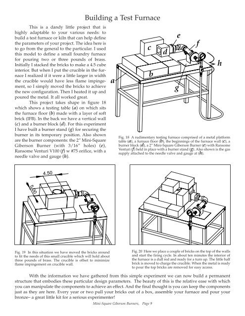
This project takes shape in figure 18<br />
which shows a testing table (a) on which sits<br />
the furnace floor (b) made with a layer of soft<br />
brick (IFB). In the back we have a vertical wall<br />
(c) and a burner block (d). For this experiment<br />
I have built a burner stand (g) for securing the<br />
burner in its temporary position. Also shown<br />
are the burner components: the 2” Mini-Square<br />
Giberson Burner (with 3/16” holes) (e),<br />
Ransome Venturi V100 (f) w #75 orifice, with a<br />
needle valve and gauge (h).<br />
5.00<br />
4.50<br />
Fig. 19 In this situation we have moved the bricks around<br />
to fit the needs of this small crucible which will hold about<br />
three pounds of brass. The crucible is offset to <strong>mini</strong>mize<br />
flame impingement on crucible wall.<br />
Building a Test Furnace<br />
a<br />
c<br />
b<br />
Mini-Square Giberson Burners, <strong>Page</strong> 9<br />
d<br />
Fig. 18 A rudimentary testing furnace comprised of a metal platform<br />
table (a), a furnace floor (b), the beginnings of the furnace wall (c), a<br />
burner block (d), a 2” Mini-Square Giberson Burner (e) with Ransome<br />
Venturi (f) held in place with a burner stand (g). Also shown is the gas<br />
supply attached to the needle valve and gauge at (h).<br />
e<br />
g<br />
Fig. 20 Here we place a couple of bricks on the top of the walls<br />
and start the firing cycle. In about ten minutes the interior of<br />
the furnace is a dull red and ready for a turn up. The little half<br />
brick is moved to charge the crucible. When the metal is ready<br />
to pour the top bricks are removed for easy access.<br />
With the information we have gathered from this simple experiment we can now build a permanent<br />
structure that embodies these particular design parameters. The beauty of this is the relative ease with which<br />
you can manipulate the components to achieve an effect. And the final thought is you can keep the components<br />
just as they are here. Every year or two pull your bricks out of a box, assemble your furnace and pour your<br />
bronze– a great little kit for a serious experimenter!<br />
f<br />
h