

Michel Waleczek
Michel Waleczek
Michel Waleczek

You also want an ePaper? Increase the reach of your titles
YUMPU automatically turns print PDFs into web optimized ePapers that Google loves.
C1<br />
C2<br />
C3<br />
S1<br />
D1<br />
IC1<br />
+ -<br />
JP1<br />
R14<br />
R2<br />
R4<br />
030451-1<br />
C6 C7 C8<br />
C9<br />
R3<br />
R1<br />
IC3 IC4 IC5<br />
IC2<br />
C4<br />
R13<br />
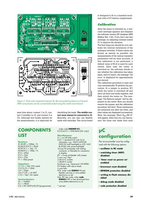
Figure 5. Track and component layouts for the associated printed circuit board.<br />
SMD components can be conveniently tested using the small circuit board.<br />
seen from above: contact 1 to J1, contact<br />
2 (middle) to J2, and contact 3 to<br />
J3). Although this hardly matters for<br />
the measurements, it is important for<br />
J1<br />
J2<br />
R6<br />
R15<br />
1615<br />
1<br />
R8<br />
COMPONENTS<br />
LIST<br />
Resistors:<br />
R1,R5,R9 = 100kΩ, 1%<br />
R2,R6,R10,R13 = 5kΩ6<br />
R3,R7,R11 = 1kΩ, 1%<br />
R4,R8,R12 = 100Ω, 1%<br />
R14 = 47kΩ<br />
R15 = 33Ω<br />
R16 = 27Ω<br />
P1 = 10kΩ preset<br />
Capacitors:<br />
C1,C3 = 10µF 25V radial<br />
C2,C5,C9 = 100nF<br />
C4 = 100pF<br />
C6,C7,C8 = 1nF MKT<br />
C10 = 10µF 16V radial<br />
C5<br />
Semiconductors:<br />
D1 = 1N4001<br />
IC1 = 78L05<br />
IC2 = PIC16F876-20/SP (programmed,<br />
R7<br />
R5<br />
R10<br />
R12<br />
J3<br />
R11<br />
R9<br />
14<br />
(C) ELEKTOR<br />
030451-1<br />
LCD1<br />
P1<br />
identifying the leads. The middle contact<br />
must always be connected to J2.<br />
Naturally, you can also use flexible<br />
leads with miniclips. The circuit board<br />
is designed to fit in a standard enclosure<br />
with a 9-V battery compartment.<br />
Calibration<br />
After the tester is switched on, a welcome<br />
message appears and displays<br />
the software version (SC-Analyser 2005<br />
Elektor Rev. 1.0e). If you don’t see this<br />
message, try adjusting contrast control<br />
P1 to improve the situation.<br />
The first thing you should do is to calibrate<br />
the internal resistances of the<br />
analogue switches. If these values are<br />
known as exactly as possible, the<br />
measurements of the various transistor<br />
parameters will be more accurate. If<br />
this calibration is not performed, a<br />
default value of 65 Ω is used for each<br />
switch. Each time the tester is<br />
switched on, the software checks to<br />
see whether the calibration has taken<br />
place, and if it hasn’t, the message ‘Cal<br />
error’ is displayed for approximately<br />
one second.<br />
The calibration procedure is easy and<br />
runs automatically. To perform the procedure,<br />
fit a jumper in position JP1<br />
while the tester is switched off and<br />
short all three test leads together, and<br />
then switch the tester on. The message<br />
‘Cal Remove jumper’ will be displayed<br />
on the tester. Now you should<br />
remove the jumper, and the calibration<br />
procedure will start. Three resistances<br />
are measured one after the other, and<br />
their values are displayed successively.<br />
Next, the message ‘Short R SH XX Ω’’<br />
will appear. After this you can disconnect<br />
the three test leads from each<br />
4/2005 - elektor electronics 39<br />
3<br />
1<br />
2<br />
2<br />
1<br />
3<br />
ELEKTOR<br />
(C)<br />
030451-1<br />
K1<br />
ELEKTOR<br />
order code 040409-41)<br />
IC3,IC4,IC5 = 74HC4052 (HC only!)<br />
Miscellaneous:<br />
S1 = on/off slide switch<br />
LCD1 = standard LCD with 2x16<br />
characters, e.g., ASI-G-162FS-GF-<br />
EWS/W (with backlight) or LCD 162C<br />
BL (P-LED with active backlight)<br />
16-way SIL pinheader with mating<br />
connector, or flatcable for connection<br />
to display<br />
JP1 = 2-way pinheader with jumper<br />
3 mini croc clips*<br />
3 DIL16 IC sockets<br />
1 DIL28 IC socket<br />
Enclosure, e.g., Hammond 1591BTBU<br />
9-V battery with clip-on leads<br />
5wire links<br />
PCB, order code 030451-1 (see<br />
Readers services or www.elektorelectronics.co.uk)<br />
Disk, PIC hex code, order code<br />
030451-11 or free download from<br />
www.elektor-electronics.co.uk<br />
* see text<br />
1<br />
1<br />
2<br />
3<br />
3<br />
2<br />
ELEKTOR<br />
µC<br />
configuration<br />
The microcontroller must be configured<br />
with the following options:<br />
– oscillator in RC mode<br />
– watchdog timer (WDT)<br />
disabled<br />
– ‘timer reset on power on’<br />
enabled<br />
–brownout reset disabled<br />
– EEPROM protection disabled<br />
– writing to Flash memory disabled<br />
– debug mode disabled<br />
– code protection disabled