Model 380 A&E Specifications - Southwest Microwave, Inc.
Model 380 A&E Specifications - Southwest Microwave, Inc.
Model 380 A&E Specifications - Southwest Microwave, Inc.

You also want an ePaper? Increase the reach of your titles
YUMPU automatically turns print PDFs into web optimized ePapers that Google loves.
<strong>Southwest</strong> <strong>Microwave</strong>, <strong>Inc</strong>.<br />
9055 S. McKemy Street<br />
Tempe, Arizona 85284 USA<br />
(480) 783-0201 - Fax (480) 783-0401<br />
Product <strong>Specifications</strong><br />
1.0 DESCRIPTION<br />
MODEL <strong>380</strong> K-BAND OUTDOOR MICROWAVE TRANSCEIVER<br />
SPECIFICATION<br />
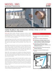
<strong>Model</strong> <strong>380</strong> is a monostatic K-band <strong>Microwave</strong> Intrusion Sensor for indoor and outdoor applications.<br />
A Range Cut-off (RCO) circuit attenuates targets beyond the selected coverage area. The RCO<br />
distance is selected by means of an internal potentiometer. A Zero Range Suppression (ZRS) circuit<br />
reduces the effects of rain on the radome. The unit is equipped with synchronization and addressing<br />
circuitry that enables multiplexing of up to 16 units without mutual interference.<br />
2.0 APPLICABLE DOCUMENTS<br />
F.C.C. Rules & Regulations, Part 15.<br />
3.0 SYSTEM PERFORMANCE<br />
3.1 Target Characteristics<br />
3.1.1 Minimum Cross Section<br />
0.8 square meter (man/woman walking)<br />
0.07 square meter (man/woman crawling)<br />
77 pound (35kg) human - walking, running, hands and knees crawling, or jumping.<br />
Prone crawling or rolling 77 pound human (35kg) or simulated with a 12 inch<br />
(30cm) diameter metal sphere, detected at maximum range of 150 feet (45.8m)<br />
with special site preparation.<br />
3.1.2 Target Velocity<br />
3.2 Coverage Pattern<br />
0.2 ft/sec to 26 ft/sec (0.06m/sec to 7.9m/sec)<br />
3.2.1 For upright walking or running man/woman, teardrop shaped detection pattern 200<br />
feet (60.9m) long, 24 feet (7.3m) wide at widest point (maximum sensitivity), both<br />
azimuth and elevation.<br />
3.2.2 For prone crawling (commando-style) man/woman, 150 feet (45.8m) long, 15 feet<br />
(4.6m) wide.<br />
3.3 Range Cut-Off<br />
3.3.1 shall have an adjustable range cut-off providing continuous adjustment from 50 feet<br />
(15.2m) to 200 feet (60.9m) on man/woman walking. Tolerance on RCO distance<br />
shall be ± 10%. Signals from objects beyond the range cut-off distance shall be<br />
attenuated by at least 40 dB.
3.4 Sensitivity<br />
3.4.1 Threshold to Noise Ratio<br />
13.8dB minimum (prior to integration).<br />
3.4.2 False Alarm Rate<br />
One per year based on S/N (signal to noise) ratio.<br />
3.4.3 Sensitivity control shall have 18dB adjustment range.<br />
3.5 Transmitter Characteristics<br />
3.5.1 Type<br />
The transmitter shall be a cavity stabilized fundamental Gunn oscillator.<br />
3.5.2 Transmitter Output Power<br />
32 milliwatts (15dBm) peak<br />
3.5.3 Modulation<br />
Shall be modulated by 3.12% duty cycle. Pulsed at 32.0 kHz ± 10%.<br />
3.5.4 Unmodulated Carrier Frequency (Fo) and A and B Frequency<br />
24.125 ± .025 GHz (Fo). (Frequency A is Fo-15MHz. Frequency B is Fo+15MHz.)<br />
3.5.5 Frequency Modulation<br />
On alternate pulses the frequency shall shift by 0.6 MHz ± 10%.<br />
3.5.6 Spurious Emissions<br />
All spurious signals including harmonics shall be at least 50dB below the unmodulated<br />
carrier when measured 100 feet from the transmitter.<br />
3.5.7 Polarization<br />
Shall be circular with axial ratio of less than 2dB.<br />
3.5.8 Antenna<br />
3.6 Power Requirements<br />
3.6.1 Voltage<br />
3.6.2 Current<br />
3.6.3 Fusing<br />
Beam width: 8 degrees. Gain: 22.4dB.<br />
11.0 to 14.0 VDC.<br />
160 mA normal, 220 mA synchronized<br />
<strong>380</strong>SPEC_B.DOC
3.7 Remote Monitor<br />
The input power line shall be fused with a .25 amp fuse.<br />
Shall utilize baseplate mounted MS3102A-14S-6S connector for remote test. To be used in<br />
conjunction with RM82 or RM83 performance monitor and mating connector MS3106A-<br />
14S-6P. The pin connections shall be as follows:<br />
PIN VOLTAGE<br />
A Input power 11-14 VDC<br />
B Internal supply (8.5 VDC ± 10%)<br />
C Alignment (2.5 VDC typical)<br />
D Ground<br />
E Doppler sensitivity<br />
F Alarm Status: +12 VDC "IN"<br />
0 VDC "OUT"<br />
3.8 Alarm Indication<br />
By relay contacts, one normally open, one normally closed, and one common. Contact<br />
rating 2 amps at 28 VDC. (Form C) The alarm shall be activated for two seconds (± .25<br />
seconds).<br />
3.9 Display<br />
Three LED displays shall be provided; one indicating a power "ON" condition (red), one<br />
indicating an alarm condition (red), and one indicating a "synchronized lock" condition (red).<br />
NOTE: In synchronized mode, master LED is always illuminated, slave LED’s are off<br />
indicating "locked" condition.<br />
3.10 Tamper Protection<br />
Shall have switch actuated by radome cover. Switch shall have one normally open, one<br />
normally closed and one common terminal. Contact rating 2 amps at 28 VDC.<br />
Blockage detector shall generate alarm if metal enclosure is placed over radome.<br />
3.11 Gain Adjustment<br />
Independent adjustments shall be provided inside the radome for detection pattern length<br />
(RCO) and width (sensitivity).<br />
3.12 Remote Test<br />
A terminal shall be provided which, when activated by a momentary 5 to 15 VDC signal will<br />
test the sensor to simulate an intrusion signal and provide an alarm indication. The circuit<br />
shall be protected such that the application of +15 volts for an indefinite period of time shall<br />
not cause damage.<br />
3.13 Synchronization<br />
4.0 MECHANICAL<br />
Five terminals shall be provided for multiplexing units together to eliminate mutual interference.<br />
An address switch shall be provided to set time slot for synchronization code. The<br />
external clock shall be 1 kHz ± 5% square wave. An enable/disable (on/off)<br />
synchronization switch shall be provided.<br />
<strong>380</strong>SPEC_B.DOC
4.1 Baseplate<br />
10.6 inches diameter (27cm) primer washed per MIL-P-15328 and painted No. 10080<br />
brown per FED STD 595A, exterior catalyst V66V29.<br />
4.2 Radome<br />
Tan ABS UV resistant with rain shield VSWR less than 1.25:1 at 24.125 GHz.<br />
4.3 Shielding<br />
All sensitive sensor circuitry shall be enclosed in an integral metallic enclosure and all input<br />
and output lines shall be filtered.<br />
4.4 RF Filter<br />
4.5 Conduit<br />
Shall incorporate a high pass filter with cutoff at 20 GHz.<br />
The unit shall be equipped with a ½ inch right angle liquid tight flexible conduit fitting for<br />
power and alarm signal wires.<br />
4.6 Mounting.<br />
Shall be supplied with ball swivel and U-bolt assembly for mounting to four inch O.D. post or<br />
flat surface (wall).<br />
4.7 Terminal Strip<br />
5.0 ENVIRONMENTAL<br />
Terminal strip shall provide following connections:<br />
a) +12 VDC i) Remote Test<br />
b) Ground j) Master - HI<br />
c) Tamper N.O. k) Master - LO<br />
d) Tamper Common l) Shield Ground<br />
e) Tamper N.C. m) Slave - HI<br />
f) Alarm N.O. n) Slave - LO<br />
g) Alarm Common<br />
h) Alarm N.C.<br />
5.1 Operating Temperature Range<br />
Shall be -30°F to +150°F (-35°C to +66°C).<br />
5.2 Relative Humidity<br />
Shall operate over 0 to 100% relative humidity.<br />
5.3 Radio Frequency Interference<br />
5.3.1 Radiated Emissions<br />
The unit shall not alarm when subjected to radiated emissions of 10 volt/meter from<br />
10 MHz to 1 GHz.<br />
5.3.2 Transient Protection<br />
<strong>380</strong>SPEC_B.DOC
A 1.5 KE18 transorb shall be incorporated on the input power line for transient<br />
protection.<br />
<strong>380</strong>SPEC_B.DOC