POSIDYN® SDS 5000 TOP PERFORMANCE - Werbeagentur Straub
POSIDYN® SDS 5000 TOP PERFORMANCE - Werbeagentur Straub
POSIDYN® SDS 5000 TOP PERFORMANCE - Werbeagentur Straub

You also want an ePaper? Increase the reach of your titles
YUMPU automatically turns print PDFs into web optimized ePapers that Google loves.
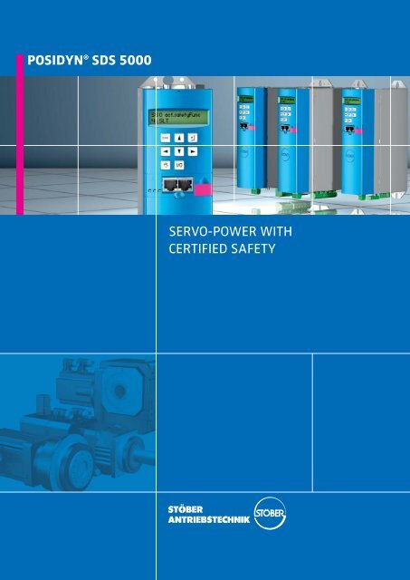
POSIDYN ® <strong>SDS</strong> <strong>5000</strong><br />
SERVO-POWER WITH<br />
CERTIFIED SAFETY
POSIDYN ® <strong>SDS</strong> <strong>5000</strong> <strong>TOP</strong> <strong>PERFORMANCE</strong> – AND<br />
Servo inverters with functional safety offer huge potential for rationalisation<br />
Motion Control<br />
The POSIDYN ® <strong>SDS</strong> <strong>5000</strong> servo<br />
inverter offers maximum torque,<br />
speed and position control performance.<br />
It is designed for challeng -<br />
ing servo technology tasks, based<br />
on the latest technology.<br />
As a member of STÖBER’s 5 th inverter<br />
generation, this powerful and<br />
innovative servo inverter can utilise<br />
all the potential of the new STÖBER<br />
software suite V5.4.<br />
The sophisticated hardware includes<br />
the integrated safety technology<br />
with the six safety functions which<br />
are important for everyday operations<br />
and a comprehensive brake<br />
management system. So the POSI-<br />
DYN ® <strong>SDS</strong> <strong>5000</strong> operates safely as<br />
well as reliably.<br />
With a new secure remote service<br />
concept, STÖBER ANTRIEBSTECHNIK<br />
puts the spotlight on a sensitive<br />
subject previously given little consideration.
INTEGRATED SAFETY SYSTEM<br />
New Machinery Directive<br />
and new safety technology<br />
The new EU Machinery Directive<br />
stipulates tighter safety requirements<br />
for hardware, machinery<br />
and equipment which need safety<br />
precautions when in operation.<br />
The period of adaptation ends on<br />
29 December 2009.<br />
Safety technology is an important<br />
theme for manufacturers and op -<br />
er ators. The consequence of this<br />
development is a requirement for<br />
clearly structured, cost-effective<br />
safety solutions.<br />
Safety functions are required when<br />
machine operators or service personnel<br />
have to carry out work in a<br />
hazard area.<br />
There is a need for servo inverters<br />
with functional safety features for<br />
servo axes in these critical areas.<br />
They give fail-safe execution of all<br />
the actions without additional electromechanical<br />
devices.<br />
The POSIDYN ® <strong>SDS</strong> <strong>5000</strong> servo inverter<br />
is equipped with six safety<br />
functions and is well prepared for<br />
the requirements of the new Machinery<br />
Directive.<br />
Functional safety conforming<br />
with SIL 2<br />
The integrated, encoderless safety<br />
functions enable the POSIDYN ®<br />
<strong>SDS</strong> <strong>5000</strong> servo inverter to be used<br />
in all safety-relevant applications<br />
in SIL 2 (Safety Integrity Level).<br />
On activation, the STO and SS1 safe -<br />
ty functions provide safe isolation<br />
of the energy supply to the motor<br />
(stop function).<br />
The SS2, SOS, SLS and SLT safety<br />
functions provide reliable monitor -<br />
ing of the drive in operation or in<br />
transient exceptional circumstances<br />
such as set-up or maintenance<br />
work. The control function remains<br />
active; so the drive axis can contin -<br />
ue to operate when the job is complete.<br />
The safety functions can also oper -<br />
ate without the use of a safety-ori -<br />
ented feedback system.<br />
STO Safe Torque Off SS2 Safe Stop 2 (IEC 60204-1 Kat. 2) SLS Safely Limited Speed<br />
SS1 Safe Stop 1<br />
SOS Safe Operating Stop SLT Safely Limited Torque
INTEGRATED BUS<br />
Integrated bus for performance, convenience and safety<br />
The self-configuring integrated bus<br />
(IGB) is a standard feature on the<br />
new POSIDYN ® <strong>SDS</strong> <strong>5000</strong> servo inverter.<br />
This technology enables a wide variety<br />
of communication and func -<br />
tional concepts between a number<br />
of servo inverters and interfaces to<br />
be real-time controlled.<br />
Every POSIDYN ® <strong>SDS</strong> <strong>5000</strong> in the<br />
IGB network transmits cyclic data<br />
on the IGB motion bus and can itself<br />
access the data in the network.<br />
A field bus (e.g. PROFIBUS, CAN,<br />
EtherCAT) is ideally used for communication<br />
with a higher-level<br />
control system.<br />
Two RJ45 connectors (X3) are locat -<br />
ed on the front of the housing for<br />
different potential uses of the IGB:<br />
� IGB motion bus:<br />
Communication between servo<br />
inverters<br />
� Direct access from PC to servo<br />
inverter<br />
� Internet access for remote<br />
service<br />
User friendly with the IGB<br />
motion bus<br />
The IGB motion bus function is activated<br />
via the POSITool device and<br />
parameterization software configuration<br />
assistant.<br />
Leading axis positions for synchronous<br />
running or electronic cam<br />
applications (for example) can be<br />
exchanged through the IGB motion<br />
bus.<br />
Every POSIDYN ® <strong>SDS</strong> <strong>5000</strong> servo<br />
inverter can transmit and read up<br />
to six different parameters (max.<br />
of 26 bytes of data) on the IGB<br />
motion bus. These parameters can<br />
come from different <strong>SDS</strong> <strong>5000</strong><br />
series models.
IGB NETWORK<br />
IGB network<br />
To configure an IGB network with<br />
several servo inverters in the POSI-<br />
DYN ® <strong>SDS</strong> <strong>5000</strong> series requires only<br />
a cable connection on the front of<br />
the housing. When the inverters<br />
are switched on, the network configuration<br />
is automatic.<br />
Additional inverters in the series<br />
can be integrated in the IGB network<br />
by hook-up.<br />
Up to 32 axes can be operated in<br />
the IGB network. Every servo inverter<br />
in the network can be accessed<br />
for the diagnosis of the IGB network.
SAFE BRAKE ACTIVATION<br />
Integrated actuation of motor brake and ServoStop<br />
motor adapter<br />
The safety functions of the POSI-<br />
DYN ® <strong>SDS</strong> <strong>5000</strong> servo inverter are<br />
supplemented by a brake control<br />
system for SIL 2 (SBC: safe brake<br />
control) safety-relevant ap plications.<br />
The brake technology of the SMS<br />
geared motors is fully integrated in<br />
the braking management of software<br />
suite V5.4.<br />
The brake mana ge ment offers the<br />
following innovative functions for<br />
both brake sys tems<br />
� Cyclic brake test<br />
� Brake run-in<br />
Compliance with the individually<br />
preset parameters is tracked on the<br />
software side. If the brake test is<br />
omitted, the relevant axis shuts<br />
down.<br />
The motor brake is controlled by the<br />
open load, short circuit and overheating<br />
protective functions. The<br />
ServoStop motor adapter monitors<br />
brake wear with sensor technology.<br />
SMS geared motor with redundant brakes<br />
Optional:<br />
brake module BRM5001<br />
With the optional brake module<br />
BRM5001, the POSIDYN ® <strong>SDS</strong> <strong>5000</strong><br />
servo inverter can control one or<br />
two 24 V brake systems.<br />
SMS geared motor with<br />
ServoStop and motor brake<br />
SMS geared motors can also be<br />
equipped with ServoStop motor<br />
adapter.<br />
The ServoStop motor adapter is<br />
a fail-safe spring-operated brake.<br />
It operates automatically in a<br />
power failure or emergency stop.<br />
The ServoStop motor adapter is<br />
compatible with all SMS geared<br />
motors.
SECURE REMOTE SERVICE<br />
Preliminary remarks:<br />
Remote service is increasing ly in<br />
demand and in use due to its tremendous<br />
cost saving potential.<br />
But it is clear that its safety aspects<br />
are rarely considered. Lack of organisational<br />
and legal clarity can result<br />
in unintended or unauthorised<br />
changes having to be accepted in<br />
an emergency with all the consequences.<br />
>> Defining and safeguarding res -<br />
ponsibility is therefore a fundamental<br />
component of the STÖBER<br />
remote service concept.<br />
STÖBER remote service<br />
concept<br />
The STÖBER remote service concept<br />
requires the participants to adopt a<br />
regulated approach. The remote service<br />
professional can be sure that<br />
he is communicat ing with a responsible<br />
person on the spot who is in<br />
charge of.<br />
All the operations and processes<br />
forming part of local servicing can<br />
be carried out via the STÖBER remote<br />
service.<br />
Remote service includes any indirect<br />
link between a PC (with POSITool<br />
device and parameterization software)<br />
and a POSIDYN ® <strong>SDS</strong> <strong>5000</strong><br />
servo inverter or IGB network.<br />
The link can be made through the<br />
Internet or a local network.<br />
System integrated control of responsibility<br />
A responsible employee of the operator<br />
or machine manufacturer<br />
activates the remote service request<br />
locally as required. This is done directly<br />
via the POSIDYN ® <strong>SDS</strong> <strong>5000</strong><br />
servo inverter or the PLC.<br />
He also contacts the service technician<br />
concerned.<br />
This ensures that the responsible<br />
person is present locally at the machine<br />
to check the facts and personnel<br />
safety.<br />
IGB network<br />
Company network Remote<br />
maintenance<br />
If the remote service request goes<br />
via the Internet, an outgoing connection<br />
is made, so that the sys tem<br />
administrators do not have to isolate<br />
specific ports. A safety gap is<br />
not left in the operator’s system.<br />
The service technician logs onto the<br />
relevant servo inverter with POSI-<br />
Tool via this Internet access.
SOFTWARE SUITE V5.4<br />
The software suite V5.4 consists of<br />
the POSITool device and parameterization<br />
software, an extensive<br />
library of standard applications and<br />
the firmware for the <strong>5000</strong> inverter<br />
generation.<br />
POSITool offers the following<br />
functions:<br />
� Application configuration<br />
� Drive parameterization<br />
� Drive programming<br />
� Drive commissioning<br />
� Application commissioning<br />
� Function optimization<br />
brake management<br />
� Parameterization of safety<br />
function<br />
� Diagnostics<br />
Parameter<br />
Configuration<br />
P01<br />
P02<br />
Firmware<br />
P03<br />
With the development of POSITool,<br />
a fully integrated 3-layer architecture<br />
has been created. It is convinc -<br />
ing due to its clarity, optimum oper-<br />
ational safety, program generation<br />
efficiency and accurate commission -<br />
ing. All the parameteri zation work<br />
is supported by assistant functions.<br />
Quick, easy and accurate with the parameterization assistant<br />
Application library and<br />
parameterization assistant<br />
The application library with tailormade,<br />
project-related basic applica<br />
tions offers modules for:<br />
� Fast reference value<br />
� Technology controller<br />
� Comfort reference value<br />
Speed or torque reference<br />
value (selectable)<br />
3 analog reference values<br />
16 fixed reference values<br />
Motorized potentiometer<br />
PID controller reference value<br />
Reference values scalable as<br />
absolute or percentage value<br />
� Motion block positioning<br />
� Command positioning with<br />
the special POSILatch function.<br />
Position measurements can then<br />
be taken on external signals<br />
(e.g. linear measurements).<br />
� Synchronous command<br />
positioning<br />
� Electronic cam<br />
For general users<br />
Users are given active support with<br />
programming of standard applications<br />
because the modules are always<br />
project-oriented. The assis tant<br />
function ensures that parameterization<br />
proceeds efficiently.<br />
For experts<br />
Trained and experienced users can<br />
use the graphics editor layer (with<br />
Motion Control in acc. w. PLCopen)<br />
for configuration of customer applications.
PROFESSIONAL IN THE BEST SENSE<br />
Tailor made application<br />
With this service STÖBER ANTRIEBS-<br />
TECHNIK provides the facility to<br />
have individual functional upgrades<br />
or full adaptations to basic applications<br />
specifically programmed.<br />
These programs have application<br />
protection.<br />
Other highlights<br />
The software scalability allows op-<br />
timum adaptation of functionality<br />
and response time to the application.<br />
The cycle time for reference<br />
value processing depends only on<br />
the calculation of the activated sys -<br />
tem modules and the parameters.<br />
Even complex applications can be<br />
mapped on the same hardware<br />
platform without modifying the<br />
firmware.<br />
The STÖBER POSISwitch ® AX 5001<br />
axis changeover switch is prepared<br />
for use by the software. Up to 4<br />
servo axes with different function -<br />
a lities can be controlled alternately.<br />
User-friendly system maintenance<br />
The documentation feature of the<br />
POSITool user software facilitates<br />
thorough system maintenance. The<br />
fine-tuned settings and operational<br />
data of each drive are recorded and<br />
documented.<br />
The data of each individual drive<br />
are thus available for system maintenance<br />
or further configurations.<br />
With the diagnostic function, the<br />
cause of a fault can be found quick -<br />
ly with a notebook. The analysis of<br />
the ‘error data’ by POSITool helps<br />
service engineers to locate the actual<br />
cause quickly. If a drive fails due<br />
to overload or damage, the cause<br />
can be an undetected problem area<br />
elsewhere.
MULTIPLE USE BY AXIS CHANGEOVER SWITCH<br />
When technical safety functions<br />
are used, POSISwitch ® cannot be<br />
used.<br />
Multiple use by alternate<br />
control of different servo<br />
drives<br />
Servo drives often go into action at<br />
timed intervals. Typical examples<br />
of this are handling operations and<br />
format adjustments. Multimotor<br />
operation with only one POSIDYN ®<br />
<strong>SDS</strong> <strong>5000</strong> servo inverter is suitable<br />
for these applications.<br />
Alternate<br />
conrol of several<br />
servo drives<br />
Axis changeover switch<br />
The POSISwitch ® AX 5001 external<br />
module has been developed for con -<br />
nection of the digitally con troll ed<br />
servo motors. Actuation is just via<br />
the existing encoder cables, with -<br />
out further operations.<br />
Software<br />
The POSITool software can manage<br />
up to four separate position or<br />
speed regulated axes and control<br />
them alternately. A smooth transition<br />
from axis to axis is guaranteed<br />
by the software.<br />
Power and signal flows are controlled<br />
with correct timing. The axis<br />
management does not require additional<br />
software complexity in a<br />
primary control.<br />
POSISwitch ® AX 5001<br />
Sequential operation with -<br />
out functional limitation<br />
If four drives are used as endless<br />
axes with absolute encoders, the<br />
exact positioning is still free from<br />
rounding errors even if the geared<br />
motors have different, also non<br />
whole number, gear ratios.
ACCURATE COMMISSIONING<br />
Commissioning the STÖBER<br />
ED and EK servo motors<br />
The system is commissioned with<br />
the help of a notebook and the POSI-<br />
Tool device and parameterization<br />
software. No software knowledge<br />
is required for this. All the adjustments<br />
are done interactively. The<br />
POSIDYN ® <strong>SDS</strong> <strong>5000</strong> inverter comes<br />
supplied with the ‘fast reference<br />
value’ application.<br />
STÖBER EK servo motor<br />
with digital EnDat ® 2.2 absolute encoder<br />
on the motor shaft (B-side)<br />
Commissioning<br />
the complete application<br />
This can be done either via the connected<br />
PC or after data transfer via<br />
the device operator panel.<br />
The Paramodul is also suitable for<br />
data transfer.<br />
Further parameterization corrections<br />
and additions can be made<br />
directly. Some knowledge (basic<br />
training) is necessary for this task.<br />
Digital drive tuning<br />
The POSIScope software tool reduces<br />
trial runs for individual drive<br />
optimization to a minimum.<br />
Trial and error is replaced by a full<br />
diagnosis. In real time the pro cedure<br />
is observed, recorded, analyzed and<br />
immediately displayed by oscillograph<br />
on the PC monitor. The fine<br />
tuning thus obtained results in perfectly<br />
adjusted STÖBER drives.<br />
On applications with high specifications,<br />
POSIScope can be used for<br />
sys tem maintenance.<br />
Device replacement with -<br />
out expert knowledge<br />
All the application parameters of a<br />
drive are stored in the Paramodul<br />
memory module in parallel with the<br />
device memory.<br />
If a POSIDYN ® <strong>SDS</strong> <strong>5000</strong> has to be<br />
replaced, the existing Para modul is<br />
simply plugged in again to restart<br />
operations. The functionality is retained<br />
without restriction.
THE COMPLETE HARDWARE<br />
The optimized system technology.<br />
POSIDYN ® <strong>SDS</strong> <strong>5000</strong> and SMS geared motors<br />
The SMS product range comprises<br />
ServoFit ® planetary gear units and<br />
SMS precision gear units which are<br />
directly mounted on the STÖBER ED<br />
and EK servo motors to form the<br />
SMS geared motors.<br />
For higher safety requirements for<br />
SMS geared motors, the ServoStop<br />
motor adapter brake can be used<br />
as a redundant braking system.<br />
�<br />
The new SMS KS right-angle servo<br />
geared motor � has created a further<br />
series designed as a compact<br />
complete drive. The SMS rightangle<br />
servo geared motor stands<br />
for extremely high demands on dynamics<br />
or continuous duty endurance<br />
at a high speed level.<br />
Digital encoder interface<br />
� New EnDat ® format 2.2<br />
� 4 MHz data rate<br />
� Up to 100 m cable length<br />
Display and keypad are integrated.<br />
So rapid diagnosis, status monitor -<br />
ing, direct parameter access and<br />
jogging (manual operation func -<br />
tions) are possible.
PRACTICAL IN EVERY WAY<br />
Functional modular<br />
housing design<br />
The operator module is the same<br />
for all the sizes.<br />
The sheet steel housing design is<br />
part of the STÖBER EMC strategy.<br />
It shields against electromagnetic<br />
interference.<br />
This increases the units' RFI im munity<br />
and reduces interference emission.<br />
The front is the only part made<br />
of plastic which is pleasant to the<br />
touch.<br />
Connection layout<br />
The connections for motor, DC link<br />
and braking resistor are located on<br />
the bottom of the housing.<br />
<strong>SDS</strong> 5007/5008/5015<br />
Size 0<br />
The mains or 24 V supply connection<br />
is made ‘from above’ through<br />
a plug-in terminal strip.<br />
<strong>SDS</strong> 5040/5075<br />
Size 1<br />
175 70<br />
260<br />
70<br />
283<br />
300<br />
283<br />
300<br />
Installation<br />
The POSIDYN ® <strong>SDS</strong> <strong>5000</strong> servo inverters<br />
are suitable for installation in<br />
compact control cabinets 300 mm<br />
deep.<br />
<strong>SDS</strong> 5110/5150<br />
Size 2<br />
105<br />
283<br />
300<br />
<strong>SDS</strong> 5220/5370/5450<br />
Size 3<br />
276<br />
190<br />
365<br />
383
SAFE INDUSTRIAL ELECTRONICS<br />
Powerful processor core<br />
32-bit RISC processor<br />
Current controller 62.5 μs<br />
Position and speed controller 250 μs<br />
Communication processor<br />
For all IGB motion functionalities<br />
Control modes<br />
Synchronous servo motors<br />
Asynchronous motors<br />
(V/f, sensorless VC, VC)<br />
Encoder interface<br />
Absolute encoder, digital<br />
(EnDat ® 2.2‚ SSI)<br />
Incremental encoder (TTL, HTL)<br />
Optional: Resolver<br />
Option board slots<br />
Communication<br />
I/O Terminals<br />
Fieldbus moduls<br />
CANopen DS-301 (CAN<strong>5000</strong>)<br />
PROFIBUS DP-V1 (DP<strong>5000</strong>)<br />
EtherCAT (ECS<strong>5000</strong>)<br />
I/O Terminal moduls<br />
REA 5001<br />
SEA 5001<br />
XEA 5001<br />
Operational reliability<br />
Generously sized power stage<br />
for 250 % accelerating current<br />
Thermistor motor protection<br />
Monitoring circuit for PTC thermis -<br />
tors<br />
Brake chopper integral<br />
Thermal model monitoring of<br />
external resistor for short circuit<br />
and overload<br />
Size<br />
Type<br />
ID<br />
Recommended motor power<br />
Input voltage<br />
Output frequency<br />
Output voltage<br />
Rated current Irated<br />
I max<br />
Switching frequency<br />
Power loss at Ioutput =Irated<br />
Power loss at Ioutput =0A 1<br />
Overvoltage limit<br />
Brake chopper switching threshold<br />
Brake chopper interrupting voltage<br />
Braking resistor RBr min<br />
Braking resistor PBr min<br />
DC link connection<br />
For energy exchange between<br />
several inverters<br />
Operator unit<br />
8 keys, changing of parameters,<br />
manual operation (clear text<br />
display and LED indicators)<br />
Paramodul<br />
Plug-in module for power failure<br />
safe storage of all application<br />
specific data. Data transfer without<br />
any further aids<br />
Control electronics supply<br />
Power supply unit with connection<br />
facility for external +24 V or DC<br />
link power supply (the control section<br />
remains fully functional even if<br />
the supply voltage is switched off)<br />
<strong>SDS</strong> 5007<br />
49825<br />
(L1–N) 1 x 230 V<br />
+20 %/–40 %, 50/60 Hz<br />
3 x 3 A<br />
80 W<br />
440 V<br />
400 V to 420 V<br />
360 V to 380 V<br />
1.8 kW<br />
1 Depends on the connected option boards and sensors (e.g. encoder)<br />
0.75 kW<br />
Ease of installation<br />
All terminals are plug-in type<br />
(spring-loaded terminals)<br />
Supply and motor connections in<br />
separate places<br />
Twin DC link terminals, facilitates<br />
parallel connection<br />
EMC plate for mounting the shield<br />
of the motor cable<br />
BG 0<br />
<strong>SDS</strong> 5008<br />
49826<br />
0 to 400 Hz<br />
0 to 400 V<br />
3 x 1.5 A<br />
250 % for 2 s; 200 % for 5 s<br />
65 W<br />
max. 30 W<br />
<strong>SDS</strong> 5015<br />
49827<br />
1.5 kW<br />
(L1–L3) 3 x 400 V, +32 %/–50 %, 50 Hz<br />
(L1–L3) 3 x 480 V, +10 %/–58 %, 60 Hz<br />
8 kHz (adjustable to 16 kHz with derating)<br />
100 Ω<br />
830 V<br />
780 V to 800 V<br />
740 V to 760 V<br />
6.4 kW<br />
3 x 3 A<br />
90 W
POSITool Windows Software<br />
Application selection<br />
(with assis tant)<br />
Parameterization<br />
(with assistant)<br />
Manages several servo inverters<br />
in one installation Drive optimization<br />
with POSIScope, oscilloscope<br />
function for internal signals (movement<br />
visualization), operational<br />
data monitoring and diagnosis<br />
Live firmware update<br />
If the firmware is updated, the new<br />
version can be overwritten during<br />
system operation. The update can<br />
be made immediately or automatically<br />
at the next device start.<br />
<strong>SDS</strong> 5040<br />
49829<br />
4.0 kW<br />
3 x 6 A<br />
170 W<br />
100 Ω<br />
6.4 kW<br />
CE compliance<br />
All POSIDYN ® <strong>SDS</strong> <strong>5000</strong> inverters<br />
conform to the applicable EMC<br />
Directives and meet the criteria of<br />
Low Voltage Directive EN 50178.<br />
Standard features comprise an effective<br />
range of measures, among<br />
them an integral EMC filter and the<br />
highquality galvanized sheet steel<br />
inverter housing. Levels and terms<br />
apply as defined by IEC 1131.<br />
All POSIDYN ® servo inverters are<br />
CE-marked.<br />
UL compliant<br />
The inverters are UL and cUL<br />
("Canadian UL") listed and meet<br />
the requirements of UL 508C and<br />
UL 840 standards.<br />
BG 1 BG 2 BG 3<br />
<strong>SDS</strong> 5075<br />
49830<br />
7.5 kW<br />
(L1–L3) 3 x 400 V, +32 %/–50 %, 50 Hz<br />
(L1–L3) 3 x 480 V, +10 %/–58 %, 60 Hz<br />
0 to 400 Hz<br />
0 to 400 V<br />
3 x 10 A<br />
250 % for 2 s; 200 % for 5 s<br />
8 kHz (adjustable to 16 kHz with derating)<br />
max. 30 W<br />
830 V<br />
780 V to 800 V<br />
740 V to 760 V<br />
200 W<br />
47 Ω<br />
13.6 kW<br />
Accessories<br />
POSISwitch ® AX 5001<br />
For sequential control of STÖBER<br />
ED + EK servo motors with digital<br />
absolute encoders<br />
Submounted braking resistors<br />
Braking resistors for installation<br />
at the rear of the unit<br />
Braking resistor<br />
VHPR series<br />
IP 54 enclosure, UL<br />
up to 400 W<br />
<strong>SDS</strong> 5110<br />
49831<br />
11 kW<br />
3 x 14 A<br />
220 W<br />
<strong>SDS</strong> 5150<br />
49832<br />
15 kW<br />
(L1–L3) 3 x 400 V, +32 %/–50 %, 50 Hz<br />
(L1–L3) 3 x 480 V, +10 %/–58 %, 60 Hz<br />
0 to 400 Hz<br />
0 to 400 V<br />
3 x 20 A<br />
250 % for 2 s; 200 % for 5 s<br />
8 kHz (adjustable to 16 kHz with derating)<br />
max. 30 W<br />
830 V<br />
780 V to 800 V<br />
740 V to 760 V<br />
22 Ω<br />
29.1 kW<br />
280 W<br />
<strong>SDS</strong> 5220<br />
49833<br />
22 kW<br />
3 x 30 A<br />
ca. 350 W<br />
<strong>SDS</strong> 5370<br />
49835<br />
37 kW<br />
(L1–L3) 3 x 400 V, +32 %/–50 %, 50 Hz<br />
(L1–L3) 3 x 480 V, +10 %/–58 %, 60 Hz<br />
0 to 400 Hz<br />
0 to 400 V<br />
3 x 50 A<br />
250 % for 2 s; 200 % for 5 s<br />
8 kHz (adjustable to 16 kHz with derating)<br />
ca. 600 W<br />
max. 55 W<br />
830 V<br />
780 V to 800 V<br />
740 V to 760 V<br />
15 Ω<br />
42.7 kW<br />
<strong>SDS</strong> 5450<br />
49836<br />
45 kW<br />
3 x 60 A<br />
ca. 1000 W
www.stoeber.de<br />
Programming<br />
and user training<br />
The POSITool software assistant<br />
supports programming and pa ram<br />
eterization for the use of basic<br />
applications. However, accurate<br />
completion requires appropriate<br />
experience or induction by STÖBER<br />
train ing personnel.<br />
The special STÖBER POSITool programming<br />
course is part of the<br />
“User graphics programming” software<br />
option. The aim of the train -<br />
ing is to learn to make full use of<br />
the universality of the system.<br />
Specific control sequences can then<br />
be implemented by linking the rel evant<br />
modules.<br />
Service<br />
The STÖBER service system comprises<br />
38 expert partners in Germany<br />
and 80 companies in the STÖBER<br />
SERVICE NETWORK worldwide.<br />
This full service concept guarantees<br />
local expertise and availability when<br />
needed.<br />
The service specialists at the Pforzheim<br />
plant are also available on the<br />
help line 24/h.<br />
When necessary, urgent action to<br />
correct a problem can be put in<br />
train immediately.<br />
24/h service hotline<br />
+49(0)180 5 786323<br />
STOBER DRIVES LTD.<br />
Waltham Abbey<br />
ESSEX EN9 1JH<br />
GREAT BRITAIN<br />
eMail: mail@stober.co.uk<br />
www.stober.co.uk<br />
STOBER DRIVES, INC.<br />
MAYSVILLE, KY 41056<br />
USA<br />
eMail: sales@stober.com<br />
www.stober.com<br />
STÖBER ANTRIEBSTECHNIK GmbH<br />
4662 STEYRERMÜHL<br />
AUSTRIA<br />
eMail: office@stoeber.at<br />
www.stoeber.at<br />
STÖBER Schweiz AG<br />
6341 BAAR<br />
SWITZERLAND<br />
eMail: info@stoeber.ch<br />
www.stoeber.ch<br />
STÖBER S.a.r.l.<br />
69300 CALUIRE ET CUIRE<br />
FRANCE<br />
eMail: mail@stober.fr<br />
www.stober.fr<br />
STÖBER TRASMISSIONI s.r.l.<br />
20017 MAZZO DI RHO (MILANO)<br />
ITALY<br />
eMail: info@stoeber.it<br />
www.stoeber.it<br />
STOEBER POLSKA<br />
54516 WROCLAW<br />
POLAND<br />
eMail: biuro@stoeber.pl<br />
www.stoeber.pl<br />
DAE KWANG STOEBER CO. LTD.<br />
SIHEUNG CITY, GYUNGGI DO<br />
REPUBLIC OF KOREA<br />
eMail: dkstoeber@stoeber.co.kr<br />
STÖBER ANTRIEBSTECHNIK GmbH + Co. KG<br />
Kieselbronner Str. 12<br />
75177 PFORZHEIM<br />
GERMANY<br />
Phone +49 (0)7231 582-0<br />
Fax +49 (0)7231 582-1000<br />
eMail: mail@stoeber.de<br />
Subject to technical changes 442112.00K 000 01/08 werbeagentur-straub.de