Cementing the Relationship Between DCS and PLC: A ... - Siemens
Cementing the Relationship Between DCS and PLC: A ... - Siemens
Cementing the Relationship Between DCS and PLC: A ... - Siemens

Create successful ePaper yourself
Turn your PDF publications into a flip-book with our unique Google optimized e-Paper software.
where programming system logic relates to what an operator views on <strong>the</strong> HMI is very useful <strong>and</strong> helps in<br />
underst<strong>and</strong>ing problems <strong>and</strong> speeds up <strong>the</strong> troubleshooting process. The programming environment of a<br />
<strong>PLC</strong>-based on ladder logic is more suitable to <strong>the</strong> programming of <strong>the</strong> inner functions of <strong>the</strong> objects such as<br />
motors or diverters. The internal functions implemented by using ladder logic must be encapsulated in <strong>the</strong><br />
form of function blocks.<br />
Conclusion - Beyond <strong>the</strong> <strong>DCS</strong> vs. <strong>PLC</strong> divides<br />
It is clear that both <strong>PLC</strong> <strong>and</strong> <strong>DCS</strong> were designed to meet two different application requirements. It is also<br />
clear that both kinds of system attributes are required to provide effective control of <strong>the</strong> process systems<br />
<strong>and</strong> automation needed for <strong>the</strong> cement industry.<br />
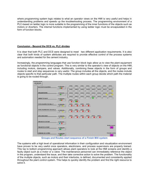
Increasingly, <strong>the</strong> programming languages that use function block logic allow us to view <strong>the</strong> plant equipment<br />
as functional objects in <strong>the</strong> control program. This is very similar to <strong>the</strong> operator’s view of objects on <strong>the</strong> HMI,<br />
including motors, dampers, <strong>and</strong> valves. Additionally, combining <strong>the</strong>se objects in <strong>the</strong> form of groups <strong>and</strong><br />
routes to start <strong>and</strong> stop sequences is very useful. The group includes all <strong>the</strong> objects, <strong>and</strong> <strong>the</strong> routes include<br />
objects specific to that particular path. The multiple routes within each group decide which path <strong>the</strong> material<br />
is going to be routed through.<br />
Groups <strong>and</strong> Routes start sequence of a Finish Mill system<br />
The systems with a high level of operational information in <strong>the</strong>ir configuration <strong>and</strong> visualization environment<br />
have proven to be very useful once operators, electricians, <strong>and</strong> process supervisors are properly trained.<br />
This top to bottom programming approach allows plant operators to look at <strong>the</strong> HMI screens <strong>and</strong> identify a<br />
faulty object such as a motor or a valve. The maintenance personnel can immediately reference <strong>the</strong> object<br />
in <strong>the</strong> program, underst<strong>and</strong> <strong>the</strong> issue, <strong>and</strong> <strong>the</strong>n take corrective action to solve <strong>the</strong> problem. The functionality<br />
of <strong>the</strong> multiple objects, such as motors <strong>and</strong> <strong>the</strong>ir interlocks, is defined, documented <strong>and</strong> consistently applied<br />
throughout <strong>the</strong> plant control system. This helps to quickly identify <strong>the</strong> problem <strong>and</strong> find <strong>the</strong> right resource to<br />
solve it.