Selection of Copper vs. Aluminum Rotors for Induction ... - Siemens
Selection of Copper vs. Aluminum Rotors for Induction ... - Siemens
Selection of Copper vs. Aluminum Rotors for Induction ... - Siemens

Create successful ePaper yourself
Turn your PDF publications into a flip-book with our unique Google optimized e-Paper software.
Copyright © 2000 IEEE. Reprinted from IEEE/PCIC 2000 Conference Record. This material is posted here with permission <strong>of</strong> the IEEE. Such permission <strong>of</strong> the IEEE does not in any<br />
way imply IEEE endorsement <strong>of</strong> any <strong>of</strong> <strong>Siemens</strong>' products or services. Internal or personal use <strong>of</strong> this material is permitted. However, permission to reprint/republish this material <strong>for</strong><br />
advertising or promotional purposes or <strong>for</strong> creating new collective works <strong>for</strong> resale or redistribution must be obtained from the IEEE by sending a blank email message to pubspermissions@ieee.org.<br />
By choosing to view this document, you agree to all provisions <strong>of</strong> the copyright laws protecting it.<br />
<strong>Selection</strong> <strong>of</strong> <strong>Copper</strong> <strong>vs</strong>. <strong>Aluminum</strong> <strong>Rotors</strong> <strong>for</strong> <strong>Induction</strong> Motors<br />
Copyright material IEEE<br />
Paper No. PCIC-2000-19<br />
William R. Finley Mark M. Hodowanec<br />
Senior Member Member<br />
Industrial Products Division Industrial Products Division<br />
<strong>Siemens</strong> Energy & Automation, Inc. <strong>Siemens</strong> Energy & Automation, Inc.<br />
4620 Forest Ave. 4620 Forest Ave.<br />
Norwood, OH 45212 Norwood, OH 45212<br />
Abstract: On squirrel cage induction motors, there is an<br />
important choice between utilizing a lower cost die cast or<br />
fabricated aluminum rotor versus the more expensive copper<br />
bar rotor. Utilizing the wrong rotor construction <strong>for</strong> the<br />
application can either increase costs unnecessarily or lead to<br />
catastrophic failure. This paper will provide the background<br />
necessary to assist in making the proper choice. The<br />
fundamentals <strong>of</strong> rotor construction and basic in<strong>for</strong>mation on<br />
how the induction motor works will be discussed.<br />
Additionally, the effects <strong>of</strong> various materials and types <strong>of</strong><br />
rotor construction on motor per<strong>for</strong>mance will be analyzed.<br />
Index Terms – Motors, <strong>Rotors</strong>, Rotor Construction, <strong>Copper</strong>,<br />
<strong>Aluminum</strong> Die Cast.<br />
I. INTRODUCTION<br />
Many induction motors in service today are running critical<br />
processes in which failure at any time can be very costly.<br />
Many times these critical processes will not have a back up.<br />
As a result a large portion <strong>of</strong> this process will shut down until<br />
the motor is repaired and put back into service. Those aware<br />
<strong>of</strong> this situation will strive to purchase a motor that will<br />
maximize reliability. As a result <strong>of</strong> the strong push <strong>for</strong><br />
maximum reliability, it is easy to over specify costly<br />
components not required <strong>for</strong> the specific application. These<br />
decisions will result in an unnecessarily high motor purchase<br />
price. To maximize reliability without overspending, large<br />
induction motors need to be properly matched to the specific<br />
application. With this consideration the choice between<br />
various rotor constructions needs to be evaluated. It is<br />
generally assumed that copper bar rotors are the most<br />
reliable. In certain applications this may be true, and they<br />
can at times out per<strong>for</strong>m aluminum rotors. But many times,<br />
the applications are such, that there will not be any<br />
appreciable per<strong>for</strong>mance benefit from the use <strong>of</strong> copper bar<br />
rotors. It will be shown later in this paper that the percentage<br />
motor cost increase can be very large on smaller machines<br />
but may not be as significant on larger machines.<br />
With market conditions today, the economics are such that<br />
users and engineers are looking <strong>for</strong> the best fit <strong>for</strong> the<br />
application at the most reasonable cost. As a result they are<br />
looking at purchasing motors utilizing aluminum die cast<br />
rotors in ratings to much greater horsepower than what was<br />
considered practical in the past. Due to advancements in<br />
aluminum die-casting technology, reliable die-cast rotors are<br />
now available in motors up to much larger ratings. Also<br />
available are fabricated aluminum rotors, which have a<br />
Page 1 <strong>of</strong> 11<br />
per<strong>for</strong>mance characteristic closer to the aluminum die cast<br />
rotor, but with a higher cost due to the labor cost associated<br />
with fabrication. All this will be discussed in greater detail<br />
later in the paper.<br />
II. ROTOR CONSTRUCTION<br />
Four types <strong>of</strong> rotor construction exist today: aluminum die<br />
cast (ADC), copper die cast (CuDC), fabricated aluminum<br />
bars (AlBar), and fabricated copper bar (CuBar). In general,<br />
only the aluminum die-cast, fabricated aluminum, and copper<br />
bar rotors are in common use today. At this time this paper<br />
will discuss how these are manufactured.<br />
<strong>Aluminum</strong> Die Cast Construction (ADC):<br />
<strong>Aluminum</strong> die-cast rotors have been manufactured since<br />
the 1930’s. Although this process has been utilized <strong>for</strong> a<br />
long time, the rotor sizes that can be die cast increase each<br />
year due to manufacturing advancements in die cast<br />
technology. Current state <strong>of</strong> the art technology makes it<br />
possible to die cast aluminum rotors with a 30” diameter and<br />
a 50” core length. This is the size rotor that would be<br />
capable <strong>of</strong> producing 10,000 Hp. However, due to tooling<br />
costs and demand it is unusual to see ADC rotors used in<br />
ratings above 1750 HP.<br />
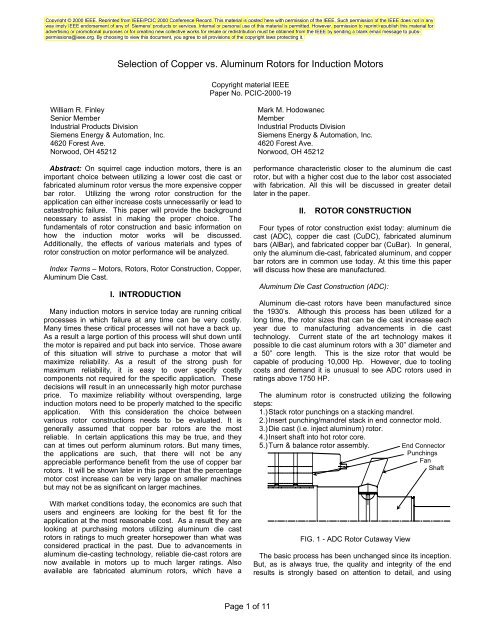
The aluminum rotor is constructed utilizing the following<br />
steps:<br />
1.) Stack rotor punchings on a stacking mandrel.<br />
2.) Insert punching/mandrel stack in end connector mold.<br />
3.) Die cast (i.e. inject aluminum) rotor.<br />
4.) Insert shaft into hot rotor core.<br />
5.) Turn & balance rotor assembly.<br />
FIG. 1 - ADC Rotor Cutaway View<br />
End Connector<br />
Punchings<br />
Fan<br />
Shaft<br />
The basic process has been unchanged since its inception.<br />
But, as is always true, the quality and integrity <strong>of</strong> the end<br />
results is strongly based on attention to detail, and using
state <strong>of</strong> the art technology. In the case <strong>of</strong> die cast rotors, the<br />
following details are important:<br />
• Tight tolerances and close fit <strong>of</strong> the punching ID to<br />
stacking mandrel. This will minimize lamination stagger. The<br />
benefits to minimal stagger are tw<strong>of</strong>old: minimization <strong>of</strong> stray<br />
load loss and thermal sensitivity. Minimizing stray load loss<br />
will result in not only a cooler running motor, but higher<br />
efficiency as well. Minimizing thermal sensitivity (i.e. change<br />
<strong>of</strong> balance as the rotor heats up) will result in having a motor<br />
that maintains low vibration levels cold or hot.<br />
• Rotation <strong>of</strong> rotor punchings while stacking on mandrel.<br />
The sheet steel roll that the rotor laminations are punched<br />
from will have variation in thickness from one side <strong>of</strong> the<br />
sheet to the other. If the punchings are not rotated, then the<br />
thick side will all stack up on one side causing a ‘banana’<br />
shaped rotor. Although the rotor will be machined and trued<br />
up, it will still exhibit more thermal sensitivity than a rotor that<br />
was stacked ‘straight’.<br />
• Consistency <strong>of</strong> die cast clamp and shot pressure. This<br />
will help assure that the die cast aluminum is homogeneous,<br />
and does not ‘leak out’ between the laminations or vent<br />
spacers. If aluminum leaks out anywhere, there will be<br />
increased porosity in the adjacent rotor bars. Additionally, it<br />
should be pointed out that aluminum shrinks 6% on cooling<br />
(i.e. there will be 6% porosity in an aluminum die cast rotor).<br />
If the shot process is not properly controlled (i.e. shot<br />
pressure and shot velocity <strong>vs</strong>. shot ram position), than this<br />
6% will be unevenly distributed. Instead <strong>of</strong> having an even<br />
dispersion <strong>of</strong> fine ‘bubbles’, there will be large, non-evenly<br />
distributed blowholes. This will result in an increase in<br />
resistance in the bar(s) with the blow holes, with a<br />
subsequent increase in the bar temperature relative to the<br />
temperature <strong>of</strong> other bars. This in turn will cause the rotor to<br />
exhibit a high degree <strong>of</strong> thermal sensitivity. Increased clamp<br />
pressure results in an increase in interlaminar core pressure.<br />
The eddy current portion <strong>of</strong> core losses goes up as<br />
interlaminar pressure increases. Additionally, if the clamp<br />
pressure (and thus core pressure) is uneven, thermal<br />
instability can be a problem. Increased core losses can also<br />
occur as a consequence <strong>of</strong> some <strong>of</strong> the aluminum leaking out<br />
between the laminations. In either case, increased porosity<br />
(blow holes) or excessive core pressure will result in hotter,<br />
less efficient motor operation.<br />
• ‘Good Modern Die Cast Practices’ these practices<br />
include cavity vacuum be<strong>for</strong>e the die cast ‘shot’, computer<br />
monitoring <strong>of</strong> ‘shot’, temperature controlled die, etc.<br />
• Shaft should be inserted into a hot core so as to<br />
minimize mechanical stresses associated with the pressing<br />
operation, and allowing the core to shrink onto the shaft<br />
symmetrically. This will help ensure symmetrical thermal<br />
expansion when the motor in operation heats up. The hoop<br />
strength <strong>of</strong> the core as it shrinks on to the shaft should be<br />
sufficient to maintain the shrink fit. The shrink fit on shaft<br />
must be adequate to transmit the torque at maximum speed<br />
and temperature.<br />
Properly designed, manufactured, and applied, aluminum<br />
die cast rotors have the same degree <strong>of</strong> reliability as copper<br />
bar rotors.<br />
Page 2 <strong>of</strong> 11<br />
<strong>Copper</strong> Die Cast Construction (CuDC):<br />
CuDC construction does not differ significantly from ADC<br />
construction. The CuDC imposed manufacturing challenges<br />
that only recently have been met.<br />
In essence the manufacturing details <strong>for</strong> CuDC are<br />
identical to ADC. The additional manufacturing challenges<br />
are increased temperatures and pressures required to die<br />
cast copper. As illustrated in the table below, CuDC requires<br />
higher temperatures and pressures as compared to ADC.<br />
Al Cu<br />
Temperature 1200 F 2000 F<br />
Shot Pressure 2000 PSI 6500 PSI<br />
Clamp Pressure 2400 PSI 7800 PSI<br />
Although CuDC is a much newer technology, current state<br />
<strong>of</strong> the art technology makes it possible to die cast similarly<br />
sized rotors in copper as can be cast in aluminum. The<br />
integrity and reliability <strong>of</strong> CuDC is just as good as in ADC.<br />
The primary reason CuDC rotors are not commonplace yet is<br />
because it’s a new technology and requires a large capital<br />
investment.<br />
Fabricated <strong>Aluminum</strong> Bar Construction (AlBar):<br />
Although many people associate ‘aluminum rotors’ to mean<br />
‘<strong>Aluminum</strong> Die-cast’, fabricated aluminum bar rotors can be<br />
built. The primary advantage <strong>of</strong> AlBar over CuBar is cost.<br />
The primary advantage <strong>of</strong> AlBar over ADC is that most<br />
manufacturers have some finite limitation on the size that<br />
they can successfully manufacture an ADC rotor and the<br />
tooling cost required to die-cast a rotor. While there are<br />
many similarities <strong>of</strong> AlBar to CuBar construction, there are<br />
two notable differences: the end connector <strong>of</strong> an AlBar rotor<br />
is welded to the rotor bars (as opposed to brazed), and, the<br />
end connector <strong>of</strong> an AlBar rotor clamps the rotor punchings<br />
(as opposed to end heads). It should be noted that AlBar<br />
rotors can also be built with a construction method similar to<br />
CuBar rotors, but this method is more expensive and not as<br />
common.<br />
FIG. 2 - AlBar Rotor Cutaway View<br />
The AlBar rotor is constructed utilizing the following steps:<br />
1) Stack rotor punchings on a stacking mandrel.
2) Hold punchings and end connector clamp assembly<br />
together.<br />
3) Insert shaft into hot core.<br />
4) Insert bars.<br />
5) Machine end <strong>of</strong> bars.<br />
6) Weld end connector to bars.<br />
7) Turn and balance rotor assembly.<br />
Some <strong>of</strong> the key points to assure that the highest quality &<br />
reliability is obtained when manufacturing AlBar rotors is:<br />
• Consistent & controlled clamp pressure – see CuBar<br />
section <strong>for</strong> additional explanation.<br />
• The rotor bars should be shimmed and center swaged<br />
or locked in such a way the bars don’t ratchet themselves out<br />
<strong>of</strong> the core – see CuBar section <strong>for</strong> additional explanation.<br />
• Welding directly on the shaft should be minimized. Any<br />
welding will result in residual stresses and potential thermal<br />
instability.<br />
• Proper core and bar temperature to avoid excessively<br />
high residual stresses when core cools.<br />
Fabricated <strong>Copper</strong> Bar Construction (CuBar):<br />
CuBar construction is the oldest, dating back to the 1920’s.<br />
Although it is possible to manufacture CuBar rotors in any<br />
size, economics will make this choice unattractive <strong>for</strong> small<br />
motors.<br />
The fabricated copper bar rotor is constructed utilizing the<br />
following steps:<br />
1) Stack rotor punchings on a stacking mandrel.<br />
2) Hold punchings together along with end heads. Clamp<br />
assembly together<br />
3) Insert shaft into hot core, lock core in place without<br />
welding.<br />
4) Insert bars.<br />
5) Machine end <strong>of</strong> bars.<br />
6) Braze end connectors to bars.<br />
7) Turn and balance rotor assembly.<br />
Punchings End Head<br />
FIG. 3 - CuBar Rotor Cutaway View<br />
End Connector<br />
Fan<br />
Shaft<br />
The basic process also has been unchanged since its<br />
inception. Some <strong>of</strong> the key points to assure that the highest<br />
quality & reliability is obtained when manufacturing CuBar<br />
rotors are:<br />
• Consistent & controlled clamp pressure. Consistent<br />
clamp pressure applied uni<strong>for</strong>mly to laminations will minimize<br />
the thermal sensitivity <strong>of</strong> the rotor assembly. While the clamp<br />
pressure should be consistent, it should not be excessive.<br />
Excessive clamp pressures increase core losses.<br />
Page 3 <strong>of</strong> 11<br />
• The end connectors should be induction brazed to the<br />
bars. In addition, the temperatures <strong>of</strong> both the end<br />
connectors and bars should be continually monitored<br />
throughout the brazing process. <strong>Induction</strong> brazing results in<br />
much more consistent temperature distribution than is<br />
possible with flame brazing. Additionally, it heats the end<br />
connector, which in turn heats the bars. This will minimize<br />
the amount <strong>of</strong> heat that the rotor core will have to absorb.<br />
Both <strong>of</strong> these mechanisms will minimize the amount <strong>of</strong><br />
residual stresses present in the end connectors, bars, or<br />
braze joint. In addition, the rotor will exhibit less thermal<br />
sensitivity than a flame-brazed rotor.<br />
• Tight rotor bars! Loose rotor bars is the number one<br />
cause <strong>of</strong> CuBar rotor failure. See subsection below on tight<br />
rotor bars.<br />
• End heads designed in such a way that they exert<br />
constant clamping <strong>for</strong>ce. Even if the lamination clamping<br />
portion <strong>of</strong> the end head is axially displaced, it will exert a<br />
constant clamping <strong>for</strong>ce on the rotor punchings. The rotor<br />
will grow thermally, if the end heads are overly rigid they will<br />
exert too much clamping <strong>for</strong>ce, resulting in increase core<br />
losses.<br />
• Welding directly on the shaft should not occur unless<br />
stress relieved afterwards. Any welding will result in residual<br />
stresses and potential thermal instability.<br />
FIG. 4 - 3D CuBar Rotor Cutaway View<br />
III. HOW TO ACHIEVE TIGHT ROTOR BARS<br />
Loose rotor bars is the number one cause <strong>of</strong> CuBar rotor<br />
failures. At starting, the rotor bars oscillate at:<br />
Rotor Bar Vibration Freq. = 2 X % Slip X Line Freq.<br />
The rotor bars vibrate as a consequence <strong>of</strong> high current<br />
<strong>for</strong>ces [6]. If the bars aren’t firmly seated, they will break<br />
over time. There are many different methods to achieve tight<br />
rotor bars, some methods may be better than others, but all<br />
can work reasonably well if properly per<strong>for</strong>med.<br />
In one method bars can be driven into the slot then<br />
swaged. Swaging is per<strong>for</strong>med by pushing down at the<br />
center <strong>of</strong> the top <strong>of</strong> the rotor bar as show in Fig. 5. It must be<br />
pressed down deep enough to bulge the bars out on the side<br />
and fill in the gap between the bars and the core.
After Swage Be<strong>for</strong>e Swage<br />
Fig. 5 - Rotor Bar Swaging<br />
Note this will not work on many shaped rotor bars, which<br />
rely on the lower part <strong>of</strong> the bar to produce the tight fit, as a<br />
result some other method must be per<strong>for</strong>med here. With<br />
many <strong>of</strong> these bar shapes, if the upper section is swaged, the<br />
thermal stresses when the bar expands in height will tend to<br />
crack the bar where it connects with the heavier section as<br />
shown in Fig. 6.<br />
Rotor OD<br />
Upper<br />
Section<br />
Lower<br />
section<br />
Location Of<br />
possible stress<br />
fracture if upper<br />
section is swaged<br />
FIG. 6 - Shaped rotor bar<br />
An alternate method to ensure tight rotor bars, is to cool the<br />
bars in dry ice and then insert them into a warm core. The<br />
bars will tighten when the temperature equalizes.<br />
In still another method, bars can be pressed into a core,<br />
which is lined with steel shims. These thin shims <strong>of</strong> various<br />
thicknesses’ can be sized appropriately to ensure that the bar<br />
is tight in the slot (Fig. 7).<br />
This gives a smooth surface <strong>for</strong> the bars to be driven<br />
through allowing the bars to remain tight throughout the<br />
length <strong>of</strong> the bar to core fit. In this case, the bars normally<br />
only required center swaging, so that bars are located axially<br />
and thermal creeping does not occur. The benefit <strong>of</strong><br />
shimming is three fold. Firstly, the shim thickness can be<br />
selected to minimize the amount <strong>of</strong> rotor bar looseness.<br />
Rotor bar size tolerances, slot size, and slot stagger<br />
(misalignment <strong>of</strong> one lamination relative to the another) will<br />
Page 4 <strong>of</strong> 11<br />
vary the required shim thickness to ensure tight rotor bars.<br />
Thus, tight bars can be obtained without full length swaging.<br />
Second, a rotor bar will not have its copper eroded as it is<br />
driven through the core. When a rotor core is stacked there<br />
will always be a certain amount <strong>of</strong> stagger in the core. The<br />
copper bars are much s<strong>of</strong>ter than the steel laminations, and<br />
as they are driven through, will have some material shaved<br />
<strong>of</strong>f. Thirdly, the shims will let the bars thermally expand and<br />
contract easily and without binding. Binding would cause the<br />
bars to ratchet out <strong>of</strong> the core or erode due to movement<br />
over time. All three mechanisms will minimize the thermal<br />
sensitivity <strong>of</strong> the rotor.<br />
FIG. 7 - Rotor Bar & Shim<br />
IV. ROTOR STRESSES<br />
Now that the basic construction features are understood,<br />
stresses resulting from manufacturing processes, and<br />
operation can be discussed. Much attention is paid to the<br />
design process to make sure that stresses are within<br />
acceptable levels. It is not the intention <strong>of</strong> the authors to<br />
describe the stress analysis in great detail here, but rather<br />
discuss these stresses from a qualitative perspective.<br />
Rotational Stresses:<br />
Rotor OD<br />
Rotor Bar<br />
Shim<br />
Rotational stresses occur as a consequence <strong>of</strong> centrifugal<br />
<strong>for</strong>ce. These stresses occur in any rotating component,<br />
however, the larger the radius <strong>of</strong> rotation, the larger the<br />
stress will be. The rotational stresses are insignificant in the<br />
bars. However, the same is not true <strong>for</strong> lamination stresses.<br />
The area above the bars is particularly affected as the<br />
laminations not only are stressed as a consequence <strong>of</strong> their<br />
own mass, but also have to provide the retaining <strong>for</strong>ce to<br />
keep the rotor bars in place. This retaining <strong>for</strong>ce exerts<br />
further stresses on the laminations. <strong>Copper</strong> bars are<br />
approximately three times heavier than aluminum, so there<br />
must be sufficient strength in the laminations above the bars.<br />
This in turn <strong>for</strong>ces designers to locate the bars somewhat<br />
deeper radially into the core than aluminum bars.<br />
End connector stresses may be significant. Generally, <strong>for</strong><br />
similarly sized rotors, aluminum rotors can tolerate higher<br />
speeds because <strong>of</strong> their lower density. If the speeds are<br />
sufficiently high, than high strength retaining rings can be<br />
used which will allow the end connector to tolerate a higher
speed. These high strength end retaining rings can be used<br />
on aluminum or copper end connectors.<br />
High strength retaining rings are placed on the outer<br />
diameter <strong>of</strong> the end connector. There is an interference fit<br />
while the rotor is at rest. This interference fit results in an<br />
initial compressive stress on the end connector, and a tensile<br />
hoop stress on the retaining ring. As the rotor is brought up<br />
to speed, the centrifugal <strong>for</strong>ce causes the retaining ring to<br />
lose some <strong>of</strong> its initial interference. In the process, the<br />
retaining ring tensile stress increases. At the same time, the<br />
initial compressive stress on the end connector becomes less<br />
compressive, and as the rotor speed increases trans<strong>for</strong>ms<br />
into a tensile hoop stress. At full speed, the tensile hoop<br />
stress <strong>of</strong> the end connector is less than what it would have<br />
been without the retaining ring. For comparative purposes<br />
review the table <strong>for</strong> the strengths <strong>of</strong> the various materials<br />
used in rotor construction [10].<br />
In the above table the strengths are in KSI (PSI/1000). It<br />
should be noted that the strength <strong>of</strong> copper is at a .5% <strong>of</strong>fset,<br />
and not the .2% <strong>of</strong>fset that is normally used <strong>for</strong> metal<br />
strength determination.<br />
Residual Stresses:<br />
Yield Tensile<br />
<strong>Aluminum</strong> 4 10<br />
<strong>Copper</strong> * 10 32<br />
Alum-Bronze 60 110<br />
A286 Stainless 100 146<br />
Residual stresses arise as a result <strong>of</strong> the manufacturing<br />
process. In general, in all <strong>of</strong> the construction methods<br />
utilized, the initial stresses will be higher than yield strength<br />
<strong>of</strong> the material. For example, when a ADC rotor is die cast,<br />
the aluminum will start solidifying at 1200 o F. The coefficient<br />
<strong>of</strong> thermal expansion <strong>of</strong> aluminum is 100% greater than that<br />
<strong>of</strong> steel. As the rotor cools to ambient temperature, a <strong>for</strong>ce is<br />
exerted on the iron stack by the shrinking aluminum bars<br />
(which have already froze). The <strong>for</strong>ce is great enough to<br />
cause the aluminum bars to yield. Residual stress in the<br />
copper construction is somewhat different. Since the end<br />
rings are not up against the core when brazed, axial stresses<br />
do not exist. However, bending stresses due to end ring<br />
thermal expansion still do exist. When the end connector is<br />
brazed to the rotor bars, the end connector is heated to over<br />
800 o F, which causes it to expand radially. The core<br />
temperature is slightly elevated, but nowhere close to 800 o F.<br />
On one end, the bars are constrained from moving by the<br />
core, and at the other end the bars are <strong>for</strong>ced to move with<br />
the end connector. The bars are thus put in a bending mode<br />
and shear mode, resulting in initial stresses that exceed the<br />
bars/end connectors yield strength. Although high residual<br />
stresses exist, rotors have been successfully built <strong>for</strong> many<br />
years utilizing these construction techniques.<br />
V. FUNDAMENTALS OF INDUCTION MOTOR<br />
OPERATION<br />
To properly select the optimal rotor construction method, it<br />
is important to understand how a “squirrel cage rotor” in an<br />
Page 5 <strong>of</strong> 11<br />
induction motor works. Additionally, an understanding <strong>of</strong> how<br />
different per<strong>for</strong>mance characteristics can be achieved by<br />
altering the rotor design is necessary. It is not intended here<br />
to give enough detail to design induction motors. However,<br />
the fundamentals need to be adequately understood so that<br />
one can understand the relative trade<strong>of</strong>fs between different<br />
types or rotor construction.<br />
On AC <strong>Induction</strong> motors, a voltage is applied to the stator.<br />
At no load this voltage produces a current that along with the<br />
number <strong>of</strong> stator winding turns on the coil supplies the<br />
necessary ampere-turns required to establish the rotating<br />
magnetic field. This fundamental flux rotates at a speed that<br />
is dictated by the number <strong>of</strong> poles and the frequency <strong>of</strong> the<br />
voltage applied to the stator winding. When voltage is<br />
applied to the motor terminals, while the motor is not rotating<br />
the rotor winding is in effect short-circuited. This is similar to<br />
the short-circuiting <strong>of</strong> a trans<strong>for</strong>mer secondary. In this<br />
condition, the rotor voltage and current is high, and is at the<br />
same frequency as the applied stator voltage. Note that<br />
once the rotor is at speed running idle, it rotates at a speed<br />
nearly identical to, or in synchronism with, the rotating<br />
magnetic field in the stator. There<strong>for</strong>e the magnetic flux lines<br />
cut through the rotor bars very slowly. As a result the<br />
voltage, frequency, and current in the rotor bars approach<br />
zero. As load is increased the rotor slows down and begins<br />
to slip behind the stator rotating magnetic field. This slip can<br />
be expressed in RPM as:<br />
slip RPM = (synchronous RPM – actual rotor RPM).<br />
Because the rotor slows down the stator magnetic field cuts<br />
through the rotor bars at an increased rate. This induces<br />
greater voltage and current in the rotor bars at a higher<br />
frequency. The current in the rotor bars creates a magnetic<br />
field in the rotor that rotates synchronously with the stator<br />
magnetic field, but at an angular displacement to it. The<br />
magnitude <strong>of</strong> each magnetic field along with the angular<br />
displacement between the stator and rotor produces torque<br />
that resists the slowing down <strong>of</strong> the rotor. When this torque<br />
equals that <strong>of</strong> the load, steady state is reached. In short,<br />
current in the rotor bars changes in magnitude and frequency<br />
(along with slip) as necessary to produce the required load<br />
torque.<br />
FIG. 8 - Cut away view <strong>of</strong> motor with rotor
Per unit slip is equal to the power in the rotor copper<br />
divided by the power across the air gap, Pcu2/Pgap . So as a<br />
result, <strong>for</strong> a given output power, slip is proportional to the<br />
rotor I 2 R loss.<br />
Also, <strong>for</strong> a given design, slip is proportional to power output<br />
but rotor I 2 R losses will vary as the square <strong>of</strong> the load<br />
current. Slip can also be expressed in percent per the<br />
following equation.<br />
% slip = 100x(SYN. RPM – Loaded RPM )/Sync RPM<br />
Since <strong>for</strong> a given output power slip is proportional to the I 2 R<br />
loss <strong>of</strong> the rotor, the greater the rotor bar resistance the<br />
greater the slip required to produce rated load. Also, along<br />
with this comes increase temperature rise and lower<br />
efficiency.<br />
Locked Rotor Torque:<br />
Another item to keep in mind is that the locked rotor torque<br />
is proportional to the I 2 R loss in the rotor at zero speed. The<br />
greater the rotor resistance is the greater the torque will be<br />
<strong>for</strong> a given locked rotor current. However, if the rotor bar<br />
resistance is doubled, the locked rotor torque will not be<br />
doubled since the rotor slot impedance, which is the sum <strong>of</strong><br />
rotor slot resistance and reactance, will increase with rotor<br />
bar resistively, thereby decreasing locked rotor current and<br />
there<strong>for</strong>e torque. Also the depth <strong>of</strong> penetration <strong>of</strong> the current<br />
in the rotor bar due to the skin effect increases with<br />
increasing resistively. Skin effect is the distortion <strong>of</strong> the<br />
current distribution and increase in the effective resistance<br />
caused by high frequency stray leakage fluxes passing<br />
through the copper, which generate local voltages and eddy<br />
currents in the process [8]. For example a bar with pure<br />
copper 1.0 relative resistively will have current flowing in<br />
approximately the upper (closer to air gap) 3/8 inch <strong>of</strong> the<br />
rotor bar at zero speed on a 60 Hz. power supply. Where as<br />
a bar with 1.8 relative resistively, (CDA 210 or pure<br />
aluminum), will effectively have current flowing in<br />
approximately the upper 1/2 inch <strong>of</strong> the rotor bar thereby<br />
increasing the effective conducting area and decreasing rotor<br />
loss and torque at locked rotor. There<strong>for</strong>e, the torque at zero<br />
speed will not be 1.8 time the torque <strong>of</strong> the lower resistance<br />
bar.<br />
The example in Table I may better explain the per<strong>for</strong>mance<br />
variation with different rotor bar materials. In this example<br />
there is no change in the stator winding or rotor bar<br />
dimensions accept the first ADC rotor has a larger slot area<br />
totally fitting the total area available in the rotor. In addition,<br />
this example is <strong>for</strong> an open 2-pole motor where windage and<br />
friction loss can be significantly effected by rotor construction.<br />
This would not be as noticeable on slower speed motors and<br />
more benefit in efficiency would be seen by the use <strong>of</strong> pure<br />
copper. It should be noted that in this above example that the<br />
LRA decreased as the rotor bar resistance increased. In an<br />
actual design the stator winding would then be changed until<br />
the current was back up to a more normal level and as a<br />
result the torque would increase more closely proportional to<br />
the increase in effective resistance. Remember the effective<br />
resistance is somewhat reduced due to the depth <strong>of</strong><br />
Page 6 <strong>of</strong> 11<br />
penetration <strong>of</strong> the current into the bar. This is different to the<br />
condition where the stator remains unchanged and the<br />
voltage is increased thereby increasing the current<br />
proportionally to voltage plus a small percentage more due to<br />
saturation. In this condition the LRT will increase proportion<br />
to the square <strong>of</strong> the LRA.<br />
Electrical Per<strong>for</strong>mance:<br />
Normally aluminum die cast rotors are limited on rotor bar<br />
conductivity due to the logistics <strong>of</strong> having multiple die-casting<br />
machines or aluminum storage tanks <strong>for</strong> the molten<br />
aluminum. On smaller NEMA size machines copper or<br />
aluminum fabricated rotors are not available as standard<br />
primarily due to higher labor cost associated fabricated<br />
constructions. <strong>Copper</strong> bar rotors come in many different<br />
alloys with relative resistively ranging from 1.0 to10.<br />
Fabricated aluminum rotors come in a few alloys ranging<br />
from 1.8 to 3.0.<br />
Rotor Bar Heat Capacity:<br />
<strong>Aluminum</strong> rotor bars have approximately 1/3 the density,<br />
weight and 2.5 times the specific heat <strong>of</strong> copper bar rotors.<br />
The coefficient <strong>of</strong> thermal expansion <strong>for</strong> a given temperature<br />
change is 35% greater on aluminum than copper and at the<br />
same time aluminum has lower strength as shown in the<br />
Table II. As a result <strong>of</strong> the material density and specific<br />
heat, aluminum bars will get much hotter, expand further and<br />
generate much higher stresses while accelerating the same<br />
WK2 . The bars will expand more and what could be a more<br />
serious issue is the end ring thermal expansion that will<br />
cause stress on bar where it exits the core and connects with<br />
the end connector. On ADC rotors and some fabricated<br />
aluminum rotors the end connectors are up against the core.<br />
There may only be a slight transition coming out <strong>of</strong> the slot<br />
and there is minimal allowance <strong>for</strong> movement in that location.<br />
As a result there is little room <strong>for</strong> the bars to bend and the<br />
stresses could be high at that joint. On fabricated copper bar<br />
rotors that have copper or copper alloy end connectors<br />
besides having 2.5 times the thermal capacity they are also<br />
located greater than a ½ inch away from the core distributing<br />
the bending stress along the extension. This rotor will have a<br />
point <strong>of</strong> high stress either at core or at the braze joint on the<br />
end connector. The end connector is normally the point <strong>of</strong><br />
highest stress. In general, all types <strong>of</strong> rotor construction<br />
have stresses that are beyond the material yield point in this<br />
area. However, this area is not subject to high frequency<br />
cyclical reversing stress. The number <strong>of</strong> thermal cycles that<br />
the rotor bars and end connectors will see due to this<br />
phenomenon will be equal to the number <strong>of</strong> starts. For<br />
reference, API 541 recommends capability <strong>for</strong> a minimum <strong>of</strong><br />
5000 starts.<br />
Efficiency:<br />
It is a common misconception that copper bar rotors will<br />
always produce better efficiency and greater locked rotor<br />
torque. This is not necessarily true. If a copper bar is used to<br />
increase locked rotor torque, normally a higher resistance bar<br />
would be used. As can be see in Table I when a 4.0<br />
resistively bar is used to increase torque the losses and
temperature rise will be greater and the efficiency will be<br />
lower. Now if a pure copper bar is used, the LR torque will be<br />
less but the efficiency could be greater unless the copper bar<br />
rotor has an increase in windage loss as could be commonly<br />
seen on 2 pole motors due to the turbulence <strong>of</strong> the rotor bar<br />
extensions. It should be pointed out that in the example in<br />
table I, the aluminum bar shape could be optimized to a point<br />
where the area was much greater than with the copper bar<br />
rotor. This normally would not be the case on slower speed<br />
machines and the windage and friction would not be<br />
substantially higher. As a result efficiency would normally<br />
increase 0.2% to 0.5% Normally it would be difficult to justify<br />
the expense <strong>of</strong> the copper bar rotor just <strong>for</strong> improving<br />
efficiency especially on smaller machines.<br />
Rotor Design Flexibility:<br />
From an economic and practical point <strong>of</strong> view a copper bar<br />
rotor design is more flexibility to changes in rotor bar<br />
resistively. <strong>Copper</strong> bars and alloys are available in many<br />
different resistances and no change in tooling would be<br />
required. Of course, some <strong>of</strong> the more exotic alloys can get<br />
quite expensive on a price per pound basis.<br />
The aluminum die cast rotor is flexible from the point <strong>of</strong><br />
view that the bar takes the shape <strong>of</strong> the rotor slot. On smaller<br />
machines where combination dies are used and a change in<br />
slot shape can cost a quarter-million dollars, this may not<br />
seem very flexible. But on the larger machines that use<br />
single slot dies (that range in cost from two to three thousand<br />
dollars), new dies may be more practical. Once the<br />
investment is either made in the die whether they are the low<br />
or high cost version, future rotors can be economically<br />
produced.<br />
VI. STARTING<br />
During starting there are basically four motor components<br />
which are adversely affected by the heating and mechanical<br />
affects <strong>of</strong> starting. These would include the end connectors,<br />
the rotor bars, the stator winding, and the shaft extension<br />
from the core as a result <strong>of</strong> the transient torque transmitted<br />
through the shaft. For the purposes <strong>of</strong> this paper we will limit<br />
discussions to the rotor bars and end connectors. For a<br />
more comprehensive analysis <strong>of</strong> rotor shaft failure, Ref. [9]<br />
should be consulted.<br />
It has been proven by experience that the most damage is<br />
typically done to the rotor bars and end connector during<br />
starting. A stalled condition can be even more severe but<br />
this is an abnormal condition and should be avoided since it<br />
can lead to rapid catastrophic failure. Each motor is<br />
designed <strong>for</strong> a limited number <strong>of</strong> starts. For example API<br />
541 recommends a minimum <strong>of</strong> 5000 starts while starting a<br />
load and inertia as defined by NEMA. A NEMA square load<br />
curve is defined as a torque <strong>vs</strong>. speed curve where the load<br />
torque varies as the square <strong>of</strong> the speed up to 100% load at<br />
100% speed.<br />
During starting, the RMS current can approach 650 % <strong>of</strong><br />
full load current and will flow primarily in the upper part <strong>of</strong> the<br />
rotor bar near the rotor OD at zero speed due to the skin<br />
Page 7 <strong>of</strong> 11<br />
effect. The current will distribute down to the lower part <strong>of</strong> the<br />
rotor bar (towards the rotor ID) as the motor comes up to<br />
speed and the frequency seen by rotor bar decreases. One<br />
final thought on starting: The fatigue life <strong>of</strong> the motor and its<br />
various component is inversely proportional to the number <strong>of</strong><br />
starts. Each start takes the rotor and other various<br />
components through one thermal fatigue cycle and subjects<br />
the rotor bar to high frequency (rotor bar oscillation<br />
frequency) vibration. Both conditions are stressful on the<br />
various rotor components.<br />
The following sections discuss stresses associated with<br />
starting a rotor. In particular, stresses resulting from high<br />
frequency start up vibration and thermal cycling (especially<br />
on extended starts) will be discussed.<br />
Bending <strong>of</strong> Rotor Bars during Starting:<br />
Any time a rotor is started, the rotor bars and end<br />
connector go through intense heating. The primary effect <strong>of</strong><br />
this intense heating is the bending <strong>of</strong> the bars and the<br />
subsequent stress on the bars, end connectors and bar to<br />
end connector joints.<br />
Each time the motor is started, the end connectors expand<br />
more rapidly than the rotor core. This happens because the<br />
coefficient <strong>of</strong> thermal expansion is 50% to 100% greater <strong>for</strong><br />
rotor conduction materials than that <strong>of</strong> lamination steels [7].<br />
Additionally, the heat is introduced so rapidly into the bars<br />
and end connector that only a small fraction <strong>of</strong> the heat will<br />
transfer into the rotor core. The bars are constrained by the<br />
laminations, resulting in bending stress in the end connector<br />
to rotor bar joint. In addition, the section <strong>of</strong> the rotor bar<br />
closer to the air gap carries all the current due to the skin<br />
effect. This in turn causes the bars to be heated more at the<br />
top <strong>of</strong> the bars than at the bottom as illustrated in Fig. 9. As<br />
a result, the top portion <strong>of</strong> the bar expands axially faster than<br />
the section closer to the rotor bore causing the bar to bow<br />
inward as illustrated in Fig. 10. The only place the bar can<br />
bow is external to the rotor slot again causing higher stresses<br />
at the connection to the end connector.<br />
Location<br />
<strong>of</strong> current<br />
flow at<br />
Zero<br />
Speed<br />
On Start<br />
Rotor OD<br />
225 Deg. C<br />
100 Deg. C<br />
25 Deg. C<br />
FIG. 9 - Typical Thermal Distribution <strong>for</strong> High Inertia Start<br />
on a <strong>Copper</strong> Bar Rotor
Rotor OD<br />
Bar Thermal Bow<br />
FIG. 10 - Rotor Bar Thermal Bow Due to Heat Distribution<br />
Vibration <strong>of</strong> Rotor Bars during Starting:<br />
As stated be<strong>for</strong>e, the current density in the bars is at its<br />
greatest at zero speed. The frequency <strong>of</strong> the current in the<br />
rotor bars is 60 Hz on a 60 Hz power supply. Every time the<br />
instantaneous current in the bars reaches the maximum,<br />
<strong>for</strong>ce pushes the bar away from the rotor OD and every time<br />
the current goes through zero the <strong>for</strong>ce on the rotor bar<br />
returns to zero. As a result at zero speed there is an<br />
oscillating <strong>for</strong>ce at 120 Hz attempting to vibrate the bar<br />
radially. This in turn causes high stress at the joint between<br />
the bar and the end connector. As the rotor comes up to<br />
speed the centrifugal <strong>for</strong>ce acting on the bars will <strong>for</strong>ce the<br />
bars to the OD minimizing movement, and thus, vibration.<br />
Additionally, as the rotor comes up to speed, the current<br />
decreases, thus reducing the vibratory <strong>for</strong>ce. Many times the<br />
stresses in this joint caused by vibration exceed the<br />
endurance limit <strong>of</strong> the bars, and consequently, the bars have<br />
a finite life. This can be minimized if the bars are<br />
manufactured to be tight in the slot as previously discussed.<br />
The number <strong>of</strong> starts and fatigue life <strong>of</strong> the motor and its<br />
various component is inversely proportional to the number <strong>of</strong><br />
starts and the duration <strong>of</strong> the starting cycle (i.e. acceleration<br />
time). Acceleration time is directly proportional to WK2.<br />
Even if the bars are tight, significant thermally induced<br />
stresses exist, which may potentially cause another mode <strong>of</strong><br />
failure.<br />
Adverse Effects <strong>of</strong> Starting High Inertia Loads:<br />
High inertia starts result in rapid bar heating and can<br />
adversely affect the life <strong>of</strong> the motor. Rotor bar failure is<br />
even a greater concern when the application requires<br />
multiple restarts <strong>of</strong> a high inertia load. In these applications<br />
copper bar rotor should be considered. Reasons <strong>for</strong><br />
consideration were discussed in the ‘Rotor Bar Heat<br />
Capacity’ section. The copper bar rotor will have more<br />
thermal capacity and there<strong>for</strong>e less heating and thermal<br />
expansion than aluminum rotors. The bar material will have<br />
higher strength. In addition, the bar extension will allow <strong>for</strong><br />
some bending in the transition section between the bars and<br />
end connectors thereby lowering the mechanical stresses.<br />
Of course, if the load or inertia is too great, the bars and end<br />
connector can overheat and lead to rapid catastrophic failure,<br />
no matter what the rotor construction is. The use <strong>of</strong> a copper<br />
bar rotor cannot be a substitute <strong>for</strong> good design practice or<br />
the proper understanding <strong>of</strong> the application.<br />
Page 8 <strong>of</strong> 11<br />
On ADC rotors the bars are not able to bow significantly so<br />
the outer part <strong>of</strong> the bar tries to push the end-connector<br />
axially away from the core while the section at the smaller<br />
diameter tries to hold the end connector closer. This creates<br />
high stress at the end connector joint. It should be pointed<br />
out that though there are stresses along the length <strong>of</strong> the<br />
rotor slot they are much lower and have rarely been seen to<br />
cause a failure in the slot. The only time a failure could<br />
typically be seen in the slot area is on ADC rotors where the<br />
rotor bar is heated to a point where the aluminum melts. This<br />
can happen as a result <strong>of</strong> excessive heating due to a stalled<br />
condition, single phase, excessive inertia/load on start up, or<br />
as a result <strong>of</strong> multiple hot starts. All these conditions can<br />
cause rotor bar failure near the center <strong>of</strong> the core at what<br />
could be its hottest point or at the joint to the end connector.<br />
As can be seen in Fig. 11 with the end connector so close<br />
to the core on the ADC rotors, the bars don’t have a<br />
transition area in which to bend, there<strong>for</strong>e the concentrated<br />
stresses can be much greater than on a copper bar rotor.<br />
This is another reason why copper bar rotors can withstand<br />
high inertia loads better than ADC rotors. However, if the<br />
inertia is not high or the application does not require a<br />
considerable quantity <strong>of</strong> long duration starts over the life <strong>of</strong><br />
the motor, stresses will be low and the heating will be more<br />
evenly distributed, and the ADC rotor will per<strong>for</strong>m just fine.<br />
FIG. 11 - FEA Model <strong>of</strong> Rotor Bar Bending during Startup<br />
VII. ROTOR BAR REPAIR<br />
If it becomes necessary to repair a failed rotor in the field, it<br />
is certainly easier to accomplish this on a fabricated rotor<br />
than an aluminum die cast rotor. If an aluminum die cast rotor<br />
fails it is virtually impossible to get access to the failed area.<br />
It will either be buried in the core area or at the end<br />
connector up against the core. In either case it will be hard to<br />
access. Most fabricated aluminum rotor designs also have<br />
their end connector up against the rotor core and would have<br />
some difficulty but there is a chance that the end connectors<br />
could be replaced. There is considerable technology<br />
involved in manufacturing aluminum-fabricated rotors and if<br />
the repair facility doesn’t understand the technology reliability<br />
would be very questionable. Most service shops have more<br />
experience repairing CuBar rotors than AlBar.<br />
If an ADC rotor needs the bars replaced, it would be<br />
difficult, if not impossible, to acquire bars to fit the slot. In<br />
addition, the core is normally held together by the rotor cage<br />
and would be challenging to assemble. The most practical
way to repair is to die cast a new core. This is normally not<br />
possible in a service shop and most probably will have to be<br />
done by the original motor manufacturer. Some service<br />
shops have been known to ‘rebar’ ADC rotors using copper<br />
bars in emergencies, but it is costly in both material and<br />
labor.<br />
In contrast, the fabricated copper rotor construction allows<br />
<strong>for</strong> relative easy access to the end connector braze joint<br />
where repairs can be made or new end connectors can be<br />
brazed on. If the cage needs to be replaced, rotor bars can<br />
be purchased, installed and new end connectors brazed on.<br />
Economically it is not justifiable on smaller machines to<br />
purchase motors with copper bar rotors, and, in many cases<br />
they may not be available. But if getting the motor back into<br />
service quickly in a critical process is a major concern, a<br />
CuBar rotor still deserves consideration.<br />
The reader should also be made aware that while copper<br />
bar rotors are repairable, in general a replacement aluminum<br />
die cast rotor can be manufactured at a lower cost compared<br />
to a rotor ‘rebar’. The primary disadvantage here is that only<br />
the original motor manufacturer has the laminations and die<br />
casting equipment necessary to do this and the longer<br />
delivery may be an issue.<br />
VIII. ADJUSTABLE SPEED DRIVE (ASD)<br />
Generally, the ASD starting condition is very s<strong>of</strong>t and does<br />
not produce large radial <strong>for</strong>ces. The load current rarely<br />
exceeds 150% <strong>of</strong> rated current. Subsequently, there will not<br />
be a high level <strong>of</strong> thermal expansion and stress on the bars<br />
or end connector as a consequence <strong>of</strong> ASD ‘starting’. At first<br />
look one might think the bars may not need to be tight.<br />
However, experience indicates quite the contrary. While<br />
fatigue and failure during startup is not a big concern, tight<br />
bars are still essential to ensure low vibration levels at all<br />
speeds. Since the motor can only be balanced at one speed<br />
it is critical that the bars and the entire cage don’t shift as the<br />
motor changes speeds. ADC rotors are ideal <strong>for</strong> this<br />
application since the cores are die cast in such a way that the<br />
aluminum fills the slot entirely, and there is little chance <strong>of</strong><br />
any rotor bar movement. On high speed motors copper and<br />
fabricated aluminum rotor bars must be even more securely<br />
tightened in the slot than motors intended to be used <strong>for</strong><br />
across the line start, but this time <strong>for</strong> reasons <strong>of</strong> low vibration.<br />
ADC rotors may not be better in all aspects in ASD<br />
application, but they are quite reliable with respect to<br />
vibration and may be able to go to higher speed due to their<br />
lighter weight. Their lighter weight is a consequence <strong>of</strong> lower<br />
density bar material and results in higher critical speed and<br />
lowers centrifugal <strong>for</strong>ce on the various rotor components.<br />
They do have a pitfall, since the rotor bar resistance is higher<br />
than pure copper, this can result in increased heating due to<br />
the harmonic losses seen in the rotor bar tip (Fig. 12). The<br />
main disadvantage here would be if the increase in frame<br />
size increased the cost to a point where it was greater than<br />
cost <strong>of</strong> the motor with the copper bar rotor. As a rule it is<br />
normally much more economical to utilize an ADC rotor on<br />
smaller machines. In this application ADC rotors would turn<br />
Page 9 <strong>of</strong> 11<br />
out to be very reliable and trouble free as long as severe<br />
starting duty/high inertia applications are not encountered.<br />
Another point <strong>of</strong> interest is that many <strong>of</strong> the special shapes<br />
that can be used on motors <strong>for</strong> across the line starting will<br />
increase the rotor losses when running on ASD’s. As a result<br />
it is common to use rectangular rotor bars or bars that are<br />
wider at the rotor OD than the rotor ID on constant torque<br />
ASD applications where heating at low speed is excessive.<br />
A rotor bar wide at the top that is generally suitable <strong>for</strong> ASD<br />
applications is shown in Fig. 12.<br />
FIG. 12 - Picture <strong>of</strong> Current Flowing in the Rotor Bar Tooth<br />
Tip in an ASD Application<br />
Response to speed change:<br />
current<br />
Another per<strong>for</strong>mance attribute that may lead one to<br />
consider an aluminum rotor is the need <strong>for</strong> quick response to<br />
speed chance such as may be seen in an ASD application<br />
where the process requires a rapid change in speed or<br />
emergency stopping. In these applications the lighter rotor<br />
with lower WK2 may respond quicker and put less stress on<br />
the attached or driven equipment. This is <strong>of</strong> particular interest<br />
if an external brake is being used to stop the equipment or if<br />
the driven equipment tends to load up and rapidly slow down<br />
such as may be seen in mining applications (such as large<br />
drag lines or excavating shovels). In these cases a light<br />
weight aluminum rotor may have an advantage.<br />
IX. ROTOR COST COMPARISON<br />
Although four rotor constructions were presented in this<br />
paper, the two most common constructions are aluminum die<br />
cast and copper bar. As such, a cost comparison will be<br />
shown <strong>for</strong> those constructions only. The cost comparison<br />
was per<strong>for</strong>med on standard machines – standard starting<br />
duty, NEMA inertia, no special slip or efficiency requirements,<br />
etc. Additionally, the cost comparison was conducted taking<br />
advantage <strong>of</strong> superior cooling <strong>of</strong> the CuBar motor, and the<br />
subsequent reduction in core length. The cost comparison is<br />
shown as a percentage increase in cost <strong>of</strong> the CuBar rotor<br />
over ADC, with all other features being identical (voltage,<br />
service factor, etc.). For example, if a 700 Hp, 2300V, 1.0 SF<br />
TEFC motor costs $20,000 with a ADC rotor and $24,000<br />
with a CuBar rotor, the motor with the CuBar rotor has a 20%<br />
cost increase.
% increase in Motor Cost<br />
30<br />
25<br />
20<br />
15<br />
10<br />
5<br />
Cost Increase: CuBAR over ADC<br />
0<br />
200 700 1200<br />
HorsePower<br />
1700<br />
FIG. 13 - Cost Increase <strong>of</strong> CuBar <strong>vs</strong>. ADC<br />
X. CONCLUSION<br />
Many topics were addressed in the area <strong>of</strong> rotor<br />
construction. A chart was put together to help summarize the<br />
many different facets <strong>of</strong> rotor construction. The chart below<br />
summarizes a comparison between the various rotor<br />
constructions. The comparison is a relative one, with a<br />
lower number indicating an advantage.<br />
ADC ALBar CuDC CuBar<br />
Cost 1 2 2 4<br />
Efficiency 2 3 1 1<br />
Design Flexibility 2 4 1 2<br />
Size 2 1 2 1<br />
Tooling/Capital 2 1 3 1<br />
High Inertia/<br />
Multiple Restart<br />
2 2 1 1<br />
Repairability 4 3 4 1<br />
It is impossible to pick ‘the best’ rotor construction <strong>for</strong> every<br />
situation. By understaning the manufacturing and design<br />
trade<strong>of</strong>fs, it is possible to select the optimal rotor construction<br />
method (one that will yield the desired reliability at the lowest<br />
cost) <strong>for</strong> the particular application.<br />
REFERENCES<br />
[1] API Standard 541 Third Edition, Form-Wound<br />
Squirrel Cage Motors - 250 Horsepower and Larger<br />
Washington, D.C., 1995<br />
[2] NEMA Standards Publication No. MG 1-1993<br />
Rosslyn, VA, 1996<br />
[3] Hodowanec, M.M., and Bezesky, D.M., “Field Motor<br />
Testing: Procedures which Limit Amount <strong>of</strong> Risk Involved,<br />
IEEE IAS PCIC Conference Records<br />
[4] Craggs, J.L., “Fabricated <strong>Aluminum</strong> Cage<br />
Construction in Large <strong>Induction</strong> Motors,” IEEE Transactions<br />
on Industry Applications, Vol. IA-12, No. 3, May/June 1976.<br />
Page 10 <strong>of</strong> 11<br />
[5] Hartung, E.C., “Fabricated <strong>Aluminum</strong> Rotor<br />
Construction <strong>for</strong> <strong>Induction</strong> Motors,” IEEE IAS Pulp & Paper<br />
Conference Record, 1994.<br />
[6] Bredthauer, J., and Struck, N., “Starting <strong>of</strong> Large<br />
and Medium Voltage Motors Design, Protection and Safety<br />
Aspects,” IEEE IAS PCIC Conference Record, 1994<br />
[7] Phillip E. Hayes, Barry M. Wood, Dennis G. Horn,<br />
“Mechanical Design <strong>of</strong> <strong>Induction</strong> Motors Applied on<br />
Adjustable Speed Drives,” IEEE IAS PCIC Conference<br />
Record, 1997<br />
[8] Philip L. Alger “ <strong>Induction</strong> Machines” Gordan and<br />
Breach Publishers First published 1965.<br />
[9] Austin H. Bonnett, “Root Cause <strong>of</strong> A.C. Motor<br />
Failure Analysis” IEEE IAS PCIC Conference Record, 1999<br />
[10] Metals Engineering, December 1992<br />
BIOGRAPHY<br />
William R. Finley received his BS<br />
Degree in Electrical Engineering<br />
from the University <strong>of</strong> Cincinnati,<br />
Cincinnati, OH. Presently, as<br />
Manager <strong>of</strong> Engineering <strong>for</strong><br />
<strong>Siemens</strong> Energy & Automation,<br />
Bill is responsible <strong>for</strong> Above NEMA<br />
<strong>Induction</strong> Motor designs. Over the<br />
many years in the business he has<br />
worked in various Engineering<br />
Design and management positions, including Electrical<br />
and Mechanical Design, Product Development, Quotation<br />
and Computer Systems. He is a Senior member <strong>of</strong> IEEE<br />
and has previously published 10 technical articles. He is<br />
currently active in over 10 NEMA and IEC working groups<br />
and Sub-committees. He is Chairman <strong>of</strong> the Large<br />
Machine Group and International Standardization Group<br />
<strong>of</strong> NEMA.<br />
Mark M. Hodowanec received a B.S.<br />
and M.S. degree in mechanical<br />
engineering from the University <strong>of</strong><br />
Akron, Akron, OH. Currently, he is<br />
the Manager <strong>of</strong> Mechanical<br />
Engineering <strong>for</strong> ANEMA induction<br />
motors built in the U.S. at <strong>Siemens</strong><br />
Energy and Automation, Inc.,<br />
Cincinnati, OH. For the past nine<br />
years he has worked in a variety <strong>of</strong><br />
engineering positions including design, product<br />
development, order processing, shop testing, and field<br />
support. He is currently active on various NEMA, IEEE,<br />
and API working groups. In addition to his ANEMA motor<br />
experience, Mr. Hodowanec has worked on a wide<br />
assortment <strong>of</strong> induction motors such as NEMA,<br />
submersible, and MSHA motors. He is the author <strong>of</strong><br />
several published technical articles.
TABLE I<br />
PERFORMANCE VS. ROTOR CONDUCTIVITY STUDY<br />
WITH STATOR DESIGN UNCHANGED<br />
ADC ADC Bar<br />
Shape Same<br />
as Cu Bar<br />
CDA<br />
110<br />
Relative Resistance 1.8R 1.8 1.0R 1.79R 2.273R 2.727R 3.85R 6.66R<br />
LRT % 70 75 60 71 76 80 89 115<br />
BDT% 267 263 284 280 276 277 275 269<br />
LRA% 570 551 593 573 564 557 545 524<br />
Depth Of penetration <strong>for</strong><br />
current inches<br />
.497 .502 .38 .516 .595 .665 .813 1.03<br />
W&F 5.34 5.34 7.48 7.48 7.48 7.48 7.48 7.48<br />
Slip Losses (kW) 19 11.5 6.7 11.1 13.8 16.5 22.9 39.8<br />
Total Losses (kW) 46.1 49.2 45.9 50.4 53.2 55.8 62.4 79.8<br />
Eff. % @ FL 96.0 95.8 96.1 95.7 95.5 95.2 94.7 93.3<br />
Slip % @ FL 0.833 1.0 0.59 0.96 1.20 1.40 1.97 3.38<br />
Rise by resistance @ FL<br />
(deg 0 C)<br />
59 60 57 69 71 76 78 89<br />
Rise Per Accel. Rotor Bar 85.4 121 84 86 88 90 92 94<br />
Rise Per Accel. Rtr. End<br />
Connector<br />
41.2 36 21 17 15 14 11 08<br />
Rise<br />
copper<br />
Per Accel. Stator 26.7 23 32 25 22 20 16 11<br />
Rotor Bar Area .695 In 2 .508 In 2 .508 In 2 .508 In 2 .508 In 2 .508 In 2 .508 In 2 .508 In 2<br />
Table I assumes all heat is stored in rotor bars and rises are an average and load curve and WK 2 is equal to that recommended by NEMA<br />
TABLE II<br />
MATERIAL CHARACTERISTICS WHICH AFFECT THE ELECTRICAL AND MECHANICAL DESIGN OF INDUCTION MOTOR CAGE<br />
WINDINGS<br />
Characteristics Pure<br />
<strong>Aluminum</strong> 1 *<br />
CDA<br />
210<br />
Page 11 <strong>of</strong> 11<br />
CDA<br />
220<br />
Ranges <strong>for</strong> <strong>Aluminum</strong><br />
Alloys Commonly Used<br />
in Cage Construction 1<br />
Pure<br />
<strong>Copper</strong> 2 **<br />
CDA<br />
230<br />
Ranges <strong>for</strong> <strong>Copper</strong><br />
Alloys Commonly Used<br />
in Cage Construction 2<br />
CDA<br />
464<br />
Electrical<br />
Steel<br />
Electrical Conductivity, % IACS @ 20 o F 62 34-59 101 7-90 _<br />
Specific Heat, BTU/Lb. O F. @68 o F 0.233 0.233 0.092 0.09 _<br />
Density, Lb./In. 3 @68 o F 0.098 .097-.098 0.323 .308- .323 .284<br />
Melting Point, o F 1195-1215 1080-1210 1981 1880 2100 _<br />
Coef. Of thermal expansion,/ o C 23.8 x 10 -6<br />
23.4-23.6 x 10 -6<br />
17.6 x 10 -6 17.3-18.7 x 10 -6<br />
11.2 x 10 -6<br />
Coef. Of thermal expansion,/ o F 13.2 x 10 -6<br />
13.0-13.1 x10 -6<br />
9.8 x 10 -6<br />
9.6-10.4 x 10 -6<br />
4.26 x 10 -6<br />
Thermal expansion mils/in/100 o C 2.38 2.34-2.36 1.76 1.73-1.87 1.12<br />
Thermal Conductivity, BTU/Ft. 2 /ft/hr/ o F<br />
Yield Strength, psi x 1000****<br />
135 78-128 226 21-208 _<br />
Annealed 4 7-17 10 10-21 _<br />
Tempered<br />
Ultimate Strength, psi x 1000<br />
24 28-40 53 57-80 _<br />
Annealed 12 14-36 32 34-56 _<br />
Tempered<br />
Elongation, % in 2"<br />
27 32-45 57 60-92 _<br />
Annealed 23 22-25 45-55 45-63 _<br />
Tempered 1.5 10-15 4-40 3-10 _<br />
Fatigue endurance limit, psi x1000*** 7 9-16 11-17 15-31 _<br />
* Data <strong>for</strong> Electrical Conductor Grade; 99.45% minimum aluminum.<br />
** Data <strong>for</strong> CDA Alloy No. 102, Oxygen Free; 99.95% minimum copper.<br />
*** Fatigue limit <strong>for</strong> aluminum products is based on 500x10 6 cycles. For copper products it is based on 100x10 6 cycles<br />
**** Yield Strength is at 0.2% <strong>of</strong>fset <strong>for</strong> aluminum products and at 0.5% ext. under load <strong>for</strong> copper products<br />
Note conductivity is the inverse <strong>of</strong> resistance<br />
CDA<br />
510