Solutions for Chapter 5 Exercises - CSIE -NCKU
Solutions for Chapter 5 Exercises - CSIE -NCKU
Solutions for Chapter 5 Exercises - CSIE -NCKU

Create successful ePaper yourself
Turn your PDF publications into a flip-book with our unique Google optimized e-Paper software.
<strong>Solutions</strong> <strong>for</strong> <strong>Chapter</strong> 5 <strong>Exercises</strong><br />
<strong>Solutions</strong> <strong>for</strong> <strong>Chapter</strong> 5 <strong>Exercises</strong><br />
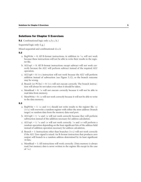
5.1 Combinational logic only: a, b, c, h, i<br />
Sequential logic only: f, g, j<br />
Mixed sequential and combinational: d, e, k<br />
5.2<br />
a. RegWrite = 0: All R-<strong>for</strong>mat instructions, in addition to lw,<br />
will not work<br />
because these instructions will not be able to write their results to the register<br />
file.<br />
b. ALUop1 = 0: All R-<strong>for</strong>mat instructions except subtract will not work correctly<br />
because the ALU will per<strong>for</strong>m subtract instead of the required ALU<br />
operation.<br />
c. ALUop0 = 0: beq instruction will not work because the ALU will per<strong>for</strong>m<br />
addition instead of subtraction (see Figure 5.12), so the branch outcome<br />
may be wrong.<br />
d. Branch (or PCSrc) = 0: beq will not execute correctly. The branch instruction<br />
will always be not taken even when it should be taken.<br />
e. MemRead = 0: lw will not execute correctly because it will not be able to<br />
read data from memory.<br />
f. MemWrite = 0: sw will not work correctly because it will not be able to write<br />
to the data memory.<br />
5.3<br />
a. RegWrite = 1: sw and beq should not write results to the register file. sw<br />
( beq)<br />
will overwrite a random register with either the store address (branch<br />
target) or random data from the memory data read port.<br />
b. ALUop0 = 1: lw and sw will not work correctly because they will per<strong>for</strong>m<br />
subtraction instead of the addition necessary <strong>for</strong> address calculation.<br />
c. ALUop1 = 1: lw and sw will not work correctly. lw and sw will per<strong>for</strong>m a<br />
random operation depending on the least significant bits of the address field<br />
instead of addition operation necessary <strong>for</strong> address calculation.<br />
d. Branch = 1: Instructions other than branches ( beq)<br />
will not work correctly<br />
if the ALU Zero signal is raised. An R-<strong>for</strong>mat instruction that produces zero<br />
output will branch to a random address determined by its least significant<br />
16 bits.<br />
e. MemRead = 1: All instructions will work correctly. (Data memory is always<br />
read, but memory data is never written to the register file except in the case<br />
of lw.)<br />
1
2<br />
<strong>Solutions</strong> <strong>for</strong> <strong>Chapter</strong> 5 <strong>Exercises</strong><br />
5.7<br />
f. MemWrite = 1: Only sw will work correctly. The rest of instructions will<br />
store their results in the data memory, while they should not.<br />
No solution provided.<br />
5.8 A modification to the datapath is necessary to allow the new PC to come<br />
from a register (Read data 1 port), and a new signal (e.g., JumpReg) to control it<br />
through a multiplexor as shown in Figure 5.42.<br />
A new line should be added to the truth table in Figure 5.18 on page 308 to implement<br />
the jr instruction and a new column to produce the JumpReg signal.<br />
5.9 A modification to the data path is necessary (see Figure 5.43) to feed the<br />
shamt field (instruction[10:6]) to the ALU in order to determine the shift amount.<br />
The instruction is in R-Format and is controlled according to the first line in Figure<br />
5.18 on page 308.<br />
The ALU will identify the sll operation by the ALUop field.<br />
Figure 5.13 on page 302 should be modified to recognize the opcode of sll:<br />
the<br />
third line should be changed to 1X1X0000 0010 (to discriminate the add and ssl<br />
functions), and a new line, inserted, <strong>for</strong> example, 1X0X0000 0011 (to define sll<br />
by the 0011 operation code).<br />
5.10 Here one possible lui implementation is presented:<br />
This implementation doesn't need a modification to the datapath. We can use the<br />
ALU to implement the shift operation. The shift operation can be like the one presented<br />
<strong>for</strong> Exercise 5.9, but will make the shift amount as a constant 16. A new line<br />
should be added to the truth table in Figure 5.18 on page 308 to define the new<br />
shift function to the function unit. (Remember two things: first, there is no funct<br />
field in this command; second, the shift operation is done to the immediate field,<br />
not the register input.)<br />
RegDst = 1: To write the ALU output back to the destination register ( $rt).<br />
ALUSrc = 1: Load the immediate field into the ALU.<br />
MemtoReg = 0: Data source is the ALU.<br />
RegWrite = 1: Write results back.<br />
MemRead = 0: No memory read required.<br />
MemWrite = 0: No memory write required.<br />
Branch = 0: Not a branch.<br />
ALUOp = 11: sll operation.<br />
This ALUOp (11) can be translated by the ALU as shl,ALUI1,16 by modifying<br />
the truth table in Figure 5.13 in a way similar to Exercise 5.9.
<strong>Solutions</strong> <strong>for</strong> <strong>Chapter</strong> 5 <strong>Exercises</strong><br />
0<br />
M ux<br />
Add<br />
FIGURE 5.42<br />
0<br />
M<br />
ux<br />
1<br />
ALU<br />
Add<br />
result<br />
4<br />
1<br />
Shift<br />
left 2<br />
JumpReg<br />
RegDst<br />
Branch<br />
MemRead<br />
MemtoReg<br />
ALUOp<br />
MemWrite<br />
ALUSrc<br />
RegWrite<br />
Instruction [31–26]<br />
Control<br />
1<br />
M<br />
ux<br />
Read<br />
data<br />
Address<br />
Instruction [25–21] Read<br />
Read<br />
register 1<br />
address<br />
Read<br />
Instruction [20–16]<br />
data 1<br />
Read<br />
register 2<br />
Zero<br />
Instruction<br />
0<br />
[31–0] ALU<br />
M Read<br />
ALU<br />
Write<br />
0<br />
data 2<br />
result<br />
Instruction<br />
ux<br />
Instruction [15–11] register<br />
M<br />
memory<br />
ux<br />
1<br />
Write<br />
1<br />
data Registers<br />
PC<br />
0<br />
Data<br />
memory<br />
Write<br />
data<br />
ALU<br />
control<br />
16 32<br />
Sign<br />
extend<br />
Instruction [15–0]<br />
Instruction [5–0]<br />
3
4<br />
0<br />
M ux<br />
FIGURE 5.43<br />
<strong>Solutions</strong> <strong>for</strong> <strong>Chapter</strong> 5 <strong>Exercises</strong><br />
Add<br />
1<br />
ALU<br />
Add<br />
result<br />
4<br />
Shift<br />
left 2<br />
RegDst<br />
Branch<br />
MemRead<br />
MemtoReg<br />
ALUOp<br />
MemWrite<br />
ALUSrc<br />
RegWrite<br />
Instruction [31–26]<br />
Control<br />
1<br />
M<br />
ux<br />
Read<br />
data<br />
Address<br />
Instruction [25–21] Read<br />
Read<br />
register 1<br />
address<br />
Read<br />
Instruction [20–16]<br />
data 1<br />
Read<br />
register 2<br />
Zero<br />
Instruction<br />
0<br />
[31–0] ALU<br />
M Read<br />
ALU<br />
Write<br />
0<br />
data 2<br />
result<br />
Instruction<br />
ux<br />
Instruction [15–11] register<br />
M<br />
memory<br />
ux<br />
1<br />
shamt<br />
Write<br />
1<br />
data Registers<br />
PC<br />
0<br />
Data<br />
memory<br />
Write<br />
data<br />
ALU<br />
control<br />
16 32<br />
Sign<br />
extend<br />
Instruction [16 0]<br />
Instruction [8 0]<br />
Instruction [10 6]
<strong>Solutions</strong> <strong>for</strong> <strong>Chapter</strong> 5 <strong>Exercises</strong><br />
5.11 A modification is required <strong>for</strong> the datapath of Figure 5.17 to per<strong>for</strong>m the<br />
autoincrement by adding 4 to the $rs register through an incrementer. Also we<br />
need a second write port to the register file because two register writes are<br />
required <strong>for</strong> this instruction. The new write port will be controlled by a new signal,<br />
"Write 2", and a data port, "Write data 2." We assume that the Write register 2<br />
identifier is always the same as Read register 1 ( $rs).<br />
This way "Write 2" indicates<br />
that there is second write to register file to the register identified by "Read register<br />
1," and the data is fed through Write data 2.<br />
A new line should be added to the truth table in Figure 5.18 <strong>for</strong> the l_inc command<br />
as follows:<br />
RegDst = 0: First write to $rt.<br />
ALUSrc = 1: Address field <strong>for</strong> address calculation.<br />
MemtoReg = 1: Write loaded data from memory.<br />
RegWrite = 1: Write loaded data into $rt.<br />
MemRead = 1: Data memory read.<br />
MemWrite = 0: No memory write required.<br />
Branch = 0: Not a branch, output from the PCSrc controlled mux ignored.<br />
ALUOp = 00: Address calculation.<br />
Write2 = 1: Second register write (to $rs).<br />
Such a modification of the register file architecture may not be required <strong>for</strong> a multiple-cycle<br />
implementation, since multiple writes to the same port can occur on<br />
different cycles.<br />
5.12 This instruction requires two writes to the register file. The only way to<br />
implement it is to modify the register file to have two write ports instead of one.<br />
5.13 From Figure 5.18, the MemtoReg control signal looks identical to both signals,<br />
except <strong>for</strong> the don't care entries which have different settings <strong>for</strong> the other<br />
signals. A don't care can be replaced by any signal; hence both signals can substitute<br />
<strong>for</strong> the MemtoReg signal.<br />
Signals ALUSrc and MemRead differ in that sw sets ALSrc (<strong>for</strong> address calculation)<br />
and resets MemRead (writes memory: can't have a read and a write in the<br />
same cycle), so they can't replace each other. If a read and a write operation can<br />
take place in the same cycle, then ALUSrc can replace MemRead, and hence we<br />
can eliminate the two signals MemtoReg and MemRead from the control system.<br />
Insight: MemtoReg directs the memory output into the register file; this happens<br />
only in loads. Because sw and beq don't produce output, they don't write to the<br />
5
6<br />
<strong>Solutions</strong> <strong>for</strong> <strong>Chapter</strong> 5 <strong>Exercises</strong><br />
register file (Regwrite = 0), and the setting of MemtoReg is hence a don't care. The<br />
important setting <strong>for</strong> a signal that replaces the MemtoReg signal is that it is set <strong>for</strong><br />
lw (Mem->Reg), and reset <strong>for</strong> R-<strong>for</strong>mat (ALU->Reg), which is the case <strong>for</strong> the<br />
ALUSrc (different sources <strong>for</strong> ALU identify lw from R-<strong>for</strong>mat) and MemRead ( lw<br />
reads memory but not R-<strong>for</strong>mat).<br />
5.14<br />
swap $rs,$rt can be implemented by<br />
addi $rd,$rs,0<br />
addi $rs,$rt,0<br />
addi $rt,$rd,0<br />
if there is an available register $rd<br />
or<br />
sw $rs,temp($r0)<br />
addi $rs,$rt,0<br />
lw $rt,temp($r0)<br />
if not.<br />
Software takes three cycles, and hardware takes one cycle. Assume Rs is the ratio of<br />
swaps in the code mix and that the base CPI is 1:<br />
Average MIPS time per instruction = Rs * 3 * T + (1 – Rs)<br />
* 1 * T = (2Rs<br />
+ 1) * T<br />
Complex implementation time = 1.1 * T<br />
If swap instructions are greater than 5% of the instruction mix, then a hardware<br />
implementation would be preferable.<br />
5.27<br />
l_incr $rt,Address($rs) can be implemented as<br />
lw $rt,Address($rs)<br />
addi $rs,$rs,1<br />
Two cycles instead of one. This time the hardware implementation is more efficient<br />
if the load with increment instruction constitute more than 10% of the<br />
instruction mix.<br />
5.28 Load instructions are on the critical path that includes the following functional<br />
units: instruction memory, register file read, ALU, data memory, and register<br />
file write. Increasing the delay of any of these units will increase the clock<br />
period of this datapath. The units that are outside this critical path are the two
<strong>Solutions</strong> <strong>for</strong> <strong>Chapter</strong> 5 <strong>Exercises</strong><br />
adders used <strong>for</strong> PC calculation (PC + 4 and PC + Immediate field), which produce<br />
the branch outcome.<br />
Based on the numbers given on page 315, the sum of the the two adder’s delay can<br />
tolerate delays up to 400 more ps.<br />
Any reduction in the critical path components will lead to a reduction in the clock<br />
period.<br />
5.29<br />
a. RegWrite = 0: All R-<strong>for</strong>mat instructions, in addition to lw,<br />
will not work<br />
because these instructions will not be able to write their results to the register<br />
file.<br />
b. MemRead = 0: None of the instructions will run correctly because instructions<br />
will not be fetched from memory.<br />
c. MemWrite = 0: sw will not work correctly because it will not be able to write<br />
to the data memory.<br />
d. IRWrite = 0: None of the instructions will run correctly because instructions<br />
fetched from memory are not properly stored in the IR register.<br />
e. PCWrite = 0: Jump instructions will not work correctly because their target<br />
address will not be stored in the PC.<br />
f. PCWriteCond = 0: Taken branches will not execute correctly because their<br />
target address will not be written into the PC.<br />
5.30<br />
a. RegWrite = 1: Jump and branch will write their target address into the register<br />
file. sw will write the destination address or a random value into the register<br />
file.<br />
b. MemRead = 1: All instructions will work correctly. Memory will be read all<br />
the time, but IRWrite and IorD will safeguard this signal.<br />
c. MemWrite = 1: All instructions will not work correctly. Both instruction<br />
and data memories will be written over by the contents of register B.<br />
d. IRWrite = 1: lw will not work correctly because data memory output will be<br />
translated as instructions.<br />
e. PCWrite = 1: All instructions except jump will not work correctly. This signal<br />
should be raised only at the time the new PC address is ready (PC + 4 at<br />
cycle 1 and jump target in cycle 3). Raising this signal all the time will corrupt<br />
the PC by either ALU results of R-<strong>for</strong>mat, memory address of lw/<br />
sw, or<br />
target address of conditional branch, even when they should not be taken.<br />
f. PCWriteCond = 1: Instructions other than branches (beq) will not work<br />
correctly if they raise the ALU's Zero signal. An R-<strong>for</strong>mat instruction that<br />
produces zero output will branch to a random address determined by their<br />
least significant 16 bits.<br />
7
8 <strong>Solutions</strong> <strong>for</strong> <strong>Chapter</strong> 5 <strong>Exercises</strong><br />
5.31 RegDst can be replaced by ALUSrc, MemtoReg, MemRead, ALUop1.<br />
MemtoReg can be replaced by RegDst, ALUSrc, MemRead, or ALUOp1.<br />
Branch and ALUOp0 can replace each other.<br />
5.32 We use the same datapath, so the immediate field shift will be done inside<br />
the ALU.<br />
1. Instruction fetch step: This is the same (IR
<strong>Solutions</strong> <strong>for</strong> <strong>Chapter</strong> 5 <strong>Exercises</strong> 9<br />
3. Now the final <strong>for</strong>m of the immediate value is ready to be loaded into the<br />
register file. The MemtoReg control signal has to be modified in order to<br />
allow its multiplexor to select the immediate upper field as the write data<br />
source. We can assume that this signal becomes a 2-bit control signal, and<br />
that the value 2 will select the immediate upper field.<br />
Figure 5.44 plots the modified datapath.<br />
The first two cycles are identical to the FSM of Figure 5.38. By the end of the second<br />
cycle, the FSM will recognize the opcode. We add the Op = 'lui', a new transition<br />
condition from state 1 to a new state 10. In this state we store the immediate<br />
upper field into the register file by these signals: RedDst = 0, RegWrite, MemtoReg<br />
= 2. State 10 will make the transition back to state 0 after its completion.<br />
5.34 We can use the same datapath.<br />
1. Instruction fetch: Unchanged (IR
10 <strong>Solutions</strong> <strong>for</strong> <strong>Chapter</strong> 5 <strong>Exercises</strong><br />
PCSource<br />
ALUOp<br />
Outputs<br />
FIGURE 5.44<br />
ALUSrcB<br />
Control<br />
ALUSrcA<br />
RegWrite<br />
Op<br />
[5–0]<br />
RegDst<br />
PCWriteCond<br />
PCWrite<br />
IorD<br />
MemRead<br />
MemWrite<br />
MemtoReg<br />
IRWrite<br />
Jump<br />
address<br />
[31–0]<br />
26 Shift 28<br />
left 2<br />
Instruction [25-0]<br />
PC [31–28]<br />
Zero<br />
ALUOut<br />
ALU ALU<br />
result<br />
M ux<br />
Instruction<br />
[31–26]<br />
PC 0<br />
Instruction<br />
Read<br />
0<br />
M<br />
ux Address<br />
[25–21]<br />
register 1<br />
M<br />
Read<br />
A<br />
ux<br />
1<br />
Instruction<br />
data 1<br />
Memory<br />
Read<br />
[20–16]<br />
1<br />
register 2<br />
MemData<br />
0<br />
Instruction<br />
M Registers<br />
[15–0] Instruction ux Write<br />
Read<br />
Write<br />
[15–11] register<br />
data 2 B 0<br />
data<br />
Instruction<br />
1<br />
4 1<br />
register<br />
Write<br />
0<br />
data<br />
2<br />
Instruction<br />
M 3<br />
[15–0]<br />
ux<br />
[L,16[0]<br />
1<br />
ALU<br />
control<br />
Shift<br />
left 2<br />
16 32<br />
Sign<br />
extend<br />
Memory<br />
data<br />
register<br />
Instruction [5–0]
<strong>Solutions</strong> <strong>for</strong> <strong>Chapter</strong> 5 <strong>Exercises</strong> 11<br />
read and RegRead is held stable (because A always writes). Alternatively, you could<br />
decide to read A first because it may be needed to calculate an address. You could<br />
then postpone reading B until state 2 and avoid adding an extra cycle <strong>for</strong> the load<br />
and store instructions. An extra cycle would be needed <strong>for</strong> the branch and R-type<br />
instructions.<br />
5.36 Effective CPI = Sum(operation frequency * operation latency)<br />
MIPS = Frequency/CPIeffective<br />
Instruction Frequency M1 M2 M3<br />
Loads CPI 25% 5 4 3<br />
Stores CPI 13% 4 4 3<br />
R-type CPI 47% 4 3 3<br />
Branch/jmp CPI 15% 3 3 3<br />
Effective CPI 4.1 3.38 3<br />
MIPS 976 946 933<br />
From the results above, the penalty imposed on frequency (<strong>for</strong> all instructions)<br />
exceeds the gains attained through the CPI reduction. M1 is the fastest machine.<br />
The more the load instructions in the instruction mix, the more the CPI gain we<br />
can get <strong>for</strong> the M2 and M3 machines. In the extreme case we have all instructions<br />
loads, M1 MIPS = 800, M2 MIPS = 300, and M3 MIPS = 933.3, so M3 becomes<br />
the best machine in such a case.<br />
5.37 Effective CPI = Sum(operation frequency * operation latency)<br />
MIPS = Frequency/CPIeffective<br />
Instruction Frequency 2.8 GHz CPI 5.6 GHz CPI 6.4 GHz CPI<br />
Loads CPI 26% 5 6 7<br />
Stores CPI 10% 4 5 6<br />
R-type CPI 49% 4 4 5<br />
Branch/jmp CPI 15% 3 3 4<br />
Effective CPI 4.11 4.47 5.47<br />
MIPS 1167.9 1250 1170.0
12 <strong>Solutions</strong> <strong>for</strong> <strong>Chapter</strong> 5 <strong>Exercises</strong><br />
The two-cycle implementation increases the frequency, which benefits all instructions,<br />
and penalizes only loads and stores. The per<strong>for</strong>mance improvement is 7%<br />
relative to the original implementation.<br />
Further increase of the clock frequency by increasing the instruction fetch time<br />
into two cycles will penalize all instructions and will reduce the per<strong>for</strong>mance to<br />
about the same as that of the 4.8 GHz base per<strong>for</strong>mance. Such implementation<br />
hurts the CPI more than the gain it brings through frequency increase and should<br />
not be implemented.<br />
5.38<br />
slt $t4, $zero, $t3<br />
beg $t4, $zero, exit<br />
cmpr: lw $t4, 0($t1)<br />
lw $t5, 0($t5)<br />
bne $t4, $t5, done<br />
addi $t3, $t3, –1<br />
addi $t1, $t1, 4<br />
addi $t2, $t2, 4<br />
bne $t3, $zero, cmpr<br />
exit addi $t1, $zero, $zero<br />
done:<br />
To compare two 100-work blocks we'll per<strong>for</strong>m at most one sit 200 loads, 300<br />
adds, and 201 branches = 803 instructions (if the two blocks are equal). Using<br />
this chapter's multicycle implementation, this will take 4 cycles <strong>for</strong> sit 1000 cycles<br />
<strong>for</strong> loads, 1200 cycles <strong>for</strong> adds, and 603 cycles <strong>for</strong> branches. The total cycles = 2811<br />
cycles.<br />
5.39 No solution provided.<br />
5.49 No solution provided.<br />
5.50 The exception cause can be represented through the status "cause" register,<br />
which records the reason code <strong>for</strong> the exception. The instruction position at<br />
which the exception occur is identified by saving it in the Exception Program<br />
Counter (EPC) register.<br />
Execution can be restarted <strong>for</strong> some exceptions like overflow, system call request,<br />
or external I/O device interrupt by restarting execution at the EPC after handling<br />
the exception.<br />
Other exceptions are not restartable and program has to terminate. Examples of<br />
this are invalid instructions (which can actually be restartable if defined as NOP<br />
by the hardware), power/hardware failure, and divide by zero. In such a case, an<br />
error message can be produced, and program termination takes place.
<strong>Solutions</strong> <strong>for</strong> <strong>Chapter</strong> 5 <strong>Exercises</strong> 13<br />
5.51<br />
a. Divide by zero exception can be detected in the ALU in cycle 3, be<strong>for</strong>e executing<br />
the divide instruction.<br />
b. Overflow can be hardware detected after the completion of the ALU operation.<br />
This is done in cycle 4 (see Figure 5.40)<br />
c. Invalid opcode can be detected by the end of cycle 2 (see Figure 5.40).<br />
d. This is an asynchronous exception event that can occur at any cycle. We can<br />
design this machine to test <strong>for</strong> this condition either at a specific cycle (and<br />
then the exception can take place only in a specific stage), or check in every<br />
cycle (and then this exception can occur at any processor stage).<br />
e. Check <strong>for</strong> instruction memory address can be done at the time we update<br />
the PC. This can be done in cycle 1.<br />
f. Check <strong>for</strong> data memory address can be done after address calculation at the<br />
end of cycle 3.<br />
5.53 No solution provided.<br />
5.57 No solution provided.<br />
5.58 a) will assign the same value (2) to both A and B.<br />
b) will swap A and B (A = 2 and B = 1).<br />
5.59<br />
module ALUControl (ALUOp, FuncCode, ALUCtl);<br />
input ALUOp[1:0], FuncCode[5:0];<br />
output ALUCtl[3:0];<br />
if(ALUOp == 2'b 00)<br />
ALUCtl = 4'b 0010;<br />
if(ALUOp == 2'b 01)<br />
ALUCtl = 4'b 0110;<br />
if(ALUOp == 2'b 10) begin<br />
case(FuncCode)<br />
6'b 100000: ALUCtl = 4'b 0010;<br />
6'b 100010: ALUCtl = 4'b 0110;<br />
6'b 100100: ALUCtl = 4'b 0000;<br />
6'b 100101: ALUCtl = 4'b 0001;
14 <strong>Solutions</strong> <strong>for</strong> <strong>Chapter</strong> 5 <strong>Exercises</strong><br />
6'b 101010: ALUCtl = 4'b 0111;<br />
default ALUCtl = 4'b xxxx;<br />
endcase<br />
end<br />
endmodule<br />
5.60<br />
// Register File<br />
module RegisterFile (Read1,Read2,Writereg,Writedata,Regwrite,<br />
Data1Data2,clock);<br />
input [5:0] Read1,Read2,Writereg; // the registers numbers to read<br />
or write<br />
input [31:0] Writedata; // data to write<br />
input RegWrite, // The write control<br />
clock; // the clock to trigger writes<br />
output [31:0] Data1, Data2; // the register values read;<br />
reg [31:0] RF [31:0]; // 32 registers each 32 bits long<br />
initial RF[0] = 32'h 00000000; // Initialize all registers to 0<br />
always begin<br />
Data1
<strong>Solutions</strong> <strong>for</strong> <strong>Chapter</strong> 5 <strong>Exercises</strong> 15<br />
default ALUCtl = 4'b xxxx; //can report an error, or debug<br />
in<strong>for</strong>mation<br />
endcase<br />
end<br />
endmodule<br />
//ALU<br />
module MIPSALU (ALUctl, A, B, ALUOut, Zero);<br />
input [3:0] ALUctl;<br />
input [31:0] A,B;<br />
output [31:0] ALUOut;<br />
output Zero;<br />
assign Zero = (ALUOut==0); //Zero is true if ALUOut is 0<br />
always @(ALUctl, A, B) begin //reevaluate if these change<br />
case (Aluctl)<br />
0: ALUOut
16 <strong>Solutions</strong> <strong>for</strong> <strong>Chapter</strong> 5 <strong>Exercises</strong><br />
//This represents every thing in Figure 5.19 on page 309 except the<br />
"control block"<br />
//Which decodes the opcode, and generate the control signals<br />
accordingly<br />
module DataPath(start,RegDst,Branch,MemRead,MemtoReg,ALUOp,Mem-<br />
Write,ALUSrc,RegWrite,opcode,clock)<br />
input [31:0] start; //PC initial value<br />
input RegDst,Branch,MemRead,MemtoReg,<br />
ALUOp,MemWrite,ALUSrc,RegWrite,clock;<br />
input [1:0] ALUOp;<br />
output [5:0] opcode;<br />
initial begin //initialize PC and Memories<br />
PC = start;<br />
IMemory = PROGRAM;<br />
DMemory = DATA;<br />
end<br />
reg [31:0] PC, IMemory[0:1023], DMemory[0:1023];<br />
wire [31:0] SignExtendOffset, PCOffset, PCValue, ALUResultOut,<br />
IAddress, DAddress, IMemOut, DmemOut, DWriteData, Instruction,<br />
RWriteData, DreadData, ALUAin, ALUBin;<br />
wire [3:0] ALUctl;<br />
wire Zero;<br />
wire [5:0] WriteReg;<br />
//Instruction fields, to improve code readability<br />
wire [5:0] funct;<br />
wire [4:0] rs, rt, rd, shamt;<br />
wire [15:0] offset;<br />
ALUControl alucontroller(ALUOp,Instruction[5:0],ALUctl);<br />
//ALU control<br />
MIPSALU ALU(ALUctl, ALUAin, ALUBin, ALUResultOut, Zero);<br />
RegisterFile REG(rs, rt, WriteReg, RWriteData, ALUAin, DWriteData,<br />
clock);<br />
Mult2to1 regdst (rt, rd, RegDst, RegWrite),<br />
alusrc (DWriteData, SignExtendOffset, ALUSrc, ALUBin),<br />
pcsrc (PC+4, PC+4+PCOffset, Branch & Zero, PCValue);<br />
assign {opcode, rs, rt, rd, shamt, funct} = Instruction;<br />
assign offset = Instruction[15:0];<br />
assign SignExtendOffset = {16{offset[15]},offset}; //sign-extend<br />
lower 16 bits;<br />
assign PCOffset = SignExtendOffset
<strong>Solutions</strong> <strong>for</strong> <strong>Chapter</strong> 5 <strong>Exercises</strong> 17<br />
always @(negedge clock) begin<br />
Instruction = IMemory[PC];<br />
PC
18 <strong>Solutions</strong> <strong>for</strong> <strong>Chapter</strong> 5 <strong>Exercises</strong><br />
5.61 We implement the add shift functionality to the ALU using the Verilog code<br />
provided in B.22 in Appendix B. The 32-bit multiply execution takes 32 cycles to<br />
complete, so the instruction takes a total of 35 cycles. Assume the ALU control<br />
recognizes the multiply code correctly.<br />
We follow the CD Verilog code, but we add the following:<br />
case(state)<br />
.<br />
.<br />
3: begin //Execution starts at cycle 3<br />
state=4<br />
.<br />
.<br />
case(opcode==6'b 0)<br />
.<br />
.<br />
MPYU: begin<br />
// issue load command to the multiplier<br />
{RegDst,ALUSrc,MemtoReg,RegWrite,MemRead,<br />
MemWrite,Branch,ALUOp}= 9'b 1001000110;//R-Format same<br />
command. Alu should now recognize the Func Field<br />
end<br />
.<br />
.<br />
35: // After 32 cycles the multiplication<br />
results are available in the 32-bit Product output of<br />
the ALU. Write the high order and low order words in<br />
this and the next cycle.<br />
case(opcode==6'b 0) case (IR[5:0])<br />
.<br />
.<br />
MPYU: begin<br />
Regs[hi]=RegH<br />
end
<strong>Solutions</strong> <strong>for</strong> <strong>Chapter</strong> 5 <strong>Exercises</strong> 19<br />
34:<br />
case(opcode==6'b 0) case (IR[5:0])<br />
.<br />
.<br />
MPYU: begin<br />
Regs[lo]=RegL<br />
end<br />
end<br />
5.62 We add the divide functionality to the ALU using the code of B.23. The rest<br />
of the solution is almost exactly the same as the answer to Exercise 5.61.<br />
5.63 No solution provided<br />
5.64 No solution provided.<br />
5.65 No solution provided.<br />
5.66 No solution provided.