LF198/LF298/LF398, LF198A/LF398A Monolithic Sample-and-Hold ...
LF198/LF298/LF398, LF198A/LF398A Monolithic Sample-and-Hold ...
LF198/LF298/LF398, LF198A/LF398A Monolithic Sample-and-Hold ...

You also want an ePaper? Increase the reach of your titles
YUMPU automatically turns print PDFs into web optimized ePapers that Google loves.
<strong>LF198</strong>/<strong>LF298</strong>/<strong>LF398</strong>, <strong>LF198</strong>A/<strong>LF398</strong>A<br />
<strong>Monolithic</strong> <strong>Sample</strong>-<strong>and</strong>-<strong>Hold</strong> Circuits<br />
General Description<br />
The <strong>LF198</strong>/<strong>LF298</strong>/<strong>LF398</strong> are monolithic sample-<strong>and</strong>-hold<br />
circuits which utilize BI-FET technology to obtain ultra-high<br />
dc accuracy with fast acquisition of signal <strong>and</strong> low droop<br />
rate. Operating as a unity gain follower, dc gain accuracy is<br />
0.002% typical <strong>and</strong> acquisition time is as low as 6 µs to<br />
0.01%. A bipolar input stage is used to achieve low offset<br />
voltage <strong>and</strong> wide b<strong>and</strong>width. Input offset adjust is accomplished<br />
with a single pin, <strong>and</strong> does not degrade input offset<br />
drift. The wide b<strong>and</strong>width allows the <strong>LF198</strong> to be included inside<br />
the feedback loop of 1 MHz op amps without having stability<br />
problems. Input impedance of 10 10Ω allows high<br />
source impedances to be used without degrading accuracy.<br />
P-channel junction FET’s are combined with bipolar devices<br />
in the output amplifier to give droop rates as low as 5 mV/min<br />
witha1µFhold capacitor. The JFET’s have much lower<br />
noise than MOS devices used in previous designs <strong>and</strong> do<br />
not exhibit high temperature instabilities. The overall design<br />
guarantees no feed-through from input to output in the hold<br />
mode, even for input signals equal to the supply voltages.<br />
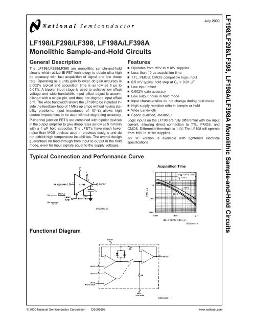
Typical Connection <strong>and</strong> Performance Curve<br />
Functional Diagram<br />
DS005692-32<br />
Features<br />
n Operates from ±5V to ±18V supplies<br />
n Less than 10 µs acquisition time<br />
n TTL, PMOS, CMOS compatible logic input<br />
n 0.5 mV typical hold step at Ch = 0.01 µF<br />
n Low input offset<br />
n 0.002% gain accuracy<br />
n Low output noise in hold mode<br />
n Input characteristics do not change during hold mode<br />
n High supply rejection ratio in sample or hold<br />
n Wide b<strong>and</strong>width<br />
n Space qualified, JM38510<br />
Logic inputs on the <strong>LF198</strong> are fully differential with low input<br />
current, allowing direct connection to TTL, PMOS, <strong>and</strong><br />
CMOS. Differential threshold is 1.4V. The <strong>LF198</strong> will operate<br />
from ±5V to ±18V supplies.<br />
An “A” version is available with tightened electrical<br />
specifications.<br />
Acquisition Time<br />
DS005692-1<br />
DS005692-16<br />
July 2000<br />
© 2000 National Semiconductor Corporation DS005692 www.national.com<br />
<strong>LF198</strong>/<strong>LF298</strong>/<strong>LF398</strong>, <strong>LF198</strong>A/<strong>LF398</strong>A <strong>Monolithic</strong> <strong>Sample</strong>-<strong>and</strong>-<strong>Hold</strong> Circuits
<strong>LF198</strong>/<strong>LF298</strong>/<strong>LF398</strong>, <strong>LF198</strong>A/<strong>LF398</strong>A<br />
Absolute Maximum Ratings (Note 1)<br />
If Military/Aerospace specified devices are required,<br />
please contact the National Semiconductor Sales Office/<br />
Distributors for availability <strong>and</strong> specifications.<br />
Supply Voltage ±18V<br />
Power Dissipation (Package<br />
Limitation) (Note 2) 500 mW<br />
Operating Ambient Temperature Range<br />
<strong>LF198</strong>/<strong>LF198</strong>A −55˚C to +125˚C<br />
<strong>LF298</strong> −25˚C to +85˚C<br />
<strong>LF398</strong>/<strong>LF398</strong>A 0˚C to +70˚C<br />
Storage Temperature Range −65˚C to +150˚C<br />
Input Voltage Equal to Supply Voltage<br />
Logic To Logic Reference<br />
Differential Voltage (Note 3) +7V, −30V<br />
Output Short Circuit Duration Indefinite<br />
<strong>Hold</strong> Capacitor Short<br />
Circuit Duration 10 sec<br />
Lead Temperature (Note 4)<br />
H package (Soldering, 10 sec.) 260˚C<br />
N package (Soldering, 10 sec.) 260˚C<br />
M package:<br />
Vapor Phase (60 sec.) 215˚C<br />
Infrared (15 sec.) 220˚C<br />
Thermal Resistance (θ JA) (typicals)<br />
H package 215˚C/W (Board mount in still air)<br />
85˚C/W (Board mount in<br />
400LF/min air flow)<br />
N package 115˚C/W<br />
M package 106˚C/W<br />
θ JC (H package, typical) 20˚C/W<br />
Electrical Characteristics<br />
The following specifcations apply for −VS + 3.5V ≤ VIN ≤ +VS − 3.5V, +VS = +15V, −VS = −15V, TA =Tj= 25˚C, C h = 0.01 µF,<br />
RL =10kΩ, LOGIC REFERENCE = 0V, LOGIC HIGH = 2.5V, LOGIC LOW = 0V unless otherwise specified.<br />
Parameter Conditions <strong>LF198</strong>/<strong>LF298</strong> <strong>LF398</strong> Units<br />
Min Typ Max Min Typ Max<br />
Input Offset Voltage, (Note 5) Tj = 25˚C 1 3 2 7 mV<br />
Full Temperature Range 5 10 mV<br />
Input Bias Current, (Note 5) Tj = 25˚C 5 25 10 50 nA<br />
Full Temperature Range 75 100 nA<br />
Input Impedance Tj = 25˚C 10 10 10 10 Ω<br />
Gain Error Tj = 25˚C, R L = 10k 0.002 0.005 0.004 0.01 %<br />
Full Temperature Range 0.02 0.02 %<br />
Feedthrough Attenuation Ratio<br />
at 1 kHz<br />
Tj = 25˚C, C h = 0.01 µF 86 96 80 90 dB<br />
Output Impedance Tj = 25˚C, “HOLD” mode 0.5 2 0.5 4 Ω<br />
Full Temperature Range 4 6 Ω<br />
“HOLD” Step, (Note 6) Tj = 25˚C, C h = 0.01 µF, VOUT = 0 0.5 2.0 1.0 2.5 mV<br />
Supply Current, (Note 5) Tj≥25˚C 4.5 5.5 4.5 6.5 mA<br />
Logic <strong>and</strong> Logic Reference Input<br />
Current<br />
Tj = 25˚C 2 10 2 10 µA<br />
Leakage Current into <strong>Hold</strong> Tj = 25˚C, (Note 7) 30 100 30 200 pA<br />
Capacitor (Note 5) <strong>Hold</strong> Mode<br />
Acquisition Time to 0.1% ΔVOUT = 10V, Ch = 1000 pF 4 4 µs<br />
Ch = 0.01 µF 20 20 µs<br />
<strong>Hold</strong> Capacitor Charging Current VIN−VOUT =2V 5 5 mA<br />
Supply Voltage Rejection Ratio VOUT = 0 80 110 80 110 dB<br />
Differential Logic Threshold Tj = 25˚C 0.8 1.4 2.4 0.8 1.4 2.4 V<br />
Input Offset Voltage, (Note 5) Tj = 25˚C 1 1 2 2 mV<br />
Full Temperature Range 2 3 mV<br />
Input Bias Current, (Note 5) Tj = 25˚C 5 25 10 25 nA<br />
Full Temperature Range 75 50 nA<br />
www.national.com 2
Electrical Characteristics<br />
The following specifcations apply for −VS + 3.5V ≤ VIN ≤ +VS − 3.5V, +VS = +15V, −VS = −15V, TA =Tj= 25˚C, C h = 0.01 µF,<br />
RL =10kΩ, LOGIC REFERENCE = 0V, LOGIC HIGH = 2.5V, LOGIC LOW = 0V unless otherwise specified.<br />
Parameter Conditions <strong>LF198</strong>A <strong>LF398</strong>A Units<br />
Min Typ Max Min Typ Max<br />
Input Impedance Tj = 25˚C 10 10 10 10 Ω<br />
Gain Error Tj = 25˚C, R L = 10k 0.002 0.005 0.004 0.005 %<br />
Full Temperature Range 0.01 0.01 %<br />
Feedthrough Attenuation Ratio<br />
at 1 kHz<br />
Tj = 25˚C, C h = 0.01 µF 86 96 86 90 dB<br />
Output Impedance Tj = 25˚C, “HOLD” mode 0.5 1 0.5 1 Ω<br />
Full Temperature Range 4 6 Ω<br />
“HOLD” Step, (Note 6) Tj = 25˚C, C h = 0.01µF, VOUT = 0 0.5 1 1.0 1 mV<br />
Supply Current, (Note 5) Tj≥25˚C 4.5 5.5 4.5 6.5 mA<br />
Logic <strong>and</strong> Logic Reference Input<br />
Current<br />
Tj = 25˚C 2 10 2 10 µA<br />
Leakage Current into <strong>Hold</strong> Tj = 25˚C, (Note 7) 30 100 30 100 pA<br />
Capacitor (Note 5) <strong>Hold</strong> Mode<br />
Acquisition Time to 0.1% ΔVOUT = 10V, Ch = 1000 pF 4 6 4 6 µs<br />
Ch = 0.01 µF 20 25 20 25 µs<br />
<strong>Hold</strong> Capacitor Charging Current VIN−VOUT =2V 5 5 mA<br />
Supply Voltage Rejection Ratio VOUT = 0 90 110 90 110 dB<br />
Differential Logic Threshold Tj = 25˚C 0.8 1.4 2.4 0.8 1.4 2.4 V<br />
Note 1: “Absolute Maximum Ratings” indicate limits beyond which damage to the device may occur. Operating Ratings indicate conditions for which the device is<br />
functional, but do not guarantee specific performance limits.<br />
Note 2: The maximum power dissipation must be derated at elevated temperatures <strong>and</strong> is dictated by TJMAX, θJA, <strong>and</strong> the ambient temperature, TA. The maximum<br />
allowable power dissipation at any temperature is PD =(TJMAX −TA)/θJA, or the number given in the Absolute Maximum Ratings, whichever is lower. The maximum<br />
junction temperature, TJMAX, for the <strong>LF198</strong>/<strong>LF198</strong>A is 150˚C; for the <strong>LF298</strong>, 115˚C; <strong>and</strong> for the <strong>LF398</strong>/<strong>LF398</strong>A, 100˚C.<br />
Note 3: Although the differential voltage may not exceed the limits given, the common-mode voltage on the logic pins may be equal to the supply voltages without<br />
causing damage to the circuit. For proper logic operation, however, one of the logic pins must always be at least 2V below the positive supply <strong>and</strong> 3V above the negative<br />
supply.<br />
Note 4: See AN-450 “Surface Mounting Methods <strong>and</strong> their effects on Product Reliability” for other methods of soldering surface mount devices.<br />
Note 5: These parameters guaranteed over a supply voltage range of ±5 to±18V, <strong>and</strong> an input range of −VS + 3.5V ≤ VIN ≤ +VS − 3.5V.<br />
Note 6: <strong>Hold</strong> step is sensitive to stray capacitive coupling between input logic signals <strong>and</strong> the hold capacitor. 1 pF, for instance, will create an additional 0.5 mV step<br />
with a 5V logic swing <strong>and</strong> a 0.01µF hold capacitor. Magnitude of the hold step is inversely proportional to hold capacitor value.<br />
Note 7: Leakage current is measured at a junction temperature of 25˚C. The effects of junction temperature rise due to power dissipation or elevated ambient c an<br />
be calculated by doubling the 25˚C value for each 11˚C increase in chip temperature. Leakage is guaranteed over full input signal range.<br />
Note 8: A military RETS electrical test specification is available on request. The <strong>LF198</strong> may also be procured to St<strong>and</strong>ard Military Drawing #5962-8760801GA or to<br />
MIL-STD-38510 part ID JM38510/12501SGA.<br />
Typical Performance Characteristics<br />
Aperture Time<br />
(Note 9)<br />
Note 9: See Definition of Terms<br />
DS005692-17<br />
Dielectric Absorption<br />
Error in <strong>Hold</strong> Capacitor<br />
3<br />
DS005692-18<br />
Dynamic Sampling Error<br />
DS005692-19<br />
www.national.com<br />
<strong>LF198</strong>/<strong>LF298</strong>/<strong>LF398</strong>, <strong>LF198</strong>A/<strong>LF398</strong>A
<strong>LF198</strong>/<strong>LF298</strong>/<strong>LF398</strong>, <strong>LF198</strong>A/<strong>LF398</strong>A<br />
Typical Performance Characteristics (Continued)<br />
Output Droop Rate<br />
Leakage Current into <strong>Hold</strong><br />
Capacitor<br />
Power Supply Rejection<br />
Note 10: See Definition<br />
DS005692-20<br />
DS005692-23<br />
DS005692-26<br />
<strong>Hold</strong> Step<br />
Phase <strong>and</strong> Gain (Input to<br />
Output, Small Signal)<br />
Output Short Circuit Current<br />
www.national.com 4<br />
DS005692-21<br />
DS005692-24<br />
DS005692-27<br />
“<strong>Hold</strong>” Settling Time<br />
(Note 10)<br />
Gain Error<br />
Output Noise<br />
DS005692-22<br />
DS005692-25<br />
DS005692-28
Typical Performance Characteristics (Continued)<br />
Input Bias Current<br />
Output Transient at Start<br />
of <strong>Sample</strong> Mode<br />
DS005692-29<br />
Logic Input Configurations<br />
Threshold = 1.4V<br />
Feedthrough Rejection Ratio<br />
(<strong>Hold</strong> Mode)<br />
DS005692-12<br />
DS005692-33<br />
DS005692-30<br />
Output Transient at Start<br />
of <strong>Hold</strong> Mode<br />
TTL & CMOS<br />
3V ≤ V LOGIC (Hi State) ≤ 7V<br />
Threshold = 1.4V<br />
*Select for 2.8V at pin 8<br />
5<br />
<strong>Hold</strong> Step vs Input Voltage<br />
DS005692-13<br />
DS005692-34<br />
DS005692-31<br />
www.national.com<br />
<strong>LF198</strong>/<strong>LF298</strong>/<strong>LF398</strong>, <strong>LF198</strong>A/<strong>LF398</strong>A
<strong>LF198</strong>/<strong>LF298</strong>/<strong>LF398</strong>, <strong>LF198</strong>A/<strong>LF398</strong>A<br />
Logic Input Configurations (Continued)<br />
Threshold = 0.6 (V + ) + 1.4V<br />
Threshold ≈ +4V<br />
Application Hints<br />
DS005692-35<br />
DS005692-37<br />
<strong>Hold</strong> Capacitor<br />
<strong>Hold</strong> step, acquisition time, <strong>and</strong> droop rate are the major<br />
trade-offs in the selection of a hold capacitor value. Size <strong>and</strong><br />
cost may also become important for larger values. Use of the<br />
curves included with this data sheet should be helpful in selecting<br />
a reasonable value of capacitance. Keep in mind that<br />
for fast repetition rates or tracking fast signals, the capacitor<br />
drive currents may cause a significant temperature rise in<br />
the <strong>LF198</strong>.<br />
A significant source of error in an accurate sample <strong>and</strong> hold<br />
circuit is dielectric absorption in the hold capacitor. A mylar<br />
cap, for instance, may “sag back” up to 0.2% after a quick<br />
change in voltage. A long sample time is required before the<br />
circuit can be put back into the hold mode with this type of<br />
capacitor. Dielectrics with very low hysteresis are polystyrene,<br />
polypropylene, <strong>and</strong> Teflon. Other types such as mica<br />
<strong>and</strong> polycarbonate are not nearly as good. The advantage of<br />
polypropylene over polystyrene is that it extends the maximum<br />
ambient temperature from 85˚C to 100˚C. Most ceramic<br />
capacitors are unusable with > 1% hysteresis. Ceramic<br />
“NPO” or “COG” capacitors are now available for<br />
125˚C operation <strong>and</strong> also have low dielectric absorption. For<br />
more exact data, see the curve Dielectric Absorption Error.<br />
The hysteresis numbers on the curve are final values, taken<br />
after full relaxation. The hysteresis error can be significantly<br />
CMOS<br />
7V ≤ V LOGIC (Hi State) ≤ 15V<br />
Threshold = 0.6 (V + ) − 1.4V<br />
Op Amp Drive<br />
www.national.com 6<br />
Threshold = −4V<br />
DS005692-36<br />
DS005692-38<br />
reduced if the output of the <strong>LF198</strong> is digitized quickly after<br />
the hold mode is initiated. The hysteresis relaxation time<br />
constant in polypropylene, for instance, is 10 — 50 ms. If<br />
A-to-D conversion can be made within 1 ms, hysteresis error<br />
will be reduced by a factor of ten.<br />
DC <strong>and</strong> AC Zeroing<br />
DC zeroing is accomplished by connecting the offset adjust<br />
pin to the wiper of a1kΩpotentiometer which has one end<br />
tied to V + <strong>and</strong> the other end tied through a resistor to ground.<br />
The resistor should be selected to give ≈0.6 mA through the<br />
1k potentiometer.<br />
AC zeroing (hold step zeroing) can be obtained by adding an<br />
inverter with the adjustment pot tied input to output. A 10 pF<br />
capacitor from the wiper to the hold capacitor will give ±4mV<br />
hold step adjustment with a 0.01 µF hold capacitor <strong>and</strong> 5V<br />
logic supply. For larger logic swings, a smaller capacitor<br />
(< 10 pF) may be used.<br />
Logic Rise Time<br />
For proper operation, logic signals into the <strong>LF198</strong> must have<br />
a minimum dV/dt of 1.0 V/µs. Slower signals will cause excessive<br />
hold step. If a R/C network is used in front of the
Application Hints (Continued)<br />
logic input for signal delay, calculate the slope of the waveform<br />
at the threshold point to ensure that it is at least<br />
1.0 V/µs.<br />
Sampling Dynamic Signals<br />
<strong>Sample</strong> error to moving input signals probably causes more<br />
confusion among sample-<strong>and</strong>-hold users than any other parameter.<br />
The primary reason for this is that many users make<br />
the assumption that the sample <strong>and</strong> hold amplifier is truly<br />
locked on to the input signal while in the sample mode. In actuality,<br />
there are finite phase delays through the circuit creating<br />
an input-output differential for fast moving signals. In addition,<br />
although the output may have settled, the hold<br />
capacitor has an additional lag due to the 300Ω series resistor<br />
on the chip. This means that at the moment the “hold”<br />
comm<strong>and</strong> arrives, the hold capacitor voltage may be somewhat<br />
different than the actual analog input. The effect of<br />
these delays is opposite to the effect created by delays in the<br />
logic which switches the circuit from sample to hold. For example,<br />
consider an analog input of 20 Vp-p at 10 kHz. Maximum<br />
dV/dt is 0.6 V/µs. With no analog phase delay <strong>and</strong> 100<br />
ns logic delay, one could expect up to (0.1 µs) (0.6V/µs)<br />
= 60 mVerror if the “hold” signal arrived near maximum dV/dt<br />
of the input. A positive-going input would give a +60 mV error.<br />
Now assume a 1 MHz (3 dB) b<strong>and</strong>width for the overall<br />
analog loop. This generates a phase delay of 160 ns. If the<br />
hold capacitor sees this exact delay, then error due to analog<br />
delay will be (0.16 µs) (0.6 V/µs) = −96 mV. Total output error<br />
is +60 mV (digital) −96 mV (analog) for a total of −36 mV. To<br />
add to the confusion, analog delay is proportioned to hold<br />
capacitor value while digital delay remains constant. A family<br />
of curves (dynamic sampling error) is included to help estimate<br />
errors.<br />
A curve labeled Aperture Time has been included for sampling<br />
conditions where the input is steady during the sampling<br />
period, but may experience a sudden change nearly<br />
coincident with the “hold” comm<strong>and</strong>. This curve is based on<br />
a 1 mV error fed into the output.<br />
A second curve, <strong>Hold</strong> Settling Time indicates the time required<br />
for the output to settle to 1 mV after the “hold” comm<strong>and</strong>.<br />
Digital Feedthrough<br />
Fast rise time logic signals can cause hold errors by feeding<br />
externally into the analog input at the same time the amplifier<br />
is put into the hold mode. To minimize this problem, board<br />
layout should keep logic lines as far as possible from the<br />
analog input <strong>and</strong> the Ch pin. Grounded guarding traces may<br />
also be used around the input line, especially if it is driven<br />
from a high impedance source. Reducing high amplitude<br />
logic signals to 2.5V will also help.<br />
7<br />
Guarding Technique<br />
DS005692-5<br />
Use 10-pin layout. Guard around C his tied to output.<br />
www.national.com<br />
<strong>LF198</strong>/<strong>LF298</strong>/<strong>LF398</strong>, <strong>LF198</strong>A/<strong>LF398</strong>A
<strong>LF198</strong>/<strong>LF298</strong>/<strong>LF398</strong>, <strong>LF198</strong>A/<strong>LF398</strong>A<br />
Typical Applications<br />
X1000 <strong>Sample</strong> & <strong>Hold</strong><br />
*For lower gains, the LM108 must be frequency compensated<br />
Ramp Generator with Variable Reset Level<br />
DS005692-42<br />
www.national.com 8<br />
DS005692-39<br />
<strong>Sample</strong> <strong>and</strong> Difference Circuit<br />
(Output Follows Input in <strong>Hold</strong><br />
Mode)<br />
V OUT =V B+ΔV IN(HOLD MODE)<br />
Integrator with Programmable Reset Level<br />
DS005692-43<br />
DS005692-40
Typical Applications (Continued)<br />
Output <strong>Hold</strong>s at Average of <strong>Sample</strong>d Input<br />
DS005692-46<br />
Reset Stabilized Amplifier (Gain of 1000)<br />
DS005692-49<br />
9<br />
Increased Slew Current<br />
DS005692-47<br />
Fast Acquisition, Low Droop <strong>Sample</strong> & <strong>Hold</strong><br />
DS005692-50<br />
www.national.com<br />
<strong>LF198</strong>/<strong>LF298</strong>/<strong>LF398</strong>, <strong>LF198</strong>A/<strong>LF398</strong>A
<strong>LF198</strong>/<strong>LF298</strong>/<strong>LF398</strong>, <strong>LF198</strong>A/<strong>LF398</strong>A<br />
Typical Applications (Continued)<br />
DC & AC Zeroing<br />
Synchronous Correlator for Recovering<br />
Signals Below Noise Level<br />
DS005692-59<br />
*Select for step height<br />
50k → ≅ 1V Step<br />
www.national.com 10<br />
DS005692-52<br />
Staircase Generator<br />
2–Channel Switch<br />
DS005692-53<br />
A B<br />
Gain 1 ± 0.02% 1 ± 0.2%<br />
ZIN 10 10Ω 47 kΩ<br />
BW . 1 MHz . 400 kHz<br />
Crosstalk<br />
@ 1 kHz<br />
−90 dB −90 dB<br />
Offset ≤ 6mV ≤75 mV<br />
DS005692-55
Typical Applications (Continued)<br />
Differential <strong>Hold</strong><br />
Definition of Terms<br />
<strong>Hold</strong> Step: The voltage step at the output of the sample <strong>and</strong><br />
hold when switching from sample mode to hold mode with a<br />
steady (dc) analog input voltage. Logic swing is 5V.<br />
Acquisition Time: The time required to acquire a new analog<br />
input voltage with an output step of 10V. Note that acquisition<br />
time is not just the time required for the output to settle,<br />
but also includes the time required for all internal nodes to<br />
settle so that the output assumes the proper value when<br />
switched to the hold mode.<br />
Gain Error: The ratio of output voltage swing to input voltage<br />
swing in the sample mode expressed as a per cent difference.<br />
Connection Diagrams<br />
Dual-In-Line Package<br />
DS005692-11<br />
Order Number <strong>LF398</strong>N<br />
or <strong>LF398</strong>AN<br />
See NS Package Number N08E<br />
DS005692-57<br />
**Adjust for amplitude<br />
Small-Outline Package<br />
Capacitor Hysteresis Compensation<br />
DS005692-56<br />
<strong>Hold</strong> Settling Time: The time required for the output to<br />
settle within 1 mV of final value after the “hold” logic comm<strong>and</strong>.<br />
Dynamic Sampling Error: The error introduced into the<br />
held output due to a changing analog input at the time the<br />
hold comm<strong>and</strong> is given. Error is expressed in mV with a<br />
given hold capacitor value <strong>and</strong> input slew rate. Note that this<br />
error term occurs even for long sample times.<br />
Aperture Time: The delay required between “<strong>Hold</strong>” comm<strong>and</strong><br />
<strong>and</strong> an input analog transition, so that the transition<br />
does not affect the held output.<br />
DS005692-15<br />
Order Number <strong>LF298</strong>M or <strong>LF398</strong>M<br />
See NS Package Number M14A<br />
11<br />
Metal Can Package<br />
DS005692-14<br />
Order Number <strong>LF198</strong>H,<br />
<strong>LF198</strong>H/883, <strong>LF298</strong>H,<br />
<strong>LF398</strong>H, <strong>LF198</strong>AH or <strong>LF398</strong>AH<br />
See NS Package Number H08C<br />
(Note 8)<br />
www.national.com<br />
<strong>LF198</strong>/<strong>LF298</strong>/<strong>LF398</strong>, <strong>LF198</strong>A/<strong>LF398</strong>A
<strong>LF198</strong>/<strong>LF298</strong>/<strong>LF398</strong>, <strong>LF198</strong>A/<strong>LF398</strong>A<br />
Physical Dimensions inches (millimeters) unless otherwise noted<br />
Metal Can Package (H)<br />
Order Number <strong>LF198</strong>H, <strong>LF298</strong>H, <strong>LF398</strong>H, <strong>LF198</strong>AH or <strong>LF398</strong>AH<br />
NS Package Number H08C<br />
Molded Small-Outline Package (M)<br />
Order Number <strong>LF298</strong>M or <strong>LF398</strong>M<br />
NS Package Number M14A<br />
www.national.com 12
Physical Dimensions inches (millimeters) unless otherwise noted (Continued)<br />
LIFE SUPPORT POLICY<br />
NATIONAL’S PRODUCTS ARE NOT AUTHORIZED FOR USE AS CRITICAL COMPONENTS IN LIFE SUPPORT<br />
DEVICES OR SYSTEMS WITHOUT THE EXPRESS WRITTEN APPROVAL OF THE PRESIDENT AND GENERAL<br />
COUNSEL OF NATIONAL SEMICONDUCTOR CORPORATION. As used herein:<br />
1. Life support devices or systems are devices or<br />
systems which, (a) are intended for surgical implant<br />
into the body, or (b) support or sustain life, <strong>and</strong><br />
whose failure to perform when properly used in<br />
accordance with instructions for use provided in the<br />
labeling, can be reasonably expected to result in a<br />
significant injury to the user.<br />
National Semiconductor<br />
Corporation<br />
Americas<br />
Tel: 1-800-272-9959<br />
Fax: 1-800-737-7018<br />
Email: support@nsc.com<br />
www.national.com<br />
Molded Dual-In-Line Package (N)<br />
Order Number <strong>LF398</strong>N or <strong>LF398</strong>AN<br />
NS Package Number N08E<br />
National Semiconductor<br />
Europe<br />
Fax: +49 (0) 180-530 85 86<br />
Email: europe.support@nsc.com<br />
Deutsch Tel: +49 (0) 69 9508 6208<br />
English Tel: +44 (0) 870 24 0 2171<br />
Français Tel: +33 (0) 1 41 91 8790<br />
2. A critical component is any component of a life<br />
support device or system whose failure to perform<br />
can be reasonably expected to cause the failure of<br />
the life support device or system, or to affect its<br />
safety or effectiveness.<br />
National Semiconductor<br />
Asia Pacific Customer<br />
Response Group<br />
Tel: 65-2544466<br />
Fax: 65-2504466<br />
Email: ap.support@nsc.com<br />
National Semiconductor<br />
Japan Ltd.<br />
Tel: 81-3-5639-7560<br />
Fax: 81-3-5639-7507<br />
National does not assume any responsibility for use of any circuitry described, no circuit patent licenses are implied <strong>and</strong> National reserves the right at any time without notice to change said circuitry <strong>and</strong> specifications.<br />
<strong>LF198</strong>/<strong>LF298</strong>/<strong>LF398</strong>, <strong>LF198</strong>A/<strong>LF398</strong>A <strong>Monolithic</strong> <strong>Sample</strong>-<strong>and</strong>-<strong>Hold</strong> Circuits