I.O.M.
I.O.M.
I.O.M.
Create successful ePaper yourself
Turn your PDF publications into a flip-book with our unique Google optimized e-Paper software.
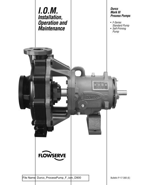
I.O.M.<br />
Installation,<br />
Operation and<br />
Maintenance<br />
Durco<br />
Mark III<br />
Process Pumps<br />
• F-Series<br />
Standard Pump<br />
• Self-Priming<br />
Pump<br />
Bulletin P-17-300 (E)
STANDARD F-SERIES PUMPS<br />
INSTALLATION<br />
Refer to Bulletin P-10-502, Installation, Operation and Maintenance<br />
of Durco Mark III Standard Pumps, Section 4 for installation<br />
instructions for alignment, foundation and motor rotation.<br />
Note: Excessive pump noise or vibration may indicate a<br />
dangerous condition and the pump must be shut down<br />
immediately.<br />
Piping<br />
The general comments on piping contained in Bulletin P-10-502<br />
also apply to the F-Series pump. Due to the non-metallic<br />
construction on the F-Series pump, care must be taken during<br />
installation and operation to avoid pipe forces and moments on<br />
the pump casing in excess of the limits set forth in Table I. See<br />
Figure A for location of forces and moments. The resultant loads<br />
on each nozzle must not exceed the values shown in Table II.<br />
Expansion joints are not required if the piping system will not<br />
impose forces and/or moments in excess of the values listed. A<br />
piping system as shown in Figure B must be used if the piping<br />
system will impose forces and/or moments in excess of the<br />
values shown in Tables I and II.<br />
Table I<br />
Maximum Allowable Combined Forces and Moments<br />
Pump Fx Fy Fz Mx My Mz<br />
1K1.5x1F-6<br />
1K3x1.5F-7<br />
2K3x2F-10<br />
2<br />
63 157 126 316 158 158<br />
(280) (698) (560) (429) (215) (215)<br />
117 293 234 587 293 293<br />
(520) (1303) (1041) (798) (398) (398)<br />
126 316 253 630 316 316<br />
(560) (1406) (1125) (856) (429) (429)<br />
1K3x2FS-7<br />
60<br />
(267)<br />
150<br />
(667)<br />
120<br />
(534)<br />
300<br />
(408)<br />
150<br />
(204)<br />
150<br />
(204)<br />
Note: F in lbs (N) and M in lbf ft (N•m)<br />
Table II<br />
Maximum Allowable Loading For Individual Nozzle<br />
Nozzle Size FR + MR/3 (English) FR + MR*1.09 (Metric)<br />
1 in (25 mm) 120 534<br />
11/2 in (40 mm) 175 779<br />
2 in (50 mm) 231 1028<br />
3 in (80 mm) 350 1557<br />
Note: F in lbs and M in lbf ft are resultants of component forces and<br />
moments on each nozzle. Values for 1K3 x 2FS-7 are half those listed.<br />
Figure A<br />
Location of forces and moments.<br />
Pump Division<br />
Section 1.0<br />
Figure B<br />
Pump installation using expansion joints to prevent<br />
transmission of piping system loads higher than Table I and<br />
Table II to the pump.<br />
Note:<br />
Pipe supports must be<br />
designed to resist the<br />
loads transmitted by<br />
the expansion joint<br />
selected and prevent<br />
them from being<br />
transmitted to pump.<br />
Short spool to accommodate<br />
axial support<br />
Expansion joint<br />
Suction pipe<br />
PREPARATION FOR OPERATION<br />
The preparation for operation of the F-Series pump is the same<br />
as that covered in Bulletin P-10-502 for Durco Mark III<br />
Standard Pumps, Section 4.<br />
OPERATION<br />
The operation of the F-Series pump is the same as that covered<br />
in Bulletin P-10-502 for Durco Mark III Standard Pumps,<br />
Section 4.
MAINTENANCE<br />
Disassembly and Assembly<br />
The method of disassembly and assembly of the F-Series<br />
pump is very similar to the Standard Mark III pump. Refer to<br />
Bulletin P-10-502 for Durco Mark III Standard Pumps, Section<br />
4 and observe the following differences.<br />
Instead of casing studs, the F-Series pump is provided with<br />
through bolts, nuts and washers (#115).<br />
The F-Series pump impeller running clearance is set off the<br />
casing. Attach the power end/rear cover plate assembly to the<br />
casing. Set the impeller clearance by loosening the set screws<br />
(#201A) and rotating the bearing carrier (#201). Turn the<br />
bearing carrier clockwise until the impeller comes into light<br />
rubbing contact with the casing. Rotating the shaft at the same<br />
time will accurately determine this zero setting. Rotate the<br />
bearing carrier counterclockwise to get the proper clearance.<br />
Rotating the bearing carrier the width of one of the indicator<br />
pattern cast into the bearing carrier moves the impeller axially<br />
0.002 in (0.05 mm) (See Figure C).<br />
Figure C<br />
Indicator Pattern<br />
Rotation Equivalent to<br />
0.002 in (0.05 mm) Axial<br />
Movement<br />
Rotate the bearing carrier counterclockwise the required<br />
amount to get the desired clearance to the casing. Tighten the<br />
set screws (#201A) to lock the bearing carrier in place.<br />
Tightening the set screws (#201A) will cause the impeller to<br />
move 0.002 in (0.05 mm) away from the casing because of the<br />
internal looseness in the bearing carrier threads. This must be<br />
considered when setting the impeller clearance.<br />
Pump Division<br />
Section 1.0<br />
The required setting clearance is 0.018 in (0.46 mm) for<br />
speeds of 1750 rpm or less. The setting clearance is 0.021 in<br />
(0.53 mm) for speeds greater than 1750 rpm. A tolerance of<br />
±0.003 in (0.08 mm) is permissible. Add 0.001 in (0.03 mm)<br />
for each 25°F (14°C) increase over 150°F (66°C).<br />
Gaskets<br />
Full face gasketing materials, 1/8 in (3.2 mm) in thickness<br />
having suitable chemical resistance and a Shore durometer<br />
rating of 70, are recommended for the suction and discharge<br />
flanges. Flowserve material engineers will assist in gasket<br />
material selection upon customer request. Flat face mating<br />
flanges are recommended although raised face flanges and/or<br />
ring gaskets may be used if the recommended torque values<br />
for flange bolts and the charted values for maximum pipe loads<br />
are not exceeded.<br />
Bolt Torques<br />
Casing nuts (#115A) should be torqued to 15 lbf ft (20 N-m)<br />
for Group I pumps and 25-30 lbf ft (34-41 N-m) for Group II<br />
pumps. The follower flange (seal gland) nuts (#111A) should<br />
be torqued to 5 lbf ft (7 N-m). The torque required to seal the<br />
casing flanges is 15 lbf ft (20 N-m). This value was established<br />
using rubber gaskets of 70 durometer and standard 150 lb<br />
ANSI drilling.<br />
Machining Impellers<br />
It is possible to machine trim F-Series impellers if smaller<br />
diameter impeller is desired. Care must be taken, however, and<br />
the following procedures are recommended.<br />
1. Maximum recommended machine surface speed is 240<br />
(73 m) to 250 (76 m) feet (meters) per minute.<br />
2. Depth of cut 0.010 to 0.015 in (0.2 to 0.4 mm).<br />
3. Use tungsten carbide tool and change every 1 in (25 mm)<br />
of trim.<br />
4. Reverse feed after each full cut.<br />
3
F-SERIES SELF-PRIMING PUMPS<br />
INSTALLATION<br />
Installation of Durco F-Series self-priming pumps is the same<br />
as for the standard F-Series pumps except that suction pipe<br />
location will be above the pump shaft centerline.<br />
Piping<br />
The comments on piping for the F-Series self-priming pump<br />
are the same as for the standard F-Series pumps.<br />
In addition, the prompt purging of all air from the suction line<br />
of any self-priming pump will be aided by keeping horizontal<br />
runs as short as possible. The horizontal run should also be<br />
sloped down slightly toward the pump for its entire length.<br />
If an external bypass flush is to be used with a single seal, the<br />
piping arrangement shown in Figure D should be used.<br />
PREPARATION FOR OPERATION<br />
Refer to Bulletin P-10-502, Section 4.<br />
In addition, the priming chamber (#146) must be filled with<br />
fluid to at least the shaft centerline for the initial prime.<br />
Thereafter, the proper liquid level will be retained at shutdown<br />
except as noted below under “Operation.” A port (3/4 in NPT)<br />
is provided directly above the suction flange for filling the<br />
priming chamber (#146). All pipe threaded plugs should be<br />
coated with pipe sealant. Several anaerobic pipe sealants are<br />
available including La-Co Slic-tite Paste with Teflon and<br />
Bakerseal Thread Sealing and Lubricating Compound. Teflon<br />
tape should not be used.<br />
OPERATION<br />
The operation of Durco F-Series self-priming pumps is the<br />
same as for standard F-Series pumps. The design of the selfpriming<br />
pump has precluded the need for any check valves to<br />
retain priming liquid. Even without completing the priming<br />
cycle, sufficient liquid will be retained to complete a<br />
subsequent prime. However, repeated incomplete priming<br />
cycles may cause the pump to lose enough liquid back down<br />
the suction line to make priming very slow or impossible without<br />
replenishing. Provisions must be made to vent air from the<br />
pump discharge during the priming cycle.<br />
4<br />
Pump Division<br />
Section 1.0<br />
MAINTENANCE<br />
Disassembly and Assembly<br />
Nearly all maintenance required on a Durco F-Series selfprimer<br />
can be accomplished by removing the power end as in<br />
a standard pump. In the event that it becomes necessary to<br />
separate the casing (#100) and the priming chamber (#146)<br />
this may be done by simply tapping on the casing feet with a<br />
soft mallet after removing all the casing bolts (#115). When<br />
reassembling, a new gasket (#148) will be required between<br />
the priming chamber (#146) and casing (#100), installed the<br />
same as for the standard F-Series pump cover gasket. The<br />
casing (#100) and priming chamber (#146) may be pulled<br />
together with casing bolts (#115) but care should be taken to<br />
pull them together evenly.<br />
Pump maintenance requiring replacement of the impeller<br />
(#103) and/or casing (#100) must assure a 0.06 in (1.6 mm)<br />
to 0.12 in (3.2 mm) clearance between the impeller outside<br />
diameter and casing cutwater.<br />
Gaskets<br />
The comments on gaskets for the F-Series self-priming are the<br />
same as for the standard F-Series pump.<br />
Bolt Torques<br />
Refer to the bolt torque requirements for the standard F-Series<br />
pump. The only difference is that the casing bolts (#115)<br />
should be torqued in at least two stages to a final value of 25-<br />
30 lbf ft (34-41 N•m). The construction of the pump demands<br />
that these values be met and that the torquing be uniform.<br />
Figure D<br />
Recommended external bypass flush arrangement<br />
for single seal on 1K3X2FS-7<br />
Gland flush port located<br />
at 6 o’clock position<br />
Valve or Orifice<br />
Piping must be routed to remain below gland<br />
and to avoid high spots which could trap air.<br />
Tap I<br />
Casing<br />
Drain
GROUP 1 PUMPS<br />
COUPLING GUARD<br />
HHØ<br />
GROUP 2 PUMPS<br />
4" (100) GROUT HOLE LOCATED<br />
UNDER COUPLING<br />
COUPLING GUARD<br />
SELF-PRIMING PUMP<br />
COUPLING GUARD<br />
HHØ<br />
3 1 /2" (89)<br />
HF<br />
HF<br />
171 /2" (445)<br />
SHAFT EXT.<br />
2"<br />
(51)<br />
7 /8" (22) DIA.<br />
3 /16" x 3 /32" KEYWAY<br />
(5 x 2)<br />
HB ± 3 /16" (± 5)<br />
4 1 /2" (114)<br />
23 1 /2" (597)<br />
25 SHAFT EXT. 1<br />
/8"<br />
(67)<br />
1/8" (29) DIA.<br />
1 /4" x 1 /8" KEYWAY<br />
(6 x 3)<br />
HB ± 3 /16" (± 5)<br />
6 1 /4" (159)<br />
HF<br />
4 1 /2" (114)<br />
SHAFT EXT. 7 /8" (22) DIA.<br />
3 /16" x 3 /32" KEYWAY<br />
(5 x 2)<br />
HB ± 3 /16" (± 5)<br />
2"<br />
(51)<br />
22 3 /16" (563)<br />
4 1 /2" (114)<br />
HG<br />
4" (102)<br />
HG<br />
HH<br />
HOLE<br />
DIA.<br />
HG<br />
X<br />
HD ± 1 /4"<br />
(± 6)<br />
1 1 /4" (32)<br />
4" (102)<br />
X<br />
HD ± 0<br />
- 3 /16"<br />
(-5)<br />
1 1 /4" (32)<br />
4" (102)<br />
X<br />
HD ± 1 /4"<br />
(± 6)<br />
1 1 /4" (32)<br />
4 3 /16" (106)<br />
D5 D6<br />
HE HE<br />
HA<br />
D5 D6<br />
HE HE<br />
HA<br />
D5 D6<br />
HE HE<br />
HA<br />
5 1 /4" (134)<br />
8 1 /4" (210)<br />
7 3 /4" (194)<br />
5 /8" (16) DIA.<br />
TYPICAL (3) HOLES<br />
7 1 /4" (184)<br />
5 /8" (16) DIA.<br />
TYPICAL (4) HOLES<br />
3.62 (92)<br />
3.62 (92)<br />
12.50 (318)<br />
5 /8" (16) DIA.<br />
TYPICAL (3) HOLES<br />
7 1 /4" (184)<br />
Pump Division<br />
4 1 /4 (108)<br />
4 1 /4 (108)<br />
Section 1.0<br />
3 (76)<br />
3 (76)<br />
4.87 (124)<br />
4.87 (124)<br />
5
GROUP 1 PUMPS<br />
GROUP 2 PUMPS<br />
SELF-PRIMING PUMP<br />
6<br />
Pump Division<br />
Section 1.0
Standard and Self-Priming F-Series Parts List<br />
ITEM DESCRIPTION<br />
100 CASING<br />
101 PLUG, DRAIN (SELF-PRIMING ONLY)<br />
103 IMPELLER<br />
104 GASKET, IMPELLER<br />
105 SHAFT<br />
106 COVER PLATE<br />
107 GASKET, COVER<br />
108 ADAPTER, BEARING HOUSING (GROUP 2 ONLY)<br />
109 FOOT, BEARING HOUSING<br />
109A SHIM<br />
110 GLAND<br />
111 STUD, GLAND<br />
111A HEXNUT, GLAND<br />
112 SEAL CAGE HALVE<br />
D113 PACKING<br />
114 DEFLECTOR<br />
115 FASTENER, CASING<br />
115A HEXNUT, CASING<br />
115B WASHER<br />
118 OIL SEAL I.B.<br />
119 HOUSING, BEARING<br />
120 BEARING I.B.<br />
121 BEARING O.B.<br />
122 OIL SLINGER (OPTIONAL)<br />
124 LOCKNUT, BEARING<br />
ITEM DESCRIPTION<br />
125 LOCKWASHER, BEARING<br />
129 OIL SEAL O.B.<br />
130 KEY, SHAFT/COUPLING<br />
131 O-RING, BEARING HOUSING (GROUP 2 ONLY)<br />
133 OILER<br />
134 DRAIN - PLUG, HOUSING<br />
135 VENT - PLUG, HOUSING<br />
136 CAP SCREW, FOOT<br />
139 FASTENER, BEARING HOUSING<br />
140 FASTENER, COVER/HOUSING (GROUP 2 ONLY)<br />
146 CHAMBER (SELF-PRIMING ONLY)<br />
148 CHAMBER GASKET (SELF-PRIMING ONLY)<br />
153 SEAL, MECHANICAL<br />
172 NIPPLE, OILER<br />
177 SLEEVE, HOOK TYPE<br />
190 FLANGE, FOLLOWER<br />
190G GASKET, FLANGE<br />
196 PLUG, PRIMING FILL (SELF-PRIMING ONLY)<br />
197 PLUG, SEAL CHAMBER<br />
200 SIGHT GAGE, HOUSING<br />
200A TAG, OIL LEVEL<br />
201 CARRIER, BEARING<br />
201A SET SCREW, CARRIER<br />
201B O-RING, BEARING CARRIER<br />
201C RETAINER RING<br />
Pump Division<br />
Section 1.0<br />
7
F-SERIES PUMP DIMENSIONS & WEIGHTS<br />
SUC.<br />
SIZE<br />
DISC.<br />
SIZE WT. X D D5 D6<br />
SUCTION<br />
SIZE<br />
FLANGE DRILLING<br />
BC<br />
DISCHARGE<br />
SIZE BC<br />
PUMP in in lbs in in in in BOLT in in BOLT in in<br />
(mm) (mm) (kg) (mm) (mm) (mm) (mm) NO. (mm) (mm) NO. (mm) (mm)<br />
1K1.5 x 1F-6 11/2 1 45 61/251/4 51/32 51/32 4<br />
5/8 37/8 4<br />
5/8 31/8 (40) (25) (20) (165) (133) (128) (128) (16) (98) (16) (79)<br />
1K3 x 1.5F-7 3 11/278 61/2 51/4 511/32 511/32 4<br />
3/4 6 4<br />
5/8 37/8 (80) (40) (35) (165) (133) (136) (136) (19) (152) (16) (98)<br />
2K3 x 2F-10 3 2 175 91/2 81/4 811/16 811/16 4<br />
3/4 6 4<br />
3/4 43/4 (80) (50) (79) (241) (210) (221) (221) (19) (152) (19) (119)<br />
1K3 x 2FS-7 3 2 90 71/461/4 63/4 63/4 4<br />
3/4 6 4<br />
3/4 43/4 (80) (50) (41) (184) (159) (171) (171) (19) (152) (19) (119)<br />
F-SERIES PUMPS – GROUP 1<br />
BASEPLATE DIMENSIONS & WEIGHTS (ANSI B73.1M-1991)<br />
MAX. HA HB HD HE HF HG HHØ WT<br />
BASE MOTOR in in in in in in in lbs<br />
FRAME (mm) (mm) (mm) (mm) (mm) (mm) (mm) (kg)<br />
139 184T<br />
148<br />
153<br />
215T<br />
256T<br />
286T<br />
326TS<br />
15 39 9 4 1/2 36 1/2 3 3/4 111<br />
(381) (991) (228) (114) (927) (95) (50)<br />
91/2 18 48 (241) 6 451/2 41/8 3/4 163<br />
(457) (1219) 101/2 (267)<br />
(152) (1156) (105) (19) (74)<br />
117/8 21 53 (302) 71/2 501/2 43/4 212<br />
(533) (1346) 127/8 (327)<br />
(191) (1283) (121) (96)<br />
F-SERIES PUMPS – GROUP 2<br />
BASEPLATE DIMENSIONS & WEIGHTS (ANSI B73.1M-1991)<br />
MAX. HA HB HD HE HF HG HHØ WT<br />
BASE MOTOR in in in in in in in lbs<br />
FRAME (mm) (mm) (mm) (mm) (mm) (mm) (mm) (kg)<br />
245 184T<br />
15 45 12 41/2 421/2 33/4 (381) (1143) (305) (114) (1080) (95) 3/4<br />
129<br />
(59)<br />
252 215T<br />
18 52 123/8 6 491/241/8 (457) (1321) (314) (152) (1257) (105)<br />
(19) 177<br />
(80)<br />
258 286T<br />
21 58 13 551/2 (533) (1473) (330) (1410)<br />
234<br />
(106)<br />
326T<br />
13 71/2 264 22 64<br />
(330) (191)<br />
611/2 328<br />
365T<br />
(559) (1626) 137/8 (1562) 43/4 (352) (121)<br />
1<br />
(25)<br />
(149)<br />
268 405TS<br />
68 147/8 651/2 26<br />
(1727) (378)<br />
9<br />
409<br />
1/2<br />
280 449TS<br />
(660) 80 15<br />
(1664) (186)<br />
7/8 (241) 771/2 (2032) (403) (1969)<br />
481<br />
(218)<br />
USA and Canada<br />
Flowserve Corporation<br />
Pump Division<br />
Millennium Center<br />
222 Las Colinas Blvd., 15th Floor<br />
Irving, TX 75039-5421 USA<br />
Telephone: 1 972 443 6500<br />
Telefax: 1 972 443 6800<br />
Europe, Africa, Middle East<br />
Flowserve Ltd.<br />
Pump Division<br />
Harley House<br />
94 Hare Lane, Claygate, Esher<br />
Surrey KT10 ORB, UK<br />
Telephone: 44 1372 463700<br />
Telefax: 44 1372 463801<br />
Printed in U.S.A.<br />
September 2000<br />
© Flowserve Corporation<br />
Your local Flowserve representative:<br />
F-SERIES SELF-PRIMING PUMPS – GROUP 1<br />
BASEPLATE DIMENSIONS & WEIGHTS (ANSI B73.1M-1991)<br />
MAX. HA HB HD HE HF HG HHØ WT<br />
BASE MOTOR in in in in in in in lbs<br />
FRAME (mm) (mm) (mm) (mm) (mm) (mm) (mm) (kg)<br />
139 184T<br />
148<br />
153<br />
215T<br />
256T<br />
286T<br />
326TS<br />
Flowserve has numerous manufacturing, sales,<br />
and service operations throughout the world.<br />
Please contact one of the regional centers to<br />
determine the location of the nearest office.<br />
Pump Division<br />
Section 1.0<br />
15 39 9 4 1/2 36 1/2 3 3/4 111<br />
(381) (991) (228) (114) (927) (95) (50)<br />
91/2 18 48 (241) 6 451/2 41/8 3/4 163<br />
(457) (1219) 101/2 (267)<br />
(152) (1156) (105) (19) (74)<br />
117/8 21 53 (302) 71/2 501/2 43/4 212<br />
(533) (1346) 127/8 (327)<br />
(191) (1283) (121) (96)<br />
Latin America<br />
Flowserve de Venezuela S.A.<br />
Pump Division<br />
Torre Ejecutiva No. 75-51<br />
Ave. 4 Bella Vista entre calles 75 y 76<br />
1 er Piso Ofic. 1B, Maracaibo<br />
Edo. Zulia 4002-010. Venezuela<br />
Telephone: 58 61 932 767<br />
Telefax: 58 61 933 114<br />
Asia Pacific<br />
Flowserve Pte. Ltd.<br />
Pump Division<br />
12 Tuas Avenue 20<br />
Singapore 638824<br />
Republic of Singapore<br />
Telephone: 65 862 3332<br />
Telefax: 65 868 4603


