Manual for American Audio VLP-1500 Power Amplifier
Manual for American Audio VLP-1500 Power Amplifier
Manual for American Audio VLP-1500 Power Amplifier

You also want an ePaper? Increase the reach of your titles
YUMPU automatically turns print PDFs into web optimized ePapers that Google loves.
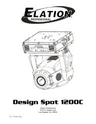
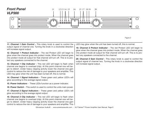
Front Panel<br />
<strong>VLP</strong>300<br />
10<br />
6<br />
PROFESSIONAL POWER AMPLIFIER<br />
15 PRO CLIP 10 15 POWER<br />
POWER 15 10 CLIP PRO<br />
11. Channel 1 Gain Control - This rotary knob is used to control the<br />
output signal of channel one. Turning the knob in a clockwise direction<br />
will increase signal output.<br />
12. Channel 1 Protect Indicator - The red Protect LED will begin to<br />
glow when the channel goes into protect mode. When the channel goes<br />
into protect mode all output <strong>for</strong> that channel will turn off. This is to protect<br />
any speakers connected to the channel.<br />
13. Channel 1 Clip Indicator - This red LED will begin to flash when<br />
channel one begins to overload (clip). At this point channel one will begin<br />
to distort. Under heavy clipping activity lower the channel one gain<br />
control to reduce the risk of damage to your speakers and amplifier. This<br />
LED may glow when the unit has been turned off, this is normal.<br />
14. Channel 1 Signal Indicators - These green and yellow LED’s will<br />
glow according to the average signal output.<br />
15. <strong>Power</strong> Indicators - These LEDs function as a power indicator.<br />
16. <strong>Power</strong> Switch - This switch is used to control the units main power.<br />
17. Channel 2 Signal Indicators - These green and yellow LED’s will<br />
glow according to the average signal output.<br />
30<br />
80<br />
11 12 13 14 15 16 15 17 18 19 20<br />
0 dB<br />
3<br />
1<br />
CH A<br />
<strong>VLP</strong>300<br />
18. Channel 2 Clip Indicator - This red LED will begin to flash when<br />
channel one begins to overload (clip). At this point channel one will begin<br />
to distort. Under heavy clipping activity lower the channel one gain<br />
control to reduce the risk of damage to your speakers and amplifier. This<br />
©<strong>American</strong> <strong>Audio</strong>® - www.americanaudio.com - <strong>VLP</strong> Series <strong>Power</strong> <strong>Amplifier</strong> User <strong>Manual</strong> Page 6<br />
30<br />
CH B<br />
15<br />
10<br />
80<br />
6<br />
0 dB<br />
3<br />
1<br />
Figure 2<br />
LED may glow when the unit has been turned off, this is normal.<br />
19. Channel 2 Protect Indicator - The red Protect LED will begin to<br />
glow when the channel goes into protect mode. When the channel goes<br />
into protect mode all output <strong>for</strong> that channel will turn off. This is to protect<br />
any speakers connected to the channel.<br />
20. Channel 2 Gain Control - This rotary knob is used to control the<br />
output signal of channel two. Turning the knob in a clockwise direction<br />
will increase signal output.