High-Cost CFD on a Low-Cost Cluster - The Aggregate
High-Cost CFD on a Low-Cost Cluster - The Aggregate
High-Cost CFD on a Low-Cost Cluster - The Aggregate

You also want an ePaper? Increase the reach of your titles
YUMPU automatically turns print PDFs into web optimized ePapers that Google loves.
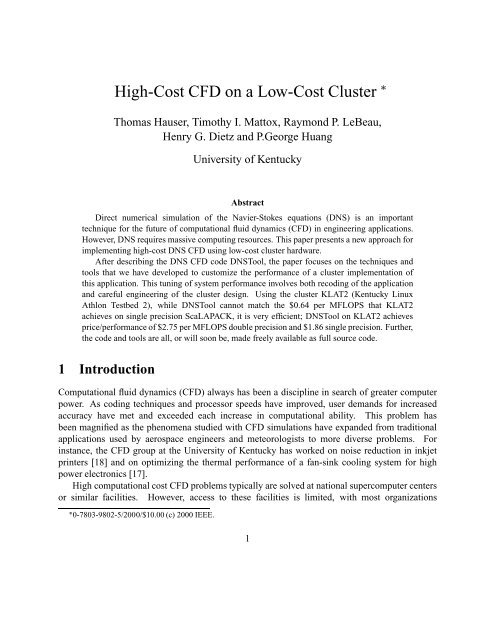
<str<strong>on</strong>g>High</str<strong>on</strong>g>-<str<strong>on</strong>g>Cost</str<strong>on</strong>g> <str<strong>on</strong>g>CFD</str<strong>on</strong>g> <strong>on</strong> a <strong>Low</strong>-<str<strong>on</strong>g>Cost</str<strong>on</strong>g> <strong>Cluster</strong><br />
Thomas Hauser, Timothy I. Mattox, Raym<strong>on</strong>d P. LeBeau,<br />
Henry G. Dietz and P.George Huang<br />
University of Kentucky<br />
Abstract<br />
Direct numerical simulati<strong>on</strong> of the Navier-Stokes equati<strong>on</strong>s (DNS) is an important<br />
technique for the future of computati<strong>on</strong>al fluid dynamics (<str<strong>on</strong>g>CFD</str<strong>on</strong>g>) in engineering applicati<strong>on</strong>s.<br />
However, DNS requires massive computing resources. This paper presents a new approach for<br />
implementing high-cost DNS <str<strong>on</strong>g>CFD</str<strong>on</strong>g> using low-cost cluster hardware.<br />
After describing the DNS <str<strong>on</strong>g>CFD</str<strong>on</strong>g> code DNSTool, the paper focuses <strong>on</strong> the techniques and<br />
tools that we have developed to customize the performance of a cluster implementati<strong>on</strong> of<br />
this applicati<strong>on</strong>. This tuning of system performance involves both recoding of the applicati<strong>on</strong><br />
and careful engineering of the cluster design. Using the cluster KLAT2 (Kentucky Linux<br />
Athl<strong>on</strong> Testbed 2), while DNSTool cannot match the $0.64 per MFLOPS that KLAT2<br />
achieves <strong>on</strong> single precisi<strong>on</strong> ScaLAPACK, it is very efficient; DNSTool <strong>on</strong> KLAT2 achieves<br />
price/performance of $2.75 per MFLOPS double precisi<strong>on</strong> and $1.86 single precisi<strong>on</strong>. Further,<br />
the code and tools are all, or will so<strong>on</strong> be, made freely available as full source code.<br />
1 Introducti<strong>on</strong><br />
Computati<strong>on</strong>al fluid dynamics (<str<strong>on</strong>g>CFD</str<strong>on</strong>g>) always has been a discipline in search of greater computer<br />
power. As coding techniques and processor speeds have improved, user demands for increased<br />
accuracy have met and exceeded each increase in computati<strong>on</strong>al ability. This problem has<br />
been magnified as the phenomena studied with <str<strong>on</strong>g>CFD</str<strong>on</strong>g> simulati<strong>on</strong>s have expanded from traditi<strong>on</strong>al<br />
applicati<strong>on</strong>s used by aerospace engineers and meteorologists to more diverse problems. For<br />
instance, the <str<strong>on</strong>g>CFD</str<strong>on</strong>g> group at the University of Kentucky has worked <strong>on</strong> noise reducti<strong>on</strong> in inkjet<br />
printers [18] and <strong>on</strong> optimizing the thermal performance of a fan-sink cooling system for high<br />
power electr<strong>on</strong>ics [17].<br />
<str<strong>on</strong>g>High</str<strong>on</strong>g> computati<strong>on</strong>al cost <str<strong>on</strong>g>CFD</str<strong>on</strong>g> problems typically are solved at nati<strong>on</strong>al supercomputer centers<br />
or similar facilities. However, access to these facilities is limited, with most organizati<strong>on</strong>s<br />
¡ 0-7803-9802-5/2000/$10.00 (c) 2000 IEEE.<br />
1
outside of government and academia having no access at all. Alternately, large corporati<strong>on</strong>s<br />
and universities can purchase shared-memory supercomputers such as those built by SGI and<br />
HP; however, these machines are expensive, with unclear upgrade paths and relatively high<br />
maintenance costs. Smaller companies and research instituti<strong>on</strong>s simply cannot afford these<br />
systems. Thus, the very high up-fr<strong>on</strong>t cost of <str<strong>on</strong>g>CFD</str<strong>on</strong>g> analysis has placed the technology bey<strong>on</strong>d<br />
the reach of many of the researchers and engineers whose applicati<strong>on</strong>s could benefit the most from<br />
the new abilities of <str<strong>on</strong>g>CFD</str<strong>on</strong>g> codes.<br />
This paper presents an alternative approach to the computati<strong>on</strong>al challenges of advanced <str<strong>on</strong>g>CFD</str<strong>on</strong>g><br />
problems: use inexpensive, high-performance, clusters of PCs – "Beowulfs."[1] Over the past few<br />
years, many very positive claims have been made in favor of PC clusters, and the hype usually<br />
gives better performance than the actual systems do. However, by carefully engineering the<br />
cluster design, using (and building) tools to improve applicati<strong>on</strong> performance, and restructuring<br />
the applicati<strong>on</strong> code for the cluster, it is possible to realize most of the benefits that are so often<br />
claimed for clusters.<br />
Since February 1994, when we built the first parallel-processing Linux PC cluster, we have<br />
been very aggressively pursuing any hardware and software system technologies that can improve<br />
the performance or give new capabilities to cluster supercomputers. DNSTool requires a good<br />
network with high bisecti<strong>on</strong> bandwidth; we developed a new class of network architectures, and<br />
design tools for them, that make it possible to build an appropriate network at minimal cost.<br />
DNSTool also requires lots of memory bandwidth and fast floating point math; we provide these by<br />
using uniprocessor Athl<strong>on</strong> PCs and tools to accelerate floating point performance using 3DNow!.<br />
Our cluster, KLAT2 (Kentucky Linux Athl<strong>on</strong> Testbed 2), was not designed to <strong>on</strong>ly run DNSTool,<br />
but it was designed to run applicati<strong>on</strong>s like DNSTool excepti<strong>on</strong>ally well.<br />
KLAT2 (figure 1) is a cluster of 64 (plus 2 "hot spare") 700MHz AMD Athl<strong>on</strong> PCs. Each PC<br />
c<strong>on</strong>tains 128MB of main memory and four 100Mb/s Fast Ethernet interfaces. Nine (and <strong>on</strong>e spare)<br />
32-way Ethernet switches are used in an unusual network architecture to interc<strong>on</strong>nect the machines<br />
with low latency and high bandwidth.<br />
Of course, it was necessary to restructure DNSTool to run more efficiently <strong>on</strong> KLAT2. Many of<br />
the changes were generic and would improve the code performance <strong>on</strong> any cache-based machine.<br />
Some of the changes reduced the total FLOPs needed for the computati<strong>on</strong>s, reducing total time<br />
somewhat by replacing floating point recomputati<strong>on</strong>s with more awkward reference patterns – not<br />
really what we should have d<strong>on</strong>e if achieving the "peak MFLOPS rate" was our goal. Still other<br />
changes were highly specific to the features of KLAT2, such as use of Athl<strong>on</strong> 3DNow! support.<br />
<strong>The</strong> changes were not easy, but applying them to other <str<strong>on</strong>g>CFD</str<strong>on</strong>g> codes will now be less difficult.<br />
<strong>The</strong> combinati<strong>on</strong> of DNSTool and KLAT2 yields excepti<strong>on</strong>ally good price/performance: $2.75<br />
per MFLOPS double-precisi<strong>on</strong> 80/64-bit operati<strong>on</strong>s and $1.86 per MFLOPS using single-precisi<strong>on</strong><br />
3DNow!. Maintenance is made relatively painless by including spares in the initial system (and<br />
we have included these "unnecessary" spare parts in the system cost). Upgrading the system can<br />
be d<strong>on</strong>e incrementally by our tools to design an improved network, replacing the processors with<br />
a later (faster) versi<strong>on</strong>, etc. Further, although we have not experimented with clusters larger than<br />
2
Figure 1: Kentucky Linux Athl<strong>on</strong> Testbed 2 (KLAT2)<br />
KLAT2, given larger <str<strong>on</strong>g>CFD</str<strong>on</strong>g> problems, there is nothing about the design of KLAT2 or DNSTool that<br />
would prevent efficiently scaling the system to many more processors.<br />
Thus, the design tools and implementati<strong>on</strong> of KLAT2 and DNSTool represent a significant step<br />
toward moving complex <str<strong>on</strong>g>CFD</str<strong>on</strong>g> simulati<strong>on</strong>s from the supercomputer center to the center of your lab.<br />
<strong>The</strong> next secti<strong>on</strong> of this paper describes the equati<strong>on</strong>s that govern DNSTool’s <str<strong>on</strong>g>CFD</str<strong>on</strong>g> simulati<strong>on</strong>.<br />
Secti<strong>on</strong> 3 describes KLAT2 and, more importantly, the tools that we have created to optimize<br />
the system design and to help code use the system more efficiently. In secti<strong>on</strong> 4, we detail how<br />
DNSTool was restructured and how we used our tools to tune the code for KLAT2. Secti<strong>on</strong> 5<br />
presents both the <str<strong>on</strong>g>CFD</str<strong>on</strong>g> output and computati<strong>on</strong>al performance obtained from applying DNSTool<br />
to a real engineering problem: flow over a single turbine blade. <strong>The</strong> complete parts list and<br />
itemized cost of KLAT2 also is given in secti<strong>on</strong> 5. <strong>The</strong> final secti<strong>on</strong> of the paper summarizes<br />
the c<strong>on</strong>tributi<strong>on</strong>s and suggests directi<strong>on</strong>s for future research.<br />
2 <strong>The</strong> <str<strong>on</strong>g>CFD</str<strong>on</strong>g> Algorithm<br />
In theory, almost all fluid dynamics problems can be solved by the direct applicati<strong>on</strong> of the Navier-<br />
Stokes equati<strong>on</strong>s to a sufficiently fine grid. Direct numerical simulati<strong>on</strong> of the Navier-Stokes<br />
equati<strong>on</strong>s (DNS) provides a useful tool for understanding the complex physics in engineering<br />
processes. Even though with current computer technology, DNS can <strong>on</strong>ly be applied to simplified<br />
problems, DNS is likely to become the standard practice for engineering simulati<strong>on</strong>s in the<br />
3
21st century. <strong>The</strong> challenges in applying DNS to practical engineering problems involve: (1)<br />
more accurate numerical soluti<strong>on</strong>s, (2) high demands <strong>on</strong> computer memory, and (3) greater<br />
computati<strong>on</strong>al speed. Traditi<strong>on</strong>ally, the focus of <str<strong>on</strong>g>CFD</str<strong>on</strong>g> research was <strong>on</strong> improving the numerical<br />
accuracy of the soluti<strong>on</strong> through more complicated modeling of the physical phenomena.<br />
C<strong>on</strong>tinual advances in computer architecture and technology have opened the door for focusing <strong>on</strong><br />
the latter two areas. Meeting the latter two challenges will allow the applicati<strong>on</strong> of DNS directly<br />
to practical engineering problems.<br />
2.1 <strong>The</strong> Governing Equati<strong>on</strong>s for DNS<br />
Direct numerical simulati<strong>on</strong> is based <strong>on</strong> solving the full, time-dependent Navier-Stokes Equati<strong>on</strong>s<br />
for an ideal gas which express the c<strong>on</strong>servati<strong>on</strong> of mass, momentum, and energy for a compressible<br />
Newt<strong>on</strong>ian fluid. <strong>The</strong> equati<strong>on</strong>s written in curvilinear coordinates are<br />
¢¤£<br />
¢¦¥¨§<br />
¢¤©<br />
¢¦§<br />
¢¤©<br />
¢¤§<br />
¢¤©<br />
¢¤<br />
¢¤<br />
¢§<br />
¢¤<br />
¢§<br />
¢¤<br />
(1)<br />
¢¤<br />
where £<br />
is the vector of the c<strong>on</strong>servative variables multiplied by the volume of the computati<strong>on</strong>al<br />
cell, , and is defined by<br />
<strong>The</strong> ©<br />
’s and <br />
and <br />
represent the directi<strong>on</strong>s of the fluxes. <strong>The</strong> inviscid fluxes are given by<br />
£<br />
(2)<br />
<br />
’s denote the c<strong>on</strong>vective and viscous fluxes, respectively, and the subscripts , <br />
©<br />
©<br />
©<br />
<br />
<br />
<br />
<br />
<br />
<br />
<br />
<br />
<br />
<br />
<br />
<br />
<br />
<br />
<br />
<br />
¦<br />
<br />
<br />
<br />
§ <br />
<br />
<br />
<br />
§<br />
<br />
§<br />
<br />
§<br />
<br />
<br />
<br />
§ <br />
<br />
¦<br />
<br />
<br />
<br />
§ <br />
<br />
<br />
§<br />
§<br />
<br />
§<br />
<br />
§<br />
<br />
§<br />
<br />
§<br />
4<br />
<br />
<br />
<br />
¢¦¢<br />
¢¦¢<br />
¢¦¢¤<br />
¢¦¢¦¥<br />
<br />
¢¦¢¦<br />
¢¦¢¤<br />
¢¤¢¤<br />
¢¢¦¥<br />
<br />
¢¤¢¦<br />
¢¤¢<br />
¢¤¢¤<br />
¢¢¦¥<br />
<br />
<br />
<br />
<br />
<br />
<br />
<br />
<br />
<br />
<br />
<br />
<br />
<br />
<br />
(3)<br />
(4)<br />
(5)
where is the density, is the pressure, , , are the cartesian velocity <br />
comp<strong>on</strong>ents,<br />
is the total energy per unit volume and equal to the sum of the internal energy, , and the kinetic<br />
energy, , and the ’s are the c<strong>on</strong>travariant velocity comp<strong>on</strong>ents defined by<br />
where<br />
¦ <br />
¦<br />
<br />
<br />
<br />
¦<br />
<br />
¦<br />
¦<br />
<br />
<br />
<br />
¦<br />
¤<br />
<br />
¤<br />
¤ ¤<br />
¤ ¤<br />
¤<br />
¦ ¦ <br />
<strong>The</strong> viscous fluxes in the , and directi<strong>on</strong>s are given by<br />
<br />
<br />
<br />
<br />
<br />
<br />
<br />
<br />
<br />
<br />
<br />
<br />
<br />
<br />
<br />
<br />
<br />
<br />
<br />
<br />
<br />
¦<br />
<br />
<br />
<br />
¦<br />
¦<br />
<br />
¦ <br />
¦<br />
<br />
<br />
<br />
<br />
<br />
<br />
¦<br />
<br />
<br />
¦<br />
¦<br />
<br />
<br />
<br />
<br />
<br />
<br />
<br />
¦<br />
<br />
¦<br />
<br />
<br />
<br />
<br />
¤<br />
¦<br />
<br />
¦ <br />
<br />
<br />
<br />
<br />
¦<br />
<br />
¤<br />
<br />
¦ <br />
<br />
<br />
¤<br />
¤<br />
<br />
<br />
¦<br />
¦<br />
<br />
¦ <br />
¤<br />
¤<br />
¦<br />
<br />
<br />
<br />
<br />
<br />
<br />
¤<br />
<br />
¤<br />
<br />
<br />
<br />
¤<br />
<br />
<br />
<br />
<br />
¤<br />
<br />
<br />
¤<br />
<br />
¤ <br />
<br />
<br />
<br />
<br />
<br />
<br />
<br />
<br />
<br />
<br />
<br />
<br />
<br />
(6)<br />
<br />
¦<br />
<br />
<br />
<br />
<br />
¤<br />
¦<br />
<br />
¤ ¦<br />
<br />
<br />
¤<br />
¤<br />
¤<br />
<br />
<br />
<br />
¤<br />
<br />
¤ <br />
¤<br />
<br />
¤<br />
¤<br />
¤<br />
<br />
<br />
¤<br />
<br />
<br />
¤ <br />
¤<br />
¤<br />
<br />
<br />
<br />
<br />
<br />
<br />
<br />
<br />
<br />
<br />
<br />
<br />
(7)<br />
(8)<br />
(9)<br />
<br />
<br />
(10)<br />
<br />
<br />
<br />
<br />
<strong>The</strong> stress tensor and the heat flux vector are defined by<br />
5
¤ <br />
<br />
¤ <br />
<br />
¤ <br />
¤<br />
<br />
<br />
<br />
¤<br />
<br />
¤<br />
and <br />
<br />
<br />
<br />
<br />
<br />
<br />
¤ <br />
<br />
<br />
¤ <br />
<br />
<br />
¤ <br />
<br />
¦<br />
<br />
¦<br />
<br />
¤<br />
<br />
<br />
¦<br />
¦<br />
<br />
<br />
<br />
<br />
<br />
<br />
<br />
¤<br />
<br />
¤<br />
<br />
¤<br />
where and are molecular viscosity and thermal c<strong>on</strong>ductivity, respectively.<br />
<strong>The</strong> pressure is related to the density and temperature, , according to the equati<strong>on</strong> of state<br />
<br />
<br />
where is the ratio of the specific heats. <strong>The</strong> coefficient of viscosity, , and thermal c<strong>on</strong>ductivity,<br />
<br />
, are related by the c<strong>on</strong>stant Prandl number .<br />
2.2 Numerical Algorithms<br />
<br />
<br />
<strong>The</strong>re are wide variety of <str<strong>on</strong>g>CFD</str<strong>on</strong>g> techniques that can solve these governing equati<strong>on</strong>s. Of the several<br />
<str<strong>on</strong>g>CFD</str<strong>on</strong>g> codes employed or under development at the University of Kentucky, we have chosen to use<br />
DNSTool [9], a code package originating at the University of Technology Munich and undergoing<br />
further development at the University of Kentucky. DNSTool is specifically designed to solve<br />
<br />
<br />
6<br />
<br />
<br />
¦<br />
<br />
¦<br />
¤<br />
(11)<br />
(12)<br />
(13)<br />
(14)<br />
(15)<br />
(16)<br />
(17)<br />
(18)<br />
(19)<br />
(20)<br />
(21)
three-dimensi<strong>on</strong>al flow problems using the direct numerical simulati<strong>on</strong> model for turbulence. It has<br />
primarily been used to simulate hypers<strong>on</strong>ic flow around blunt objects [10], but is readily applicable<br />
to a wide range of engineering <str<strong>on</strong>g>CFD</str<strong>on</strong>g> problems. <strong>The</strong> choice of this particular code is based <strong>on</strong><br />
it being MPI-ready, having been tested <strong>on</strong> numerous multiprocessor platforms, and <strong>on</strong> its clean<br />
program organizati<strong>on</strong>, making it readily accessible to code-performance enhancements.<br />
<strong>The</strong> base DNSTool code is over 20000 lines of C, broken into more than 100 separate files.<br />
Briefly, DNSTool solves the governing equati<strong>on</strong>s as follows. <strong>The</strong> flux vector, representing the<br />
advective and dissipati<strong>on</strong> flux terms of the Navier-Stokes equati<strong>on</strong>s, are solved with the AUSM<br />
flux-splitting scheme [14]<br />
<br />
<br />
<br />
<br />
<br />
<br />
<br />
<br />
<br />
<br />
<br />
<br />
<br />
<br />
<br />
<br />
<br />
<br />
<br />
<br />
<br />
<br />
<br />
<br />
<br />
<br />
<br />
<br />
<br />
<br />
<br />
<br />
<br />
<br />
<br />
<br />
<br />
<br />
<br />
<br />
<br />
<br />
<br />
<br />
<br />
<br />
<br />
<br />
<br />
<br />
<br />
<br />
where the geometrical quantities to account for the curvilinear coordinates are c<strong>on</strong>tained in<br />
<br />
<br />
<br />
<br />
<br />
<br />
<br />
<br />
<br />
<br />
<br />
<br />
<br />
<br />
<br />
<br />
<br />
<br />
<br />
<br />
<br />
<br />
<br />
<br />
<br />
<br />
¤<br />
<br />
<br />
<br />
and . <strong>The</strong> L subscript corresp<strong>on</strong>ds to <br />
the values extrapolated from the left volume center<br />
to the face, the R subscript to those extrapolated from the right volume center <br />
to the face.<br />
A key feature of the AUSM technique, which was <br />
designed to handle high Mach<br />
<br />
number <br />
flows,<br />
<br />
is the <br />
<br />
replacement of the normal velocity through the face, , or the Mach<br />
is evaluated as follows<br />
<br />
number multiplied by the speed of sound. <strong>The</strong> term <br />
where the superscripts and ¢ indicate<br />
<br />
<br />
<br />
<br />
Likewise, the pressure is evaluated as per Liou [13]<br />
¤ £<br />
¥<br />
¤ £<br />
¥<br />
¦ ¤<br />
¦ ¤<br />
¨<br />
<br />
<br />
¨ <br />
<br />
<br />
<br />
<br />
<br />
<br />
<br />
<br />
¡<br />
<br />
§<br />
<br />
© <br />
<br />
§<br />
<br />
<br />
<br />
<br />
©<br />
<br />
<br />
<br />
7<br />
<br />
<br />
<br />
<br />
<br />
<br />
<br />
<br />
<br />
<br />
<br />
<br />
<br />
<br />
, with <br />
<br />
(22)<br />
(23)<br />
<br />
<br />
<br />
<br />
(24)<br />
(25)
¡ <br />
<br />
<br />
<br />
<br />
<strong>The</strong> dissipati<strong>on</strong> term evaluati<strong>on</strong> is also M-dependent, although the c<strong>on</strong>struct is somewhat<br />
different: <br />
with the VL term found from<br />
<br />
<br />
<br />
<br />
<br />
<br />
<br />
<br />
<br />
<br />
<br />
<br />
<br />
<br />
<br />
<br />
<br />
<br />
<br />
<br />
<br />
and the AUSM dissipati<strong>on</strong> term from<br />
<br />
<br />
<br />
<br />
<br />
<br />
<br />
<br />
<br />
<br />
<br />
<br />
<br />
<br />
<br />
<br />
<br />
<br />
(26)<br />
(27)<br />
<br />
<br />
<br />
¡ <br />
<br />
<br />
<br />
¡ <br />
<br />
<br />
<br />
<br />
<br />
<br />
<br />
<br />
<br />
<br />
<br />
<br />
<br />
<br />
<br />
<br />
<br />
<br />
<strong>The</strong> values of <br />
<br />
<br />
<br />
<br />
<br />
<br />
<br />
<br />
<br />
are a functi<strong>on</strong> of the pressure distributi<strong>on</strong>, while the value of is a functi<strong>on</strong> of the<br />
eigenvalues, .<br />
<strong>The</strong> left and right extrapolated values of the c<strong>on</strong>servative variables are determined by a thirdorder<br />
MUSCL-type extrapolati<strong>on</strong>, in which any given quantity or is defined by<br />
where<br />
<br />
<br />
<br />
<br />
<br />
<br />
<br />
<br />
<br />
<br />
<br />
<br />
<br />
<br />
<br />
<br />
<br />
<br />
<br />
<br />
<br />
<br />
<br />
<br />
<br />
<br />
<br />
<br />
<br />
<br />
<br />
<br />
<br />
<br />
<br />
<br />
<br />
<br />
<strong>The</strong> diffusive flux gradients are evaluated using a variati<strong>on</strong> of the circulati<strong>on</strong> method<br />
<br />
<br />
<br />
<br />
8<br />
<br />
<br />
<br />
<br />
<br />
<br />
<br />
(28)<br />
(29)<br />
(30)<br />
(31)<br />
(32)
or in terms of the finite volume grid<br />
<br />
<br />
<br />
<br />
<br />
<br />
<br />
<br />
<br />
<br />
<br />
<br />
<br />
<br />
<br />
<br />
<br />
<br />
<br />
<br />
<br />
<br />
<br />
<br />
<br />
<br />
<br />
<br />
<br />
<br />
<br />
<br />
<br />
<br />
<br />
<br />
<br />
<br />
<br />
<br />
<br />
<br />
<br />
<br />
<strong>The</strong>se spatial calculati<strong>on</strong>s are performed in a series of three sweeps in the i-, j-, and k-directi<strong>on</strong>s.<br />
This trio of sweeps are made each sub-iterati<strong>on</strong> of the multi-step time integrati<strong>on</strong>, leading to<br />
as many as 12 sweeps in the case of the 4th-order Runge-Kutta method. Both the 2nd-order<br />
(for unsteady soluti<strong>on</strong>s) and 4th-order (for steady soluti<strong>on</strong>s) Runge-Kutta methods were used by<br />
DNSTool/KLAT2 machine.<br />
2.3 Parallelizati<strong>on</strong><br />
<br />
<br />
<br />
<br />
<strong>The</strong> parallel structure of DNSTool is based <strong>on</strong> splitting the computati<strong>on</strong>al grid into sub-blocks,<br />
which are then distributed to each processor (figure 2). For a complex geometry, this is a n<strong>on</strong>trivial<br />
exercise where an uneven load-balance across different processors could significantly reduce the<br />
computati<strong>on</strong>al efficiency of the overall code. <strong>The</strong> partiti<strong>on</strong>ing of the grid into sub-blocks is<br />
performed independently of the grid generati<strong>on</strong>, using virtual partiti<strong>on</strong>s to define the domains<br />
corresp<strong>on</strong>ding to each processor. <strong>The</strong> current algorithm governing the partiti<strong>on</strong> process is based<br />
<strong>on</strong> spectral recursive bisecti<strong>on</strong> in c<strong>on</strong>juncti<strong>on</strong> with a small database of the computati<strong>on</strong>al speeds<br />
associated with each node. <strong>The</strong> splitting is performed as a preprocessing task, generating a file that<br />
maps the grid sub-blocks <strong>on</strong>to the processors. This file is the <strong>on</strong>ly difference between performing<br />
a serial computati<strong>on</strong> and a parallel computati<strong>on</strong> with DNSTool.<br />
Communicati<strong>on</strong>s between the grid sub-blocks occurs when the sub-blocks exchange data about<br />
the flow variables at the boundaries. As show in figure 2, the flow variables <strong>on</strong> the edge of<br />
<strong>on</strong>e grid block are communicated to the dummy points of the neighboring grid block, and vice<br />
versa. DNSTool requires such a communicati<strong>on</strong> step after each update, or subiterati<strong>on</strong>, of the<br />
flow variables. <strong>The</strong> low-level implementati<strong>on</strong> of the communicati<strong>on</strong> between the sub-blocks uses<br />
a MPI-based communicati<strong>on</strong>s system. <strong>The</strong> communicati<strong>on</strong> model is a mailbox algorithm where<br />
the data is sent in a n<strong>on</strong>-blocking communicati<strong>on</strong> mode as early as possible.<br />
<strong>The</strong> overall parallel framework of DNSTool is managed by MBLIB, a code library that<br />
efficiently c<strong>on</strong>trols the domain decompositi<strong>on</strong> and associated communicati<strong>on</strong> patterns. On top of<br />
this library the efficient compressible Navier-Stokes solver described previously is implemented.<br />
Thanks to MBLIB, the Navier-Stokes solver is isolated from the parallel decompositi<strong>on</strong>-the solver<br />
code is the same whether the overall computati<strong>on</strong> is performed <strong>on</strong> a single domain or any number<br />
of subdomains.<br />
9<br />
<br />
<br />
<br />
<br />
(33)
dummy points<br />
data exchange<br />
Grid block<br />
data exchange<br />
data exchange<br />
virtual block <br />
boundaries<br />
Figure 2: Communicati<strong>on</strong> pattern of DNSTool<br />
3 Engineering a <strong>Cluster</strong> Supercomputer<br />
Since February 1994, when we built the first parallel-processing Linux PC cluster [4], we have been<br />
very aggressively pursuing any hardware and software system technologies that can improve the<br />
performance or give new capabilities to cluster supercomputers. As the latest in a l<strong>on</strong>g sequence of<br />
clusters that we have built, KLAT2 c<strong>on</strong>tinues our traditi<strong>on</strong> of using innovative new technologies.<br />
However, unlike all our previous systems, KLAT2’s base c<strong>on</strong>figurati<strong>on</strong> uses no custom hardware<br />
- all of the performance improvements are accomplished by changing the way in which standard<br />
hardware comp<strong>on</strong>ents are c<strong>on</strong>figured and/or restructuring the software to take better advantage of<br />
the hardware.<br />
Without using custom hardware, there are three key approaches that we can use to improve the<br />
performance of a <str<strong>on</strong>g>CFD</str<strong>on</strong>g> code <strong>on</strong> KLAT2:<br />
1. Optimizati<strong>on</strong> and general restructuring of the <str<strong>on</strong>g>CFD</str<strong>on</strong>g> code to improve performance. Many<br />
of these optimizati<strong>on</strong>s are not really specific to KLAT2, but improve performance <strong>on</strong><br />
most computers. We have performed many such optimizati<strong>on</strong>s, most of which involve<br />
restructuring to change the memory reference behavior and to reorder the calculati<strong>on</strong>s so that<br />
more redundant computati<strong>on</strong>s can be eliminated. Our goal has been to minimize executi<strong>on</strong><br />
time despite the fact that some of the optimizati<strong>on</strong>s also reduce the achieved FLOPs rate.<br />
2. Tailoring of the network hardware structure and communicati<strong>on</strong> patterns to optimize network<br />
performance. <strong>The</strong> new techniques we used to design KLAT2’s network allow us to optimize<br />
10<br />
data exchange
network performance in general or even to specialize KLAT2’s network for this <str<strong>on</strong>g>CFD</str<strong>on</strong>g> code.<br />
All runs reported here were performed with a generalized network rather than <strong>on</strong>e specialized<br />
for this code.<br />
3. Use of the Athl<strong>on</strong>’s 3DNow! vector floating point instructi<strong>on</strong>s. Unfortunately, these<br />
instructi<strong>on</strong>s <strong>on</strong>ly support 32-bit precisi<strong>on</strong> for floating point arithmetic and also have various<br />
performance issues that make them difficult to use. However, we have developed compiler<br />
technology and other support that makes use of 3DNow! feasible. This is <strong>on</strong>e of the key<br />
reas<strong>on</strong>s that KLAT2 uses AMD Athl<strong>on</strong> processors.<br />
Achieving high performance from this <str<strong>on</strong>g>CFD</str<strong>on</strong>g> code requires the first two approaches. <strong>The</strong> third<br />
approach, use of 3DNow!, we viewed with skepticism until we were able to verify that 3DNow!<br />
single-precisi<strong>on</strong> floating-point arithmetic has sufficient precisi<strong>on</strong> to ensure that the <str<strong>on</strong>g>CFD</str<strong>on</strong>g> results are<br />
valid.<br />
<strong>The</strong> following subsecti<strong>on</strong>s discuss KLAT2’s special architectural characteristics, its network<br />
and support for 3DNow!, that we have used to improve the performance of this <str<strong>on</strong>g>CFD</str<strong>on</strong>g> code. <strong>The</strong><br />
specific optimizati<strong>on</strong>s and general restructuring of the <str<strong>on</strong>g>CFD</str<strong>on</strong>g> are discussed in secti<strong>on</strong> 4.<br />
3.1 Optimizing Network Performance<br />
<strong>The</strong> cost and baseline performance of AMD Athl<strong>on</strong> processors is outstanding, and KLAT2’s<br />
basic performance relies heavily up<strong>on</strong> that fact, but processors al<strong>on</strong>e are not a supercomputer<br />
– a high-performance interc<strong>on</strong>necti<strong>on</strong> network is needed. Further, KLAT2 uses uniprocessor<br />
nodes instead of multiprocessor (shared-memory SMP) nodes for two key reas<strong>on</strong>s: (1) using<br />
single-processor nodes eliminates inter-processor memory access c<strong>on</strong>flicts, making full memory<br />
bandwidth available to each processor and (2) SMP Athl<strong>on</strong> PCs were not widely available at the<br />
time KLAT2 was built. This increases the importance of network performance and also increases<br />
the number of nodes, making the network larger and more expensive. Our soluti<strong>on</strong> to these network<br />
design problems is a new type of network: a "Flat Neighborhood Network" (FNN) [7].<br />
This network architecture came from the realizati<strong>on</strong> that the switching fabric need not be the<br />
full width of the cluster in order to achieve peak performance. Using multiple NICs (Network<br />
Interface Cards) per PC, single-switch latency can be achieved by having each PC share at least <strong>on</strong>e<br />
switch with each other PC – all PCs do not have to share the same switch. A switch defines a local<br />
network neighborhood, or subnet. If a PC has several NICs, it can bel<strong>on</strong>g to several neighborhoods.<br />
For two PCs to communicate directly, they simply use NICs that are in the same neighborhood. If<br />
two PCs have more than <strong>on</strong>e neighborhood in comm<strong>on</strong>, they have additi<strong>on</strong>al bandwidth available<br />
with the minimum latency.<br />
Before discussing how we design and use FNNs, it is useful to c<strong>on</strong>sider a small example. What<br />
is the best interc<strong>on</strong>necti<strong>on</strong> network design that can be built using four-way switches for an eight-PC<br />
cluster?<br />
11
A B C<br />
D<br />
E F<br />
Switch Switch<br />
Switch<br />
Switch Switch<br />
Figure 3: A fat tree network<br />
G H<br />
A very popular answer is to use a fat tree [12], because fat trees easily provide the full bisecti<strong>on</strong><br />
bandwidth. Unfortunately, most inexpensive switches cannot handle routing for a fat tree topology.<br />
Assuming that appropriate switches are available, the eight-PC network would look like figure 3.<br />
For this fat tree, the bandwidth available between any pair of PCs is precisely that of <strong>on</strong>e link;<br />
thus, we say that the pairwise bandwidth is 1.0 link bandwidth units. <strong>The</strong> bisecti<strong>on</strong> bandwidth of<br />
a network is determined by dividing the machine in half in the worst way possible and measuring<br />
the maximum bandwidth between the halves. Because the network is symmetric, it can be cut<br />
arbitrarily in half; the bisecti<strong>on</strong> bandwidth is maximal when all the processors in each half are<br />
sending in some pattern to the processors in the other half. Thus, assuming that all links are<br />
bidirecti<strong>on</strong>al, the bisecti<strong>on</strong> bandwidth is 8*1.0 or 8.0.<br />
Pairwise latency also is an important figure of merit. For a cluster whose nodes are physically<br />
near each other, we can ignore the wire latency and simply count the average number of switches a<br />
message must pass through. Although some paths have <strong>on</strong>ly a single switch latency, e.g. between<br />
A and B, most paths pass through three switches. More precisely, from a given node, <strong>on</strong>ly 1 of each<br />
of the 7 other nodes can be reached with a single-switch latency. Thus, 1/7 of all pairs will have<br />
1.0 switch latency and 6/7 will have 3.0 switch latency; the resulting average is (1.0 + 3.0*6)/7, or<br />
2.7 switch latency units.<br />
Instead of using a fat tree, suppose that we use a FNN to c<strong>on</strong>nect these same eight PCs<br />
with four-way switches. Unlike the fat tree c<strong>on</strong>figurati<strong>on</strong>, the FNN does not c<strong>on</strong>nect switches<br />
to switches, so cheap, dumb, switches can be used. However, more NICs are needed. At least for<br />
100Mb/s Ethernet, the cost savings in using dumber switches more than compensates for the larger<br />
number of NICs. In this case, each PC must have 3 NICs c<strong>on</strong>nected in a c<strong>on</strong>figurati<strong>on</strong> similar to<br />
that shown by the switch numbers and colors in figure 4.<br />
Unlike the fat tree, the FNN pairwise bandwidth is not the same for all pairs. For example,<br />
there are 3.0 link bandwidth units between A and B, but <strong>on</strong>ly 1.0 between A and C. Although<br />
12<br />
Switch
A B C D E F G H<br />
0 1 2 0 1 2 0 3 4 0 3 4 1 3 5 1 3 5 2 4 5 2 4 5<br />
Switch 0 Switch 1 Switch 2 Switch 3 Switch 4 Switch 5<br />
Figure 4: Flat neighborhood network<br />
the FNN shown has some symmetry, FNN c<strong>on</strong>necti<strong>on</strong> patterns in general do not have any basic<br />
symmetry that could be used to simplify the computati<strong>on</strong> of pairwise bandwidth. However, no PC<br />
has two NICs c<strong>on</strong>nected to the same switch, so the number of ways in which a pair of c<strong>on</strong>necti<strong>on</strong>s<br />
through an S-port switch can be selected is S*(S-1)/2. Similarly, if there are P PCs, the number of<br />
pairs of PCs is P*(P-1)/2. If we sum the number of c<strong>on</strong>necti<strong>on</strong>s possible through all switches and<br />
divide that sum by the number of PC pairs, we have a tight upper bound <strong>on</strong> the average number of<br />
links between a PC pair. Because both the numerator and denominator of this fracti<strong>on</strong> are divided<br />
by 2, the formula can be simplified by multiplying all terms by 2. In other words, the average<br />
pairwise bandwidth for the above FNN is ((4*3)*6)/(8*7), or about 1.28571428.<br />
Not <strong>on</strong>ly does the average pairwise bandwidth of the FNN beat that of the fat tree, but the<br />
bisecti<strong>on</strong> bandwidth also is greater. Bisecti<strong>on</strong> bandwidth of a FNN is very difficult to compute<br />
because the definiti<strong>on</strong> of bisecti<strong>on</strong> bandwidth does not specify which communicati<strong>on</strong> pattern to<br />
use; for FNNs, the choice of pattern can dramatically alter the value achieved. Clearly, the<br />
best-case bisecti<strong>on</strong> bandwidth is the number of links times the number of processors; 8*3.0<br />
or 24.0 in our case. If we assume that <strong>on</strong>ly pairwise permutati<strong>on</strong> communicati<strong>on</strong> patterns are<br />
used, a very c<strong>on</strong>servative bound can be computed as the number of processors times the average<br />
pairwise bandwidth; 8*1.28571428 or 10.28571428. However, pairwise permutati<strong>on</strong> patterns<br />
do not generally yield the maximum bisecti<strong>on</strong> bandwidth for a given cut because they ignore<br />
bandwidth available using multiple NICs within each PC to send to distinct destinati<strong>on</strong>s at the<br />
same time. In any case, bisecti<strong>on</strong> bandwidth is significantly better than the fat tree’s 8.0.<br />
Even more impressive is the FNN design’s pairwise latency: 1.0 as compared with 2.7 for the<br />
fat tree. No switch is c<strong>on</strong>nected to another, so <strong>on</strong>ly a single switch latency is imposed <strong>on</strong> any<br />
communicati<strong>on</strong>.<br />
However, the biggest surprise is in the scaling. Suppose that we replace the six 4-way switches<br />
and eight PCs with six 32-way switches and 64 PCs? Simply scaling the FNN wiring pattern yields<br />
pairwise bandwidth of ((32*31)*6)/(64*63) or 1.47619047, significantly better than the 8 PC value<br />
13
of 1.28571428. FNN bisecti<strong>on</strong> bandwidth increases relative to fat tree performance by the same<br />
effect. Although average fat tree latency decreases from 2.7 to 2.5 with this scaling, it still cannot<br />
match the FNN’s unchanging 1.0.<br />
It also is possible to incrementally scale the FNN design in another dimensi<strong>on</strong> – by adding<br />
more NICs to each PC. Until the PCs run out of free slots for NICs, bandwidth can be increased<br />
with linear cost by simply adding more NICs and switches with an appropriate FNN wiring pattern.<br />
This is a far more flexible and cheaper process than adding bandwidth to a fat tree.<br />
If FNNs are so great, why has it not been d<strong>on</strong>e before? <strong>The</strong>re are four important reas<strong>on</strong>s:<br />
1. It <strong>on</strong>ly works well if fairly wide wire-speed switches are available; <strong>on</strong>ly recently have such<br />
switches become inexpensive.<br />
2. Routing is not trivial; as a minimum, each machine must have its own unique routing table.<br />
Optimal routing using multiple NICs as a higher-bandwidth channel is c<strong>on</strong>ceptually like<br />
channel b<strong>on</strong>ding [2], but requires a much more sophisticated implementati<strong>on</strong> because this<br />
b<strong>on</strong>ding is destinati<strong>on</strong>-sensitive (i.e., NICs may be used together when sending to <strong>on</strong>e PC,<br />
but grouped differently when sending to another PC).<br />
3. <strong>The</strong> network wiring pattern for a flat-neighborhood network is typically not symmetric<br />
and often has poor physical locality properties. This makes everything about the network,<br />
especially physical c<strong>on</strong>structi<strong>on</strong>, somewhat more difficult.<br />
4. It is not easy to design a wiring pattern that has the appropriate properties. For example,<br />
KLAT2’s network interc<strong>on</strong>nects 64 PCs using nine 31-way switches. Although 32-way<br />
switches would have made the design easier, we needed to reserve the 32nd port of each<br />
switch for the cluster’s c<strong>on</strong>necti<strong>on</strong>s to the outside world.<br />
We solved the last three problems by creating a genetic search algorithm (GA) [11] that can design<br />
an optimized network, print color-coded wiring labels, and c<strong>on</strong>struct the necessary routing tables.<br />
Although it was somewhat difficult to create the GA, and the executi<strong>on</strong> time was sufficiently large<br />
that we actually run it <strong>on</strong> a cluster, the GA program is capable of optimizing the network design<br />
for any communicati<strong>on</strong> patterns or other characteristics specified – an important new capability<br />
bey<strong>on</strong>d that of traditi<strong>on</strong>al networks. KLAT2’s genetically designed FNN is shown in figure 5.<br />
This versi<strong>on</strong> of KLAT2’s FNN was partially optimized for another code (ScaLAPACK [3]) that<br />
uses communicati<strong>on</strong> patterns that are completely different from those of the <str<strong>on</strong>g>CFD</str<strong>on</strong>g> code discussed<br />
here – it was not optimized for this <str<strong>on</strong>g>CFD</str<strong>on</strong>g>. However, KLAT2’s FNN uses its nine 31-way switches to<br />
yield average pairwise bandwidth of (((31*30)*8)+(8*7))/(64*63) or 1.859 bidirecti<strong>on</strong>al 100Mb/s<br />
Ethernet links/pair (371.8Mb/s per pair). Multiplying that by 32 PC pairs communicating across<br />
the bisecti<strong>on</strong> yields a very c<strong>on</strong>servative bisecti<strong>on</strong> bandwidth of 11.9Gb/s; the uplink switch (which<br />
holds the two hot spares and the links to the outside world) adds an additi<strong>on</strong>al 1.8Gb/s of bisecti<strong>on</strong><br />
bandwidth, for a total of 13.7Gb/s. <strong>The</strong> upper bound bandwidth <strong>on</strong> KLAT2’s FNN without the<br />
14
Figure 5: Physical wiring of KLAT2<br />
15
Figure 6: Comparis<strong>on</strong> of FNN for ScaLAPACK (left) and DNSTool (right)<br />
uplink switch is 25.6Gb/s. Our <str<strong>on</strong>g>CFD</str<strong>on</strong>g> program enqueues multiple communicati<strong>on</strong>s at a time, making<br />
good use of parallel overlap in NIC operati<strong>on</strong> and thus yielding performance much closer to the<br />
upper bound. <strong>The</strong> basic performance of KLAT2’s network is sufficient to keep communicati<strong>on</strong><br />
overhead under 20% of program runtime – despite the fact that the network was not optimized for<br />
this code.<br />
Redesigning and physically rewiring KLAT2’s FNN to be optimal for the <str<strong>on</strong>g>CFD</str<strong>on</strong>g> code is a<br />
relatively simple and quick process; we let the GA run for about two hours <strong>on</strong> a single 1GHz Athl<strong>on</strong><br />
to design the network and the physical rewiring took two people a total of about 2.5 hours. Figure<br />
6 shows KLAT2’s color-coded wiring tags for the network partially optimized for ScaLAPACK<br />
(left) and the new network pattern optimized for DNSTool (right). <strong>The</strong> immediate result of<br />
this optimizati<strong>on</strong> was an additi<strong>on</strong>al speedup of about 1%; much more substantial performance<br />
improvements are possible by adjusting DNSTool’s order of communicati<strong>on</strong>s within a timestep and<br />
using FNN advanced routing[6]. Certainly, this rewiring and tuning of the communicati<strong>on</strong> code<br />
is appropriate if KLAT2 (or any other cluster) is dedicated to running this code. However, even<br />
with the extra pressure of using uniprocessor nodes, the basic FNN properties proved sufficient to<br />
efficiently handle the demands of this communicati<strong>on</strong>-intensive <str<strong>on</strong>g>CFD</str<strong>on</strong>g> code. Thus, throughout this<br />
paper, we have quoted the c<strong>on</strong>servative “generic” FNN performance numbers for DNSTool.<br />
At this writing, a versi<strong>on</strong> of the FNN design GA has been made freely available at<br />
http://aggregate.org/FNN/ via an interactive WWW form. In order to make the GA run fast enough<br />
for interactive use, the GA was simplified to use <strong>on</strong>ly a generic communicati<strong>on</strong> cost functi<strong>on</strong>. Once<br />
we have completed making the user interface more friendly, we plan to distribute the full GA as<br />
public domain source code.<br />
16
3.2 SIMD Within A Register 3DNow! Optimizati<strong>on</strong>s<br />
Over the past five years, the <strong>on</strong>-chip space available for microprocessor logic has reached the<br />
point where adding SIMD (Single Instructi<strong>on</strong> Stream, Multiple Data Stream) or vector parallelism<br />
can be very cost effective. However, traditi<strong>on</strong>al SIMD and vector implementati<strong>on</strong>s rely <strong>on</strong><br />
high-performance memory interfaces that simply are not compatible with current microprocessor<br />
datapaths. Thus, a new flavor of parallelism has been developed to mate SIMD semantics<br />
with c<strong>on</strong>venti<strong>on</strong>al uniprocessor datapaths: something that we generically call SIMD Within A<br />
Register (SWAR) [5]. SWAR differs from SIMD in that SWAR parallelism partiti<strong>on</strong>s registers<br />
and datapaths into multiple fields that are processed simultaneously. Thus, SWAR requires much<br />
more c<strong>on</strong>strained data layout, does not directly support disabling of processing elements, and has<br />
parallelism width that is not c<strong>on</strong>stant, but a functi<strong>on</strong> of the data size (e.g., twice as much parallelism<br />
with 16-bit data as with 32-bit data).<br />
<strong>The</strong> c<strong>on</strong>cept of SWAR l<strong>on</strong>g predates the microprocessors with hardware supporting this type<br />
of executi<strong>on</strong>. For example, populati<strong>on</strong> count (important because the populati<strong>on</strong> count of the XOR<br />
of two values is the Hamming distance) has l<strong>on</strong>g been implemented using a SWAR algorithm<br />
using bitmasks, shifts, and adds. However, there were no software tools developed for SWAR<br />
programming. <strong>The</strong> first SWAR hardware support, in processors like the Hummingbird PA-RISC<br />
and the MMX Pentium and K6, was very tightly focused <strong>on</strong> speeding a few hand-coded algorithms<br />
– especially MPEG decode for playing DVDs – so high-level programming models were not<br />
a c<strong>on</strong>cern. However, we had extensive experience in building optimizing compilers for SIMD<br />
machines, so we saw an immediate need to develop a better model and programming tools.<br />
Thus, about 6 m<strong>on</strong>ths before Intel began shipping the first Pentium MMX processors, we<br />
built our first high-level language and optimizing compiler technology for SWAR. Our highlevel<br />
language, SWARC, is a vector C dialect supporting first-class arrays with arbitrary precisi<strong>on</strong><br />
specified for each variable using the same syntax C uses for specifying precisi<strong>on</strong> of bit fields within<br />
a struct: int:2 i; declares i as an integer having not less than two-bit precisi<strong>on</strong>. To facilitate rewriting<br />
<strong>on</strong>ly a small porti<strong>on</strong> of a C code in SWARC, the language is designed as a true C superset and is<br />
implemented by a module compiler, Scc. <strong>The</strong> compiler, which is still evolving, has been freely<br />
available from our SWAR WWW site, http://shay.ecn.purdue.edu/swar/, for over two years.<br />
So that Scc’s SWAR output code integrates cleanly with C code, Scc actually generates C code<br />
and invokes GCC <strong>on</strong> that. Because GCC does not know about any of the new SWAR instructi<strong>on</strong>s<br />
(i.e., MMX, 3DNow!, etc.), Scc generates GCC-compatible inline assembly macros for these<br />
instructi<strong>on</strong>s. <strong>The</strong>se macros are actually quite high-level in that they allow direct access to the<br />
variables of the ordinary C code with which they are compiled, so they easily can be edited by<br />
hand to further tune performance. In fact, our macros for MMX, 3DNow!, and SSE are all freely<br />
available and often are used for coding from scratch. For example, to multiply corresp<strong>on</strong>ding<br />
elements of 2-element float arrays c=a*b, <strong>on</strong>e could use the following 3DNow! macros:<br />
17
movq_m2r(*((mmx_t *) &(a[0])), mm0); /* mm0 = (a[0],a[1]) */<br />
pfmul_m2r(*((mmx_t *) &(b[0])), mm0); /* mm0 = (a[0]*b[0],a[1]*b[1]) */<br />
movq_r2m(mm0, *((mmx_t *) &(c[0]))); /* (c[0],c[1]) = mm0 */<br />
Despite the higher-level abstracti<strong>on</strong>, with appropriate care in specifying the access of variables,<br />
each of the macros results in precisely <strong>on</strong>e instructi<strong>on</strong>. Of course, the code also will be faster if<br />
the float arrays start <strong>on</strong> 64-bit aligned addresses, the tight dependence structure of the sequence is<br />
interleaved with or near other code that the Athl<strong>on</strong> can use to fill pipeline slots, etc.<br />
Scc uses quite a few very aggressive optimizati<strong>on</strong> techniques to ensure that the output code<br />
is fast, including a sophisticated pipeline timing model and use of a modified exhaustive search<br />
combined code scheduler, register allocator, and addressing mode selector. However, often the Sccgenerated<br />
code can be improved somewhat by hand editing – for example, by inserting prefetch<br />
instructi<strong>on</strong>s or applying informati<strong>on</strong> about data values (e.g., integer compares can be used for float<br />
comparis<strong>on</strong>s if the signs of the values are known). In some relatively rare cases, it is just as easy<br />
to write the parallel code directly using the macros as it would be using Scc. To aid in those cases,<br />
we also have developed a code rescheduling tool that can automatically reschedule sequences of<br />
the macros to improve pipelining.<br />
<strong>The</strong> choice of Athl<strong>on</strong>s for KLAT2 was largely inspired by our l<strong>on</strong>g experience with SWAR in<br />
general and with MMX, 3DNow!, and SSE in particular. Although Pentium III SSE theoretically<br />
offers comparable performance to that of 3DNow! <strong>on</strong> an Athl<strong>on</strong>, there are a variety of minor<br />
differences that make our compiler technology and benchmarking str<strong>on</strong>gly favor 3DNow! <strong>on</strong> the<br />
Athl<strong>on</strong>. Aside from our compiler technology being far better tuned for 3DNow! than SSE, the<br />
AMD processors make pipeline bubbles less likely and less harmful. One reas<strong>on</strong> is the difference<br />
between a single 128-bit SSE pipeline and two 64-bit 3DNow! pipelines; another is the more<br />
aggressive rescheduling d<strong>on</strong>e by the K6-2 and especially by the Athl<strong>on</strong>.<br />
Although we view ScaLAPACK more as a library or benchmark than as a full code, we<br />
have created a 3DNow!-aware versi<strong>on</strong> that complies with the rules for the LINPACK benchmark<br />
as specified at http://www.top500.org/, and that code provides a good basis for performance<br />
comparis<strong>on</strong>. Using 32-bit single-precisi<strong>on</strong> 3DNow!, KLAT2’s 64 700MHz Athl<strong>on</strong>s achieve<br />
a very impressive 64.459 GFLOPS <strong>on</strong> ScaLAPACK for N=40,960. (N1/2 was 13,824; see<br />
http://aggregate.org/KLAT2/ScaLAPACK/ for other details.) That translates to just over 1<br />
GFLOPS per processor or 1.44 FLOPs/clock cycle, including all the communicati<strong>on</strong> overhead of<br />
ScaLAPACK using our FNN-aware versi<strong>on</strong> of LAM MPI. It also is less than $0.64 per MFLOPS.<br />
<strong>The</strong> way we made ScaLAPACK 3DNow!-aware was very simple [8]. ScaLAPACK uses BLAS<br />
and BLACS, BLAS uses ATLAS[16], and BLACS uses MPI. Most of the runtime is actually inside<br />
a single ATLAS-created routine, SGEMM. ATLAS is a remarkable tool that actually c<strong>on</strong>structs<br />
many different variati<strong>on</strong>s <strong>on</strong> that routine and automatically benchmarks them to select the best<br />
coding. Using our tools, it took us less than three days to modify the ATLAS-optimized SGEMM<br />
to make good use of 3DNow!. <strong>The</strong> DGEMM/SGEMM performance using a 900x900 element<br />
matrix <strong>on</strong> a single 700MHz Athl<strong>on</strong> system is shown in table 1.<br />
In fact, if we could get the same performance for ScaLAPACK that we get for single-node<br />
18
Table 1: DGEMM/SGEMM performance <strong>on</strong> a single 700MHz Athl<strong>on</strong><br />
MFLOPS FLOPs/clock<br />
Athl<strong>on</strong> Legacy IA32 80/64-bit double precisi<strong>on</strong> 799.1 1.1416<br />
Athl<strong>on</strong> Legacy IA32 80/32-bit single precisi<strong>on</strong> 926.1 1.3230<br />
Athl<strong>on</strong> 3DNow! 32-bit single precisi<strong>on</strong> 1663.7 2.3767<br />
SGEMM, KLAT2 would be under $0.39 per MFLOPS.<br />
Although cache, TLB, and other effects prevent us from achieving the theoretical 3DNow!<br />
peak, the measured performance of the Athl<strong>on</strong> 3DNow! is substantially better than <strong>on</strong>e can easily<br />
achieve with SSE. Even the IA32 legacy floating point performance is quite impressive given<br />
IA32’s use of a stack model (rather than general registers) and the Athl<strong>on</strong>’s GHz-enabling deep<br />
pipelines. <strong>The</strong> IA32 floating point register stack generally results in serial dependence chains that<br />
the processor must aggressively reschedule in order to fill pipeline slots well enough to achieve<br />
even <strong>on</strong>e FLOP/clock.<br />
Of course, using 3DNow! to speed-up a full-featured <str<strong>on</strong>g>CFD</str<strong>on</strong>g> code is much more difficult than a<br />
single subroutine of ScaLAPACK because performance depends <strong>on</strong> many more routines and the<br />
nature of the algorithm is substantially less cache-friendly. With our tools, three days of tuning was<br />
sufficient for SGEMM; it has taken us weeks to restructure the various <str<strong>on</strong>g>CFD</str<strong>on</strong>g> routines for 3DNow!.<br />
4 Implementati<strong>on</strong> and Optimizati<strong>on</strong><br />
We employed a variety of coding techniques to improve the computati<strong>on</strong>al efficiency of the solver.<br />
To guide our tuning, we performed computati<strong>on</strong>s <strong>on</strong> a 60 x 30 x 30 grid for 10 timesteps <strong>on</strong> a<br />
single processor. Using the gprof tool, we were able to exam the amount of CPU time spent<br />
<strong>on</strong> each set of routines. An example of the gprof output for the untuned DNSTool is presented<br />
in tables 2 and 3. <strong>The</strong>se gprof usage profiles reveal that 90% of the CPU time is spent in the<br />
high-level routines that solve the viscous flux and perform the AUSM flux-splitting computati<strong>on</strong>s.<br />
Further examinati<strong>on</strong> revealed that am<strong>on</strong>g the lower-level routines that made up viscous_flux and<br />
ausm_plus, the primary subroutines were the fill_uvwT_stencil, gradient, and ausm_plus_flux<br />
routines. <strong>The</strong>se three routines became the focus of our optimizati<strong>on</strong> efforts.<br />
As an initial step, all of these routines were aggressively ’cleaned’, focusing <strong>on</strong> removing<br />
all redundant calculati<strong>on</strong>s that reproduced work performed elsewhere. Repeated calculati<strong>on</strong><br />
of c<strong>on</strong>stant terms were removed, and wherever feasible, calculati<strong>on</strong>s were shifted outside the<br />
innermost loops. <strong>The</strong>se steps created both a more streamlined and a more readable code, improving<br />
the usability of DNSTool.<br />
A sec<strong>on</strong>d key optimizati<strong>on</strong> came from restructuring the basic data storage of the variables to<br />
better match a cache-based memory system. <strong>The</strong> solver is employed in a series of sweeps, in the i-,<br />
j-, and k-directi<strong>on</strong>s, requiring the remapping of the 3-D data arrays into 1-D arrays corresp<strong>on</strong>ding<br />
19
Table 2: Call hierarchy profile for initial double-precis<strong>on</strong> DNSTool<br />
index %time self children called name<br />
[1] 99.8 0.00 50.28 main[1]<br />
3.22 34.12 20/20 viscous_flux[2]<br />
2.25 7.76 20/20 ausm_plus[3]<br />
1.33 0.63 20/20 steady_time_int[14]<br />
0.04 0.33 1/1 calc_metrics [17]<br />
0.00 0.29 20/20 apply_boundary_c<strong>on</strong>diti<strong>on</strong>s [19]<br />
0.00 0.21 20/20 set_flux_diff [21]<br />
[2] 74.1 3.22 34.12 20 viscous_flux [2]<br />
6.51 0.00 36000/36000 fill_uvwT_stencil2_dir3 [4]<br />
5.54 0.00 34800/34800 fill_uvwT_stencil2_dir2 [5]<br />
5.24 0.00 352800/352800 gradient[6]<br />
4.50 0.00 17400/17400 fill_uvwT_stencil_dir1 [7]<br />
3.95 0.00 36000/36000 fill_metrik_stencil_dir3 [8]<br />
2.93 0.00 34800/34800 fill_metrik_stencil_dir2 [10]<br />
2.48 0.00 17400/17400 fill_metrik_stencil_dir1 [13]<br />
2.04 0.00 441000/882000 add2flux_differences [8]<br />
0.94 0.00 264600/705600 get_1dline_3dfield [12]<br />
[3] 19.9 2.25 7.76 20 ausm_plus [3]<br />
2.92 0.00 88200/88200 ausm_plus_flux [11]<br />
2.04 0.00 441000/882000 add2flux_differences [8]<br />
1.56 0.00 441000/705600 get_1dline_3dfield [12]<br />
0.92 0.00 88200/88200 get_1d_metric [15]<br />
0.32 0.00 88200/88200 normalize_1d [18]<br />
0.00 0.00 60/60 init_start_end_indices [53]<br />
0.00 0.00 60/60 get_normal_metric [52]<br />
0.00 0.00 20/20 get_max_dimensi<strong>on</strong> [62]<br />
20
Table 3: Profile of initial double-precisi<strong>on</strong> DNSTool<br />
% time cum. sec. self sec. calls self ms/call total ms/call name<br />
12.92 6.51 6.51 36000 0.18 0.18 fill_uvwT_stencil2_dir3<br />
11.00 12.05 5.54 34800 0.16 0.16 fill_uvwT_stencil2_dir2<br />
10.40 17.29 5.24 352800 0.01 0.01 gradient<br />
8.93 21.79 4.50 17400 0.26 0.26 fill_uvwT_stencil2_dir1<br />
8.08 25.86 4.07 882000 0.00 0.00 add2flux_differences<br />
7.84 29.81 3.95 36000 0.11 0.11 fill_metrik_stencil_dir3<br />
6.39 33.03 3.22 20 161.00 1867.12 viscous_flux<br />
5.82 35.96 2.93 34800 0.08 0.08 fill_metrik_stencil_dir2<br />
5.80 38.88 2.92 88200 0.03 0.03 ausm_plus_flux<br />
4.96 41.38 2.50 705600 0.00 0.00 get_1dline_3dfield<br />
4.92 43.86 2.48 17400 0.14 0.14 fill_metrik_stencil_dir1<br />
4.47 46.77 2.25 20 112.50 500.38 ausm_plus<br />
2.64 47.44 1.33 20 66.50 98.00 steady_time_int<br />
1.83 48.36 0.92 88200 0.01 0.01 get_1d_metric<br />
1.09 48.91 0.55 5 110. 00 110.00 compute_local_dts<br />
to a single directi<strong>on</strong>. <strong>The</strong> original data layout c<strong>on</strong>sisted of a separate 3-D array for each of the<br />
flow and geometric variables. When remapping from these 3-D arrays, the full set of the variables<br />
at <strong>on</strong>e 3-D index is required to generate the values at <strong>on</strong>e index point in the 1-D arrays. On a<br />
cache-based memory system, this would require fetching a distinct cache-line for each variable<br />
read. In the i-directi<strong>on</strong>, the rest of these fetched cache-lines c<strong>on</strong>tain data elements that will be used<br />
in subsequent iterati<strong>on</strong>s (i+1, i+2, etc.). Unfortunately, in the other two directi<strong>on</strong>s (j and k), the rest<br />
of the data in the fetched cache-lines will not be used, wasting most of the memory bandwidth.<br />
<strong>The</strong> new data layout is a 3-D array of structures, with each structure holding the relevant<br />
variables for <strong>on</strong>e 3-D index point. Thus, when remapping from the 3-D array of structs, all the<br />
variables needed to calculate the values for <strong>on</strong>e index point in the 1-D array are adjacent in memory.<br />
This results in <strong>on</strong>ly <strong>on</strong>e or two cache-lines being fetched from main memory for the entire set of<br />
flow and geometry variables per 3-D index, dramatically reducing the required memory bandwidth.<br />
Additi<strong>on</strong>ally, when using single-precisi<strong>on</strong> floats, the fields within the structure were ordered so that<br />
pairs of adjacent fields could be loaded into 3DNow! registers with individual load instructi<strong>on</strong>s,<br />
see figure 7. <strong>The</strong> pairs were selected so that the calculati<strong>on</strong>s <strong>on</strong> them also could be performed in<br />
parallel. As shown in the figure, this new data vector has the form . Combined<br />
with some effort to align the data storage with the 64-byte cache-lines of the Athl<strong>on</strong>, this more<br />
efficient use of the memory and cache effected across-the-board improvements whether using<br />
double-precisi<strong>on</strong> or single-precisi<strong>on</strong>.<br />
<strong>The</strong> most costly routine in DNSTool was the fill_uvwT_stencil, whose purpose was to extract<br />
21
initial memory layout<br />
ρ<br />
ρ u<br />
<br />
ρ v<br />
<br />
ρ w<br />
ρ e<br />
ρ<br />
ρ u<br />
<br />
ρ v<br />
<br />
ρ w<br />
ρ e<br />
ρ<br />
ρ u<br />
<br />
ρ v<br />
<br />
ρ w<br />
ρ e<br />
ρ<br />
ρ u<br />
<br />
ρ v<br />
<br />
ρ w<br />
ρ e<br />
ρ<br />
ρ u<br />
<br />
ρ v<br />
<br />
ρ w<br />
ρ e<br />
cache friendly memory layout<br />
ρ u<br />
<br />
ρ v<br />
<br />
ρ w<br />
Figure 7: Initial memory layout and improved cache friendly memory layout<br />
the flow variables from 3D arrays into 1D arrays (corresp<strong>on</strong>ding to the i-, j-, or k-directi<strong>on</strong>s),<br />
calculate the primitive variables from the c<strong>on</strong>servative variables ,<br />
and compute the intermediate values needed to for the flow gradient calculati<strong>on</strong> <strong>on</strong> each face as<br />
per equati<strong>on</strong> 33. This routine is used repeatedly, with slightly different forms depending <strong>on</strong> the<br />
directi<strong>on</strong> of the computati<strong>on</strong>al sweep. We aggressively rewrote the computati<strong>on</strong>s in terms of<br />
3DNow!, taking particular advantage of the fast reciprocal for the -divisi<strong>on</strong> and our new data<br />
structure. Efforts to implement pre-fetching of the variables <strong>on</strong>ly yielded minimal improvementsthe<br />
Athl<strong>on</strong> scheduler is apparently good enough that <strong>on</strong>ly extremely aggressive pre-fetching will<br />
improve <strong>on</strong> its performance. Overall, these combined enhancements resulted in a sevenfold<br />
reducti<strong>on</strong> in the single processor CPU time in the l<strong>on</strong>g-stride directi<strong>on</strong>s (j and k), and a fivefold<br />
reducti<strong>on</strong> in the i-directi<strong>on</strong>.<br />
Improvement to the subroutine gradient was achieved in much the same manner as the<br />
fill_uvwT_stencil routines, through the combinati<strong>on</strong> of the improved data structure and c<strong>on</strong>verting<br />
the calculati<strong>on</strong> of the finite-volume circulati<strong>on</strong> theorem to 3DNow! macros. Equati<strong>on</strong> 33 illustrates<br />
why the volume was included in the flow variable vector of the new data structure, as the volume<br />
is a comp<strong>on</strong>ent in many of the flow variable computati<strong>on</strong>s.<br />
22<br />
ρ<br />
ρ e<br />
ρ<br />
ρ u<br />
<br />
ρ v<br />
<br />
ρ w<br />
ρ e<br />
ρ<br />
ρ u<br />
<br />
ρ v<br />
<br />
ρ w<br />
ρ e<br />
ρ<br />
ρ u<br />
<br />
ρ v<br />
<br />
ρ w<br />
ρ e<br />
ρ<br />
ρ u<br />
<br />
ρ v<br />
<br />
ρ w<br />
ρ e
<strong>The</strong> final routine that was aggressively optimized with 3DNow! macros was ausm_plus_flux.<br />
In this routine, two important features were the fast reciprocal square root functi<strong>on</strong> (particularly<br />
useful for calculating the speed of sound, ), and replacing if-then structures with bitmasking<br />
techniques (for instance in the choice of and ¡ definiti<strong>on</strong> in equati<strong>on</strong> 24) .<br />
It should be noted that the 3DNow! coding d<strong>on</strong>e in DNSTool was strictly in the form of Cmacros;<br />
no assembler code was explicitly included in the code. Neither were the Athl<strong>on</strong> extensi<strong>on</strong>s<br />
to 3DNow! applied to the code; the 3DNow! code we used is compatible with the K6-2 as<br />
well as Athl<strong>on</strong> processors. Although the SWARC compiler was useful as a reference starting<br />
point for 3DNow! coding of DNSTool routines, as it turned out, we did not directly use any<br />
code generated by it. We did use our code rescheduler to improve some of the 3DNow! code in<br />
DNSTool. Throughout the 3DNow code, care was taken to optimize register usage; 3DNow! has<br />
<strong>on</strong>ly 8 register names, but careful use of these 8 allows the Athl<strong>on</strong>’s register renaming logic to<br />
make better use of its 88 physical registers. <strong>The</strong> new data structure also improves register use by<br />
reducing the pressure <strong>on</strong> the IA32 registers that are used for addressing. <strong>The</strong> vector-array allows a<br />
single base address to be kept in an IA32 register and indexed by short c<strong>on</strong>stants instead of forcing<br />
the IA32 registers to juggle six or more apparently independent pointers, <strong>on</strong>e for each individual<br />
variable array.<br />
<strong>The</strong> results of this effort, including the speed-up due to switching from double-precisi<strong>on</strong> to<br />
single-precisi<strong>on</strong> floating-point operati<strong>on</strong>s and including 3DNow! macros, are show in tables 4 and<br />
5. As can be seen, the fill_uvwT_stencil routines have dropped precipitously to the 9, 10, and 11th<br />
most CPU-costly routines. <strong>The</strong> gradient subroutine is now the most costly, but its CPU time has<br />
fallen from 5.24 sec<strong>on</strong>ds to 1.73 sec<strong>on</strong>ds. Numerous routines in which no 3DNow! optimizati<strong>on</strong>s<br />
were used saw speed-ups due to the aggressive removal of redundant calculati<strong>on</strong>s, the new data<br />
structure, and the improved cache-memory alignment. <strong>The</strong> overall computati<strong>on</strong>al time fell by a<br />
factor of 3, from 50.4 to 17.7 sec<strong>on</strong>ds.<br />
For additi<strong>on</strong>al comparis<strong>on</strong>, we have included in tables 6 and 7 the double-precisi<strong>on</strong> results,<br />
which eliminate the advantages of moving from 64-bit to 32-bit variables, including making the<br />
3DNow! macros useless. As can be seen, there is c<strong>on</strong>siderable improvement in the code simply<br />
from ’cleaning’, cache-memory alignment, and the new data structure.<br />
23
Table 4: Call hierarchy profile for optimized 3DNow! DNSTool<br />
index %time self children called name<br />
[1] 98.2 0.00 15.82 main [1]<br />
0.06 8.48 20/20 viscous_flux [2]<br />
0.38 3.76 20/20 ausm_plus [3]<br />
1.08 0.31 20/20 steady_time_int [5]<br />
0.76 0.00 176400/176400 add2flux_difference<br />
[2] 53.0 0.06 8.48 20 viscous_flux [2]<br />
1.58 0.00 36000/36000 fill_metrik_stencil_dir3 [4]<br />
1.23 0.00 34800/34800 fill_metrik_stencil_dir2 [7]<br />
1.16 0.00 88200/88200 stress_flux [8]<br />
0.90 0.00 36000/36000 fill_uvwT_stencil_dir3 [10]<br />
0.87 0.00 17400/17400 fill_metrik_stencil_dir1 [11]<br />
0.82 0.00 17400/1740 fill_uvwT_stencil_dir1 [12]<br />
0.81 0.00 34800/34800 fill_uvwT_stencil_dir2 [13]<br />
0.76 0.00 352800/352800 gradient [14]<br />
0.33 0.00 264600/264600 scopy_3dnow [19]<br />
0.02 0.00 264600/264600 get_1dline_3dfield [33]<br />
[3] 25.7 0.38 3.76 20 ausm_plus [3]<br />
1.37 0.00 88200/88200 muscl_extrapolati<strong>on</strong> [6]<br />
1.13 0.00 88200/88200 ausm_plus_flux [9]<br />
0.51 0.00 88200/88200 get_1d_metric [16]<br />
0.46 0.00 88200/88200 get_1dline_3dvars [17]<br />
0.29 0.00 88200/88200 vn_extrapolati<strong>on</strong> [20]<br />
0.00 0.00 60/60 init_start_end_indices [58]<br />
0.00 0.00 20/20 get_max_dimensi<strong>on</strong> [65]<br />
24
Table 5: Profile of optimized 3DNow! DNSTool<br />
% time cum. sec. self sec. calls self ms/call total ms/call name<br />
9.81 1.58 1.58 36000 43.89 43.89 fill_metrik_stencil_dir3<br />
8.50 2.95 1.37 88200 15.53 15.53 muscl_extrapolati<strong>on</strong><br />
7.64 4.18 1.23 34800 35.34 35.34 fill_metrik_stencil_dir2<br />
7.20 5.34 1.16 88200 12.81 12.81 stress_flux<br />
7.01 6.47 1.13 88200 12.81 12.81 ausm_plus_flux<br />
6.70 7.55 1.08 20 54000.00 69500.00 steady_time_int<br />
5.59 8.45 0.9 3600 25.00 25.00 fill_uvwT_stencil_dir3<br />
5.40 9.32 0.87 17400 50.00 50.00 fill_metrik_stencil_dir1<br />
5.09 10.14 0.82 17400 47.13 47.13 fill_uvwT_stencil_dir1<br />
5.03 10.95 0.81 34800 23.28 23.28 fill_uvwT_stencil_dir2<br />
4.72 11.71 0.76 352800 2.15 2.15 gradient<br />
4.72 12.47 0.76 176400 4.31 4.31 add2flux_differences<br />
3.17 12.98 0.51 88200 5.78 5.78 get_1d_metric<br />
2.86 13.44 0.46 88200 5.22 5.22 get_1dline_3dvars<br />
2.61 13.86 0.42 88200 4.76 4.76 normalize_1d<br />
2.36 14.24 0.38 20 19000.00 207000.00 ausm_plus<br />
2.05 14.57 0.33 264600 1.25 1.25 scopy_3dnow<br />
1.80 14.86 0.29 88200 3.29 3.29 vn_extrapolati<strong>on</strong><br />
1.61 15.12 0.26 5 52000.00 52000.00 compute_local_dts<br />
1.30 15.33 0.21 20 10500.00 10500.00 set_flux_diff<br />
25
Table 6: Call hierarchy profile for optimized double-precisi<strong>on</strong> DNSTool<br />
index %time self children called name<br />
[1] 99.5 0.00 26.23 main [1]<br />
0.07 15.39 20/20 viscous_flux [2]<br />
0.43 7.62 20/20 ausm_plus [3]<br />
1.25 0.47 20/20 steady_time_int [10]<br />
[2] 58.7 0.07 15.39 20 viscous_flux [2]<br />
2.56 0.00 36000/36000 fill_uvwT_stencil_dir3 [5]<br />
2.01 0.00 34800/34800 fill_uvwT_stencil_dir2 [7]<br />
1.95 0.00 36000/36000 fill_metrik_stencil_dir3 [8]<br />
1.86 0.00 352800/352800 gradient [9]<br />
1.61 0.00 17400/17400 fill_uvwT_stencil_dir1 [11]<br />
1.56 0.00 34800/34800 fill_metrik_stencil_dir2 [12]<br />
1.33 0.00 17400/17400 fill_metrik_stencil_dir1 [14]<br />
1.18 0.00 88200/88200 stress_flux [15]<br />
1.01 0.00 88200/176400 add2flux_differences [6]<br />
0.32 0.00 264600/264600 get_1dline_3dfield [21]<br />
[3] 30.6 0.43 7.62 20 ausm_plus [3]<br />
2.83 0.00 88200/88200 ausm_plus_flux [4]<br />
1.40 0.00 88200/88200 muscl_extrapolati<strong>on</strong> [13]<br />
1.01 0.00 88200/176400 add2flux_differences [6]<br />
0.97 0.00 88200/88200 get_1dline_3dvars [16]<br />
0.86 0.00 88200/88200 get_1d_metric [17]<br />
0.33 0.00 88200/88200 normalize_1d [20]<br />
0.22 0.00 88200/88200 vn_extrapolati<strong>on</strong> [23]<br />
0.00 0.00 60/60 init_start_end_indices [59]<br />
0.00 0.00 20/02 get_max_dimensi<strong>on</strong> [65]<br />
26
Table 7: Profile of optimized double-precisi<strong>on</strong> DNSTool<br />
% time cum. sec. self sec. calls self ms/call total ms/call name<br />
10.74 2.83 2.83 88200 32.09 32.09 ausm_plus_flux<br />
9.72 5.39 2.56 36000 71.11 71.11 fill_uvwT_stencil_dir3<br />
7.67 7.41 2.02 176400 11.45 11.45 add2flux_differences<br />
7.63 9.42 2.01 34800 57.76 57.76 fill_uvwT_stencil_dir2<br />
7.40 11.37 1.95 36000 54.17 54.17 fill_metrik_stencil_dir3<br />
7.06 73.23 1.86 352800 5.27 5.27 gradient<br />
6.11 14.84 1.61 17400 92.53 92.53 fill_uvwT_stencil_dir1<br />
5.92 16.40 1.56 34800 44.83 44.83 fill_metrik_stencil_dir2<br />
5.31 17.80 1.40 88200 15.87 15.87 muscl_extrapolati<strong>on</strong><br />
5.05 19.13 1.33 17400 76.44 76.44 fill_metrik_stencil_dir1<br />
4.74 20.38 1.25 20 62500.00 86000.00 steady_time_int<br />
4.48 21.56 1.18 88200 13.38 13.38 stress_flux<br />
3.68 22.53 0.97 88200 11.00 11.00 get_1dline_3dvars<br />
3.26 23.39 0.86 88200 9.75 9.75 get_1d_metric<br />
1.63 23.82 0.43 20 21500.00 402500.00 ausm_plus<br />
1.37 24.18 0.36 5 72000.00 72000.00 compute_local_dts<br />
1.25 24.51 0.33 88200 3.74 3.74 normalize_1d<br />
1.21 24.83 0.32 264600 1.21 1.21 get_1dline_3dfield<br />
1.02 25.10 0.27 20 13500.00 13500.00 set_flux_diff<br />
27
5 Results<br />
<strong>The</strong> primary objective of this paper is to dem<strong>on</strong>strate the computati<strong>on</strong>al improvements yielded<br />
from the implementati<strong>on</strong> of the various techniques detailed in the previous secti<strong>on</strong>s. <strong>The</strong> simulati<strong>on</strong><br />
results obtained so far are not sufficient for drawing c<strong>on</strong>clusi<strong>on</strong>s about the flow physics in the lowpressure<br />
turbine; however, <str<strong>on</strong>g>CFD</str<strong>on</strong>g> results presented do indicate the complexity and realism of the<br />
engineering problem involved in this project and potential for performing <str<strong>on</strong>g>CFD</str<strong>on</strong>g> simulati<strong>on</strong>s <strong>on</strong><br />
KLAT2-like clusters. <strong>The</strong> cost of KLAT2 is then itemized. Combining the runtimes obtained with<br />
the cost of building KLAT2 dem<strong>on</strong>strates the cost effectiveness of our approach.<br />
5.1 Simulati<strong>on</strong> Results<br />
<strong>The</strong> particular simulati<strong>on</strong> we have focused <strong>on</strong> for this paper is the direct numerical simulati<strong>on</strong> of<br />
the flow over a single turbine blade. This research is c<strong>on</strong>nected to NASA’s <strong>Low</strong>-Pressure Turbine<br />
Physics program, which aims to improve the efficiency of turbomachinery in aircraft engines. Our<br />
specific c<strong>on</strong>centrati<strong>on</strong> is understanding the turbulent cascade, i.e. the process by which the flow<br />
over the blade switches from laminar to turbulent flow c<strong>on</strong>diti<strong>on</strong>s. This transiti<strong>on</strong> is not wellunderstood,<br />
but its properties are often critical to the performance of many aerospace systems,<br />
including turbomachinery.<br />
Fundamental understanding of the cascade through numerical simulati<strong>on</strong> requires the use of<br />
computati<strong>on</strong>ally-intensive models such as LES and DNS, since the more empirically based, lessdemanding<br />
approaches such as RANS cannot properly model laminar-turbulent transiti<strong>on</strong>. For the<br />
full turbine cascade, complex geometric effects must be taken into account, requiring dense grids<br />
in certain critical regi<strong>on</strong>s. For these reas<strong>on</strong>s, the turbine blade flow is an ideal candidate for testing<br />
<strong>on</strong> a cluster using DNSTool.<br />
<strong>The</strong> selected grid c<strong>on</strong>figurati<strong>on</strong> for the <str<strong>on</strong>g>CFD</str<strong>on</strong>g> computati<strong>on</strong> has been used in both twodimensi<strong>on</strong>al<br />
and three-dimensi<strong>on</strong>al research at the University of Kentucky <strong>on</strong> the turbine cascade<br />
[15]. As can be seen in figure 8, the grid is curvilinear, representing an inflow regi<strong>on</strong> from the<br />
nozzle into the turbine, through the turbine blades, and then an outflow regi<strong>on</strong>. <strong>The</strong> overall grid<br />
is 400 x 200 x 200, or 16 milli<strong>on</strong> grid points. <strong>The</strong> flow over the blade is c<strong>on</strong>sidered periodic<br />
in both the j- and k-directi<strong>on</strong>s, with the excepti<strong>on</strong> of the j-directi<strong>on</strong> between the two solid blade<br />
boundaries. <strong>The</strong> flow is subs<strong>on</strong>ic throughout, with a transiti<strong>on</strong>al regi<strong>on</strong> occurring somewhere <strong>on</strong><br />
the blade surface depending <strong>on</strong> the precise flow parameters.<br />
For the purposes of timing, we ran steady-state simulati<strong>on</strong>s of the flow. <strong>The</strong> results of<br />
these simulati<strong>on</strong>s are presented in figures 9 and 10 for an inflow Mach number of 0.1. This<br />
soluti<strong>on</strong> combined with homogeneous turbulence is an initial c<strong>on</strong>diti<strong>on</strong> for unsteady turbulent<br />
simulati<strong>on</strong>s. <strong>The</strong> results for the unsteady simulati<strong>on</strong> are as of yet preliminary; even with the<br />
superior performance of KLAT2, a single unsteady simulati<strong>on</strong> would require eight weeks of<br />
dedicated usage.<br />
28
Figure 8: View of the three-dimensi<strong>on</strong>al grid<br />
Figure 9: Steady state pressure c<strong>on</strong>tours<br />
29
Figure 10: Isosurface of velocity disturbance magnitude colored with pressure<br />
30
A technical point is that the grid used in these sample calculati<strong>on</strong>s is probably not sufficiently<br />
fine for a strict DNS; rather, the presented results are more properly QDNS. Evidence suggests that<br />
our grids are within a factor of 5 of a strict DNS computati<strong>on</strong>–for comparis<strong>on</strong>, the Flow Physics<br />
and Computati<strong>on</strong> Divisi<strong>on</strong> of Stanford University claims a DNS computati<strong>on</strong> for a similar problem<br />
domain using 86 milli<strong>on</strong> grid points (http://www-fpc.stanford.edu/).<br />
5.2 <strong>The</strong> <str<strong>on</strong>g>Cost</str<strong>on</strong>g> of KLAT2<br />
KLAT2’s cost is somewhat difficult to specify precisely because the most expensive comp<strong>on</strong>ents,<br />
the Athl<strong>on</strong> processors, were d<strong>on</strong>ated by their manufacturer, AMD (Advanced Micro Devices). In<br />
the interest of fairness, we have quoted the retail price for these processors as found <strong>on</strong> Multiwave’s<br />
WWW site <strong>on</strong> May 3, 2000. Similarly, although most applicati<strong>on</strong>s (including those discussed in<br />
this paper) use <strong>on</strong>ly 64 nodes, KLAT2 also has 2 "hot spare" nodes and an additi<strong>on</strong>al switch layer<br />
that are used for fault tolerance and system-level I/O; because we c<strong>on</strong>sider these comp<strong>on</strong>ents to be<br />
an integral part of KLAT2’s design, we have included their cost. We also included 16 spare NICs<br />
and several spare surge protectors. Due to University of Kentucky purchasing guidelines and part<br />
stocking issues, purchases from the same vendor were sometimes split in odd ways and there were<br />
various inc<strong>on</strong>sistencies about how shipping was charged; although the vendor totals are correct,<br />
we have had to approximate the comp<strong>on</strong>ent cost breakdown in these cases.<br />
In summary, KLAT2’s total value is about $41,200, with the primary costs being roughly<br />
$13,200 in processors, $8,100 in the network, $6,900 in motherboards, and $6,200 in memory.<br />
We believe the cost breakdown in figure 11 to be a c<strong>on</strong>servative upper bound <strong>on</strong> the full system<br />
cost.<br />
Some people have taken issue with our accounting of the assembly cost of KLAT2 because<br />
of the large number of student volunteers. However, people often forget that, as a university, it<br />
is our job to inspire and train students. In fact, we could have purchased the PCs as assembled<br />
systems without significant extra cost, but buying comp<strong>on</strong>ents allowed us to build precisely<br />
the c<strong>on</strong>figurati<strong>on</strong> we wanted and, more importantly, was pedagogically the right thing to do.<br />
Few projects inspire students like being able to c<strong>on</strong>tribute to the c<strong>on</strong>structi<strong>on</strong> of a new type of<br />
supercomputer, so we encouraged as many people as possible to participate. <strong>The</strong> c<strong>on</strong>structi<strong>on</strong><br />
of the PCs was easily accomplished within a single day (April 11, 2000) with no more than<br />
six students working at any time and most of the students having their first experience in PC<br />
c<strong>on</strong>structi<strong>on</strong>; wiring the cluster took two people <strong>on</strong>ly a few hours (thanks to the color-coded<br />
cables). <strong>The</strong> cost of the soda and pizzas may seem a flippant accounting, but are actually a good<br />
match for what it would have cost for a well-experienced research assistant to assemble everything<br />
without additi<strong>on</strong>al help or distracti<strong>on</strong>s.<br />
31
Figure 11: <str<strong>on</strong>g>Cost</str<strong>on</strong>g> breakdown for KLAT2<br />
32
Figure 12: Distributi<strong>on</strong> of the runtimes over a 15h run for the single precisi<strong>on</strong> simulati<strong>on</strong> using<br />
3DNow!<br />
33
Table 8: Final double precisi<strong>on</strong> results<br />
I/O MFLOP count Walltime Sustained GFLOPS $/MFLOPS<br />
with I/O 338237 23398.8 s 14.46 2.85<br />
without I/O 338237 22560.0 s 14.99 2.75<br />
Table 9: Final single precisi<strong>on</strong> results (using 3DNow!)<br />
I/O MFLOP count Walltime Sustained GFLOPS $/MFLOPS<br />
with I/O 338237 16114.9 s 20.9 1.96<br />
without I/O 338237 15273.2 s 22.1 1.86<br />
5.3 Computati<strong>on</strong>al Results<br />
<strong>The</strong> current GFLOPS and $/MFLOPS are given in tables 8 and 9, while figure 12 shows the<br />
distributi<strong>on</strong> of the wall-clock times over 3500 timesteps. <strong>The</strong> relatively rare very slow timesteps<br />
occur due to an unfortunate res<strong>on</strong>ance between minor load imbalances and TCP/IP network traffic;<br />
it should be possible to eliminate these glitches, but their c<strong>on</strong>tributi<strong>on</strong> to total runtime was not<br />
sufficient for us to make that a priority.<br />
<strong>The</strong> presented computati<strong>on</strong>s are for a DNSTool run <strong>on</strong> a 400 x 200 x 200 turbine blade grid (16<br />
milli<strong>on</strong> grid points). This grid point count excludes points outside the physical flow regi<strong>on</strong> needed<br />
for boundary c<strong>on</strong>diti<strong>on</strong>s or block overlap. <strong>The</strong> presented results are the average for 1000 timesteps<br />
for a l<strong>on</strong>g time integrati<strong>on</strong>. <strong>The</strong> walltime is maximum over the whole cluster for each iterati<strong>on</strong>.<br />
All of the computati<strong>on</strong>s are double precisi<strong>on</strong> <strong>on</strong> the 64-processor KLAT2. Results are presented<br />
for both the isolated numerical computati<strong>on</strong> and the overall computati<strong>on</strong> including I/O.<br />
<strong>The</strong> GFLOP count is measured by first doing the identical computati<strong>on</strong> <strong>on</strong> a SGI Origin 2000<br />
and using SGI performance tools; specifically, using mpirun -np 64 ssrun -ideal to run the code,<br />
followed by applying prof -archinfo ideal.* to the output, which yields the total FLOP count for<br />
the computati<strong>on</strong>. Dividing this number by the walltime expended in the KLAT2 simulati<strong>on</strong> yields<br />
the given GFLOP/s results.<br />
We do not think that we have yet achieved optimal performance for this cluster-<str<strong>on</strong>g>CFD</str<strong>on</strong>g> code<br />
combinati<strong>on</strong>. In additi<strong>on</strong> to the potential improvements discussed in secti<strong>on</strong> 3, we have not d<strong>on</strong>e<br />
much work <strong>on</strong> the optimal grid c<strong>on</strong>figurati<strong>on</strong>s for this cluster, either in terms of the c<strong>on</strong>structi<strong>on</strong><br />
and load distributi<strong>on</strong> of the subgrid blocks or the overall best grid density. <strong>The</strong> I/O also remains a<br />
relatively slow part of the code, playing a large role in the difference between the overall and peak<br />
performance. Even without these potential improvements, the overall performance of DNSTool <strong>on</strong><br />
KLAT2 is outstanding.<br />
34
6 C<strong>on</strong>clusi<strong>on</strong><br />
In this paper, we have described the techniques and tools that we created and used to optimize<br />
the performance of the combinati<strong>on</strong> of DNSTool and KLAT2. This tuning of system performance<br />
involved both recoding of the applicati<strong>on</strong> and careful engineering of the cluster design. Bey<strong>on</strong>d<br />
restructuring of the code to improve cache behavior, we used various tools to incorporate 3DNow!<br />
into the single-precisi<strong>on</strong> versi<strong>on</strong>, and even used a GA to design the cluster network.<br />
Using similar techniques for KLAT2 to execute ScaLAPACK yielded better than $0.64 per<br />
MFLOPS single precisi<strong>on</strong>, but ScaLAPACK is a relatively easy code to speed up. Although<br />
ScaLAPACK requires substantial network bandwidth, <strong>on</strong>ly a single computati<strong>on</strong>al routine<br />
(DGEMM or SGEMM) needed to be optimized to obtain that record performance. In c<strong>on</strong>trast,<br />
achieving $2.75 per MFLOPS double precisi<strong>on</strong> and $1.86 per MFLOPS single precisi<strong>on</strong> for<br />
DNSTool requires many more optimizati<strong>on</strong>s to many more routines and generally taxes the<br />
machine design much more severely.<br />
<strong>The</strong> high computati<strong>on</strong>al complexity of the DNS approach to <str<strong>on</strong>g>CFD</str<strong>on</strong>g> provides important and<br />
unique abilities: DNS yields high-quality results for problems that faster, more approximate, <str<strong>on</strong>g>CFD</str<strong>on</strong>g><br />
techniques cannot yet handle. Thus, the low cost of running DNS <strong>on</strong> machines like KLAT2 can<br />
make a qualitative difference in the range of <str<strong>on</strong>g>CFD</str<strong>on</strong>g> problems that can be approached, either to<br />
directly solve them or to design computati<strong>on</strong>ally cheaper models that can suffice for practical<br />
engineering applicati<strong>on</strong>s.<br />
In much the same way, the techniques and tools that we developed and used to engineer<br />
KLAT2, and to tune the performance of DNSTool for KLAT2, also represent qualitative advances<br />
over previous approaches. For example, 3DNow! was originally intended for 3D graphics in<br />
video games, but our tools make it significantly more accessible for scientific and engineering<br />
codes. Even if it is not optimized for the particular communicati<strong>on</strong> patterns that will be used, the<br />
GA-designed FNN provides low latency and high bisecti<strong>on</strong> bandwidth; the ability to tune for a<br />
specific applicati<strong>on</strong>’s communicati<strong>on</strong> patterns, generating deliberately asymmetric designs when<br />
appropriate, is a unique additi<strong>on</strong>al benefit.<br />
Most importantly, the optimized DNSTool and the tools to design and similarly optimize<br />
your own clusters with specific applicati<strong>on</strong>s either are or will be freely available from<br />
http://aggregate.org/. Our primary directi<strong>on</strong> for future work is to take these tools <strong>on</strong>e giant step<br />
further, creating easily-replicated pers<strong>on</strong>alized turnkey superclusters (PeTS) that will provide<br />
scientists and engineers with supercomputer performance for specific applicati<strong>on</strong>s without<br />
requiring them to become experts in computing.<br />
35
7 Acknowledgements<br />
Thomas Hauser is supported by NASA grant NAG3-2099, sp<strong>on</strong>sored by the NASA-Glenn<br />
Research Center and the Center for Computati<strong>on</strong>al Science at the University of Kentucky. Ray<br />
LeBeau is supported by Kentucky NASA-EPSCoR. George Huang is supported by NASA grant<br />
NAG3-2099, sp<strong>on</strong>sored by the NASA-Glenn Research Center. <strong>The</strong> initial work <strong>on</strong> DNSTool was<br />
supported by SFB 255 at the University of Technology Munich under Rainer Friedrich.<br />
Special thanks to AMD for their generous c<strong>on</strong>tributi<strong>on</strong>s of the Athl<strong>on</strong> processors for KLAT2<br />
and to the many students who got their first taste of cluster supercomputing am<strong>on</strong>gst the rubble of<br />
discarded packing material from which KLAT2 rose <strong>on</strong> April 11, 2000.<br />
References<br />
[1] D<strong>on</strong>ald J. Becker, Thomas Sterling, Daniel Savarese, John E. Dorband, Udaya A. Ranawak,<br />
and Charles V. Packer. Beowulf: A parallel workstati<strong>on</strong> for scientific computati<strong>on</strong>. In<br />
Proceedings, Internati<strong>on</strong>al C<strong>on</strong>ference <strong>on</strong> Parallel Processing, 1995.<br />
[2] D<strong>on</strong>ald J. Becker, Thomas Sterling, Daniel Savarese, Bruce Fryxell, and Kevin Ols<strong>on</strong>.<br />
Communicati<strong>on</strong> overhead for space science applicati<strong>on</strong>s <strong>on</strong> the beowulf parallel workstati<strong>on</strong>.<br />
In Proceedings, <str<strong>on</strong>g>High</str<strong>on</strong>g> Performance and Distributed Computing, 1995.<br />
[3] L. S. Blackford, J. Choi, A. Cleary, E. D’Azevedo, J. Demmel, I. Dhill<strong>on</strong>, J. D<strong>on</strong>garra,<br />
S. Hammarling, G. Henry, A. Petitet, K. Stanley, D. Walker, and R. C. Whaley. ScaLAPACK<br />
Users’ Guide. Society for Industrial and Applied Mathematics, Philadelphia, PA, 1997.<br />
[4] H. G. Dietz, W. E. Cohen, T. Muhammad, and T. I. Mattox. Compiler techniques for<br />
fine-grain executi<strong>on</strong> <strong>on</strong> workstati<strong>on</strong> clusters using PAPERS. In Proceedings of the Seventh<br />
Internati<strong>on</strong>al Workshop <strong>on</strong> Programming Languages and Compilers for Parallel Computing.<br />
Cornell University, August 1994.<br />
[5] H. G. Dietz and R. J. Fisher. Compiler optimizati<strong>on</strong>s for SIMD within a register. In<br />
Languages and Compilers for Parallel Computing. Springer-Verlag, New York, 1999.<br />
[6] H. G. Dietz and T. I. Mattox. Compiler techniques for flat neighborhood networks. In<br />
Proceedings of the Internati<strong>on</strong>al Workshop <strong>on</strong> Programming Languages and Compilers for<br />
Parallel Computing, New York, August 2000.<br />
[7] H. G. Dietz and T. I. Mattox. KLAT2’s flat neighborhood network. In Proceedings of the<br />
Extreme Linux track in the 4th Annual Linux Showcase, Atlanta, GA, October 2000.<br />
[8] Hank Dietz and Tim Mattox. Inside the KLAT2 supercomputer: <strong>The</strong> flat neighborhood<br />
network & 3DNow! Ars Technica, http://arstechnica.com/cpu/2q00/klat2/klat2-1.html, June<br />
2000.<br />
36
[9] Th. Hauser. Hyperschallströmung um stumpfe Kegel bei externen wellenartigen Störungen.<br />
PhD thesis, Technische Universität München, 1998.<br />
[10] Th. Hauser and R. Friedrich. Hypers<strong>on</strong>ic flow around a blunt nose c<strong>on</strong>e under the influence<br />
of external wave-like perturbati<strong>on</strong>s. In GAMM Jahrestagung, Regensburg, March 1997.<br />
[11] J. Holland. Adaptati<strong>on</strong> in Natural and Artificial Systems. PhD thesis, University of Michigan,<br />
Ann Arbor, MI, 1975.<br />
[12] Charles E. Leisers<strong>on</strong>. Fat-trees: Universal networks for hardware efficient supercomputing.<br />
IEEE Transacti<strong>on</strong>s <strong>on</strong> Computers, C-34(10):892–901, October 1985.<br />
[13] M.-S.L. Liou and Ch.J. Steffen Jr. A new flux splitting scheme. Journal of Computati<strong>on</strong>al<br />
Physics, 107:23–39, 1993.<br />
[14] R. Radespiel and N. Kroll. Accurate flux vector splitting for shocks and shear layers. Journal<br />
of Computati<strong>on</strong>al Physics, 121:66–78, 1995.<br />
[15] Y.B. Suzen, G. Xi<strong>on</strong>g, and P.G. Huang. Predicti<strong>on</strong>s of transisti<strong>on</strong>al flows in a low-pressure<br />
turbine using an intermittency transport equati<strong>on</strong>. In AIAA Denver Fluids 2000 C<strong>on</strong>ference,<br />
number 2000-2654, June 2000.<br />
[16] R. Whaley and J. D<strong>on</strong>garra. Automatically tuned linear algebra software. LAPACK Working<br />
Note No.131 UT CS-97-366, University of Tennessee, 1997.<br />
[17] G. Xi<strong>on</strong>g. Optimizing thermal performance for design of advanced power electr<strong>on</strong>ics<br />
assembly. In IMAPS2000, Bost<strong>on</strong>, September 2000.<br />
[18] G. Xi<strong>on</strong>g, P.G.Huang, C.A. Saunders, and P.J. Heink. <str<strong>on</strong>g>CFD</str<strong>on</strong>g> simulti<strong>on</strong> of laser printhead - a<br />
case study <strong>on</strong> noise reducti<strong>on</strong>. In Third Internati<strong>on</strong>al Symposium <strong>on</strong> Scale Modeling (ISSM3),<br />
September 2000.<br />
37