SR22T (TCM Turbo-charged) Presentation - Finally, it's all about you ...
SR22T (TCM Turbo-charged) Presentation - Finally, it's all about you ...
SR22T (TCM Turbo-charged) Presentation - Finally, it's all about you ...

You also want an ePaper? Increase the reach of your titles
YUMPU automatically turns print PDFs into web optimized ePapers that Google loves.
1<br />
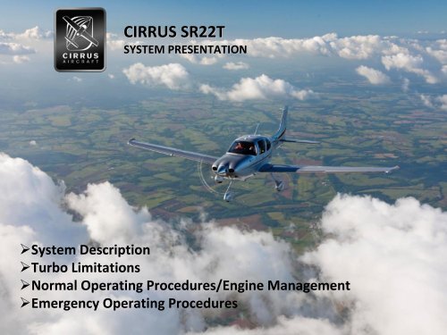
CIRRUS <strong>SR22T</strong><br />
SYSTEM PRESENTATION<br />
System Description<br />
<strong>Turbo</strong> Limitations<br />
Normal Operating Procedures/Engine Management<br />
Emergency Operating Procedures
KEY DESIGN<br />
FEATURES OF THE <strong>SR22T</strong><br />
ALL‐NEW ALL NEW TSIO‐550 TSIO 550‐K K ENGINE DEVELOPED SPECIFICALLY<br />
FOR CIRRUS IN PARTNERSHIP WITH <strong>TCM</strong>. THIS ENGINE IS<br />
2NOT<br />
NOT CURRENTLY IN ANY OTHER PRODUCTION AIRPLANE.
3<br />
KEY DESIGN<br />
ENGINE / MOUNTING SYSTEM<br />
MODIFIED NLG – OLEO STRUT<br />
FEATURES OF THE <strong>SR22T</strong>
4<br />
KEY DESIGN<br />
ENGINE / MOUNTING SYSTEM<br />
MODIFIED NLG – OLEO STRUT<br />
FEATURES OF THE <strong>SR22T</strong><br />
MODIFIED COWL
5<br />
KEY DESIGN<br />
ENGINE / MOUNTING SYSTEM<br />
MODIFIED NLG – OLEO STRUT<br />
FEATURES OF THE <strong>SR22T</strong><br />
MODIFIED ECS CONTROLLER<br />
MODIFIED COWL
<strong>SR22T</strong>: THE INTEGRATION<br />
SR22 AIRFRAME<br />
DESIGN DIFFERENCES:<br />
TWIN‐TURBOCHARGED TSIO‐550‐K ENGINE<br />
MODIFIED NOSE LANDING GEAR ‐ HYDRAULIC<br />
STRUT<br />
MODIFIED COWL WITH DEDICATED INDUCTION<br />
INLETS, DIFFERENT COOLING EXIT DESIGN<br />
MODIFIED ENVIRONMENTAL CONTROL SYSTEM<br />
CONTROLLER<br />
INTEGRATES SEAMLESSLY WITH
<strong>SR22T</strong>: MODIFIED COWL<br />
ENGINE INDUCTION FROM NACA INLETS<br />
COOLING EXIT CONFIGURATION
<strong>SR22T</strong>: NOSE LANDING GEAR<br />
HYDRAULIC SHOCK<br />
ABSORBING STRUT<br />
EXCEPTIONAL LANDING<br />
“FEEL” AND DAMPING IN<br />
CASE OF POOR LANDING<br />
REDUCED STRESS/LOADS<br />
INTO NLG WHICH<br />
PERMITTED WEIGHT<br />
REDUCTION OF NOSE<br />
STRUT<br />
FACILITATES DECREASE OF<br />
TAIL BALLAST WEIGHT<br />
NECESSARY FOR CG<br />
MANAGEMENT<br />
NET WEIGHT REDUCTION<br />
OF 10‐15 LBS
MODIFIED ECS CONTROLLER<br />
<strong>SR22T</strong><br />
LARGER HEAT EXCHANGER ON CROSSOVER TUBE, 50°F HIGHER<br />
HEAT RISE<br />
USES ELECTRONIC CONTROL TO ACTIVELY MONITOR AND BIAS<br />
VALVES IF HOT AIR TEMP EXCEEDS LIMITS<br />
BENEFITS ARE PLENTY OF HEAT ON THE GROUND, AND AT LOW<br />
AND HIGH ALTITUDES
<strong>SR22T</strong>: TSIO‐550 TSIO 550‐K K ENGINE<br />
<strong>TCM</strong> TYPE CERTIFIED ENGINE<br />
315 RATED HP @ 2500 RPM / 36.5” MAP<br />
ADDITIONAL TAKEOFF HP RESULTS IN NOMINAL<br />
IMPROVEMENT IN TAKEOFF AND CLIMB PERFORMANCE<br />
ENGINE COMPRESSION RATIO: 7.5:1<br />
PROVIDES HIGHER DETONATION PROTECTION, ENABLES<br />
ENGINE TO BE FLEXIBLE TO LOWER OCTANE UNLEADED<br />
FUELS
<strong>SR22T</strong>: TSIO‐550 TSIO 550‐K K ENGINE<br />
SINGLE WASTEGATE<br />
SMALL WEIGHT REDUCTION<br />
RELIABILITY AND MAINTENANCE BENEFITS<br />
CONSISTENT 2500 RPM FIXED GOVERNOR<br />
QUIET CABIN AND FLYOVER TAKEOFF AND CLIMB NOISE<br />
VERY LOW TAKEOFF AND CLIMB VIBRATION LEVELS<br />
SIMPLE SYSTEM RE: MAINTENANCE, RIGGING, SETUP<br />
WEIGHT SAVINGS: PROP CONTROL CABLE AND<br />
APPARATUS ~1.5 LBS<br />
PROP BRAKING: AT HIGH SPEED, LOW POWER BETTER<br />
DECELERATION
12<br />
so how does this <strong>all</strong> work?<br />
PUTTING IT TOGETHER
Air Intakes<br />
13<br />
•<br />
•<br />
2 combustion air intakes<br />
–<br />
1 on each side connected<br />
to NACA vent<br />
Fresh combustion air<br />
feeds directly into<br />
compressor‐side of turbo
Air Intakes<br />
14<br />
•<br />
•<br />
Flexible tube connects<br />
intakes<br />
Automatic alternate air<br />
door in center<br />
–<br />
–<br />
–<br />
–<br />
Held shut by<br />
spring/magnet<br />
Will open automatic<strong>all</strong>y<br />
when normal air sources<br />
become clogged<br />
Will close automatic<strong>all</strong>y<br />
when resistance is cleared<br />
CAS message will appear to<br />
alert pilot
Intercooler (Aftercooler)<br />
•<br />
•<br />
•<br />
As the air is compressed in the<br />
turbo, it also warms up (up to 5<br />
times as hot)<br />
Intercooler is inst<strong>all</strong>ed in the<br />
induction air path between the<br />
compressor and the throttle plate<br />
The function is to cool down the<br />
compressed air, which improves<br />
the performance of the engine
•<br />
•<br />
•<br />
OVER‐BOOST OVER BOOST VALVE<br />
An overboost pressure relief<br />
valve is incorporated on<br />
turbo<strong>charged</strong> engine models to<br />
prevent over pressurization of<br />
the induction system<br />
The overboost pressure relieve<br />
valve is set to open at roughly 2<br />
to 4 inches of mercury above the<br />
rated maximum manifold<br />
pressure of the engine<br />
This acts as a “fail safe” device to<br />
prevent the engine from reaching<br />
an overboost situation<br />
OPENING<br />
INDUCTION MANIFOLD<br />
AIR CAN ESCAPE<br />
SPRING<br />
AND BELLOWS<br />
VALVE
<strong>Turbo</strong>‐Supercharger<br />
<strong>Turbo</strong> Supercharger<br />
17<br />
•<br />
•<br />
•<br />
•<br />
<strong>Turbo</strong> uses accelerated exhaust gases<br />
to spin a compressor which increases<br />
the pressure in the upper deck<br />
Capable of +100,000 RPM<br />
Maximum Normal <strong>Turbo</strong> Inlet<br />
Temperature (TIT) is 1750°F, seen on<br />
MFD<br />
<strong>Turbo</strong> is lubricated via the engine oil<br />
system<br />
Combustion Air<br />
Exhaust
Wastegate<br />
•<br />
The waste‐gate is a<br />
hydraulic<strong>all</strong>y controlled<br />
device using engine oil<br />
pressure, to close a butterfly<br />
valve that will direct exhaust<br />
gasses to the turbocharger<br />
OIL “OUT” TO<br />
SLOPED CONTROLLER<br />
ENGINE OIL<br />
PRESSURE “IN”
Wastegate<br />
19<br />
•<br />
•<br />
•<br />
•<br />
•<br />
•<br />
The wastegate controls the amount<br />
exhaust that is <strong>all</strong>owed to flow<br />
through the turbo<br />
Air will take the path of least<br />
resistance<br />
A closed wastegate sends more<br />
exhaust through the turbo<br />
An opened wastegate <strong>all</strong>ows Exhaust<br />
to bypass the turbo and be dumped<br />
overboard<br />
A spring holds the wastegate in the<br />
open position. Oil pressure closes the<br />
wastegate<br />
There is only 1 wastegate that<br />
controls both turbos via a crossover<br />
tube
<strong>Turbo</strong> Operation<br />
20
Crossover Tube<br />
21<br />
•<br />
•<br />
The left and right<br />
exhaust manifolds<br />
are connected via a<br />
crossover tube<br />
This architecture<br />
equalizes exhaust<br />
pressure in the<br />
exhaust manifolds<br />
and both turbines<br />
are driven equ<strong>all</strong>y
SLOPE CONTROLLER<br />
22<br />
•<br />
•<br />
Moves the wastegate to manage<br />
the pressure created by the turbo<br />
Maintains a pressure differential<br />
across the throttle valve of <strong>about</strong><br />
4“ Hg at partial power settings<br />
and limits maximum MAP to<br />
36.5” at full power
SLOPE CONTROLLER<br />
23
SLOPE CONTROLLER<br />
24<br />
•<br />
•<br />
•<br />
On takeoff at full power, slope<br />
controller limits MAP to 36.5”<br />
As the aircraft climbs at full power<br />
and the ambient pressure decreases,<br />
the controller commands the<br />
wastegate to close to maintain 36.5”<br />
MAP<br />
As power is reduced, the controller<br />
commands the wastegate to open to<br />
maintain the 4” differential across<br />
the throttle plate<br />
ANEROID<br />
BELLOWS<br />
ASSEMBLY<br />
MANIFOLD<br />
PRESSURE<br />
SENSING<br />
PORT<br />
DIAPHRAGM<br />
DECK<br />
PRESSURE<br />
SENSING<br />
PORT<br />
OIL INLET<br />
PORT<br />
ADJUSTMENT<br />
SCREW<br />
POPPET<br />
POPPET SEAT<br />
OIL DRAIN<br />
PORT
Prop Governor<br />
The <strong>SR22T</strong> incorporates a cable‐less Hartzel propeller<br />
governor.<br />
The governor operates on the same principle as other<br />
propeller governors; sensing engine speed, the<br />
governor regulates pressurized engine oil in the<br />
propeller piston assembly, which controls propeller<br />
blade angle.<br />
Begins controlling blade angle and engine speed at<br />
approximately 1400 RPMs.<br />
The engine reaches its maximum speed of 2500 RPMs at<br />
power settings as low as 55%.<br />
As the power lever is advanced, engine speed will<br />
remain at 2500 RPMs, but MAP and Fuel flow will<br />
increase as will % Power.<br />
With the high speed stop set at 2500 RPMs, additional<br />
power input causes the governor to increase propeller<br />
blade angle, thus increasing thrust.
26<br />
<strong>SR22T</strong><br />
LIMITATIONS
Airspeed Limitations<br />
Speed KIAS Remarks<br />
Vne up to 17,500 MSL 200 Never Exceed<br />
Vne at 25,000 MSL 170 Vne is reduced linearly from<br />
17,500 to 25,000<br />
Vno up to 17,500 MSL 177 Maximum Structural Cruising<br />
Speed<br />
Vno at 25,000 MSL 151 Vno is reduced linearly from<br />
17,500 to 25,000<br />
Note: Vno and Vne can be interpolated for altitudes between 17,500 and 25,000.<br />
The PFD airspeed tape will change with altitude to reflect the difference in Vne / Vno
System Limitations<br />
• Altitude Limits<br />
– Maximum Takeoff Altitude…...………………..10,000 MSL<br />
– Maximum Operating Altitude...........................25,000 MSL<br />
• Flap Limitation<br />
– Do not use flaps above………………..............17,500 MSL<br />
• Environmental Conditions<br />
– Do not operate the aircraft below an outside air temperature of -<br />
40°C<br />
• Do not reduce manifold pressure below 15” when above 18,000 ft<br />
MSL
Critical Altitude<br />
• Critical altitude is defined as the altitude at which<br />
the wastegate is completely closed and as the<br />
aircraft continues to climb, MAP will begin to<br />
decrease<br />
• Critical altitude is 18,000 ft<br />
• Aircraft will still be able to maintain 31” MAP and<br />
85% power at 25,000 ft
30<br />
lean of peak operations<br />
ENGINE MANAGEMENT
Operations Lean of Peak (EGT)<br />
31<br />
Note:<br />
• Close relationship of<br />
CHT, ICP, HP<br />
• Order of peaks- HP,<br />
ICP, CHT, EGT<br />
• Curvature of peaks on<br />
the rich and lean side of<br />
peak<br />
• Rich of peak<br />
– Leaner increases CHT<br />
• Lean of peak<br />
– Leaner decreases<br />
CHT
Engine Roughness at Lean of Peak<br />
32<br />
• Caused by<br />
unbalanced fuel/air<br />
ratios<br />
• More apparent<br />
during lean of peak<br />
operations<br />
• Why?<br />
– Remember the HP<br />
curve in relation the<br />
fuel/air ratios<br />
Unbalanced Injectors<br />
40 HP<br />
55 HP<br />
60 HP<br />
315 HP<br />
total output<br />
45 HP<br />
50 HP<br />
65 HP
Unbalanced Fuel/Air Ratios<br />
• Some cylinders receive more<br />
fuel than others<br />
– ROP, Same HP / Smooth<br />
– LOP, Varying HP / Rough<br />
Unbalanced Injectors ROP<br />
53 HP<br />
53 HP<br />
52 HP<br />
Unbalanced Injectors LOP<br />
40 HP<br />
55 HP<br />
60 HP<br />
315 HP<br />
Total Output<br />
315 HP<br />
Total Output<br />
52 HP<br />
53 HP<br />
52 HP<br />
45 HP<br />
50 HP<br />
65 HP<br />
•Varying HP<br />
•Rough Engine Operation<br />
•Same HP<br />
•Smooth Engine Operation
Balanced Fuel/Air Ratios<br />
34<br />
• Each cylinder receiving<br />
same amount of fuel<br />
and air.<br />
• All cylinders developing<br />
equal HP even on steep<br />
LOP curve.<br />
Balanced Injectors LOP & ROP<br />
53 HP<br />
53 HP<br />
52 HP<br />
315 HP<br />
Total Output<br />
52 HP<br />
53 HP<br />
52 HP
35<br />
differences from natur<strong>all</strong>y aspirated engine operations<br />
NORMAL OPERATIONS
Preflight<br />
• O 2 preflight<br />
– O 2 quantity, requirements<br />
and duration tables<br />
– Verify O 2 flow to each<br />
mask/cannula that will be<br />
used<br />
• Pulse Oximeter<br />
– Check saturation levels on<br />
the ground and monitor<br />
during flight.<br />
– Adjust O 2 flow to maintain<br />
saturation levels above 90%<br />
• Cannulas can not be used<br />
above FL180 as per FAR part<br />
23. Masks must be worn<br />
above FL180. Plan<br />
accordingly.
Oxygen Considerations<br />
• Do not use cannulas above FL180<br />
• Passengers should be thoroughly briefed on the use of<br />
O 2 including:<br />
– Proper use of masks/cannulas and flow regulators<br />
– Recognition and response to hypoxia<br />
– Recognition and response to pilot incapacitation<br />
• If saturation levels decrease below 90%<br />
– Increase to flow of O 2<br />
– Increase mask seal around face<br />
– Descend to a lower altitude if saturation level can not be<br />
maintained above 90%
Normal Procedures<br />
• Start<br />
– No Change<br />
• Taxi<br />
– Lean to the “X” or max RPM<br />
• Before takeoff<br />
– No Change<br />
– Ensure oil temperature is above 100° F before run up
Takeoff<br />
• Full throttle<br />
• Full mixture (for every altitude)<br />
• Boost pump on<br />
• Monitor MP for overboost<br />
– If the MP exceeds 37.0 inches reduce the throttle below 37.0<br />
inches of MP<br />
– Due to cooler oil temperatures<br />
• Monitor Fuel Flow (Green Arc)<br />
– Will increase in proportion to manifold pressure
Normal Procedures- Procedures Climb<br />
• Full Power Climb: Rich of Peak Technique<br />
– Power Lever – Full Forward<br />
– Mixture – Maintain Fuel Flow w/in Green Arc<br />
– CHT – Maintain below 420° F<br />
• Airspeed 120-130<br />
• Cruise Climb: Lean of Peak Technique<br />
– Power Lever – 30.5” MAP<br />
– Mixture – Cyan Target or less<br />
– CHT – Maintain below 420 ° F<br />
• Airspeed 120-130<br />
• Lean as required to maintain
Full Power Climb vs. Lean of Peak Climbs<br />
Cruise Altitude (MSL) Fuel Savings LOP (G<strong>all</strong>ons) Range Increase LOP (NM)<br />
2,000 .4 4<br />
4,000 .7 8<br />
6,000 1 13<br />
8,000 1.4 17<br />
10,000 1.8 23<br />
12,000 2.1 27<br />
14,000 2.5 33<br />
16,000 2.9 38<br />
18,000 3.3 44<br />
20,000 3.6 52<br />
22,000 4.2 59<br />
24,000 4.7 67<br />
25,000 5.1 71
Full Power Climb vs. Lean of Peak Climb<br />
Consider the following factors when deciding to<br />
climb LOP or ROP<br />
•Workload associated with LOP climbs<br />
– Closely monitor CHT’s<br />
– Adjusting mixture/airspeed for cooling<br />
•Decrease in climb performance<br />
•Significance of fuel savings<br />
•Significance of extra range
Normal Procedures- Procedures Cruise<br />
• Cruise- Power settings will be lean of peak<br />
– Power Lever – 30.5” MAP or less<br />
– Fuel pump- As required<br />
• Low boost for at least 30 minutes<br />
– Mixture – Cyan target or less<br />
• 50 °-75°F lean of peak TIT<br />
– CHT’s – Maintain below 420 ° F<br />
• IF CHT’s are greater than 420 °F then lean .5 GPH<br />
– Should result in a 15 °F reduction in CHT temperature for every .5 GPH<br />
• 390° - 400°F CHT’S TYPICAL
Boost Pump Operation<br />
• Pressure affects the temperature required to vaporize<br />
fuel<br />
– Lower pressure = lower vaporization temperature<br />
• Low boost provides extra pressure to keep fuel from<br />
vaporizing at high altitude<br />
• High boost may be necessary above FL180 with warm<br />
or hot fuel if vapor lock is present<br />
• Vapor lock can be recognized in flight by:<br />
– Fluctuations in normal fuel flow<br />
– Rising EGTs and TIT coupled with f<strong>all</strong>ing fuel flow<br />
– Rising CHTs
Normal Procedures<br />
• Descent<br />
– Power Lever – As Required<br />
– Mixture – Cyan Target or less<br />
– CHT – Maintain in green arc (above 240° F)<br />
– Avoid Prolonged idle settings<br />
• Rapid Descent<br />
– Power lever- Smoothly reduce MAP 18 to 20”<br />
– Mixture – Maintain CHT’s above 240 ° F<br />
• Approach/Landing<br />
– Mixture full rich prior to traffic pattern or IAF
Normal Procedures<br />
• After Landing<br />
– Mixture – Lean to X or max RPM rise<br />
• Shutdown<br />
– No change
True or False?<br />
• Leaning the engine will cause the CHT’s to rise<br />
when operating lean of peak.<br />
See speaker notes for answer.
Scenario<br />
During a lean of peak climb while climbing at 120<br />
KIAS the CHT’s exceed 420° F<br />
– What is the appropriate response?<br />
– What if that does not work?<br />
– What if that does not work?<br />
See speaker notes for answer
Scenario<br />
After setting cruise power at 85% (2500RPM /<br />
30.5” MP and 18.3 GPH) the CHT’s remain at<br />
420° F.<br />
– What is the appropriate action?
Emergency Procedures<br />
Specific to <strong>Turbo</strong> Operations
Scenario<br />
• While cruising at 17,000ft <strong>you</strong> notice a sudden<br />
loss of manifold pressure.<br />
– What do <strong>you</strong> do now?
Unexpected Loss of Manifold Pressure<br />
• Four Most Probable Causes<br />
1. Leak in the induction system<br />
• Behaves like a norm<strong>all</strong>y aspirated airplane<br />
2. Leak in the exhaust system<br />
• Possible fire hazard<br />
3. Loss of oil pressure to wastegate actuator<br />
• Due to general loss of engine oil<br />
4. Failure of internal component in turbocharger<br />
• May be accompanied by loss of oil pressure
Unexpected Loss of Manifold Pressure<br />
Emergency Procedure:<br />
1. Power- Adjust to minimum required<br />
2. Mixture-Adjust for EGT’s between 1300 ° to 1400 °F<br />
3. Descend to Minimum Safe Altitude from which a<br />
landing may be safely accomplished<br />
4. Divert to nearest suitable airfield<br />
5. Radio-121.5 advise ATC<br />
6. Oil Pressure-Monitor<br />
7. Land as soon as possible
Scenario<br />
Shortly after leveling out at 22,000 <strong>you</strong> set the<br />
cruise power, lean the mixture and turn <strong>you</strong>r<br />
boost pump off and <strong>you</strong>r engine fails.<br />
– What do <strong>you</strong> do?<br />
– Why did the engine fail?<br />
See speaker notes for answer.
Engine Failure<br />
• One cause of engine failure may be from reducing the power to idle<br />
with the mixture set near or at full rich. Altitude and fuel pump<br />
operation will affect the failure conditions.<br />
Note: The cause of the engine failure is an excessively rich mixture of<br />
fuel and air, essenti<strong>all</strong>y flooding the engine.<br />
Note: If this is not cause of the failure refer to the engine failure in flight<br />
checklist procedure.<br />
• First reaction to failure<br />
– Increase throttle control<br />
• If that does not work<br />
– Auxiliary fuel pump off<br />
– Throttle ½ open<br />
– Mixture control lean until engine starts<br />
– Throttle, mixture and fuel pump reset for normal operation.<br />
• Richen the mixture slowly after engine start then increase the throttle.