Application of MDO to Large Subsonic Transport Aircraft
Application of MDO to Large Subsonic Transport Aircraft
Application of MDO to Large Subsonic Transport Aircraft

Create successful ePaper yourself
Turn your PDF publications into a flip-book with our unique Google optimized e-Paper software.
I<br />
(c)2000 American Institute <strong>of</strong> Aeronautics & Astronautics or published with permission <strong>of</strong> author(s) and/or author(s)’ sponsoring organization.<br />
AIAA 2000-0844<br />
<strong>Application</strong> <strong>of</strong> MD0 <strong>to</strong> <strong>Large</strong><br />
<strong>Subsonic</strong> <strong>Transport</strong> <strong>Aircraft</strong><br />
A. Van der Velden<br />
Synaps, Inc.<br />
Atlanta, GA<br />
R. Kelm<br />
Daimler-Chrysler Aerospace Airbus<br />
Hamburg, Germany<br />
D. Kokan<br />
Synaps, Inc.<br />
Atlanta, GA<br />
J. Mertens<br />
Daimler-Chrysler Aerospace Airbus<br />
Hamburg, Germany<br />
38th Aerospace Sciences<br />
Meeting & Exhibit<br />
1 O-1 3 January 2000 / Reno, NV<br />
A0046683<br />
For permission <strong>to</strong> copy or republish, contact the American Institute <strong>of</strong> Aeronautics and Astronautics<br />
1801 Alexander Bell Drive, Suite 500, Res<strong>to</strong>n, VA 20191
(c)2000 American Institute <strong>of</strong> Aeronautics & Astronautics or published with permission <strong>of</strong> author(s) and/or author(s)’ sponsoring organization.<br />
Alexander Van der Velden<br />
Roland Kelm<br />
David Kokan<br />
Josef Mertens<br />
AMA-2000-0844<br />
<strong>Application</strong> <strong>of</strong> MD0 <strong>to</strong> <strong>Large</strong> <strong>Subsonic</strong><br />
<strong>Transport</strong> <strong>Aircraft</strong><br />
Synaps, Inc., velden@synaps-inc.com<br />
president-<br />
Daimler-Chrysler Aerospace Airbus, Hamburg, Germany<br />
head aeroelastic structures<br />
Synaps, Inc.<br />
senior consultant<br />
Daimler-Chrysler Aerospace Airbus, Bremen, Germany<br />
RAWID project manager aerophysics division<br />
Daimler-Chrysler Aerospace Airbus and Synaps developed a preliminary design <strong>to</strong>ol <strong>to</strong> quickly trade-<strong>of</strong>f wing<br />
planform, thickness and lift distribution on a large commercial passenger transport wing. Goal <strong>of</strong> this study was <strong>to</strong><br />
minimize the weight <strong>of</strong> the wing structure + fuel at a constant maximum take<strong>of</strong>f weight. The design study was<br />
performed with the PointerTM MD0 framework s<strong>of</strong>tware. Pointerm couples the required analysis codes and<br />
searched the design space for the best solution. The section drag was determined using a large database <strong>of</strong> swept<br />
airfoils that were shape optimized for specific design conditions. The wing loads and induced drag were<br />
determined with a vortex-lattice code. The weight <strong>of</strong> the wing was estimated using the Airbus FAME s<strong>of</strong>tware<br />
which sizes the wing primary and secondary structure based on the wing loads with static aero-elastic effects. The<br />
present method used led <strong>to</strong> significant performance improvements (which were confirmed by later detailed<br />
studies) and a better understanding <strong>of</strong> what drives the design <strong>of</strong> very large transports. As compared <strong>to</strong><br />
conventional design iterations performed by teams <strong>of</strong> experts, the present method requires only half the time per<br />
design cycle and a fraction <strong>of</strong> the number <strong>of</strong> design cycles <strong>to</strong> converge the design.<br />
Introduction<br />
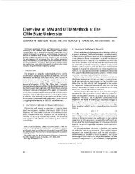
The design <strong>of</strong> a new very large transport [Fig. 1,<br />
Ref. 131 poses several challenges <strong>to</strong> the<br />
conventional method. In the conventional<br />
approach, the preliminary design department<br />
proposes an initial description <strong>of</strong> the design <strong>to</strong><br />
the aerodynamic design team. This team finishes<br />
a full aerodynamic design optimization for this<br />
configuration and then passes this detailed<br />
geometry <strong>to</strong> the structural design group who<br />
compute the required weights. However, in the<br />
case <strong>of</strong> very large aircraft, many detailed design<br />
cycle iterations (>lO) were required <strong>to</strong> converge<br />
<strong>to</strong> an optimal design. One <strong>of</strong> the reasons for that<br />
is because the initial preliminary design does not<br />
include the right level <strong>of</strong> physical modeling <strong>to</strong><br />
trade-<strong>of</strong>f design decisions for a very large<br />
transonic aircraft.<br />
1<br />
American Institute for Aeronautics and Astronautics<br />
Fig 1: Proposal for a new large aircraft<br />
(pho<strong>to</strong> Airbus industrie)<br />
This problem is the most pressing for wing<br />
design. Therefore, in the past 6 years significant<br />
effort has been invested <strong>to</strong> create preliminary<br />
design <strong>to</strong>ols that accurately predict the<br />
aerodynamic and structural potential <strong>of</strong> well<br />
designed transonic aircraft wings. With these
(c)2000 American Institute <strong>of</strong> Aeronautics & Astronautics or published with permission <strong>of</strong> author(s) and/or author(s)’ sponsoring organization.<br />
<strong>to</strong>ols it is possible <strong>to</strong> make accurate trade<strong>of</strong>f<br />
studies using multi-disciplinary optimization<br />
technology in the initial stage <strong>of</strong> aircraft<br />
definition. This <strong>to</strong>ol is similar <strong>to</strong> the MIDAS <strong>to</strong>ol<br />
[5] developed in the early ‘90s <strong>to</strong> design the<br />
Present Method<br />
In order <strong>to</strong> increase the accuracy <strong>of</strong> the initial<br />
preliminary design trade-<strong>of</strong>f, we developed a new<br />
wing preliminary design <strong>to</strong>ol. This is achieved by<br />
increasing the physical fidelity <strong>of</strong> the models and<br />
by using multi-disciplinary design optimization.<br />
This <strong>to</strong>ol was comprised out <strong>of</strong> three parts:<br />
a) Pointer MD0 framework. The purpose <strong>of</strong><br />
this <strong>to</strong>ol is <strong>to</strong> execute computer simulations<br />
more efficiently, and <strong>to</strong> search the design<br />
space created with the outputs <strong>of</strong> these<br />
simulations for the best solution.<br />
b) FAME-W weight and loads model<br />
developed by DASA-Airbus Hamburg. It<br />
determines the potentially best structural<br />
weight for a well designed aero-elastically<br />
deforming wing using only a preliminary<br />
description <strong>of</strong> the structure and ,aircraft<br />
mission.<br />
c) Globair aerodynamics model developed by<br />
Synaps and DASA-Airbus Bremen. It<br />
determines the potentially lowest transonic<br />
drag for a well designed wing for a given<br />
mission point using only a preliminary<br />
description <strong>of</strong> the wing surface.<br />
Pointer as a <strong>to</strong>ol <strong>to</strong> perform design studies.<br />
Pointer [6,9] is an MD0 framework <strong>to</strong>ol. MD0<br />
framework <strong>to</strong>ols are explained in detail by Salas<br />
and Townsend in ref. [7]. The development <strong>of</strong><br />
Pointer was driven by the following<br />
consideration:<br />
Pointer should give the expert user the ability <strong>to</strong><br />
find a better answer <strong>to</strong> a wide class <strong>of</strong> complex<br />
design problems in less time than it would take<br />
him <strong>to</strong> solve the problem in a conventional way.<br />
2<br />
American Institute for Aeronautics and Astronautics<br />
DASA & European supersonic transports.<br />
However because subsonic transports are much<br />
more mature, a much higher accuracy in the<br />
physical modeling is required <strong>to</strong> achieve<br />
(typically smaller) performance gains.<br />
Therefore, the setup <strong>of</strong> the design problem<br />
should be as user-friendly as possible. In terms <strong>of</strong><br />
the s<strong>of</strong>tware architecture Pointer achieves this by<br />
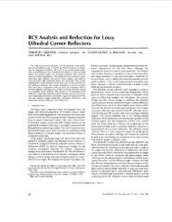
using intuitive GUI’s [Fig 21, object oriented<br />
principles and the use <strong>of</strong> s<strong>of</strong>tware standards.<br />
Pointer au<strong>to</strong>matically parses the parameters<br />
defining the input <strong>to</strong> legacy and proprietary<br />
codes. Pointer also controls the running <strong>of</strong> these<br />
codes both in sequence and parallel.<br />
After all the I/O is defined, the design problem is<br />
stated in the form <strong>of</strong> an objective, design<br />
variables and constraints. It is here that most<br />
users have problems and we consider this the<br />
major hurdle in the development <strong>of</strong> MD0<br />
technology.<br />
In his paper “On making things best” [lo] Holt<br />
Ashley said it all, when he stated the omission <strong>of</strong><br />
the optimization algorithm description in a<br />
design study a “charming sign <strong>of</strong> maturity”. In<br />
Pointer a hybrid combination <strong>of</strong> the best current<br />
optimization algorithms [Linear Programming,<br />
Sequential Quadratic Programming, Gradient,<br />
Downhill-simplex and Genetic] are used <strong>to</strong> solve<br />
the problem. The program does not require any<br />
intervention from the user or specialist know-<br />
ledge about optimization. In our experience,<br />
Pointer requires T hours <strong>to</strong> solve the problem:<br />
T = Z * #variables *Time-per-design- simulation<br />
Z, the relative complexity <strong>of</strong> the problem, is<br />
typically 100, the first time a strongly non-linear<br />
engineering problem is solved. We see the initial<br />
investment <strong>of</strong> so many function calls as essential<br />
<strong>to</strong> understanding the problem posed by the<br />
<strong>to</strong>pography <strong>of</strong> the objective function. In practice<br />
if the computer simulation takes more than I<br />
hour, parallel processing <strong>of</strong> the design simulation<br />
is required <strong>to</strong> avoid excessive run-times.<br />
In subsequent uses, Pointer learns from its<br />
experience and typically reduces Z <strong>to</strong> a number<br />
below 10. This saves a lot <strong>of</strong> time when<br />
optimizations are repeated, for instance when an<br />
optimal design database is created.
(c)2000 American Institute <strong>of</strong> Aeronautics & Astronautics or published with permission <strong>of</strong> author(s) and/or author(s)’ sponsoring organization.<br />
Weights & Loads Model FAME-W<br />
The Airbus FAME-W preliminary weight model<br />
is described in detail in ref [ 1,2] The current<br />
description explains how this model was used in<br />
the present study. For the design <strong>of</strong> a real wing<br />
structure, the complete load case spectrum must<br />
be investigated, including gust, maneuver and<br />
landing in terms <strong>of</strong> both static and dynamic aero-<br />
elastics. In this particular study, only the 2Sg<br />
maneuver case at sea level .and maximum<br />
dynamic pressure with static aeroelastic<br />
deformations at cruise and maneuver were<br />
considered. Nevertheless, the current level <strong>of</strong><br />
detail is sufficient <strong>to</strong> support the conclusions <strong>of</strong><br />
this paper.<br />
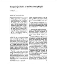
Fig. 3 shows the FAME-W structural wing<br />
design process. The cruise wing lift distribution<br />
is an input <strong>to</strong> the weight model FAME. Finding<br />
the twist distribution <strong>of</strong> the unloaded wing (jig<br />
shape) is not a trivial task, because there is<br />
already significant elastic deformation at the<br />
cruise condition. To solve this problem, initial<br />
values for the stiffness and the structural relief<br />
are estimated with a pre-dimensioning model.<br />
The accuracy <strong>of</strong> these values influences the<br />
speed <strong>of</strong> convergence <strong>of</strong> all following<br />
calculations.<br />
After the first twist distribution <strong>of</strong> the jig shape<br />
has been found, the primary structural<br />
components can be dimensioned. In this process<br />
a new stiffness and mass distribution is found.<br />
In the ‘loads loop’, the loads on the twisted wing<br />
are calculated using the Truckenbrodt vortex-<br />
lattice model [3]. The stiffness values are kept<br />
constant in this iteration loop. In the final step,<br />
the stiffness calculation, the stress distribution in<br />
the wing box and the required. material cross-<br />
sections are determined iteratively for the given<br />
loads. If in this process the stiffness distribution<br />
changes significantly, the loads calculation must<br />
be repeated, because the deformation behavior,<br />
and thus the loads, change.<br />
The converged stiffness distribution differs from<br />
the stiffness distribution used on the calculation<br />
<strong>of</strong> the jig shape. Therefore, a re-twist <strong>of</strong> the wing<br />
is performed and the loads loop is repeated.<br />
Within the loads calculation the deformation<br />
through bending and <strong>to</strong>rsion influences the zero<br />
moment coefficient <strong>of</strong> the wing. This in turn<br />
changes the trim state <strong>of</strong> the aircraft, specifically,<br />
the loads on the tail and wing. After these effects<br />
are taken in<strong>to</strong> account and the whole solution is<br />
converged, the influence <strong>of</strong> static aeroelastic<br />
deformations on the aircraft performance can bc<br />
estimated.<br />
Globair Drag Model<br />
American Institute for Aeronautics and Astronautics<br />
In the preliminary design phase the wing is only<br />
described in terms <strong>of</strong> planform, thickness<br />
distribution, load distribution and mission<br />
discription. This is adequate for the evaluation <strong>of</strong><br />
the wing weight, but not adequate <strong>to</strong> determine<br />
the transonic drag. The transonic drag is<br />
dependent on the detailed (curvature) shape <strong>of</strong><br />
the wing.<br />
It would be beyond the scope <strong>of</strong> a preliminary<br />
design method <strong>to</strong> include the detailed curvature<br />
<strong>of</strong> the wing. The purpose <strong>of</strong> this model is <strong>to</strong><br />
predict the wing drag which the detailed<br />
aerodynamic design will achieve but even before<br />
the detailed aerodynamic design is started.<br />
We noticed that though transonic aerodynamic<br />
designs are designed with respect <strong>to</strong> many<br />
operating points, the wave drag at the principal<br />
cruise operating point is very close <strong>to</strong> the<br />
minimal achievable wave drag. This is easily<br />
unders<strong>to</strong>od since subsonic long range transports<br />
spend most <strong>of</strong> their time at this operating<br />
condition. We therefore created a model that<br />
predicted the minimal achievable transonic drag<br />
as a function <strong>of</strong> wing preliminary design<br />
parameters.<br />
The model was created with a database <strong>of</strong> 240<br />
airfoils. Each airfoil had been au<strong>to</strong>matically<br />
designed for minimum drag under representative<br />
specific operating condition [CL, M, Re] and<br />
geometric constraints [t/c, flap spar heights]. The<br />
creation <strong>of</strong> such a large database was possible<br />
through the use <strong>of</strong> the au<strong>to</strong>matic aerodynamic<br />
shape optimization with Pointer as described in<br />
ref. [4, 81.<br />
This database also clearly showed that the type <strong>of</strong><br />
optimal pressure distribution is very dependent<br />
on the operating condition and that attempts <strong>to</strong><br />
design this database using ‘perceived good’
(c)2000 American Institute <strong>of</strong> Aeronautics & Astronautics or published with permission <strong>of</strong> author(s) and/or author(s)’ sponsoring organization.<br />
pressure distributions is probably impossible.<br />
The individual design solutions were compared<br />
<strong>to</strong> DASA experience.<br />
The 2D database was then approximated with a<br />
suitable response surface. For a given planform,<br />
thickness and load distribution, the equivalent 2D<br />
flow conditions on a straight tapered section <strong>of</strong><br />
the wing can be determined using the sweep<br />
angle <strong>of</strong> the shock. Since we know the location<br />
<strong>of</strong> the shock on the chord for each airfoil in the<br />
database, its shock sweep can be determined<br />
iteratively for each combination <strong>of</strong> a straight<br />
taper section and airfoil.<br />
Fig. 2 Pointer MD0 framework<br />
4<br />
American Institute for Aeronautics and Astronautics<br />
The 2D airfoil wave drag <strong>of</strong> this wing section is<br />
known from the response surface model and this<br />
can be converted in<strong>to</strong> a 3D value using a<br />
modified version <strong>of</strong> R.T. Jones’s and Boppe’s<br />
[I I] sweep-taper theory and the value <strong>of</strong> the<br />
shock sweep. The friction drag was determined<br />
based on the 2D strip friction drag coefficient<br />
predicted by the response surface model.<br />
The induced drag is calculated using the<br />
Truckenbrodt [3] vortex lattice induced drag<br />
model which includes the effect <strong>of</strong> the tail.
(c)2000 American Institute <strong>of</strong> Aeronautics & Astronautics or published with permission <strong>of</strong> author(s) and/or author(s)’ sponsoring organization.<br />
Aerodynamic design<br />
Fliaht oerformance CalCulatiOn<br />
. Intluence.<strong>of</strong> flexlbiltty during<br />
. Rudder eflectiveness<br />
! I . Stability problem (tluI7erl ;<br />
I I<br />
Fig. 3 FAME-W design process<br />
Applka%on io a <strong>Large</strong> <strong>Transport</strong><br />
Problem description<br />
Structure dimensioning ----+ Weights<br />
Jig shape calculabor<br />
I]<br />
+,<br />
(Wing]<br />
‘+,<br />
1:<br />
_ _I Mcdly sthess _;<br />
/ and/or mass I<br />
To demonstrate the use <strong>of</strong> this <strong>to</strong>ol we posed the<br />
following test-problem.<br />
What preliminary design <strong>of</strong> the wing produces<br />
the minimum weight <strong>of</strong> the wing’ + fuel <strong>to</strong><br />
perform the harmonic mission (maximum<br />
payload) <strong>of</strong> a 5.50 pax very large transport? The<br />
maximum payload (in fuselage) mission is the<br />
most critical for the wing structure. We also<br />
wanted <strong>to</strong> know the sensitivity <strong>of</strong> this design <strong>to</strong><br />
errors made in the prediction <strong>of</strong> wing weight and<br />
drag.<br />
5<br />
American Institute for Aeronautics and Astronautics<br />
:<br />
t<br />
A<br />
Loads loop<br />
(Ior each in&&al load case)<br />
Loads calculallon<br />
Stilfness calculation<br />
(loads constant)<br />
-I<br />
(Wing]<br />
t@i<br />
piiziq<br />
The wings own structural weight plus the weight<br />
<strong>of</strong> the fuel it carries represents half the maximum<br />
take<strong>of</strong>f weight <strong>of</strong> the aircraft. It is therefore clear<br />
that the wing represents the most critical<br />
component <strong>of</strong> the aircraft.<br />
The reference configuration we used was the<br />
current status (1998) <strong>of</strong> the design shown in Fig.<br />
1 [13].<br />
The following parameters were picked <strong>to</strong><br />
describe the preliminary wing design <strong>of</strong> the type<br />
<strong>of</strong>Fig. 1.
(c)2000 American Institute <strong>of</strong> Aeronautics & Astronautics or published with permission <strong>of</strong> author(s) and/or author(s)’ sponsoring organization.<br />
a) 1 Load distribution parameter p. This<br />
allowed the wing load distribution <strong>to</strong> vary<br />
from over-elliptic <strong>to</strong> under elliptic.<br />
b) 4 Wing planform parameters: Aspect ratio,<br />
Root chord, outboard taper ratio and sweep.<br />
Planform changes were performed such that<br />
the wing area remained constant.<br />
c) 2 Thickness parameters: Root thickness-<strong>to</strong>-<br />
chord ratio, Kink thickness-<strong>to</strong> chord ratio.<br />
The thickness was assumed <strong>to</strong> vary in a fixed<br />
parametric way from the root <strong>to</strong> the kink and<br />
the kink <strong>to</strong> the tip.<br />
Execution <strong>of</strong> the study<br />
With our present method we first analyzed the<br />
performance <strong>of</strong> the reference configuration. The<br />
predicted weight and drag ‘were very good.<br />
Cruise drag and weight were predicted with an<br />
error <strong>of</strong> around 2% as compared <strong>to</strong> the best<br />
available numbers for the reference<br />
configuration. The numbers were calibrated <strong>to</strong><br />
correspond exactly <strong>to</strong> the reference aircraft<br />
performance.<br />
Next, parametric scans were performed <strong>of</strong> the<br />
design parameters. The results were quite<br />
surprising. Fig. 4 showed that for the reference<br />
aircraft the aspect ratio had <strong>to</strong> be reduced from 8<br />
<strong>to</strong> 6 <strong>to</strong> achieve the minimum objective function<br />
values (wing weight + fuel weight). In this case,<br />
the objective function was only reduced by 5 <strong>to</strong>ns<br />
in absolute terms. After performing an<br />
optimization <strong>of</strong> the design parameters the scan <strong>of</strong><br />
the aspect ratio showed that the original aspect<br />
ratio was indeed the best one, but only in<br />
combination with other values for the other<br />
design parameters. This exercise again shows the<br />
dangers <strong>of</strong> relying on 1-D parametric scans <strong>to</strong><br />
drive such non-linear designs.<br />
Next a matrix <strong>of</strong> 9 scenarios, each with 9 sub-<br />
scenarios (81 cases) was investigated. The<br />
scenarios covered expected uncertainties in both<br />
the wing structural mass (as predicted by FAME)<br />
and the cruise fuel mass due <strong>to</strong> aerodynamic<br />
performance (as predicted by Globair). The<br />
combination <strong>of</strong> all these scenarios covered all<br />
expected analysis errors.<br />
Fig 5. shows the result. All optimal wings<br />
showed significant improvements with respect <strong>to</strong><br />
the reference wing. This was true even if it was<br />
assumed (in the extreme case) that both the<br />
aerodynamic and structural benefits predicted by<br />
the analysis were 20% lower in each case than<br />
computed. The (analysis = true) point shows the<br />
performance <strong>of</strong> the optimized wing assuming that<br />
the analyses were correct.<br />
The solutions that get most <strong>of</strong> their benefit out <strong>of</strong><br />
the reduction <strong>of</strong> the wing structural mass are<br />
called “structures solutions”. The solutions that<br />
get most <strong>of</strong> their benefit (in terms <strong>of</strong> the<br />
objective function) out <strong>of</strong> the reduction <strong>of</strong> the<br />
fuel weight are called “aero solutions”.<br />
Selection <strong>of</strong> the best design<br />
6<br />
American Institute for Aeronautics and Astronautics<br />
Since we felt that all scenarios were equally<br />
likely <strong>to</strong> be true, we were interested in whether<br />
we could find a design that was most likely <strong>to</strong><br />
produce good performance. We did this by<br />
identifying the range <strong>of</strong> optimal design<br />
parameters for the different scenarios. Fig. 6<br />
shows the result.<br />
This showed that for three design parameters the<br />
direction <strong>of</strong> change was irrespective <strong>of</strong> the<br />
scenario. The load parameter was changed the<br />
most. The optimal design very likely had more<br />
load on the inboard wing than the reference<br />
design. Also the sweep was increased and the<br />
root chord decreased for all designs.<br />
Fig. 7 shows why it is so important <strong>to</strong> have an<br />
inboard shifted load distribution for this type <strong>of</strong><br />
aircraft. First <strong>of</strong> all, moving the load from the<br />
outboard wing <strong>to</strong> the inboard wing reduces the<br />
wing bending moments and decreases wing<br />
weight. Secondly, the nose-up pitching moment<br />
causes a reduction in the tail down loads and<br />
therefore reduces the load on the wing required<br />
<strong>to</strong> pull 2.5 g’s Thirdly, induced drag <strong>of</strong> an<br />
inboard loaded wing + downloaded tail is not<br />
very different from the ideal induced drag. This<br />
can be easily unders<strong>to</strong>od by applying Munk’s<br />
theorem [ 121.<br />
A year before this study was completed (1997)<br />
the second author had already proposed this<br />
design modification. This was not adopted at that<br />
time because shifting the load inboard caused<br />
significant additional wave drag.
(c)2000 American Institute <strong>of</strong> Aeronautics & Astronautics or published with permission <strong>of</strong> author(s) and/or author(s)’ sponsoring organization.<br />
The present study however, suggested modifying<br />
the wing load distributiort’the wing sweep and<br />
the root chord simultaneously. This new<br />
planform design is shown in Fig. 8. The kink<br />
region was not very noticeable in the planform<br />
view any more and the wing sweep is increased a<br />
few degrees. The wing thickness ratio was not<br />
changed much. If we analyzed these design<br />
changes with our preliminary code we would get<br />
a performance gain <strong>of</strong> not less than 10,000 kg for<br />
every scenario.<br />
Verification <strong>of</strong> the design performance<br />
At this point the new preliminary design was<br />
finished. It was however hard <strong>to</strong> predict whether<br />
the large performance improvements were real.<br />
For that purpose a detailed design needed <strong>to</strong> be<br />
made. So we needed a detailed aerodynamic<br />
design based on the same specifications (multi-<br />
points) as the original reference design and<br />
analyzed with the same codes as the reference<br />
design. We used the Pointer-Aeropt code (as<br />
described in ref. 8.) <strong>to</strong> design the detailed<br />
aerodynamic shape <strong>of</strong> the wing using 130 shape<br />
variables and 3 critical operating conditions. The<br />
start configuration for the detailed aerodynamic<br />
12000 --<br />
Total Mass versus AR<br />
(reference)<br />
Mass 8000 --<br />
6000 --<br />
current value<br />
(kg) 4000 --<br />
2000 - -<br />
0 --<br />
5.00 6.00 7.00 8.00 9.00<br />
AR<br />
Fig. 4 1-D scan <strong>of</strong> the aspect ratio before and after the optimization.<br />
design loop used scaled A340 type airfoil<br />
sections. The drag <strong>of</strong> that wing was 30% higher<br />
than the reference configuration. After 2 cycles<br />
(1 month) the design had converged <strong>to</strong> a shape<br />
that produced a drag that was 5% lower than the<br />
drag predicted for .the reference configuration<br />
with the same (Navier S<strong>to</strong>kes) code. This<br />
configuration is shown in Fig 9. Since we now<br />
also had the detailed section shapes we could<br />
repeat the application <strong>of</strong> the structural design and<br />
weight estimation <strong>to</strong>ol FAME with more<br />
accuracy.<br />
The overall performance gain was slightly higher<br />
than the 10 <strong>to</strong>ns predicted. The improvement<br />
came equally from the drag and the weight. The<br />
reason for this can be found in the detailed<br />
design. Fig. 8 shows the location <strong>of</strong> the thickness<br />
maxima on the reference and the new wing. The<br />
reference wing puts the thickness maxima on an<br />
almost straight line. The optimal detailed wing<br />
sweeps the location <strong>of</strong> the inboard maximum<br />
thickness a lot more as compared <strong>to</strong> the outboard<br />
wing. We suspect that this (and the overall sweep<br />
increase) enables the higher inboard wing load<br />
without drag penalty.<br />
O-<br />
Total Mass versus AR<br />
loWimized1<br />
7<br />
American Institute for Aeronautics and Astronautics
(c)2000 American Institute <strong>of</strong> Aeronautics & Astronautics or published with permission <strong>of</strong> author(s) and/or author(s)’ sponsoring organization.<br />
16000<br />
14000 -- “ae ro” \<br />
solution l l l<br />
0 2000 4000 6000 8000 10000 12000 14000 16000<br />
Savings in Structural Mass (kg)<br />
Fig.5 Performance improvement over reference <strong>of</strong> wings optimized under various scenarios<br />
20<br />
Ok I<br />
-20 -<br />
-40<br />
-60<br />
Fig.6 Range <strong>of</strong> value <strong>of</strong> optimal design variables for all scenarios.<br />
8<br />
American Institute for Aeronautics and Astronautics
(c)2000 American Institute <strong>of</strong> Aeronautics & Astronautics or published with permission <strong>of</strong> author(s) and/or author(s)’ sponsoring organization.<br />
Fig.7 Impact <strong>of</strong> an under-elliptic lift distribution<br />
t/C<br />
Fig.8 Modified planform and thickness distribution.<br />
0.4 0.6 0.8 1<br />
span<br />
9<br />
American Institute for Aeronautics and Astronautics<br />
Span<br />
hnlaximum<br />
thickness
(c)2000 American Institute <strong>of</strong> Aeronautics & Astronautics or published with permission <strong>of</strong> author(s) and/or author(s)’ sponsoring organization.<br />
Fig.9 Optimized configuration at cruise as analyzed with the Flower NS code<br />
Conclusion<br />
We have presented a new wing preliminary<br />
design method that:<br />
a’, allows for estimation <strong>of</strong> transonic<br />
aerodynamic performance even in the early<br />
sizing procedure<br />
b) accounts for the aeroelastic deformations <strong>of</strong><br />
the wing in cruise and in load defining cases<br />
c) enables significant performance improvements<br />
by interdisciplinary balancing the<br />
most significant design parameters.<br />
This was only possible by extracting the<br />
significant physical properties and casting them<br />
in<strong>to</strong> new, dedicated models for the preliminary<br />
design process. These models were calibrated<br />
using higher accuracy data from other sources.<br />
Furthermore, the most significant design<br />
parameters were identified and included in the<br />
10<br />
American Institute for Aeronautics and Astronautics<br />
optimizer’s variations. Future applications in the<br />
aircraft development have <strong>to</strong> include realistic<br />
constraints, such as landing gear housing,<br />
planform limitations by ground procedures, etc.<br />
Additionally, a more accurate cost function<br />
should be developed which represents the<br />
essential project targets <strong>of</strong> the manufacturer.<br />
Today, optimization within the individual<br />
disciplines is mature, but allows only for small<br />
improvements. On <strong>to</strong>p <strong>of</strong> that, an improvement<br />
in one discipline can cause a penalty in another<br />
discipline.<br />
In this paper, we presented a method whereby the<br />
minimum design modification was identified that<br />
produced the maximum <strong>to</strong>tal benefit for the<br />
design. These design modifications consisted out<br />
<strong>of</strong> the simultaneous modification <strong>of</strong> multiple<br />
design parameters. We showed that this result<br />
was not and (likely) cannot be achieved by<br />
conventional trade studies.
(c)2000 American Institute <strong>of</strong> Aeronautics & Astronautics or published with permission <strong>of</strong> author(s) and/or author(s)’ sponsoring organization.<br />
Acknowledgements<br />
The authors are grateful for the support <strong>of</strong> the<br />
RAWID program, and the continued funding <strong>of</strong><br />
MD0 technology development at DaimletChrysler<br />
Aerospace Airbus. The first author would also like<br />
<strong>to</strong> acknowledge all the contributions <strong>of</strong> Dr. R.T.<br />
References<br />
Jones <strong>to</strong> his work. Robert passed away recently at<br />
the age <strong>of</strong> 89. He was a great scientist and<br />
individual, who inspired many. He will be missed.<br />
[l] Kelm, R., Grabietz M., “Aeroelastic effects on the weight <strong>of</strong> an aircraft in the pre-design phase”,<br />
SAWE Paper 2407,56 Annual Conference <strong>of</strong> Weight Engineers, Bellevue WA May 1997.<br />
[2] Kelm, R., Dugas M., Voit-Nitschmann R., Grabietz M., “Influence <strong>of</strong> Aeroelastic Tailoring in the<br />
Multidisciplinary Design <strong>of</strong> New <strong>Aircraft</strong>”. CEAS/AIAA/NASA Langley International Forum on<br />
Aeroelasticity and Structural Dynamics, Williamsburg, USA June 22-25, 1999.<br />
[3] Schlichting H., Truckenbrodt E., “Aerodynamik des Flugzeuges, Band 1,2” Springer Verlag<br />
Berlin/Heidelberg/New York 1967, 1969.<br />
[4] Van der Velden A., “Aerodynamic Shape Optimization” AGARD-R-803 AGARD-FDP-VKI Special<br />
Course, April 1994.<br />
[5] Sobieczky H., Seebass R., Mertens J., Dulikravich G. & Van der Velden A. “New Design Concepts for<br />
High Speed Air <strong>Transport</strong>’ CISM Courses and lectures no 366, International Center for Mechanical<br />
Sciences, Springer Verlag, 1997<br />
[6] Synaps, Inc. ‘PointerPro TM 2.03’ , 0 1995 - 1999 www.svnaps-inc.com<br />
[7] Salas A.O., Townsend J.C., “Framework Requirements for MD0 <strong>Application</strong> Development”, AIAA-98.<br />
4740, 1998<br />
[8] Van der Velden, A., Forbrich F., “Use <strong>of</strong> Aerodynamic Shape Optimization for a <strong>Large</strong> Transonic<br />
<strong>Aircraft</strong>”, 15* AIAA Applied Aerodynamics Conference, I997<br />
[9] Van der Velden, A., “Tools for applied engineering optimization” AGARD R 803 AGARD-FDP-VKI<br />
Special Course, April 1994.<br />
[IO] Ashley, Holt., “On Making Things the Best - Aeronautical Uses <strong>of</strong> Optimization”, J. <strong>of</strong> <strong>Aircraft</strong> Vol<br />
19, Jan,1982<br />
[I 11 Boppe, C., “X-29 Aerodynamic Design & Performance”, AIAA pr<strong>of</strong>essional study series -<br />
Aerodynamic Analysis & Design, 1988.<br />
[ 121 Munk M., “The minimum induced drag <strong>of</strong> aer<strong>of</strong>oils” Part <strong>of</strong> NASA Reference Publication 1050, 1979<br />
compiled by R.T. Jones<br />
[ 131 Paul Jackson, “June’s All the world <strong>Aircraft</strong>”, Jane’s Information Group, 1997 page I85<br />
11<br />
American Institute for Aeronautics and Astronautics


![Introduction to RF Stealth [Book Review] - Antennas and ...](https://img.yumpu.com/16857890/1/190x245/introduction-to-rf-stealth-book-review-antennas-and-.jpg?quality=85)