RCS analysis and reduction for lossy dihedral corner ... - IEEE Xplore
RCS analysis and reduction for lossy dihedral corner ... - IEEE Xplore
RCS analysis and reduction for lossy dihedral corner ... - IEEE Xplore

Create successful ePaper yourself
Turn your PDF publications into a flip-book with our unique Google optimized e-Paper software.
sented in decibels relative to one square meter (d6sm). The<br />
region near the bisector (4 = 0) of the included angle of the<br />
<strong>dihedral</strong> is referred to as the <strong>for</strong>ward region. The typical<br />
<strong>dihedral</strong> <strong>corner</strong> reflector backscatter pattern is character-<br />
ized by large specular lobes at normal incidence to any of<br />
the flat plate surfaces. In addition, the right-angled <strong>corner</strong><br />
has a strong specular double reflection which gives a large<br />
cross section in the <strong>for</strong>ward region. However, these<br />
expected specular lobes can be significantly altered by<br />
appropriate choices of the surface impedances.<br />
The first computed cross-section patterns considered<br />
compare the UTD theory <strong>for</strong> <strong>lossy</strong> surfaces developed in<br />
this work with a moment method (MM) technique [I51 <strong>for</strong><br />
verification of the accuracy of the UTD solution. The<br />
moment method technique is based on a surface-patch<br />
model of adipole sinusoidal surface current mode [15], [16].<br />
The impedance boundarycondition utilized in the moment<br />
method solution is appropriate <strong>for</strong> perfectly conducting<br />
sheets coated with <strong>lossy</strong> materials [IA, [18]. The <strong>lossy</strong> coat-<br />
ing material selected is a narrow b<strong>and</strong> dielectriclferrite<br />
absorber reported in [I81 with E, = 7.8 - j1.6, fir = 1.5 - j0.7,<br />
<strong>and</strong> with coating thickness oft = 0.065 A. This material coat-<br />
ing corresponds to a normalized surface impedance of 7 =<br />
0.453 - 10.053.<br />
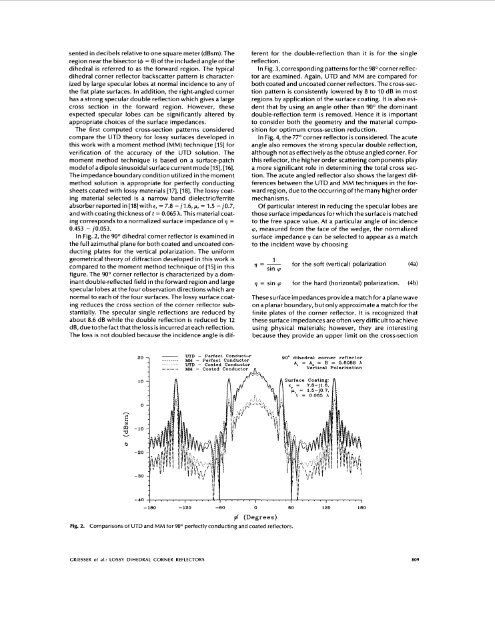
In Fig. 2, the 90° <strong>dihedral</strong> <strong>corner</strong> reflector is examined in<br />
the full azimuthal plane <strong>for</strong> both coated <strong>and</strong> uncoated con-<br />
ducting plates <strong>for</strong> the vertical polarization. The uni<strong>for</strong>m<br />
geometrical theory of diffraction developed in this work is<br />
compared to the moment method technique of [IS] in this<br />
figure. The 90° <strong>corner</strong> reflector is characterized by a dom-<br />
inant double-reflected field in the <strong>for</strong>ward region <strong>and</strong> large<br />
specular lobes at the four observation directions which are<br />
normal to each of the four surfaces. The <strong>lossy</strong> surface coat-<br />
ing reduces the cross section of the <strong>corner</strong> reflector sub-<br />
stantially. The specular single reflections are reduced by<br />
about 8.6 dB while the double reflection is reduced by 12<br />
d6,duetothefactthattheloss is incurred at each reflection.<br />
The loss is not doubled because the incidence angle is dif-<br />
v<br />
b<br />
UTD - Perfect ConductGr<br />
MU - Perfect<br />
UTD - Coated<br />
MU - Coated<br />
ferent <strong>for</strong> the double-reflection than it is <strong>for</strong> the single<br />
reflection.<br />
In Fig. 3, corresponding patterns <strong>for</strong>the98O <strong>corner</strong> reflec-<br />
tor are examined. Again, UTD <strong>and</strong> MM are compared <strong>for</strong><br />
both coated <strong>and</strong> uncoated <strong>corner</strong> reflectors. The cross-sec-<br />
tion pattern is consistently lowered by 8 to 10 dB in most<br />
regions by application of the surface coating. It is also evi-<br />
dent that by using an angle other than 90° the dominant<br />
double-reflection term is removed. Hence it is important<br />
to consider both the geometry <strong>and</strong> the material compo-<br />
sition <strong>for</strong> optimum cross-section <strong>reduction</strong>.<br />
In Fig. 4, the 77O <strong>corner</strong> reflector is considered. The acute<br />
angle also removes the strong specular double reflection,<br />
although not as effectively as the obtuse angled <strong>corner</strong>. For<br />
this reflector, the higher order scattering components play<br />
a more significant role in determining the total cross sec-<br />
tion. The acute angled reflector also shows the largest dif-<br />
ferences between the UTD <strong>and</strong> MM techniques in the <strong>for</strong>-<br />
ward region, due to the occurring of the many higher order<br />
mechanisms.<br />
Of particular interest in reducing the specular lobes are<br />
those surface impedances <strong>for</strong> which the surface is matched<br />
to the free space value. At a particular angle of incidence<br />
cp, measured from the face of the wedge, the normalized<br />
surface impedance 7 can be selected to appear as a match<br />
to the incident wave by choosing<br />
1<br />
7 = - <strong>for</strong> the soft (vertical) polarization (4a)<br />
sin cp<br />
7 = sin cp <strong>for</strong> the hard (horizontal) polarization. (4b)<br />
These surface impedances provide a match <strong>for</strong> a plane wave<br />
on a planar boundary, but onlyapproximate a match <strong>for</strong> the<br />
finite plates of the <strong>corner</strong> reflector. It is recognized that<br />
these surface impedancesare often verydifficult toachieve<br />
using physical materials; however, they are interesting<br />
because they provide an upper limit on the cross-section<br />
90' <strong>dihedral</strong> <strong>corner</strong> reflector<br />
A, = A, = B = 5.6088 X<br />
Vertical Polarlzation<br />
10 Surface Coating:<br />
0<br />
-10<br />
-20<br />
-30<br />
-40<br />
- 180 -120 -60 0 60 120 180<br />
6 (Degrees)<br />
Fig. 2. Comparisons of UTD <strong>and</strong> MM <strong>for</strong> 90° perfectly conducting <strong>and</strong> coated reflectors.<br />
CRIESSER et al.: LOSSY DIHEDRAL CORNER REFLECTORS 809


![Introduction to RF Stealth [Book Review] - Antennas and ...](https://img.yumpu.com/16857890/1/190x245/introduction-to-rf-stealth-book-review-antennas-and-.jpg?quality=85)