- Page 2: Fiber-Optic Communications
- Page 5 and 6: Published in France in 2007 by Herm
- Page 7 and 8: Table of Contents Foreword. .......
- Page 9 and 10: Table of Contents ix 2.5.1. Introdu
- Page 11 and 12: Table of Contents xi Chapter 5. Opt
- Page 13 and 14: Table of Contents xiii 8.2.4. Ampli
- Page 15 and 16: Table of Contents xv 11.2.2. Bendin
- Page 17 and 18: xviii Fiber-Optic Communications Pi
- Page 19 and 20: Overview Introduction Although the
- Page 21 and 22: Fields of use Introduction xxiii Th
- Page 23 and 24: Introduction xxv Chapter 7). Accord
- Page 25 and 26: Introduction xxvii Direct links bet
- Page 27 and 28: 2 Fiber-Optic Communications H y E
- Page 29 and 30: 4 Fiber-Optic Communications ∂k
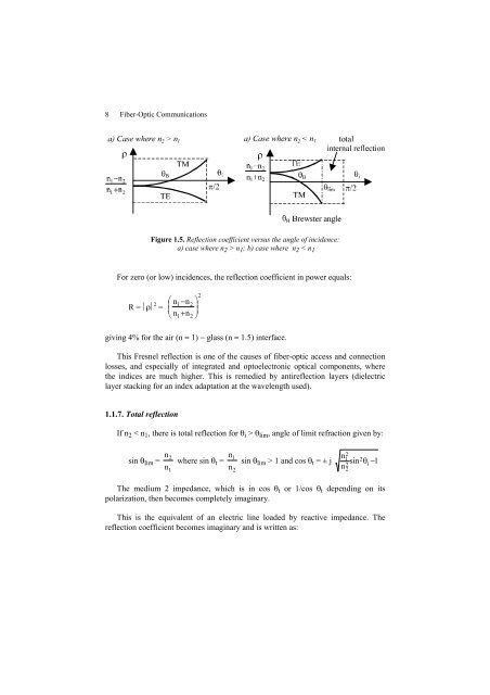
- Page 31: 6 Fiber-Optic Communications 1.1.5.
- Page 35 and 36: 10 Fiber-Optic Communications 1.2.
- Page 37 and 38: 12 Fiber-Optic Communications We mu
- Page 39 and 40: 14 Fiber-Optic Communications Figur
- Page 41 and 42: 16 Fiber-Optic Communications close
- Page 43 and 44: 18 Fiber-Optic Communications We ag
- Page 45 and 46: 20 Fiber-Optic Communications These
- Page 47 and 48: 22 Fiber-Optic Communications 1.4.4
- Page 49 and 50: 24 Fiber-Optic Communications τg (
- Page 51 and 52: 26 Fiber-Optic Communications Since
- Page 53 and 54: 28 Fiber-Optic Communications Trans
- Page 55 and 56: 30 Fiber-Optic Communications This
- Page 57 and 58: 32 Fiber-Optic Communications By de
- Page 59 and 60: 34 Fiber-Optic Communications ∆ E
- Page 61 and 62: 36 Fiber-Optic Communications a2 Hr
- Page 63 and 64: 38 Fiber-Optic Communications helic
- Page 65 and 66: 40 Fiber-Optic Communications 2.1.6
- Page 67 and 68: 42 Fiber-Optic Communications 2.2.
- Page 69 and 70: 44 Fiber-Optic Communications This
- Page 71 and 72: 46 Fiber-Optic Communications τg =
- Page 73 and 74: 48 Fiber-Optic Communications (disp
- Page 75 and 76: 50 Fiber-Optic Communications 40 20
- Page 77 and 78: 52 Fiber-Optic Communications - Lb
- Page 79 and 80: 54 Fiber-Optic Communications ∆τ
- Page 81 and 82: 56 Fiber-Optic Communications rays.
- Page 83 and 84:
58 Fiber-Optic Communications This
- Page 85 and 86:
60 Fiber-Optic Communications - γ
- Page 87 and 88:
62 Fiber-Optic Communications elect
- Page 89 and 90:
64 Fiber-Optic Communications In ph
- Page 91 and 92:
66 Fiber-Optic Communications - the
- Page 93 and 94:
Chapter 3 Fiber Optics Technology a
- Page 95 and 96:
Fiber Optics Technology and Impleme
- Page 97 and 98:
Fiber Optics Technology and Impleme
- Page 99 and 100:
Fiber Optics Technology and Impleme
- Page 101 and 102:
Fiber Optics Technology and Impleme
- Page 103 and 104:
porous deposit 3.2.4. Drawing Torch
- Page 105 and 106:
Fiber Optics Technology and Impleme
- Page 107 and 108:
Fiber Optics Technology and Impleme
- Page 109 and 110:
Fiber Optics Technology and Impleme
- Page 111 and 112:
Fiber Optics Technology and Impleme
- Page 113 and 114:
Fiber Optics Technology and Impleme
- Page 115 and 116:
A R (dB) 2 1 0 Fiber Optics Technol
- Page 117 and 118:
Fiber Optics Technology and Impleme
- Page 119 and 120:
Fiber Optics Technology and Impleme
- Page 121 and 122:
Fiber Optics Technology and Impleme
- Page 123 and 124:
Fiber Optics Technology and Impleme
- Page 125 and 126:
Fiber Optics Technology and Impleme
- Page 127 and 128:
104 Fiber-Optic Communications Type
- Page 129 and 130:
106 Fiber-Optic Communications c) i
- Page 131 and 132:
108 Fiber-Optic Communications 4.2.
- Page 133 and 134:
110 Fiber-Optic Communications 4.2.
- Page 135 and 136:
112 Fiber-Optic Communications A(z)
- Page 137 and 138:
114 Fiber-Optic Communications sin
- Page 139 and 140:
116 Fiber-Optic Communications 4.3.
- Page 141 and 142:
118 Fiber-Optic Communications 4.3.
- Page 143 and 144:
120 Fiber-Optic Communications Inpu
- Page 145 and 146:
122 Fiber-Optic Communications Tij
- Page 147 and 148:
124 Fiber-Optic Communications 5.1.
- Page 149 and 150:
126 Fiber-Optic Communications Ther
- Page 151 and 152:
128 Fiber-Optic Communications comp
- Page 153 and 154:
130 Fiber-Optic Communications - me
- Page 155 and 156:
132 Fiber-Optic Communications a: 2
- Page 157 and 158:
134 Fiber-Optic Communications ligh
- Page 159 and 160:
136 Fiber-Optic Communications swit
- Page 161 and 162:
138 Fiber-Optic Communications Micr
- Page 163 and 164:
140 Fiber-Optic Communications Figu
- Page 165 and 166:
142 Fiber-Optic Communications pair
- Page 167 and 168:
144 Fiber-Optic Communications 0.62
- Page 169 and 170:
146 Fiber-Optic Communications Φ0
- Page 171 and 172:
148 Fiber-Optic Communications more
- Page 173 and 174:
150 Fiber-Optic Communications Erbi
- Page 175 and 176:
152 Fiber-Optic Communications 6.2.
- Page 177 and 178:
154 Fiber-Optic Communications It i
- Page 179 and 180:
156 Fiber-Optic Communications Figu
- Page 181 and 182:
158 Fiber-Optic Communications - th
- Page 183 and 184:
160 Fiber-Optic Communications low
- Page 185 and 186:
162 Fiber-Optic Communications this
- Page 187 and 188:
164 Fiber-Optic Communications R V
- Page 189 and 190:
166 Fiber-Optic Communications Tabl
- Page 191 and 192:
168 Fiber-Optic Communications R V
- Page 193 and 194:
170 Fiber-Optic Communications brea
- Page 195 and 196:
172 Fiber-Optic Communications comp
- Page 197 and 198:
174 Fiber-Optic Communications Hete
- Page 199 and 200:
176 Fiber-Optic Communications This
- Page 201 and 202:
178 Fiber-Optic Communications C =
- Page 203 and 204:
180 Fiber-Optic Communications i S
- Page 205 and 206:
182 Fiber-Optic Communications 7.3.
- Page 207 and 208:
184 Fiber-Optic Communications This
- Page 209 and 210:
186 Fiber-Optic Communications subj
- Page 211 and 212:
188 Fiber-Optic Communications - x
- Page 213 and 214:
190 Fiber-Optic Communications 8.1.
- Page 215 and 216:
192 Fiber-Optic Communications emis
- Page 217 and 218:
194 Fiber-Optic Communications wher
- Page 219 and 220:
196 Fiber-Optic Communications negl
- Page 221 and 222:
198 Fiber-Optic Communications capa
- Page 223 and 224:
200 Fiber-Optic Communications resp
- Page 225 and 226:
202 Fiber-Optic Communications Erbi
- Page 227 and 228:
204 Fiber-Optic Communications wher
- Page 229 and 230:
206 Fiber-Optic Communications 9.1.
- Page 231 and 232:
208 Fiber-Optic Communications The
- Page 233 and 234:
210 Fiber-Optic Communications glob
- Page 235 and 236:
212 Fiber-Optic Communications PE 1
- Page 237 and 238:
214 Fiber-Optic Communications This
- Page 239 and 240:
216 Fiber-Optic Communications The
- Page 241 and 242:
218 Fiber-Optic Communications By a
- Page 243 and 244:
220 Fiber-Optic Communications a di
- Page 245 and 246:
222 Fiber-Optic Communications 9.3.
- Page 247 and 248:
224 Fiber-Optic Communications opti
- Page 249 and 250:
226 Fiber-Optic Communications 9.4.
- Page 251 and 252:
228 Fiber-Optic Communications Due
- Page 253 and 254:
230 Fiber-Optic Communications Proc
- Page 255 and 256:
10.1. Computer networks 10.1.1. Int
- Page 257 and 258:
Transmitter Star coupler Streaming
- Page 259 and 260:
Fiber-Optic Networks 237 10.1.4.2.
- Page 261 and 262:
Server Hub or switch 10.1.5. FDDI n
- Page 263 and 264:
Fiber-Optic Networks 241 multiple a
- Page 265 and 266:
Fiber-Optic Networks 243 prefers to
- Page 267 and 268:
10.2.3. Passive optical networks (P
- Page 269 and 270:
Fiber-Optic Networks 247 - GPON (Gi
- Page 271 and 272:
SDH name SONET name Number of chann
- Page 273 and 274:
Fiber-Optic Networks 251 This data
- Page 275 and 276:
Figure 10.10. Different types of op
- Page 277 and 278:
10.3.6. The optical OTN layer Fiber
- Page 279 and 280:
Fiber-Optic Networks 257 laser diod
- Page 281 and 282:
Access, LAN, external network … O
- Page 283 and 284:
Fiber-Optic Networks 261 quickly be
- Page 285 and 286:
264 Fiber-Optic Communications In a
- Page 287 and 288:
266 Fiber-Optic Communications 11.1
- Page 289 and 290:
268 Fiber-Optic Communications 11.2
- Page 291 and 292:
270 Fiber-Optic Communications Figu
- Page 293 and 294:
272 Fiber-Optic Communications Tran
- Page 295 and 296:
274 Fiber-Optic Communications Howe
- Page 297 and 298:
276 Fiber-Optic Communications The
- Page 299 and 300:
278 Fiber-Optic Communications Refl
- Page 301 and 302:
Exercises Part 1: fiber optics, pro
- Page 303 and 304:
- absolute index difference: n1 - n
- Page 305 and 306:
What is the maximum theoretical bit
- Page 307 and 308:
Exercise 2.2. Chromatic dispersion
- Page 309 and 310:
P R P = 10 kΩ +V i S R C = 5 kΩ
- Page 311 and 312:
Exercises 291 Which kilometer bandw
- Page 313 and 314:
- a receiver with noise equivalent
- Page 315 and 316:
Exercise 3.12. Very high bitrate si
- Page 317 and 318:
Characteristics of components Fiber
- Page 319 and 320:
Wavelength division multiplexers Ex
- Page 321 and 322:
302 Fiber-Optic Communications corr
- Page 323 and 324:
304 Fiber-Optic Communications We t
- Page 325 and 326:
306 Fiber-Optic Communications Exer
- Page 327 and 328:
308 Fiber-Optic Communications with
- Page 329 and 330:
310 Fiber-Optic Communications 600
- Page 331 and 332:
312 Fiber-Optic Communications Exer
- Page 333 and 334:
314 Fiber-Optic Communications - be
- Page 335 and 336:
316 Fiber-Optic Communications 14 d
- Page 337 and 338:
318 Fiber-Optic Communications Aver
- Page 339 and 340:
320 Fiber-Optic Communications Exer
- Page 341 and 342:
322 Fiber-Optic Communications the
- Page 343 and 344:
324 Fiber-Optic Communications and
- Page 345 and 346:
326 Fiber-Optic Communications Opti
- Page 347 and 348:
328 Fiber-Optic Communications Phot
- Page 349 and 350:
330 Fiber-Optic Communications disp
- Page 351 and 352:
332 Fiber-Optic Communications O op