B114-SciAutonics-Auburn Engineering - Darpa
B114-SciAutonics-Auburn Engineering - Darpa
B114-SciAutonics-Auburn Engineering - Darpa

Create successful ePaper yourself
Turn your PDF publications into a flip-book with our unique Google optimized e-Paper software.
The Autonomous Ground Vehicle RASCAL:<br />
Team <strong>SciAutonics</strong>/<strong>Auburn</strong> <strong>Engineering</strong> in<br />
the DARPA Grand Challenge 2005 *<br />
John Porter, Reinhold Behringer, Richard Elsley, Wayne Guthmiller, Gary Bostrup,<br />
Robert Addison, Jr., Kevin Knoedler, Monte Khoshnevisan, David Bevly, Robert Daily,<br />
William Travis, Wilfried Kubinger, Ron Dilley<br />
Corresponding Author: jporter@sciautonics.com<br />
<strong>SciAutonics</strong> LLC<br />
PO Box 1731<br />
Thousand Oaks, CA 91360-1731<br />
* DISCLAIMER: The information contained in this paper does not represent the official policies, either expressed<br />
or implied, of the Defense Advanced Research Projects Agency (DARPA) or the Department of Defense. DARPA<br />
does not guarantee the accuracy or reliability of the information in this paper.
Abstract<br />
RASCAL is the autonomous ground vehicle of the team <strong>SciAutonics</strong>/<strong>Auburn</strong>-<strong>Engineering</strong>. In the<br />
2004 DARPA Grand Challenge, it went 0.75 miles. For 2005, the team has improved the<br />
architecture and the software to allow faster operation, and better deal with obstacle detection.<br />
The vehicle uses closed-loop control using differential GPS and an inertial navigation system<br />
(INS) for navigation. Two Linux-based computers process sensing input from the GPS, INS,<br />
and other vehicle state sensors, along with LIDAR, ultrasound, and stereo vision sensors for real<br />
time obstacle avoidance. RASCAL can track waypoints at 25 mph and avoid collisions while<br />
driving at 16 mph.<br />
Introduction<br />
Our team was formed in March 2003, in response to the announcement of the DARPA Grand<br />
Challenge 2004. Initially it comprised a team of scientists and engineers from Rockwell<br />
Scientific (RSC) of Thousand Oaks, CA, although many volunteers from other companies have<br />
joined the team. 1 A limited liability company, <strong>SciAutonics</strong>, LLC, was created as the legal entity<br />
for ownership of the vehicle and accessories and for participation in the event. <strong>SciAutonics</strong> LLC<br />
currently has no paid employees but the company will own the team intellectual property and is<br />
positioned to transition into a company that will exploit its autonomous vehicle technology after<br />
the Grand Challenge series is complete. Our fundraising approach is to invite companies and<br />
individuals, including many of our volunteers, to invest in <strong>SciAutonics</strong> LLC. Key investors are<br />
Rockwell Scientific and ATV Corporation, ATV Corporation having provided our two ATV<br />
Prowler vehicles, RASCAL-1 (our Challenge vehicle) and RASCAL-2. Amgen, a Thousand<br />
Oaks based biotechnology company, has provided computing hardware for RASCAL and several<br />
Amgen employees are team members. Another key partner is the <strong>Engineering</strong> School of<br />
<strong>Auburn</strong> University who has developed the vehicle closed loop control system. For the Grand<br />
Challenge 2005, we reflect this close collaboration in our team name “<strong>SciAutonics</strong>/<strong>Auburn</strong>-<br />
1 Our volunteers are employed at numerous companies including Amgen and Teradyne in the Thousand Oaks area<br />
and a number of our volunteers are Rockwell Scientific retirees.
<strong>Engineering</strong>”. Finally, we have also teamed with ARC Seibersdorf who has provided their<br />
stereovision system for feature detection.<br />
Support for our mapping task and waypoint file creation comes from volunteers employed by<br />
Vestra, Inc, ESRI and the City of Thousand Oaks.<br />
RASCAL is designed to follow GPS waypoints while continuously sensing the terrain ahead and<br />
making real time corrections to the course in order to avoid driving off the road or colliding with<br />
obstacles. The vehicle control system (the control module) directs the vehicle by comparing the<br />
actual position (sensed by GPS or the IMU during GPS outages) to the desired position and<br />
minimizing the error by correcting the steer angle using a closed loop feedback control approach.<br />
In real time, while the vehicle is driving autonomously, a suite of sensors (LIDAR, stereovision,<br />
and ultrasound) is continuously sensing the terrain ahead of the vehicle. As objects are sensed<br />
(including road edges where possible, as well as static objects), the locations of undrivable areas<br />
are placed in a virtual map (that has real world coordinates) within the feature manager module.<br />
Data from this map are passed to the path planner module. The path planner then overlays the a<br />
priori route (based on the RDDF file) onto the object field map and recomputes a new pathway<br />
to avoid obstacles while staying within the allowed lateral offsets. Once an obstacle is avoided,<br />
the recomputed route reconverges with the a priori route. This recomputed path is then fed to the<br />
vehicle controller and the vehicle control system has RASCAL follow the recomputed path. The<br />
path planner will also limit speed predicated on the radii of curvature defined by the recomputed<br />
route.
Figure 1. Team <strong>SciAutonics</strong>/<strong>Auburn</strong>-<strong>Engineering</strong> (although a number of members could not be present.).<br />
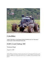
Vehicle<br />
The vehicle is based on a 2003 ATV Prowler, made by ATV Corporation (Orange, CA). It has a<br />
low center of gravity, it is rugged for off-road driving, it has four-wheel drive with an automatic<br />
continuously variable transmission (CVT), and a high-speed capability (55 mph driven by human<br />
driver on or off-road).<br />
Modifications have been made to the suspension system to accommodate the increased weight of<br />
computers and sensors. All vehicle changes made for autonomous operation have been made<br />
such that human driver operation is not precluded – the human-operation pedals (brake, throttle)<br />
are in place, and the driver can (with large force) override the steering servo.
Figure 2. RASCAL vehicle before customization and hardware installations (November 2003).<br />
Autonomous Operation<br />
The emphasis in designing our system architecture was on simplicity and modularity: failure of<br />
one component was not to affect the functionality of the main components. Therefore, our<br />
concept consists of independent modules that provide auxiliary information to the main driving<br />
module. At the core is the vehicle control actuation system, which controls steering, brake,<br />
throttle, and gear shift (automatic transmission, shifting between reverse, drive, and neutral).<br />
With the core system only operating, the vehicle can follow a given path of waypoints. If<br />
obstacles are detected to lie on that path, the behavior control computes a revised path that goes<br />
around the obstacle. The vehicle control module translates the deviation of measured location<br />
from the planned path and trajectory into a feedback control signal to the vehicle using<br />
proportional integral/differential (PID) control.
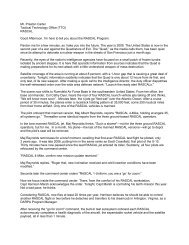
Lidar, Ultrasound, Stereovision<br />
Obstacle Detection Path tracking<br />
Feature Manager<br />
RF e-stop<br />
Figure 3. System Architecture.<br />
Processing<br />
RDDF - map<br />
Path Planner<br />
Vehicle Control System<br />
Steering<br />
brake throttle Shift<br />
Vehicle<br />
We use two 750 MHz Pentium-4 embedded systems built as a PC104+ stack. These two<br />
computers do not require active cooling. They perform all the key functions for autonomous<br />
driving such as sensor input and processing (from serial ports), path recomputation (for collision<br />
avoidance and waypoint following) and vehicle control output. The software is modular.<br />
Information is passed between modules using UDP. Data acquisition modules interface to<br />
sensors via RS232 or RS422. Sensor processor modules process sensor data to determine<br />
vehicle state (current position, heading, and velocity) and to detect obstacles. The path planner<br />
module alters the planned path as necessary to avoid obstacles. The vehicle control module takes<br />
current vehicle state and the planned path as inputs and adjusts throttle, brake, steering, and gear<br />
as necessary to keep the vehicle on course. In addition we have simulation modules that allow<br />
for testing of all other modules, with the exception of the data acquisition modules.<br />
GPS, Compass<br />
Odometer, INS
Vehicle Power<br />
Source of Power<br />
The locomotion power source is from a 660 cc 4-cycle carbureted internal combustion engine<br />
built by Yamaha. The maximum power consumption for the drive train is approximately 35<br />
horsepower or approximately 26 kW. Two portable power generators (Honda Model EU2000i)<br />
mounted on the vehicle supply electrical power (4 kW) for computers, sensors, and actuators. A<br />
total of 32 gallons of unleaded gasoline supplies the fuel for the vehicle and all the equipment.<br />
Safety Equipment on-board the Challenge Vehicle<br />
Fuel Containment<br />
Fuel is contained in two foam-lined fuel cells protected by a roll cage.<br />
Fire Suppression<br />
A fire extinguisher has been mounted externally on the vehicle in an obvious easily reached open<br />
location.<br />
Audio and Visual Warning Devices<br />
A mounted beeping alarm and flashing strobe provide audible and visual warnings as specified<br />
by GC rules.<br />
Autonomous Servicing<br />
Refueling<br />
The vehicle will carry sufficient gasoline to complete the entire race<br />
Additional servicing activities<br />
The vehicle will not be autonomously serviced.
Vehicle Performance and Specifications<br />
Top Speed of Vehicle<br />
The top speed of the vehicle is 55 MPH in 4-wheel drive.<br />
Maximum Range of Vehicle<br />
The maximum range of the vehicle under race conditions with full tanks is approximately 300<br />
miles.<br />
Hazardous devices<br />
Other than the vehicle itself and the fuel onboard, there are no hazardous devices. The<br />
generators produce 120VAC, protected by common wiring insulation and using conventional<br />
outlets.<br />
Tire Properties<br />
The vehicle is based on an ATV style vehicle with large floatation tires. The tires have a chevron<br />
style tread pattern that is raised 0.75 inches. On hard surfaces where just the treads are touching,<br />
the ground pressure can be as high as 29 pounds per square inch. However, on softer soil where<br />
more of the tire surface is touching the ground, the ground pressure is reduced to approximately<br />
5 pounds per square inch. The impact to the environment should be no greater than if a standard<br />
4 wheel drive ATV were driving on the path.<br />
Maximum physical dimensions<br />
The overall vehicle length is 105 inches with a maximum width of 60 inches. The maximum<br />
height excluding the DARPA provided E-Stop antenna reaches 65 inches; including the antenna<br />
adds an additional 26 inches. The vehicle (excluding the human driver, but with computer<br />
systems installed) weighs appoximately1500 pounds.<br />
Localization<br />
The very first step after obtaining the DARPA RDDF file is to improve the given route based on<br />
existing map data. Such data exists in the form of published maps and has been acquired by<br />
predriving certain roads prior to the course area being placed off limits. For the Grand Challenge<br />
Event, during the two hours between obtaining the RDDF file and the actual vehicle start, a<br />
reference path is computed which includes the DARPA waypoints, but also creates a more
efined path at a higher resolution. This reference path is the basis for the vehicle following the<br />
given route.<br />
The primary sensor used in estimating vehicle state is a Navcom Starfire GPS system that<br />
provides differential location updates at 5Hz rate. A Rockwell Collins GNP-10 provides inertial<br />
updates of acceleration and angular rate at 50 Hz through accelerometers and gyros. A TCM2<br />
magnetometer provides roll, pitch, and yaw data at 16 Hz. A speedometer encoder provides<br />
speed data at a variable rate, depending on the speed of the vehicle. A Kalman filter fuses these<br />
data streams into an estimate of the actual location, heading, and velocity. Depending on whether<br />
GPS data are available at all or if they are obtained in differential or normal mode, a different set<br />
of error covariance elements is used for the estimation process. Position, speed, and heading can<br />
be derived from the GPS system alone. However, use of the Kalman filter to merge the GPS<br />
location data with the other sources of vehicle state data allows the system to be driven during an<br />
outage of GPS or differential GPS.<br />
Sensing<br />
The main obstacle sensing is based on SICK LIDAR sensors. Two of these sensors are used to<br />
scan horizontally, to detect objects that are in the path to be driven. Two other LIDAR sensors<br />
scan vertically, to detect surface continuity and discontinuity (negative obstacles). The maximum<br />
look-ahead distance of these sensors is 80 m.<br />
Other sensors include a suite of ultrasound sensors, which are mounted to obtain close-range<br />
distance measurement of nearby objects. These are used to allow driving in reverse and to<br />
navigate between tight walls. The LIDAR sensors cover this case as well, but the ultrasound<br />
sensors act as additional redundant sensors, which are less susceptible to dust or fog.<br />
As a mid-range (10 m < R
quantization of 8 bits/pixel. The cameras are connected by a 400MBit-FireWire network to an<br />
Embedded Vision System. That system is based on a Texas Instruments TMS320C6414 DSP<br />
running at 1GHz and the operating system is DSP/BIOS II from Texas Instruments. The<br />
embedded system is responsible for the synchronous acquisition of both images, for execution of<br />
the computer vision algorithms, and the communication with the RASCAL feature manager via<br />
an Ethernet interface using UDP sockets. The whole stereovision sensor is protected against dust<br />
and sunlight by a special housing.<br />
The main task of the stereovision sensor is the detection of obstacles and lane limitations in front<br />
of RASCAL. For obstacle detection, a stereo matching method is used. For lane limitation<br />
detection, left and right camera images are divided into different regions-of-interest (ROI’s).<br />
Each ROI is median-filtered and afterwards, a linear gradient filter is used to extract edges. By<br />
applying the Hough transformation, line segments are identified in each ROI and grouped<br />
together over the whole image to form left and right lane limitation. Lanes are split into<br />
fragments, which are by themselves marked as obstacles. With this approach, the integration of<br />
this sensor’s output into the RASCAL feature manager is straight forward, since all sensor<br />
systems use equivalent obstacle representation.<br />
The output of all the sensing systems is fed into a 2D birds-eye view representation of a global<br />
map coordinate system within the feature manager. A coordinate transformation provides a<br />
common coordinate system in UTM coordinates. Each detected object (from any sensor) is<br />
virtually plotted into this map framework. Using an R-tree, the system is able to decide if the<br />
planned path intersects with an obstacle. If an object is deemed to lie on the vehicle path, an<br />
alternative path is computed, avoiding a collision with the obstacle.<br />
Vehicle Control<br />
The vehicle control module accepts a series of waypoints as well as vehicle state information as<br />
its input. Inasmuch as the path planner has recomputed the course to avoid any sensed obstacles<br />
and to ensure lateral offsets are not violated, the control module itself is only concerned with<br />
accurate waypoint following. Its goal is to keep the vehicle location on the planned path and its
trajectory aligned with the waypoint trajectory. Once a waypoint is passed, the system continues<br />
to the next waypoint.<br />
If the vehicle becomes stuck, the controller will increase the control output to overcome the force<br />
holding the vehicle back. In the future, strategies will be added for specific maneuvers, in<br />
response to specific reasons for vehicle being stuck. The vehicle speed in sharp curves is<br />
limited, to limit lateral g-forces dependent on the curve’s radius, to an actual speed, which would<br />
be less than the RDDF file allowed maximum speed.<br />
When a human driver drives the vehicle, all the usual controls are accessible to the driver. The<br />
vehicle actuators are powered off for the manual override mode.<br />
System Tests<br />
In the lab environment, we use the GAZEBO toolkit to perform system and vehicle simulations.<br />
For outdoor testing, our team has permission to perform autonomous vehicle testing at a future<br />
public park site owned by the Conejo Recreation and Park District, the park district for the City<br />
of Thousand Oaks.<br />
Also, a number of public off-road sites in the Mojave Desert have been used to test the stability<br />
and endurance of our system. These sites selected were all outside the exclusion zone identified<br />
by DARPA for Challenge vehicles.<br />
Summary<br />
The all-volunteer <strong>SciAutonics</strong> / <strong>Auburn</strong> <strong>Engineering</strong> team, using the resources of its member<br />
owned company, <strong>SciAutonics</strong> LLC, including help from corporate investors, has built RASCAL<br />
specifically to compete in the DARPA Grand Challenge. A suite of sensors identifies obstacles<br />
to avoid, and the locations of such obstacles are recorded in the vehicles feature manager. The<br />
vehicle path is then defined by a waypoint sequence that is prepared in real time by the vehicle’s<br />
science-based path planner that takes as its input the provided RDDF file information along with
the output of the feature manager. The vehicle control system then uses a PID closed loop<br />
control to follow the waypoint sequence output from the path planner at speeds up to 16 mph.