CS 3000/4000/4080HZ Manual (pdf) - Loyola Enterprises Inc. Audio ...
CS 3000/4000/4080HZ Manual (pdf) - Loyola Enterprises Inc. Audio ...
CS 3000/4000/4080HZ Manual (pdf) - Loyola Enterprises Inc. Audio ...

You also want an ePaper? Increase the reach of your titles
YUMPU automatically turns print PDFs into web optimized ePapers that Google loves.
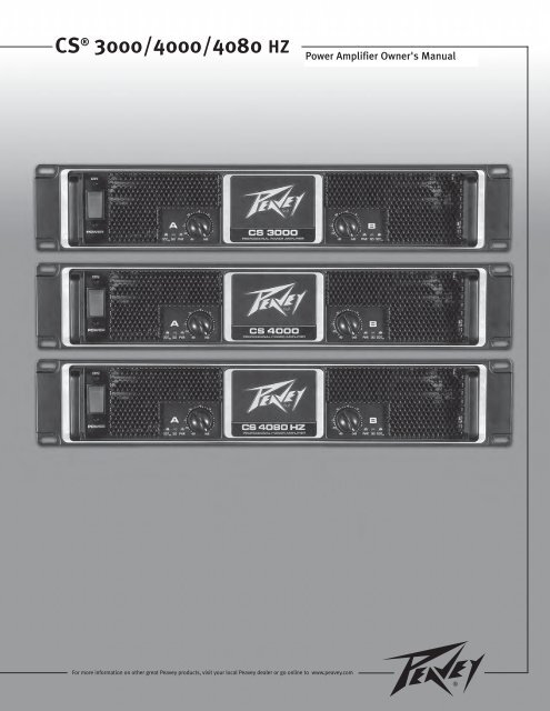
<strong>CS</strong> ® <strong>3000</strong>/<strong>4000</strong>/4080 HZ<br />
For more information on other great Peavey products, visit your local Peavey dealer or go online to www.peavey.com<br />
Power Amplifier Owner's <strong>Manual</strong>
Intended to alert the user to the presence of uninsulated “dangerous voltage” within the product’s<br />
enclosure that may be of sufficient magnitude to constitute a risk of electric shock to persons.<br />
Intended to alert the user of the presence of important operating and maintenance (servicing)<br />
instructions in the literature accompanying the product.<br />
CAUTION: Risk of electrical shock — DO NOT OPEN!<br />
CAUTION: To reduce the risk of electric shock, do not remove cover. No user serviceable parts inside.<br />
Refer servicing to qualified service personnel.<br />
WARNING: To prevent electrical shock or fire hazard, this apparatus should not be exposed to rain or<br />
moisture‚ and objects filled with liquids‚ such as vases‚ should not be placed on this apparatus. Before<br />
using this apparatus‚ read the operating guide for further warnings.<br />
Este símbolo tiene el propósito, de alertar al usuario de la presencia de “(voltaje) peligroso” sin<br />
aislamiento dentro de la caja del producto y que puede tener una magnitud suficiente como para<br />
constituir riesgo de descarga eléctrica.<br />
Este símbolo tiene el propósito de alertar al usario de la presencia de instruccones importantes sobre la<br />
operación y mantenimiento en la información que viene con el producto.<br />
PRECAUCION: Riesgo de descarga eléctrica ¡NO ABRIR!<br />
PRECAUCION: Para disminuír el riesgo de descarga eléctrica, no abra la cubierta. No hay piezas útiles<br />
dentro. Deje todo mantenimiento en manos del personal técnico cualificado.<br />
ADVERTENCIA: Para prevenir choque electrico o riesgo de incendios, este aparato no se debe exponer a<br />
la lluvia o a la humedad. Los objetos llenos de liquidos, como los floreros, no se deben colocar encima<br />
de este aparato. Antes de usar este aparato, lea la guia de funcionamiento para otras advertencias.<br />
Ce symbole est utilisé dans ce manuel pour indiquer à l’utilisateur la présence d’une tension dangereuse<br />
pouvant être d’amplitude suffisante pour constituer un risque de choc électrique.<br />
Ce symbole est utilisé dans ce manuel pour indiquer à l’utilisateur qu’il ou qu’elle trouvera d’importantes<br />
instructions concernant l’utilisation et l’entretien de l’appareil dans le paragraphe signalé.<br />
ATTENTION: Risques de choc électrique — NE PAS OUVRIR!<br />
ATTENTION: Afin de réduire le risque de choc électrique, ne pas enlever le couvercle. Il ne se trouve<br />
à l’intérieur aucune pièce pouvant être reparée par l’utilisateur. Confiez I’entretien et la réparation de<br />
l’appareil à un réparateur Peavey agréé.<br />
AVIS: Dans le but de reduire les risques d’incendie ou de decharge electrique, cet appareil ne doit<br />
pas etre expose a la pluie ou a l’humidite et aucun objet rempli de liquide, tel qu’un vase, ne doit<br />
etre pose sur celui-ci. Avant d’utiliser de cet appareil, lisez attentivement le guide fonctionnant pour<br />
avertissements supplémentaires.<br />
Dieses Symbol soll den Anwender vor unisolierten gefährlichen Spannungen innerhalb des Gehäuses<br />
warnen, die von Ausreichender Stärke sind, um einen elektrischen Schlag verursachen zu können.<br />
Dieses Symbol soll den Benutzer auf wichtige Instruktionen in der Bedienungsanleitung aufmerksam<br />
machen, die Handhabung und Wartung des Produkts betreffen.<br />
VORSICHT: Risiko — Elektrischer Schlag! Nicht öffnen!<br />
VORSICHT: Um das Risiko eines elektrischen Schlages zu vermeiden, nicht die Abdeckung enfernen.<br />
Es befinden sich keine Teile darin, die vom Anwender repariert werden könnten. Reparaturen nur von<br />
qualifiziertem Fachpersonal durchführen lassen.<br />
WARNUNG: Um elektrischen Schlag oder Brandgefahr zu verhindern, sollte dieser Apparat nicht<br />
Regen oder Feuchtigkeit ausgesetzt werden und Gegenstände mit Flüssigkeiten gefuellt, wie Vasen,<br />
nicht auf diesen Apparat gesetzt werden. Bevor dieser Apparat verwendet wird, lesen Sie bitte den<br />
Funktionsführer für weitere Warnungen.<br />
2
IMPORTANT SAFETY INSTRUCTIONS<br />
WARNING: When using electrical products, basic cautions should always be followed, including the following:<br />
1. Read these instructions.<br />
2. Keep these instructions.<br />
3. Heed all warnings.<br />
4. Follow all instructions.<br />
5. Do not use this apparatus near water.<br />
6. Clean only with a dry cloth.<br />
7. Do not block any of the ventilation openings. Install in accordance with manufacturer’s instructions.<br />
8. Do not install near any heat sources such as radiators, heat registers, stoves or other apparatus (including amplifiers)<br />
that produce heat.<br />
9. Do not defeat the safety purpose of the polarized or grounding-type plug. A polarized plug has two blades with one<br />
wider than the other. A grounding type plug has two blades and a third grounding plug. The wide blade or third prong is<br />
provided for your safety. If the provided plug does not fit into your outlet, consult an electrician for replacement of the<br />
obsolete outlet.<br />
10. Protect the power cord from being walked on or pinched, particularly at plugs, convenience receptacles, and the point<br />
they exit from the apparatus.<br />
11. Only use attachments/accessories provided by the manufacturer.<br />
12. Use only with a cart, stand, tripod, bracket, or table specified by the manufacturer, or sold with the apparatus. When a<br />
cart is used, use caution when moving the cart/apparatus combination to avoid injury from tip-over.<br />
13. Unplug this apparatus during lightning storms or when unused for long periods of time.<br />
14. Refer all servicing to qualified service personnel. Servicing is required when the apparatus has been damaged in any<br />
way, such as power-supply cord or plug is damaged, liquid has been spilled or objects have fallen into the apparatus,<br />
the apparatus has been exposed to rain or moisture, does not operate normally, or has been dropped.<br />
15. Never break off the ground pin. Write for our free booklet “Shock Hazard and Grounding.” Connect only to a power<br />
supply of the type marked on the unit adjacent to the power supply cord.<br />
16. If this product is to be mounted in an equipment rack, rear support should be provided.<br />
17. Note for UK only: If the colors of the wires in the mains lead of this unit do not correspond with the terminals in your<br />
plug‚ proceed as follows:<br />
a) The wire that is colored green and yellow must be connected to the terminal that is marked by the letter E‚ the earth<br />
symbol‚ colored green or colored green and yellow.<br />
b) The wire that is colored blue must be connected to the terminal that is marked with the letter N or the color black.<br />
c) The wire that is colored brown must be connected to the terminal that is marked with the letter L or the color red.<br />
18. This electrical apparatus should not be exposed to dripping or splashing and care should be taken not to place objects<br />
containing liquids, such as vases, upon the apparatus.<br />
19. Exposure to extremely high noise levels may cause a permanent hearing loss. Individuals vary considerably in susceptibility<br />
to noise-induced hearing loss, but nearly everyone will lose some hearing if exposed to sufficiently intense noise<br />
for a sufficient time. The U.S. Government’s Occupational Safety and Health Administration (OSHA) has specified the<br />
following permissible noise level exposures:<br />
Duration Per Day In Hours Sound Level dBA, Slow Response<br />
8 90<br />
6 92<br />
4 95<br />
3 97<br />
2 100<br />
1 1⁄2 102<br />
1 105<br />
1⁄2 110<br />
1⁄4 or less 115<br />
According to OSHA, any exposure in excess of the above permissible limits could result in some hearing loss. Ear plugs or protectors to<br />
the ear canals or over the ears must be worn when operating this amplification system in order to prevent a permanent hearing loss, if<br />
exposure is in excess of the limits as set forth above. To ensure against potentially dangerous exposure to high sound pressure levels, it is<br />
recommended that all persons exposed to equipment capable of producing high sound pressure levels such as this amplification system be<br />
protected by hearing protectors while this unit is in operation.<br />
SAVE THESE INSTRUCTIONS!<br />
3
WICHTIGE SICHERHEITSHINWEISE<br />
ACHTUNG: Beim Einsatz von Elektrogeräten müssen u.a. grundlegende Vorsichtsmaßnahmen befolgt werden:<br />
1. Lesen Sie sich diese Anweisungen durch.<br />
2. Bewahren Sie diese Anweisungen auf.<br />
3. Beachten Sie alle Warnungen.<br />
4. Befolgen Sie alle Anweisungen.<br />
5. Setzen Sie dieses Gerät nicht in der Nähe von Wasser ein.<br />
6. Reinigen Sie es nur mit einem trockenen Tuch.<br />
7. Blockieren Sie keine der Lüftungsöffnungen. Führen Sie die Installation gemäß den Anweisungen des Herstellers durch.<br />
8. Installieren Sie das Gerät nicht neben Wärmequellen wie Heizungen, Heizgeräten, Öfen oder anderen Geräten (auch Verstärkern),<br />
die Wärme erzeugen.<br />
9. Beeinträchtigen Sie nicht die Sicherheitswirkung des gepolten Steckers bzw. des Erdungssteckers. Ein gepolter Stecker weist<br />
zwei Stifte auf, von denen einer breiter ist als der andere. Ein Erdungsstecker weist zwei Stifte und einen dritten Erdungsstift auf.<br />
Der breite Stift bzw. der dritte Stift dient Ihrer Sicherheit. Sollte der beiliegende Stecker nicht in Ihre Steckdose passen, wenden<br />
Sie sich bitte an einen Elektriker, um die ungeeignete Steckdose austauschen zu lassen.<br />
10. Schützen Sie das Netzkabel, sodass niemand darauf tritt oder es geknickt wird, insbesondere an Steckern oder Buchsen und<br />
ihren Austrittsstellen aus dem Gerät.<br />
11. Verwenden Sie nur die vom Hersteller erhältlichen Zubehörgeräte oder Zubehörteile.<br />
12. Verwenden Sie nur einen Wagen, Stativ, Dreifuß, Träger oder Tisch, der den Angaben des Herstellers entspricht oder zusammen<br />
mit dem Gerät verkauft wurde. Wird ein Wagen verwendet, bewegen Sie den Wagen mit dem darauf befindlichen Gerät besonders<br />
vorsichtig, damit er nicht umkippt und möglicherweise jemand verletzt wird.<br />
13. Trennen Sie das Gerät während eines Gewitters oder während längerer Zeiträume, in denen es nicht benutzt wird, von der<br />
Stromversorgung.<br />
14. Lassen Sie sämtliche Wartungsarbeiten von qualifizierten Kundendiensttechnikern durchführen. Eine Wartung ist erforderlich,<br />
wenn das Gerät in irgendeiner Art beschädigt wurde, etwa wenn das Netzkabel oder der Netzstecker beschädigt wurden,<br />
Flüssigkeit oder Gegenstände in das Gerät gelangt sind, das Gerät Regen oder Feuchtigkeit ausgesetzt wurde, nicht normal<br />
arbeitet oder heruntergefallen ist.<br />
15. Der Erdungsstift darf nie entfernt werden. Auf Wunsch senden wir Ihnen gerne unsere kostenlose Broschüre „Shock Hazard and<br />
Grounding“ (Gefahr durch elektrischen Schlag und Erdung) zu. Schließen Sie nur an die Stromversorgung der Art an, die am<br />
Gerät neben dem Netzkabel angegeben ist.<br />
16. Wenn dieses Produkt in ein Geräte-Rack eingebaut werden soll, muss eine Versorgung über die Rückseite eingerichtet werden.<br />
17. Hinweis – Nur für Großbritannien: Sollte die Farbe der Drähte in der Netzleitung dieses Geräts nicht mit den Klemmen in Ihrem<br />
Stecker übereinstimmen, gehen Sie folgendermaßen vor:<br />
a) Der grün-gelbe Draht muss an die mit E (Symbol für Erde) markierte bzw. grüne oder grün-gelbe Klemme angeschlossen<br />
werden.<br />
b) Der blaue Draht muss an die mit N markierte bzw. schwarze Klemme angeschlossen werden.<br />
c) Der braune Draht muss an die mit L markierte bzw. rote Klemme angeschlossen werden.<br />
18. Dieses Gerät darf nicht ungeschützt Wassertropfen und Wasserspritzern ausgesetzt werden und es muss darauf geachtet<br />
werden, dass keine mit Flüssigkeiten gefüllte Gegenstände, wie z. B. Blumenvasen, auf dem Gerät abgestellt werden.<br />
19. Belastung durch extrem hohe Lärmpegel kann zu dauerhaftem Gehörverlust führen. Die Anfälligkeit für durch Lärm bedingten<br />
Gehörverlust ist von Mensch zu Mensch verschieden, das Gehör wird jedoch bei jedem in gewissem Maße geschädigt, der über<br />
einen bestimmten Zeitraum ausreichend starkem Lärm ausgesetzt ist. Die US-Arbeitsschutzbehörde (Occupational and Health<br />
Administration, OSHA) hat die folgenden zulässigen Pegel für Lärmbelastung festgelegt:<br />
Dauer pro Tag in Stunden Geräuschpegel dBA, langsame Reaktion<br />
8 90<br />
6 92<br />
4 95<br />
3 97<br />
2 100<br />
1 1 ⁄2 102<br />
1 105<br />
1 ⁄2 110<br />
1 ⁄4 oder weniger 115<br />
Laut OSHA kann jede Belastung über den obenstehenden zulässigen Grenzwerten zu einem gewissen Gehörverlust führen. Sollte<br />
die Belastung die obenstehenden Grenzwerte übersteigen, müssen beim Betrieb dieses Verstärkungssystems Ohrenstopfen oder<br />
Schutzvorrichtungen im Gehörgang oder über den Ohren getragen werden, um einen dauerhaften Gehörverlust zu verhindern. Um sich vor<br />
einer möglicherweise gefährlichen Belastung durch hohe Schalldruckpegel zu schützen, wird allen Personen empfohlen, die mit Geräten<br />
arbeiten, die wie dieses Verstärkungssystem hohe Schalldruckpegel erzeugen können, beim Betrieb dieses Geräts einen Gehörschutz zu tragen.<br />
BEWAHREN SIE DIESE SICHERHEITSHINWEISE AUF!<br />
4
INSTRUCTIONS IMPORTANTES DE SECURITE<br />
ATTENTION: L’utilisation de tout appareil électrique doit être soumise aux precautions d’usage incluant:<br />
1. Lire ces instructions.<br />
2. Gardez ce manuel pour de futures références.<br />
3. Prétez attention aux messages de précautions de ce manuel.<br />
4. Suivez ces instructions.<br />
5. N’utilisez pas cette unité proche de plans d’eau.<br />
6. N’utilisez qu’un tissu sec pour le nettoyage de votre unité.<br />
7. N’obstruez pas les systèmes de refroidissement de votre unité et installez votre unité en fonction des instructions<br />
de ce manuel.<br />
8. Ne positionnez pas votre unité à proximité de toute source de chaleur.<br />
9. Connectez toujours votre unité sur une alimentation munie de prise de terre utilisant le cordon d’alimentation<br />
fourni.<br />
10. Protégez les connecteurs de votre unité et positionnez les cablages pour éviter toutes déconnexions accidentelles.<br />
11. N’utilisez que des fixations approuvées par le fabriquant.<br />
12. Lors de l’utilsation sur pied ou pole de support, assurez dans le cas de déplacement de l’ensemble enceinte/<br />
support de prévenir tout basculement intempestif de celui-ci.<br />
13. Il est conseillé de déconnecter du secteur votre unité en cas d’orage ou de durée prolongée sans utilisation.<br />
14. Seul un technicien agréé par le fabriquant est à même de réparer/contrôler votre unité. Celle-ci doit être contrôlée si<br />
elle a subit des dommages de manipulation, d’utilisation ou de stockage (humidité,…).<br />
15. Ne déconnectez jamais la prise de terre de votre unité.<br />
16. Si votre unité est destinée a etre montée en rack, des supports arriere doivent etre utilises.<br />
17. Note pour les Royaumes-Unis: Si les couleurs de connecteurs du cable d’alimentation ne correspond pas au guide<br />
de la prise secteur, procédez comme suit:<br />
a) Le connecteur vert et jaune doit être connectrer au terminal noté E, indiquant la prise de terre ou correspondant<br />
aux couleurs verte ou verte et jaune du guide.<br />
b) Le connecteur Bleu doit être connectrer au terminal noté N, correspondnat à la couleur noire du guide.<br />
c) Le connecteur marron doit être connectrer au terminal noté L, correspondant à la couleur rouge du guide.<br />
18. Cet équipement électrique ne doit en aucun cas être en contact avec un quelconque liquide et aucun objet<br />
contenant un liquide, vase ou autre ne devrait être posé sur celui-ci.<br />
19. Une exposition à de hauts niveaux sonores peut conduire à des dommages de l’écoute irréversibles. La susceptibilité<br />
au bruit varie considérablement d’un individu à l’autre, mais une large majorité de la population expériencera<br />
une perte de l’écoute après une exposition à une forte puissance sonore pour une durée prolongée. L’organisme de<br />
la santé américaine (OSHA) a produit le guide ci-dessous en rapport à la perte occasionnée:<br />
Durée par Jour (heures) Niveau sonore moyen (dBA)<br />
8 90<br />
6 92<br />
4 95<br />
3 97<br />
2 100<br />
1 1 ⁄2 102<br />
1 105<br />
1 ⁄2 110<br />
1 ⁄4 ou inférieur 115<br />
D’après les études menées par le OSHA, toute exposition au delà des limites décrites ce-dessus entrainera des pertes de l’écoute chez la<br />
plupart des sujets. Le port de système de protection (casque, oreilette de filtrage,…) doit être observé lors de l’opération cette unité ou des<br />
dommages irréversibles peuvent être occasionnés. Le port de ces systèmes doit être observé par toutes personnes susceptibles d’être exposées<br />
à des conditions au delà des limites décrites ci-dessus.<br />
GARDEZ CES INSTRUCTIONS!<br />
5
INSTRUCCIONES IMPORTANTES PARA SU SEGURIDAD<br />
CUIDADO: Cuando use productos electrónicos, debe tomar precauciones básicas, incluyendo las siguientes:<br />
1. Lea estas instrucciones.<br />
2. Guarde estas instrucciones.<br />
3. Haga caso de todos los consejos.<br />
4. Siga todas las instrucciones.<br />
5. No usar este aparato cerca del agua.<br />
6. Limpiar solamente con una tela seca.<br />
7. No bloquear ninguna de las salidas de ventilación. Instalar de acuerdo a las instrucciones del fabricante.<br />
8. No instalar cerca de ninguna fuente de calor como radiadores, estufas, hornos u otros aparatos (incluyendo amplificadores)<br />
que produzcan calor.<br />
9. No retire la patilla protectora del enchufe polarizado o de tipo “a Tierra”. Un enchufe polarizado tiene dos puntas, una de<br />
ellas más ancha que la otra. Un enchufe de tipo “a Tierra” tiene dos puntas y una tercera “a Tierra”. La punta ancha (la<br />
tercera ) se proporciona para su seguridad. Si el enchufe proporcionado no encaja en su enchufe de red, consulte a un<br />
electricista para que reemplaze su enchufe obsoleto.<br />
10. Proteja el cable de alimentación para que no sea pisado o pinchado, particularmente en los enchufes, huecos, y los puntos<br />
que salen del aparato.<br />
11. Usar solamente añadidos/accesorios proporcionados por el fabricante.<br />
12. Usar solamente un carro, pie, trípode, o soporte especificado por el fabricante, o vendido junto al aparato. Cuando se use<br />
un carro, tenga cuidado al mover el conjunto carro/aparato para evitar que se dañe en un vuelco. No suspenda esta caja de<br />
ninguna manera.<br />
13. Desenchufe este aparato durante tormentas o cuando no sea usado durante largos periodos de tiempo.<br />
14. Para cualquier reparación, acuda a personal de servicio cualificado. Se requieren reparaciones cuando el aparato ha sido<br />
dañado de alguna manera, como cuando el cable de alimentación o el enchufe se han dañado, algún líquido ha sido<br />
derramado o algún objeto ha caído dentro del aparato, el aparato ha sido expuesto a la lluvia o la humedad, no funciona de<br />
manera normal, o ha sufrido una caída.<br />
15. Nunca retire la patilla de Tierra.Escríbanos para obtener nuestro folleto gratuito “Shock Hazard and Grounding” (“Peligro<br />
de Electrocución y Toma a Tierra”). Conecte el aparato sólo a una fuente de alimentación del tipo marcado al lado del cable<br />
de alimentación.<br />
16. Si este producto va a ser enracado con más equipo, use algún tipo de apoyo trasero.<br />
17. Nota para el Reino Unido solamente: Si los colores de los cables en el enchufe principal de esta unidad no corresponden<br />
con los terminales en su enchufe‚ proceda de la siguiente manera:<br />
a) El cable de color verde y azul debe ser conectado al terminal que está marcado con la letra E‚ el símbolo de Tierra<br />
(earth)‚ coloreado en verde o en verde y amarillo.<br />
b) El cable coloreado en azul debe ser conectado al terminal que está marcado con la letra N o el color negro.<br />
c) El cable coloreado en marrón debe ser conectado al terminal que está marcado con la letra L o el color rojo.<br />
18. Este aparato eléctrico no debe ser sometido a ningún tipo de goteo o salpicadura y se debe tener cuidado para no poner<br />
objetos que contengan líquidos, como vasos, sobre el aparato.<br />
19. La exposición a altos niveles de ruido puede causar una pérdida permanente en la audición. La susceptibilidad a la pérdida<br />
de audición provocada por el ruido varía según la persona, pero casi todo el mundo perderá algo de audición si se expone<br />
a un nivel de ruido suficientemante intenso durante un tiempo determinado. El Departamento para la Salud y para la<br />
Seguridad del Gobierno de los Estados Unidos (OSHA) ha especificado las siguientes exposiciones al ruido permisibles:<br />
Duración por Día en Horas Nivel de Sonido dBA, Respuesta Lenta<br />
8 90<br />
6 92<br />
4 95<br />
3 97<br />
2 100<br />
1 1 ⁄2 102<br />
1 105<br />
1 ⁄2 110<br />
1 ⁄4 o menos 115<br />
De acuerdo al OSHA, cualquier exposición que exceda los límites arriba indicados puede producir algún tipo de pérdida en la audición.<br />
Protectores para los canales auditivos o tapones para los oídos deben ser usados cuando se opere con este sistema de sonido para prevenir<br />
una pérdida permanente en la audición, si la exposición excede los límites indicados más arriba. Para protegerse de una exposición a<br />
altos niveles de sonido potencialmente peligrosa, se recomienda que todas las personas expuestas a equipamiento capaz de producir altos<br />
niveles de presión sonora, tales como este sistema de amplificación, se encuentren protegidas por protectores auditivos mientras esta unidad<br />
esté operando.<br />
GUARDE ESTAS INSTRUCCIONES!<br />
6
<strong>CS</strong> ® <strong>3000</strong>/<strong>4000</strong>/4080 HZ<br />
Power Amplifiers<br />
ENGLISH<br />
Congratulations on your purchase of a Peavey <strong>CS</strong> Series power amplifier! Designed for years of reliable operation, <strong>CS</strong> Series<br />
amplifiers offer the sonic superiority and unsurpassed reliability for which Peavey is famous in a rugged, compact unit.<br />
Advanced technologies and extensive protection circuitry allow operation with greater efficiency, even under difficult loads<br />
and power conditions. The DDT (Distortion Detection Technique) circuit ensures trouble-free operation into loads as low<br />
as 2 ohms (4 ohms for model <strong>CS</strong> 4080 HZ), protects speakers and ensures, protects drivers and ensures sonic integrity even<br />
in extreme overload conditions. Peavey’s high-efficiency design uses tunnel-cooled heat sinks and dual-speed DC fans for<br />
consistent lower overall operating temperature, resulting in longer output transistor life.<br />
Peavey <strong>CS</strong> Series amplifiers are simple to operate and housed in ultra-strong steel chassis, but improper use can be<br />
dangerous. Some <strong>CS</strong> Series amplifiers are very high powered and can put out high voltages and sizable currents at frequencies<br />
up to 30 kHz. Always use safe operating techniques with these amplifiers.<br />
FOR YOUR SAFETY, READ THE IMPORTANT PRECAUTIONS SECTION, AS WELL AS INPUT, OUTPUT AND POWER<br />
CONNECTION SECTIONS.<br />
Unpacking<br />
Upon unpacking, inspect the amplifier. If you find any damage, notify your supplier immediately. Only the consignee<br />
(the supplier from whom you purchased the amplifier) may institute a claim with the carrier for damage incurred<br />
during shipping. Be sure to save the carton and all packing materials. Should you ever need to ship the unit back to<br />
Peavey or one of its offices, service centers or the supplier, use only the original factory packing. If the shipping carton<br />
is unavailable, contact Peavey to obtain a replacement.<br />
Mounting<br />
<strong>CS</strong> Series amplifiers will mount in standard 19" racks. Rear mounting ears are also provided for additional support,<br />
which is recommended in non-permanent installations like mobile or touring sound systems. Because of the cables<br />
and connectors on the rear panel, a right angle or offset screwdriver or hex key will make it easier to fasten the rear<br />
mounting ears to the rails.<br />
Cooling Requirements<br />
<strong>CS</strong> Series amplifiers use a forced-air cooling system to maintain a low, consistent operating temperature. Air is<br />
drawn into the amplifier by fans on the back panel and courses through the cooling fins of the tunnel-configured<br />
channel heat sinks, then exhausts through the front panel grilles. If either heat sink gets too hot, a sensing circuit will<br />
disconnect the load for that particular channel. It is important to have an air inlet at the back of the amplifier to allow<br />
cooling air to enter. If the amp is rack mounted, do not use doors or covers on the back of the rack, as the intake air<br />
must flow without resistance. Make sure that there is one (1) standard rack space opening for every three mounted<br />
power amplifiers.<br />
7
Introduction<br />
Operating Precautions<br />
Make sure the mains voltage is correct and is the same as that printed on the rear of the amplifier. Damage caused by<br />
connecting the amplifier to improper AC voltage is not covered by any <strong>CS</strong> ® Series warranty. See the Connecting Power<br />
section for more information on voltage requirements.<br />
Note: Always turn off and disconnect the amplifier from mains voltage before making audio connections. Also, as an<br />
extra precaution, have the attenuators turned down during power-up.<br />
Although the <strong>CS</strong> <strong>3000</strong>/<strong>4000</strong>/4080 HZ amplifiers have RampUp circuitry, which raises the signal level gradually after<br />
the output relay closes, it is always a good idea to have the gain controls turned down during power-up to prevent<br />
speaker damage if there is a high signal level at the inputs. Always use high-quality input and speaker cables to<br />
ensure trouble-free operation. Most intermittent problems are caused by faulty cables.<br />
Consult the Wire Gauge Charts (page 9) to determine proper gauges for differing load impedances and cable lengths.<br />
Cable resistance robs amplifier power in two ways: power lost directly to resistance (I 2 R loss) and by increasing the<br />
impedance of the load presented to the amplifier, thereby decreasing the power demanded of the amplifier. Also make<br />
sure the mode switch is correctly set for the desired application. See sections on Stereo, Parallel and Bridged Mono<br />
Operation for more information.<br />
Connecting Inputs<br />
Input connections are made via the three-pin XLR (pin 2+) or 6.3 mm plug “combi” connectors on the rear panel of the<br />
amplifier. The inputs are actively balanced and the overload point is high enough to accept the maximum output level<br />
of virtually any signal source.<br />
Connecting Outputs<br />
All models have two output (speaker) connections per channel. Cables can be connected with banana plugs, spade<br />
lugs or bare wire to the five-way binding posts. The preferred connection method is via the Speakon ® connectors. Pin<br />
connections are noted on the rear panel.<br />
Connecting Power<br />
<strong>CS</strong> Series amplifier power requirements are rated at 1/8 power (typical music conditions) and 1/3 power (extreme<br />
music conditions). The maximum power current draw rating is limited only by the front panel circuit breaker. Consult<br />
the specifications in the Appendices section for figures on the current that each amplifier will demand. Unless<br />
otherwise specified when ordered, Peavey amplifiers shipped to customers are configured as follows:<br />
North America - 120VAC / 60Hz<br />
Europe, Asia, Australia - 230/240VAC / 60-50Hz<br />
South America - 120VAC / 60Hz or 240VAC / 50Hz<br />
Note: Always turn off and disconnect the amplifier from mains voltage before making audio connections. As an extra<br />
precaution, have the attenuators turned down while powering up.<br />
8
Wire Guage Charts<br />
Stranded Cable Lgth.<br />
(ft.)<br />
5<br />
10<br />
40<br />
80<br />
Stranded Cable Lgth.<br />
(m)<br />
2<br />
5<br />
10<br />
30<br />
Wire Gauge (AWG)<br />
18<br />
16<br />
14<br />
12<br />
10<br />
18<br />
16<br />
14<br />
12<br />
10<br />
18<br />
16<br />
14<br />
12<br />
10<br />
8<br />
18<br />
16<br />
14<br />
12<br />
10<br />
8<br />
Wire Gauge (mm 2)<br />
0.3<br />
0.5<br />
0.75<br />
1.5<br />
2.5<br />
4<br />
0.5<br />
0.75<br />
1.5<br />
2.5<br />
4<br />
6<br />
0.5<br />
0.75<br />
1.5<br />
2.5<br />
4<br />
6<br />
0.75<br />
1.5<br />
2.5<br />
4<br />
6<br />
10<br />
Power Loss<br />
(8 ohm load)<br />
0.81%<br />
0.51<br />
0.32<br />
0.20<br />
0.128<br />
1.61%<br />
1.02<br />
0.64<br />
0.40<br />
0.25<br />
6.2%<br />
4.0<br />
2.5<br />
1.60<br />
1.01<br />
0.60<br />
11.9%<br />
7.7<br />
5.0<br />
3.2<br />
2.0<br />
1.20<br />
Power Loss<br />
(8 ohm load)<br />
2.9%<br />
1.74<br />
1.16<br />
0.58<br />
0.35<br />
0.22<br />
4.3%<br />
2.9<br />
1.45<br />
0.87<br />
0.55<br />
0.37<br />
8.24%<br />
5.6<br />
2.9<br />
1.74<br />
1.09<br />
0.73<br />
15.5%<br />
8.2<br />
5.1<br />
3.2<br />
2.2<br />
1.31<br />
9<br />
Power Loss<br />
(4 ohm load)<br />
1.61%<br />
1.02<br />
0.64<br />
0.40<br />
0.25<br />
3.2%<br />
2.0<br />
1.28<br />
0.80<br />
0.51<br />
11.9%<br />
7.7<br />
5.0<br />
3.2<br />
2.0<br />
1.20<br />
22%<br />
14.6<br />
9.6<br />
6.2<br />
4.0<br />
2.4<br />
Power Loss<br />
(4 ohm load)<br />
5.6%<br />
3.4<br />
2.3<br />
1.16<br />
0.70<br />
0.44<br />
8.2%<br />
5.6<br />
2.9<br />
1.74<br />
1.09<br />
0.73<br />
15.5%<br />
10.8<br />
5.6<br />
2.9<br />
1.74<br />
1.09<br />
25%<br />
15.5<br />
9.8<br />
6.3<br />
4.3<br />
2.6<br />
Power Loss<br />
(2 ohm load)<br />
3.2%<br />
2.0<br />
1.28<br />
0.80<br />
0.51<br />
6.2%<br />
4.0<br />
2.5<br />
1.60<br />
1.01<br />
22%<br />
14.6<br />
9.6<br />
6.2<br />
4.0<br />
2.4<br />
37%<br />
26<br />
17.8<br />
11.8<br />
7.7<br />
4.7<br />
Power Loss<br />
(2 ohm load)<br />
10.8%<br />
6.7<br />
4.5<br />
2.3<br />
1.39<br />
0.87<br />
15.5%<br />
10.8<br />
5.6<br />
3.4<br />
2.2<br />
1.45<br />
28%<br />
19.9<br />
10.8<br />
6.7<br />
4.3<br />
2.9<br />
45%<br />
28<br />
18.2<br />
12.0<br />
8.2<br />
5.1
Operation Modes<br />
Stereo Operation<br />
For stereo (dual channel) operation, turn the amplifier OFF and set the mode select switches on the back panel to the<br />
out (extended) position. In this mode, both channels operate independently of each other, with their input attenuators<br />
controlling their respective levels. Thus, a signal at channel A’s input produces an amplified signal at channel A’s<br />
output, while a signal at channel B’s input produces an amplified signal at channel B’s output.<br />
Parallel Operation<br />
For parallel (dual-channel/single input) operation, turn the amplifier OFF and set the connector mode (CONN MODE)<br />
switch to the parallel position by depressing the switch. Both input connectors are then strapped together and drive<br />
both channels with the same input signal. Because both connectors are strapped together, either connector can be<br />
used with a patch cable to drive the input of another amplifier. Output connections are the same as in Stereo mode.<br />
Both input attenuators remain active when in Parallel mode, allowing you to set different levels for each channel.<br />
Power and other general performance specifications are the same as in Stereo mode.<br />
Bridged Mono Operation<br />
Both amplifier channels can be bridged together to make a very powerful single-channel monaural amplifier. Use<br />
extreme caution when operating in the bridged mode; potentially lethal voltage may be present at the output<br />
terminals. To bridge the amplifier, depress the rear panel Bridge switch to the IN position. Direct the signal to channel<br />
A’s input and connect the speakers across the hot outputs (the “+” binding posts) of channels A and B. Only channel<br />
A’s input attenuator is active while in Bridge Mono mode. Both connectors are strapped together, so either connector<br />
can be used with a patch cable to drive the input of another amplifier.<br />
Unlike the stereo mode, in which one side of each output is at ground, both sides are hot in bridged mode. Channel A’s<br />
side is the same polarity as its input with the minimum nominal load impedance being 4 ohms (equivalent to driving<br />
both channels at 2 ohms) in bridged mode. Driving bridged loads of less than 4 ohms will activate the DDT circuitry<br />
(see Indicators section), resulting in a loss of power, and may also cause a thermal (overheating) overload.<br />
10
Front Panel<br />
1 2 2<br />
Rear Panel<br />
Switches & Controls<br />
AC Power Switch/Circuit Breaker (1)<br />
The <strong>CS</strong> ® Series amplifiers feature a combination AC switch/circuit breaker on the front panel. If the switch shuts off<br />
during normal use, push it back to the ON position once. If the switch will not stay in the ON position, the amplifier<br />
needs servicing.<br />
Input Attenuators (2)<br />
Whenever possible, set the attenuators fully clockwise to maintain optimum system headroom. The input attenuator<br />
controls (one for channel A, one for channel B) located on the front panel attenuate signal level (decrease gain) for the<br />
respective amplifier channels in all modes. See the specifications at the end of this manual for standard voltage gain<br />
and input sensitivity information.<br />
CONN. MODE Select Switch (3)<br />
Depressing the rear panel CONN. MODE select switch connects both input connectors together in parallel. This directs<br />
the same input signal to both channels and allows one connector to be used with a patch cable to drive another<br />
amplifier. When in the out position, both input connectors operate independently. Do not operate the CONN. MODE<br />
select switch with the amplifier powered on. See the sections on Stereo, Parallel and Bridged Mono mode for more<br />
information.<br />
AMP MODE Select Switch (4)<br />
The rear panel AMP MODE select switch determines if the amplifier is in Stereo (two channels) or in Bridged Mono<br />
mode. Do not operate the AMP MODE select switch with the amplifier powered on. See the Operations Mode section<br />
for more information on Stereo, Parallel and Bridged Mono mode applications.<br />
11<br />
3 4
<strong>CS</strong> ® Series amplifiers feature three front panel LED indicators per channel: PWR (power), SIG (signal) and DDT (Distortion<br />
Detection Technique). These LED indicators inform the user of each channel’s operating status and warn of possible abnormal<br />
conditions.<br />
PWR LED (1)<br />
Front Panel<br />
Indicators<br />
3 1 1 3<br />
2 2<br />
The Power LED indicates that the channel is operational. It illuminates under normal operation and remains on even<br />
when the channel’s DDT circuit is activated.<br />
SIG LED (2)<br />
The Signal LED illuminates when its channel produces an output signal of greater than 1 volt RMS or 25 mV input<br />
with a 0 dB attenuation of the front panel knobs. This is useful in determining whether a signal is reaching and being<br />
amplified by the amplifier. If the Signal LED is illuminated but no sound is present, that means a signal is present at<br />
the amplifier but a problem may exist after the amplifier, such as in the cables or speakers.<br />
DDT LED (3)<br />
A channel’s DDT LED will illuminate at the onset of clipping. If the LEDs are flashing quickly and intermittently, the<br />
channel is just at the clip threshold, while a steady, bright glow means the amp is clip limiting, or reducing gain to<br />
prevent severely clipped waveforms from reaching the speakers. See Distortion Detection Technique Limiting under<br />
the Protection Features section for more information.<br />
12
Protection Features<br />
The Peavey <strong>CS</strong> ® Series incorporates several circuits to protect the amplifier and speakers under virtually any situation. Peavey<br />
has made the amplifiers as foolproof as possible by making them immune to short and open circuits, mismatched loads,<br />
DC voltage and overheating. If a channel goes into the DDT gain reduction mode, the DDT LED illuminates. The clipping<br />
percentage or output power is instantly reduced. When a problem occurs that causes a channel to go into a protection mode,<br />
the PWR (Power) LED for that channel will turn off. DC voltage on the output or excessive subsonic frequencies will cause the<br />
speaker protection relay for that channel to open, protecting the speakers. If an amplifier channel overheats, the relay for that<br />
channel will open, disconnecting the load until the channel cools down, thus protecting the amplifier.<br />
Distortion Detection Technique Limiting<br />
Any time a channel is driven into hard, continuous clipping, the DDT circuit will automatically reduce the channel gain<br />
to a level just slightly into clipping, guarding the speakers against the damaging, high-power, continuous square<br />
waves that may be produced. Situations that may activate the DDT circuit include uncontrolled feedback, oscillations,<br />
an improper equipment setting or malfunction upstream from the amplifier. Normal program transients will not trigger<br />
DDT; only steady, excessive clipping will cause the DDT LED to illuminate.<br />
LFC Impedance Sensing<br />
<strong>CS</strong> Series amplifiers feature innovative circuitry for safe operation into any load. When an amplifier senses a load<br />
that overstresses the output stage, the Load Fault Correction circuit adjusts the channel gain to a safe level. Extreme<br />
load fault under high power levels will cause the speaker relay to disconnect the load for the associated channel.<br />
This method of output stage protection is far more effective than the standard limiting found on conventional power<br />
amplifiers. The LFC circuit is sonically transparent in normal use and unobtrusive when activated.<br />
Thermal Protection<br />
The internal fans will keep the amplifier operating well within its intended temperature range under all normal<br />
conditions. If a channel’s heat sink temperature reaches 85°C (which may indicate an obstructed air supply), that<br />
channel will independently protect itself by opening the speaker relay to disconnect the load until it has cooled.<br />
During this time, the PWR LED will go out and the cooling fans will continue operating at high speed.<br />
Short Circuit<br />
If an output is shorted, the LFC and thermal circuits will automatically protect the amplifier. The LFC circuit senses<br />
the short circuit as an extremely stressful load condition and attenuates the signal, protecting the channel’s output<br />
transistors from over-current stress. If the short circuit remains, the channel may eventually thermally protect itself by<br />
opening the speaker relay thereby disconnecting the load.<br />
DC Voltage Protection<br />
If an amplifier channel detects DC voltage or subsonic frequencies at its output terminals, the speaker protection relay<br />
for that channel will open, protecting the speakers.<br />
Turn-On/Turn-Off Protection<br />
Upon powering up, the amplifier mutes the input signals and stays in Protect mode with the speaker connect relays<br />
open for approximately four seconds. This allows the internal power supplies to charge and the amplifier to stabilize.<br />
After the relays engage, the signals slowly increase from muted to their normal level. Also, when power is removed,<br />
the input signals are muted so that no thumps or pops are heard.<br />
13
Protection Features<br />
RampUp Signal Control<br />
Whenever a <strong>CS</strong> ® Series amplifier powers up or comes out of a protect mode, the RampUp circuit activates. While the<br />
speakers are disconnected, the RampUp circuit fully attenuates the signal and activates the DDT LED. After the<br />
output relay closes, the signal slowly and gradually raises up to its set level. The PWR LED will illuminate and the<br />
DDT LED will turn off when the signal is no longer attenuated. The RampUp Signal Control circuit has some important<br />
advantages over the conventional instant-on circuits:<br />
1. If a signal is present during power-up (or when coming out of protect), the speakers are spared a sudden,<br />
potentially damaging burst of audio power.<br />
2. Because the gain is reduced until after the output relay closes, no arcing occurs at the contacts, thereby<br />
extending their useful life.<br />
Speaker Protection<br />
All loudspeakers have electrical, thermal and physical limits that must be observed to prevent damage or failure. Excessive<br />
power, low frequencies applied to high frequency drivers, severely clipped waveforms, and DC voltage can all be fatal to cone<br />
and compression drivers. Peavey <strong>CS</strong> Series amplifiers automatically protect speakers from DC voltages and subsonic signals.<br />
If using an electronic crossover, be extremely careful that the low and mid bands are connected to the correct amplifiers and<br />
drivers and not to those designed for a higher frequency band. An amplifier’s clipping point is its maximum peak output power,<br />
and some of the higher powered Peavey <strong>CS</strong> Series amplifiers can deliver more power than many speakers can safely handle. Be<br />
sure the peak power capability of the amplifier is not excessive for your speaker system. For more information, see the section<br />
on Protection Features.<br />
Fuses may also be used to limit power to speaker drivers, although as current-limiting rather than voltage-limiting devices, they<br />
are an imperfect solution, and as the weakest links, they only limit once before needing replacement. Some poor-quality fuses<br />
have a significant series resistance that could degrade the amplifier’s damping of the speaker’s motion and may even deteriorate<br />
the system’s sound quality. If you elect to use fuses, check with the speaker manufacturer to determine the proper current<br />
rating and time lag required.<br />
Do not drive any low frequency speaker enclosure with frequencies lower than its own tuned frequency; the reduced acoustical<br />
damping could cause a ported speaker to bottom out even at moderate power. Consult the speaker system specifications to<br />
determine its frequency limits.<br />
14
Amplifier Maintenance and User Responsibility<br />
A <strong>CS</strong> Series amplifier requires no routine maintenance and should not need internal adjustment during its lifetime. Your <strong>CS</strong><br />
Series amplifier is very powerful and can be potentially dangerous to loudspeakers and humans alike. It is your responsibility<br />
to read the Important Precautions section and to make sure that the amplifier is installed, wired and operated properly as<br />
instructed in this manual. Many loudspeakers can be easily damaged or destroyed by overpowering, especially with the high<br />
power available from a bridged amplifier. Read the Speaker Protection section and always be aware of the speaker’s continuous<br />
and peak power capabilities.<br />
Service / Warranty Information<br />
In the unlikely event that your amplifier develops a problem, it must be returned to an authorized distributor, service center or<br />
shipped directly to our factory. To obtain service, contact your nearest Peavey Service Center, Distributor, Dealer, or any of the<br />
worldwide Peavey offices. For contact information, reach Peavey <strong>Inc</strong>. Customer Service directly:<br />
Telephone: 601-483-5365 (USA)<br />
Fax Number: 601-486-1278 (USA)<br />
For technical inquiries only, the Peavey Technical Services department can be faxed at 601-486-1361 (USA)<br />
Because of the complexity of the design and risk of electrical shock, all repairs must be performed only by qualified technical<br />
personnel. If the unit needs to be shipped back to the factory, it must be sent in its original carton. It is the responsibility of the<br />
person shipping the unit to properly package the amplifier. If you need a product shipping carton, please contact Peavey for a<br />
replacement.<br />
Please visit the Peavey website at: http://www.peavey.com.<br />
15
Rated Power Bridged<br />
Rated Power 2 x 2 ohms<br />
Rated Power 2 x 4 ohms<br />
Rated Power 2 x 8 ohms<br />
<strong>CS</strong> ® Series <strong>3000</strong>/<strong>4000</strong>/4080 HZ<br />
Power Amplifiers<br />
SPECIFICATIONS<br />
<strong>CS</strong> <strong>3000</strong> <strong>CS</strong> <strong>4000</strong> <strong>CS</strong> 4080 HZ<br />
3,050 watts @ 1 kHz at<br />
<strong>CS</strong> <strong>3000</strong> <strong>CS</strong> <strong>4000</strong> <strong>CS</strong> 4080 HZ<br />
Slew Rate > 15V/us > 15V/us > 15V/us<br />
Damping Factor (8 ohms)<br />
Phase Response<br />
Input Sensitivity<br />
> 500:1 @ 20 Hz - 1<br />
kHz<br />
+5 to - 15 degrees from<br />
20 Hz to 20kHz<br />
1.6 volts +/- 3% for 1<br />
kHz. 4 ohms rated power,<br />
1.37 volts +/- 3% for 1<br />
kHz. 2 ohms rated power<br />
17<br />
> 500:1 @ 20 Hz - 1<br />
kHz<br />
+5 to - 12 degrees from<br />
20 Hz to 20kHz<br />
1.84 volts +/- 3% for 1<br />
kHz. 4 ohms rated power,<br />
1.58 volts +/- 3% for 1<br />
kHz. 2 ohms rated power<br />
> 500:1 @ 20 Hz - 1<br />
kHz<br />
+5 to - 12 degrees from<br />
20 Hz to 20kHz<br />
2.25 volts +/- 3% for 1<br />
kHz. 4 ohms rated power<br />
Input Impedance 15 k ohms, balanced 15 k ohms, balanced 15 k ohms, balanced<br />
Current Draw @ 1/8 power<br />
Current Draw @ 1/3 power<br />
Cooling<br />
Controls<br />
Indicator LEDs<br />
Protection<br />
Connectors<br />
Construction<br />
Dimensions<br />
<strong>CS</strong> ® Series SPECIFICATIONS<br />
1,540 watts @ 2 ohms,<br />
1,000 watts @ 4 ohms,<br />
610 watts @ 8 ohms<br />
3,650 watts @ 2 ohms,<br />
2,510 watts @ 4 ohms,<br />
1,535 watts @ 8 ohms<br />
Two back panel<br />
temperature dependant<br />
variable speed 80 mm DC<br />
fans<br />
2 front panel attenuators,<br />
rear panel Mode switches<br />
2 DDT (clip limiting), 2<br />
Signal presence, 2 Active<br />
status<br />
Thermal, DC, turn-on<br />
bursts, subsonic, incorrect<br />
loads<br />
Combi XLR & 6.3 mm<br />
phone input, Speakon ®<br />
and Binding Post speaker<br />
output, 15 amp IEC mains<br />
connector<br />
16 ga. steel with cast front<br />
panel and cast handles<br />
88.9mm x 482.6mm x<br />
376.3mm + 31.8mm<br />
for rear support ears and<br />
connectors (3.5”x19”x<br />
14.81” + 1.25”) + (1.5”)<br />
for handle depth<br />
1,825 watts @ 2 ohms,<br />
1,185 watts @ 4 ohms,<br />
720 watts @ 8 ohms<br />
4,535 watts @ 2 ohms,<br />
2,975 watts @ 4 ohms,<br />
1,835 watts @ 8 ohms<br />
Two back panel<br />
temperature dependant<br />
variable speed 80 mm DC<br />
fans<br />
2 front panel attenuators,<br />
rear panel Mode switches<br />
2 DDT (clip limiting), 2<br />
Signal presence, 2 Active<br />
status<br />
Thermal, DC, turn-on<br />
bursts, subsonic, incorrect<br />
loads<br />
Combi XLR & 6.3 mm<br />
phone input, Speakon ®<br />
and Binding Post speaker<br />
output, 15 amp IEC mains<br />
connector<br />
14 ga. steel with cast front<br />
panel and cast handles<br />
88.9mm x 482.6mm x<br />
376.3mm + 31.8mm<br />
for rear support ears and<br />
connectors (3.5”x19”x<br />
4.81” + 1.25”) + (1.5”)<br />
for handle depth.<br />
1,185 watts @ 4 ohms,<br />
720 watts @ 8 ohms<br />
2,975 watts @ 4 ohms,<br />
1,835 watts @ 8 ohms<br />
Two back panel<br />
temperature dependant<br />
variable speed 80 mm DC<br />
fans<br />
2 front panel attenuators,<br />
rear panel Mode switches<br />
2 DDT (clip limiting), 2<br />
Signal presence, 2 Active<br />
status<br />
Thermal, DC, turn-on<br />
bursts, subsonic, incorrect<br />
loads<br />
Combi XLR & 6.3 mm<br />
phone input, Speakon ®<br />
and Binding Post speaker<br />
output, 15 amp IEC mains<br />
connector<br />
16 ga. steel with cast front<br />
panel and cast handles<br />
88.9mm x 482.6mm x<br />
376.3mm + 31.8mm<br />
for rear support ears and<br />
connectors (3.5”x19”x<br />
14.81” + 1.25”) + (1.5”)<br />
for handle depth.<br />
Net Weight 18.05 kg (39.8 lbs.) 19.64 kg (43.3 lbs.) 21.45 kg (47.3 lbs.)<br />
Gross Weight 19.23 kg.(42.4 lbs.) 20.8 kg.(45.8 lbs.) 25.4 kg. (56 lbs.)<br />
All power measurements made at 120 VAC, power transformer cold. 4 ohm power is time limited by magnetic circuit breaker.
© 2005<br />
Features and specifications subject to change without notice.<br />
Peavey Electronics Corporation • 711 A Street • Meridian, MS 39301<br />
(601) 483-5365 • FAX (601) 486-1278 • www.peavey.com<br />
EX000017