Product manual Lexium ILA2E Ethercat | 3 MB - BERGER - POSITEC
Product manual Lexium ILA2E Ethercat | 3 MB - BERGER - POSITEC
Product manual Lexium ILA2E Ethercat | 3 MB - BERGER - POSITEC

You also want an ePaper? Increase the reach of your titles
YUMPU automatically turns print PDFs into web optimized ePapers that Google loves.
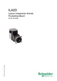
0198441113634, V2.02, 03.2012<br />
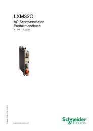
<strong>ILA2E</strong> EtherCAT<br />
<strong>Lexium</strong> Integrated Drive<br />
<strong>Product</strong> <strong>manual</strong><br />
V2.02, 03.2012<br />
www.schneider-electric.com
Important information <strong>ILA2E</strong> EtherCAT<br />
Important information<br />
This <strong>manual</strong> is part of the product.<br />
Carefully read this <strong>manual</strong> and observe all instructions.<br />
Keep this <strong>manual</strong> for future reference.<br />
Hand this <strong>manual</strong> and all other pertinent product documentation over<br />
to all users of the product.<br />
Carefully read and observe all safety instructions and the chapter<br />
"Before you begin - safety information".<br />
Some products are not available in all countries.<br />
For information on the availability of products, please consult the catalog.<br />
Subject to technical modifications without notice.<br />
All details provided are technical data which do not constitute warranted<br />
qualities.<br />
Most of the product designations are registered trademarks of their<br />
respective owners, even if this is not explicitly indicated.<br />
2 <strong>Lexium</strong> Integrated Drive<br />
0198441113634, V2.02, 03.2012
0198441113634, V2.02, 03.2012<br />
<strong>ILA2E</strong> EtherCAT Table of contents<br />
Table of contents<br />
Important information 2<br />
Table of contents 3<br />
About this <strong>manual</strong> 9<br />
Further reading 10<br />
1 Introduction 11<br />
1.1 Device overview 11<br />
1.2 Components and interfaces 12<br />
1.2.1 Components 13<br />
1.2.2 Interfaces 14<br />
1.3 Nameplate 15<br />
1.4 Type code 16<br />
2 Before you begin - safety information 17<br />
2.1 Qualification of personnel 17<br />
2.2 Intended use 17<br />
2.3 Hazard categories 18<br />
2.4 Basic information 19<br />
2.5 Functional safety 20<br />
2.6 Standards and terminology 20<br />
3 Technical Data 21<br />
3.1 Ambient conditions 21<br />
3.2 Mechanical data 23<br />
3.2.1 Mounting position 23<br />
3.2.2 Dimensions 23<br />
3.3 Electrical Data 24<br />
3.3.1 Supply voltage VDC at CN1 24<br />
3.3.2 Fieldbus at CN2 25<br />
3.3.3 Commissioning at CN3 25<br />
3.3.4 24V signals at CN4 25<br />
3.3.5 STO safety function at CN5 and CN6 26<br />
3.4 Conditions for UL 508C 26<br />
3.5 Certifications 27<br />
3.6 Declaration of conformity 28<br />
3.7 TÜV certificate for functional safety 29<br />
<strong>Lexium</strong> Integrated Drive 3
Table of contents <strong>ILA2E</strong> EtherCAT<br />
4 Basics 31<br />
4.1 Functional safety 31<br />
5 Engineering 33<br />
5.1 Configurable inputs and outputs 33<br />
5.2 External power supply units 33<br />
5.2.1 Supply voltage 33<br />
5.3 Wiring concept 35<br />
5.4 Safety function STO ("Safe Torque Off") 36<br />
5.4.1 Definitions 36<br />
5.4.2 Function 36<br />
5.4.3 Requirements for using the safety function 37<br />
5.4.4 Application examples STO 39<br />
5.5 Monitoring functions 40<br />
6 Installation 41<br />
6.1 Electromagnetic compatibility, EMC 42<br />
6.2 Mechanical installation 44<br />
6.3 Electrical installation 46<br />
6.3.1 Overview of the connections 47<br />
6.3.2 Connection via cable entry 48<br />
6.3.3 Connection via industrial connectors 51<br />
6.3.4 Connection of VDC supply voltage 52<br />
6.3.5 Connection Ethernet fieldbus interface 55<br />
6.3.6 RS485 interface connection 58<br />
6.3.7 24V signal interface connection 59<br />
6.3.8 Connection of STO safety function 61<br />
6.4 Connection accessories 63<br />
6.4.1 Accessory "Insert kit, 3x I/O" 63<br />
6.4.2 Accessory "Insert kit, 2x I/O, 1x STO in" 63<br />
6.4.3 Accessory "Insert kit, 1x STO in, 1x STO out" 63<br />
6.4.4 Accessory "Insert kit, 4x I/O, 1x STO in, 1x STO out" 64<br />
6.5 Checking wiring 64<br />
7 Commissioning 65<br />
7.1 Overview 67<br />
7.2 Drive profile and ESI file 68<br />
7.3 Add the product as an NC axis in "TwinCAT". 69<br />
7.3.1 Adding the product using the drive profile PLCopen 69<br />
7.3.2 Adding the product using the drive profile CANopen CiA 402 69<br />
7.3.2.1 Adding the product to TwinCAT 69<br />
7.3.2.2 Process data 70<br />
7.3.2.3 Setting monitoring of the position deviation 70<br />
7.3.2.4 Setting the scaling factor 71<br />
7.3.2.5 Setting homing 71<br />
7.3.2.6 List of the startup parameters 72<br />
4 <strong>Lexium</strong> Integrated Drive<br />
0198441113634, V2.02, 03.2012
0198441113634, V2.02, 03.2012<br />
<strong>ILA2E</strong> EtherCAT Table of contents<br />
7.3.3 Setting EtherCAT "Identification" 75<br />
7.4 Commissioning procedure 76<br />
7.4.1 <strong>Lexium</strong> CT commissioning software 77<br />
7.4.2 Setting basic parameters and limit values 79<br />
7.4.3 Digital inputs / outputs 82<br />
7.4.4 Testing the signals of the limit switches 83<br />
7.4.5 Testing the safety function STO 84<br />
7.4.6 Releasing the holding brake <strong>manual</strong>ly 85<br />
7.4.7 Checking the direction of movement 86<br />
7.4.8 Setting parameters for encoder 87<br />
7.4.9 Web server 90<br />
7.5 Controller optimization with step response 93<br />
7.5.1 Controller structure 93<br />
7.5.2 Optimization 94<br />
7.5.3 Optimizing the velocity controller 95<br />
7.5.4 Checking and optimizing default settings 98<br />
7.5.5 Optimizing the position controller 100<br />
8 Operation 103<br />
8.1 Overview of operating modes 103<br />
8.2 Access channels 104<br />
8.2.1 Access channel Ethernet fieldbus 104<br />
8.2.2 Access channel commissioning software 105<br />
8.2.3 Access channel signal input 105<br />
8.3 Operating states 106<br />
8.3.1 State diagram 106<br />
8.3.2 Indicating the operating states 109<br />
8.3.3 Changing operating states 111<br />
8.4 Starting and changing operating modes 113<br />
8.4.1 Starting the operating mode 114<br />
8.4.2 Changing the operating mode 115<br />
8.5 Operating modes 116<br />
8.5.1 Operating mode Cyclic Synchronous Position 116<br />
8.5.2 Operating mode Jog 117<br />
8.5.2.1 Example of a movement via DS402 objects 121<br />
8.5.3 Operating mode Speed Control 122<br />
8.5.4 Operating mode Profile Velocity 123<br />
8.5.4.1 Parameterization 123<br />
8.5.4.2 Example of a movement via DS402 objects 125<br />
8.5.5 Operating mode Profile Position 126<br />
8.5.5.1 Parameterization 127<br />
8.5.5.2 Example of a movement via DS402 objects 130<br />
8.5.6 Operating mode Homing 132<br />
8.5.6.1 Parameterization, general 134<br />
8.5.6.2 Reference movement without index pulse 137<br />
8.5.6.3 Reference movement with index pulse 140<br />
8.5.6.4 Reference movement to the index pulse 143<br />
8.5.6.5 Homing by position setting 144<br />
8.5.6.6 Example of a movement via DS402 objects 145<br />
<strong>Lexium</strong> Integrated Drive 5
Table of contents <strong>ILA2E</strong> EtherCAT<br />
8.6 Functions 146<br />
8.6.1 Monitoring functions 146<br />
8.6.1.1 Status monitoring during operation 146<br />
8.6.1.2 Positioning range 147<br />
8.6.1.3 Monitoring internal signals 150<br />
8.6.2 Scaling 155<br />
8.6.3 Motion profile 158<br />
8.6.4 Quick Stop 161<br />
8.6.5 Halt 163<br />
8.6.6 Fast position capture 165<br />
8.6.7 Standstill window 168<br />
8.6.8 Holding brake 170<br />
8.6.9 Configurable inputs and outputs 172<br />
8.6.9.1 Description of functions for signal inputs 173<br />
8.6.9.2 Description of functions for signal outputs 173<br />
8.6.9.3 Configuration of the signal inputs and outputs 174<br />
8.6.10 Changing the direction of movement 177<br />
8.6.11 Restoring default values 179<br />
8.6.11.1 Resetting user-defined parameters 179<br />
8.6.11.2 Restoring the factory settings 179<br />
9 Examples 181<br />
9.1 General information 181<br />
9.2 Wiring examples 181<br />
10 Diagnostics and troubleshooting 183<br />
10.1 Service 183<br />
10.2 Error indication 183<br />
10.2.1 State diagram 184<br />
10.2.2 EtherCAT state machine 184<br />
10.2.3 Error detection via the state machine 185<br />
10.2.4 Status LEDs 186<br />
10.2.4.1 Device LEDs 186<br />
10.2.4.2 EtherCAT LEDs 187<br />
10.2.5 Diagnostics via Web server 188<br />
10.2.6 Error indication using the commissioning software 188<br />
10.2.7 Error indication via the fieldbus 189<br />
10.2.8 Response in the case of invalid communication objects 190<br />
10.3 Troubleshooting 191<br />
10.3.1 Fieldbus communication 191<br />
10.3.2 Troubleshooting of errors sorted by error bit 192<br />
10.3.3 Table of warnings and errors by range 195<br />
11 Parameters 205<br />
11.1 Representation of the parameters 206<br />
11.1.1 Decimal numbers for fieldbus 207<br />
11.2 Object dictionary 207<br />
11.2.1 Communication profile range 207<br />
11.3 List of parameters 210<br />
6 <strong>Lexium</strong> Integrated Drive<br />
0198441113634, V2.02, 03.2012
0198441113634, V2.02, 03.2012<br />
<strong>ILA2E</strong> EtherCAT Table of contents<br />
12 Accessories and spare parts 245<br />
12.1 Accessories 245<br />
12.2 Gearbox 247<br />
13 Service, maintenance and disposal 249<br />
13.1 Service address 250<br />
13.2 Maintenance 250<br />
13.2.1 Lifetime STO safety function 250<br />
13.3 Replacing devices 251<br />
13.4 Shipping, storage, disposal 252<br />
14 Glossary 253<br />
14.1 Units and conversion tables 253<br />
14.1.1 Length 253<br />
14.1.2 Mass 253<br />
14.1.3 Force 253<br />
14.1.4 Power 253<br />
14.1.5 Rotation 254<br />
14.1.6 Torque 254<br />
14.1.7 Moment of inertia 254<br />
14.1.8 Temperature 254<br />
14.1.9 Conductor cross section 254<br />
14.2 Terms and Abbreviations 255<br />
15 Index 259<br />
<strong>Lexium</strong> Integrated Drive 7
<strong>ILA2E</strong> EtherCAT<br />
8 <strong>Lexium</strong> Integrated Drive<br />
0198441113634, V2.02, 03.2012
0198441113634, V2.02, 03.2012<br />
<strong>ILA2E</strong> EtherCAT About this <strong>manual</strong><br />
About this <strong>manual</strong><br />
This <strong>manual</strong> is valid for <strong>ILA2E</strong> standard products. Chapter<br />
"1 Introduction" lists the type code for this product. The type code<br />
allows you to identify whether your product is a standard product or a<br />
customized version.<br />
Source <strong>manual</strong>s The latest versions of the <strong>manual</strong>s can be downloaded from the Internet<br />
at:<br />
http://www.schneider-electric.com<br />
Source CAD data For easier engineering, CAD data (EPLAN macros or drawings) are<br />
available for download from the Internet at:<br />
http://www.schneider-electric.com<br />
Corrections and suggestions We always try to further optimize our <strong>manual</strong>s. We welcome your suggestions<br />
and corrections.<br />
Please get in touch with us by e-mail:<br />
techcomm@schneider-electric.com.<br />
Work steps If work steps must be performed consecutively, this sequence of steps<br />
is represented as follows:<br />
■ Special prerequisites for the following work steps<br />
▶ Step 1<br />
◁ Specific response to this work step<br />
▶ Step 2<br />
If a response to a work step is indicated, this allows you to verify that<br />
the work step has been performed correctly.<br />
Unless otherwise stated, the individual steps must be performed in the<br />
specified sequence.<br />
Making work easier Information on making work easier is highlighted by this symbol:<br />
Sections highlighted this way provide supplementary information on<br />
making work easier.<br />
Parameters In text sections, parameters are shown with the parameter name, for<br />
example _IO_act. The way parameters are represented in tables is<br />
explained in the chapter Parameters. The parameter list is sorted<br />
alphabetically by parameter name.<br />
SI units SI units are the original values. Converted units are shown in brackets<br />
behind the original value; they may be rounded.<br />
Example:<br />
Minimum conductor cross section: 1.5 mm 2 (AWG 14)<br />
Inverted signals Inverted signals are represented by an overline, for example STO_A or<br />
STO_B.<br />
Glossary Explanations of special technical terms and abbreviations.<br />
<strong>Lexium</strong> Integrated Drive 9
About this <strong>manual</strong> <strong>ILA2E</strong> EtherCAT<br />
Further reading<br />
Index List of keywords with references to the corresponding page numbers.<br />
Recommended literature for further reading:<br />
• Ellis, George: Control System Design Guide. Academic Press<br />
• Kuo, Benjamin; Golnaraghi, Farid: Automatic Control Systems.<br />
John Wiley & Sons<br />
User associations http://www.ethercat.org<br />
10 <strong>Lexium</strong> Integrated Drive<br />
0198441113634, V2.02, 03.2012
0198441113634, V2.02, 03.2012<br />
<strong>ILA2E</strong> EtherCAT 1 Introduction<br />
1 Introduction<br />
1.1 Device overview<br />
Figure 1: Device overview<br />
1<br />
The "<strong>Lexium</strong> Integrated Drive" consists of a servo motor and integrated<br />
drive. The product integrates interfaces, control electronics, a<br />
holding brake (optional) and the power stage.<br />
Supply of reference values The "<strong>Lexium</strong> Integrated Drive" moves the motor according to the commands<br />
received by a fieldbus master, for example, a PLC or a PC.<br />
Integrated safety function "Safe<br />
Torque Off" STO<br />
The integrated safety function STO (IEC 61800-5-2) allows for a category<br />
0 stop as per IEC 60204-1 without external power contactors. It is<br />
not necessary to interrupt the supply voltage for a category 0 stop.<br />
This reduces the system costs and the response times.<br />
Drive profile The product supports the following drive profiles:<br />
• PLCopen (vendor-specific)<br />
• CANopen CiA 402<br />
TwinCAT support The following TwinCAT functions are supported:<br />
• TwinCAT-Systeme PLC, NC PTP, NC I and CNC<br />
• TwinCAT libraries using TcMc.lib or TcMc2.lib<br />
• TwinCAT homing methods Plc CAM and Software Sync<br />
<strong>Lexium</strong> Integrated Drive 11
1 Introduction <strong>ILA2E</strong> EtherCAT<br />
1.2 Components and interfaces<br />
5<br />
6<br />
7<br />
Figure 2: Components and interfaces<br />
1<br />
2<br />
3<br />
12<br />
4<br />
11<br />
5<br />
8<br />
6 7<br />
(1) AC synchronous servo motor<br />
(2) Holding brake (optional)<br />
(3) Encoder<br />
(4) Electronics housing<br />
(5) Insert for sealing (accessory)<br />
(6) Insert with cable entry (accessory)<br />
(7) I/O insert with industrial connector (accessory)<br />
(8) Switches for settings<br />
(9) Cover of electronics housing, must not be removed<br />
(10) Cover of connector housing, to be removed for installation<br />
(11) Cover with industrial connector for VDC supply voltage and<br />
IN/OUT fieldbus connection (optional)<br />
(12) Electrical interfaces<br />
12 <strong>Lexium</strong> Integrated Drive<br />
9<br />
10<br />
0198441113634, V2.02, 03.2012
0198441113634, V2.02, 03.2012<br />
<strong>ILA2E</strong> EtherCAT 1 Introduction<br />
1.2.1 Components<br />
Motor The motor is a brushless AC synchronous servo motor with 3-phase<br />
technology. The motor has a high power density due to the use of the<br />
latest magnetic materials and an optimized design.<br />
Electronics The electronic system comprises control electronics and power stage.<br />
The product can be parameterized and controlled via the fieldbus<br />
interface.<br />
Four digital 24V signals are also available. Each of these signals can<br />
be used as an input or output.<br />
Encoder The standard product operates with a singleturn encoder.<br />
The singleturn encoder has an internal resolution of 32768 increments<br />
per revolution.<br />
Scaling of the product is set to 16384 user-defined units per revolution.<br />
The product can optionally be equipped with a multiturn encoder. The<br />
multiturn encoder covers a range of 4096 motor revolutions.<br />
Holding brake The product can optionally be equipped with an integrated holding<br />
brake. The holding brake is controlled automatically.<br />
<strong>Lexium</strong> Integrated Drive 13
1 Introduction <strong>ILA2E</strong> EtherCAT<br />
1.2.2 Interfaces<br />
Supply voltage VDC The supply voltage VDC supplies the control electronics and the power<br />
stage.<br />
Ethernet fieldbus interface The product features an Ethernet fieldbus interface. This interface is<br />
used for controlling and commissioning the drive.<br />
EtherCAT is an Ethernet-based fieldbus system. The technology is<br />
standardized as per the international standards IEC 61158 and<br />
IEC 61784 as well as ISO 15745-4.<br />
EtherCAT is a real-time Ethernet system that lends itself for use in<br />
cycle-synchronous motion control applications.<br />
EtherCAT® is a registered trademark and patented technology<br />
licenced by Beckhoff Automation GmbH, Germany.<br />
RS485 interface An RS485 interface is provided in addition to the fieldbus interface.<br />
The RS485 interface is also used to commission the product.<br />
You can also use the RS485 interface and the commissioning software<br />
to monitor the product during operation. It is possible to establish<br />
simultaneous connections via the commissioning interface and the<br />
fieldbus.<br />
24 V signal interface 4 digital 24V signals are available. Each of these signals can be used<br />
as an input or output.<br />
The 24V signals are available to the master controller. However, it is<br />
also possible to parameterize special functions such as connection of<br />
limit switches.<br />
14 <strong>Lexium</strong> Integrated Drive<br />
0198441113634, V2.02, 03.2012
0198441113634, V2.02, 03.2012<br />
<strong>ILA2E</strong> EtherCAT 1 Introduction<br />
1.3 Nameplate<br />
The nameplate contains the following data:<br />
1<br />
2<br />
3<br />
4<br />
5<br />
6<br />
7<br />
IL ...<br />
Figure 3: Nameplate<br />
I ...<br />
UN 000 Vrms<br />
MN 0.00 Nm<br />
Imax 0.00 Arms<br />
nN 0000 rpm<br />
DOM 00.00.00<br />
Insulation class<br />
Tambmax 00 C˚<br />
PR 0.00 Rev 0.000 RS 00<br />
ID<br />
SN<br />
000 ...<br />
00000000<br />
(1) Type code<br />
(2) Type code (old designation)<br />
(3) Nominal voltage<br />
(4) Nominal torque<br />
(5) Maximum input current<br />
(6) Nominal speed of rotation<br />
(7) Date of manufacture<br />
(8) Thermal class<br />
(9) Maximum surrounding air temperature<br />
(10) Firmware version<br />
(11) Hardware version<br />
(12) Firmware number<br />
(13) Order no.<br />
(14) Serial number<br />
C<br />
US<br />
Made in Germany<br />
<strong>Lexium</strong> Integrated Drive 15<br />
8<br />
9<br />
10<br />
11<br />
12<br />
13<br />
14
1 Introduction <strong>ILA2E</strong> EtherCAT<br />
1.4 Type code<br />
Motor<br />
ILA = Servo motor<br />
Supply voltage<br />
2 = 24 ... 48 Vdc<br />
Communication interface<br />
E = EtherCAT<br />
Size<br />
57 = 57 mm<br />
Length<br />
1 = 1 stack<br />
2 = 2 stacks<br />
Winding<br />
P = Medium speed of rotation/medium torque<br />
T = High speed of rotation/low torque<br />
Connection version<br />
B = Printed circuit board connector<br />
C = Industrial connector<br />
Position capture<br />
1 = Singleturn encoder<br />
2 = Multiturn encoder 1)<br />
Holding brake<br />
A = Without holding brake<br />
F = With holding brake 2)<br />
Gearbox<br />
0 = Without gearbox<br />
Reserved<br />
1) Not available in combination with the holding brake option.<br />
2) Not available in combination with the servo multiturn encoder option.<br />
ILA 2 E 57 1 P B 1 A 0 --<br />
Customized product In the case of a customized product, position 9 is an "S".<br />
Positions 10 ... 13 are the number of the customized product.<br />
Example: IL∙ ∙ ∙ ∙ ∙ ∙S1234--<br />
16 <strong>Lexium</strong> Integrated Drive<br />
0198441113634, V2.02, 03.2012
0198441113634, V2.02, 03.2012<br />
<strong>ILA2E</strong> EtherCAT 2 Before you begin - safety information<br />
2 Before you begin - safety information<br />
2.1 Qualification of personnel<br />
2.2 Intended use<br />
2<br />
Only appropriately trained persons who are familiar with and understand<br />
the contents of this <strong>manual</strong> and all other pertinent product documentation<br />
are authorized to work on and with this product. In addition,<br />
these persons must have received safety training to recognize and<br />
avoid hazards involved. These persons must have sufficient technical<br />
training, knowledge and experience and be able to foresee and detect<br />
potential hazards that may be caused by using the product, by changing<br />
the settings and by the mechanical, electrical and electronic equipment<br />
of the entire system in which the product is used.<br />
All persons working on and with the product must be fully familiar with<br />
all applicable standards, directives, and accident prevention regulations<br />
when performing such work.<br />
This product is a motor with an integrated drive and intended for<br />
industrial use according to this <strong>manual</strong>.<br />
The product may only be used in compliance with all applicable safety<br />
regulations and directives, the specified requirements and the technical<br />
data.<br />
Prior to using the product, you must perform a risk assessment in view<br />
of the planned application. Based on the results, the appropriate<br />
safety measures must be implemented.<br />
Since the product is used as a component in an entire system, you<br />
must ensure the safety of persons by means of the design of this<br />
entire system (for example, machine design).<br />
Operate the product only with the specified cables and accessories.<br />
Use only genuine accessories and spare parts.<br />
The product must NEVER be operated in explosive atmospheres<br />
(hazardous locations, Ex areas).<br />
Any use other than the use explicitly permitted is prohibited and can<br />
result in hazards.<br />
Electrical equipment should be installed, operated, serviced, and<br />
maintained only by qualified personnel.<br />
<strong>Lexium</strong> Integrated Drive 17
2 Before you begin - safety information <strong>ILA2E</strong> EtherCAT<br />
2.3 Hazard categories<br />
Safety instructions to the user are highlighted by safety alert symbols<br />
in the <strong>manual</strong>. In addition, labels with symbols and/or instructions are<br />
attached to the product that alert you to potential hazards.<br />
Depending on the seriousness of the hazard, the safety instructions<br />
are divided into 4 hazard categories.<br />
DANGER<br />
DANGER indicates an imminently hazardous situation, which, if not<br />
avoided, will result in death or serious injury.<br />
WARNING<br />
WARNING indicates a potentially hazardous situation, which, if not<br />
avoided, can result in death, serious injury, or equipment damage.<br />
CAUTION<br />
CAUTION indicates a potentially hazardous situation, which, if not<br />
avoided, can result in injury or equipment damage.<br />
CAUTION<br />
CAUTION used without the safety alert symbol, is used to address<br />
practices not related to personal injury (e.g. can result in equipment<br />
damage).<br />
18 <strong>Lexium</strong> Integrated Drive<br />
0198441113634, V2.02, 03.2012
0198441113634, V2.02, 03.2012<br />
<strong>ILA2E</strong> EtherCAT 2 Before you begin - safety information<br />
2.4 Basic information<br />
UNEXPECTED MOVEMENT<br />
WARNING<br />
Drives may perform unexpected movements because of incorrect<br />
wiring, incorrect settings, incorrect data or other errors.<br />
Interference (EMC) may cause unpredictable responses in the system.<br />
• Carefully install the wiring in accordance with the EMC requirements.<br />
• Do not operate the product with unknown settings or data.<br />
• Perform a comprehensive commissioning test.<br />
Failure to follow these instructions can result in death or serious<br />
injury.<br />
LOSS OF CONTROL<br />
WARNING<br />
• The designer of any control scheme must consider the potential<br />
failure modes of control paths and, for certain critical functions,<br />
provide a means to achieve a safe state during and after a path<br />
failure. Examples of critical control functions are emergency stop,<br />
overtravel stop, power outage and restart.<br />
• Separate or redundant control paths must be provided for critical<br />
functions.<br />
• System control paths may include communication links. Consideration<br />
must be given to the implication of unanticipated transmission<br />
delays or failures of the link.<br />
• Observe all accident prevention regulations and local safety<br />
guidelines. 1)<br />
• Each implementation of the product must be individually and thoroughly<br />
tested for proper operation before being placed into service.<br />
Failure to follow these instructions can result in death or serious<br />
injury.<br />
1) For USA: Additional information, refer to NEMA ICS 1.1 (latest edition), “Safety<br />
Guidelines for the Application, Installation, and Maintenance of Solid State Control”<br />
and to NEMA ICS 7.1 (latest edition), “Safety Standards for Construction and Guide<br />
for Selection, Installation and Operation of Adjustable-Speed Drive Systems”.<br />
WARNING<br />
UNEXPECTED BEHAVIOR AND DESTRUCTION OF SYSTEM COMPO-<br />
NENTS<br />
When you work on the wiring and when you unplug or plug in connectors,<br />
this may cause unexpected behavior and destruction of system<br />
components.<br />
• Switch the power supply off before working on the wiring.<br />
Failure to follow these instructions can result in death, serious<br />
injury or equipment damage.<br />
<strong>Lexium</strong> Integrated Drive 19
2 Before you begin - safety information <strong>ILA2E</strong> EtherCAT<br />
2.5 Functional safety<br />
2.6 Standards and terminology<br />
Using the safety functions integrated in this product requires careful<br />
planning. See chapter "5.4 Safety function STO ("Safe Torque Off")",<br />
page 36 for additional information.<br />
Technical terms, terminology and the corresponding descriptions in<br />
this <strong>manual</strong> are intended to use the terms or definitions of the pertinent<br />
standards.<br />
In the area of drive systems, this includes, but is not limited to, terms<br />
such as "safety function", "safe state", "fault", "fault reset", "failure",<br />
"error", "error message", "warning", "warning message", etc.<br />
Among others, these standards include:<br />
• IEC 61800: "Adjustable speed electrical power drive systems"<br />
• IEC 61158: "Digital data communications for measurement and<br />
control – Fieldbus for use in industrial control systems"<br />
• IEC 61784: "Industrial communication networks – Profiles"<br />
• IEC 61508: "Functional safety of electrical/electronic/programmable<br />
electronic safety-related systems"<br />
Also see the glossary at the end of this <strong>manual</strong>.<br />
20 <strong>Lexium</strong> Integrated Drive<br />
0198441113634, V2.02, 03.2012
0198441113634, V2.02, 03.2012<br />
<strong>ILA2E</strong> EtherCAT 3 Technical Data<br />
3 Technical Data<br />
3.1 Ambient conditions<br />
Ambient conditions transportation<br />
and storage<br />
Climatic environmental conditions<br />
operation<br />
3<br />
This chapter contains information on the ambient conditions and on<br />
the mechanical and electrical properties of the product family and the<br />
accessories.<br />
The environment during transport and storage must be dry and free<br />
from dust. The maximum vibration and shock load must be within the<br />
specified limits.<br />
Temperature [°C] -25 ... +70<br />
The maximum permissible ambient temperature during operation<br />
depends on the mounting distances between the devices and on the<br />
required power. Observe the pertinent instructions in the chapter<br />
"6 Installation".<br />
Ambient temperature 1) [°C] 0 ... 40<br />
Ambient temperature with current<br />
reduction of 2 [%] per Kelvin 1)<br />
Max. temperature of power stage<br />
2)<br />
[°C] 40 ... 55<br />
[°C] 105<br />
Max. temperature of motor 3) [°C] 110<br />
1) Limit values with flanged motor (for example, steel plate 300x300x10 mm)<br />
2) Can be read via parameter<br />
3) Measured on the surface<br />
The following relative humidity is permissible during operation:<br />
Relative humidity [%] 15 ... 85<br />
The installation altitude is defined as altitude above mean sea level.<br />
Installation altitude without derating<br />
[m]
3 Technical Data <strong>ILA2E</strong> EtherCAT<br />
IP degree of protection The product has the following IP degree of protection as per IEC<br />
60529.<br />
Degree of protection when the<br />
safety function is used<br />
Vibration and shock<br />
EMC<br />
1 2<br />
Figure 4: IP degree of protection<br />
Item Degree of<br />
protection<br />
1 Shaft bushing<br />
Shaft bushing with GBX gearbox (accessory)<br />
IP41<br />
IP54<br />
2 Housing, except shaft bushing IP54<br />
The total degree of protection is determined by the component with<br />
the lowest degree of protection.<br />
You must ensure that conductive substances cannot get into the product<br />
(pollution degree 2). Conductive substances may cause the safety<br />
function to become inoperative.<br />
Vibration, sinusoidal Type test with 10 runs as per IEC<br />
60068-2-6<br />
0.15 [mm] (from 10 [Hz] ... 60 [Hz])<br />
20 [m/s 2 ] (from 60 [Hz] ... 500 [Hz])<br />
Shock, semi-sinusoidal Type test with 3 shocks in each direction<br />
as per IEC 60068-2-27<br />
150 [m/s 2 ] (11 [ms])<br />
Emission IEC 61800-3: Category C2<br />
IEC 61000-6-4<br />
EN 55022: Class A<br />
Immunity IEC 61800-3: second environment<br />
22 <strong>Lexium</strong> Integrated Drive<br />
0198441113634, V2.02, 03.2012
0198441113634, V2.02, 03.2012<br />
<strong>ILA2E</strong> EtherCAT 3 Technical Data<br />
3.2 Mechanical data<br />
3.2.1 Mounting position<br />
3.2.2 Dimensions<br />
5.5<br />
Ø 5.2<br />
Figure 5: Dimensions<br />
Mounting position The following mounting positions are defined and approved as per<br />
IEC 60034-7:<br />
• IM B5 drive shaft horizontal<br />
• IM V1 drive shaft vertical, shaft end down<br />
• IM V3 drive shaft vertical, shaft end up<br />
2 3<br />
47.14<br />
57.2<br />
47.14<br />
57.2<br />
92.2<br />
17<br />
M4 73<br />
1 1<br />
L<br />
9.5<br />
(1) Insert with cable entry (accessory)<br />
(2) Insert kit (accessory)<br />
(3) Industrial connector (option)<br />
ILA∙ ∙57... 1∙ ∙1A0 1∙ ∙2A0 1∙ ∙1F0<br />
Total length L [mm] 145.3 179.3 190.8<br />
ILA∙ ∙57... 2∙ ∙1A0 2∙ ∙2A0 2∙ ∙2F0<br />
Total length L [mm] 163.8 197.8 209.3<br />
<strong>Lexium</strong> Integrated Drive 23<br />
1.6<br />
20<br />
5.8<br />
Ø9 j6<br />
Ø 50 h8
3 Technical Data <strong>ILA2E</strong> EtherCAT<br />
3.3 Electrical Data<br />
Overview of printed circuit board<br />
connectors<br />
3.3.1 Supply voltage VDC at CN1<br />
7 1<br />
8 2<br />
9 3<br />
10 4<br />
11 5<br />
12 6<br />
CN2<br />
VDC<br />
CN1<br />
1 2 3<br />
4 5 6<br />
CN3<br />
0VDC<br />
Figure 6: Overview of printed circuit board connectors<br />
CN6<br />
1 2 3<br />
4 5 6<br />
CN4<br />
CN5<br />
ILA2∙571 ILA2∙572<br />
Nominal voltage 1) [Vdc] 24 / 48 24 / 48<br />
Limit values 1) [Vdc] 18 ... 55.2 18 ... 55.2<br />
Ripple at nominal voltage [Vpp] ≤3.6 ≤3.6<br />
Max. continuous current input 2)<br />
Winding type P<br />
Winding type T<br />
Peak input current<br />
Winding type P<br />
Winding type T<br />
[A]<br />
[A]<br />
5<br />
7.5<br />
7<br />
11<br />
1<br />
2<br />
7<br />
7.5<br />
8.5<br />
9<br />
Fuse to be connected upstream 3) [A] ≤16 ≤16<br />
1) If the product is to be used in compliance with UL 508C, note the information provided<br />
in chapter "3.4 Conditions for UL 508C".<br />
2) The actual power requirement is often significantly lower, because the maximum<br />
possible motor torque is usually not required for operation of a system.<br />
3) See chapter "5.2.1 Supply voltage"<br />
Inrush current Charging current for capacitor C=1500 µF<br />
24 <strong>Lexium</strong> Integrated Drive<br />
0198441113634, V2.02, 03.2012
0198441113634, V2.02, 03.2012<br />
<strong>ILA2E</strong> EtherCAT 3 Technical Data<br />
3.3.2 Fieldbus at CN2<br />
EtherCAT signals The EtherCAT signals comply with the IEEE 802.3 standard and are<br />
galvanically isolated.<br />
3.3.3 Commissioning at CN3<br />
3.3.4 24V signals at CN4<br />
Internal 24V signal supply and signal<br />
outputs<br />
Transmission protocol EtherCAT<br />
Transmission rate [<strong>MB</strong>it] 100<br />
Addressing methods Position addressing<br />
Node addressing<br />
Logical addressing<br />
Communication profile CoE, EoE<br />
Synchronization methods DC synchronous (Distributed<br />
Clock, Jitter
3 Technical Data <strong>ILA2E</strong> EtherCAT<br />
3.3.5 STO safety function at CN5 and CN6<br />
Data for maintenance plan and<br />
safety calculations<br />
3.4 Conditions for UL 508C<br />
Pollution degree<br />
The signal inputs are not not galvanically isolated.<br />
Logic 0 (Ulow) [V] -3 ... +4.5<br />
Logic 1 (Uhigh) [V] +15 ... +30<br />
Input current STO_A (PWRR_A)<br />
(typical at 24 [V])<br />
Input current STO_B (PWRR_B)<br />
(typical at 24 [ V])<br />
[mA] ≤10<br />
[mA] ≤3<br />
Debounce time [ms] 1 ... 5<br />
Detection of signal difference<br />
between STO_A (PWRR_A) and<br />
STO_B (PWRR_B)<br />
Response time (until disabling of<br />
power stage)<br />
Permitted test pulse width of<br />
upstream devices<br />
[s]
0198441113634, V2.02, 03.2012<br />
<strong>ILA2E</strong> EtherCAT 3 Technical Data<br />
3.5 Certifications<br />
<strong>Product</strong> certifications:<br />
Certified by Assigned number<br />
TÜV Nord SAS-1728/08<br />
UL File E 153659<br />
Certified safety function This product has the following certified safety function:<br />
• Safety function STO "Safe Torque Off" (IEC 61800-5-2)<br />
<strong>Lexium</strong> Integrated Drive 27
3 Technical Data <strong>ILA2E</strong> EtherCAT<br />
3.6 Declaration of conformity<br />
SCHNEIDER ELECTRIC MOTION DEUTSCHLAND GmbH<br />
Breslauer Str. 7 D-77933 Lahr<br />
EC DECLARATION OF CONFORMITY<br />
YEAR 2010<br />
according to EC Directive on Machinery 2006/42/EC<br />
according to EC Directive EMC 2004/108/EC<br />
according to EC Directive Low Voltage 2006/95/EC<br />
We hereby declare that the products listed below meet the requirements of the EC<br />
Directives indicated with respect to design, construction and version distributed by us. This<br />
declaration becomes invalid in the case of any modification to the products not authorized<br />
by us.<br />
Designation: Motors with integrated control electronics<br />
Type: ILA, ILE, ILS<br />
Applied<br />
harmonized<br />
standards,<br />
especially:<br />
Applied<br />
national standards<br />
and technical<br />
specifications,<br />
especially:<br />
Company stamp:<br />
EN ISO 13849-1:2008, Performance Level "d" (category 3)<br />
EN 61800-3:2004, second environment<br />
EN 62061:2005, SILcl 2<br />
EN 61508:2001, SIL 2<br />
UL 508C<br />
<strong>Product</strong> documentation<br />
Date/Signature: 12 October 2010<br />
Name/Department: Wolfgang Brandstätter/Development<br />
28 <strong>Lexium</strong> Integrated Drive<br />
0198441113634, V2.02, 03.2012
0198441113634, V2.02, 03.2012<br />
<strong>ILA2E</strong> EtherCAT 3 Technical Data<br />
3.7 TÜV certificate for functional safety<br />
<strong>Lexium</strong> Integrated Drive 29
3 Technical Data <strong>ILA2E</strong> EtherCAT<br />
30 <strong>Lexium</strong> Integrated Drive<br />
0198441113634, V2.02, 03.2012
0198441113634, V2.02, 03.2012<br />
<strong>ILA2E</strong> EtherCAT 4 Basics<br />
4 Basics<br />
4.1 Functional safety<br />
Integrated safety function "Safe<br />
Torque Off" STO<br />
4<br />
Automation and safety engineering are two areas that were completely<br />
separated in the past but recently have become more and<br />
more integrated. Engineering and installation of complex automation<br />
solutions are greatly simplified by integrated safety functions.<br />
Usually, the safety engineering requirements depend on the application.<br />
The level of the requirements results from the risk and the hazard<br />
potential arising from the specific application.<br />
The integrated safety function STO (IEC 61800-5-2) allows for a category<br />
0 stop as per IEC 60204-1 without external power contactors. It is<br />
not necessary to interrupt the supply voltage for a category 0 stop.<br />
This reduces the system costs and the response times.<br />
IEC 61508 standard The standard IEC 61508 "Functional safety of electrical/electronic/<br />
programmable electronic safety-related systems" covers the safetyrelated<br />
function. Instead of a single component, an entire function<br />
chain (for example, from a sensor through the logical processing units<br />
to the actuator) is considered as a unit. This function chain must meet<br />
the requirements of the specific safety integrity level as a whole. Systems<br />
and components that can be used in various applications for<br />
safety tasks with comparable risk levels can be developed on this<br />
basis.<br />
SIL, Safety Integrity Level The standard IEC 61508 defines 4 safety integrity levels (SIL) for<br />
safety functions. SIL1 is the lowest level and SIL4 is the highest level.<br />
A hazard and risk analysis serves as a basis for determining the<br />
required safety integrity level. This is used to decide whether the relevant<br />
function chain is to be considered as a safety function and which<br />
hazard potential it must cover.<br />
<strong>Lexium</strong> Integrated Drive 31
4 Basics <strong>ILA2E</strong> EtherCAT<br />
PFH, Probability of a dangerous<br />
hardware failure per hour<br />
To maintain the safety function, the IEC 61508 standard requires various<br />
levels of measures for avoiding and controlling faults, depending<br />
on the required SIL. All components of a safety function must be subjected<br />
to a probability assessment to evaluate the effectiveness of the<br />
measures implemented for controlling faults. This assessment determines<br />
the PFH (probability of a dangerous failure per hour) for a<br />
safety system. This is the probability per hour that a safety system<br />
fails in a hazardous manner and the safety function cannot be correctly<br />
executed. Depending on the SIL, the PFH must not exceed certain<br />
values for the entire safety system. The individual PFH values of a<br />
function chain are added. The result must not exceed the maximum<br />
value specified in the standard.<br />
SIL PFH at high demand or continuous demand<br />
4 ≥10 -9 ...
0198441113634, V2.02, 03.2012<br />
<strong>ILA2E</strong> EtherCAT 5 Engineering<br />
5 Engineering<br />
5.1 Configurable inputs and outputs<br />
5.2 External power supply units<br />
5.2.1 Supply voltage<br />
5<br />
This chapter contains information on the application of the product<br />
that is vital in the engineering phase.<br />
This product has digital inputs and outputs that can be configured.<br />
This standard assignment can be adapted to the requirements of the<br />
customer's installation. See chapter<br />
"8.6.9 Configurable inputs and outputs" for additional information.<br />
DANGER<br />
ELECTRIC SHOCK CAUSED BY INCORRECT POWER SUPPLY UNIT<br />
The VDC and +24VDC supply voltages are connected with many<br />
exposed signal connections in the drive system.<br />
• Use a power supply unit that meets the PELV (Protective Extra<br />
Low Voltage) requirements.<br />
• Connect the negative output of the power supply unit to PE<br />
(ground).<br />
Failure to follow these instructions will result in death or serious<br />
injury.<br />
General The power supply unit must be rated for the power requirements of the<br />
drive. The input current can be found in the technical data.<br />
The actual power requirements are often significantly lower because<br />
the maximum possible motor torque is usually not required for normal<br />
operation of a system.<br />
When designing the system, note that the input current of the drive is<br />
higher during the motor acceleration phase than during constant<br />
movement.<br />
The VDC power supply for this product is the DC bus.<br />
<strong>Lexium</strong> Integrated Drive 33
5 Engineering <strong>ILA2E</strong> EtherCAT<br />
Reverse polarity protection In the case of reverse polarity of the VDC supply voltage, there is a<br />
short-circuit in the drive. The product is continuous short circuit-proof<br />
up to a short-circuit current of a maximum of 15 A.<br />
If the power is supplied by a transformer power supply unit, several<br />
hundred amperes may flow for a short period of time in the event of<br />
reverse polarity. The drive is rated for this.<br />
Fuse to be connected upstream: circuit-breaker (type multi9 C60N by<br />
Schneider Electric, Cat.No.60112, rated current 15 A, trip characteristic<br />
C.) or blade fuse (FKS, max. 15 A) or fuse (5 x 20 mm, 10A slowblow).<br />
Regeneration condition Note the following for drives with high external moments of inertia or<br />
for highly dynamic applications:<br />
The motors regenerate energy during deceleration. The DC bus can<br />
absorb a limited amount of energy in the capacitors. Connecting additional<br />
capacitors to the DC bus increases the amount of energy that<br />
can be absorbed.<br />
If the capacity of the capacitors is exceeded, the excess energy must<br />
be discharged via internal or external braking resistors. If the energy is<br />
not discharged, an overvoltage monitor will shut off the power stage.<br />
Overvoltages can be limited by adding a braking resistor with a corresponding<br />
braking resistor controller.<br />
Braking resistor controllers can be found in chapter<br />
"12 Accessories and spare parts". See the product <strong>manual</strong> for a<br />
description of the braking resistor controller.<br />
WARNING<br />
LOSS OF CONTROL DUE TO REGENERATION CONDITION<br />
Regeneration conditions resulting from braking or external driving<br />
forces may increase the VDC supply voltage to an unexpected level.<br />
Components not rated for this voltage may be destroyed or cause<br />
misoperation.<br />
• Verify that all VDC consumers are rated for the voltage occurring<br />
during regeneration conditions (for example limit switches).<br />
• Use only power supply units that will not be damaged by regeneration<br />
conditions.<br />
• If necessary, use a braking resistor controller.<br />
Failure to follow these instructions can result in death, serious<br />
injury or equipment damage.<br />
Internal 24V signal power supply An internal 24V power supply for the sensor system is integrated in<br />
the product.<br />
The internal 24V signal power supply must not be connected to the<br />
internal 24V signal power supply of another product.<br />
34 <strong>Lexium</strong> Integrated Drive<br />
0198441113634, V2.02, 03.2012
0198441113634, V2.02, 03.2012<br />
<strong>ILA2E</strong> EtherCAT 5 Engineering<br />
5.3 Wiring concept<br />
Note the following for wiring the product:<br />
• Keep the voltage drop on the supply cables for the VDC supply voltage<br />
to less than 1 V. The reference potential of some interfaces<br />
are connected to 0VDC. At higher potential differences, the communication<br />
and control signals may be disturbed.<br />
Decentralized power supply units for VDC close to the drives are<br />
recommended in the case of great distances. Connect 0VDC of the<br />
individual power supply units with the largest possible conductor<br />
cross section.<br />
• Do not connect any other power supply in parallel with the internal<br />
24V signal supply (+24VDC_OUT). This may cause overloads of the<br />
internal 24V signal supply.<br />
• Connect the reference potential of signal wires only in the case of<br />
interfaces with galvanic isolation.<br />
In the case of interfaces without galvanic isolation, the reference<br />
potential is already connected via 0VDC. If 0VDC is interrupted, the<br />
current to the power stage would otherwise flow via these signal<br />
wires. This may damage these signal wires and the connected<br />
interfaces.<br />
Equipotential bonding conductors Potential differences can result in excessive currents on the cable<br />
shields. Use equipotential bonding conductors to reduce currents on<br />
the cable shields.<br />
The equipotential bonding conductor must be rated for the maximum<br />
current flowing. Practical experience has shown that the following conductor<br />
cross sections can be used:<br />
• 16 mm 2 (AWG 4) for equipotential bonding conductors up to a<br />
length of 200 m<br />
• 20 mm 2 (AWG 4) for equipotential bonding conductors with a<br />
length of more than 200 m<br />
<strong>Lexium</strong> Integrated Drive 35
5 Engineering <strong>ILA2E</strong> EtherCAT<br />
5.4 Safety function STO ("Safe Torque Off")<br />
5.4.1 Definitions<br />
Safety function STO<br />
(IEC 61800-5-2)<br />
See chapter 20 for information on using the IEC 61508 standard.<br />
The safety function STO ("Safe Torque Off") shuts off the motor torque<br />
safely. It is not necessary to interrupt the supply voltage. There is<br />
no monitoring for standstill.<br />
"Power Removal" The STO safety function ("Safe Torque Off") is also known as "Power<br />
Removal".<br />
Category 0 stop (IEC 60204-1) Stopping by immediate removal of power to the machine actuators<br />
(i.e. an uncontrolled stop).<br />
Category 1 stop (IEC 60204-1) Controlled stop with power available to the machine actuators to achieve<br />
the stop. Power is not interrupted until the stop is achieved.<br />
5.4.2 Function<br />
The STO safety function integrated into the product can be used to<br />
implement an "EMERGENCY STOP" (IEC 60204-1) for category 0<br />
stops. With an additional, approved EMERGENCY STOP safety relay<br />
module, it is also possible to implement category 1 stops.<br />
Function principle The STO safety function is triggered via 2 redundant inputs. The circuits<br />
of the two inputs must be separate so that there are two channels.<br />
The switching process must be simultaneous for both inputs (offset<br />
0198441113634, V2.02, 03.2012<br />
<strong>ILA2E</strong> EtherCAT 5 Engineering<br />
5.4.3 Requirements for using the safety function<br />
LOSS OF SAFETY FUNCTION<br />
WARNING<br />
Incorrect usage may cause a hazard due to the loss of the safety<br />
function.<br />
• Observe the requirements for using the safety function.<br />
Failure to follow these instructions can result in death or serious<br />
injury.<br />
Category 0 stop During a category 0 stop, the motor coasts down in an uncontrolled<br />
way. If access to the machine coasting down involves a hazard<br />
(results of the hazard and risk analysis), you must take appropriate<br />
measures.<br />
Category 1 stop A controlled stop must be triggered with a category 1 stop. The controlled<br />
stop is not monitored by the drive system. In the case of power<br />
outage or an error, a controlled stop is impossible. Final shutoff of the<br />
motor is achieved by switching off the two inputs of the STO safety<br />
function. The shutoff is usually controlled by a standard EMERGENCY<br />
STOP safety relay module with a safe time delay.<br />
Behavior of holding brake Triggering the STO safety function means that the delay time for<br />
motors with holding brake is not effective. The motor cannot generate<br />
holding torque to bridge the time to application of the holding brake.<br />
Check whether additional measures have to be taken; for example,<br />
this may cause the load of vertical axes to lower.<br />
Vertical axes, external forces If external forces act on the motor (vertical axis) and an unwanted<br />
movement, for example caused by gravity, could cause a hazard, the<br />
motor must not be operated without additional measures for fall protection.<br />
Unintended restart To avoid unintended restart of the motor after restoration of power (for<br />
example, after power outage), the parameter IO_AutoEnable must<br />
be set to "off". Note that a master controller must not trigger an unintended<br />
restart.<br />
Degree of protection when the<br />
safety function is used<br />
You must ensure that conductive substances cannot get into the product<br />
(pollution degree 2). Conductive substances may cause the safety<br />
function to become inoperative.<br />
Protected cable installation If short circuits and cross circuits can be expected in connection with<br />
safety-related signals and if they are not detected by upstream devices,<br />
protected cable installation as per ISO 13849‑2 is required.<br />
In the case of an unprotected cable installation, the two signals (both<br />
channels) of a safety function may be connected to external voltage if<br />
a cable is damaged. If the two channels are connected to external<br />
voltage, the safety function is no longer operative.<br />
<strong>Lexium</strong> Integrated Drive 37
5 Engineering <strong>ILA2E</strong> EtherCAT<br />
Data for maintenance plan and<br />
safety calculations<br />
Use the following data of the STO safety function for your maintenance<br />
plan and the safety calculations:<br />
Lifetime (IEC 61508) 20 years<br />
SFF (IEC 61508)<br />
Safe Failure Fraction<br />
HFT (IEC 61508)<br />
Hardware Fault Tolerance<br />
Type A subsystem<br />
Safety integrity level<br />
IEC 61508<br />
IEC 62061<br />
PFH (IEC 61508)<br />
Probability of Dangerous Hardware<br />
Failure per Hour<br />
PL (ISO 13849-1)<br />
Performance Level<br />
MTTFd (ISO 13849-1)<br />
Mean Time to Dangerous Failure<br />
DC (ISO 13849-1)<br />
Diagnostic Coverage<br />
[%] 47<br />
1<br />
SIL2<br />
SILCL2<br />
[1/h] 5.223*10 -9<br />
[%] 90<br />
d (Category 3)<br />
1995 years<br />
Hazard and risk analysis As a system integrator you must conduct a hazard and risk analysis of<br />
the entire system. The results must be taken into account in the application<br />
of the safety function.<br />
The type of circuit resulting from the analysis may differ from the following<br />
application examples. Additional safety components may be<br />
required. The results of the hazard and risk analysis have priority.<br />
38 <strong>Lexium</strong> Integrated Drive<br />
0198441113634, V2.02, 03.2012
0198441113634, V2.02, 03.2012<br />
<strong>ILA2E</strong> EtherCAT 5 Engineering<br />
5.4.4 Application examples STO<br />
Example of category 0 stop Application without EMERGENCY STOP safety relay module, category<br />
0 stop.<br />
EMERGENCY<br />
STOP<br />
24V<br />
24V<br />
ENABLE<br />
FAULT RESET<br />
Figure 7: Example of category 0 stop<br />
SPS/<br />
CNC<br />
<strong>Lexium</strong><br />
integrated<br />
drive<br />
STO_A (PWRR_A)<br />
STO_B (PWRR_B)<br />
• When the EMERGENCY STOP switch is tripped, this initiates a<br />
category 0 stop<br />
Example of category 1 stop Application with EMERGENCY STOP safety relay module, category 1<br />
stop.<br />
24V 24V 24V 24V<br />
24V<br />
EMERGENCY<br />
STOP<br />
Y+<br />
Preventa<br />
XPS-AV<br />
Y64<br />
Y74<br />
Y84<br />
37<br />
38<br />
47<br />
57 58<br />
03 04<br />
13<br />
14<br />
23<br />
24<br />
S31<br />
S12<br />
S14<br />
A1<br />
A2<br />
48<br />
Delayed<br />
Undelayed<br />
S11<br />
S21<br />
S22 S13<br />
S32<br />
Figure 8: Example of category 1 stop<br />
ENABLE<br />
FAULT RESET<br />
SPS/CNC<br />
<strong>Lexium</strong><br />
integrated<br />
drive<br />
STO_A (PWRR_A)<br />
STO_B (PWRR_B)<br />
• The master controller must immediately trigger a controlled stop,<br />
e.g. via the "Quick Stop" function.<br />
• The inputs STO_A (PWRR_A) and STO_B (PWRR_B) must be<br />
switched off with a time delay. The delay is set at the EMER-<br />
GENCY STOP safety relay module. If the motor has not yet stopped<br />
when the delay time has elapsed, it coasts down in an uncontrolled<br />
way (uncontrolled stop).<br />
• The specified minimum current and the permissible maximum current<br />
of the relay must be observed for the relay outputs of the<br />
EMERGENCY STOP safety relay module.<br />
<strong>Lexium</strong> Integrated Drive 39
5 Engineering <strong>ILA2E</strong> EtherCAT<br />
5.5 Monitoring functions<br />
Monitoring Task<br />
The monitoring functions in the product can help to guard the system<br />
and reduce the risks involved in a system misoperation. These monitoring<br />
functions may not be used to protect persons.<br />
The following monitoring functions are available:<br />
Data connection Error response if the link becomes inoperative<br />
Limit switch signals Monitors for permissible movement range<br />
I 2 t limitation Power limitation in the case of overloads for the motor, the output current,<br />
the output power and the braking resistor.<br />
Position deviation Monitors for difference between actual position and reference position<br />
Overvoltage and undervoltage Monitors for overvoltage and undervoltage of the power stage supply and the<br />
DC bus<br />
Motor overload Monitors for excessively high current in the motor phases<br />
Overtemperature Monitors the device for overtemperature<br />
For a description of the monitoring functions, see chapter<br />
"8.6.1 Monitoring functions", page 146.<br />
40 <strong>Lexium</strong> Integrated Drive<br />
0198441113634, V2.02, 03.2012
0198441113634, V2.02, 03.2012<br />
<strong>ILA2E</strong> EtherCAT 6 Installation<br />
6 Installation<br />
LOSS OF CONTROL<br />
WARNING<br />
6<br />
• The designer of any control scheme must consider the potential<br />
failure modes of control paths and, for certain critical functions,<br />
provide a means to achieve a safe state during and after a path<br />
failure. Examples of critical control functions are emergency stop,<br />
overtravel stop, power outage and restart.<br />
• Separate or redundant control paths must be provided for critical<br />
functions.<br />
• System control paths may include communication links. Consideration<br />
must be given to the implication of unanticipated transmission<br />
delays or failures of the link.<br />
• Observe all accident prevention regulations and local safety<br />
guidelines. 1)<br />
• Each implementation of the product must be individually and thoroughly<br />
tested for proper operation before being placed into service.<br />
Failure to follow these instructions can result in death or serious<br />
injury.<br />
1) For USA: Additional information, refer to NEMA ICS 1.1 (latest edition), “Safety<br />
Guidelines for the Application, Installation, and Maintenance of Solid State Control”<br />
and to NEMA ICS 7.1 (latest edition), “Safety Standards for Construction and Guide<br />
for Selection, Installation and Operation of Adjustable-Speed Drive Systems”.<br />
CAUTION<br />
RISK OF INJURY WHEN THE PRINTED CIRCUIT BOARD CONNECTORS<br />
ARE REMOVED<br />
• Before removing the connectors, you must unlocked them.<br />
- Supply voltage VDC:<br />
Unlock by pulling at the connector housing<br />
- Others:<br />
Unlock by pressing the connector lock<br />
• Only pull the connector housing (not the cable).<br />
Failure to follow these instructions can result in injury or equipment<br />
damage.<br />
The chapter Engineering contains basic information that you should<br />
know before starting the installation.<br />
<strong>Lexium</strong> Integrated Drive 41
6 Installation <strong>ILA2E</strong> EtherCAT<br />
6.1 Electromagnetic compatibility, EMC<br />
WARNING<br />
SIGNAL AND DEVICE INTERFERENCE<br />
Signal interference can cause unexpected responses of the device.<br />
• Install the wiring in accordance with the EMC requirements.<br />
• Verify compliance with the EMC requirements.<br />
Failure to follow these instructions can result in death, serious<br />
injury or equipment damage.<br />
Limit values This product meets the EMC requirements according to the standard<br />
IEC 61800-3 if the measures described in this <strong>manual</strong> are implemented<br />
during installation.<br />
Shield<br />
If the selected composition is not designed for category C1, note the<br />
following:<br />
WARNING<br />
HIGH-FREQUENCY INTERFERENCE<br />
In a residential environment this product may cause high-frequency<br />
interference that requires interference suppression.<br />
Failure to follow these instructions can result in death or serious<br />
injury.<br />
EMC measures Effect<br />
Keep cables as short as possible. Do not<br />
install unnecessary cable loops, use short<br />
cables from the central grounding point in the<br />
control cabinet to the external ground connection.<br />
Ground the product via the motor flange or<br />
with a ground strap to the ground connection<br />
at the cover of the connector housing.<br />
Ground shields of digital signal wires at both<br />
ends by connecting them to a large surface<br />
or via conductive connector housings.<br />
Connect large surface areas of cable shields,<br />
use cable clamps and ground straps.<br />
The following cables must be shielded:<br />
Reduces capacitive and<br />
inductive interference.<br />
Reduces emissions, increases<br />
immunity.<br />
Reduces interference affecting<br />
the signal wires, reduces<br />
emissions<br />
Reduces emissions.<br />
• Fieldbus cable<br />
• STO safety function,<br />
note the requirements in chapter<br />
"5.4.3 Requirements for using the safety function".<br />
The following cables do not need to be shielded:<br />
• Supply voltage VDC<br />
• 24 V signal interface<br />
42 <strong>Lexium</strong> Integrated Drive<br />
0198441113634, V2.02, 03.2012
0198441113634, V2.02, 03.2012<br />
<strong>ILA2E</strong> EtherCAT 6 Installation<br />
Equipotential bonding conductors Potential differences can result in excessive currents on the cable<br />
shields. Use equipotential bonding conductors to reduce currents on<br />
the cable shields.<br />
The equipotential bonding conductor must be rated for the maximum<br />
current flowing. Practical experience has shown that the following conductor<br />
cross sections can be used:<br />
• 16 mm 2 (AWG 4) for equipotential bonding conductors up to a<br />
length of 200 m<br />
• 20 mm 2 (AWG 4) for equipotential bonding conductors with a<br />
length of more than 200 m<br />
<strong>Lexium</strong> Integrated Drive 43
6 Installation <strong>ILA2E</strong> EtherCAT<br />
6.2 Mechanical installation<br />
HOT SURFACES<br />
WARNING<br />
The heat sink at the product may heat up to over 100°C (212°F) during<br />
operation.<br />
• Avoid contact with the hot heat sink.<br />
• Do not allow flammable or heat-sensitive parts in the immediate<br />
vicinity.<br />
• Consider the measures for heat dissipation described.<br />
Failure to follow these instructions can result in death or serious<br />
injury.<br />
WARNING<br />
MOTOR DAMAGE AND LOSS OF CONTROL<br />
Shock or strong pressure applied to the motor shaft may destroy the<br />
motor.<br />
• Protect the motor shaft during handling and transportation.<br />
• Avoid shocks to the motor shaft during mounting.<br />
• Do not press parts onto the shaft. Mount parts to the shaft by<br />
glueing, clamping, shrink-fitting or screwing.<br />
Failure to follow these instructions can result in death, serious<br />
injury or equipment damage.<br />
WARNING<br />
MOTOR WITHOUT BRAKING EFFECT<br />
If power outage, functions or errors cause the power stage to be<br />
switched off, the motor is no longer decelerated in a controlled way<br />
and may cause damage.<br />
• Verify the mechanical situation.<br />
• If necessary, use a cushioned mechanical stop or a suitable holding<br />
brake.<br />
Failure to follow these instructions can result in death, serious<br />
injury or equipment damage.<br />
44 <strong>Lexium</strong> Integrated Drive<br />
0198441113634, V2.02, 03.2012
0198441113634, V2.02, 03.2012<br />
<strong>ILA2E</strong> EtherCAT 6 Installation<br />
WARNING<br />
LOSS OF BRAKING FORCE DUE TO WEAR OR HIGH TEMPERATURE<br />
Applying the holding brake while the motor is running will cause<br />
excessive wear and loss of the braking force. Heat decreases the<br />
braking force.<br />
• Do not use the holding brake as a service brake.<br />
• Note that "EMERGENCY STOPS" may also cause wear<br />
• At operating temperatures of more than 80°C (176°F), do not<br />
exceed a maximum of 50% of the specified holding torque when<br />
using the brake.<br />
Failure to follow these instructions can result in death, serious<br />
injury or equipment damage.<br />
To install a drive in locations difficult to access, it may be useful to<br />
carry out the electrical installation first and then install the fully wired<br />
drive.<br />
Heat dissipation The motor may become very hot, for example in the case of incorrect<br />
arrangement of multiple motors. The surface temperature of the motor<br />
must not exceed 110 [°C] during continuous operation.<br />
• Verify that the maximum temperature is not exceeded.<br />
• Verify that there is sufficient heat dissipation, for example by<br />
means of good ventilation or heat dissipation via the motor flange.<br />
Mounting The motor is designed to be mounted using four M5 screws. The<br />
motor flange must be mounted on a flat surface to avoid mechanical<br />
tension from being transmitted to the housing.<br />
Painted surfaces have an insulating effect. During mounting verify that<br />
the motor flange is mounted in such a way as to allow for good conductivity<br />
(electrical and thermal).<br />
Mounting distances No minimum clearances are required for installation. However, note<br />
that the motor can become very hot.<br />
Observe the bending radii of the cables used.<br />
Ambient conditions Observe the permissible ambient conditions.<br />
<strong>Lexium</strong> Integrated Drive 45
6 Installation <strong>ILA2E</strong> EtherCAT<br />
6.3 Electrical installation<br />
WARNING<br />
UNEXPECTED BEHAVIOR CAUSED BY FOREIGN OBJECTS<br />
Foreign objects, deposits or humidity can cause unexpected behavior.<br />
• Keep foreign objects from getting into the product.<br />
• Do not use damaged products.<br />
• Do not remove the cover of the electronics housing. Only remove<br />
the connector housing cover.<br />
• Verify correct seat of seals and cable entries.<br />
Failure to follow these instructions can result in death, serious<br />
injury or equipment damage.<br />
WARNING<br />
LOSS OF SAFETY FUNCTION CAUSED BY FOREIGN OBJECTS<br />
Conductive foreign objects, dust or liquids may cause safety functions<br />
to become inoperative.<br />
• Do not use a safety function unless you have protected the system<br />
against contamination by conductive substances.<br />
Failure to follow these instructions can result in death or serious<br />
injury.<br />
WARNING<br />
DAMAGE TO SYSTEM COMPONENTS AND LOSS OF CONTROL<br />
Interruptions of the negative connection of the controller supply voltage<br />
can cause excessively high voltages at the signal connections.<br />
• Do not interrupt the negative connection between the power supply<br />
unit and load with a fuse or switch.<br />
• Verify correct connection before switching on.<br />
• Do not connect the controller supply voltage or change its wiring<br />
while the supply voltage is present.<br />
Failure to follow these instructions can result in death, serious<br />
injury or equipment damage.<br />
The chapter Engineering contains basic information that you should<br />
know before starting the installation.<br />
46 <strong>Lexium</strong> Integrated Drive<br />
0198441113634, V2.02, 03.2012
0198441113634, V2.02, 03.2012<br />
<strong>ILA2E</strong> EtherCAT 6 Installation<br />
6.3.1 Overview of the connections<br />
Overview of printed circuit board<br />
connectors<br />
The following figure shows the pin assignment of the interfaces with<br />
the connector housing cover open.<br />
7 1<br />
8 2<br />
9 3<br />
10 4<br />
11 5<br />
12 6<br />
CN2<br />
VDC<br />
CN1<br />
1 2 3<br />
4 5 6<br />
CN3<br />
Figure 9: Overview of the connections<br />
Connection Assignment<br />
CN1 Supply voltage VDC<br />
CN2 Fieldbus interface<br />
CN3 Commissioning interface<br />
CN4 24V signals<br />
CN5 Safety function STO<br />
0VDC<br />
CN6<br />
CN6 Jumper for disabling STO safety function<br />
1 2 3<br />
4 5 6<br />
CN4<br />
CN5<br />
The drive can be connected via cable entries or industrial connectors.<br />
For connection via cable entries see page 48.<br />
For connection via industrial connectors see page 51.<br />
<strong>Lexium</strong> Integrated Drive 47<br />
1<br />
2
6 Installation <strong>ILA2E</strong> EtherCAT<br />
6.3.2 Connection via cable entry<br />
Preparing and fastening cables<br />
1<br />
2<br />
Figure 10: Fastening the cable in the cable entry<br />
D<br />
The cable specifications and pin assignments can be found in the<br />
chapters that describe the connections.<br />
(1) Unshielded cable<br />
(2) Shielded cable<br />
▶ Trim the cable bushings to fit the cable.<br />
A<br />
B<br />
C<br />
70mm<br />
10mm<br />
NOTE: The specified degree of protection IP54 can only be achieved<br />
with properly trimmed cable bushings.<br />
▶ (A) Strip the jacket of the cables; length 70 mm.<br />
▶ (B) Shorten the shield to a length of 10 mm.<br />
▶ (C) Slide the shield braiding back over the cable jacket.<br />
▶ (D) Loosen the strain relief.<br />
▶ Push the cables though the strain relief.<br />
▶ Glue EMC shielding foil around the shield.<br />
▶ Pull the cable back to the strain relief.<br />
▶ Fasten the strain relief.<br />
Mounting connectors The table below lists the parts and data required for assembly. Connector<br />
housings and crimp contacts are included in the accessories<br />
kit. See also chapter "12 Accessories and spare parts".<br />
Only use the special tool listed in the Accessories chapter to release<br />
single crimp contacts from the connector housing.<br />
48 <strong>Lexium</strong> Integrated Drive<br />
0198441113634, V2.02, 03.2012
0198441113634, V2.02, 03.2012<br />
<strong>ILA2E</strong> EtherCAT 6 Installation<br />
Connection Conductor cross section<br />
of the crimp contact<br />
[mm²]<br />
CN1 0.75 ... 1.5 (AWG 18 ... 16)<br />
2.5 ... 4.0 (AWG 12)<br />
Stripping<br />
length [mm]<br />
Manufacturer's<br />
crimp contact<br />
no.<br />
5 ... 65 ... 6 160773-6<br />
341001-6<br />
Crimping<br />
tool<br />
Connector<br />
manufacturer<br />
Connector<br />
type<br />
654174-1 Tyco Electronics Positive<br />
Lock<br />
1-926 522-1<br />
CN2 0.14 ... 0.6 (AWG 24 ... 20) 2.5 ... 3.0 43030-0007 69008-0982 Molex Micro-Fit 3.0<br />
43025-1200<br />
CN3 0.25 ... 1.0 (AWG 24 ... 18) 3.0 ... 3.5 39-00-0060 69008-0724 Molex Mini-Fit Jr.<br />
39-01-2065<br />
CN4 0.14 ... 0.6 (AWG 24 ... 20) 2.5 ... 3.0 43030-0007 69008-0982 Molex Micro-Fit 3.0<br />
43025-0600<br />
CN5 0.14 ... 0.6 (AWG 24 ... 20) 2.5 ... 3.0 43030-0007 69008-0982 Molex Micro-Fit 3.0<br />
43645-0200<br />
Prepare the cable for connection as follows:<br />
▶ Strip the ends of the cable.<br />
▶ Attach cable lugs and crimp contacts. Verify that you have the correct<br />
crimp contacts and the matching crimping tool.<br />
▶ Slide the cable lugs and crimp contacts straight into the connector<br />
until they snap in place.<br />
1<br />
2<br />
3<br />
4<br />
Figure 11: Connectors, cable lugs and crimp contacts<br />
(1) CN1 supply voltage VDC<br />
(2) CN2 fieldbus<br />
(3) CN3 commissioning<br />
(4) CN4 24V signals<br />
(5) Shield wire with EMC shield foil<br />
<strong>Lexium</strong> Integrated Drive 49<br />
5<br />
5
6 Installation <strong>ILA2E</strong> EtherCAT<br />
Mounting the cable entry<br />
Figure 12: Inserting the cable entries<br />
▶ Unscrew the connector housing cover.<br />
NOTE: Shipping locks made of cardboard must not be used for<br />
operating the drive.<br />
▶ First adjust the parameter switches as these are difficult to access<br />
once the cables are connected.<br />
For a description of the parameter switches, see the chapters<br />
describing the connections.<br />
▶ Connect the plugs of the assembled cables to the matching sockets.<br />
The connectors must snap in.<br />
Only pull the connector housing (not the cable).<br />
▶ Plug the cable entry into one of the two cutouts provided. The side<br />
to be used for the cable entry depends on the space available in<br />
your system.<br />
NOTE: The pointed corners of the cable entry must point in the<br />
direction of the connector housing cover. Degree of protection IP54<br />
is not reached if the cable entry is mounted the other way around.<br />
▶ Close the cutout that is not used with a sealing insert for cutouts.<br />
▶ Finally, screw the connector housing cover back into place.<br />
Maximum tightening torque in Nm (lb‧in): 1.1 (9.74)<br />
If screws are lost use M3x12 only.<br />
50 <strong>Lexium</strong> Integrated Drive<br />
0198441113634, V2.02, 03.2012
0198441113634, V2.02, 03.2012<br />
<strong>ILA2E</strong> EtherCAT 6 Installation<br />
6.3.3 Connection via industrial connectors<br />
Interface Connector used<br />
Supply voltage VDC Hirschmann STASEI 200<br />
Ethernet fieldbus Circular connector M12, 4-pin, D-coded<br />
Digital signal inputs and signal<br />
outputs<br />
Circular connector M8, 3-pin<br />
Safety function STO Circular connector M8, 4-pin<br />
Because the requirements are different depending on the system configuration,<br />
pre-assembled cables specially designed for Ethernet fieldbus<br />
connections can be procured from various suppliers.<br />
See chapter "12 Accessories and spare parts" for information on preassembled<br />
cables, connector kits and recommended suppliers.<br />
<strong>Lexium</strong> Integrated Drive 51
6 Installation <strong>ILA2E</strong> EtherCAT<br />
6.3.4 Connection of VDC supply voltage<br />
DANGER<br />
ELECTRIC SHOCK CAUSED BY INCORRECT POWER SUPPLY UNIT<br />
The VDC and +24VDC supply voltages are connected with many<br />
exposed signal connections in the drive system.<br />
• Use a power supply unit that meets the PELV (Protective Extra<br />
Low Voltage) requirements.<br />
• Connect the negative output of the power supply unit to PE<br />
(ground).<br />
Failure to follow these instructions will result in death or serious<br />
injury.<br />
WARNING<br />
LOSS OF CONTROL DUE TO REGENERATION CONDITION<br />
Regeneration conditions resulting from braking or external driving<br />
forces may increase the VDC supply voltage to an unexpected level.<br />
Components not rated for this voltage may be destroyed or cause<br />
misoperation.<br />
• Verify that all VDC consumers are rated for the voltage occurring<br />
during regeneration conditions (for example limit switches).<br />
• Use only power supply units that will not be damaged by regeneration<br />
conditions.<br />
• If necessary, use a braking resistor controller.<br />
Failure to follow these instructions can result in death, serious<br />
injury or equipment damage.<br />
DAMAGE TO CONTACTS<br />
CAUTION<br />
The connection for the controller supply voltage at the product does<br />
not have an inrush current limitation. If the voltage is switched on by<br />
means of switching of contacts, damage to the contacts or contact<br />
welding may result.<br />
• Use a power supply unit that limits the peak value of the output<br />
current to a value permissible for the contact.<br />
• Switch the power input of the power supply unit instead of the<br />
output voltage.<br />
Failure to follow these instructions can result in equipment<br />
damage.<br />
52 <strong>Lexium</strong> Integrated Drive<br />
0198441113634, V2.02, 03.2012
0198441113634, V2.02, 03.2012<br />
<strong>ILA2E</strong> EtherCAT 6 Installation<br />
WARNING<br />
DAMAGE TO SYSTEM COMPONENTS AND LOSS OF CONTROL<br />
Interruptions of the negative connection of the controller supply voltage<br />
can cause excessively high voltages at the signal connections.<br />
• Do not interrupt the negative connection between the power supply<br />
unit and load with a fuse or switch.<br />
• Verify correct connection before switching on.<br />
• Do not connect the controller supply voltage or change its wiring<br />
while the supply voltage is present.<br />
Failure to follow these instructions can result in death, serious<br />
injury or equipment damage.<br />
Cable specifications Two different crimp contacts are available for different conductor cross<br />
sections, see chapter "6.3.2 Connection via cable entry".<br />
Connecting the cables<br />
Minimum conductor cross section [mm 2 ] 0.75 (AWG 18)<br />
Maximum connection cross section [mm 2 ] 4.0 (AWG 12)<br />
Stripping length [mm] 5 ... 6<br />
Crimp contact 1607736-6<br />
Minimum connection cross section<br />
Maximum connection cross section<br />
Crimp contact 341001-6<br />
Minimum connection cross section<br />
Maximum connection cross section<br />
[mm 2 ]<br />
[mm 2 ]<br />
0.75 (AWG 18)<br />
1.5 (AWG 16)<br />
2.5 (AWG 12)<br />
4.0 (AWG 12)<br />
Unshielded cables may be used for the VDC supply voltage. Twisted<br />
pair is not required.<br />
▶ Use pre-assembled cables to reduce the risk of wiring errors.<br />
▶ Verify that wiring, cables and connected interfaces meet the PELV<br />
requirements.<br />
▶ Note the specified technical data.<br />
▶ Note the information provided in chapters<br />
"5.2 External power supply units" and "5.3 Wiring concept".<br />
▶ Install fuses for the power supply cable accordance with the selected<br />
conductor cross section / wire gauge (note the inrush currents).<br />
<strong>Lexium</strong> Integrated Drive 53
6 Installation <strong>ILA2E</strong> EtherCAT<br />
Pin assignment printed circuit<br />
board connector<br />
Pin assignment industrial connector<br />
7 1<br />
8 2<br />
9 3<br />
10 4<br />
11 5<br />
12 6<br />
CN2<br />
VDC<br />
CN1<br />
1 2 3<br />
4 5 6<br />
CN3<br />
Figure 13: Pin assignment supply voltage<br />
0VDC<br />
CN6<br />
1 2 3<br />
4 5 6<br />
CN4<br />
CN5<br />
Signal Meaning Number 1)<br />
VDC Supply voltage 1<br />
OVDC Reference potential to VDC 2<br />
1) Information relates to pre-assembled cables<br />
You can crimp together two wires to supply multiple drives via one DC<br />
bus. Two different crimp contacts are available for different conductor<br />
cross sections, see chapter "6.3.2 Connection via cable entry".<br />
VDC<br />
Figure 14: Pin assignment supply voltage<br />
1<br />
2<br />
1<br />
2<br />
1 VDC<br />
2 0VDC<br />
Pin Signal Meaning Number 1)<br />
1 VDC Supply voltage 1<br />
2 OVDC Reference potential to VDC 2<br />
1) Information relates to pre-assembled cables<br />
54 <strong>Lexium</strong> Integrated Drive<br />
0198441113634, V2.02, 03.2012
0198441113634, V2.02, 03.2012<br />
<strong>ILA2E</strong> EtherCAT 6 Installation<br />
6.3.5 Connection Ethernet fieldbus interface<br />
Function The Ethernet fieldbus interface allows you to network the product as a<br />
slave in an Ethernet network.<br />
Topology<br />
Cable specifications<br />
The fieldbus is connected by means of printed circuit board connectors<br />
or industrial connectors.<br />
X1 (IN)<br />
Auto-<br />
Forwarder<br />
1 2<br />
Figure 15: Topology<br />
(1) Port open<br />
(2) Port closed<br />
Loopback function<br />
EtherCAT<br />
Processing Unit<br />
Loopback function<br />
2 1<br />
Auto-<br />
Forwarder<br />
X2 (OUT)<br />
▶ Use equipotential bonding conductors, see page 35.<br />
▶ Use pre-assembled cables to reduce the risk of wiring errors.<br />
▶ Verify that wiring, cables and connected interfaces meet the PELV<br />
requirements.<br />
Category: Cat 5e<br />
Shield: Required, both ends grounded<br />
Twisted Pair: Required<br />
PELV: Required<br />
Cable composition: 8 * 0.25 mm 2 (8 * AWG 22)<br />
Maximum cable length: 100 m<br />
Special features: No crossover cable<br />
<strong>Lexium</strong> Integrated Drive 55
6 Installation <strong>ILA2E</strong> EtherCAT<br />
Pin assignment printed circuit<br />
board connector<br />
7 1<br />
8 2<br />
9 3<br />
10 4<br />
11 5<br />
12 6<br />
CN2<br />
VDC<br />
CN1<br />
1 2 3<br />
4 5 6<br />
CN3<br />
0VDC<br />
CN6<br />
Figure 16: Pin assignment printed circuit board connector<br />
Pin assignment connection IN:<br />
1 2 3<br />
4 5 6<br />
CN4<br />
CN5<br />
Pin Signal Meaning (from the perspective of the drive)<br />
CN2.9 Tx+ Fieldbus Tx+<br />
CN2.10 Tx- Fieldbus Tx-<br />
CN2.11 Rx+ Fieldbus Rx+<br />
CN2.12 Rx- Fieldbus Rx-<br />
Pin assignment connection OUT:<br />
Pin Signal Meaning (from the perspective of the drive)<br />
CN2.3 Tx+ Fieldbus Tx+<br />
CN2.4 Tx- Fieldbus Tx-<br />
CN2.5 Rx+ Fieldbus Rx+<br />
CN2.6 Rx- Fieldbus Rx-<br />
56 <strong>Lexium</strong> Integrated Drive<br />
1<br />
2<br />
0198441113634, V2.02, 03.2012
0198441113634, V2.02, 03.2012<br />
<strong>ILA2E</strong> EtherCAT 6 Installation<br />
Pin assignment industrial connector<br />
VDC<br />
OUT IN<br />
Figure 17: Pin assignment industrial connector<br />
Pin assignment connection IN:<br />
Pin Signal Meaning<br />
1 Tx+ Fieldbus Tx+ (internally connected to CN2.9)<br />
2<br />
1<br />
2<br />
4<br />
3<br />
1<br />
3<br />
4<br />
1 Tx+<br />
2 Rx+<br />
3 Tx-<br />
4 Rx-<br />
2 Rx+ Fieldbus Rx+ (internally connected to CN2.11)<br />
3 Tx- Fieldbus Tx- (internally connected to CN2.10)<br />
4 Rx- Fieldbus Rx- (internally connected to CN2.12)<br />
Pin assignment connection OUT:<br />
Pin Signal Meaning<br />
1 Tx+ Fieldbus Tx+ (internally connected to CN2.3)<br />
2 Rx+ Fieldbus Rx+ (internally connected to CN2.5)<br />
3 Tx- Fieldbus Tx- (internally connected to CN2.4)<br />
4 Rx- Fieldbus Rx- (internally connected to CN2.6)<br />
<strong>Lexium</strong> Integrated Drive 57
6 Installation <strong>ILA2E</strong> EtherCAT<br />
6.3.6 RS485 interface connection<br />
Cable specifications<br />
Function An RS485 interface is provided in addition to the fieldbus interface.<br />
The RS485 interface is also used to commission the drive.<br />
You can also use the RS485 interface and the commissioning software<br />
to monitor the drive during operation. It is possible to establish<br />
simultaneous connections via the commissioning interface and the<br />
fieldbus.<br />
• Shielded cable<br />
• Twisted-pair cables<br />
• Shield grounded at both ends<br />
Maximum cable length [m] 400<br />
Minimum conductor cross section [mm 2 ] 0.25 (AWG 22)<br />
Maximum connection cross section [mm 2 ] 1.0 (AWG 18)<br />
Stripping length [mm] 3.0 ... 3.5<br />
▶ Use equipotential bonding conductors, see page 35.<br />
▶ Use pre-assembled cables to reduce the risk of wiring errors.<br />
▶ Verify that wiring, cables and connected interfaces meet the PELV<br />
requirements.<br />
Setting the address The node address, baud rate and data format are set using parameters.<br />
Pin assignment printed circuit<br />
board connector<br />
Factory settings:<br />
• Node address: 1<br />
• Baud rate: 19200<br />
• Data format: 8 bit, even parity, 1 stop<br />
7 1<br />
8 2<br />
9 3<br />
10 4<br />
11 5<br />
12 6<br />
CN2<br />
VDC<br />
CN1<br />
1 2 3<br />
4 5 6<br />
CN3<br />
0VDC<br />
CN6<br />
Figure 18: Pin assignment printed circuit board connector<br />
Pin Signal Meaning<br />
2 +RS485 RS485 interface<br />
5 –RS485 RS485 interface<br />
1 2 3<br />
4 5 6<br />
58 <strong>Lexium</strong> Integrated Drive<br />
CN4<br />
CN5<br />
1<br />
2<br />
0198441113634, V2.02, 03.2012
0198441113634, V2.02, 03.2012<br />
<strong>ILA2E</strong> EtherCAT 6 Installation<br />
6.3.7 24V signal interface connection<br />
Internal 24V signal power supply An internal 24V power supply for the sensor system is integrated in<br />
the product.<br />
Cable specifications<br />
The internal 24V signal power supply must not be connected to the<br />
internal 24V signal power supply of another product.<br />
Minimum conductor cross section [mm 2 ] 0.2 (AWG 24)<br />
Maximum connection cross section [mm 2 ] 0.6 (AWG 20)<br />
Stripping length [mm] 2.5 ... 3.0<br />
▶ Use pre-assembled cables to reduce the risk of wiring errors.<br />
▶ Verify that wiring, cables and connected interfaces meet the PELV<br />
requirements.<br />
Configuration Different signal functions can be assigned to the digital signal inputs<br />
and digital signal outputs. For a detailed description, see chapter<br />
"8.6.9 Configurable inputs and outputs".<br />
Factory settings The following table provides an overview of the factory settings.<br />
Pin Signal Factory setting I/O<br />
CN4.3 LIO1 Input Positive limit switch (LIMP) I<br />
CN4.6 LIO2 Input Negative limit switch (LIMN) I<br />
CN4.2 LIO3 Input Free available I<br />
CN4.5 LIO4 Input Reference switch (REF) I<br />
LOSS OF CONTROL<br />
WARNING<br />
The use of limit switches can provide some protection against hazards<br />
(for example, collision with mechanical stop caused by incorrect<br />
reference values).<br />
• If possible, use the limit switches.<br />
• Verify correct connection of the limit switches.<br />
• Verify the correct installation of the limit switches. The limit<br />
switches must be mounted in a position far enough away from the<br />
mechanical stop to allow for an adequate stopping distance.<br />
• You must release the limit switches before you can use them.<br />
• Verify the correct function of the limit switches.<br />
Failure to follow these instructions can result in death, serious<br />
injury or equipment damage.<br />
During movements the two limit switches are monitored via the input<br />
signals LIMP and LIMN. When a limit switch is reached, the drive<br />
stops. Triggering of the limit switch is signaled.<br />
<strong>Lexium</strong> Integrated Drive 59
6 Installation <strong>ILA2E</strong> EtherCAT<br />
Pin assignment printed circuit<br />
board connector<br />
7 1<br />
8 2<br />
9 3<br />
10 4<br />
11 5<br />
12 6<br />
CN2<br />
VDC<br />
CN1<br />
1 2 3<br />
4 5 6<br />
CN3<br />
0VDC<br />
CN6<br />
Figure 19: Pin assignment printed circuit board connector<br />
1 2 3<br />
4 5 6<br />
CN4<br />
CN5<br />
Pin Signal Meaning I/O<br />
1 +24VDC_OUT The internal 24V signal power supply may be<br />
used to supply the sensor system (for example,<br />
limit switches)<br />
2 LIO3 Freely usable input / output I/O<br />
3 LIO1 Freely usable input / output I/O<br />
4 0VDC Internally connected to CN1.0VDC<br />
5 LIO4 Freely usable input / output I/O<br />
6 LIO2 Freely usable input / output I/O<br />
60 <strong>Lexium</strong> Integrated Drive<br />
1<br />
2<br />
O<br />
0198441113634, V2.02, 03.2012
0198441113634, V2.02, 03.2012<br />
<strong>ILA2E</strong> EtherCAT 6 Installation<br />
6.3.8 Connection of STO safety function<br />
LOSS OF SAFETY FUNCTION<br />
WARNING<br />
Incorrect usage may cause a hazard due to the loss of the safety<br />
function.<br />
• Observe the requirements for using the safety function.<br />
Failure to follow these instructions can result in death or serious<br />
injury.<br />
Requirements For information and requirements relating to the STO safety function,<br />
see page 36.<br />
Cable specifications<br />
• Shielded cable corresponding to the requirements for protected<br />
cable installation<br />
Minimum conductor cross section [mm 2 ] 0.34 (AWG 20)<br />
Maximum connection cross section [mm 2 ] 0.6 (AWG 20)<br />
Stripping length [mm] 2.5 ... 3.0<br />
▶ Use equipotential bonding conductors, see page 35.<br />
▶ Use pre-assembled cables to reduce the risk of wiring errors.<br />
▶ Verify that wiring, cables and connected interfaces meet the PELV<br />
requirements.<br />
The cable available as an accessory is a special cable that is only<br />
available with a connector. The shield of the cable is connected to the<br />
grounded housing of the drive via the metal connector. It is sufficient<br />
to connect one end of the cable to the grounded housing.<br />
<strong>Lexium</strong> Integrated Drive 61
6 Installation <strong>ILA2E</strong> EtherCAT<br />
Pin assignment printed circuit<br />
board connector<br />
Connecting the safety function<br />
7 1<br />
8 2<br />
9 3<br />
10 4<br />
11 5<br />
12 6<br />
CN2<br />
VDC<br />
CN1<br />
1 2 3<br />
4 5 6<br />
CN3<br />
0VDC<br />
Figure 20: Pin assignment of safety function<br />
Pin Signal Meaning<br />
CN6<br />
1 2 3<br />
4 5 6<br />
CN4<br />
CN5<br />
CN5.1 STO_A (PWRR_A) Safety function STO "Safe Torque Off"<br />
(IEC/EN 61800-5-2)<br />
CN5.2 STO_B (PWRR_B) Safety function STO "Safe Torque Off"<br />
(IEC/EN 61800-5-2)<br />
CN6 Jumper plugged in: STO disabled<br />
Jumper removed: STO enabled<br />
NOTE: Jumper CN5 cannot be plugged in as long as jumper CN6 is<br />
still plugged in (mechanical lock).<br />
CN6<br />
CN5<br />
1<br />
2<br />
CN6<br />
▶ Remove jumper CN6.<br />
▶ Connect the connector to CN5.<br />
62 <strong>Lexium</strong> Integrated Drive<br />
CN5<br />
1<br />
2<br />
CN6<br />
1<br />
2<br />
CN5<br />
1<br />
2<br />
0198441113634, V2.02, 03.2012
0198441113634, V2.02, 03.2012<br />
<strong>ILA2E</strong> EtherCAT 6 Installation<br />
6.4 Connection accessories<br />
6.4.1 Accessory "Insert kit, 3x I/O"<br />
The accessory makes the signals LIO1, LIO2 and LIO4 available<br />
outside of the device via industrial connectors.<br />
Figure 21: Pin assignment<br />
6.4.2 Accessory "Insert kit, 2x I/O, 1x STO in"<br />
LIO2 LIO1<br />
4<br />
3 1<br />
4<br />
3 1<br />
LIO4<br />
4<br />
3 1<br />
Pin 1 is internally connected to CN4.1 (+24VDC_OUT).<br />
Pin 3 is internally connected to CN4.4 (0VDC).<br />
The accessory makes the signals LIO1, LIO2 and the signals of the<br />
STO safety function available outside of the device via industrial connectors.<br />
Figure 22: Pin assignment<br />
LIO2 LIO1<br />
4<br />
3 1<br />
4<br />
3 1<br />
2 4<br />
1 3<br />
Pin 1 is internally connected to CN4.1 (+24VDC_OUT).<br />
Pin 3 is internally connected to CN4.4 (0VDC).<br />
6.4.3 Accessory "Insert kit, 1x STO in, 1x STO out"<br />
STO_A (PWRR_A)<br />
STO_B (PWRR_B)<br />
The accessory makes the signals of the STO safety function available<br />
outside of the device via industrial connectors.<br />
STO_A (PWRR_A)<br />
STO_B (PWRR_B)<br />
Figure 23: Pin assignment<br />
4 2<br />
3 1<br />
2 4<br />
1 3<br />
STO_A (PWRR_A)<br />
STO_B (PWRR_B)<br />
<strong>Lexium</strong> Integrated Drive 63
6 Installation <strong>ILA2E</strong> EtherCAT<br />
6.4.4 Accessory "Insert kit, 4x I/O, 1x STO in, 1x STO out"<br />
6.5 Checking wiring<br />
The accessory makes the signals LIO1, LIO2, LIO3 and LIO4 and<br />
the signals of the STO safety function available outside of the device<br />
via industrial connectors.<br />
STO_B (PWRR_B)<br />
STO_A (PWRR_A)<br />
LIO2 LIO1<br />
4<br />
3 1<br />
4<br />
3 1<br />
Figure 24: Pin assignment<br />
2 4<br />
1 3<br />
4 2<br />
3 1<br />
STO_B (PWRR_B)<br />
STO_A (PWRR_A)<br />
LIO4 LIO3<br />
4<br />
3 1<br />
Pin 1 is internally connected to CN4.1 (+24VDC_OUT).<br />
Pin 3 is internally connected to CN4.4 (0VDC).<br />
Verify proper installation:<br />
4<br />
3 1<br />
▶ Did you properly install and connect all cables and connectors?<br />
▶ Are there any live, exposed cables?<br />
▶ Did you properly connect the signal wires?<br />
▶ Did you properly install all seals (degree of protection IP54)?<br />
64 <strong>Lexium</strong> Integrated Drive<br />
0198441113634, V2.02, 03.2012
0198441113634, V2.02, 03.2012<br />
<strong>ILA2E</strong> EtherCAT 7 Commissioning<br />
7 Commissioning<br />
7<br />
An alphabetically sorted overview of the parameters can be found in<br />
the chapter "Parameters". The use and the function of some parameters<br />
are explained in more detail in this chapter.<br />
LOSS OF CONTROL<br />
WARNING<br />
The product is unable to detect an interruption of the network link if<br />
connection monitoring is not active.<br />
• Verify that connection monitoring is on.<br />
• The shorter the time for monitoring, the faster the detection of the<br />
interruption.<br />
Failure to follow these instructions can result in death, serious<br />
injury or equipment damage.<br />
UNEXPECTED MOVEMENT<br />
WARNING<br />
When the drive is operated for the first time, there is a risk of unexpected<br />
movements caused by possible wiring errors or unsuitable<br />
parameters.<br />
• Run initial tests without coupled loads.<br />
• Verify that a functioning button for emergency stop is within<br />
reach.<br />
• Anticipate movements in the incorrect direction or oscillation of<br />
the motor.<br />
• Only start the system if there are no persons or obstructions in<br />
the hazardous area.<br />
Failure to follow these instructions can result in death, serious<br />
injury or equipment damage.<br />
<strong>Lexium</strong> Integrated Drive 65
7 Commissioning <strong>ILA2E</strong> EtherCAT<br />
UNINTENDED BEHAVIOR<br />
WARNING<br />
Unsuitable settings or unsuitable data may trigger unexpected movements,<br />
trigger signals, damage parts and disable monitoring functions.<br />
• Do not operate the drive system with unknown settings or data.<br />
• Verify that the stored data and settings are correct.<br />
• When commissioning, carefully run tests for all operating states<br />
and potential error situations.<br />
• Verify the functions after replacing the product and also after<br />
making changes to the settings or data.<br />
• Only start the system if there are no persons or obstructions in<br />
the hazardous area.<br />
Failure to follow these instructions can result in death, serious<br />
injury or equipment damage.<br />
ROTATING PARTS<br />
WARNING<br />
Rotating parts may cause injuries and may catch clothing or hair.<br />
Loose parts or parts that are out of balance may be catapulted away.<br />
• Verify correct mounting and installation of all rotating parts.<br />
• Use a suitable cover.<br />
Failure to follow these instructions can result in death, serious<br />
injury or equipment damage.<br />
FALLING PARTS<br />
WARNING<br />
The motor may move, tip and crash down as a result of the reaction<br />
torque.<br />
• Mount the motor securely so it will not break loose during strong<br />
acceleration.<br />
Failure to follow these instructions can result in death, serious<br />
injury or equipment damage.<br />
HOT SURFACES<br />
WARNING<br />
The heat sink at the product may heat up to over 100°C (212°F) during<br />
operation.<br />
• Avoid contact with the hot heat sink.<br />
• Do not allow flammable or heat-sensitive parts in the immediate<br />
vicinity.<br />
• Consider the measures for heat dissipation described.<br />
Failure to follow these instructions can result in death or serious<br />
injury.<br />
66 <strong>Lexium</strong> Integrated Drive<br />
0198441113634, V2.02, 03.2012
0198441113634, V2.02, 03.2012<br />
<strong>ILA2E</strong> EtherCAT 7 Commissioning<br />
7.1 Overview<br />
This chapter describes the commissioning procedure for the drive.<br />
Required components The following is required for commissioning:<br />
To be done<br />
• Commissioning software <strong>Lexium</strong> CT<br />
http://www.schneider-electric.com<br />
• ESI file (EtherCAT Slave Information, file format XML)<br />
• Fieldbus converter for the commissioning software for connection<br />
via the commissioning interface<br />
You must also re-commission an already configured product if you<br />
want to use it under changed operating conditions.<br />
▶ Carry out the steps below in the specified order.<br />
To be done ... Page<br />
"6.5 Checking wiring" 64<br />
"7.3 Add the product as an NC axis in "TwinCAT"." 69<br />
▶ Carry out the following steps using the commissioning software.<br />
To be done ... Page<br />
"7.4.1 <strong>Lexium</strong> CT commissioning software" 77<br />
"7.4.2 Setting basic parameters and limit values" 79<br />
"7.4.3 Digital inputs / outputs" 82<br />
"7.4.4 Testing the signals of the limit switches" 83<br />
"7.4.5 Testing the safety function STO" 84<br />
"7.4.6 Releasing the holding brake <strong>manual</strong>ly" 85<br />
"7.4.7 Checking the direction of movement" 86<br />
"7.4.8 Setting parameters for encoder" 87<br />
<strong>Lexium</strong> Integrated Drive 67
7 Commissioning <strong>ILA2E</strong> EtherCAT<br />
7.2 Drive profile and ESI file<br />
Drive profile The product supports the following drive profiles:<br />
• PLCopen (vendor-specific)<br />
• CANopen CiA 402<br />
ESI file An ESI file (EtherCAT Slave Information, XML file format) is available<br />
for the product.<br />
The ESI file can be downloaded at:<br />
http://www.schneider-electric.com<br />
The ESI file must be integrated into the system of the master controller.<br />
Use A separate ESI file is available for each drive profile.<br />
Depending on the ESI file used, the drive profile PLCopen (vendorspecific)<br />
or the drive profile CANopen CiA 402 is active.<br />
ESI file for drive profile Suitable for<br />
PLCopen (vendor-specific) Operating mode:<br />
Jog<br />
Speed Control<br />
Profile Position<br />
Profile Velocity<br />
Homing<br />
TwinCAT system:<br />
PLC<br />
CANopen CiA 402 Operating mode:<br />
Cyclic Synchronous Position<br />
Jog<br />
Speed Control<br />
Profile Position<br />
Profile Velocity<br />
Homing<br />
TwinCAT system:<br />
PLC<br />
NC PTP<br />
NC I<br />
CNC<br />
NOTE: If both ESI files are installed in TwinCAT, the ESI file for the<br />
drive profile CANopen CiA 402 is active.<br />
68 <strong>Lexium</strong> Integrated Drive<br />
0198441113634, V2.02, 03.2012
0198441113634, V2.02, 03.2012<br />
<strong>ILA2E</strong> EtherCAT 7 Commissioning<br />
7.3 Add the product as an NC axis in "TwinCAT".<br />
The product is added to the fieldbus using the Beckhoff TwinCAT software.<br />
7.3.1 Adding the product using the drive profile PLCopen<br />
A separate library and <strong>manual</strong> are available for the drive profile<br />
"PLCopen".<br />
The library and the <strong>manual</strong> can be downloaded at:<br />
http://www.schneider-electric.com<br />
7.3.2 Adding the product using the drive profile CANopen CiA 402<br />
Availability The drive profile CANopen CiA 402 is available as of firmware version<br />
V1.010.<br />
TwinCAT support The following TwinCAT functions are supported:<br />
7.3.2.1 Adding the product to TwinCAT<br />
• TwinCAT-Systeme PLC, NC PTP, NC I and CNC<br />
• TwinCAT libraries using TcMc.lib or TcMc2.lib<br />
• TwinCAT homing methods Plc CAM and Software Sync<br />
Scan the EtherCAT network to automatically add the product the<br />
TwinCAT.<br />
■ The ESI file must have been added to TwinCAT.<br />
▶ Scan the network.<br />
▶ Add the product to the NC configuration.<br />
◁ The found product is added to the NC configuration.<br />
<strong>Lexium</strong> Integrated Drive 69
7 Commissioning <strong>ILA2E</strong> EtherCAT<br />
7.3.2.2 Process data<br />
Structure RxPDO 1600h<br />
Structure TxPDO 1A00h<br />
A predefined RxPDO and predefined TxPDO are available.<br />
The predefined PDO mapping is suitable for the operating mode<br />
Cyclic Synchronous Position.<br />
Index Parameter name (DS402 name)<br />
6040:0h DCOMcontrol (Control word)<br />
6060:0h DCOMopmode (Mode of operation)<br />
607A:0h PPp_target (Target position)<br />
3008:11h<br />
IO_LO_set<br />
Index Parameter name (DS402 name)<br />
6041:0h _DCOMstatus (Status word)<br />
6061:0h _DCOMopmd_act (Mode of operation display)<br />
6064:0h _p_act (Position actual value)<br />
3008:15h<br />
_IO_LIO_act<br />
603F:0h _StopFault (Error code)<br />
Adapting the PDO mapping The predefined PDO mapping can be adapted as required.<br />
7.3.2.3 Setting monitoring of the position deviation<br />
A maximum of 15 parameters are possible for the RxPDO and a maximum<br />
of 19 parameters are possible for the TxPDO.<br />
Monitoring of the position deviation must be deactivated for the operating<br />
mode Cyclic Synchronous Position since the position deviation is<br />
monitored in the product.<br />
▶ If you use the operating mode Cyclic Synchronous Position, set<br />
"Position Lag Monitoring" to "FALSE".<br />
70 <strong>Lexium</strong> Integrated Drive<br />
0198441113634, V2.02, 03.2012
0198441113634, V2.02, 03.2012<br />
<strong>ILA2E</strong> EtherCAT 7 Commissioning<br />
7.3.2.4 Setting the scaling factor<br />
7.3.2.5 Setting homing<br />
The scaling factor must be set.<br />
Formula:<br />
Scaling factor = 1 / (position scaling in the product / mechanical system)<br />
Example:<br />
Mechanical system:<br />
1 revolution corresponds to 10 mm<br />
Position scaling in the product:<br />
1 revolution corresponds to 32768 INC<br />
Calculation:<br />
1 / (32768 INC / 10 mm) = 0.00030517578125 mm/INC<br />
NOTE: Position scaling in the product is adapted by the list of startup<br />
parameters; it must not be changed, see chapter<br />
"7.3.2.6 List of the startup parameters".<br />
▶ Set "Scaling Factor" to 0.00030517578125 (example).<br />
For the TwinCAT homing method Software Sync, you must adjust the<br />
setting "Encoder Sub Mask (absolute range maximum value)".<br />
▶ Set "Encoder Sub Mask (absolute range maximum value)" to<br />
0x00007FFF.<br />
<strong>Lexium</strong> Integrated Drive 71
7 Commissioning <strong>ILA2E</strong> EtherCAT<br />
7.3.2.6 List of the startup parameters<br />
The list of the startup parameters comprises parameters of the product.<br />
These parameters are adjusted so that the product can be added<br />
to "TwinCAT" as an NC axis.<br />
The following parameters are contained in the list of start-up parameters:<br />
• ScalePOSdenom<br />
• ScalePOSnum<br />
• LIM_QStopReact<br />
• IOsigLimFreeMode<br />
• DCOMopmode<br />
Setting position scaling The parameter for position scaling is set to the following value:<br />
Parameter name Value that is written<br />
ScalePOSdenom 32768<br />
The value must not be changed.<br />
ScalePOSnum 1<br />
The value must not be changed.<br />
These values are required for the operating mode Cyclic Synchronous<br />
Position; they must not be changed.<br />
See also chapter "8.6.2 Scaling".<br />
Parameter name Description Unit<br />
Minimum value<br />
Factory setting<br />
Maximum value<br />
POSscaleDenom Position scaling: Denominator<br />
Refer to numerator (POSscaleNum) for a<br />
description.<br />
A new scaling is activated when the numerator<br />
value is supplied.<br />
Setting can only be changed if power stage<br />
is disabled.<br />
POSscaleNum Position scaling: Numerator<br />
Specification of the scaling factor:<br />
Motor revolutions [U]<br />
-------------------------------------------<br />
User-defined units [usr]<br />
A new scaling is activated when the numerator<br />
value is supplied.<br />
User-defined limit values may be reduced<br />
due to the calculation of an internal factor.<br />
Setting can only be changed if power stage<br />
is disabled.<br />
Changed settings become active immediately.<br />
usr<br />
1<br />
16384<br />
2147483647<br />
revolution<br />
1<br />
1<br />
2147483647<br />
Data type<br />
R/W<br />
Persistent<br />
Expert<br />
INT32<br />
INT32<br />
R/W<br />
per.<br />
-<br />
INT32<br />
INT32<br />
R/W<br />
per.<br />
-<br />
Parameter address<br />
via fieldbus<br />
CANopen 3006:7h<br />
Modbus 1550<br />
CANopen 3006:8h<br />
Modbus 1552<br />
72 <strong>Lexium</strong> Integrated Drive<br />
0198441113634, V2.02, 03.2012
0198441113634, V2.02, 03.2012<br />
<strong>ILA2E</strong> EtherCAT 7 Commissioning<br />
Setting the response to<br />
"Quick Stop"<br />
The parameter for the response to a "Quick Stop" is set to the following<br />
value:<br />
Parameter name Value that is written<br />
LIM_QStopReact -2<br />
See also chapter "8.6.4 Quick Stop".<br />
Parameter name Description Unit<br />
Minimum value<br />
Factory setting<br />
Maximum value<br />
LIM_QStopReact Quick Stop option code<br />
-2 / Torque ramp (Fault): Use torque ramp<br />
and transit to operating state 9 Fault<br />
6 / Deceleration ramp (Quick Stop): Use<br />
torque ramp and remain in operating state 7<br />
Quick Stop<br />
7 / Torque ramp (Quick Stop): Use deceleration<br />
ramp and remain in operating state 7<br />
Quick Stop<br />
Setting of deceleration ramp with parameter<br />
RAMPquickstop.<br />
Setting of torque ramp with parameter<br />
LIM_I_maxQSTP.<br />
The deceleration ramp is only available for<br />
operating modes with profile generator.<br />
The torque ramp is used in the operating<br />
modes without profile generator.<br />
Changed settings become active immediately.<br />
Setting the response to a limit<br />
switch error<br />
-<br />
-2<br />
7<br />
7<br />
Data type<br />
R/W<br />
Persistent<br />
Expert<br />
INT16<br />
INT16<br />
R/W<br />
per.<br />
-<br />
Parameter address<br />
via fieldbus<br />
CANopen 605A:0h<br />
Modbus 1584<br />
The parameter for the response to a limit switch error is set to the following<br />
value:<br />
Parameter name Value that is written<br />
IOsigLimFreeMode 2<br />
The value must not be changed.<br />
See also chapter "8.6.1.2 Positioning range".<br />
Parameter name Description Unit<br />
Minimum value<br />
Factory setting<br />
Maximum value<br />
IOsigLimFreeMod<br />
e<br />
Special movement away from limit switches<br />
0 / Off: Off<br />
1 / Mode 1: Limit switch error can be reset<br />
2 / Mode 2: Limit switch error can be reset<br />
and active limit switch during enabling of<br />
power stage does not trigger an error<br />
Processing is only possible in the cyclic synchronous<br />
operating modes.<br />
Setting can only be changed if power stage<br />
is disabled.<br />
Changed settings become active the next<br />
time the power stage is enabled.<br />
-<br />
0<br />
0<br />
2<br />
Data type<br />
R/W<br />
Persistent<br />
Expert<br />
UINT16<br />
UINT16<br />
R/W<br />
per.<br />
-<br />
Parameter address<br />
via fieldbus<br />
CANopen 3006:6h<br />
Modbus 1548<br />
<strong>Lexium</strong> Integrated Drive 73
7 Commissioning <strong>ILA2E</strong> EtherCAT<br />
Setting the operating mode The parameter for the operating mode is set to the following value:<br />
Parameter name Value that is written<br />
DCOMopmode 8<br />
Parameter name Description Unit<br />
Minimum value<br />
Factory setting<br />
Maximum value<br />
DCOMopmode Operating mode<br />
-1 / Jog: Jog<br />
0 / Reserved: Reserved<br />
1 / Profile Position: Profile Position<br />
3 / Profile Velocity: Profile Velocity<br />
6 / Homing: Homing<br />
8 / Cyclic Synchronous Position: Cyclic<br />
Synchronous Position<br />
Changed settings become active immediately.<br />
-<br />
-6<br />
-<br />
8<br />
Data type<br />
R/W<br />
Persistent<br />
Expert<br />
INT8<br />
INT16<br />
R/W<br />
-<br />
-<br />
Parameter address<br />
via fieldbus<br />
CANopen 6060:0h<br />
Modbus 6918<br />
74 <strong>Lexium</strong> Integrated Drive<br />
0198441113634, V2.02, 03.2012
0198441113634, V2.02, 03.2012<br />
<strong>ILA2E</strong> EtherCAT 7 Commissioning<br />
7.3.3 Setting EtherCAT "Identification"<br />
The following possibilities are available for an EtherCAT "Identification":<br />
• Selection of a value via rotary switch (factory setting in ESI file)<br />
Slave-Register (ADO): 0FFEh<br />
Available with firmware version ≥V1.020.<br />
• Selection of a value via the TwinCAT system manager (also known<br />
as Station-Alias)<br />
Slave-Register (ADO): 12h<br />
Setting via rotary switch An "Identification" value can be set via the rotary switches.<br />
Setting via TwinCAT system manager<br />
S2<br />
0 1 2 3 4 5 6 7 8 9 A B C D E F<br />
Figure 25: EtherCAT "Identification" via the rotary switches<br />
(S1) Determines the ones digit<br />
(S2) Determines the sixteens digit<br />
Example:<br />
Switch setting: S2 = 0h, S1 = Ch<br />
Value: 0Ch<br />
The value set via the rotary switches is stored in the Slave-Register<br />
(ADO) 0FFEh<br />
Instead of using the rotary switches, you can set an "Identification"<br />
value via the TwinCAT system manager.<br />
The value set via the TwinCAT system manager is stored in the Slave-<br />
Register (ADO) 12h.<br />
The device must be switched off and on again after the value has<br />
been changed.<br />
<strong>Lexium</strong> Integrated Drive 75<br />
S1<br />
0 1 2 3 4 5 6 7 8 9 A B C D E F
7 Commissioning <strong>ILA2E</strong> EtherCAT<br />
7.4 Commissioning procedure<br />
UNINTENDED BEHAVIOR<br />
WARNING<br />
Unsuitable settings or unsuitable data may trigger unexpected movements,<br />
trigger signals, damage parts and disable monitoring functions.<br />
• Do not operate the drive system with unknown settings or data.<br />
• Verify that the stored data and settings are correct.<br />
• When commissioning, carefully run tests for all operating states<br />
and potential error situations.<br />
• Verify the functions after replacing the product and also after<br />
making changes to the settings or data.<br />
• Only start the system if there are no persons or obstructions in<br />
the hazardous area.<br />
Failure to follow these instructions can result in death, serious<br />
injury or equipment damage.<br />
WARNING<br />
UNINTENDED BEHAVIOR CAUSED BY ACCESS CONTROL<br />
Improper use of access control may cause commands to be triggered<br />
or blocked.<br />
• Verify that no unintended behavior is caused as a result of enabling<br />
or disabling exclusive access.<br />
• Verify that impermissible access is blocked.<br />
• Verify that required access is available.<br />
Failure to follow these instructions can result in death, serious<br />
injury or equipment damage.<br />
76 <strong>Lexium</strong> Integrated Drive<br />
0198441113634, V2.02, 03.2012
0198441113634, V2.02, 03.2012<br />
<strong>ILA2E</strong> EtherCAT 7 Commissioning<br />
7.4.1 <strong>Lexium</strong> CT commissioning software<br />
The commissioning software has a graphic user interface and is used<br />
for commissioning, diagnostics and testing settings.<br />
Source of commissioning software The latest version of the commissioning software is available for<br />
download from the internet.<br />
Functions of the commissioning<br />
software<br />
http://www.schneider-electric.com<br />
The functions of the commissioning software include:<br />
• Scan various fieldbuses for devices<br />
• Extensive information on connected devices<br />
• Display and change device parameters<br />
• Archive and duplicate device parameters<br />
• Manual positioning of the motor<br />
• Test input signals and output signals<br />
• Record, evaluate and archive motion and signals<br />
• Error diagnostics<br />
• Optimize control performance (servo motors only)<br />
System requirements The minimum hardware requirements for installation and operation of<br />
the commissioning software are:<br />
• PC with operating system Windows 2000, Windows XP Professional<br />
or Windows Vista<br />
• Approx. 200 [<strong>MB</strong>] of hard disk space<br />
• 512 [<strong>MB</strong> RAM]<br />
• Graphics card and monitor with a resolution of at least 1024x768<br />
pixels<br />
• Free serial interface (RS232) or free USB interface<br />
• Local administrator rights<br />
• Acrobat Reader 5.0 or later<br />
• Internet connection (for initial installation and updates)<br />
Online help The commissioning software offers help functions, which can be<br />
accessed via "? Help Topics" or by pressing the F1 key.<br />
<strong>Lexium</strong> Integrated Drive 77
7 Commissioning <strong>ILA2E</strong> EtherCAT<br />
Converter A converter is required to connect the product to a PC. The connection<br />
can be made via the commissioning interface or the fieldbus interface.<br />
The commissioning interface differs from the fieldbus interface as follows:<br />
• Commissioning interface<br />
- A converter to RS485 (PC to device) is required.<br />
- The master must be disconnected from the device during the<br />
access.<br />
• Fieldbus interface<br />
- Access is possible directly via the controller, provided an industrial<br />
PC is used on which the runtime system runs.<br />
- Access is also possible via the Beckhoff switch terminal. This<br />
device is connected directly to the EtherCAT bus and features a<br />
network connector for direct connection of a PC with a network<br />
card.<br />
- The EtherCAT bus must be activated.<br />
- The device must have obtained an IP address from the master.<br />
An EtherCAT master must control the EtherCAT communication since<br />
Modbus TCP is tunneled through EtherCAT. The drive must at least<br />
be in the state Pre-Operational (see chapter<br />
"10.2.2 EtherCAT state machine") for communication via Modbus<br />
TCP.<br />
Figure 26: <strong>Lexium</strong> CT, Selecting a Modbus TCP connection<br />
Figure 27: <strong>Lexium</strong> CT, entering the connection data<br />
▶ Enter the IP address of the product in the field IP Address.<br />
▶ Enter the value 502 in the field Ethernet Port.<br />
78 <strong>Lexium</strong> Integrated Drive<br />
0198441113634, V2.02, 03.2012
0198441113634, V2.02, 03.2012<br />
<strong>ILA2E</strong> EtherCAT 7 Commissioning<br />
7.4.2 Setting basic parameters and limit values<br />
Prepare a list with the parameters required for the functions used.<br />
Setting limit values Suitable limit values must be determined and calculated on the basis<br />
of the system and motor data. As long as the motor is operated without<br />
loads, the default settings do not need to be changed.<br />
Current limitation The maximum motor current can be set with the parameter<br />
CTRL_I_max.<br />
The maximum current for the "Quick Stop" function can be limited with<br />
the parameter LIM_I_maxQSTP and for the "Halt" function with the<br />
parameter LIM_I_maxHalt.<br />
▶ Use the parameter CTRL_I_max to set the maximum motor current.<br />
▶ Use the parameter LIM_I_maxQSTP to set the maximum motor<br />
current for the "Quick Stop" function.<br />
▶ Use the parameter LIM_I_maxHalt to set the maximum motor<br />
current for the "Halt" function.<br />
The motor can be decelerated via a deceleration ramp or the maximum<br />
current for the functions "Quick Stop" and "Halt".<br />
<strong>Lexium</strong> Integrated Drive 79
7 Commissioning <strong>ILA2E</strong> EtherCAT<br />
Parameter name Description Unit<br />
Minimum value<br />
Factory setting<br />
Maximum value<br />
CTRL_I_max Current limitation<br />
The value must not exceed the maximum<br />
permissible current of the motor or the<br />
power stage.<br />
Default: M_I_max<br />
In increments of 0.01 Apk.<br />
Changed settings become active immediately.<br />
LIM_I_maxQSTP Current limitation for Quick Stop<br />
Maximum current during deceleration via<br />
torque ramp due to an error of error classes<br />
1 or 2 and when a software stop is triggered.<br />
Maximum and default settings depend on<br />
the motor and the power stage<br />
(settings M_I_max and PA_I_max).<br />
In increments of 0.01 Apk.<br />
Changed settings become active immediately.<br />
LIM_I_maxHalt Current limitation for Halt<br />
Maximum current during deceleration after<br />
Halt or when an operating mode is terminated.<br />
Maximum and default settings depend on<br />
the motor and the power stage<br />
(settings M_I_max and PA_I_max).<br />
In increments of 0.01 Apk.<br />
Changed settings become active immediately.<br />
Apk<br />
0.00<br />
-<br />
299.99<br />
Apk<br />
-<br />
-<br />
-<br />
Apk<br />
-<br />
-<br />
-<br />
Data type<br />
R/W<br />
Persistent<br />
Expert<br />
UINT16<br />
UINT16<br />
R/W<br />
per.<br />
-<br />
UINT16<br />
UINT16<br />
R/W<br />
per.<br />
-<br />
UINT16<br />
UINT16<br />
R/W<br />
per.<br />
-<br />
Parameter address<br />
via fieldbus<br />
CANopen 3012:1h<br />
Modbus 4610<br />
CANopen 3011:5h<br />
Modbus 4362<br />
CANopen 3011:6h<br />
Modbus 4364<br />
Limitation of speed of rotation The parameter CTRL_n_max can be used to limit the maximum speed<br />
of rotation.<br />
▶ Use the parameter CTRL_n_max to set the maximum speed of<br />
rotation of the motor.<br />
Parameter name Description Unit<br />
Minimum value<br />
Factory setting<br />
Maximum value<br />
CTRL_n_max Speed limitation<br />
The set value must not exceed the maximum<br />
motor speed.<br />
Default: maximum motor speed (see<br />
M_n_max)<br />
Changed settings become active immediately.<br />
min -1<br />
0<br />
-<br />
13200<br />
Data type<br />
R/W<br />
Persistent<br />
Expert<br />
UINT16<br />
UINT16<br />
R/W<br />
per.<br />
-<br />
Parameter address<br />
via fieldbus<br />
CANopen 3012:2h<br />
Modbus 4612<br />
80 <strong>Lexium</strong> Integrated Drive<br />
0198441113634, V2.02, 03.2012
0198441113634, V2.02, 03.2012<br />
<strong>ILA2E</strong> EtherCAT 7 Commissioning<br />
Limitation of reference velocity For operating modes that are executed with the profile generator<br />
(ramps), the reference velocity can be limited with the parameter<br />
RAMPn_max.<br />
▶ Use the parameter RAMPn_max to set the maximum reference<br />
velocity.<br />
Parameter name Description Unit<br />
Minimum value<br />
Factory setting<br />
Maximum value<br />
RAMPn_max Maximum velocity of profile generator<br />
The parameter is active in the following<br />
operating modes:<br />
- Profile Position<br />
- Profile Velocity<br />
- Homing<br />
- Jog<br />
If a greater reference velocity is set in one of<br />
these operating modes, it is automatically<br />
limited to RAMPn_max.<br />
This way, commissioning at limited velocity<br />
is easier to perform.<br />
Setting can only be changed if power stage<br />
is disabled.<br />
Changed settings become active the next<br />
time the motor moves.<br />
min -1<br />
60<br />
13200<br />
13200<br />
Data type<br />
R/W<br />
Persistent<br />
Expert<br />
UINT32<br />
UINT16<br />
R/W<br />
per.<br />
-<br />
Parameter address<br />
via fieldbus<br />
CANopen 607F:0h<br />
Modbus 1554<br />
<strong>Lexium</strong> Integrated Drive 81
7 Commissioning <strong>ILA2E</strong> EtherCAT<br />
7.4.3 Digital inputs / outputs<br />
The device has 4 configurable 24V signals. These 24V signals can<br />
each be configured as either an input or an output.<br />
The configuration of the 24V signals is described in chapter<br />
"8.6.9 Configurable inputs and outputs".<br />
Factory settings The following table provides an overview of the factory settings.<br />
Pin Signal Factory setting I/O<br />
CN4.3 LIO1 Input Positive limit switch (LIMP) I<br />
CN4.6 LIO2 Input Negative limit switch (LIMN) I<br />
CN4.2 LIO3 Input Free available I<br />
CN4.5 LIO4 Input Reference switch (REF) I<br />
Signal level The _IO_LIO_act parameter provides information on the current signal<br />
level of the 24V signals.<br />
Parameter name Description Unit<br />
Minimum value<br />
Factory setting<br />
Maximum value<br />
_IO_LIO_act Status of digital inputs/outputs<br />
Coding of the individual signals:<br />
Bit 0: LIO1<br />
Bit 1: LIO2<br />
...<br />
-<br />
-<br />
0<br />
-<br />
Data type<br />
R/W<br />
Persistent<br />
Expert<br />
UINT16<br />
UINT16<br />
R/-<br />
-<br />
-<br />
Parameter<br />
address via fieldbus<br />
CANopen 3008:15h<br />
Modbus 2090<br />
82 <strong>Lexium</strong> Integrated Drive<br />
0198441113634, V2.02, 03.2012
0198441113634, V2.02, 03.2012<br />
<strong>ILA2E</strong> EtherCAT 7 Commissioning<br />
7.4.4 Testing the signals of the limit switches<br />
LOSS OF CONTROL<br />
WARNING<br />
The use of limit switches can provide some protection against hazards<br />
(for example, collision with mechanical stop caused by incorrect<br />
reference values).<br />
• If possible, use the limit switches.<br />
• Verify correct connection of the limit switches.<br />
• Verify the correct installation of the limit switches. The limit<br />
switches must be mounted in a position far enough away from the<br />
mechanical stop to allow for an adequate stopping distance.<br />
• You must release the limit switches before you can use them.<br />
• Verify the correct function of the limit switches.<br />
Failure to follow these instructions can result in death, serious<br />
injury or equipment damage.<br />
■ You must have configured the functions "Negative limit switch<br />
(LIMN)" and "Positive limit switch (LIMP)", see chapter<br />
"8.6.9 Configurable inputs and outputs".<br />
▶ Set up the limit switches in such a way as to keep the drive from<br />
overtraveling the limit switches.<br />
▶ Trigger the limit switches <strong>manual</strong>ly and very the response.<br />
The appropriate parameters can be used to release the limit switches<br />
and to set the evaluation to active 0 or active 1, see chapter<br />
"8.6.1 Monitoring functions".<br />
If possible, use normally closed contacts so that a wire break can be<br />
signaled as an error.<br />
<strong>Lexium</strong> Integrated Drive 83
7 Commissioning <strong>ILA2E</strong> EtherCAT<br />
7.4.5 Testing the safety function STO<br />
Operation with STO If you want to use the STO safety function, carry out the following<br />
steps:<br />
■ Supply voltage switched off.<br />
▶ Verify that the signal wires at the inputs STO_A (PWRR_A) and<br />
STO_B (PWRR_B) are electrically isolated from each other. The two<br />
signal wires must not be electrically connected.<br />
■ Supply voltage switched on.<br />
▶ Verify that the IO_AutoEnable parameter is set to "off" to avoid<br />
unexpected restart.<br />
▶ Enable the power stage (without motor movement).<br />
▶ Trigger the safety function. STO_A (PWRR_A) and STO_B (PWRR_B)<br />
must be switched off simultaneously.<br />
◁ The power stage is disabled and error message 1300 is generated.<br />
(NOTE: Error message 1301 indicates a wiring error.)<br />
▶ Check the behavior of the drive when errors are present.<br />
▶ Document all tests of the safety function in your acceptance protocol.<br />
Operation without STO If you do not want to use the STO safety function:<br />
▶ Check whether the jumper CN6 is connected.<br />
84 <strong>Lexium</strong> Integrated Drive<br />
0198441113634, V2.02, 03.2012
0198441113634, V2.02, 03.2012<br />
<strong>ILA2E</strong> EtherCAT 7 Commissioning<br />
7.4.6 Releasing the holding brake <strong>manual</strong>ly<br />
The drive automatically controls the integrated holding brake. However,<br />
during commissioning it may be necessary to release the holding<br />
brake <strong>manual</strong>ly.<br />
The power supply must be on to release the holding brake <strong>manual</strong>ly.<br />
UNEXPECTED MOVEMENT<br />
WARNING<br />
Releasing the holding brake may cause an unexpected movement in<br />
the system, for example if vertical axes are used.<br />
• Take appropriate measures to avoid damage caused by falling or<br />
lowering loads.<br />
• Only run the test if there are no persons or obstacles in the hazardous<br />
area.<br />
Failure to follow these instructions can result in death, serious<br />
injury or equipment damage.<br />
Power stage disabled The holding brake can be released with the parameter BRK_release<br />
and the commissioning software when the power stage is not enabled.<br />
The power stage cannot be enabled with a <strong>manual</strong>ly released holding<br />
brake.<br />
Power stage enabled When the power stage is enabled, automatic holding brake control is<br />
active. If the holding brake is <strong>manual</strong>ly released an error message is<br />
generated.<br />
Parameter name Description Unit<br />
Minimum value<br />
Factory setting<br />
Maximum value<br />
BRK_release Processing of holding brake<br />
0 / Close: Automatic processing<br />
1 / Open: Manual release of brake<br />
The brake output can only be activated in<br />
the operating states Switch On Disabled or<br />
Ready To Switch On.<br />
If the power stage is enabled, the value is<br />
automatically set to 0.<br />
Changed settings become active immediately.<br />
-<br />
0<br />
0<br />
1<br />
Data type<br />
R/W<br />
Persistent<br />
Expert<br />
UINT16<br />
UINT16<br />
R/W<br />
-<br />
-<br />
Parameter<br />
address via fieldbus<br />
CANopen 3008:Ah<br />
Modbus 2068<br />
<strong>Lexium</strong> Integrated Drive 85
7 Commissioning <strong>ILA2E</strong> EtherCAT<br />
7.4.7 Checking the direction of movement<br />
Direction of movement Rotation of the motor shaft in a positive or negative direction of rotation.<br />
Positive positive direction of movement is when the motor shaft<br />
rotates clockwise as you look at the end of the protruding motor shaft.<br />
Use the commissioning software for the following activities.<br />
▶ Start the operating mode Jog.<br />
▶ Start a movement with positive direction of movement.<br />
◁ The motor shaft rotates with positive direction of movement.<br />
▶ Start a movement with negative direction of movement.<br />
◁ The motor shaft rotates with negative direction of movement.<br />
▶ If the arrow and direction of movement do not match, correct this<br />
with the POSdirOfRotat parameter, see chapter<br />
"8.6.10 Changing the direction of movement".<br />
86 <strong>Lexium</strong> Integrated Drive<br />
0198441113634, V2.02, 03.2012
0198441113634, V2.02, 03.2012<br />
<strong>ILA2E</strong> EtherCAT 7 Commissioning<br />
7.4.8 Setting parameters for encoder<br />
This commissioning step is only required if you use an absolute<br />
encoder.<br />
Setting an absolute position When starting up, the device reads the absolute position of the motor<br />
from the encoder. The current absolute position can be read with the<br />
parameter _p_absENCusr.<br />
When the motor is at a standstill, the current mechanical motor position<br />
can be defined as the new absolute position of the motor with the<br />
parameter ENC_pabsusr. The value can be set with the power stage<br />
enabled or disabled. Setting the absolute position also shifts the position<br />
of the index pulse of the encoder and the index pulse of the<br />
encoder simulation.<br />
<strong>Lexium</strong> Integrated Drive 87
7 Commissioning <strong>ILA2E</strong> EtherCAT<br />
Parameter name Description Unit<br />
Minimum value<br />
Factory setting<br />
Maximum value<br />
_p_absENCusr Motor position with reference to encoder<br />
range<br />
The value range is determined by the<br />
encoder type.<br />
In the case of singleturn encoders, the value<br />
refers to one motor revolution, in the case of<br />
multiturn encoders to the entire encoder<br />
range (for example 4096 revolutions).<br />
NOTE: The position is not valid until the<br />
absolute motor position has been determined.<br />
In the case of invalid absolute motor position:<br />
_WarnLatched<br />
_WarnActive<br />
Bit 13=1: Absolute motor position not yet<br />
captured<br />
ENC_pabsusr Adjustment of absolute position of encoder<br />
The value range depends on the encoder<br />
type.<br />
Singleturn encoder:<br />
0 ... max_pos_usr/rev. - 1<br />
Multiturn encoder:<br />
0 ... (4096 * max_pos_usr/rev.) -1<br />
max_pos_usr/rev.: maximum user position<br />
for one motor turn. This value is 16384 with<br />
the default scaling.<br />
NOTE:<br />
* If processing is to be performed with inversion<br />
of the direction of rotation, this must be<br />
set before the motor encoder position is<br />
adjusted.<br />
* After the write access, a wait time of at<br />
least 1 second is required before the drive is<br />
switched off.<br />
* Changing this value also changes the<br />
position of the virtual index pulse and the<br />
index pulse for the ESIM function.<br />
Changed settings become active the next<br />
time the product is switched on.<br />
usr<br />
-<br />
0<br />
-<br />
usr<br />
-2147483648<br />
-<br />
2147483647<br />
Data type<br />
R/W<br />
Persistent<br />
Expert<br />
UINT32<br />
UINT32<br />
R/-<br />
-<br />
-<br />
INT32<br />
INT32<br />
R/W<br />
-<br />
-<br />
Parameter address<br />
via fieldbus<br />
CANopen 301E:Fh<br />
Modbus 7710<br />
CANopen 3005:16h<br />
Modbus 1324<br />
Singleturn encoder In the case of a singleturn encoder, you can shift the position of the<br />
index pulse of the encoder by setting a new absolute position. If the<br />
position value is 0, the index pulse is defined at the current mechanical<br />
motor position.<br />
This also changes the position of the index pulse of the encoder simulation.<br />
88 <strong>Lexium</strong> Integrated Drive<br />
0198441113634, V2.02, 03.2012
0198441113634, V2.02, 03.2012<br />
<strong>ILA2E</strong> EtherCAT 7 Commissioning<br />
Multiturn encoder In the case of a multiturn encoder, the mechanical working range of<br />
the motor can be shifted to the continuous range of the encoder by<br />
setting a new absolute position.<br />
If the motor is moved counterclockwise from the absolute position 0,<br />
there is an underrun of the absolute position of the multiturn encoder.<br />
However, the internal actual position keeps counting forward and<br />
delivers a negative position value. After switching off and on, the internal<br />
actual position would no longer be the negative position value, but<br />
the absolute position of the encoder.<br />
This situation represents a discontinuous position in the movement<br />
range. The absolute position in the encoder must be set in such a way<br />
that the mechanical limits are within the continuous range of the<br />
encoder.<br />
- 4096 rev<br />
4096 rev<br />
- 4096 rev<br />
Position values<br />
discontinuous continuous discontinuous<br />
Figure 28: Position values of multiturn encoder<br />
0 0 rev U<br />
4096 rev Mechanical<br />
revolutions<br />
internal actual position<br />
absolute position encoder<br />
▶ Set the absolute position at the mechanical limit to a position value<br />
>0.<br />
This achieves that the mechanical working range will be in the continuous<br />
range of the encoder.<br />
<strong>Lexium</strong> Integrated Drive 89
7 Commissioning <strong>ILA2E</strong> EtherCAT<br />
7.4.9 Web server<br />
Connecting<br />
Password-protected access<br />
The product features an integrated web server. This means that the<br />
product can be configured without the commissioning software via a<br />
Web browser.<br />
The drive must at least be in the state Pre-Operational (see chapter<br />
"10.2.2 EtherCAT state machine") for communication via the Web<br />
server.<br />
■ The product must have a valid IP address.<br />
▶ Start an Internet browser.<br />
▶ Enter the IP address of the product in the address bar.<br />
▶ Connect to the product.<br />
▶ Open the Maintenance menu and select the appropriate submenu.<br />
▶ Enter the following in the fields (uppercase): Username -> "USER"<br />
and Password -> "USER".<br />
After authentication, the system displays the main page. Access to the<br />
main page is blocked after three unsuccessful attempts.<br />
Parameters are entered in a way similar to <strong>Lexium</strong> CT.<br />
▶ Click the Write button to send the parameters to the drive.<br />
▶ After that, click the Save button to save the parameters to the nonvolatile<br />
memory of the drive.<br />
A warning is displayed if you have not yet saved the values.<br />
User interface The user interface of the Web server is structured as shown on the<br />
screenshot below:<br />
90 <strong>Lexium</strong> Integrated Drive<br />
0198441113634, V2.02, 03.2012
0198441113634, V2.02, 03.2012<br />
<strong>ILA2E</strong> EtherCAT 7 Commissioning<br />
Figure 29: User interface<br />
(1) Main menu<br />
(2) Submenu<br />
(3) Content<br />
Web server functions General access:<br />
• Diagnostics<br />
• Display <strong>manual</strong><br />
Password-protected access:<br />
• Display parameters<br />
• Change parameters<br />
<strong>Lexium</strong> Integrated Drive 91
7 Commissioning <strong>ILA2E</strong> EtherCAT<br />
Menu "Home"<br />
Menu "Maintenance"<br />
Menu "Diagnostics"<br />
Menu "Setup"<br />
Menu "Documentation"<br />
Figure 30: Web server page structure<br />
Menu Page Function<br />
HOME English Start page<br />
MAINTENANCE Read / Write<br />
parameters<br />
Submenu "Security"<br />
Edit motor and communication parameters<br />
DIAGNOSTICS Ethernet Statistics View communication statistics<br />
SETUP [Security]<br />
HTTP password<br />
<strong>Product</strong> identification<br />
Page "Read / Write parameter"<br />
Page "Motor Status"<br />
Page "HTTP password"<br />
A<br />
A<br />
www.schneider-electric.com<br />
Change the password for access to the Web server (HTTP password).<br />
The HTTP password cannot be reset via the website, but only via the menu<br />
item Restore Factory Defaults.<br />
DOCUMENTATION References Link to the website http://www.schneider-electric-motion.com<br />
92 <strong>Lexium</strong> Integrated Drive<br />
0198441113634, V2.02, 03.2012
0198441113634, V2.02, 03.2012<br />
<strong>ILA2E</strong> EtherCAT 7 Commissioning<br />
7.5 Controller optimization with step response<br />
7.5.1 Controller structure<br />
_p_tarRAMPusr _p_actRAMPusr<br />
_n_pref<br />
_n_targetRAMP _n_actRAMP<br />
_p_refusr<br />
Profile<br />
_p_ref CTRL_KFPp<br />
generator Jerk limitation<br />
_p_dif<br />
_p_actPosintf<br />
_v_act_Posintf _p_addGEAR<br />
GEARratio<br />
GEARnum<br />
GEARdenum<br />
Figure 31: Controller structure<br />
+<br />
M<br />
GEARdir_enabl<br />
The controller structure of the controller corresponds to the classical<br />
cascaded closed positioning loop with current controller, velocity controller<br />
and position controller. In addition, the reference value of the<br />
velocity controller can be smoothed via a filter.<br />
The controllers are tuned one after the other from the "inside" to the<br />
"outside" in the following sequence: current controller, velocity controller,<br />
position controller. The superimposed control loop remains off.<br />
Speed<br />
feed-forward<br />
Reference value<br />
at operating mode<br />
"Speed control"<br />
CTRL_KPp CTRL_n_max<br />
_n_ref<br />
Posicast<br />
Filter<br />
CTRL_Pcdamp<br />
CTRL_Pcdelay<br />
Model<br />
CTRL_TAUnref<br />
POSdirOfRotat<br />
Power stage<br />
Reference<br />
value filter<br />
Current<br />
controller<br />
1<br />
CTRL_I_max _iq_act<br />
_id_act<br />
_idq_act<br />
_iq_ref _uq_ref<br />
_id_ref _ud_ref<br />
_udq_ref Encoder evaluation<br />
_n_act<br />
Actual value<br />
- Speed<br />
_p_act, _p_actusr, _p_absmodulo, _p_absENCusr - Position<br />
0<br />
Current<br />
controller<br />
CTRL_KPn<br />
CTRL_TNn<br />
Current controller The current controller determines the torque of the motor. The current<br />
controller is automatically optimally tuned with the stored motor data.<br />
Velocity controller The velocity controller maintains the required motor velocity by varying<br />
the output motor torque depending on the load situation. The velocity<br />
controller has a decisive influence on the dynamic response of the<br />
drive. The dynamics of the velocity controller depend on:<br />
• Moment of inertia of the drive and the controlled system<br />
• Torque of the motor<br />
• Stiffness and elasticity of the elements in the flow of forces<br />
• Backlash of the drive elements<br />
• Friction<br />
<strong>Lexium</strong> Integrated Drive 93<br />
M<br />
3~<br />
E
7 Commissioning <strong>ILA2E</strong> EtherCAT<br />
7.5.2 Optimization<br />
Position controller The position controller reduces the difference between the reference<br />
position and the actual position of the motor (position deviation) to a<br />
minimum. When the motor is at a standstill, the position deviation is<br />
close to zero in the case of a well-tuned position controller. When the<br />
motor is running, a position deviation results that depends on the<br />
speed of rotation.<br />
Setting reference value signals<br />
In the operating modes Profile Position, Profile Velocity, Homing and<br />
Jog, the reference position for the closed positioning loop is generated<br />
by the internal motion profile generator.<br />
An optimized velocity control loop is a prerequisite for good amplification<br />
of the position controller.<br />
The drive optimization function matches the device to the application<br />
conditions. The following options are available:<br />
• Selecting control loops. Superimposed control loops are automatically<br />
deactivated.<br />
• Defining reference value signals: signal type, amplitude, frequency<br />
and starting point<br />
• Testing control performance with the signal generator.<br />
• Recording the control performance on screen and evaluating it with<br />
the commissioning software.<br />
▶ Start controller optimization with the commissioning software using<br />
the sequence of menus and commands "Functions - Recording/<br />
Tuning...".<br />
▶ Display the "Tune" tab.<br />
▶ Set the following values for the reference value signal:<br />
• Amplitude: 100 min -1<br />
• Period: 100 ms<br />
• Signal: Positive step<br />
• Number of repetitions: 1<br />
▶ Also note additional settings in the menu "Display - Specific Displays".<br />
Only the signal types "Step" and "Square" allow you to determine the<br />
entire dynamic behavior of a control loop. The <strong>manual</strong> shows signal<br />
paths for the signal type "Step".<br />
Entering controller values The optimization steps described on the following pages require you<br />
to enter control loop parameters and test their effect by triggering a<br />
step function.<br />
A step function is triggered as soon as you start recording in the commissioning<br />
software.<br />
You can enter controller values for optimization in the parameters window<br />
in the "Control" group.<br />
94 <strong>Lexium</strong> Integrated Drive<br />
0198441113634, V2.02, 03.2012
0198441113634, V2.02, 03.2012<br />
<strong>ILA2E</strong> EtherCAT 7 Commissioning<br />
7.5.3 Optimizing the velocity controller<br />
Optimum settings of complex mechanical control systems require<br />
hands-on experience with controller tuning . This includes the ability to<br />
calculate control loop parameters and to apply identification procedures.<br />
Less complex mechanical systems can often be successfully optimized<br />
by means of experimental adjustment using the aperiodic limit<br />
method. The following parameters are used for this:<br />
Parameter name Description Unit<br />
Minimum value<br />
Factory setting<br />
Maximum value<br />
CTRL_KPn Velocity controller P gain<br />
The default value is calculated on the basis<br />
of the motor parameters.<br />
In increments of 0.0001 A/min -1 .<br />
Changed settings become active immediately.<br />
CTRL_TNn Velocity controller integral action time<br />
In increments of 0.01 ms.<br />
Determining the mechanical system<br />
of the system<br />
Changed settings become active immediately.<br />
A/min -1<br />
0.0001<br />
-<br />
1.2700<br />
ms<br />
0.00<br />
-<br />
327.67<br />
Data type<br />
R/W<br />
Persistent<br />
Expert<br />
UINT16<br />
UINT16<br />
R/W<br />
per.<br />
-<br />
UINT16<br />
UINT16<br />
R/W<br />
per.<br />
-<br />
Parameter address<br />
via fieldbus<br />
CANopen 3012:3h<br />
Modbus 4614<br />
CANopen 3012:4h<br />
Modbus 4616<br />
Check and optimize the calculated values in a second step, as described<br />
on page 98.<br />
To assess and optimize the transient response behavior of your system,<br />
group its mechanical system into one of the following two categories.<br />
• System with rigid mechanical system<br />
• System with a less rigid mechanical system<br />
Rigid<br />
Less rigid<br />
mechanical system mechanical system<br />
low elasticity higher elasticity<br />
low backlash<br />
high<br />
backlash<br />
e. g. Direct drive<br />
e. g. Belt drive<br />
Rigid coupling Weak drive shaft<br />
Elastic coupling<br />
Figure 32: Rigid and less rigid mechanical systems<br />
▶ Couple the motor and the mechanical system<br />
<strong>Lexium</strong> Integrated Drive 95
7 Commissioning <strong>ILA2E</strong> EtherCAT<br />
Switching off the reference value<br />
filter of the velocity controller<br />
▶ If you use limit switches, verify the function of the limit switches<br />
after installation of the motor.<br />
The reference value filter of the velocity controller allows you to<br />
improve the transient response at optimized velocity control. The reference<br />
value filter must be switched off for the first setup of the velocity<br />
controller.<br />
▶ Deactivate the reference value filter of the velocity controller. Set<br />
the parameter CTRL_TAUnref to the lower limit value "0".<br />
Parameter name Description Unit<br />
Minimum value<br />
Factory setting<br />
Maximum value<br />
CTRL_TAUnref Filter time constant of reference velocity<br />
value filter<br />
In increments of 0.01 ms.<br />
Determining controller parameter<br />
values for rigid mechanical systems<br />
Changed settings become active immediately.<br />
ms<br />
0.00<br />
0.00<br />
327.67<br />
Data type<br />
R/W<br />
Persistent<br />
Expert<br />
UINT16<br />
UINT16<br />
R/W<br />
per.<br />
-<br />
Parameter address<br />
via fieldbus<br />
CANopen 3012:9h<br />
Modbus 4626<br />
The procedure for optimization of the settings is only a suggestion. It<br />
is responsibility of the user to decide whether the method is suitable<br />
for the actual application.<br />
In the case of a rigid mechanical system, adjusting the control performance<br />
on the basis of the table is possible if:<br />
• the moment of inertia of the load and of the motor are known and<br />
• the moment of inertia of the load and of the motor are constant<br />
The P gain CTRL_KPn and the integral action time CTRL_TNn depend<br />
on:<br />
• JL: moment of inertia of the load<br />
• JM: moment of inertia of the motor<br />
▶ Determine the controller parameter values using Table 1:<br />
JL= JM JL= 5 * JM JL= 10 * JM<br />
JL[kgcm 2 ] KPn TNn KPn TNn KPn TNn<br />
1 0.0125 8 0.008 12 0.007 16<br />
2 0.0250 8 0.015 12 0.014 16<br />
5 0.0625 8 0.038 12 0.034 16<br />
10 0.125 8 0.075 12 0.069 16<br />
20 0.25 8 0.15 12 0.138 16<br />
Table 1: Determining controller values<br />
96 <strong>Lexium</strong> Integrated Drive<br />
0198441113634, V2.02, 03.2012
0198441113634, V2.02, 03.2012<br />
<strong>ILA2E</strong> EtherCAT 7 Commissioning<br />
Determining controller parameter<br />
values for rigid mechanical systems<br />
For optimization purposes, determine the P gain of the velocity controller<br />
at which the controller adjusts velocity _n_act as quickly as<br />
possible without overshooting.<br />
▶ Set the integral action time CTRL_TNn to infinite.<br />
CTRL_TNn = 327.67 ms.<br />
If a load torque acts on the motor when the motor is at a standstill,<br />
the integral action time must not exceed a value that causes<br />
uncontrolled change of the motor position.<br />
If the motor is subject to loads when it is at a standstill, setting the<br />
integral action time to "infinite" may cause position deviations. Reduce<br />
the integral action time if the deviation is unacceptable in your application.<br />
However, reducing the integral action time can adversely affect<br />
optimization results.<br />
UNEXPECTED MOVEMENT<br />
WARNING<br />
The step function moves the motor at constant velocity until the<br />
specified time has expired.<br />
• Verify that the selected values for velocity and time do not exceed<br />
the available distance.<br />
• If possible, use limit switches.<br />
• Verify that a functioning button for emergency stop is within<br />
reach.<br />
• Verify that the system is free and ready for the movement before<br />
starting the function.<br />
Failure to follow these instructions can result in death, serious<br />
injury or equipment damage.<br />
▶ Initiate a step function.<br />
▶ After the first test, check the maximum amplitude for the reference<br />
value for the current _Iq_ref.<br />
Set the amplitude of the reference value just high enough so the reference<br />
value for the current _Iq_ref remains below the maximum<br />
value CTRL_I_max. On the other hand, the value selected should not<br />
be too low, otherwise friction effects of the mechanical system will<br />
determine the performance of the control loop.<br />
▶ Trigger another step function if you had to modify _n_ref and<br />
check the amplitude of _Iq_ref.<br />
▶ Increase or decrease the P gain in small increments until _n_act<br />
is obtained as fast as possible. The following diagram shows the<br />
required transient response on the left. Overshooting - as shown<br />
on the right - is reduced by reducing CTRL_KPn.<br />
Differences between _n_ref and _n_act result from setting<br />
CTRL_TNn to "Infinite".<br />
<strong>Lexium</strong> Integrated Drive 97
7 Commissioning <strong>ILA2E</strong> EtherCAT<br />
Amplitude<br />
100%<br />
63%<br />
0%<br />
TNn<br />
Figure 33: Determining "TNn" for the aperiodic limit<br />
Graphic determination of the 63%<br />
value<br />
t<br />
n_ref<br />
n_act<br />
100%<br />
7.5.4 Checking and optimizing default settings<br />
100%<br />
Amplitude<br />
0%<br />
n_ref<br />
n_act<br />
0%<br />
Improve with<br />
KPn<br />
t<br />
n_ref<br />
n_act<br />
In the case of drive systems in which oscillations occur before the<br />
aperiodic limit is reached, the P gain "KPn" must be reduced until<br />
oscillations can no longer be detected. This occurs frequently in the<br />
case of linear axes with a toothed belt drive.<br />
Graphically determine the point at which the actual velocity _n_act<br />
reaches 63% of the final value. The integral action time CTRL_TNn<br />
then results as a value on the time axis. The commissioning software<br />
supports you with the evaluation:<br />
Rigid<br />
mechanical<br />
system<br />
Figure 34: Step responses with good control performance<br />
t<br />
100%<br />
Amplitude<br />
0%<br />
n_ref<br />
n_act<br />
Less rigid<br />
mechanical<br />
system<br />
The controller is properly set when the step response is approximately<br />
identical to the signal shown. Good control performance is characterized<br />
by<br />
• Fast transient response<br />
• Overshooting up to a maximum of 40%, 20% is recommended.<br />
If the control performance does not correspond to the curve shown,<br />
change CTRL_KPn in increments of about 10% and then trigger<br />
another step function:<br />
• If the control is too slow: Use a higher CTRL_KPn value.<br />
• If the control tends to oscillate: Use a lower CTRL_KPn value.<br />
Oscillation ringing is characterized by continuous acceleration and<br />
deceleration of the motor.<br />
98 <strong>Lexium</strong> Integrated Drive<br />
t<br />
0198441113634, V2.02, 03.2012
0198441113634, V2.02, 03.2012<br />
<strong>ILA2E</strong> EtherCAT 7 Commissioning<br />
100%<br />
Amplitud<br />
0%<br />
n_ref<br />
n_act<br />
Too slow<br />
Figure 35: Optimizing inadequate velocity controller settings<br />
t<br />
100%<br />
Amplitud<br />
0%<br />
n_ref<br />
n_act<br />
Oscillations<br />
Improve with Improve with<br />
KPn KPn<br />
If the controller performance remains unsatisfactory in spite of optimization,<br />
contact your local sales representative.<br />
<strong>Lexium</strong> Integrated Drive 99<br />
t
7 Commissioning <strong>ILA2E</strong> EtherCAT<br />
7.5.5 Optimizing the position controller<br />
An optimized subordinate velocity controller is a prerequisite for optimization<br />
of the position controller.<br />
When tuning the position controller, you must optimize the P gain<br />
CTRL_KPp in two limits:<br />
• CTRL_KPp too high: Overshooting of the mechanical system, instability<br />
of the closed-loop control<br />
• CTRL_KPp too low: High position deviation<br />
Parameter name Description Unit<br />
Minimum value<br />
Factory setting<br />
Maximum value<br />
CTRL_KPp Position controller P gain<br />
The default value is calculated.<br />
In increments of 0.1 1/s.<br />
Setting the reference value signal<br />
Changed settings become active immediately.<br />
1/s<br />
2.0<br />
-<br />
114.3<br />
UNEXPECTED MOVEMENT<br />
Data type<br />
R/W<br />
Persistent<br />
Expert<br />
UINT16<br />
UINT16<br />
R/W<br />
per.<br />
-<br />
WARNING<br />
Parameter address<br />
via fieldbus<br />
CANopen 3012:6h<br />
Modbus 4620<br />
The step function moves the motor at constant velocity until the<br />
specified time has expired.<br />
• Verify that the selected values for velocity and time do not exceed<br />
the available distance.<br />
• If possible, use limit switches.<br />
• Verify that a functioning button for emergency stop is within<br />
reach.<br />
• Verify that the system is free and ready for the movement before<br />
starting the function.<br />
Failure to follow these instructions can result in death, serious<br />
injury or equipment damage.<br />
▶ Select Position Controller as the reference value in the commissioning<br />
software.<br />
▶ Set the reference value signal:<br />
• Signal type: "Step"<br />
• Set the amplitude to approx. 1/10 motor revolution.<br />
The amplitude is entered in user-defined units. With the default scaling,<br />
the resolution is 16384 usr per motor revolution.<br />
100 <strong>Lexium</strong> Integrated Drive<br />
0198441113634, V2.02, 03.2012
0198441113634, V2.02, 03.2012<br />
<strong>ILA2E</strong> EtherCAT 7 Commissioning<br />
Selecting the recording signals<br />
Optimizing the position controller<br />
value<br />
100%<br />
Amplitude<br />
0%<br />
p_ref<br />
p_act<br />
▶ Select the values in the box General Recording Parameters:<br />
• Reference position of position controller _p_refusr (_p_ref)<br />
• Actual position of position controller _p_actusr (_p_act)<br />
• Actual velocity _n_act<br />
• Actual motor current _Iq_ref<br />
Controller values for the position controller can be changed in the<br />
same parameter group that you already used for the velocity controller.<br />
▶ Trigger a step function with the default controller values.<br />
▶ After the first test, check the values achieved for _n_act and<br />
_Iq_ref for current and velocity control. The values must not<br />
reach the current and velocity limitation ranges.<br />
Rigid<br />
mechanical<br />
system<br />
t<br />
100%<br />
Amplitude<br />
0%<br />
p_ref<br />
Figure 36: Step responses of a position controller with good control performance<br />
100%<br />
Amplitude<br />
0%<br />
p_ref<br />
p_act<br />
Less rigid<br />
mechanical<br />
system<br />
The p gain setting CTRL_KPp is optimal if the reference value is<br />
reached rapidly and with little or no overshooting.<br />
If the control performance does not correspond to the curve shown,<br />
change the P gain CTRL_KPp in increments of approximately 10%<br />
and trigger another step function.<br />
• If the control tends to oscillate: Use a lower CTRL_KPp value.<br />
• If the actual value is too slow reaching the reference value: Use a<br />
higher CTRL_KPp value.<br />
Control too slow<br />
t<br />
Amplitude<br />
Improve<br />
p_act p_act<br />
with KPp<br />
Figure 37: Optimizing inadequate position controller settings<br />
100%<br />
0%<br />
p_ref<br />
t<br />
Control oscillating<br />
Improve<br />
with KPp<br />
<strong>Lexium</strong> Integrated Drive 101<br />
t
7 Commissioning <strong>ILA2E</strong> EtherCAT<br />
102 <strong>Lexium</strong> Integrated Drive<br />
0198441113634, V2.02, 03.2012
0198441113634, V2.02, 03.2012<br />
<strong>ILA2E</strong> EtherCAT 8 Operation<br />
8 Operation<br />
8<br />
The chapter "Operation" describes the basic operating states, operating<br />
modes and functions of the device.<br />
UNINTENDED BEHAVIOR<br />
8.1 Overview of operating modes<br />
WARNING<br />
Unsuitable settings or unsuitable data may trigger unexpected movements,<br />
trigger signals, damage parts and disable monitoring functions.<br />
• Do not operate the drive system with unknown settings or data.<br />
• Verify that the stored data and settings are correct.<br />
• When commissioning, carefully run tests for all operating states<br />
and potential error situations.<br />
• Verify the functions after replacing the product and also after<br />
making changes to the settings or data.<br />
• Only start the system if there are no persons or obstructions in<br />
the hazardous area.<br />
Failure to follow these instructions can result in death, serious<br />
injury or equipment damage.<br />
The table below provides an overview of the operating modes.<br />
Operating mode Page<br />
"8.5.1 Operating mode Cyclic Synchronous Position" 116<br />
"8.5.2 Operating mode Jog" 117<br />
"8.5.3 Operating mode Speed Control" 122<br />
"8.5.5 Operating mode Profile Position" 126<br />
"8.5.4 Operating mode Profile Velocity" 123<br />
"8.5.6 Operating mode Homing" 132<br />
This chapter describes how to use the drive profile CANopen CiA 402.<br />
<strong>Lexium</strong> Integrated Drive 103
8 Operation <strong>ILA2E</strong> EtherCAT<br />
8.2 Access channels<br />
WARNING<br />
UNINTENDED BEHAVIOR CAUSED BY ACCESS CONTROL<br />
Improper use of access control may cause commands to be triggered<br />
or blocked.<br />
• Verify that no unintended behavior is caused as a result of enabling<br />
or disabling exclusive access.<br />
• Verify that impermissible access is blocked.<br />
• Verify that required access is available.<br />
Failure to follow these instructions can result in death, serious<br />
injury or equipment damage.<br />
The device has several access channels. Using an access channel,<br />
you can control the device (for example, state transitions or motor<br />
movements).<br />
Exclusive access can be assigned to an access channel. With exclusive<br />
access, the device can only be controlled via this access channel.<br />
The device has the following access channels:<br />
• Ethernet fieldbus<br />
• Commissioning software<br />
• Signal inputs<br />
• Web server<br />
8.2.1 Access channel Ethernet fieldbus<br />
Use the parameter AccessLock to assign exclusive access to the<br />
fieldbus. In this case, the product can no longer be controlled via<br />
another access channel.<br />
Parameter name Description Unit<br />
Minimum value<br />
Factory setting<br />
Maximum value<br />
AccessLock Locking other access channels<br />
0: Release other access channels<br />
1: Lock other access channels<br />
The fieldbus can lock active access to the<br />
device via the following access channels<br />
with this parameter:<br />
- Input signals<br />
- Commissioning software<br />
Processing of the input signal HALT cannot<br />
be locked.<br />
Changed settings become active immediately.<br />
-<br />
0<br />
-<br />
1<br />
Data type<br />
R/W<br />
Persistent<br />
Expert<br />
UINT16<br />
UINT16<br />
R/W<br />
-<br />
-<br />
Parameter address<br />
via fieldbus<br />
CANopen 3001:1Eh<br />
Modbus 316<br />
104 <strong>Lexium</strong> Integrated Drive<br />
0198441113634, V2.02, 03.2012
0198441113634, V2.02, 03.2012<br />
<strong>ILA2E</strong> EtherCAT 8 Operation<br />
8.2.2 Access channel commissioning software<br />
8.2.3 Access channel signal input<br />
Use the "Access" control to assign exclusive access to the commissioning<br />
software. In this case, the product can no longer be controlled<br />
via another access channel.<br />
You can control the device using the functions of the signal inputs<br />
LIO1 ... LIO4. Control is not possible while another access channel<br />
has exclusive access.<br />
The following signal inputs are effective even if another access channel<br />
has exclusive access.<br />
• The digital signal inputs of the STO safety function.<br />
• The digital signal inputs with the functions "Halt", "Positive limit<br />
switch (LIMP)", "Negative limit switch (LIMN)" and "Reference<br />
switch (REF)".<br />
<strong>Lexium</strong> Integrated Drive 105
8 Operation <strong>ILA2E</strong> EtherCAT<br />
8.3 Operating states<br />
8.3.1 State diagram<br />
After switching on and when an operating mode is started, the product<br />
goes through a number of operating states.<br />
The state diagram (state machine) shows the relationships between<br />
the operating states and the state transitions.<br />
The operating states are internally monitored and influenced by monitoring<br />
functions<br />
Graphical representation The state diagram is represented as a flow chart.<br />
3<br />
Switch On Disabled<br />
T9 T2 T7<br />
T8<br />
Figure 38: State diagram<br />
Switching on<br />
Start<br />
Not Ready To Switch On<br />
T1<br />
4<br />
Ready To Switch On<br />
T3<br />
T0<br />
Switched On<br />
T4<br />
T6<br />
T5<br />
Operation Enabled<br />
RUN/HALT<br />
1<br />
2<br />
5<br />
T10<br />
T11<br />
T12<br />
T16<br />
6 7<br />
Quick Stop Active<br />
Error Class 1<br />
Fault<br />
T15<br />
Fault Reaction Active<br />
Operating state State transition Error<br />
T13<br />
Motor without current<br />
T14<br />
9<br />
8<br />
Error Class 2, 3, (4)<br />
Motor under current<br />
106 <strong>Lexium</strong> Integrated Drive<br />
0198441113634, V2.02, 03.2012
0198441113634, V2.02, 03.2012<br />
<strong>ILA2E</strong> EtherCAT 8 Operation<br />
Operating states<br />
Operating state Description<br />
1 Start Controller supply voltage switched on<br />
Electronics are initialized<br />
2 Not Ready To Switch On The power stage is not ready to switch on<br />
3 Switch On Disabled Impossible to enable the power stage<br />
4 Ready To Switch On The power stage is ready to switch on.<br />
5 Switched On Power stage is switched on<br />
6 Operation Enabled Power stage is enabled<br />
Selected operating mode is active<br />
7 Quick Stop Active "Quick Stop" is being executed<br />
8 Fault Reaction Active Error response is active<br />
9 Fault Error response terminated<br />
Power stage is disabled<br />
Error response The state transition T13 (error class 2, 3 or 4) initiates an error<br />
response as soon as an internal occurrence signals an error to which<br />
the device must react.<br />
Error class Response<br />
2 Movement is stopped with "Quick Stop"<br />
Holding brake is applied<br />
Power stage is disabled<br />
3, 4 or Safety function STO Power stage is immediately disabled<br />
An error can be triggered by a temperature sensor, for example. The<br />
product cancels the current movement and triggers an error response.<br />
Subsequently, the operating state changes to 9 Fault.<br />
To exit the 9 Fault operating state, the cause of the error must be remedied<br />
and a Fault Reset must be executed.<br />
In the event of a "Quick Stop" triggered by an error of class 1 (operating<br />
state 7), a "Fault Reset" causes a direct transition to operating<br />
state 6.<br />
State transitions State transitions are triggered by an input signal, a fieldbus command<br />
or as a response to a monitoring function.<br />
<strong>Lexium</strong> Integrated Drive 107
8 Operation <strong>ILA2E</strong> EtherCAT<br />
Transi<br />
-tion<br />
Operating<br />
state<br />
Condition / event 1) Response<br />
T0 1-> 2 • Device electronics successfully initialized<br />
T1 2-> 3 • Parameter successfully initialized<br />
T2 3 -> 4 • No undervoltage<br />
Encoder successfully checked<br />
Actual velocity: 5 • Request for enabling the power stage<br />
• Fieldbus command: Switch On or Enable<br />
Operation<br />
T4 5 -> 6 • Automatic transition<br />
• Fieldbus command: Enable Operation<br />
Power stage is enabled<br />
User-defined parameters are checked<br />
Holding brake is released (if available)<br />
T5 6 -> 5 • Fieldbus command: Disable Operation Movement is canceled with "Halt".<br />
Holding brake is applied<br />
Power stage is disabled<br />
T6 5 -> 4 • Fieldbus command: Shutdown<br />
T7 4 -> 3 • Undervoltage<br />
• STO signals = 0V<br />
• Actual velocity: >1000 min -1<br />
(for example by external driving force)<br />
• Fieldbus command: Disable Voltage<br />
T8 6 -> 4 • Fieldbus command: Shutdown Power stage is immediately disabled.<br />
T9 6 -> 3 • Request for disabling the power stage<br />
• Fieldbus command: Disable Voltage<br />
T10 5 -> 3 • Request for disabling the power stage<br />
• Fieldbus command: Disable Voltage<br />
T11 6 -> 7 • Error of error class 1<br />
• Fieldbus command: Quick Stop<br />
T12 7 -> 3 • Request for disabling the power stage<br />
• Fieldbus command: Disable Voltage<br />
-<br />
Power stage is immediately disabled.<br />
Movement is canceled with "Quick Stop".<br />
Power stage is disabled immediately, even if<br />
"Quick Stop" is still active.<br />
T13 x -> 8 • Error of error classes 2, 3 or 4 Error response is carried out, see "Error<br />
Response"<br />
T14 8 -> 9 • Error response terminated (error class 2)<br />
• Error of error classes 3 or 4<br />
T15 9 -> 3 • Function: "Fault Reset" Error is reset (cause of error must have been<br />
corrected).<br />
T16 7 -> 6 • Function: "Fault Reset"<br />
• Fieldbus command: Enable Operation 2)<br />
1) In order to trigger a state transition it is sufficient if one condition is met<br />
2) Possible only if operating state was triggered via the fieldbus<br />
108 <strong>Lexium</strong> Integrated Drive<br />
0198441113634, V2.02, 03.2012
0198441113634, V2.02, 03.2012<br />
<strong>ILA2E</strong> EtherCAT 8 Operation<br />
8.3.2 Indicating the operating states<br />
You can indicate the current operating state via the signal outputs, the<br />
commissioning software or the fieldbus.<br />
Via signal outputs Indication of the operating states via the signal outputs must be configured,<br />
see chapter "8.6.9 Configurable inputs and outputs".<br />
State "No fault" "Active"<br />
2 Not Ready To Switch On 0 0<br />
3 Switch On Disabled 0 0<br />
4 Ready To Switch On 1 0<br />
5 Switched On 1 0<br />
6 Operation Enabled 1 1<br />
7 Quick Stop Active 0 0<br />
8 Fault Reaction Active 0 0<br />
9 Fault 0 0<br />
Via fieldbus The operating state is indicated via the signal inputs, the fieldbus or<br />
the commissioning software.<br />
Monitoring and<br />
System functions<br />
DCOMcontrol State machine<br />
DCOMstatus<br />
Figure 39: Changing and monitoring the operating state via parameters<br />
Status information The parameter DCOMstatus provides global information on the operating<br />
state of the device and the processing status.<br />
Parameter name Description Unit<br />
Minimum value<br />
Factory setting<br />
Maximum value<br />
DCOMstatus Drivecom status word<br />
Refer to chapter Operation, State Machine<br />
for bit coding information.<br />
Bit 0-3,5,6: Status bits<br />
Bit 4: Voltage enabled<br />
Bit 7: Warning<br />
Bit 8: HALT request active<br />
Bit 9: Remote<br />
Bit 10: Target reached<br />
Bit 11: Reserved<br />
Bit 12: Operating mode specific<br />
Bit 13: x_err<br />
Bit 14: x_end<br />
Bit 15: ref_ok<br />
-<br />
-<br />
0<br />
-<br />
Data type<br />
R/W<br />
Persistent<br />
Expert<br />
UINT16<br />
UINT16<br />
R/-<br />
-<br />
-<br />
Parameter address<br />
via fieldbus<br />
CANopen 6041:0h<br />
Modbus 6916<br />
<strong>Lexium</strong> Integrated Drive 109
8 Operation <strong>ILA2E</strong> EtherCAT<br />
Operating state<br />
Bits 0, 1, 2, 3, 5 and 6 Bits 0, 1, 2, 3, 5 and 6 of the DCOMstatus parameter provide information<br />
on the operating state.<br />
Bit 6<br />
Switch On<br />
Disabled<br />
Bit 5<br />
Quick Stop<br />
Bit 3<br />
Fault<br />
Bit 2<br />
Operation<br />
Enabled<br />
Bit 1<br />
Switch On<br />
2 Not Ready To Switch On 0 X 0 0 0 0<br />
3 Switch On Disabled 1 X 0 0 0 0<br />
4 Ready To Switch On 0 1 0 0 0 1<br />
5 Switched On 0 1 0 0 1 1<br />
6 Operation Enabled 0 1 0 1 1 1<br />
7 Quick Stop Active 0 0 0 1 1 1<br />
8 Fault Reaction Active 0 X 1 1 1 1<br />
9 Fault 0 X 1 0 0 0<br />
Bit 0<br />
Ready To<br />
Switch On<br />
Bit 4, Voltage enabled Bit 4=1 indicates whether the DC bus voltage is correct. If the voltage<br />
is missing or is too low, the device does not transition from operating<br />
state 3 to operating state 4.<br />
Bit 7, Warning Bit 7 is 1 if parameter _WarnActive contains a warning message.<br />
Operation is not interrupted. The bit remains set as long as a warning<br />
message is contained in parameter _WarnActive. The bit remains<br />
set for at least 100ms, even if a warning message is active for a<br />
shorter time. The bit is reset immediately in the case of a "Fault<br />
Reset".<br />
Bit 8, Halt request active Bit 8=1 indicates that a "Halt" is active.<br />
Bit 9, Remote If bit 9 is set, the device carries out commands via the fieldbus. If Bit 9<br />
is reset, the device is controlled via a different interface. In such a<br />
case, it is still possible to read or write parameters via the fieldbus.<br />
Bit 10, target reached Bit 10 only becomes "1", if the operating mode is terminated successfully<br />
and the motor has come to a standstill. Bit 10 has the value "0" as<br />
long as the motor is running, if the operating mode is interrupted by a<br />
"Halt" or canceled because of an error.<br />
Bit 11 Reserved.<br />
Bit 12 Bit 12 is used for monitoring the current operating mode. Details can<br />
be found in the chapters on the individual operating modes.<br />
Bit 13, x_err Bit 13 only becomes "1" in the case of an error which needs to be<br />
remedied prior to further processing. The device responds corresponding<br />
to the error class.<br />
Bit 14, x_end Bit 14 changes to "0" if an operating mode is started. When processing<br />
is terminated or interrupted, for example by a "Halt", bit 14 toggles<br />
back to "1" once the motor has come to a standstill.<br />
The signal change of bit 14 to "1" is suppressed if one process is followed<br />
immediately by a new process in a different operating mode.<br />
Bit 15, ref_ok Bit 15 is "1" if the motor or the axis has a valid reference point, for<br />
example as a result of a reference movement. A valid reference point<br />
remains valid even if the power stage is disabled.<br />
110 <strong>Lexium</strong> Integrated Drive<br />
0198441113634, V2.02, 03.2012
0198441113634, V2.02, 03.2012<br />
<strong>ILA2E</strong> EtherCAT 8 Operation<br />
8.3.3 Changing operating states<br />
You can switch the operating state via the commissioning software or<br />
the fieldbus.<br />
Via signal inputs The operating state is changed either via the commissioning software,<br />
the signal inputs or automatically.<br />
Input signal<br />
State transitions<br />
State transition to<br />
ENABLE 0 -> 1 T3, T4 6 Operation Enabled<br />
ENABLE 1 -> 0 T5, T6 4 Ready To Switch On<br />
FAULT_RESET 0 -> 1 T15<br />
T16<br />
4 Ready To Switch On<br />
6 Operation Enabled<br />
Via fieldbus The operating states are either set via the commissioning software or<br />
the parameter DCOMcontrol. Bits 0 to 3 and bit 7 are relevant for<br />
state transitions.<br />
Monitoring and<br />
System functions<br />
DCOMcontrol State machine<br />
DCOMstatus<br />
Figure 40: Changing and monitoring the operating state via parameters<br />
Parameter name Description Unit<br />
Minimum value<br />
Factory setting<br />
Maximum value<br />
DCOMcontrol Drivecom control word<br />
Refer to chapter Operation, Operating<br />
States, for bit coding information.<br />
Bit 0: Switch on<br />
Bit 1: Enable Voltage<br />
Bit 2: Quick Stop<br />
Bit 3: Enable Operation<br />
Bit 4..6: Operating mode specific<br />
Bit 7: Fault Reset<br />
Bit 8: Halt<br />
Bit 9..15: Reserved (must be 0)<br />
Changed settings become active immediately.<br />
-<br />
-<br />
0<br />
-<br />
Data type<br />
R/W<br />
Persistent<br />
Expert<br />
UINT16<br />
UINT16<br />
R/W<br />
-<br />
-<br />
Parameter address<br />
via fieldbus<br />
CANopen 6040:0h<br />
Modbus 6914<br />
<strong>Lexium</strong> Integrated Drive 111
8 Operation <strong>ILA2E</strong> EtherCAT<br />
Bits 0 to 3 and 7<br />
Fieldbus command State transitions<br />
State transition to<br />
7 3 2 1<br />
X X X X X X X X X X X<br />
15<br />
MSB<br />
... 8 7 ... 0<br />
LSB<br />
Figure 41: Changing the operating state<br />
Bit 7,<br />
Fault<br />
Reset<br />
Bit 3,<br />
Enable<br />
operation<br />
0<br />
Bit 2,<br />
Quick<br />
Stop<br />
Bit 1,<br />
Enable<br />
Voltage<br />
Shutdown T2, T6, T8 4 Ready To Switch On X X 1 1 0<br />
Switch On T3 5 Switched On X X 1 1 1<br />
Disable Voltage T7, T9, T10,<br />
T12<br />
Quick Stop T7, T10T11 3 Switch On Disabled<br />
7 Quick Stop Active<br />
State<br />
machine<br />
3 Switch On Disabled X X X 0 X<br />
X X 0 1 X<br />
Disable Operation T5 5 Switched On X 0 1 1 1<br />
Enable Operation T4, T16 6 Operation Enabled X 1 1 1 1<br />
Fault Reset T15 3 Switch On Disabled 0->1 X X X X<br />
Bit 0,<br />
Switch<br />
On<br />
The bit states in the fields marked with "X" have no meaning for the<br />
corresponding state transition.<br />
Bits 4 to 6 Bits 4 to 6 are used for the operating mode-specific settings. Details<br />
can be found in the descriptions of the individual operating modes in<br />
this chapter.<br />
Bit 8, Halt A "Halt" can be triggered with bit 8=1.<br />
Bits 9 to 15 Reserved.<br />
112 <strong>Lexium</strong> Integrated Drive<br />
0198441113634, V2.02, 03.2012
0198441113634, V2.02, 03.2012<br />
<strong>ILA2E</strong> EtherCAT 8 Operation<br />
8.4 Starting and changing operating modes<br />
Restarting a canceled operating<br />
mode<br />
Prerequisites The device must be ready for operation and properly initialized for an<br />
operating mode to be started.<br />
The product cannot run in two operating modes at the same time. If an<br />
operating mode is active, you can only change to a different operating<br />
mode if the current operating mode is terminated or canceled.<br />
An operating mode is terminated if the motor has reached the target<br />
position or if it is stopped by the functions "Quick Stop" or "Halt". If an<br />
error occurs during the movement which causes the current operating<br />
mode to be canceled, the movement can be resumed or you can<br />
change to a different operating mode after the cause of the error has<br />
been removed.<br />
Changing operating states and activating operating modes must be<br />
done separately. An operating mode can usually only be activated if<br />
the operating state is already "Operation Enabled".<br />
If an operating mode is to be continued after cancellation due to a<br />
state transition, the master must change the corresponding reference<br />
value. If it does not do so, the value is not taken over by the drive and<br />
the operating mode not started.<br />
This applies to the operating modes that do not have an explicit start<br />
bit in the control word DCOMcontrol:<br />
• Profile Velocity: PVn_target<br />
• Jog: JOGactivate<br />
• Speed Control: SPEEDreference<br />
<strong>Lexium</strong> Integrated Drive 113
8 Operation <strong>ILA2E</strong> EtherCAT<br />
8.4.1 Starting the operating mode<br />
Via fieldbus An operating mode is started using the parameter DCOMopmode.<br />
The following table shows the sequence of parameters for starting an<br />
operating mode using the example of the operating mode Jog.<br />
Parameters Meaning<br />
1 JOGactivate Activation of jog<br />
2 DCOMopmode Starting the operating mode (-3)<br />
Parameter name Description Unit<br />
Minimum value<br />
Factory setting<br />
Maximum value<br />
JOGactivate Activation of operating mode Jog<br />
DCOMopmode Operating mode<br />
Bit 0: positive direction of rotation<br />
Bit 1: negative direction of rotation<br />
Bit 2: 0=slow 1=fast<br />
Changed settings become active immediately.<br />
-1 / Jog: Jog<br />
0 / Reserved: Reserved<br />
1 / Profile Position: Profile Position<br />
3 / Profile Velocity: Profile Velocity<br />
6 / Homing: Homing<br />
8 / Cyclic Synchronous Position: Cyclic<br />
Synchronous Position<br />
Changed settings become active immediately.<br />
-<br />
0<br />
0<br />
7<br />
-<br />
-6<br />
-<br />
8<br />
Data type<br />
R/W<br />
Persistent<br />
Expert<br />
UINT16<br />
UINT16<br />
R/W<br />
-<br />
-<br />
INT8<br />
INT16<br />
R/W<br />
-<br />
-<br />
Parameter address<br />
via fieldbus<br />
CANopen 301B:9h<br />
Modbus 6930<br />
CANopen 6060:0h<br />
Modbus 6918<br />
In the operating modes Profile Position and Homing, the device<br />
receives the request for starting the selected operating mode via bit 4<br />
in the parameter DCOMcontrol.<br />
In the other operating modes, bits 4 to 6 have operating mode-specific<br />
assignments.<br />
114 <strong>Lexium</strong> Integrated Drive<br />
0198441113634, V2.02, 03.2012
0198441113634, V2.02, 03.2012<br />
<strong>ILA2E</strong> EtherCAT 8 Operation<br />
8.4.2 Changing the operating mode<br />
Control via fieldbus The operating modes can be changed during operation. For this purpose,<br />
the current process must be completed or explicitly canceled.<br />
The drive must be at a standstill. Then proceed as described in "Starting<br />
an operating mode".<br />
2 parameters are available for indicating the current operating mode<br />
and for changing the operating modes.<br />
• Parameter for indication: _DCOMopmd_act<br />
• Parameter for change: DCOMopmode<br />
Parameter name Description Unit<br />
Minimum value<br />
Factory setting<br />
Maximum value<br />
_DCOMopmd_act Active operating mode<br />
DCOMopmode Operating mode<br />
-1 / Jog: Jog<br />
0 / Reserved: Reserved<br />
1 / Profile Position: Profile Position<br />
3 / Profile Velocity: Profile Velocity<br />
6 / Homing: Homing<br />
-1 / Jog: Jog<br />
0 / Reserved: Reserved<br />
1 / Profile Position: Profile Position<br />
3 / Profile Velocity: Profile Velocity<br />
6 / Homing: Homing<br />
8 / Cyclic Synchronous Position: Cyclic<br />
Synchronous Position<br />
Changed settings become active immediately.<br />
-<br />
-6<br />
-<br />
6<br />
-<br />
-6<br />
-<br />
8<br />
Data type<br />
R/W<br />
Persistent<br />
Expert<br />
INT8<br />
INT16<br />
R/-<br />
-<br />
-<br />
INT8<br />
INT16<br />
R/W<br />
-<br />
-<br />
Parameter address<br />
via fieldbus<br />
CANopen 6061:0h<br />
Modbus 6920<br />
CANopen 6060:0h<br />
Modbus 6918<br />
<strong>Lexium</strong> Integrated Drive 115
8 Operation <strong>ILA2E</strong> EtherCAT<br />
8.5 Operating modes<br />
8.5.1 Operating mode Cyclic Synchronous Position<br />
The settings for the operating mode must be made in TwinCAT, see<br />
chapter "7.3 Add the product as an NC axis in "TwinCAT".".<br />
The drive synchronously follows the position values transmitted on a<br />
cyclic basis. The transmitted values are linearly interpolated (internally).<br />
The motion profile is generated by the master controller, in the case of<br />
TwinCAT via the NC axis with the blocks of the TcMc.lib library.<br />
The possible applications for this operating mode are described in the<br />
<strong>manual</strong> of the master controller.<br />
Availability Available with firmware version ≥V1.010.<br />
Starting the operating mode The operating mode is set in the parameter DCOMopmode.<br />
A transition to the operating state 6 Operation Enabled starts the set<br />
operating mode.<br />
The parameter PPp_targetusr provides the target value.<br />
Parameter name Description Unit<br />
Minimum value<br />
Factory setting<br />
Maximum value<br />
PPp_targetusr Target position for operating mode Profile<br />
Position<br />
Min./max values depend on:<br />
- Scaling factor<br />
- Software limit switches (if they are activated)<br />
Changed settings become active immediately.<br />
usr<br />
-<br />
0<br />
-<br />
Data type<br />
R/W<br />
Persistent<br />
Expert<br />
INT32<br />
INT32<br />
R/W<br />
-<br />
-<br />
Parameter address<br />
via fieldbus<br />
CANopen 607A:0h<br />
Modbus 6940<br />
Control word In the operating mode, the operating mode-specific bits in the control<br />
word have no significance.<br />
Status word Information on the current movement is available via bits 10 and<br />
12 ... 15 in the parameter DCOMstatus.<br />
Parameter value Meaning<br />
Bit 10: Reserved Not relevant for this operating mode<br />
Bit 12: 0: Target position ignored<br />
1: Target position shall be used as input<br />
to position control loop<br />
Bit 13: 0: No following error<br />
1: Following error<br />
Bit 14: x_end 0: Operating mode started<br />
1: Operating mode terminated<br />
Bit 15: ref_ok 1: Drive has valid reference point<br />
Terminating the operating mode The operating mode is terminated when a different operating mode is<br />
selected or when the operating state 6 Operation Enabled is left.<br />
116 <strong>Lexium</strong> Integrated Drive<br />
0198441113634, V2.02, 03.2012
0198441113634, V2.02, 03.2012<br />
<strong>ILA2E</strong> EtherCAT 8 Operation<br />
8.5.2 Operating mode Jog<br />
Overview of operating mode Jog In the operating mode Jog, the motor moves by one jog unit or at constant<br />
speed of rotation during continuous movements. The distance of<br />
the jog unit, the values for the speed of rotation and the waiting time<br />
prior to continuous movement can be set.<br />
The current motor position is the start position for the operating mode<br />
Jog. The jog distance and the values for the speed of rotation are<br />
entered in user-defined units.<br />
If movements in positive and negative directions are requested at the<br />
same time, there is no motor movement.<br />
Starting the operating mode In the case of fieldbus control mode, the operating mode must be set<br />
using the parameter DCOMopmode.<br />
M<br />
1<br />
"Jog positive"<br />
0<br />
1<br />
"Jog negative"<br />
0<br />
1<br />
"Jog fast/slow"<br />
0<br />
JOGn_fast<br />
JOGn_slow<br />
Figure 42: Jog, slow and fast<br />
With the start signal for the jog movement, the motor first moves by a<br />
defined jog distance JOGstepusr. If the start signal is still available<br />
after a specified waiting time JOGtime, the device switches to continuous<br />
movement until the start signal is canceled.<br />
The illustration below shows an overview of control via signal inputs.<br />
1 2 1 2<br />
1 3 4<br />
(1) Distance unit<br />
(2) t < waiting time<br />
(3) t > waiting time<br />
(4) Continuous movement<br />
<strong>Lexium</strong> Integrated Drive 117
8 Operation <strong>ILA2E</strong> EtherCAT<br />
1<br />
JOGactivate Bit0<br />
0<br />
1<br />
JOGactivate Bit1<br />
0<br />
1<br />
JOGactivate Bit2<br />
0<br />
M<br />
JOGn_fast<br />
JOGn_slow<br />
1<br />
DCOMstatus Bit14<br />
0<br />
Figure 43: Jog, slow and fast<br />
The illustration below shows an overview of control via the fieldbus.<br />
1 2 1 2<br />
1 3 4<br />
(1) Distance unit<br />
(2) t < waiting time<br />
(3) t > waiting time<br />
(4) Continuous movement<br />
The distance unit, waiting time and velocity levels can be set. If the<br />
distance is zero, the jog movement starts directly with continuous<br />
movement irrespective of the waiting time.<br />
118 <strong>Lexium</strong> Integrated Drive<br />
0198441113634, V2.02, 03.2012
0198441113634, V2.02, 03.2012<br />
<strong>ILA2E</strong> EtherCAT 8 Operation<br />
Parameter name Description Unit<br />
Minimum value<br />
Factory setting<br />
Maximum value<br />
JOGactivate Activation of operating mode Jog<br />
Bit 0: positive direction of rotation<br />
Bit 1: negative direction of rotation<br />
Bit 2: 0=slow 1=fast<br />
JOGn_slow Speed for slow jog<br />
JOGn_fast Speed for fast jog<br />
Changed settings become active immediately.<br />
The adjustable value is internally limited to<br />
the current parameter setting in<br />
RAMPn_max.<br />
Changed settings become active immediately.<br />
The adjustable value is internally limited to<br />
the current parameter setting in<br />
RAMPn_max.<br />
Changed settings become active immediately.<br />
JOGstepusr Jog distance prior to continuous movement<br />
0: Direct activation of continuous movement<br />
>0: Positioning distance per jog cycle<br />
Changed settings become active the next<br />
time the motor moves.<br />
JOGtime Wait time prior to continuous movement<br />
This time is only effective if you have set a<br />
jog distance not equal to 0, otherwise the<br />
drive immediately starts a continuous movement.<br />
Changed settings become active the next<br />
time the motor moves.<br />
-<br />
0<br />
0<br />
7<br />
min -1<br />
1<br />
60<br />
13200<br />
min -1<br />
1<br />
180<br />
13200<br />
usr<br />
0<br />
20<br />
2147483647<br />
ms<br />
1<br />
500<br />
32767<br />
Data type<br />
R/W<br />
Persistent<br />
Expert<br />
UINT16<br />
UINT16<br />
R/W<br />
-<br />
-<br />
UINT16<br />
UINT16<br />
R/W<br />
per.<br />
-<br />
UINT16<br />
UINT16<br />
R/W<br />
per.<br />
-<br />
INT32<br />
INT32<br />
R/W<br />
per.<br />
-<br />
UINT16<br />
UINT16<br />
R/W<br />
per.<br />
-<br />
Parameter address<br />
via fieldbus<br />
CANopen 301B:9h<br />
Modbus 6930<br />
CANopen 3029:4h<br />
Modbus 10504<br />
CANopen 3029:5h<br />
Modbus 10506<br />
CANopen 3029:7h<br />
Modbus 10510<br />
CANopen 3029:8h<br />
Modbus 10512<br />
Status messages The drive provides information concerning the movements via bits 10<br />
and 12 to 15 in the parameter DCOMstatus.<br />
15 14 13 12<br />
10<br />
X X X X X X X X X X X<br />
15<br />
MSB<br />
... 8 7 ... 0<br />
LSB<br />
Figure 44: Status messages for the operating mode<br />
Parameter value Meaning<br />
Bit 10: Target reached Not relevant for this operating mode<br />
Bit 12: Operating mode-dependent<br />
Reserved<br />
Bit 13: x_err 1: Error<br />
Bit 14: x_end 1: Operating mode terminated, motor at a<br />
standstill<br />
Bit 15: ref_ok 1: Drive has valid reference point<br />
<strong>Lexium</strong> Integrated Drive 119
8 Operation <strong>ILA2E</strong> EtherCAT<br />
Terminating the operating mode Jog is finished when the motor has come to a standstill and<br />
• the direction signal is inactive,<br />
• the operating mode has been interrupted by "Halt" or an error<br />
Further options Jog can also be assigned to digital inputs. It is possible to assign Jog<br />
positive, Jog negative and Jog slow/fast to one input each.<br />
For further settings and functions for the operating mode, see page<br />
146.<br />
120 <strong>Lexium</strong> Integrated Drive<br />
0198441113634, V2.02, 03.2012
0198441113634, V2.02, 03.2012<br />
<strong>ILA2E</strong> EtherCAT 8 Operation<br />
8.5.2.1 Example of a movement via DS402 objects<br />
Adapting the list of the startup<br />
parameters<br />
Adapting the mapping for RxPDO<br />
Adapting the mapping for TxPDO<br />
Example<br />
Index Parameter name (DS402 name) Value<br />
3006:7h ScalePOSdenom 16384<br />
3006:8h ScalePOSnum 1<br />
605A:0h LIM_QStopReact (Quick stop option code) 6<br />
3006:6h IOsigLimFreeMode 0<br />
6060:0h DCOMopmode (Mode of operation) -1<br />
Index Parameter name (DS402 name)<br />
6040:0h DCOMcontrol (Control word)<br />
301B:9h<br />
JOGactivate<br />
6060:0h DCOMopmode (Mode of operation)<br />
Index Parameter name (DS402 name)<br />
6041:0h _DCOMstatus (Status word)<br />
6060:0h _DCOMopmd_act (Mode of operation display)<br />
Meaning Index Parameter name (DS402 name) Value<br />
SDO: Set the velocity for slow movement<br />
(for example, 100 min -1 )<br />
SDO: Set the velocity for fast movement<br />
(for example, 300 min -1 )<br />
3029:4h JOGn_slow 64h<br />
3029:5h JOGn_fast 012Ch<br />
RxPDO: Enable power stage 6040:0h DCOMcontrol (Control word) 00h<br />
TxPDO: Check whether power stage has<br />
been enabled<br />
6040:0h DCOMcontrol (Control word) 06h<br />
6040:0h DCOMcontrol (Control word) 0Fh<br />
6041:0h _DCOMstatus (Status word) 4637h<br />
RxPDO: Set the operating mode 6060:0h DCOMopmode (Mode of operation) FFh<br />
TxPDO: Check whether operating mode<br />
has been set<br />
RxPDO: Start movement (for example,<br />
slow movement in positive direction)<br />
TxPDO: Get the state via status parameters<br />
6061:0h _DCOMopmd_act (Mode of operation display) FFh<br />
301B:9h JOGactivate 01h<br />
6041:0h _DCOMstatus (Status word) 0237h<br />
RxPDO: Terminate movement 301B:9h JOGactivate 00h<br />
<strong>Lexium</strong> Integrated Drive 121
8 Operation <strong>ILA2E</strong> EtherCAT<br />
8.5.3 Operating mode Speed Control<br />
Overview of Speed Control In the operating mode Speed Control, a reference value for the speed<br />
of rotation of the motor is supplied.<br />
Transitions between two velocities follow the adjusted control loop<br />
parameters.<br />
Starting the operating mode In the case of fieldbus control mode, the operating mode must be set<br />
using the parameter DCOMopmode. Writing the parameter value<br />
SPEEDreference causes the operating mode to start. The parameter<br />
SPEEDn_target specifies the reference value.<br />
Setting limit values See chapter "7.4.2 Setting basic parameters and limit values" for setting<br />
the limitation of the current and the speed of rotation.<br />
Parameter name Description Unit<br />
Minimum value<br />
Factory setting<br />
Maximum value<br />
SPEEDreference Reference value source for operating mode<br />
Speed Control<br />
0 / None: None<br />
2 / Parameter 'SPEEDn_target': Reference<br />
value via parameter SPEEDn_target<br />
Changed settings become active immediately.<br />
SPEEDn_target Reference velocity in operating mode Speed<br />
Control<br />
The internal maximum speed is limited to<br />
the current setting in CTRL_n_max.<br />
Changed settings become active immediately.<br />
-<br />
0<br />
0<br />
2<br />
min -1<br />
-30000<br />
0<br />
30000<br />
Data type<br />
R/W<br />
Persistent<br />
Expert<br />
UINT16<br />
UINT16<br />
R/W<br />
-<br />
-<br />
INT16<br />
INT16<br />
R/W<br />
-<br />
-<br />
Parameter address<br />
via fieldbus<br />
CANopen 301B:11h<br />
Modbus 6946<br />
CANopen 3021:4h<br />
Modbus 8456<br />
Status messages The drive provides information concerning the movements via bits 10<br />
and 12 to 15 in the parameter DCOMstatus.<br />
15 14 13 12<br />
10<br />
X X X X X X X X X X X<br />
15<br />
MSB<br />
... 8 7 ... 0<br />
LSB<br />
Figure 45: Status messages for the operating mode<br />
Parameter value Meaning<br />
Bit 10: Target reached Not relevant for this operating mode<br />
Bit 12: Operating mode-dependent<br />
Reserved<br />
Bit 13: x_err 1: Error<br />
Terminating the operating mode Processing is terminated by:<br />
Bit 14: x_end 1: Operating mode terminated, motor at a<br />
standstill<br />
Bit 15: ref_ok 1: Drive has valid reference point<br />
• Deactivation of the operating mode and motor at a standstill<br />
• Standstill of motor caused by "Halt" or by an error<br />
122 <strong>Lexium</strong> Integrated Drive<br />
0198441113634, V2.02, 03.2012
0198441113634, V2.02, 03.2012<br />
<strong>ILA2E</strong> EtherCAT 8 Operation<br />
8.5.4 Operating mode Profile Velocity<br />
In the operating mode Profile Velocity, a movement is made with a<br />
desired target velocity. You can set a motion profile with values for<br />
acceleration and deceleration ramps.<br />
Starting the operating mode After the operating mode, the operating state and the parameter values<br />
have been set, the operating mode can be started by applying the<br />
target velocity set in the parameter PVn_target.<br />
Status messages The drive provides information concerning the movements via bits 10<br />
and 12 to 15 in the parameter DCOMstatus.<br />
15 14 13 12<br />
10<br />
X X X X X X X X X X X<br />
15<br />
MSB<br />
... 8 7 ... 0<br />
LSB<br />
Figure 46: Status messages for the operating mode<br />
Parameter value Meaning<br />
Bit 10: Target reached 0: Target velocity not reached<br />
1: Target velocity reached<br />
(also in the case of motor standstill via<br />
"Halt")<br />
Bit 12: speed=0 0: Motor shaft moves<br />
1: Motor at a standstill<br />
Bit 13: x_err 1: Error<br />
Bit 14: x_end 1: Operating mode terminated<br />
Bit 15: ref_ok 1: Drive has valid reference point<br />
Operating mode terminated The operating mode is terminated by a motor standstill caused by<br />
"Halt", by an error or when the reference value is 0.<br />
8.5.4.1 Parameterization<br />
Overview The following overview shows the function principle of the parameters<br />
which can be set for the operating mode Profile Velocity.<br />
PVn_target<br />
RAMPn_max<br />
RAMPacc<br />
RAMPdecel<br />
*fv=1<br />
*fa=1<br />
DCOMstatus<br />
Figure 47: Operating mode Profile Velocity, function principle of adjustable<br />
parameters<br />
Reference velocity The target velocity is assigned via the parameter PVn_target and<br />
can be changed during the movement. The operating mode is not limited<br />
by the movement range limits. New velocity values are accepted<br />
immediately during the execution of a running motion command.<br />
<strong>Lexium</strong> Integrated Drive 123
8 Operation <strong>ILA2E</strong> EtherCAT<br />
Parameter name Description Unit<br />
Minimum value<br />
Factory setting<br />
Maximum value<br />
PVn_target Target velocity for operating mode Profile<br />
Velocity<br />
The maximum value is limited to the current<br />
setting in CTRL_n_max.<br />
The adjusted value is internally limited to the<br />
current parameter value in RAMPn_max.<br />
Changed settings become active immediately.<br />
min -1<br />
-<br />
0<br />
-<br />
Data type<br />
R/W<br />
Persistent<br />
Expert<br />
INT32<br />
INT32<br />
R/W<br />
-<br />
-<br />
Parameter address<br />
via fieldbus<br />
CANopen 60FF:0h<br />
Modbus 6938<br />
Actual velocity The actual velocity can be determined with the 2 parameters _n_act<br />
and _n_actRAMP.<br />
Parameter name Description Unit<br />
Minimum value<br />
Factory setting<br />
Maximum value<br />
_n_act Actual velocity of motor min -1<br />
-<br />
0<br />
-<br />
_n_actRAMP Actual velocity of profile generator min -1<br />
-<br />
0<br />
-<br />
Data type<br />
R/W<br />
Persistent<br />
Expert<br />
INT32<br />
INT16<br />
R/-<br />
-<br />
-<br />
INT32<br />
INT32<br />
R/-<br />
-<br />
-<br />
Parameter address<br />
via fieldbus<br />
CANopen 606C:0h<br />
Modbus 7696<br />
CANopen 606B:0h<br />
Modbus 7948<br />
124 <strong>Lexium</strong> Integrated Drive<br />
0198441113634, V2.02, 03.2012
0198441113634, V2.02, 03.2012<br />
<strong>ILA2E</strong> EtherCAT 8 Operation<br />
8.5.4.2 Example of a movement via DS402 objects<br />
Adapting the list of the startup<br />
parameters<br />
Adapting the mapping for RxPDO<br />
Adapting the mapping for TxPDO<br />
Example<br />
Index Parameter name (DS402 name) Value<br />
3006:7h ScalePOSdenom 16384<br />
3006:8h ScalePOSnum 1<br />
605A:0h LIM_QStopReact (Quick stop option code) 6<br />
3006:6h IOsigLimFreeMode 0<br />
6060:0h DCOMopmode (Mode of operation) 3<br />
Index Parameter name (DS402 name)<br />
6040:0h DCOMcontrol (Control word)<br />
60FF:0h PVn_target (Target velocity)<br />
6083:0h RAMPacc (Profile acceleration)<br />
6084:0h RAMPdecel (Profile deceleration)<br />
6060:0h DCOMopmode (Mode of operation)<br />
Index Parameter name (DS402 name)<br />
6041:0h _DCOMstatus (Status word)<br />
6060:0h _DCOMopmd_act (Mode of operation display)<br />
Meaning Index Parameter name (DS402 name) Value<br />
RxPDO: Set acceleration (for example,<br />
100 min -1 /s)<br />
RxPDO: Set deceleration (for example,<br />
300 min -1 /s)<br />
6083:0h RAMPacc (Profile acceleration) 64h<br />
6084:0h RAMPdecel (Profile deceleration) 012Ch<br />
RxPDO: Enable power stage 6040:0h DCOMcontrol (Control word) 00h<br />
TxPDO: Check whether power stage has<br />
been enabled<br />
6040:0h DCOMcontrol (Control word) 06h<br />
6040:0h DCOMcontrol (Control word) 0Fh<br />
6041:0h _DCOMstatus (Status word) 4637h<br />
RxPDO: Set the operating mode 6060:0h DCOMopmode (Mode of operation) 03h<br />
TxPDO: Check whether operating mode<br />
has been set<br />
RxPDO: Start movement by setting a target<br />
velocity (for example, 600 min -1 )<br />
TxPDO: Check whether target velocity<br />
has been reached<br />
RxPDO: Terminate movement (with<br />
Quick Stop)<br />
6061:0h _DCOMopmd_act (Mode of operation display) 03h<br />
60FF:0h PVn_target (Target velocity) 0258h<br />
6041:0h _DCOMstatus (Status word) 0637h<br />
6040:0h DCOMcontrol (Control word) 0Bh<br />
RxPDO: Reset Quick Stop 6040:0h DCOMcontrol (Control word) 0Fh<br />
<strong>Lexium</strong> Integrated Drive 125
8 Operation <strong>ILA2E</strong> EtherCAT<br />
8.5.5 Operating mode Profile Position<br />
In the operating mode Profile Position, a movement with an adjustable<br />
motion profile is performed from a start position to a target position.<br />
The value of the target position can be specified as either a relative or<br />
an absolute position.<br />
You can set a motion profile with values for acceleration ramp, deceleration<br />
ramp and target velocity.<br />
Relative and absolute movements In the case of absolute positioning, the movement distance is specified<br />
absolutely with reference to the zero point of the axis. A zero point<br />
must be defined with the operating mode Homing prior to the first<br />
absolute movement.<br />
Trigger movement<br />
In the case of relative positioning, the movement distance is specified<br />
relatively with reference to the current axis position or the target position.<br />
Absolute movement or relative movement is set with bit 6 via the<br />
parameter DCOMcontrol.<br />
0<br />
500 usr<br />
1.200 usr<br />
0<br />
500 usr<br />
700 usr<br />
Figure 48: Absolute movement (left) and relative movement (right)<br />
Parameter value Meaning<br />
Bit 4: New target value 0->1: Start movement or prepare subsequent<br />
movement<br />
Bit 5: Change setpoint immediately<br />
(only if New setpoint 0->1)<br />
0: Activate new reference position when<br />
target position is reached<br />
1: Activate new reference position immediately<br />
Bit 6: Absolute / relative 0: Absolute movement<br />
1: Relative movement<br />
A new movement is started when the edge of bit 4 in the parameter<br />
DCOMcontrol rises.<br />
The movement can be triggered in 2 ways depending on bit 5.<br />
126 <strong>Lexium</strong> Integrated Drive<br />
0198441113634, V2.02, 03.2012
0198441113634, V2.02, 03.2012<br />
<strong>ILA2E</strong> EtherCAT 8 Operation<br />
8.5.5.1 Parameterization<br />
• Bit 5 = 0:<br />
Reference positions (PPp_targetusr, PPn_target, RAMPacc<br />
and RAMPdecel) that are supplied while a movement is active, are<br />
saved temporarily. The movement continues to the target position<br />
of the current movement. The new movement according to the reference<br />
position is executed only when the target position has been<br />
reached.<br />
If new reference positions are provided again, the temporarily<br />
saved reference positions are overwritten.<br />
• Bit 5 = 1:<br />
Reference positions (PPp_targetusr, PPn_target, RAMPacc<br />
and RAMPdecel) that are supplied while a movement is active are<br />
immediately executed. The movement to the new target position<br />
starts immediately.<br />
Status messages The drive provides information concerning the movements via bits 10<br />
and 12 to 15 in the parameter DCOMstatus.<br />
15 14 13 12<br />
10<br />
X X X X X X X X X X X<br />
15<br />
MSB<br />
... 8 7 ... 0<br />
LSB<br />
Figure 49: Status messages for the operating mode<br />
Parameter value Meaning<br />
Bit 10: Target reached 0: Target position not reached<br />
(also in the case of "Halt" or error)<br />
1: Target position reached<br />
Bit 12: Target value acknowledge 0: New position possible<br />
1: New target position accepted<br />
Bit 13: x_err 1: Error<br />
Bit 14: x_end 1: Operating mode terminated, motor at a<br />
standstill<br />
Bit 15: ref_ok 1: Drive has valid reference point<br />
Positioning finished Bit 14 indicates whether positioning has been finished. If the target<br />
position was reached, bit 10 changes to 1. If the positioning movement<br />
was canceled by "Halt" or by an error, bit 10 remains set to 0.<br />
The Profile Position operating mode can be set and executed via<br />
parameters.<br />
<strong>Lexium</strong> Integrated Drive 127
8 Operation <strong>ILA2E</strong> EtherCAT<br />
SPV_SW_Limits<br />
PPp_targetusr<br />
PPn_target<br />
RAMPn_max<br />
RAMPacc<br />
RAMPdecel<br />
POSNormNum<br />
POSNormDenom<br />
* fp<br />
*fv=1<br />
*fa=1<br />
DCOMstatus<br />
Figure 50: Operating mode Profile Position, function principle of adjustable<br />
parameters<br />
Target position A new position value is assigned with the parameter<br />
PPp_targetusr.<br />
In the case of absolute positioning, the positioning distance is specified<br />
absolutely with reference to the zero point of the axis.<br />
In the case of a relative positioning, the positioning distance is specified<br />
relatively with reference to the current axis position or the target<br />
position. This depends on the setting in parameter PPoption.<br />
128 <strong>Lexium</strong> Integrated Drive<br />
0198441113634, V2.02, 03.2012
0198441113634, V2.02, 03.2012<br />
<strong>ILA2E</strong> EtherCAT 8 Operation<br />
Parameter name Description Unit<br />
Minimum value<br />
Factory setting<br />
Maximum value<br />
PPn_target Target velocity for operating mode Profile<br />
Position<br />
The maximum value is limited to the current<br />
setting in CTRL_n_max.<br />
The adjusted value is internally limited to the<br />
current parameter value in RAMPn_max.<br />
Changed settings become active the next<br />
time the motor moves.<br />
PPoption Options for operating mode profile position<br />
Determines the reference position for relative<br />
positioning:<br />
0: Relative with reference to the previous<br />
target position of the motion profile generator<br />
1: Not supported<br />
2: Relative with reference to the actual position<br />
of the motor<br />
Changed settings become active the next<br />
time the motor moves.<br />
AbsHomeRequest Absolute positioning only after homing<br />
0 / No: No<br />
1 / Yes: Yes<br />
Changed settings become active immediately.<br />
PPp_targetusr Target position for operating mode Profile<br />
Position<br />
Min./max values depend on:<br />
- Scaling factor<br />
- Software limit switches (if they are activated)<br />
Changed settings become active immediately.<br />
min -1<br />
1<br />
60<br />
-<br />
-<br />
0<br />
0<br />
2<br />
-<br />
0<br />
0<br />
1<br />
usr<br />
-<br />
0<br />
-<br />
Data type<br />
R/W<br />
Persistent<br />
Expert<br />
UINT32<br />
UINT32<br />
R/W<br />
-<br />
-<br />
UINT16<br />
UINT16<br />
R/W<br />
-<br />
-<br />
UINT16<br />
UINT16<br />
R/W<br />
per.<br />
-<br />
INT32<br />
INT32<br />
R/W<br />
-<br />
-<br />
Parameter address<br />
via fieldbus<br />
CANopen 6081:0h<br />
Modbus 6942<br />
CANopen 60F2:0h<br />
Modbus 6960<br />
CANopen 3006:16h<br />
Modbus 1580<br />
CANopen 607A:0h<br />
Modbus 6940<br />
Current position The current position can be determined with the 2 parameters<br />
_p_actusr and _p_actRAMPusr.<br />
Parameter name Description Unit<br />
Minimum value<br />
Factory setting<br />
Maximum value<br />
_p_actusr Actual position in user-defined units usr<br />
-<br />
0<br />
-<br />
_p_actRAMPusr Actual position of profile generator<br />
In user-defined units<br />
usr<br />
-<br />
0<br />
-<br />
Data type<br />
R/W<br />
Persistent<br />
Expert<br />
INT32<br />
INT32<br />
R/-<br />
-<br />
-<br />
INT32<br />
INT32<br />
R/-<br />
-<br />
-<br />
Parameter address<br />
via fieldbus<br />
CANopen 6064:0h<br />
Modbus 7706<br />
CANopen 301F:2h<br />
Modbus 7940<br />
<strong>Lexium</strong> Integrated Drive 129
8 Operation <strong>ILA2E</strong> EtherCAT<br />
8.5.5.2 Example of a movement via DS402 objects<br />
Adapting the list of the startup<br />
parameters<br />
Adapting the mapping for RxPDO<br />
Adapting the mapping for TxPDO<br />
Example<br />
Index Parameter name (DS402 name) Value<br />
3006:7h ScalePOSdenom 16384<br />
3006:8h ScalePOSnum 1<br />
605A:0h LIM_QStopReact (Quick stop option code) 6<br />
3006:6h IOsigLimFreeMode 0<br />
6060:0h DCOMopmode (Mode of operation) 1<br />
Index Parameter name (DS402 name)<br />
6040:0h DCOMcontrol (Control word)<br />
607A:0h PPp_targetusr (Target position)<br />
6081:0h PPn_target (Profile velocity)<br />
6083:0h RAMPacc (Profile acceleration)<br />
6084:0h RAMPdecel (Profile deceleration)<br />
6060:0h DCOMopmode (Mode of operation)<br />
Index Parameter name (DS402 name)<br />
6041:0h _DCOMstatus (Status word)<br />
6060:0h _DCOMopmd_act (Mode of operation display)<br />
130 <strong>Lexium</strong> Integrated Drive<br />
0198441113634, V2.02, 03.2012
0198441113634, V2.02, 03.2012<br />
<strong>ILA2E</strong> EtherCAT 8 Operation<br />
Meaning Index Parameter name (DS402 name) Value<br />
RxPDO: Set acceleration (for example,<br />
100 min -1 /s)<br />
RxPDO: Set deceleration (for example,<br />
300 min -1 /s)<br />
RxPDO: Set target velocity (for example,<br />
60 min -1 )<br />
6083:0h RAMPacc (Profile acceleration) 64h<br />
6084:0h RAMPdecel (Profile deceleration) 012Ch<br />
6081:0h PPn_target (Profile velocity) 3Ch<br />
RxPDO: Enable power stage 6040:0h DCOMcontrol (Control word) 00h<br />
TxPDO: Check whether power stage has<br />
been enabled<br />
6040:0h DCOMcontrol (Control word) 06h<br />
6040:0h DCOMcontrol (Control word) 0Fh<br />
6041:0h _DCOMstatus (Status word) 4637h<br />
RxPDO: Set the operating mode 6060:0h DCOMopmode (Mode of operation) 01h<br />
TxPDO: Check whether operating mode<br />
has been set<br />
RxPDO: Set target position (for example,<br />
10000_usr)<br />
6061:0h _DCOMopmd_act (Mode of operation display) 01h<br />
607A:0h PPp_targetusr (Target position) 2710h<br />
RxPDO: start relative movement 6040:0h DCOMcontrol (Control word) 5Fh<br />
TxPDO: Check whether target position<br />
has been reached<br />
6041:0h _DCOMstatus (Status word) 5637h<br />
RxPDO: Rest bit "New setpoint" 6040:0h DCOMcontrol (Control word) 4Fh<br />
TxPDO: Check whether new target position<br />
has been accepted<br />
6041:0h _DCOMstatus (Status word) 4637h<br />
<strong>Lexium</strong> Integrated Drive 131
8 Operation <strong>ILA2E</strong> EtherCAT<br />
8.5.6 Operating mode Homing<br />
Overview of Homing The operating mode Homing establishes an absolute position reference<br />
between the motor position and a defined axis position. Homing<br />
can be carried out by a means of a reference movement or by position<br />
setting.<br />
• A reference movement is a movement to a defined point, the reference<br />
point, on the axis; the objective is to establish the absolute<br />
position reference between the motor position and the axis position.<br />
The reference point also defines the zero point that is used for<br />
the subsequent absolute movements as a reference point. It is<br />
possible to parameterize a shift of the zero point.<br />
A reference movement must be completed successfully for the new<br />
zero point to be valid. If the reference movement is interrupted, it<br />
must be started again. As opposed to the other operating modes, a<br />
reference movement must be completed before a new operating<br />
mode can be activated.<br />
The signals required for the reference movement must have been<br />
wired. Monitoring signals that are not used must be deactivated.<br />
• Position setting lets you set the current motor position to a desired<br />
position value to which the subsequent position values will relate.<br />
Homing is not required for a motor with a multiturn encoder because it<br />
provides a valid absolute position immediately after being switched on.<br />
Types of reference movements There are 4 standard types of reference movements:<br />
• Movement to negative limit switch LIMN<br />
• Movement to positive limit switch LIMP<br />
• Movement to reference switch REF in negative direction of movement<br />
• Movement to reference switch REF in positive direction of movement<br />
Reference movements are possible with or without index pulse.<br />
• Reference movement without index pulse<br />
Movement from the switching point to a parameterizable distance<br />
from switching point<br />
• Reference movement with index pulse<br />
Movement from the switching point to the closest index pulse of the<br />
motor. The current motor position can be read via the parameter<br />
_p_absENCusr. The index pulse is at position value 0.<br />
Starting homing Homing is triggered via bit 4=1 in parameter DCOMcontrol.<br />
132 <strong>Lexium</strong> Integrated Drive<br />
0198441113634, V2.02, 03.2012
0198441113634, V2.02, 03.2012<br />
<strong>ILA2E</strong> EtherCAT 8 Operation<br />
Status messages The drive provides information concerning positioning via bits 10 and<br />
12 to 15 in the parameter DCOMstatus.<br />
15 14 13 12<br />
10<br />
X X X X X X X X X X X<br />
15<br />
MSB<br />
... 8 7 ... 0<br />
LSB<br />
Figure 51: Status messages for the operating mode<br />
Parameter value Meaning<br />
Bit 10: Target reached 0: Homing not completed<br />
1: Homing completed<br />
(also in the case of cancellation via "Halt")<br />
Bit 12: Homing attained 1: Homing successfully completed<br />
Bit 13: x_err 1: Error<br />
Bit 14: x_end 1: Homing completed, motor at standstill<br />
Bit 15: ref_ok 1: Drive has valid reference point<br />
<strong>Lexium</strong> Integrated Drive 133
8 Operation <strong>ILA2E</strong> EtherCAT<br />
8.5.6.1 Parameterization, general<br />
Description There are various methods of homing which can be selected via the<br />
parameter HMmethod.<br />
Parameter name Description Unit<br />
Minimum value<br />
Factory setting<br />
Maximum value<br />
HMmethod Homing method<br />
1: LIMN with index pulse<br />
2: LIMP with index pulse<br />
7: REF+ with index pulse, inv., outside<br />
8: REF+ with index pulse, inv., inside<br />
9: REF+ with index pulse, not inv., inside<br />
10: REF+ with index pulse, not inv., outside<br />
11: REF- with index pulse, inv., outside<br />
12: REF- with index pulse, inv., inside<br />
13: REF- with index pulse, not inv., inside<br />
14: REF- with index pulse, not inv., outside<br />
17: LIMN<br />
18: LIMP<br />
23: REF+, inv., outside<br />
24: REF+, inv., inside<br />
25: REF+, not inv., inside<br />
26: REF+, not inv., outside<br />
27: REF-, inv., outside<br />
28: REF-, inv., inside<br />
29: REF-, not inv., inside<br />
30: REF-, not inv., outside<br />
33: Index pulse neg. direction<br />
34: Index pulse pos. direction<br />
35: Position setting<br />
Abbreviations:<br />
REF+: Search movement in pos. direction<br />
REF-: Search movement in neg. direction<br />
inv.: Invert direction in switch<br />
not inv.: Direction not inverted in switch<br />
outside: Index pulse / distance outside<br />
switch<br />
inside: Index pulse / distance inside switch<br />
Changed settings become active immediately.<br />
-<br />
1<br />
18<br />
35<br />
Data type<br />
R/W<br />
Persistent<br />
Expert<br />
INT8<br />
INT16<br />
R/W<br />
-<br />
-<br />
Parameter address<br />
via fieldbus<br />
CANopen 6098:0h<br />
Modbus 6936<br />
Use the parameter IOsigREF to set the evaluation of the reference<br />
switch REF to active 0 or active 1. A release of the switch is not<br />
required.<br />
The parameters IOsigLimP and IOsigLimN are used to release the<br />
input signals LIMP and LIMN and the evaluation is set to active 0 or<br />
active 1.<br />
If possible, use normally closed contacts so that a wire break can be<br />
signaled as an error.<br />
134 <strong>Lexium</strong> Integrated Drive<br />
0198441113634, V2.02, 03.2012
0198441113634, V2.02, 03.2012<br />
<strong>ILA2E</strong> EtherCAT 8 Operation<br />
Parameter name Description Unit<br />
Minimum value<br />
Factory setting<br />
Maximum value<br />
IOsigRef Signal evaluation for reference switch<br />
1 / Normally Closed: Normally closed NC<br />
2 / Normally Open: Normally open NO<br />
The reference switch is only active while a<br />
reference movement to the reference switch<br />
is processed.<br />
Setting can only be changed if power stage<br />
is disabled.<br />
Changed settings become active the next<br />
time the power stage is enabled.<br />
IOsigLimN Signal evaluation for negative limit switch<br />
0 / Inactive: Inactive<br />
1 / Normally Closed: Normally closed NC<br />
2 / Normally Open: Normally open NO<br />
Setting can only be changed if power stage<br />
is disabled.<br />
Changed settings become active the next<br />
time the power stage is enabled.<br />
IOsigLimP Signal evaluation for positive limit switch<br />
0 / Inactive: Inactive<br />
1 / Normally Closed: Normally closed NC<br />
2 / normally open: Normally open NO<br />
Setting can only be changed if power stage<br />
is disabled.<br />
Changed settings become active the next<br />
time the power stage is enabled.<br />
-<br />
1<br />
1<br />
2<br />
-<br />
0<br />
1<br />
2<br />
-<br />
0<br />
1<br />
2<br />
Data type<br />
R/W<br />
Persistent<br />
Expert<br />
UINT16<br />
UINT16<br />
R/W<br />
per.<br />
-<br />
UINT16<br />
UINT16<br />
R/W<br />
per.<br />
-<br />
UINT16<br />
UINT16<br />
R/W<br />
per.<br />
-<br />
Parameter address<br />
via fieldbus<br />
CANopen 3006:Eh<br />
Modbus 1564<br />
CANopen 3006:Fh<br />
Modbus 1566<br />
CANopen 3006:10h<br />
Modbus 1568<br />
The parameters HMn and HMn_out are used to set the speeds for<br />
searching the switch and for moving away from the switch.<br />
Parameter name Description Unit<br />
Minimum value<br />
Factory setting<br />
Maximum value<br />
HMn Target velocity for searching the switch<br />
The adjustable value is internally limited to<br />
the current parameter setting in<br />
RAMPn_max.<br />
Changed settings become active the next<br />
time the motor moves.<br />
HMn_out Target velocity for moving away from switch<br />
The adjustable value is internally limited to<br />
the current parameter setting in<br />
RAMPn_max.<br />
Changed settings become active the next<br />
time the motor moves.<br />
min -1<br />
1<br />
60<br />
13200<br />
min -1<br />
1<br />
6<br />
3000<br />
Data type<br />
R/W<br />
Persistent<br />
Expert<br />
UINT32<br />
UINT16<br />
R/W<br />
per.<br />
-<br />
UINT32<br />
UINT16<br />
R/W<br />
per.<br />
-<br />
Parameter address<br />
via fieldbus<br />
CANopen 6099:1h<br />
Modbus 10248<br />
CANopen 6099:2h<br />
Modbus 10250<br />
The parameter HMp_homeusr can be used to specify a desired position<br />
value, which is set at the reference point after a successful reference<br />
movement. This position value defines the current motor position<br />
at the reference point. This also defines the zero point.<br />
<strong>Lexium</strong> Integrated Drive 135
8 Operation <strong>ILA2E</strong> EtherCAT<br />
Parameter name Description Unit<br />
Minimum value<br />
Factory setting<br />
Maximum value<br />
HMp_homeusr Position at reference point<br />
After a successful reference movement, this<br />
position is automatically set at the reference<br />
point.<br />
Changed settings become active the next<br />
time the motor moves.<br />
usr<br />
-2147483648<br />
0<br />
2147483647<br />
Data type<br />
R/W<br />
Persistent<br />
Expert<br />
INT32<br />
INT32<br />
R/W<br />
per.<br />
-<br />
Parameter address<br />
via fieldbus<br />
CANopen 3028:Bh<br />
Modbus 10262<br />
The parameters HMoutdisusr and HMsrchdisusr can be used for<br />
activation of the monitoring of the switch function.<br />
Parameter name Description Unit<br />
Minimum value<br />
Factory setting<br />
Maximum value<br />
HMoutdisusr Maximum distance for search for switching<br />
point<br />
0: Monitoring of distance inactive<br />
>0: Maximum distance in user-defined units<br />
After detection of the switch, the drive starts<br />
to search for the defined switching point. If<br />
the defined switching point is not found<br />
within the distance defined here, the reference<br />
movement is canceled with an error.<br />
Changed settings become active the next<br />
time the motor moves.<br />
HMsrchdisusr Maximum search distance after overtravel of<br />
switch<br />
0: Search distance monitoring disabled<br />
>0: Search distance<br />
The switch must be activated again within<br />
this search distance, otherwise the reference<br />
movement is canceled.<br />
Changed settings become active the next<br />
time the motor moves.<br />
usr<br />
0<br />
0<br />
2147483647<br />
usr<br />
0<br />
0<br />
2147483647<br />
Data type<br />
R/W<br />
Persistent<br />
Expert<br />
INT32<br />
INT32<br />
R/W<br />
per.<br />
-<br />
INT32<br />
INT32<br />
R/W<br />
per.<br />
-<br />
Parameter address<br />
via fieldbus<br />
CANopen 3028:6h<br />
Modbus 10252<br />
CANopen 3028:Dh<br />
Modbus 10266<br />
136 <strong>Lexium</strong> Integrated Drive<br />
0198441113634, V2.02, 03.2012
0198441113634, V2.02, 03.2012<br />
<strong>ILA2E</strong> EtherCAT 8 Operation<br />
8.5.6.2 Reference movement without index pulse<br />
Description A reference movement without index pulse is set with the parameter<br />
HMmethod = 17 to 30, see page 134.<br />
The first movement is to the defined limit switch or reference switch.<br />
The next movement is to a defined distance from the switching point.<br />
The parameter HMdisusr lets you set the distance to the switching<br />
point.<br />
Parameter name Description Unit<br />
Minimum value<br />
Factory setting<br />
Maximum value<br />
HMdisusr Distance from switching point<br />
The distance from the switching point is<br />
defined as the reference point.<br />
The parameter is only effective during a reference<br />
movement without index pulse.<br />
Changed settings become active the next<br />
time the motor moves.<br />
Reference movement to limit<br />
switch<br />
usr<br />
1<br />
200<br />
2147483647<br />
Data type<br />
R/W<br />
Persistent<br />
Expert<br />
INT32<br />
INT32<br />
R/W<br />
per.<br />
-<br />
Parameter address<br />
via fieldbus<br />
CANopen 3028:7h<br />
Modbus 10254<br />
The following illustration shows a reference movement to the negative<br />
limit switch with distance from the switching point (HMmethod = 17).<br />
LIMN LIMP<br />
<br />
<br />
<br />
R-<br />
M<br />
HMdisusr<br />
HMoutdisusr<br />
Figure 52: Reference movement to the negative limit switch<br />
HMn<br />
HMn_out<br />
(1) Movement to limit switch at search velocity<br />
(2) Movement to switching point at velocity for moving away<br />
from switch<br />
(3) Movement to distance from switching point at velocity for<br />
moving away from switch<br />
<strong>Lexium</strong> Integrated Drive 137
8 Operation <strong>ILA2E</strong> EtherCAT<br />
Reference movement to reference<br />
switch<br />
The following illustration shows reference movements to the reference<br />
switch with distance from the switching point (HMmethod =27 to 30).<br />
LIMN REF<br />
LIMP<br />
R-<br />
<br />
HMn<br />
HMn_out<br />
<br />
<br />
<br />
<br />
<br />
<br />
Figure 53: Reference movements to the reference switch<br />
R-<br />
R-<br />
<br />
<br />
<br />
<br />
<br />
M<br />
R-<br />
HMmethod = 27<br />
HMmethod = 28<br />
HMmethod = 29<br />
HMmethod = 30<br />
(1) Movement to reference switch at search velocity<br />
(2) Movement to switching point at velocity for moving away<br />
from switch<br />
(3) Movement to distance from switching point at velocity for<br />
moving away from switch<br />
138 <strong>Lexium</strong> Integrated Drive<br />
0198441113634, V2.02, 03.2012
0198441113634, V2.02, 03.2012<br />
<strong>ILA2E</strong> EtherCAT 8 Operation<br />
Examples The following illustration shows reference movements to the reference<br />
switch with distance from the switching point (HMmethod =27). Various<br />
responses at different search velocities and start positions are<br />
shown.<br />
• Movement to the reference switch with first movement in negative<br />
direction; the reference switch is once in front of the starting point<br />
(A1, A2), once behind it (B1, B2).<br />
• Additional movement when the switch range is passed (A2, B2).<br />
LIMN REF<br />
LIMP<br />
M<br />
HMoutdisusr<br />
HMn<br />
HMn_out<br />
<br />
<br />
<br />
<br />
<br />
<br />
<br />
M<br />
<br />
R-<br />
<br />
<br />
R-<br />
<br />
Figure 54: Reference movements to the reference switch<br />
(1) Movement to reference switch at search velocity<br />
(2) Movement to switching point at velocity for moving away<br />
from switch<br />
(3) Excessively fast movement to reference switch at search<br />
velocity<br />
(4) Movement back to switch range at velocity for moving away<br />
from switch<br />
(5) Movement to distance from switching point at velocity for<br />
moving away from switch<br />
<strong>Lexium</strong> Integrated Drive 139<br />
<br />
<br />
R-<br />
R-<br />
A1<br />
A2<br />
B1<br />
B2
8 Operation <strong>ILA2E</strong> EtherCAT<br />
8.5.6.3 Reference movement with index pulse<br />
Description A reference movement with index pulse is set with the parameter<br />
HMmethod = 1 to 14, see page 134.<br />
First, the product moves to the defined limit switch or reference switch.<br />
Then the product moves to the nearest index pulse.<br />
Parameterization The position distance between the switching point and index pulse<br />
can be determined with the parameter HMdisREFtoIDX.<br />
The value must be >0.05 for reproducible reference movements with<br />
index pulse. If the index pulse is too close to the switching point, the<br />
limit switch or reference switch can be moved mechanically.<br />
Otherwise the position of the index pulse can be moved with the<br />
parameter ENC_pabsusr, see Chapter<br />
"7.4.8 Setting parameters for encoder".<br />
Parameter name Description Unit<br />
Minimum value<br />
Factory setting<br />
Maximum value<br />
HMdisREFtoIDX Distance from switching point to index pulse<br />
The value serves as a criterion for determining<br />
whether the reference movement with<br />
index pulse can be reproduced.<br />
In increments of 0.0001 revolution.<br />
Reference movement to limit<br />
switch<br />
revolution<br />
-<br />
0.0000<br />
-<br />
Data type<br />
R/W<br />
Persistent<br />
Expert<br />
INT32<br />
INT32<br />
R/-<br />
-<br />
-<br />
Parameter address<br />
via fieldbus<br />
CANopen 3028:Ch<br />
Modbus 10264<br />
The following illustration shows a reference movement to the positive<br />
limit switch with movement to the first index pulse (HMmethod = 2).<br />
LIMN LIMP<br />
Figure 55: Reference movement to the positive limit switch<br />
M<br />
<br />
<br />
<br />
HMn<br />
HMn_out<br />
(1) Movement to limit switch at search velocity<br />
(2) Movement to switching point at velocity for moving away<br />
from switch<br />
(3) Movement to index pulse at velocity for moving away from<br />
switch<br />
140 <strong>Lexium</strong> Integrated Drive<br />
0198441113634, V2.02, 03.2012
0198441113634, V2.02, 03.2012<br />
<strong>ILA2E</strong> EtherCAT 8 Operation<br />
Reference movement to reference<br />
switch<br />
The following illustration shows reference movements to the reference<br />
switch with movement to the first index pulse (HMmethod = 11 to 14).<br />
LIMN REF<br />
LIMP<br />
<br />
HMn<br />
HMn_out<br />
<br />
<br />
<br />
<br />
<br />
<br />
Figure 56: Reference movements to the reference switch<br />
<br />
<br />
<br />
<br />
<br />
M<br />
HMmethod = 11<br />
HMmethod = 12<br />
HMmethod = 13<br />
HMmethod = 14<br />
(1) Movement to reference switch at search velocity<br />
(2) Movement to switching point at velocity for moving away<br />
from switch<br />
(3) Movement to index pulse at velocity for moving away from<br />
switch<br />
<strong>Lexium</strong> Integrated Drive 141
8 Operation <strong>ILA2E</strong> EtherCAT<br />
Examples The following illustration shows reference movements to the reference<br />
switch with movement to the first index pulse (HMmethod =11). Various<br />
responses at different search velocities and start positions are<br />
shown.<br />
• Movement to the reference switch with first movement in negative<br />
direction; the reference switch is once in front of the starting point<br />
(A1, A2), once behind it (B1, B2).<br />
• Additional movement when the switch range is passed (A2, B2).<br />
LIMN REF<br />
LIMP<br />
M<br />
HMoutdisusr<br />
HMn<br />
HMn_out<br />
Figure 57: Reference movements to the reference switch<br />
<br />
<br />
(1) Movement to reference switch at search velocity<br />
(2) Movement to switching point at velocity for moving away<br />
from switch<br />
(3) Excessively fast movement to reference switch at search<br />
velocity<br />
(4) Movement back to switch range at velocity for moving away<br />
from switch<br />
(5) Movement to index pulse at velocity for moving away from<br />
switch<br />
142 <strong>Lexium</strong> Integrated Drive<br />
<br />
<br />
<br />
<br />
<br />
<br />
<br />
<br />
<br />
<br />
M<br />
<br />
A1<br />
A2<br />
B1<br />
B2<br />
0198441113634, V2.02, 03.2012
0198441113634, V2.02, 03.2012<br />
<strong>ILA2E</strong> EtherCAT 8 Operation<br />
8.5.6.4 Reference movement to the index pulse<br />
Reference movement to index<br />
pulse<br />
Description A movement is made from the current position to the index pulse.<br />
The following illustration shows reference movements to the index<br />
pulse (HMmethod = 33 and 34).<br />
1 1<br />
HMmethod = 33 HMmethod = 34<br />
Figure 58: Reference movements to the index pulse<br />
(1) Movement to index pulse at velocity for moving away from<br />
switch<br />
<strong>Lexium</strong> Integrated Drive 143
8 Operation <strong>ILA2E</strong> EtherCAT<br />
8.5.6.5 Homing by position setting<br />
Description Homing by position setting is set with the parameter HMmethod = 35,<br />
see page 134.<br />
By means of position setting, the current motor position is set to the<br />
position value in parameter HMp_setpusr. This also defines the zero<br />
point.<br />
Position setting is only possible when the motor is at a standstill. Any<br />
active position deviation remains active and can still be compensated<br />
for by the position controller after position setting.<br />
Parameter name Description Unit<br />
Minimum value<br />
Factory setting<br />
Maximum value<br />
HMp_setpusr Position for position setting<br />
Position setting position for homing method<br />
35<br />
Changed settings become active immediately.<br />
usr<br />
-<br />
0<br />
-<br />
Data type<br />
R/W<br />
Persistent<br />
Expert<br />
INT32<br />
INT32<br />
R/W<br />
-<br />
-<br />
Parameter address<br />
via fieldbus<br />
CANopen 301B:16h<br />
Modbus 6956<br />
Example Position setting can be used to carry out a continuous motor movement<br />
without exceeding the movement limits.<br />
M M<br />
M<br />
0<br />
<br />
<br />
"2000"<br />
"0"<br />
0<br />
2000<br />
Figure 59: Movement by 4000 usr units with position setting<br />
<br />
2000<br />
(1) The motor is positioned by 2000 usr.<br />
(2) By means of position setting to 0, the current motor position<br />
is set to position value 0 which, at the same time, defines a<br />
new zero point.<br />
(3) When a new motion command by 2000 usr is triggered, the<br />
new target position is 2000 usr.<br />
This method avoids overtravel of the absolute position limits during a<br />
movement because the zero point is continuously adjusted.<br />
144 <strong>Lexium</strong> Integrated Drive<br />
0198441113634, V2.02, 03.2012
0198441113634, V2.02, 03.2012<br />
<strong>ILA2E</strong> EtherCAT 8 Operation<br />
8.5.6.6 Example of a movement via DS402 objects<br />
Adapting the list of the startup<br />
parameters<br />
Adapting the mapping for RxPDO<br />
Adapting the mapping for TxPDO<br />
Example<br />
Index Parameter name (DS402 name) Value<br />
3006:7h ScalePOSdenom 16384<br />
3006:8h ScalePOSnum 1<br />
605A:0h LIM_QStopReact (Quick stop option code) 6<br />
3006:6h IOsigLimFreeMode 0<br />
6060:0h DCOMopmode (Mode of operation) 6<br />
Index Parameter name (DS402 name)<br />
6040:0h DCOMcontrol (Control word)<br />
6060:0h DCOMopmode (Mode of operation)<br />
Index Parameter name (DS402 name)<br />
6041:0h _DCOMstatus (Status word)<br />
6060:0h _DCOMopmd_act (Mode of operation display)<br />
Meaning Index Parameter name (DS402 name) Value<br />
SDO: Set homing method (for example<br />
17)<br />
SDO: Set target velocity for searching the<br />
switch (for example, 100 min -1 )<br />
SDO: Target velocity for moving away<br />
from switch (for example 6 min -1 )<br />
6098:0h HMmethod (Homing method) 11h<br />
6099:1h HMn (Homing speed during search for switch) 64h<br />
6099:2h HMn_out (Speed during search for zero) 6h<br />
RxPDO: Enable power stage 6040:0h DCOMcontrol (Control word) 00h<br />
TxPDO: Check whether power stage has<br />
been enabled<br />
6040:0h DCOMcontrol (Control word) 06h<br />
6040:0h DCOMcontrol (Control word) 0Fh<br />
6041:0h _DCOMstatus (Status word) 4637h<br />
RxPDO: Set the operating mode 6060:0h DCOMopmode (Mode of operation) 06h<br />
TxPDO: Check whether operating mode<br />
has been set<br />
6061:0h _DCOMopmd_act (Mode of operation display) 06h<br />
RxPDO: Start Homing 6040:0h DCOMcontrol (Control word) 1Fh<br />
TxPDO: Check whether Homing has<br />
been successful<br />
6041:0h _DCOMstatus (Status word) D637h<br />
<strong>Lexium</strong> Integrated Drive 145
8 Operation <strong>ILA2E</strong> EtherCAT<br />
8.6 Functions<br />
8.6.1 Monitoring functions<br />
8.6.1.1 Status monitoring during operation<br />
_p_tarRAMPusr<br />
_n_targetRAMP<br />
Profile<br />
_n_pref<br />
_p_actRAMPusr<br />
_n_actRAMP _p_refusr<br />
_p_ref CTRL_KFPp<br />
generator Jerk limitation _p_dif<br />
Figure 60: Status monitoring of the control loops<br />
Speed<br />
feed-forward<br />
Reference value<br />
at operating mode<br />
"Speed control"<br />
CTRL_KPp CTRL_n_max<br />
_n_ref<br />
Posicast<br />
Filter<br />
CTRL_Pcdamp<br />
CTRL_Pcdelay<br />
Model<br />
Reference<br />
value filter<br />
Current<br />
controller<br />
CTRL_TAUnref<br />
POSdirOfRotat<br />
Power stage<br />
1<br />
CTRL_I_max _iq_act<br />
_id_act<br />
_idq_act<br />
_iq_ref _uq_ref<br />
_id_ref _ud_ref<br />
_udq_ref Encoder evaluation<br />
_n_act<br />
Actual value<br />
- Speed<br />
_p_act, _p_actusr, _p_absmodulo, _p_absENCusr - Position<br />
0<br />
Current<br />
controller<br />
CTRL_KPn<br />
CTRL_TNn<br />
146 <strong>Lexium</strong> Integrated Drive<br />
M<br />
3~<br />
E<br />
0198441113634, V2.02, 03.2012
0198441113634, V2.02, 03.2012<br />
<strong>ILA2E</strong> EtherCAT 8 Operation<br />
8.6.1.2 Positioning range<br />
Movement range The motor can be moved to any point on the axis within the movement<br />
range by means of absolute movements.<br />
The current position of the motor can be read with the parameter<br />
_p_actusr.<br />
A B<br />
A B A<br />
Figure 61: Movement range<br />
M<br />
A B<br />
With the default scaling, the movement limits are:<br />
(A) -1 073 741 824 usr<br />
(B) 1 073 741 823 usr<br />
B<br />
A<br />
M<br />
B<br />
A B<br />
Overtraveling of the positioning limits is possible in the operating<br />
modes, except during absolute positioning in Profile Position operating<br />
mode.<br />
If a positioning limit is overtraveled, the reference point is lost.<br />
In the case of relative movement in the operating mode Profile Position,<br />
the unit checks whether the position limits will be overtraveled<br />
before the movement is started. If so, internal position setting to 0 is<br />
triggered when the movement is started. The reference point is lost<br />
(ref_ok = 1 -> 0).<br />
Software limit switch The positioning range can be limited by software limit switches. This is<br />
possible as soon as the drive has a valid zero point (ref_ok = 1). The<br />
position values of the software limit switches are specified with reference<br />
to the zero point. The software limit switches are set via the<br />
parameters SPVswLimPusr and SPVswLimNusr are activated via<br />
SPV_SW_Limits. Bit 2 of parameter _SigLatched signals the triggering<br />
of a software limit switch.<br />
The determining factor for position monitoring of the software limit<br />
switch range is the reference position of the position controller. Therefore,<br />
depending on the controller settings, the motor may stop before<br />
the limit switch position is reached.<br />
<strong>Lexium</strong> Integrated Drive 147
8 Operation <strong>ILA2E</strong> EtherCAT<br />
Parameter name Description Unit<br />
Minimum value<br />
Factory setting<br />
Maximum value<br />
SPVswLimPusr Positive position limit for software limit<br />
switch<br />
If a user-defined value entered is outside of<br />
the permissible range, the limit switch limits<br />
are automatically set to the maximum userdefined<br />
value.<br />
Setting can only be changed if power stage<br />
is disabled.<br />
Changed settings become active the next<br />
time the power stage is enabled.<br />
SPVswLimNusr Negative position limit for software limit<br />
switch<br />
Refer to description of parameter<br />
SPVswLimPusr.<br />
Setting can only be changed if power stage<br />
is disabled.<br />
Changed settings become active the next<br />
time the power stage is enabled.<br />
SPV_SW_Limits Monitoring of software limit switches<br />
0 / None: None<br />
1 / SWLIMP: Activation of software limit<br />
switches positive direction<br />
2 / SWLIMN: Activation of software limit<br />
switches negative direction<br />
3 / SWLIMP+SWLIMN: Activation of software<br />
limit switches both directions<br />
Monitoring of software limit switches only<br />
works in case of successful homing (ref_ok<br />
= 1).<br />
Changed settings become active immediately.<br />
Limit switches<br />
LOSS OF CONTROL<br />
usr<br />
-<br />
2147483647<br />
-<br />
usr<br />
-<br />
-2147483648<br />
-<br />
-<br />
0<br />
0<br />
3<br />
Data type<br />
R/W<br />
Persistent<br />
Expert<br />
INT32<br />
INT32<br />
R/W<br />
per.<br />
-<br />
INT32<br />
INT32<br />
R/W<br />
per.<br />
-<br />
UINT16<br />
UINT16<br />
R/W<br />
per.<br />
-<br />
WARNING<br />
Parameter address<br />
via fieldbus<br />
CANopen 607D:2h<br />
Modbus 1544<br />
CANopen 607D:1h<br />
Modbus 1546<br />
CANopen 3006:3h<br />
Modbus 1542<br />
The use of limit switches can provide some protection against hazards<br />
(for example, collision with mechanical stop caused by incorrect<br />
reference values).<br />
• If possible, use the limit switches.<br />
• Verify correct connection of the limit switches.<br />
• Verify the correct installation of the limit switches. The limit<br />
switches must be mounted in a position far enough away from the<br />
mechanical stop to allow for an adequate stopping distance.<br />
• You must release the limit switches before you can use them.<br />
• Verify the correct function of the limit switches.<br />
Failure to follow these instructions can result in death, serious<br />
injury or equipment damage.<br />
148 <strong>Lexium</strong> Integrated Drive<br />
0198441113634, V2.02, 03.2012
0198441113634, V2.02, 03.2012<br />
<strong>ILA2E</strong> EtherCAT 8 Operation<br />
During movements the two limit switches are monitored via the input<br />
signals LIMP and LIMN. If the drive hits a limit switch, the motor stops.<br />
Triggering of the limit switch is signaled.<br />
The parameters IOsigLimP and IOsigLimN are used to release the<br />
input signals LIMP and LIMN and the evaluation is set to active 0 or<br />
active 1.<br />
If possible, use normally closed contacts so that a wire break can be<br />
signaled as an error.<br />
Parameter name Description Unit<br />
Minimum value<br />
Factory setting<br />
Maximum value<br />
IOsigLimN Signal evaluation for negative limit switch<br />
0 / Inactive: Inactive<br />
1 / Normally Closed: Normally closed NC<br />
2 / Normally Open: Normally open NO<br />
Setting can only be changed if power stage<br />
is disabled.<br />
Changed settings become active the next<br />
time the power stage is enabled.<br />
IOsigLimP Signal evaluation for positive limit switch<br />
0 / Inactive: Inactive<br />
1 / Normally Closed: Normally closed NC<br />
2 / normally open: Normally open NO<br />
Setting can only be changed if power stage<br />
is disabled.<br />
Changed settings become active the next<br />
time the power stage is enabled.<br />
IOsigRef Signal evaluation for reference switch<br />
1 / Normally Closed: Normally closed NC<br />
2 / Normally Open: Normally open NO<br />
The reference switch is only active while a<br />
reference movement to the reference switch<br />
is processed.<br />
Setting can only be changed if power stage<br />
is disabled.<br />
Changed settings become active the next<br />
time the power stage is enabled.<br />
-<br />
0<br />
1<br />
2<br />
-<br />
0<br />
1<br />
2<br />
-<br />
1<br />
1<br />
2<br />
Data type<br />
R/W<br />
Persistent<br />
Expert<br />
UINT16<br />
UINT16<br />
R/W<br />
per.<br />
-<br />
UINT16<br />
UINT16<br />
R/W<br />
per.<br />
-<br />
UINT16<br />
UINT16<br />
R/W<br />
per.<br />
-<br />
Parameter address<br />
via fieldbus<br />
CANopen 3006:Fh<br />
Modbus 1566<br />
CANopen 3006:10h<br />
Modbus 1568<br />
CANopen 3006:Eh<br />
Modbus 1564<br />
Moving drive out The drive can be moved away from the limit switch range to the movement<br />
range in the operating mode Jog.<br />
<strong>Lexium</strong> Integrated Drive 149
8 Operation <strong>ILA2E</strong> EtherCAT<br />
8.6.1.3 Monitoring internal signals<br />
Temperature monitoring Sensors monitor the temperature of the motor and the power stage.<br />
The temperature limit values are permanently set. If the temperature<br />
of a component approaches its permissible temperature limit, the<br />
device generates a warning message. If the temperature exceeds the<br />
limit value for more than 5 seconds, the power stage is disabled and<br />
the controller switches off. The device signals a temperature error.<br />
Parameter name Description Unit<br />
Minimum value<br />
Factory setting<br />
Maximum value<br />
_Temp_act_PA Current power stage temperature °C<br />
-<br />
0<br />
-<br />
PA_T_max Maximum permissible temperature of power<br />
stage<br />
PA_T_warn Temperature warning threshold of power<br />
stage<br />
°C<br />
-<br />
0<br />
-<br />
°C<br />
-<br />
0<br />
-<br />
Data type<br />
R/W<br />
Persistent<br />
Expert<br />
INT16<br />
INT16<br />
R/-<br />
-<br />
-<br />
INT16<br />
INT16<br />
R/per.<br />
-<br />
INT16<br />
INT16<br />
R/per.<br />
-<br />
Parameter address<br />
via fieldbus<br />
CANopen 301C:10h<br />
Modbus 7200<br />
CANopen 3010:7h<br />
Modbus 4110<br />
CANopen 3010:6h<br />
Modbus 4108<br />
I 2 t monitoring If the device operates with high peak currents, temperature monitoring<br />
with sensors can be too sluggish. I 2 t monitoring allows the controller to<br />
anticipate a rise in temperature and to reduce the current to the nominal<br />
value when the I 2 t limit value is exceeded.<br />
When the value falls below the limit value, the device can be operated<br />
with maximum performance again.<br />
Parameter name Description Unit<br />
Minimum value<br />
Factory setting<br />
Maximum value<br />
_I2t_act_M Current overload of motor %<br />
-<br />
0<br />
-<br />
_I2t_mean_M Current load of motor %<br />
-<br />
0<br />
-<br />
Data type<br />
R/W<br />
Persistent<br />
Expert<br />
INT16<br />
INT16<br />
R/-<br />
-<br />
-<br />
INT16<br />
INT16<br />
R/-<br />
-<br />
-<br />
Parameter address<br />
via fieldbus<br />
CANopen 301C:19h<br />
Modbus 7218<br />
CANopen 301C:1Ah<br />
Modbus 7220<br />
Following error The drive monitors the so-called position deviation at 1 ms intervals.<br />
The position deviation is the difference between the current reference<br />
position and the actual position. If the value of this position difference<br />
exceeds the limit value set in parameter SPV_P_maxDiff, this will<br />
cause an immediate stop (following error) with an error class that can<br />
be parameterized.<br />
Select the limit value in the parameter SPV_P_maxDiff considerably<br />
greater than the maximum position deviation that may occur during<br />
operation. This way, a following error will only occur in the case of<br />
150 <strong>Lexium</strong> Integrated Drive<br />
0198441113634, V2.02, 03.2012
0198441113634, V2.02, 03.2012<br />
<strong>ILA2E</strong> EtherCAT 8 Operation<br />
errors, for example, in the case of excessively high external load torques.<br />
The maximum control deviation that occurred during operation can be<br />
determined with the parameter _p_DifPeak; it can be compared to<br />
the maximum permissible position deviation. This allows you to determine<br />
how far away the product was from the shut-off limit.<br />
In addition, you can change the error class for a following error, see<br />
also chapter "8.6.1 Monitoring functions".<br />
Parameter name Description Unit<br />
Minimum value<br />
Factory setting<br />
Maximum value<br />
_p_DifPeak Value of the maximum tracking error of the<br />
position controller<br />
The tracking error is the current position<br />
control deviation.<br />
See SPV_p_maxDiff for more information.<br />
A write access resets this value.<br />
In increments of 0.0001 revolution.<br />
Changed settings become active immediately.<br />
_p_dif Current deviation between reference and<br />
actual position<br />
Corresponds to the current control deviation<br />
of the position controller.<br />
In increments of 0.0001 revolution.<br />
SPV_p_maxDiff Max. permissible tracking error of the position<br />
controller<br />
The tracking error is the current position<br />
control deviation.<br />
In increments of 0.0001 revolution.<br />
Changed settings become active immediately.<br />
revolution<br />
0.0000<br />
-<br />
429496.7295<br />
revolution<br />
-214748.3648<br />
-<br />
214748.3647<br />
revolution<br />
0.0001<br />
1.0000<br />
200.0000<br />
Data type<br />
R/W<br />
Persistent<br />
Expert<br />
UINT32<br />
UINT32<br />
R/W<br />
-<br />
-<br />
INT32<br />
INT32<br />
R/-<br />
-<br />
-<br />
UINT32<br />
UINT32<br />
R/W<br />
per.<br />
-<br />
Parameter address<br />
via fieldbus<br />
CANopen 3011:Fh<br />
Modbus 4382<br />
CANopen 60F4:0h<br />
Modbus 7716<br />
CANopen 6065:0h<br />
Modbus 4636<br />
Monitoring parameters The device status and operating state can be monitored by means of<br />
various objects.<br />
<strong>Lexium</strong> Integrated Drive 151
8 Operation <strong>ILA2E</strong> EtherCAT<br />
Parameter name Description Unit<br />
Minimum value<br />
Factory setting<br />
Maximum value<br />
_SigActive Current status of monitoring signals<br />
See _SigLatched for more details on the bit<br />
codes.<br />
_SigLatched Saved status of monitoring signals<br />
Signal state:<br />
0: Not activated<br />
1: Activated<br />
Bit assignments:<br />
Bit 0: General error<br />
Bit 1: Limit switches (LIMP/LIMN/REF)<br />
Bit 2: Out of range (software limit switches,<br />
tuning)<br />
Bit 3: Quick Stop via fieldbus<br />
Bit 4: Inputs STO are 0<br />
Bit 5: Reserved<br />
Bit 6: RS485 error<br />
Bit 7: CAN error<br />
Bit 8: Ethernet error<br />
Bit 9: Frequency of reference signal too high<br />
Bit 10: Error current operating mode<br />
Bit 11: Reserved<br />
Bit 12: Profibus error<br />
Bit 13: Reserved<br />
Bit 14: Undervoltage DC bus<br />
Bit 15: Overvoltage DC bus<br />
Bit 16: Mains phase missing<br />
Bit 17: Motor connection error<br />
Bit 18: Motor overcurrent/short circuit<br />
Bit 19: Motor encoder error<br />
Bit 20: Undervoltage 24VDC<br />
Bit 21: Overtemperature (power stage,<br />
motor)<br />
Bit 22: Following error<br />
Bit 23: Maximum velocity exceeded<br />
Bit 24: Inputs STO different<br />
Bit 25: Reserved<br />
Bit 26: Reserved<br />
Bit 27: Reserved<br />
Bit 28: Reserved<br />
Bit 29: EEPROM error<br />
Bit 30: System booting (hardware error or<br />
parameter error)<br />
Bit 31: System error (for example, watchdog)<br />
Monitoring functions are product-dependent.<br />
_WarnActive Active warnings, bit-coded<br />
See _WarnLatched for more details on the<br />
bit codes.<br />
-<br />
-<br />
0<br />
-<br />
-<br />
-<br />
0<br />
-<br />
-<br />
-<br />
0<br />
-<br />
Data type<br />
R/W<br />
Persistent<br />
Expert<br />
UINT32<br />
UINT32<br />
R/-<br />
-<br />
-<br />
UINT32<br />
UINT32<br />
R/-<br />
-<br />
-<br />
UINT16<br />
UINT16<br />
R/-<br />
-<br />
-<br />
Parameter address<br />
via fieldbus<br />
CANopen 301C:7h<br />
Modbus 7182<br />
CANopen 301C:8h<br />
Modbus 7184<br />
CANopen 301C:Bh<br />
Modbus 7190<br />
152 <strong>Lexium</strong> Integrated Drive<br />
0198441113634, V2.02, 03.2012
0198441113634, V2.02, 03.2012<br />
<strong>ILA2E</strong> EtherCAT 8 Operation<br />
Parameter name Description Unit<br />
Minimum value<br />
Factory setting<br />
Maximum value<br />
_WarnLatched Saved warnings, bit-coded<br />
Saved warning bits are deleted in the case<br />
of a FaultReset.<br />
Bits 10, 11, 13 are deleted automatically.<br />
Signal state:<br />
0: Not activated<br />
1: Activated<br />
_actionStatus Action word<br />
Bit assignments:<br />
Bit 0: General warning (see _LastWarning)<br />
Bit 1: Temperature of power stage high<br />
Bit 2: Temperature of motor high<br />
Bit 3: Reserved<br />
Bit 4: Power stage overload (I 2 t)<br />
Bit 5: Motor overload (I 2 t)<br />
Bit 6: Braking resistor overload (I 2 t)<br />
Bit 7: CAN warning<br />
Bit 8: Motor encoder warning<br />
Bit 9: RS485 protocol warning<br />
Bit 10: STO_A (PWRR_A) and/or STO_B<br />
(PWRR_B)<br />
Bit 11: DC bus undervoltage/missing mains<br />
phase<br />
Bit 12: Profibus warning<br />
Bit 13: Position not yet valid (position capture<br />
still running)<br />
Bit 14: Ethernet warning<br />
Bit 15: Reserved<br />
Monitoring functions are product-dependent.<br />
Signal state:<br />
0: Not activated<br />
1: Activated<br />
Bit 0: Warning<br />
Bit 1: Error class 1<br />
Bit 2: Error class 2<br />
Bit 3: Error class 3<br />
Bit 4: Error class 4<br />
Bit 5: Reserved<br />
Bit 6: Motor is at standstill (_n_act < 9)<br />
Bit 7: Motor movement in positive direction<br />
Bit 8: Motor movement in negative direction<br />
Bit 9: Reserved<br />
Bit 10: Reserved<br />
Bit 11: Profile generator idle (reference<br />
velocity is 0)<br />
Bit 12: Profile generator decelerates<br />
Bit 13: Profile generator accelerates<br />
Bit 14: Profile generator moves at constant<br />
speed<br />
Bit 15: Reserved<br />
_StopFault Number of last error causing a stop<br />
Number of the most recent error.<br />
-<br />
-<br />
0<br />
-<br />
-<br />
-<br />
0<br />
-<br />
-<br />
-<br />
0<br />
-<br />
Data type<br />
R/W<br />
Persistent<br />
Expert<br />
UINT16<br />
UINT16<br />
R/-<br />
-<br />
-<br />
UINT16<br />
UINT16<br />
R/-<br />
-<br />
-<br />
UINT16<br />
UINT16<br />
R/-<br />
-<br />
-<br />
Parameter address<br />
via fieldbus<br />
CANopen 301C:Ch<br />
Modbus 7192<br />
CANopen 301C:4h<br />
Modbus 7176<br />
CANopen 603F:0h<br />
Modbus 7178<br />
<strong>Lexium</strong> Integrated Drive 153
8 Operation <strong>ILA2E</strong> EtherCAT<br />
Setting error responses The responses of the device to errors are subdivided into error<br />
classes; the error class can be set for a number of monitoring functions.<br />
This allows you to tune the error response of the device to operation<br />
requirements.<br />
Parameter name Description Unit<br />
Minimum value<br />
Factory setting<br />
Maximum value<br />
SPV_Flt_pDiff Error response to following error<br />
1 / Error Class 1: Error class 1<br />
2 / Error Class 2: Error class 2<br />
3 / Error Class 3: Error class 3<br />
Setting can only be changed if power stage<br />
is disabled.<br />
Changed settings become active the next<br />
time the power stage is enabled.<br />
-<br />
1<br />
3<br />
3<br />
Data type<br />
R/W<br />
Persistent<br />
Expert<br />
UINT16<br />
UINT16<br />
R/W<br />
per.<br />
-<br />
Parameter address<br />
via fieldbus<br />
CANopen 3005:Bh<br />
Modbus 1302<br />
154 <strong>Lexium</strong> Integrated Drive<br />
0198441113634, V2.02, 03.2012
0198441113634, V2.02, 03.2012<br />
<strong>ILA2E</strong> EtherCAT 8 Operation<br />
8.6.2 Scaling<br />
WARNING<br />
UNEXPECTED MOVEMENT CAUSED BY CHANGED SCALING<br />
Changing the scaling changes the effect of the values in userdefined<br />
units. The same user-defined units cause different movements<br />
when the scaling is changed.<br />
• Note that scaling affects all relationships between the userdefined<br />
units and the movements.<br />
• Check the parameters with user-defined units.<br />
Failure to follow these instructions can result in death, serious<br />
injury or equipment damage.<br />
Description Scaling translates user units to internal units of the device, and vice<br />
versa. The device saves position values in user-defined units.<br />
Position<br />
Motor<br />
position<br />
User defined<br />
units<br />
Figure 62: Scaling<br />
_p_refusr<br />
_p_actusr<br />
Scaling<br />
Scalingfactor<br />
_p_ref<br />
_p_act<br />
Internal<br />
units<br />
Operating<br />
mode<br />
in<br />
Internal<br />
units<br />
Scaling factor The scaling factor is the relationship between the number of motor<br />
revolutions and the required user-defined units [usr].<br />
Scaling factor<br />
=<br />
Motor revolutions<br />
Change of the user position [usr]<br />
Figure 63: Representation of the scaling factor<br />
The scaling factor is set using the parameters POSscaleNum and<br />
POSscaleDenom. A new scaling factor is activated when you specify<br />
the numerator value.<br />
When specifying the scaling factor, note that numerator and denominator<br />
can only be integer values. A scaling factor less than 1/131072<br />
will limit the working range. An error is signaled when the working<br />
range is exceeded.<br />
The scaling factor can only be changed when the power stage is disabled.<br />
Values in user-defined units are converted to internal units when<br />
the power stage is enabled.<br />
<strong>Lexium</strong> Integrated Drive 155<br />
M<br />
3~<br />
E
8 Operation <strong>ILA2E</strong> EtherCAT<br />
Parameter name Description Unit<br />
Minimum value<br />
Factory setting<br />
Maximum value<br />
POSscaleNum Position scaling: Numerator<br />
Specification of the scaling factor:<br />
Motor revolutions [U]<br />
-------------------------------------------<br />
User-defined units [usr]<br />
A new scaling is activated when the numerator<br />
value is supplied.<br />
User-defined limit values may be reduced<br />
due to the calculation of an internal factor.<br />
Setting can only be changed if power stage<br />
is disabled.<br />
Changed settings become active immediately.<br />
POSscaleDenom Position scaling: Denominator<br />
Refer to numerator (POSscaleNum) for a<br />
description.<br />
A new scaling is activated when the numerator<br />
value is supplied.<br />
Setting can only be changed if power stage<br />
is disabled.<br />
revolution<br />
1<br />
1<br />
2147483647<br />
usr<br />
1<br />
16384<br />
2147483647<br />
Data type<br />
R/W<br />
Persistent<br />
Expert<br />
INT32<br />
INT32<br />
R/W<br />
per.<br />
-<br />
INT32<br />
INT32<br />
R/W<br />
per.<br />
-<br />
Parameter address<br />
via fieldbus<br />
CANopen 3006:8h<br />
Modbus 1552<br />
CANopen 3006:7h<br />
Modbus 1550<br />
If an existing device is replaced by this device, and if the same positioning<br />
commands are to be used, the scaling must be set in accordance<br />
with the settings used previously.<br />
Default scaling A value of 16384 user-defined units per motor revolution is set as the<br />
default scaling.<br />
Examples Various situations can be distinguished as far as setting user-defined<br />
units is concerned.<br />
• Scaling corresponds to default scaling<br />
1 motor revolution = 16384 user-defined units<br />
=> Every second motor position can be approached.<br />
• Scaling corresponds to motor resolution (minimum scaling)<br />
1 motor revolution = 32768 user-defined units<br />
=> Movements to every motor position are possible.<br />
• Scaling is less than the default scaling<br />
1 motor revolution = 4096 user-defined units<br />
=> Movements to every fourth motor position are possible.<br />
The following persistent parameters must be adapted in addition to<br />
the user-defined values to obtain the same movement of the motor<br />
after changing the scaling factor: HMoutdisusr, HMdisusr,<br />
HMp_homeusr, HMsrchdisusr, JOGstepusr, SPVswLimPusr and<br />
SPVswLimNusr.<br />
Example 1 Positioning by 1111 user-defined units is to correspond to 3 motor revolutions.<br />
This results in<br />
156 <strong>Lexium</strong> Integrated Drive<br />
0198441113634, V2.02, 03.2012
0198441113634, V2.02, 03.2012<br />
<strong>ILA2E</strong> EtherCAT 8 Operation<br />
Scaling factor =<br />
3 rev<br />
1111 usr<br />
Figure 64: Calculation of the scaling factor, example 1<br />
If you now start relative positioning by 900 user-defined units, the<br />
motor moves by 900 usr * 3/1111 rev/usr = 2.4302 revolutions.<br />
Example 2 Calculation of a scaling factor in length units: 1 motor revolution corresponds<br />
to a distance of 100 mm. Each user-defined unit [usr] is to correspond<br />
to one step of 0.01 mm.<br />
This means: 1 usr = 0.01 mm * 1 rev / 100 mm =1/10000 revolutions.<br />
Scaling factor =<br />
1 rev<br />
10000 usr<br />
Figure 65: Calculation of the scaling factor, example 2<br />
Example 3 Setting positioning in 1/1000 rad<br />
1rad = 1 rev/(2*π)<br />
π = 3.1416 (rounded)<br />
User value = 1 usr<br />
Device value = 1/(2*π*1000) U<br />
Scaling factor =<br />
1 rev<br />
2*3,1416*1000 usr<br />
Figure 66: Calculation of the scaling factor, example 3<br />
=<br />
1 rev<br />
6283,2 usr<br />
=<br />
10 rev<br />
62832 usr<br />
<strong>Lexium</strong> Integrated Drive 157
8 Operation <strong>ILA2E</strong> EtherCAT<br />
8.6.3 Motion profile<br />
Profile generator Target position or target velocity are input values specified by the<br />
user. The profile generator uses these values to calculate a motion<br />
profile depending on the selected operating mode.<br />
The values of the profile generator plus the values of a jerk limitation<br />
are transformed into a motor movement.<br />
The acceleration and deceleration behavior of the motor can be<br />
described as a ramp function of the profile generator. The characteristic<br />
values of the ramp function are the ramp shape and the ramp<br />
steepness.<br />
Ramp shape A linear ramp for the acceleration and deceleration phases is available<br />
as the ramp shape. The profile settings are valid for both directions of<br />
movement of the drive.<br />
Ramp slope The ramp slope determines the velocity changes of the motor per time<br />
unit. The ramp slope can be set for the acceleration ramp via the<br />
parameter RAMPacc and for the deceleration ramp via RAMPdecel.<br />
v RAMPn_max<br />
_n_actRAMP<br />
RAMPacc RAMPdecel<br />
Figure 67: Acceleration and deceleration ramps<br />
158 <strong>Lexium</strong> Integrated Drive<br />
t<br />
0198441113634, V2.02, 03.2012
0198441113634, V2.02, 03.2012<br />
<strong>ILA2E</strong> EtherCAT 8 Operation<br />
Parameter name Description Unit<br />
Minimum value<br />
Factory setting<br />
Maximum value<br />
RAMPacc Acceleration of profile generator<br />
Changed settings become active the next<br />
time the motor moves.<br />
RAMPdecel Deceleration of profile generator<br />
Changed settings become active the next<br />
time the motor moves.<br />
RAMPn_max Maximum velocity of profile generator<br />
The parameter is active in the following<br />
operating modes:<br />
- Profile Position<br />
- Profile Velocity<br />
- Homing<br />
- Jog<br />
If a greater reference velocity is set in one of<br />
these operating modes, it is automatically<br />
limited to RAMPn_max.<br />
This way, commissioning at limited velocity<br />
is easier to perform.<br />
Setting can only be changed if power stage<br />
is disabled.<br />
Changed settings become active the next<br />
time the motor moves.<br />
min -1 /s<br />
1<br />
600<br />
3000000<br />
min -1 /s<br />
750<br />
750<br />
3000000<br />
min -1<br />
60<br />
13200<br />
13200<br />
Data type<br />
R/W<br />
Persistent<br />
Expert<br />
UINT32<br />
UINT32<br />
R/W<br />
per.<br />
-<br />
UINT32<br />
UINT32<br />
R/W<br />
per.<br />
-<br />
UINT32<br />
UINT16<br />
R/W<br />
per.<br />
-<br />
Parameter address<br />
via fieldbus<br />
CANopen 6083:0h<br />
Modbus 1556<br />
CANopen 6084:0h<br />
Modbus 1558<br />
CANopen 607F:0h<br />
Modbus 1554<br />
Jerk limitation Jerk limitation removes sudden changes in the acceleration to obtain<br />
smooth, virtually jerk-free changes of the speed of rotation.<br />
v<br />
Figure 68: Speed curve with and without (dotted) jerk limitation<br />
The jerk limitation is activated and adjusted via the parameter<br />
RAMP_TAUjerk.<br />
The end of the movement (x_end = 1) is not signaled until the target<br />
position at the end of the jerk limitation has been reached.<br />
<strong>Lexium</strong> Integrated Drive 159<br />
t
8 Operation <strong>ILA2E</strong> EtherCAT<br />
Parameter name Description Unit<br />
Minimum value<br />
Factory setting<br />
Maximum value<br />
RAMP_TAUjerk Jerk limitation<br />
0 / Off: Off<br />
1 / 1: 1 ms<br />
2 / 2: 2 ms<br />
4 / 4: 4 ms<br />
8 / 8: 8 ms<br />
16 / 16: 16 ms<br />
32 / 32: 32 ms<br />
64 / 64: 64 ms<br />
128 / 128: 128 ms<br />
Limits the acceleration change (jerk) of the<br />
reference position generation during the following<br />
transitions:<br />
Standstill - acceleration<br />
Acceleration - constant speed<br />
Constant speed - deceleration<br />
Deceleration - standstill<br />
Processing in the following operating<br />
modes:<br />
- Profile Velocity<br />
- Profile Position<br />
- Jog<br />
- Homing<br />
Adjustments can only be made if the operating<br />
mode is inactive (x_end=1).<br />
Changed settings become active the next<br />
time the motor moves.<br />
ms<br />
0<br />
0<br />
128<br />
Data type<br />
R/W<br />
Persistent<br />
Expert<br />
UINT16<br />
UINT16<br />
R/W<br />
per.<br />
-<br />
Parameter address<br />
via fieldbus<br />
CANopen 3006:Dh<br />
Modbus 1562<br />
160 <strong>Lexium</strong> Integrated Drive<br />
0198441113634, V2.02, 03.2012
0198441113634, V2.02, 03.2012<br />
<strong>ILA2E</strong> EtherCAT 8 Operation<br />
8.6.4 Quick Stop<br />
Function principle<br />
A Quick Stop stops the motor. The current movement is stopped.<br />
A Quick Stop can be triggered by an error of error classes 1 or 2 or via<br />
a fieldbus command.<br />
In the event of an error response to an error of error class 1, the<br />
power stage remains enabled. In the case of error class 2, the power<br />
stage is disabled after the drive has come to a standstill.<br />
The motor can be decelerated via a deceleration ramp or a maximum<br />
current. Use the parameter LIM_QStopReact to set the type of<br />
deceleration.<br />
▶ Set the type of deceleration with the LIM_QStopReact parameter.<br />
▶ Use parameter RAMPquickstop to set a required deceleration<br />
ramp or parameter LIM_I_maxQSTP to set a required maximum<br />
current.<br />
Maximum current The drive absorbs excess braking energy during. If the DC bus voltage<br />
exceeds the permissible limit the power stage is disabled and the<br />
device signals "DC bus overvoltage". The motor coasts down without<br />
any braking force.<br />
The current for the moment ramp should be set in such a way that the<br />
drive comes to a standstill with the required deceleration.<br />
"Quick Stop" ramp The "Quick Stop" ramp must be set in such a way that the drive<br />
comes to a standstill with the desired deceleration when the function is<br />
triggered.<br />
The drive absorbs excess braking energy during deceleration. If the<br />
DC bus voltage exceeds the permissible limit the power stage is disabled<br />
and the device signals "DC bus overvoltage". The motor coasts<br />
down without any braking force.<br />
Resetting a "Quick Stop" A "Quick Stop" must be reset by a "Fault Reset".<br />
If a "Quick Stop" has been triggered by the positive or negative limit<br />
switch, moving back to the movement range is possible by means of<br />
the operating mode Jog.<br />
<strong>Lexium</strong> Integrated Drive 161
8 Operation <strong>ILA2E</strong> EtherCAT<br />
Parameter name Description Unit<br />
Minimum value<br />
Factory setting<br />
Maximum value<br />
LIM_QStopReact Quick Stop option code<br />
-2 / Torque ramp (Fault): Use torque ramp<br />
and transit to operating state 9 Fault<br />
6 / Deceleration ramp (Quick Stop): Use<br />
torque ramp and remain in operating state 7<br />
Quick Stop<br />
7 / Torque ramp (Quick Stop): Use deceleration<br />
ramp and remain in operating state 7<br />
Quick Stop<br />
Setting of deceleration ramp with parameter<br />
RAMPquickstop.<br />
Setting of torque ramp with parameter<br />
LIM_I_maxQSTP.<br />
The deceleration ramp is only available for<br />
operating modes with profile generator.<br />
The torque ramp is used in the operating<br />
modes without profile generator.<br />
Changed settings become active immediately.<br />
RAMPquickstop Deceleration ramp for Quick Stop<br />
Deceleration ramp for a software stop or an<br />
error with error class 1 or 2.<br />
Changed settings become active the next<br />
time the motor moves.<br />
LIM_I_maxQSTP Current limitation for Quick Stop<br />
Maximum current during deceleration via<br />
torque ramp due to an error of error classes<br />
1 or 2 and when a software stop is triggered.<br />
Maximum and default settings depend on<br />
the motor and the power stage<br />
(settings M_I_max and PA_I_max).<br />
In increments of 0.01 Apk.<br />
Changed settings become active immediately.<br />
-<br />
-2<br />
7<br />
7<br />
min -1 /s<br />
200<br />
6000<br />
3000000<br />
Apk<br />
-<br />
-<br />
-<br />
Data type<br />
R/W<br />
Persistent<br />
Expert<br />
INT16<br />
INT16<br />
R/W<br />
per.<br />
-<br />
UINT32<br />
UINT32<br />
R/W<br />
per.<br />
-<br />
UINT16<br />
UINT16<br />
R/W<br />
per.<br />
-<br />
Parameter address<br />
via fieldbus<br />
CANopen 605A:0h<br />
Modbus 1584<br />
CANopen 3006:12h<br />
Modbus 1572<br />
CANopen 3011:5h<br />
Modbus 4362<br />
162 <strong>Lexium</strong> Integrated Drive<br />
0198441113634, V2.02, 03.2012
0198441113634, V2.02, 03.2012<br />
<strong>ILA2E</strong> EtherCAT 8 Operation<br />
8.6.5 Halt<br />
Function principle The "Halt" function is an interruption function used to stop the motor<br />
and temporarily interrupt operation.<br />
Internal position adjustment is performed once the drive comes to a<br />
standstill. Position control is activated and the motor is stopped with<br />
the power stage remaining enabled.<br />
When the "Halt" requests are cleared, the interrupted movement is<br />
resumed. If the "Halt" request is already cleared during deceleration,<br />
the drive continues to decelerate until the motor comes to a standstill.<br />
The interrupted movement is resumed after the standstill.<br />
The "Halt" function can be activated by any source (such as commissioning<br />
software or signal input).<br />
The motor can be decelerated via a deceleration ramp or a maximum<br />
current. Use the parameter LIM_HaltReaction to set the type of<br />
deceleration.<br />
▶ Set the type of deceleration with the LIM_HaltReaction parameter.<br />
▶ Use parameter RAMPdecel to set a required deceleration ramp or<br />
parameter LIM_I_maxHalt to set a required maximum current.<br />
Maximum current The drive absorbs excess braking energy during. If the DC bus voltage<br />
exceeds the permissible limit the power stage is disabled and the<br />
device signals "DC bus overvoltage". The motor coasts down without<br />
any braking force.<br />
The current for the moment ramp should be set in such a way that the<br />
drive comes to a standstill with the required deceleration.<br />
"Halt" ramp The "Halt" ramp must be set in such a way that the drive comes to a<br />
standstill with the desired deceleration after a "Halt" request.<br />
The drive absorbs excess braking energy during deceleration. If the<br />
DC bus voltage exceeds the permissible limit the power stage is disabled<br />
and the device signals "DC bus overvoltage". The motor coasts<br />
down without any braking force.<br />
<strong>Lexium</strong> Integrated Drive 163
8 Operation <strong>ILA2E</strong> EtherCAT<br />
Parameter name Description Unit<br />
Minimum value<br />
Factory setting<br />
Maximum value<br />
LIM_HaltReactio<br />
n<br />
Halt option code<br />
1 / Deceleration ramp: Deceleration ramp<br />
3 / Torque ramp: Torque ramp<br />
Setting of deceleration ramp with parameter<br />
RAMPdecel.<br />
Setting of torque ramp with parameter<br />
LIM_I_maxHalt.<br />
The deceleration ramp is only available for<br />
operating modes with profile generator.<br />
The torque ramp is used in the operating<br />
modes without profile generator.<br />
Changed settings become active immediately.<br />
RAMPdecel Deceleration of profile generator<br />
Changed settings become active the next<br />
time the motor moves.<br />
LIM_I_maxHalt Current limitation for Halt<br />
Maximum current during deceleration after<br />
Halt or when an operating mode is terminated.<br />
Maximum and default settings depend on<br />
the motor and the power stage<br />
(settings M_I_max and PA_I_max).<br />
In increments of 0.01 Apk.<br />
Changed settings become active immediately.<br />
-<br />
1<br />
3<br />
3<br />
min -1 /s<br />
750<br />
750<br />
3000000<br />
Apk<br />
-<br />
-<br />
-<br />
Data type<br />
R/W<br />
Persistent<br />
Expert<br />
INT16<br />
INT16<br />
R/W<br />
per.<br />
-<br />
UINT32<br />
UINT32<br />
R/W<br />
per.<br />
-<br />
UINT16<br />
UINT16<br />
R/W<br />
per.<br />
-<br />
Parameter address<br />
via fieldbus<br />
CANopen 605D:0h<br />
Modbus 1582<br />
CANopen 6084:0h<br />
Modbus 1558<br />
CANopen 3011:6h<br />
Modbus 4364<br />
164 <strong>Lexium</strong> Integrated Drive<br />
0198441113634, V2.02, 03.2012
0198441113634, V2.02, 03.2012<br />
<strong>ILA2E</strong> EtherCAT 8 Operation<br />
8.6.6 Fast position capture<br />
The "Fast Position Capture" function captures the current motor position<br />
at the point in time a signal is available at a capture input.<br />
Settings 2 independent capture inputs are available for the "Fast Position Capture"<br />
function.<br />
• LIO1 (CAP1)<br />
• LIO2 (CAP2)<br />
One of two possible functions for capture can be selected for each<br />
capture input:<br />
• Position capture with rising or falling edge at the capture input,<br />
adjustable with parameters CAP1CONFIG and CAP2CONFIG.<br />
• One-time or continuous capture with multiple change of edge at the<br />
capture input with parameters CAP1ACTIVATE and<br />
CAP2ACTIVATE.<br />
Continuous capture means that the motor position is captured anew at<br />
every defined edge; the previously captured value is lost.<br />
The CAP1 and CAP2 capture inputs have a time constant of t = 10 µs.<br />
The captured motor position is less accurate during the acceleration<br />
phase and the deceleration phase.<br />
Activating fast position capture Activating one-time position capture<br />
• For CAP1: Write value 1 to parameter Cap1Activate<br />
• For CAP2: Write value 1 to parameter Cap2Activate<br />
Activating continuous position capture<br />
• For CAP1: Write value 2 to parameter Cap1Activate<br />
• For CAP2: Write value 2 to parameter Cap2Activate<br />
Terminating position capture In the case of one-time position capture, the "Fast Position Capture"<br />
function is terminated when the first signal edge is detected.<br />
In the case continuous position capture or if no signal edge is detected,<br />
the capture can be stopped by writing the parameter<br />
Cap1Activate, value 0 or Cap2Activate, value 0.<br />
<strong>Lexium</strong> Integrated Drive 165
8 Operation <strong>ILA2E</strong> EtherCAT<br />
Parameter name Description Unit<br />
Minimum value<br />
Factory setting<br />
Maximum value<br />
Cap1Activate Capture input 1 start/stop<br />
0 / Capture stop: Cancel capture function<br />
1 / Capture once: Start one-time capture<br />
2 / Capture continuous: Start continuous<br />
capture<br />
In the case of one-time capture, the function<br />
is terminated when the first value is captured.<br />
In the case of continuous capture, the function<br />
continues to run.<br />
Changed settings become active immediately.<br />
Cap1Config Capture input 1 configuration<br />
0 / 1->0: Position capture at 1->0 change<br />
1 / 0->1: Position capture at 0->1 change<br />
Changed settings become active immediately.<br />
Cap1Count Capture input 1 event counter<br />
Counts the capture events.<br />
The counter is reset when capture unit 1 is<br />
activated.<br />
Cap1Pos Capture input 1 captured position<br />
Captured position at the time of the "capture<br />
signal".<br />
The captured position is re-calculated after<br />
"Position Setting" or "Homing".<br />
Cap2Activate Capture input 2 start/stop<br />
0 / Capture stop: Cancel capture function<br />
1 / Capture once: Start one-time capture<br />
2 / Capture continuous: Start continuous<br />
capture<br />
In the case of one-time capture, the function<br />
is terminated when the first value is captured.<br />
In the case of continuous capture, the function<br />
continues to run.<br />
Changed settings become active immediately.<br />
Cap2Config Capture input 2 configuration<br />
0 / 1->0: Position capture at 1->0 change<br />
1 / 0->1: Position capture at 0->1 change<br />
Changed settings become active immediately.<br />
Cap2Count Capture input 2 event counter<br />
Counts the capture events.<br />
The counter is reset when capture unit 2 is<br />
activated.<br />
-<br />
0<br />
-<br />
2<br />
-<br />
0<br />
0<br />
1<br />
-<br />
-<br />
0<br />
-<br />
usr<br />
-<br />
0<br />
-<br />
-<br />
0<br />
-<br />
2<br />
-<br />
0<br />
0<br />
1<br />
-<br />
-<br />
0<br />
-<br />
Data type<br />
R/W<br />
Persistent<br />
Expert<br />
UINT16<br />
UINT16<br />
R/W<br />
-<br />
-<br />
UINT16<br />
UINT16<br />
R/W<br />
-<br />
-<br />
UINT16<br />
UINT16<br />
R/-<br />
-<br />
-<br />
INT32<br />
INT32<br />
R/-<br />
-<br />
-<br />
UINT16<br />
UINT16<br />
R/W<br />
-<br />
-<br />
UINT16<br />
UINT16<br />
R/W<br />
-<br />
-<br />
UINT16<br />
UINT16<br />
R/-<br />
-<br />
-<br />
Parameter address<br />
via fieldbus<br />
CANopen 300A:4h<br />
Modbus 2568<br />
CANopen 300A:2h<br />
Modbus 2564<br />
CANopen 300A:8h<br />
Modbus 2576<br />
CANopen 300A:6h<br />
Modbus 2572<br />
CANopen 300A:5h<br />
Modbus 2570<br />
CANopen 300A:3h<br />
Modbus 2566<br />
CANopen 300A:9h<br />
Modbus 2578<br />
166 <strong>Lexium</strong> Integrated Drive<br />
0198441113634, V2.02, 03.2012
0198441113634, V2.02, 03.2012<br />
<strong>ILA2E</strong> EtherCAT 8 Operation<br />
Parameter name Description Unit<br />
Minimum value<br />
Factory setting<br />
Maximum value<br />
Cap2Pos Capture input 2 captured position<br />
Captured position at the time of the "capture<br />
signal".<br />
The captured position is re-calculated after<br />
"Position Setting" or "Homing".<br />
CapStatus Status of the capture inputs<br />
Read access:<br />
Bit 0: Position captured via input CAP1<br />
Bit 1: Position captured via input CAP2<br />
usr<br />
-<br />
0<br />
-<br />
-<br />
-<br />
0<br />
-<br />
Data type<br />
R/W<br />
Persistent<br />
Expert<br />
INT32<br />
INT32<br />
R/-<br />
-<br />
-<br />
UINT16<br />
UINT16<br />
R/-<br />
-<br />
-<br />
Parameter address<br />
via fieldbus<br />
CANopen 300A:7h<br />
Modbus 2574<br />
CANopen 300A:1h<br />
Modbus 2562<br />
<strong>Lexium</strong> Integrated Drive 167
8 Operation <strong>ILA2E</strong> EtherCAT<br />
8.6.7 Standstill window<br />
The standstill window allows you to monitor whether the motor has<br />
reached the target position.<br />
If the control deviation _p_dif of the position controller remains in the<br />
standstill window after the end of the movement for the period<br />
STANDpwinTime, the device signals the end of processing (x_end =<br />
0->1).<br />
_p_dif<br />
1<br />
0<br />
1<br />
0<br />
Figure 69: Standstill window<br />
(1) Target position reached<br />
STANDpwinTime<br />
2 * STANDp_win<br />
The parameters STANDp_win and STANDpwinTime specify the size<br />
of the window.<br />
The parameter STANDpwinTout can be used to set the period of time<br />
after which an error is signaled if the standstill window was not<br />
reached.<br />
168 <strong>Lexium</strong> Integrated Drive<br />
t<br />
0198441113634, V2.02, 03.2012
0198441113634, V2.02, 03.2012<br />
<strong>ILA2E</strong> EtherCAT 8 Operation<br />
Parameter name Description Unit<br />
Minimum value<br />
Factory setting<br />
Maximum value<br />
STANDp_win Standstill window, permissible control deviation<br />
The control deviation for the standstill window<br />
time must be within this range for a<br />
standstill of the drive to be detected.<br />
Processing of the standstill window must be<br />
activated via the parameter 'STANDpwin-<br />
Time.<br />
In increments of 0.0001 revolution.<br />
Changed settings become active immediately.<br />
STANDpwinTime Standstill window, time<br />
0: Monitoring of standstill window deactivated<br />
>0: Time in ms during which the control<br />
deviation must be in the standstill window<br />
Changed settings become active immediately.<br />
STANDpwinTout Timeout time for standstill window monitoring<br />
0 : Timeout monitoring deactivated<br />
>0 : Timeout time in ms<br />
Standstill window processing values are set<br />
via STANDp_win and STANDpwinTime.<br />
Time monitoring starts when the target position<br />
(reference position of position controller)<br />
is reached or when the profile generator<br />
has finished processing.<br />
Changed settings become active immediately.<br />
revolution<br />
0.0000<br />
0.0010<br />
3.2767<br />
ms<br />
0<br />
0<br />
32767<br />
ms<br />
0<br />
0<br />
16000<br />
Data type<br />
R/W<br />
Persistent<br />
Expert<br />
UINT32<br />
UINT16<br />
R/W<br />
per.<br />
-<br />
UINT16<br />
UINT16<br />
R/W<br />
per.<br />
-<br />
UINT16<br />
UINT16<br />
R/W<br />
per.<br />
-<br />
Parameter address<br />
via fieldbus<br />
CANopen 6067:0h<br />
Modbus 4370<br />
CANopen 6068:0h<br />
Modbus 4372<br />
CANopen 3011:Bh<br />
Modbus 4374<br />
<strong>Lexium</strong> Integrated Drive 169
8 Operation <strong>ILA2E</strong> EtherCAT<br />
8.6.8 Holding brake<br />
Holding brake The holding brake in the motor has the task of holding the current<br />
motor position when the power stage is disabled, even if external<br />
forces act (for example, in the case of a vertical axis). The holding<br />
brake is not a safety function.<br />
The holding brake is not available with all product versions.<br />
WARNING<br />
LOSS OF BRAKING FORCE DUE TO WEAR OR HIGH TEMPERATURE<br />
Applying the holding brake while the motor is running will cause<br />
excessive wear and loss of the braking force. Heat decreases the<br />
braking force.<br />
• Do not use the holding brake as a service brake.<br />
• Note that "EMERGENCY STOPS" may also cause wear<br />
• At operating temperatures of more than 80°C (176°F), do not<br />
exceed a maximum of 50% of the specified holding torque when<br />
using the brake.<br />
Failure to follow these instructions can result in death, serious<br />
injury or equipment damage.<br />
Control The integrated holding brake is controlled automatically.<br />
Releasing the holding brake The holding brake is automatically released when the power stage is<br />
enabled. After a delay time the drive switches to operating stats 6<br />
"Operation Enable".<br />
ENABLE<br />
Torque motor<br />
Brake released<br />
Operation<br />
Enable<br />
1<br />
0<br />
1<br />
0<br />
1<br />
0<br />
1<br />
0<br />
20ms 150ms<br />
Figure 70: Releasing the holding brake<br />
170 <strong>Lexium</strong> Integrated Drive<br />
t<br />
0198441113634, V2.02, 03.2012
0198441113634, V2.02, 03.2012<br />
<strong>ILA2E</strong> EtherCAT 8 Operation<br />
Applying the holding brake When the power stage is disabled and in the event of an error of error<br />
class 2, the holding brake is automatically applied. However, the<br />
motor current is not disconnected until after a delay time. This allows<br />
the holding brake to be applied before the motor loses its torque.<br />
In the event of an error of error classes 3 or 4, the holding brake is<br />
automatically applied and the motor current is immediately disconnected.<br />
ENABLE<br />
Torque motor<br />
Brake closed<br />
Operation<br />
Enable<br />
1<br />
0<br />
1<br />
0<br />
1<br />
0<br />
1<br />
0<br />
50ms<br />
Figure 71: Applying the holding brake<br />
NOTE: Triggering the STO safety function means that the time delay<br />
for motors with holding brake is not effective. The motor cannot generate<br />
holding torque to bridge the time to application of the holding<br />
brake. Check whether additional measures have to be taken; for<br />
example, this may cause the load of vertical axes to lower.<br />
<strong>Lexium</strong> Integrated Drive 171<br />
t
8 Operation <strong>ILA2E</strong> EtherCAT<br />
8.6.9 Configurable inputs and outputs<br />
WARNING<br />
UNINTENDED BEHAVIOR OF INPUTS AND OUTPUTS<br />
The functions of the inputs and outputs depend on the selected operating<br />
mode and the settings of the corresponding parameters.<br />
• Verify that the wiring is appropriate for the settings.<br />
• Only start the system if there are no persons or obstructions in<br />
the hazardous area.<br />
• When commissioning, carefully run tests for all operating states<br />
and potential fault situations.<br />
Failure to follow these instructions can result in death, serious<br />
injury or equipment damage.<br />
Description Different signal functions can be assigned to the digital signal inputs<br />
and digital signal outputs.<br />
The parameters IOfunct_LIO1 ... IOfunct_LIO4 are available to<br />
configure the function.<br />
Factory settings The following table provides an overview of the factory settings.<br />
Pin Signal Factory setting I/O<br />
CN4.3 LIO1 Input Positive limit switch (LIMP) I<br />
CN4.6 LIO2 Input Negative limit switch (LIMN) I<br />
CN4.2 LIO3 Input Free available I<br />
CN4.5 LIO4 Input Reference switch (REF) I<br />
Current state The _IO_LIO_act parameter indicates the current status of the digital<br />
signal inputs or outputs.<br />
Parameter name Description Unit<br />
Minimum value<br />
Factory setting<br />
Maximum value<br />
_IO_LIO_act Status of digital inputs/outputs<br />
Coding of the individual signals:<br />
Bit 0: LIO1<br />
Bit 1: LIO2<br />
...<br />
-<br />
-<br />
0<br />
-<br />
Data type<br />
R/W<br />
Persistent<br />
Expert<br />
UINT16<br />
UINT16<br />
R/-<br />
-<br />
-<br />
Parameter address<br />
via fieldbus<br />
CANopen 3008:15h<br />
Modbus 2090<br />
172 <strong>Lexium</strong> Integrated Drive<br />
0198441113634, V2.02, 03.2012
0198441113634, V2.02, 03.2012<br />
<strong>ILA2E</strong> EtherCAT 8 Operation<br />
8.6.9.1 Description of functions for signal inputs<br />
No function / free available The function "No function / free available" has no device-internal functionality.<br />
The signal input can be read as required via the parameter<br />
_IO_LIO_act.<br />
Fault reset An error message is reset with the function, see chapter<br />
"8.3 Operating states".<br />
Enable The power stage is enabled with the function, see chapter<br />
"8.3 Operating states".<br />
Halt The function triggers a "Halt", see chapter "8.6.5 Halt".<br />
Jog positive The function performs a jog movement in positive direction of movement,<br />
see chapter "8.5.2 Operating mode Jog".<br />
Jog negative The function performs a jog movement in negative direction of movement,<br />
see chapter "8.5.2 Operating mode Jog".<br />
Jog fast/slow The function switches between slow and fast jog, see chapter<br />
"8.5.2 Operating mode Jog".<br />
Reference switch (REF) The function defines the way the reference switch operates. See<br />
chapter "8.5.6 Operating mode Homing".<br />
Positiv limit switch (LIMP) The function defines the way the positive limit switch operates. See<br />
chapter "8.5.6 Operating mode Homing" and chapter<br />
"8.6.1.2 Positioning range".<br />
Negative limit switch (LIMN) The function defines the way the negative limit switch operates. See<br />
chapter "8.5.6 Operating mode Homing" and chapter<br />
"8.6.1.2 Positioning range".<br />
8.6.9.2 Description of functions for signal outputs<br />
No function / free available The function "No function / free available" lets you directly set an output<br />
via parameter IO_LO_set.<br />
No fault The function indicates the operating state 9 Fault, see chapter<br />
"8.3.2 Indicating the operating states".<br />
Active The function indicates the operating state "Operation Enabled", see<br />
chapter "8.3.2 Indicating the operating states".<br />
Parameter name Description Unit<br />
Minimum value<br />
Factory setting<br />
Maximum value<br />
IO_LO_set Setting the digital outputs directly<br />
Write access to output bits is only active if<br />
the signal pin is available as an output and if<br />
the function of the output was set to 'Available<br />
as required'.<br />
Coding of the individual signals:<br />
Bit 0: LO1_OUT<br />
Bit 1: LO2_OUT<br />
...<br />
-<br />
-<br />
0<br />
-<br />
Data type<br />
R/W<br />
Persistent<br />
Expert<br />
UINT16<br />
UINT16<br />
R/W<br />
-<br />
-<br />
Parameter address<br />
via fieldbus<br />
CANopen 3008:11h<br />
Modbus 2082<br />
<strong>Lexium</strong> Integrated Drive 173
8 Operation <strong>ILA2E</strong> EtherCAT<br />
8.6.9.3 Configuration of the signal inputs and outputs<br />
Functions for signal inputs<br />
Functions for signal outputs<br />
The table below provides an overview of the signal inputs and outputs<br />
to which a function can be assigned.<br />
Function Signal<br />
No function / free available LIO1, LIO2, LIO3, LIO4<br />
Fault reset LIO1, LIO2, LIO3, LIO4<br />
Enable LIO1, LIO2, LIO3, LIO4<br />
Halt LIO1, LIO2, LIO3, LIO4<br />
Jog positive LIO1, LIO2, LIO3, LIO4<br />
Jog negative LIO1, LIO2, LIO3, LIO4<br />
Jog fast/slow LIO1, LIO2, LIO3, LIO4<br />
Reference switch (REF) LIO1, LIO2, LIO3, LIO4<br />
Positiv limit switch (LIMP)<br />
Negative limit switch (LIMN)<br />
Function Jog<br />
LIO1<br />
LIO2<br />
No function / free available LIO1, LIO2, LIO3, LIO4<br />
No fault LIO1, LIO2, LIO3, LIO4<br />
Active LIO1, LIO2, LIO3, LIO4<br />
174 <strong>Lexium</strong> Integrated Drive<br />
0198441113634, V2.02, 03.2012
0198441113634, V2.02, 03.2012<br />
<strong>ILA2E</strong> EtherCAT 8 Operation<br />
Parameter name Description Unit<br />
Minimum value<br />
Factory setting<br />
Maximum value<br />
IOfunct_LIO1 Function Input/Output LIO1<br />
1 / Input Free available: Available as<br />
required<br />
2 / Input Fault reset: Reset fault (local control<br />
mode only)<br />
3 / Input Enable: Enable (local control<br />
mode only)<br />
4 / Input Halt: Halt<br />
9 / Input Jog positive: Jog positive<br />
10 / Input Jog negative: Jog negative<br />
11 / Input Jog fast/slow: Jog fast/slow<br />
20 / Input Reference switch (REF): Reference<br />
switch (REF)<br />
21 / Input Positive limit switch (LIMP):<br />
Positive limit switch (LIMP)<br />
101 / Output Free available: Available as<br />
required<br />
102 / Output No fault: No fault<br />
103 / Output Active: Ready<br />
Setting can only be changed if power stage<br />
is disabled.<br />
Changed settings become active the next<br />
time the product is switched on.<br />
IOfunct_LIO2 Function Input/Output LIO2<br />
1 / Input Free available: Available as<br />
required<br />
2 / Input Fault reset: Reset fault (local control<br />
mode only)<br />
3 / Input Enable: Enable (local control<br />
mode only)<br />
4 / Input Halt: Halt<br />
9 / Input Jog positive: Jog positive<br />
10 / Input Jog negative: Jog negative<br />
11 / Input Jog fast/slow: Jog fast/slow<br />
20 / Input Reference switch (REF): Reference<br />
switch (REF)<br />
22 / Input Negative limit switch (LIMN):<br />
Negative limit switch (LIMN)<br />
101 / Output Free available: Available as<br />
required<br />
102 / Output No fault: No fault<br />
103 / Output Active: Ready<br />
Setting can only be changed if power stage<br />
is disabled.<br />
Changed settings become active the next<br />
time the product is switched on.<br />
-<br />
-<br />
0<br />
-<br />
-<br />
-<br />
0<br />
-<br />
Data type<br />
R/W<br />
Persistent<br />
Expert<br />
UINT16<br />
UINT16<br />
R/W<br />
per.<br />
-<br />
UINT16<br />
UINT16<br />
R/W<br />
per.<br />
-<br />
Parameter address<br />
via fieldbus<br />
CANopen 3007:11h<br />
Modbus 1826<br />
CANopen 3007:12h<br />
Modbus 1828<br />
<strong>Lexium</strong> Integrated Drive 175
8 Operation <strong>ILA2E</strong> EtherCAT<br />
Parameter name Description Unit<br />
Minimum value<br />
Factory setting<br />
Maximum value<br />
IOfunct_LIO3 Function Input/Output LIO3<br />
1 / Input Free available: Available as<br />
required<br />
2 / Input Fault reset: Reset fault (local control<br />
mode only)<br />
3 / Input Enable: Enable (local control<br />
mode only)<br />
4 / Input Halt: Halt<br />
9 / Input Jog positive: Jog positive<br />
10 / Input Jog negative: Jog negative<br />
11 / Input Jog fast/slow: Jog fast/slow<br />
20 / Input Reference switch (REF): Reference<br />
switch (REF)<br />
101 / Output Free available: Available as<br />
required<br />
102 / Output No fault: No fault<br />
103 / Output Active: Ready<br />
Setting can only be changed if power stage<br />
is disabled.<br />
Changed settings become active the next<br />
time the product is switched on.<br />
IOfunct_LIO4 Function Input/Output LIO4<br />
1 / Input Free available: Available as<br />
required<br />
2 / Input Fault reset: Reset fault (local control<br />
mode only)<br />
3 / Input Enable: Enable (local control<br />
mode only)<br />
4 / Input Halt: Halt<br />
9 / Input Jog positive: Jog positive<br />
10 / Input Jog negative: Jog negative<br />
11 / Input Jog fast/slow: Jog fast/slow<br />
20 / Input Reference switch (REF): Reference<br />
switch (REF)<br />
101 / Output Free available: Available as<br />
required<br />
102 / Output No fault: No fault<br />
103 / Output Active: Ready<br />
Setting can only be changed if power stage<br />
is disabled.<br />
Changed settings become active the next<br />
time the product is switched on.<br />
-<br />
-<br />
0<br />
-<br />
-<br />
-<br />
0<br />
-<br />
Data type<br />
R/W<br />
Persistent<br />
Expert<br />
UINT16<br />
UINT16<br />
R/W<br />
per.<br />
-<br />
UINT16<br />
UINT16<br />
R/W<br />
per.<br />
-<br />
Parameter address<br />
via fieldbus<br />
CANopen 3007:13h<br />
Modbus 1830<br />
CANopen 3007:14h<br />
Modbus 1832<br />
176 <strong>Lexium</strong> Integrated Drive<br />
0198441113634, V2.02, 03.2012
0198441113634, V2.02, 03.2012<br />
<strong>ILA2E</strong> EtherCAT 8 Operation<br />
8.6.10 Changing the direction of movement<br />
If the expected direction of movement and the actual direction of<br />
movement are not identical, you can invert the direction of movement.Use<br />
the parameter POSdirOfRotat invert the direction of<br />
movement of the motor. Note that changed settings do not become<br />
active until after the device is switched off and on again.<br />
Connect the limit switch that limits the working range for positive direction<br />
of movement to LIMP. Connect the limit switch that limits the<br />
working range for negative direction of movement to LIMN.<br />
Parameter name Description Unit<br />
Minimum value<br />
Factory setting<br />
Maximum value<br />
POSdirOfRotat Definition of direction of rotation<br />
0 / Clockwise: Clockwise<br />
1 / Counter Clockwise: Counter-clockwise<br />
At positive reference values, the motor<br />
rotates clockwise (as you look at the end of<br />
the motor shaft at the flange).<br />
NOTE: The limit switch which is reached<br />
with a movement in positive direction must<br />
be connected to the positive limit switch<br />
input and vice versa.<br />
Setting can only be changed if power stage<br />
is disabled.<br />
Changed settings become active the next<br />
time the product is switched on.<br />
-<br />
0<br />
0<br />
1<br />
Data type<br />
R/W<br />
Persistent<br />
Expert<br />
UINT16<br />
UINT16<br />
R/W<br />
per.<br />
-<br />
Parameter address<br />
via fieldbus<br />
CANopen 3006:Ch<br />
Modbus 1560<br />
If the direction of movement of the motor must be reversed, the<br />
parameter values can be used unchanged.<br />
Inverting the direction of movement changes the absolute position of<br />
the motor _p_absworkusr read from the encoder as well as the<br />
actual position _p_actusr determined by the device.<br />
Therefore, set the direction of movement during commissioning to the<br />
direction that will be used for later operation of this motor.<br />
<strong>Lexium</strong> Integrated Drive 177
8 Operation <strong>ILA2E</strong> EtherCAT<br />
- 4096 U<br />
Positions values<br />
0 0 U<br />
U<br />
4096 U<br />
Mechanical<br />
revolutions<br />
_p_actusr<br />
_p_absworkusr<br />
Figure 72: Position values without inversion of the direction of movement<br />
- 4096 U<br />
Position values<br />
0 0 U<br />
U<br />
4096 U<br />
Mechanical<br />
revolutions<br />
_p_actusr<br />
_p_absworkusr<br />
Figure 73: Position values with inversion of the direction of movement<br />
178 <strong>Lexium</strong> Integrated Drive<br />
0198441113634, V2.02, 03.2012
0198441113634, V2.02, 03.2012<br />
<strong>ILA2E</strong> EtherCAT 8 Operation<br />
8.6.11 Restoring default values<br />
8.6.11.1 Resetting user-defined parameters<br />
The parameter values set by the user are lost in this process.<br />
The commissioning software allows you to save the parameter values<br />
set for a device as a configuration file.<br />
Parameter PARuserReset is used to reset the parameter values to<br />
the default values, except for the communication parameters.<br />
Parameter name Description Unit<br />
Minimum value<br />
Factory setting<br />
Maximum value<br />
PARuserReset Reset user parameters<br />
Bit 0 = 1: Set persistent parameters to<br />
default values.<br />
All parameters are reset with the exception<br />
of:<br />
- Communication parameters<br />
- Definition of the direction of rotation<br />
- Signal selection position interface<br />
- I/O functions<br />
NOTE: The new settings are not saved to<br />
the EEPROM.<br />
Setting can only be changed if power stage<br />
is disabled.<br />
Changed settings become active the next<br />
time the power stage is enabled.<br />
8.6.11.2 Restoring the factory settings<br />
Factory settings via commissioning<br />
software<br />
-<br />
0<br />
-<br />
7<br />
Data type<br />
R/W<br />
Persistent<br />
Expert<br />
UINT16<br />
UINT16<br />
R/W<br />
-<br />
-<br />
Parameter address<br />
via fieldbus<br />
CANopen 3004:8h<br />
Modbus 1040<br />
The factory settings are loaded via the menu items Configuration =><br />
Factory Settings. The parameter values are reset to the default values.<br />
The new settings only become active until after the device is switched<br />
off and on again.<br />
▶ Disconnect from the fieldbus prior to restoring the factory settings.<br />
<strong>Lexium</strong> Integrated Drive 179
8 Operation <strong>ILA2E</strong> EtherCAT<br />
180 <strong>Lexium</strong> Integrated Drive<br />
0198441113634, V2.02, 03.2012
0198441113634, V2.02, 03.2012<br />
<strong>ILA2E</strong> EtherCAT 9 Examples<br />
9 Examples<br />
9.1 General information<br />
9.2 Wiring examples<br />
~<br />
+<br />
-<br />
VDC<br />
Figure 74: Wiring example<br />
9<br />
The examples show some typical applications of the product. The<br />
examples are intended to provide an overview; they are not exhaustive<br />
wiring plans.<br />
Using the safety functions integrated in this product requires careful<br />
planning. See chapter "5.4 Safety function STO ("Safe Torque Off")",<br />
page 36 for additional information.<br />
The following figure shows a typical wiring example. The limit switches<br />
and the reference switch are supplied via the internal 24V signal<br />
power supply.<br />
UBC60<br />
STO_A (PWRR_A)<br />
STO_B (PWRR_B)<br />
<strong>Lexium</strong><br />
integrated<br />
VDC drive<br />
0VDC<br />
CN4.1<br />
CN4.4<br />
CN5.1<br />
CN5.2<br />
CN4.6<br />
CN4.3<br />
CN4.5<br />
CN4.2<br />
+<br />
-<br />
+<br />
-<br />
+<br />
-<br />
LIMN<br />
LIMP<br />
REF<br />
The UBC60 braking resistor controller is available as an accessory,<br />
see chapter "12 Accessories and spare parts".<br />
<strong>Lexium</strong> Integrated Drive 181
9 Examples <strong>ILA2E</strong> EtherCAT<br />
182 <strong>Lexium</strong> Integrated Drive<br />
0198441113634, V2.02, 03.2012
0198441113634, V2.02, 03.2012<br />
<strong>ILA2E</strong> EtherCAT 10 Diagnostics and troubleshooting<br />
10 Diagnostics and troubleshooting<br />
10.1 Service<br />
10.2 Error indication<br />
10<br />
If you cannot resolve an error yourself please contact your sales<br />
office. Have the following details available:<br />
• Nameplate (type, identification number, serial number, DOM, ...)<br />
• Type of error (with LED flash code or error number)<br />
• Previous and concomitant circumstances<br />
• Your own assumptions concerning the cause of the error<br />
Also include this information if you return the product for inspection or<br />
repair.<br />
The last cause of error and the last 10 error messages are stored. You<br />
can display the last 10 error messages using the commissioning software<br />
and the fieldbus.<br />
See chapter "10.3.3 Table of warnings and errors by range" for a<br />
description of the error numbers.<br />
Asynchronous errors Asynchronous errors are triggered by internal monitoring (for example,<br />
temperature) or by external monitoring (for example, limit switch). An<br />
error response is initiated if an asynchronous error occurs.<br />
Asynchronous errors are indicated in the following way:<br />
• Transition to operating state "Quick Stop" or to operating state<br />
"Fault".<br />
• Information in parameter DCOMstatus<br />
• Error number is written to parameter StopFault<br />
Synchronous errors Synchronous errors occur as direct errors in response to a fieldbus<br />
command. They comprise, for instance:<br />
• Error during execution of an action command or control command<br />
• Parameter value outside the permissible value range<br />
• Invalid action command or control command during processing<br />
• Access to unknown parameter<br />
<strong>Lexium</strong> Integrated Drive 183
10 Diagnostics and troubleshooting <strong>ILA2E</strong> EtherCAT<br />
10.2.1 State diagram<br />
10.2.2 EtherCAT state machine<br />
See chapter 106 for a detailed description of the state diagram of the<br />
drive..<br />
According the IEC 61800-7-304, the following EtherCAT states have<br />
been defined for an EtherCAT network:<br />
(OI)<br />
(IP) (PI) (IB) (BI)<br />
(OP)<br />
Figure 75: EtherCAT state machine<br />
Init<br />
Pre-Operational Bootstrap<br />
(PS) (SP) (SI)<br />
Safe-Operational<br />
(SO) (OS)<br />
Operational<br />
States The state Init defines the foundation of the communication relationship<br />
between the master and the slaves at the application layer. Direct<br />
communication between the master and the slave is impossible at the<br />
application layer. The master uses the Init state to initialize a set of<br />
configuration registers of the EtherCAT slave controllers. If the slaves<br />
support mailbox services, the Sync Manager is also configured in this<br />
state.<br />
In the Pre-Operational state, the mailbox is active. Both master and<br />
slave use the mailbox and the corresponding protocol to interchange<br />
application-specific initialization data and parameters. In this state,<br />
process data communication is not possible.<br />
If the drive does not receive a valid mapping for the process data from<br />
the EtherCAT master, it remains in this state.<br />
In the Safe-Operational state, the slave application provides current<br />
input data such as limit switche data. Output data of the master are<br />
ignored in this state. This state is not a safety function.<br />
184 <strong>Lexium</strong> Integrated Drive<br />
0198441113634, V2.02, 03.2012
0198441113634, V2.02, 03.2012<br />
<strong>ILA2E</strong> EtherCAT 10 Diagnostics and troubleshooting<br />
In the state Operational, the slave applications deliver current input<br />
data and the drive processes the current output data from the master,<br />
such as target positions.<br />
State transitions The following state transitions are defined, see also Figure 75:<br />
State transition Local management service<br />
IP Start Mailbox Communication<br />
PI Stop Mailbox Communication<br />
PS Start Input Update<br />
SP Stop Input Update<br />
SO Start Output Update<br />
OS Stop Output Update<br />
OP Stop Output Update and Stop Input Update<br />
SI Stop Input Update, Stop Mailbox Communication<br />
OI Stop Input Update, Stop Input Update, Stop Mailbox<br />
Communication<br />
IB Start Bootstrap Mode<br />
BI Restart Device<br />
10.2.3 Error detection via the state machine<br />
Errors can be indicated via an Emergency message.<br />
The Emergency message contains:<br />
• CANopen error code<br />
• Device-specific error code<br />
• Vendor-specific error code<br />
EtherCAT provides a certain degree of error detection for the implemented<br />
Sync Managers. For example, problems such as address<br />
problems, length errors and incorrect settings can be detected as<br />
errors.<br />
<strong>Lexium</strong> Integrated Drive 185
10 Diagnostics and troubleshooting <strong>ILA2E</strong> EtherCAT<br />
10.2.4 Status LEDs<br />
10.2.4.1 Device LEDs<br />
A<br />
B<br />
C<br />
D<br />
E<br />
F<br />
G<br />
H<br />
1s<br />
Figure 77: Indicator functions of the LED<br />
The product has a green and a red LED on the printed circuit board.<br />
Both LEDs indicate the operating states and errors.<br />
CN2<br />
Figure 76: Device LEDs<br />
OK ERR<br />
VDC<br />
CN1<br />
0VDC<br />
CN3<br />
CN6<br />
CN5<br />
CN4<br />
(A) 1 Start and 2 Not Ready To Switch On<br />
(B) 3 Switch On Disabled<br />
(C) 4 Ready To Switch On and 5 Switched On<br />
(D) 6 Operation Enabled<br />
(E) 7 Quick Stop Active and 8 Fault Reaction Active<br />
(F) 9 Fault<br />
(G) Firmware not available<br />
(H) Internal error<br />
186 <strong>Lexium</strong> Integrated Drive<br />
0198441113634, V2.02, 03.2012
0198441113634, V2.02, 03.2012<br />
<strong>ILA2E</strong> EtherCAT 10 Diagnostics and troubleshooting<br />
10.2.4.2 EtherCAT LEDs<br />
Link/Activity<br />
Network RUN<br />
Network ERROR<br />
2 LEDs indicate the Ethernet connection and the EtherCAT status.<br />
1<br />
2<br />
Figure 78: Overview of the LEDs at the module<br />
(1) Green: Link/Activity IN<br />
Red: Link/Activity OUT<br />
(2) Green: Network RUN<br />
Red: Network ERROR<br />
Status Meaning<br />
Off No link<br />
On Link, no activity<br />
Flickering Link, activity<br />
Status Meaning<br />
Off EtherCAT state INIT<br />
0 1 2 3 4 5 6 7 8 9 A B C D E F<br />
Blinking EtherCAT state PRE-OPERATIONAL<br />
Single flash EtherCAT state SAFE-OPERATIONAL<br />
On EtherCAT state OPERATIONAL<br />
Status Meaning<br />
Double flash Watchdog timeout<br />
Single flash Local error (such as synchronization error)<br />
Blinking Invalid configuration<br />
Off No error<br />
<strong>Lexium</strong> Integrated Drive 187
10 Diagnostics and troubleshooting <strong>ILA2E</strong> EtherCAT<br />
Meaning of the flashing signals The table below summarizes the meaning of the flashing signals of the<br />
EtherCAT LEDs.<br />
Status Meaning<br />
Flickering<br />
Blinking<br />
Single flash<br />
Double flash<br />
Triple flash<br />
50<br />
ms<br />
200<br />
ms<br />
200<br />
ms<br />
200<br />
ms<br />
200<br />
ms<br />
200<br />
ms<br />
200<br />
ms<br />
200<br />
ms<br />
10.2.5 Diagnostics via Web server<br />
200<br />
ms<br />
200<br />
ms<br />
1000<br />
ms<br />
200<br />
ms<br />
200<br />
ms<br />
1000<br />
ms<br />
1000<br />
ms<br />
See chapter "7.4.9 Web server" for information on the web server.<br />
10.2.6 Error indication using the commissioning software<br />
■ You need a PC with the commissioning software and a working<br />
connection to the product, see chapter<br />
"6.3.6 RS485 interface connection", page 58.<br />
▶ Select "Diagnostics Error memory". A dialog box which shows the<br />
error messages is displayed.<br />
The commissioning software shows a 4 digit error number in the list of<br />
the error memory with a prefixed "E".<br />
The error messages are displayed along with the status, error class,<br />
time when the error occurred and a short description. The "Additional<br />
information " lets you verify the exact conditions when the error occurred.<br />
▶ Correct the error and reset the error message.<br />
In the case of errors of class 4, you must switch off the controller<br />
supply and switch it on again.<br />
188 <strong>Lexium</strong> Integrated Drive<br />
0198441113634, V2.02, 03.2012
0198441113634, V2.02, 03.2012<br />
<strong>ILA2E</strong> EtherCAT 10 Diagnostics and troubleshooting<br />
10.2.7 Error indication via the fieldbus<br />
Last cause of error The parameter _StopFault allows you to read the error number of<br />
the last error. If there is no error, the value of the parameter is 0. If an<br />
error occurs, the error is written to the error memory along with other<br />
status information. In the case of subsequent errors, only the number<br />
of the triggering error is stored.<br />
The parameter _StopFault is contained in the TxPDO of the process<br />
data.<br />
Error memory The error memory is an error history of the last 10 errors; it is not<br />
cleared even if the device is switched off. The following parameters<br />
allow you to manage the error memory:<br />
Parameter name Description Unit<br />
Minimum value<br />
Factory setting<br />
Maximum value<br />
FLT_del_err Clear error memory<br />
1: Delete all entries in the error memory<br />
The clearing process is completed if a 0 is<br />
returned after a read access.<br />
Changed settings become active immediately.<br />
FLT_MemReset Reset error memory read pointer<br />
1: Set error memory read pointer to oldest<br />
error entry.<br />
Changed settings become active immediately.<br />
-<br />
0<br />
-<br />
1<br />
-<br />
0<br />
-<br />
1<br />
Data type<br />
R/W<br />
Persistent<br />
Expert<br />
UINT16<br />
UINT16<br />
R/W<br />
-<br />
-<br />
UINT16<br />
UINT16<br />
R/W<br />
-<br />
-<br />
Parameter address<br />
via fieldbus<br />
CANopen 303B:4h<br />
Modbus 15112<br />
CANopen 303B:5h<br />
Modbus 15114<br />
The error memory can only be read sequentially. The parameter<br />
FLT_MemReset must be used to reset the read pointer. Then the first<br />
error entry can be read. The read pointer is automatically set to the<br />
next entry. A new read access delivers the next error entry. If the error<br />
number 0 is returned, there is no additional error entry.<br />
Position of the entry Meaning<br />
1 1st error entry, oldest message<br />
2 2nd error entry, later message<br />
... ...<br />
10 10th error entry. In the case of 10 error entries, the<br />
most recent message is contained here.<br />
An error entry consists of several pieces of information which can be<br />
read using different parameters. When you read an error entry, the<br />
error number must be read first with the parameter FLT_err_num.<br />
<strong>Lexium</strong> Integrated Drive 189
10 Diagnostics and troubleshooting <strong>ILA2E</strong> EtherCAT<br />
Parameter name Description Unit<br />
Minimum value<br />
Factory setting<br />
Maximum value<br />
FLT_err_num Error number<br />
FLT_class Error class<br />
FLT_Time Error time<br />
Reading this parameter copies the entire<br />
error entry (error class, time of occurrence<br />
of error, ...) to an intermediate memory from<br />
which all elements of the error can then be<br />
read.<br />
In addition, the read pointer of the error<br />
memory is automatically set to the next error<br />
entry.<br />
Value 0: Warning (no response)<br />
Value 1: Error (Quick Stop -> state 7)<br />
Value 2: Error (Quick Stop -> state 8, 9)<br />
Value 3: Fatal error (state 9, can be<br />
acknowledged)<br />
Value 4: Fatal error (state 9, cannot be<br />
acknowledged)<br />
With reference to operating hours counter<br />
FLT_Qual Error additional information<br />
This entry contains additional information on<br />
the error, depending on the error number.<br />
Example: a parameter address<br />
-<br />
0<br />
-<br />
65535<br />
-<br />
0<br />
-<br />
4<br />
s<br />
0<br />
-<br />
536870911<br />
-<br />
0<br />
-<br />
65535<br />
10.2.8 Response in the case of invalid communication objects<br />
Data type<br />
R/W<br />
Persistent<br />
Expert<br />
UINT16<br />
UINT16<br />
R/-<br />
-<br />
-<br />
UINT16<br />
UINT16<br />
R/-<br />
-<br />
-<br />
UINT32<br />
UINT32<br />
R/-<br />
-<br />
-<br />
UINT16<br />
UINT16<br />
R/-<br />
-<br />
-<br />
Parameter address<br />
via fieldbus<br />
CANopen 303C:1h<br />
Modbus 15362<br />
CANopen 303C:2h<br />
Modbus 15364<br />
CANopen 303C:3h<br />
Modbus 15366<br />
CANopen 303C:4h<br />
Modbus 15368<br />
The parameter EthErrBehv allows you to define the error response<br />
to an attempt to write invalid communication objects.<br />
A parameter value of 0 is the factory setting. Invalid write requests are<br />
ignored. There is no error response.<br />
If the parameter value is 1, the product performs a "Quick Stop".<br />
Parameter name Description Unit<br />
Minimum value<br />
Factory setting<br />
Maximum value<br />
EthErrBehv Error behavior for realtime Ethernet data<br />
0 / Warning: Warning (no error response)<br />
1 / ErrorClass1: Error class 1 (Quick Stop)<br />
Sets the error class for incorrect realtime<br />
Ethernet data<br />
Changed settings become active immediately.<br />
-<br />
0<br />
0<br />
1<br />
Data type<br />
R/W<br />
Persistent<br />
Expert<br />
UINT16<br />
UINT16<br />
R/W<br />
per.<br />
-<br />
Parameter address<br />
via fieldbus<br />
CANopen 3019:6h<br />
Modbus 6412<br />
190 <strong>Lexium</strong> Integrated Drive<br />
0198441113634, V2.02, 03.2012
0198441113634, V2.02, 03.2012<br />
<strong>ILA2E</strong> EtherCAT 10 Diagnostics and troubleshooting<br />
10.3 Troubleshooting<br />
10.3.1 Fieldbus communication<br />
A properly operating fieldbus is essential for evaluating status and<br />
error messages.<br />
Checking connections If the product cannot be addressed via the fieldbus, first check the<br />
connections.<br />
Check the following connections:<br />
▶ System power supply<br />
▶ Supply connections<br />
▶ Fieldbus cables and wiring<br />
▶ Fieldbus connection<br />
Also verify correct wiring of the limit switches (if installed) and the terminating<br />
resistors.<br />
Fieldbus function test If the connections are correct, check the settings for the fieldbus<br />
addresses. After correct configuration of the transmission data, test<br />
fieldbus mode.<br />
▶ In addition to the master, activate a bus monitor that, as a passive<br />
device, displays messages.<br />
▶ Switch the supply voltage off and on.<br />
▶ Observe the network messages that are generated briefly after the<br />
supply voltage is switched on. A bus monitor can be used to record<br />
the elapsed time between messages and the relevant information<br />
in the messages.<br />
Addressing, parameterization If it is impossible to connect to a device, check the following:<br />
▶ Addressing<br />
Each network device must have a unique address.<br />
▶ Parameterization<br />
"Vendor ID" and "<strong>Product</strong> Code" must match the values stored in<br />
the EDS file.<br />
<strong>Lexium</strong> Integrated Drive 191
10 Diagnostics and troubleshooting <strong>ILA2E</strong> EtherCAT<br />
10.3.2 Troubleshooting of errors sorted by error bit<br />
The parameters _WarnLatched and _SigLatched contain information<br />
on warnings and errors.<br />
The error bits of the warnings can be read using the parameter<br />
_WarnLatched.<br />
The error bits of the errors can be read using the parameter<br />
_SigLatched.<br />
192 <strong>Lexium</strong> Integrated Drive<br />
0198441113634, V2.02, 03.2012
0198441113634, V2.02, 03.2012<br />
<strong>ILA2E</strong> EtherCAT 10 Diagnostics and troubleshooting<br />
Parameter name Description Unit<br />
Minimum value<br />
Factory setting<br />
Maximum value<br />
_WarnLatched Saved warnings, bit-coded<br />
Saved warning bits are deleted in the case<br />
of a FaultReset.<br />
Bits 10, 11, 13 are deleted automatically.<br />
Signal state:<br />
0: Not activated<br />
1: Activated<br />
Bit assignments:<br />
Bit 0: General warning (see _LastWarning)<br />
Bit 1: Temperature of power stage high<br />
Bit 2: Temperature of motor high<br />
Bit 3: Reserved<br />
Bit 4: Power stage overload (I 2 t)<br />
Bit 5: Motor overload (I 2 t)<br />
Bit 6: Braking resistor overload (I 2 t)<br />
Bit 7: CAN warning<br />
Bit 8: Motor encoder warning<br />
Bit 9: RS485 protocol warning<br />
Bit 10: STO_A (PWRR_A) and/or STO_B<br />
(PWRR_B)<br />
Bit 11: DC bus undervoltage/missing mains<br />
phase<br />
Bit 12: Profibus warning<br />
Bit 13: Position not yet valid (position capture<br />
still running)<br />
Bit 14: Ethernet warning<br />
Bit 15: Reserved<br />
Monitoring functions are product-dependent.<br />
-<br />
-<br />
0<br />
-<br />
Data type<br />
R/W<br />
Persistent<br />
Expert<br />
UINT16<br />
UINT16<br />
R/-<br />
-<br />
-<br />
Parameter address<br />
via fieldbus<br />
CANopen 301C:Ch<br />
Modbus 7192<br />
<strong>Lexium</strong> Integrated Drive 193
10 Diagnostics and troubleshooting <strong>ILA2E</strong> EtherCAT<br />
Parameter name Description Unit<br />
Minimum value<br />
Factory setting<br />
Maximum value<br />
_SigLatched Saved status of monitoring signals<br />
Signal state:<br />
0: Not activated<br />
1: Activated<br />
Bit assignments:<br />
Bit 0: General error<br />
Bit 1: Limit switches (LIMP/LIMN/REF)<br />
Bit 2: Out of range (software limit switches,<br />
tuning)<br />
Bit 3: Quick Stop via fieldbus<br />
Bit 4: Inputs STO are 0<br />
Bit 5: Reserved<br />
Bit 6: RS485 error<br />
Bit 7: CAN error<br />
Bit 8: Ethernet error<br />
Bit 9: Frequency of reference signal too high<br />
Bit 10: Error current operating mode<br />
Bit 11: Reserved<br />
Bit 12: Profibus error<br />
Bit 13: Reserved<br />
Bit 14: Undervoltage DC bus<br />
Bit 15: Overvoltage DC bus<br />
Bit 16: Mains phase missing<br />
Bit 17: Motor connection error<br />
Bit 18: Motor overcurrent/short circuit<br />
Bit 19: Motor encoder error<br />
Bit 20: Undervoltage 24VDC<br />
Bit 21: Overtemperature (power stage,<br />
motor)<br />
Bit 22: Following error<br />
Bit 23: Maximum velocity exceeded<br />
Bit 24: Inputs STO different<br />
Bit 25: Reserved<br />
Bit 26: Reserved<br />
Bit 27: Reserved<br />
Bit 28: Reserved<br />
Bit 29: EEPROM error<br />
Bit 30: System booting (hardware error or<br />
parameter error)<br />
Bit 31: System error (for example, watchdog)<br />
Monitoring functions are product-dependent.<br />
-<br />
-<br />
0<br />
-<br />
Data type<br />
R/W<br />
Persistent<br />
Expert<br />
UINT32<br />
UINT32<br />
R/-<br />
-<br />
-<br />
Parameter address<br />
via fieldbus<br />
CANopen 301C:8h<br />
Modbus 7184<br />
194 <strong>Lexium</strong> Integrated Drive<br />
0198441113634, V2.02, 03.2012
0198441113634, V2.02, 03.2012<br />
<strong>ILA2E</strong> EtherCAT 10 Diagnostics and troubleshooting<br />
10.3.3 Table of warnings and errors by range<br />
The table below summarizes the error numbers classified by range.<br />
Error number Range<br />
E 1xxx General<br />
E 2xxx Overcurrent<br />
E 3xxx Voltage<br />
E 4xxx Temperature<br />
E 5xxx Hardware<br />
E 6xxx Software<br />
E 7xxx Interface, wiring<br />
E 8xxx Fieldbus<br />
E Axxx Motor movement<br />
E Bxxx Communication<br />
Error number not listed If the error number is not listed in the table below, the firmware version<br />
may be newer than the version of the <strong>manual</strong> or there may be a system<br />
error.<br />
▶ Verify that you use the correct <strong>manual</strong> (" About this <strong>manual</strong>")<br />
▶ Verify that the wiring is EMC-compliant<br />
("6.1 Electromagnetic compatibility, EMC")<br />
▶ Contact technical support ("13.1 Service address")<br />
List of error numbers The table below provides an overview of the error numbers.<br />
<strong>Lexium</strong> Integrated Drive 195
10 Diagnostics and troubleshooting <strong>ILA2E</strong> EtherCAT<br />
Error number Class Bit Description, cause and correctives<br />
E 1100 - - Parameter out of permissible range<br />
E 1101 - - Parameter does not exist<br />
The value entered was outside of the permissible value range for this parameter.<br />
The entered value must be within the permissible value range.<br />
Error signaled by parameter management: Parameter (index) does not exist.<br />
Select a different parameter (index).<br />
E 1102 - - Parameter does not exist<br />
Error signaled by parameter management: Parameter (subindex) does not exist.<br />
Select a different parameter (subindex).<br />
E 1103 - - Parameter write not permissible (READ only)<br />
Write access to read only parameter.<br />
Write only to parameters that are not read-only.<br />
E 1104 - - Write access denied (no access authorization)<br />
Parameter only accessible at expert level.<br />
The write access level expert is required.<br />
E 1106 - - Command not allowed while power stage is active<br />
Command not allowed while the power stage is enabled (operating state Operation<br />
Enabled or Quick Stop Active).<br />
Disable the power stage and repeat the command.<br />
E 1107 - - Access via other interface blocked<br />
Access occupied by another channel (for example: Commissioning software is<br />
active and fieldbus access was tried at the same time).<br />
Check the channel that blocks the access.<br />
E 110B 3 30 Configuration error (additional info=Modbus register address)<br />
Error detected during parameter check (for example, reference velocity value for<br />
operating mode Profile Position is greater than maximum allowed velocity of drive).<br />
Value in additional error information shows the Modbus register address of the<br />
parameter where the initialization error was detected.<br />
E 110E - - Parameter changed that requires a restart of the drive<br />
Only displayed by the commissioning software.<br />
A parameter modification requires the drive to be switched off and on.<br />
Restart the drive to activate the parameter functionality.<br />
Check the chapter Parameters for the parameter that requires a restart of the drive.<br />
E 110F - - Function not available in this type of device<br />
The specific type of device does not support this function or this parameter value.<br />
Check if you have the correct device type, in particular type of motor, type of<br />
encoder, holding brake.<br />
E 1300 3 4 Safety function STO activated (STO_A, STO_B)<br />
E 1301 4 24 STO_A and STO_B different level<br />
The safety function STO was activated in the operating state Operation Enabled.<br />
Check the wiring of the inputs of the STO safety function and reset the error.<br />
The levels of the inputs STO_A and STO_B were different for more than 1 second.<br />
The drive has to be switched off and the reason fixed (for example, check whether<br />
EMERGENCY STOP is active) before it is switched on.<br />
196 <strong>Lexium</strong> Integrated Drive<br />
0198441113634, V2.02, 03.2012
0198441113634, V2.02, 03.2012<br />
<strong>ILA2E</strong> EtherCAT 10 Diagnostics and troubleshooting<br />
Error number Class Bit Description, cause and correctives<br />
E 1312 - - Limit switch or reference switch signal not defined for signal input function<br />
E 2300 3 18 Power stage overcurrent<br />
Reference movements require limit switches. These limit switches are not assigned<br />
to inputs.<br />
Assign the signal input functions Positive Limit Switch, Negative Limit Switch and<br />
Reference Switch.<br />
Motor short circuit and disabling of the power stage.<br />
Motor phases are inverted.<br />
Check the motor power connection.<br />
E 3200 3 15 DC bus overvoltage<br />
Excessive regeneration during braking.<br />
Check deceleration ramp, check rating of drive and braking resistor.<br />
E 3201 3 14 DC bus undervoltage (shutdown threshold)<br />
Power supply loss, poor power supply.<br />
Check mains supply.<br />
E 3202 2 14 DC bus undervoltage (Quick Stop threshold)<br />
Power supply loss, poor power supply.<br />
Check mains supply.<br />
E 4100 3 21 Power stage overtemperature<br />
Transistors overtemperature: Ambient temperature is too high, fan is inoperative,<br />
dust.<br />
Check the fan, improve the heat dissipation in the cabinet.<br />
E 4101 0 1 Warning power stage overtemperature<br />
E 4302 0 5 Motor overload (I2t) warning<br />
E 610D - - Error in selection parameter<br />
Transistors overtemperature: Ambient temperature is too high, fan is inoperative,<br />
dust.<br />
Check the fan, improve the heat dissipation in the cabinet.<br />
The current has exceeded the nominal value for an extended period of time.<br />
Wrong parameter value selected.<br />
Check the value to be written.<br />
E 7328 4 19 Motor encoder: Position evaluation error<br />
Position evaluation problem detected by encoder.<br />
Contact technical support or replace the motor.<br />
E 7329 0 8 Motor encoder: Warning<br />
EMC, encoder signals internal warning.<br />
Contact technical support or replace the motor.<br />
E 7338 0 13 No valid motor absolute position<br />
Warning to inform you that absolute position has not yet been determined.<br />
Depending on application, fix the absolute position.<br />
E 7500 0 9 RS485/Modbus: overrun error<br />
EMC; cabling problem.<br />
Check cables.<br />
<strong>Lexium</strong> Integrated Drive 197
10 Diagnostics and troubleshooting <strong>ILA2E</strong> EtherCAT<br />
Error number Class Bit Description, cause and correctives<br />
E 7501 0 9 RS485/Modbus: framing error<br />
EMC; cabling problem.<br />
Check cables.<br />
E 7502 0 9 RS485/Modbus: parity error<br />
EMC; cabling problem.<br />
Check cables.<br />
E 7503 0 9 RS485/Modbus: receive error<br />
EMC; cabling problem.<br />
Check cables.<br />
E A069 3 10 Configuration error: The function Halt has been assigned to a digital input.<br />
When any of the Cyclic operating modes is used, the function Halt may not be<br />
assigned to a digital input.<br />
Check the configuration of the digital inputs.<br />
E A06A 3 10 Configuration error: software limit switches are activated<br />
When any of the Cyclic operating modes is used, the software limit switches of the<br />
drive may not be activated.<br />
Check the configuration of the parameter SPV_SW_Limits.<br />
E A300 - - Braking procedure after HALT request still active<br />
HALT was removed too soon.<br />
New command was sent before motor standstill was reached after a HALT request.<br />
Wait for complete stop before removing HALT signal.<br />
Wait until motor has come to a complete standstill.<br />
E A301 - - Drive in operating state Quick Stop Active<br />
Error with error class 1 occurred.<br />
Drive stopped with Quick Stop command.<br />
E A302 1 1 Stop by positive limit switch<br />
The positive limit switch was activated because movement range was exceeded,<br />
misoperation of limit switch or signal disturbance.<br />
Check application.<br />
Check limit switch function and connection.<br />
E A303 1 1 Stop by negative limit switch<br />
The negative limit switch was activated because movement range was exceeded,<br />
misoperation of limit switch or signal disturbance.<br />
Check application.<br />
Check limit switch function and connection.<br />
E A305 - - Power stage cannot be enabled in the current operating state<br />
Fieldbus: An attempt was made to enable the power stage in the operating state Not<br />
Ready To Switch On.<br />
Refer to the state diagram.<br />
E A306 1 3 Stop by user-initiated software stop<br />
Drive is in operating state Quick Stop Active due to a software stop request. The<br />
activation of a new operating mode is not possible, the error code is sent as the<br />
response to the activation command.<br />
Clear break condition with command Fault Reset.<br />
198 <strong>Lexium</strong> Integrated Drive<br />
0198441113634, V2.02, 03.2012
0198441113634, V2.02, 03.2012<br />
<strong>ILA2E</strong> EtherCAT 10 Diagnostics and troubleshooting<br />
Error number Class Bit Description, cause and correctives<br />
E A307 - - Stop by internal software stop<br />
In the operating mode Homing and Jog, the movement is internally interrupted by an<br />
internal software stop. The activation of a new operating mode is not possible, the<br />
error code is sent as the response to the activation command.<br />
Clear break condition with command Fault Reset.<br />
E A308 - - Drive is in operating state Fault or Fault Reaction Active<br />
Error with error class 2 or higher occurred.<br />
Check error code (HMI or commissioning software), remove error condition and<br />
clear error with command Fault Reset.<br />
E A309 - - Drive not in operating state Operation Enabled<br />
E A310 - - Power stage not enabled<br />
A command was sent that requires the drive to be in the operating state Operation<br />
Enabled (for example, a command to change the operating mode).<br />
Set drive to operating state Operation Enabled and repeat the command.<br />
Command cannot be used because the power stage is not enabled (operating state<br />
Operation Enabled or Quick Stop Active).<br />
Set drive to an operating state in which the power stage is enabled, refer to the state<br />
diagram.<br />
E A313 - - Position overtraveled, reference point is therefore no longer defined (ref_ok=0)<br />
E A314 - - No reference point<br />
E A315 - - Homing active<br />
The movement range limits were exceeded which resulted in a loss of the reference<br />
point. An absolute movement cannot be made before a new reference point is<br />
defined.<br />
Define a new reference point by means of the operating mode Homing.<br />
Command needs a defined reference point (ref_ok=1).<br />
Define a new reference point by means of the operating mode Homing.<br />
Command cannot be used while the operating mode Homing is active.<br />
Wait until reference movement is finished.<br />
E A317 - - Motor is not at a standstill<br />
Command sent which is not allowed when the motor is not at a standstill. For example:<br />
- Change of software limit switches<br />
- Change of handling of monitoring signals<br />
- Setting of reference point<br />
- Teach in of data set<br />
Wait until the motor has come to a standstill (x_end = 1).<br />
E A318 - - Operating mode active (x_end=0)<br />
Activation of a new operating mode is not possible while the current operating mode<br />
is still active.<br />
Wait until the command in the operating mode has finished (x_end=1)<br />
or terminate current operating mode with HALT command.<br />
E A319 1 2 Manual tuning/Autotuning: Movement out of permissible range<br />
The movement exceeds the parameterized maximum permissible movement range.<br />
Check permissible movement range value and time interval.<br />
E A31A - - Manual tuning/Autotuning: Amplitude/offset too high<br />
Amplitude plus offset for tuning exceed internal velocity or current limitation.<br />
Choose lower amplitude and offset values.<br />
<strong>Lexium</strong> Integrated Drive 199
10 Diagnostics and troubleshooting <strong>ILA2E</strong> EtherCAT<br />
Error number Class Bit Description, cause and correctives<br />
E A31B - - HALT requested<br />
Command not allowed while a HALT is requested.<br />
Clear HALT request and repeat command.<br />
E A31C - - Invalid position setting with software limit switch<br />
Value for negative (positive) software limit switch is greater (less) than value for positive<br />
(negative) software limit switch.<br />
Set correct position values.<br />
E A31D - - Velocity range overflow (CTRL_n_max)<br />
The velocity was set to a value greater than the maximum permissible velocity in<br />
parameter CTRL_n_max.<br />
Increase the value of parameter CTRL_n_max or reduce the velocity value.<br />
E A31E 1 2 Stop by positive software limit switch<br />
Impossible to execute command because positive software limit switch was overtraveled.<br />
Return to the permissible range.<br />
E A31F 1 2 Stop by negative software limit switch<br />
E A320 par. 22 Following error<br />
Impossible to execute command because negative software limit switch was overtraveled.<br />
Return to the permissible range.<br />
External load or acceleration are too high.<br />
Reduce external load or acceleration.<br />
Use a differently rated drive, if necessary.<br />
Error response can be adjusted via parameter Flt_pDiff.<br />
E A324 1 10 Error during homing (additional info = detailed error number)<br />
Homing movement was stopped by an error, the detailed reason is indicated by the<br />
additional info in the error memory.<br />
Possible sub error codes:E A325, E A326, E A327, E A328 or E A329.<br />
E A325 1 10 Limit switch to be approached not enabled<br />
Homing to positive limit switch or negative limit switch is disabled.<br />
Enable limit switch via 'IOsigLimP' or 'IOsigLimN'.<br />
E A326 1 10 Reference switch not found between positive limit switch and negative limit switch<br />
Reference switch inoperative or not correctly connected.<br />
Check the function and wiring of the reference switch.<br />
E A327 1 10 Reference movement to reference switch without reversal of direction results in activation<br />
of limit switch<br />
Search of reference switch without reversal of direction in positive (negative) direction<br />
with positive limit switch (negative limit switch) activated.<br />
Check the function and wiring of the positive limit switch (negative limit switch).<br />
E A328 1 10 Reference movement to reference switch without reversal of direction results overtravel<br />
of limit switch or reference switch<br />
Search of reference switch without reversal of direction with limit switch or reference<br />
switch overtraveld.<br />
Reduce velocity for reference movement (parameter HMn) or increase deceleration<br />
(parameter RAMPdecel).<br />
Check the function and wiring of positive limit switch, negative limit switch and reference<br />
switch.<br />
200 <strong>Lexium</strong> Integrated Drive<br />
0198441113634, V2.02, 03.2012
0198441113634, V2.02, 03.2012<br />
<strong>ILA2E</strong> EtherCAT 10 Diagnostics and troubleshooting<br />
Error number Class Bit Description, cause and correctives<br />
E A329 1 10 More than one signal positive limit switch/negative limit switch/reference switch signal<br />
active<br />
Reference switch or limit switch not connected correctly or supply voltage for<br />
switches too low.<br />
Check the wiring and 24VDC supply voltage.<br />
E A32A 1 10 Positive limit switch triggered with negative direction of movement<br />
Start reference movement with negative direction (for example reference movement<br />
to negative limit switch) and activate the positive limit switch (switch in opposite<br />
direction of movement).<br />
Check correct connection and function of limit switch.<br />
Activate a jog movement with negative movement (target limit switch must be connected<br />
to the negative limit switch).<br />
E A32B 1 10 Negative limit switch triggered with positive direction of movement<br />
Start reference movement with positive direction (for example reference movement<br />
to positive limit switch) and activate the negative limit switch (switch in opposite<br />
direction of movement).<br />
Check correct connection and function of limit switch.<br />
Activate a jog movement with positive movement (target limit switch must be connected<br />
to the positive limit switch).<br />
E A32C 1 10 Reference switch error (switch signal briefly enabled or switch overtraveled)<br />
Switch signal disturbance.<br />
Motor subjected to vibration or shock when stopped after activation of the switch signal.<br />
Check supply voltage, cabling and function of switch.<br />
Check motor reaction after stopping and optimize controller settings.<br />
E A32D 1 10 Positive limit switch error (switch signal briefly enabled or switch overtraveled)<br />
Switch signal disturbance.<br />
Motor subjected to vibration or shock when stopped after activation of the switch signal.<br />
Check supply voltage, cabling and function of switch.<br />
Check motor reaction after stopping and optimize controller settings.<br />
E A32E 1 10 Negative limit switch error (switch signal briefly enabled or switch overtraveled)<br />
Switch signal disturbance.<br />
Motor subjected to vibration or shock when stopped after activation of the switch signal.<br />
Check supply voltage, cabling and function of switch.<br />
Check motor reaction after stopping and optimize controller settings.<br />
E A330 - - Reference movement to index pulse cannot be reproduced. Index pulse is too close<br />
to the switch<br />
The position difference between the index pulse and the switching point is insufficient.<br />
Increase the distance between the index pulse and the switching point. If possible,<br />
the distance between the index pulse and the switching point should be a half motor<br />
revolution.<br />
E A332 1 10 Jog error (additional info = detailed error number)<br />
Jog movement was stopped by error.<br />
For additional info, check the detailed error number in the error memory.<br />
<strong>Lexium</strong> Integrated Drive 201
10 Diagnostics and troubleshooting <strong>ILA2E</strong> EtherCAT<br />
Error number Class Bit Description, cause and correctives<br />
E A334 2 0 Timeout Standstill Window monitoring<br />
Position deviation after movement greater than standstill window. This may have<br />
been caused by an external load.<br />
Check load.<br />
Check settings for standstill window (parameters STANDp_win, STANDpwinTime<br />
and STANDpwinTout).<br />
Optimize controller settings.<br />
E A337 0 10 Operating mode cannot be continued<br />
Continuation of interrupted movement in operating mode Profile Position is impossible<br />
because another operating mode had been active in the meantime.<br />
In the operating mode Motion Sequence, continuation is impossible if a motion blend<br />
was interrupted.<br />
E A33A - - Reference point is not defined (ref_ok=0)<br />
No homing done and no motor with absolute encoder connected.<br />
Homing position lost because the working position range was left.<br />
Start homing.<br />
Use motor with multiturn encoder if no homing is to be done.<br />
E B100 0 9 RS485/Modbus: unknown service<br />
Unsupported Modbus service was received.<br />
Check application on the Modbus master.<br />
E B101 2 8 Cyclic communication: Deviation of synchronization signal<br />
2 cycle times have passed, but no synchronization signal has been received.<br />
Analyze the trace of the communication.<br />
E B102 2 8 Cyclic communication: Incorrect cycle time.<br />
The drive does not support the measured cycle time.<br />
Change the cycle time in the PLC master to a cycle time supported by the drive.<br />
E B103 2 8 Cyclic communication: One signal was not received, the next signal received was<br />
incorrect.<br />
One synchronization signal was not received and one of the following synchronization<br />
signals was incorrect.<br />
Analyze the trace of the communication.<br />
E B104 2 8 Cyclic communication: Synchronization signal missing<br />
100ms have passed without a synchronization signal having been received.<br />
Analyze the communication.<br />
E B200 0 9 RS485/Modbus: Protocol error<br />
Logical protocol error: Wrong length or unsupported subfunction.<br />
Check application on the Modbus master.<br />
E B201 2 6 RS485/Modbus: Nodeguard error<br />
Connection monitoring (parameter <strong>MB</strong>node_guard) is 0ms and a nodeguard<br />
event was detected.<br />
Check application on the Modbus master or change value (set to 0ms or increase<br />
the parameter <strong>MB</strong>node_guard monitoring time).<br />
E B202 0 9 RS485/Modbus: Nodeguard warning<br />
E B600 4 8 Ethernet: Initialization error<br />
Connection monitoring (parameter <strong>MB</strong>node_guard) is 0ms and a nodeguard<br />
event was detected.<br />
Check application on the Modbus master or change value (set to 0ms or increase<br />
the parameter <strong>MB</strong>node_guard monitoring time).<br />
202 <strong>Lexium</strong> Integrated Drive<br />
0198441113634, V2.02, 03.2012
0198441113634, V2.02, 03.2012<br />
<strong>ILA2E</strong> EtherCAT 10 Diagnostics and troubleshooting<br />
Error number Class Bit Description, cause and correctives<br />
E B601 1 8 Ethernet: Realtime data error<br />
E B602 0 14 Ethernet: Realtime data warning<br />
E B603 2 8 Ethernet: Protocol-specific error<br />
Can be caused by a connection timeout or a loss of the Ethernet link.<br />
Check cabling, network devices and PLC connection.<br />
E B604 0 14 Ethernet: Protocol-specific warning<br />
E B605 2 8 Unknown Ethernet error<br />
E B607 0 14 Ethernet: Another request is currently being processed.<br />
E B608 2 8 Ethernet: Realtime Hot-Reset<br />
E B609 2 8 Ethernet: Realtime Hot-Stop<br />
- An NMT Reset was sent while the power stage was enabled<br />
- A Modbus TCP channel was reset while the power stage was enabled<br />
E B60A 0 14 Ethernet: Timeout in internal communication<br />
E B60B 0 14 Ethernet: Error in internal communication<br />
E B60C 4 8 Ethernet Module Incompatible<br />
The firmware of the drive is not compatible with the communication firmware of the<br />
Ethernet module.<br />
<strong>Lexium</strong> Integrated Drive 203
10 Diagnostics and troubleshooting <strong>ILA2E</strong> EtherCAT<br />
204 <strong>Lexium</strong> Integrated Drive<br />
0198441113634, V2.02, 03.2012
0198441113634, V2.02, 03.2012<br />
<strong>ILA2E</strong> EtherCAT 11 Parameters<br />
11 Parameters<br />
11<br />
This chapter provides an overview of the parameters which can be<br />
used for operating the product.<br />
WARNING<br />
UNINTENDED BEHAVIOR CAUSED BY PARAMETERS<br />
Unsuitable parameter values may trigger unexpected movements,<br />
trigger signals, damage parts and disable monitoring functions.<br />
• Never change a parameter unless you understand its meaning.<br />
• Only start the system if there are no persons or obstructions in<br />
the hazardous area.<br />
• When commissioning, carefully run tests for all operating states<br />
and potential error situations.<br />
Failure to follow these instructions can result in death, serious<br />
injury or equipment damage.<br />
<strong>Lexium</strong> Integrated Drive 205
11 Parameters <strong>ILA2E</strong> EtherCAT<br />
11.1 Representation of the parameters<br />
The way parameters are shown provides information required for<br />
unique identification, the default values and the properties of a parameter.<br />
Structure of the parameter representation:<br />
Parameter name Description Unit<br />
Minimum value<br />
Factory setting<br />
Maximum value<br />
Example_Name Brief description (cross-reference)<br />
Selection values<br />
1 / Selection value1: Explanation 1<br />
2 / Selection value2: Explanation 2<br />
Further description and details<br />
Apk<br />
0.00<br />
3.00<br />
300.00<br />
Data type<br />
R/W<br />
Persistent<br />
Expert<br />
UINT32<br />
R/W<br />
per.<br />
-<br />
Parameter name The parameter name uniquely identifies a parameter.<br />
Description<br />
Parameter address<br />
via fieldbus<br />
Fieldbus 1234<br />
Short description (cross reference)<br />
The short description contains information on the parameter and a<br />
cross reference to the page that describes the use of the parameter.<br />
Selection values<br />
In the case of parameters which offer a selection of settings, the value<br />
to be entered via the fieldbus and the designation of the value for<br />
input via the commissioning software and the HMI are specified.<br />
1 = Value via fieldbus<br />
Selection value1 = Selection value via commissioning software<br />
Further description and details<br />
Provides further information on the parameter.<br />
Unit The unit of the value.<br />
Minimum value The minimum value which can be entered.<br />
Factory setting Factory settings when the product is shipped<br />
Maximum value The maximum value which can be entered.<br />
Data type If the minimum and the maximum values are not explicitly indicated,<br />
the valid range of values is determined by the data type.<br />
Data type Byte Minumum value Maximum value<br />
INT8 1 Byte / 8 Bit -128 127<br />
UINT8 1 Byte / 8 Bit 0 255<br />
INT16 2 Byte / 16 Bit -32768 32767<br />
UINT16 2 Byte / 16 Bit 0 65535<br />
INT32 4 Byte / 32 Bit -2147483648 2147483647<br />
UINT32 4 Byte / 32 Bit 0 4294967295<br />
R/W Indicates read and/or write values<br />
"R/" values can only be read<br />
"R/W" values can be read and written.<br />
206 <strong>Lexium</strong> Integrated Drive<br />
0198441113634, V2.02, 03.2012
0198441113634, V2.02, 03.2012<br />
<strong>ILA2E</strong> EtherCAT 11 Parameters<br />
Persistent "per." indicates whether the value of the parameter is persistent, i.e.<br />
whether it remains in the memory after the device is switched off .<br />
Parameter address Each parameter has a unique parameter address. The parameter<br />
address is used to access the parameter via the fieldbus.<br />
11.1.1 Decimal numbers for fieldbus<br />
11.2 Object dictionary<br />
Entering values Please note that parameter values are entered via the fieldbus without<br />
a decimal point. All decimal places must be entered.<br />
Input examples:<br />
11.2.1 Communication profile range<br />
Value Commissioning software Fieldbus<br />
20 20 20<br />
5.0 5.0 50<br />
23.57 23.57 2357<br />
1.000 1.000 1000<br />
The object dictionary is subdivided into the following ranges:<br />
Index (hex) Range in the object dictionary<br />
0000h..0FFFh Data Type Area<br />
1000h..1FFFh CoE Communication Area<br />
2000h..5FFFh Manufacturer-Specific Area<br />
6000h..9FFFh Profile Area<br />
A000h..FFFFh Reserved Area<br />
The communication profile range in the index range from 1000h..1FFFh<br />
contains the communication-specific parameters for the EtherCAT network.<br />
The entries are identical for the devices.<br />
• "Category" indicates whether the object is mandatory (M), optional<br />
(O) or conditional (C). This depends on the number and size of the<br />
objects.<br />
• "Access" indicates whether the object is "Read Only" (R/-) or<br />
"Read/Write" (R/W) for the slave.<br />
<strong>Lexium</strong> Integrated Drive 207
11 Parameters <strong>ILA2E</strong> EtherCAT<br />
Index Subindex<br />
Name Default<br />
value<br />
1000h Device type - R/-<br />
Access Value or description<br />
1008h Manufacturer device name - R/- Vendor device name<br />
1009h Manufacture. Hardware-version - R/- Vendor hardware version<br />
100Ah Manufacture. Software-Version - R/- Vendor firmware version<br />
1018h Identity Object - R/-<br />
0 Number of Entries 4 R/- 4<br />
1 Vendor Id 080005Ah R/- Vendor ID assigned by EtherCAT organization<br />
2 <strong>Product</strong> Code - R/- <strong>Product</strong> code<br />
3 Revision number - R/- Revision number<br />
4 Serial number - R/- Serial number<br />
1100h 0 EtherCAT Address - R/- EtherCAT site address assigned by master<br />
1110h 0 MAC Address - R/W Virtual MAC address for the EoE interface<br />
1111h Virtual IP Address info - R/W<br />
1600h ...<br />
17FFh<br />
1A00h ...<br />
1BFFh<br />
0 Number of Entries - 1 ... 5<br />
1 IP Address - R/W IP address for the EoE interface<br />
2 Subnet Mask - R/W Subnet mask for the EoE interface<br />
3 Default Gateway - R/W Default gateway for the EoE interface<br />
4 DNS Server - R/W DNS server for the EoE interface<br />
Receive PDO Mapping - R/- Receive PDO mapping<br />
0 Number of mapped objects in<br />
the PDO<br />
1 ...<br />
254<br />
PDO mapping for the output<br />
object to be mapped<br />
- R/- or<br />
R/W in<br />
variable<br />
mapping<br />
- R/- or<br />
R/W in<br />
variable<br />
mapping<br />
Number of mapped objects<br />
Receive data<br />
Transmit PDO Mapping - Transmit PDO mapping<br />
0 Number of mapped objects in<br />
the PDO<br />
1 ...<br />
254<br />
PDO mapping for the input<br />
object to be mapped<br />
1C00h Sync Manager Communication<br />
Type<br />
- R/- or<br />
R/W in<br />
variable<br />
mapping<br />
- R/- or<br />
R/W in<br />
variable<br />
mapping<br />
Number of mapped objects<br />
Transmit data<br />
- Sync Manager communication type<br />
0 Number of used sync Manger - Number of Sync Managers used<br />
1 Communication Type Sync Manager<br />
0<br />
2 Communication Type Sync Manager<br />
1<br />
3 Communication Type Sync Manager<br />
2<br />
4 Communication Type Sync Manager<br />
3<br />
- R/- Receive mailbox (master to slave)<br />
- R/- Send mailbox (slave to master)<br />
- R/- Output of process data (master to slave)<br />
- R/- Input of process data (slave to master)<br />
208 <strong>Lexium</strong> Integrated Drive<br />
0198441113634, V2.02, 03.2012
0198441113634, V2.02, 03.2012<br />
<strong>ILA2E</strong> EtherCAT 11 Parameters<br />
Index Subindex<br />
5 ...<br />
32<br />
Name Default<br />
value<br />
Communication Type - R/-<br />
1C10h Sync Manager 0 PDO assignment<br />
Access Value or description<br />
- PDO assignment of Sync Manager 0<br />
0 Number of assigned PDOs - R/- Number of assigned PDOs<br />
1C11h Sync Manager 1PDO Assignment<br />
- PDO assignment of Sync Manager 1<br />
0 Number of assigned PDOs - R/- Number of assigned PDOs<br />
1C12h Sync Manager 2 PDO assignment<br />
- PDO assignment of Sync Manager 2<br />
0 Number of assigned PDOs - R/- Number of assigned PDOs<br />
1 ...<br />
254<br />
PDO Mapping object index of<br />
assigned RxPDO<br />
1C13h Sync Manager 3 PDO Assignment<br />
- R/W Index of the PDO mapping object of the<br />
assigned receive PDO<br />
- PDO assignment of Sync Manager 3<br />
0 Number of assigned PDOs - R/- Number of assigned PDOs<br />
1 ...<br />
254<br />
PDO Mapping object index of<br />
assigned TxPDO<br />
- R/W Index of the PDO mapping object of the<br />
assigned transmit PDO<br />
<strong>Lexium</strong> Integrated Drive 209
11 Parameters <strong>ILA2E</strong> EtherCAT<br />
11.3 List of parameters<br />
Parameter name Description Unit<br />
Minimum value<br />
Factory setting<br />
Maximum value<br />
_acc_pref Acceleration of reference value for profile<br />
generator<br />
Sign according to the changed speed value:<br />
Increased speed: Positive sign<br />
Reduced speed: Negative sign<br />
_AccessInfo Current access channel for action objects<br />
_actionStatus Action word (153)<br />
Low byte :<br />
Value 0: Used by channel in high byte<br />
Value 1: Exclusively used by channel in<br />
high byte<br />
High byte: Current assignment of access<br />
channel<br />
Value 0: reserved<br />
Value 1: IO<br />
Value 2: HMI<br />
Value 3: Modbus RS485<br />
Value 4: CANopen<br />
Value 5: CANopen via second SDO channel<br />
Value 6: Profibus<br />
Value 7: DeviceNet<br />
Value 8: reserved<br />
Value 9: Ethernet<br />
Values 10 ... 15: Modbus TCP<br />
Signal state:<br />
0: Not activated<br />
1: Activated<br />
Bit 0: Warning<br />
Bit 1: Error class 1<br />
Bit 2: Error class 2<br />
Bit 3: Error class 3<br />
Bit 4: Error class 4<br />
Bit 5: Reserved<br />
Bit 6: Motor is at standstill (_n_act < 9)<br />
Bit 7: Motor movement in positive direction<br />
Bit 8: Motor movement in negative direction<br />
Bit 9: Reserved<br />
Bit 10: Reserved<br />
Bit 11: Profile generator idle (reference<br />
velocity is 0)<br />
Bit 12: Profile generator decelerates<br />
Bit 13: Profile generator accelerates<br />
Bit 14: Profile generator moves at constant<br />
speed<br />
Bit 15: Reserved<br />
_DCOMopmd_act Active operating mode (115)<br />
-1 / Jog: Jog<br />
0 / Reserved: Reserved<br />
1 / Profile Position: Profile Position<br />
3 / Profile Velocity: Profile Velocity<br />
6 / Homing: Homing<br />
min -1 /s<br />
-<br />
0<br />
-<br />
-<br />
-<br />
0<br />
-<br />
-<br />
-<br />
0<br />
-<br />
-<br />
-6<br />
-<br />
6<br />
Data type<br />
R/W<br />
Persistent<br />
Expert<br />
INT32<br />
INT32<br />
R/-<br />
-<br />
-<br />
UINT16<br />
UINT16<br />
R/-<br />
-<br />
-<br />
UINT16<br />
UINT16<br />
R/-<br />
-<br />
-<br />
INT8<br />
INT16<br />
R/-<br />
-<br />
-<br />
Parameter<br />
address via fieldbus<br />
CANopen 301F:9h<br />
Modbus 7954<br />
CANopen 3001:Ch<br />
Modbus 280<br />
CANopen 301C:4h<br />
Modbus 7176<br />
CANopen 6061:0h<br />
Modbus 6920<br />
210 <strong>Lexium</strong> Integrated Drive<br />
0198441113634, V2.02, 03.2012
0198441113634, V2.02, 03.2012<br />
<strong>ILA2E</strong> EtherCAT 11 Parameters<br />
Parameter name Description Unit<br />
Minimum value<br />
Factory setting<br />
Maximum value<br />
_ethMacAdr1 Ethernet MAC address part1<br />
Bytes 1 ... 2 of the MAC address ( XX-XX-<br />
__-__-__-__)<br />
XX are the bytes used.<br />
Example:<br />
MAC address: 11-22-33-44-55-66<br />
The value stored in this case is 00001122h.<br />
_ethMacAdr2 Ethernet MAC address part2<br />
Bytes 3 ... 6 of the MAC address ( __-__-<br />
XX-XX-XX-XX)<br />
XX are the bytes used.<br />
Example:<br />
MAC address: 11-22-33-44-55-66<br />
The value stored in this case is 33445566h.<br />
_I2t_act_M Current overload of motor (150) %<br />
-<br />
0<br />
-<br />
_I2t_mean_M Current load of motor (150) %<br />
-<br />
0<br />
-<br />
_Id_act Actual motor current d-component<br />
In increments of 0.01 Apk.<br />
_Id_ref Reference motor current (d component, field<br />
weakening)<br />
In increments of 0.01 Apk.<br />
_Idq_act Total motor current (vector sum d-components<br />
and q-components)<br />
In increments of 0.01 Apk.<br />
_IO_LIO_act Status of digital inputs/outputs (82)<br />
Coding of the individual signals:<br />
Bit 0: LIO1<br />
Bit 1: LIO2<br />
...<br />
_IO_STO_con Connection of STO inputs<br />
0 / Not Available: Inputs not available<br />
1 / Not Connected: Inputs available, but not<br />
connected (jumpered)<br />
3 / Connected: Inputs available and connected<br />
(safety function STO active)<br />
Inputs STO_A (PWRR_A) and STO_B<br />
(PWRR_B)<br />
-<br />
-<br />
0<br />
-<br />
-<br />
-<br />
0<br />
-<br />
Apk<br />
-<br />
0.00<br />
-<br />
Apk<br />
-<br />
0.00<br />
-<br />
Apk<br />
-<br />
0.00<br />
-<br />
-<br />
-<br />
0<br />
-<br />
-<br />
0<br />
-<br />
3<br />
Data type<br />
R/W<br />
Persistent<br />
Expert<br />
UINT32<br />
UINT32<br />
R/-<br />
-<br />
-<br />
UINT32<br />
UINT32<br />
R/-<br />
-<br />
-<br />
INT16<br />
INT16<br />
R/-<br />
-<br />
-<br />
INT16<br />
INT16<br />
R/-<br />
-<br />
-<br />
INT16<br />
INT16<br />
R/-<br />
-<br />
-<br />
INT16<br />
INT16<br />
R/-<br />
-<br />
-<br />
INT16<br />
INT16<br />
R/-<br />
-<br />
-<br />
UINT16<br />
UINT16<br />
R/-<br />
-<br />
-<br />
UINT16<br />
UINT16<br />
R/-<br />
-<br />
-<br />
Parameter<br />
address via fieldbus<br />
CANopen 301A:8h<br />
Modbus 6672<br />
CANopen 301A:9h<br />
Modbus 6674<br />
CANopen 301C:19h<br />
Modbus 7218<br />
CANopen 301C:1Ah<br />
Modbus 7220<br />
CANopen 301E:2h<br />
Modbus 7684<br />
CANopen 301E:11h<br />
Modbus 7714<br />
CANopen 301E:3h<br />
Modbus 7686<br />
CANopen 3008:15h<br />
Modbus 2090<br />
CANopen 3008:14h<br />
Modbus 2088<br />
<strong>Lexium</strong> Integrated Drive 211
11 Parameters <strong>ILA2E</strong> EtherCAT<br />
Parameter name Description Unit<br />
Minimum value<br />
Factory setting<br />
Maximum value<br />
_Iq_act Actual motor current q-component<br />
In increments of 0.01 Apk.<br />
_Iq_ref Reference motor current (q component,<br />
generating torque)<br />
In increments of 0.01 Apk.<br />
_LastWarning Number of last warning<br />
Number of the most recent warning.<br />
If the warning becomes inactive again, the<br />
number is memorized until the next Fault<br />
Reset.<br />
Value 0: No warning occurred<br />
Apk<br />
-<br />
0.00<br />
-<br />
Apk<br />
-<br />
0.00<br />
-<br />
_n_act Actual velocity of motor (124) min -1<br />
-<br />
0<br />
-<br />
_n_actRAMP Actual velocity of profile generator (124) min -1<br />
-<br />
0<br />
-<br />
_n_pref Velocity of reference value for profile generator<br />
-<br />
-<br />
0<br />
-<br />
min -1<br />
-<br />
0<br />
-<br />
_n_ref Reference speed of rotation min -1<br />
-<br />
0<br />
-<br />
_n_targetRAMP Target velocity of profile generator min -1<br />
-<br />
0<br />
-<br />
_OpHours Operating hours counter s<br />
-<br />
0<br />
-<br />
Data type<br />
R/W<br />
Persistent<br />
Expert<br />
INT16<br />
INT16<br />
R/-<br />
-<br />
-<br />
INT16<br />
INT16<br />
R/-<br />
-<br />
-<br />
UINT16<br />
UINT16<br />
R/-<br />
-<br />
-<br />
INT32<br />
INT16<br />
R/-<br />
-<br />
-<br />
INT32<br />
INT32<br />
R/-<br />
-<br />
-<br />
INT32<br />
INT32<br />
R/-<br />
-<br />
-<br />
INT16<br />
INT16<br />
R/-<br />
-<br />
-<br />
INT32<br />
INT32<br />
R/-<br />
-<br />
-<br />
UINT32<br />
UINT32<br />
R/-<br />
-<br />
-<br />
Parameter<br />
address via fieldbus<br />
CANopen 301E:1h<br />
Modbus 7682<br />
CANopen 301E:10h<br />
Modbus 7712<br />
CANopen 301C:9h<br />
Modbus 7186<br />
CANopen 606C:0h<br />
Modbus 7696<br />
CANopen 606B:0h<br />
Modbus 7948<br />
CANopen 301F:7h<br />
Modbus 7950<br />
CANopen 301E:7h<br />
Modbus 7694<br />
CANopen 301F:5h<br />
Modbus 7946<br />
CANopen 301C:Ah<br />
Modbus 7188<br />
212 <strong>Lexium</strong> Integrated Drive<br />
0198441113634, V2.02, 03.2012
0198441113634, V2.02, 03.2012<br />
<strong>ILA2E</strong> EtherCAT 11 Parameters<br />
Parameter name Description Unit<br />
Minimum value<br />
Factory setting<br />
Maximum value<br />
_p_absENCusr Motor position with reference to encoder<br />
range (88)<br />
The value range is determined by the<br />
encoder type.<br />
In the case of singleturn encoders, the value<br />
refers to one motor revolution, in the case of<br />
multiturn encoders to the entire encoder<br />
range (for example 4096 revolutions).<br />
NOTE: The position is not valid until the<br />
absolute motor position has been determined.<br />
In the case of invalid absolute motor position:<br />
_WarnLatched<br />
_WarnActive<br />
Bit 13=1: Absolute motor position not yet<br />
captured<br />
_p_absmodulo Absolute pos. with ref. to 1 motor revolution<br />
in internal units<br />
NOTE: The position is not valid until the<br />
absolute motor position has been determined.<br />
In the case of invalid absolute motor position:<br />
_WarnLatched<br />
_WarnActive<br />
Bit 13=1: Absolute motor position not yet<br />
captured<br />
usr<br />
-<br />
0<br />
-<br />
Inc<br />
-<br />
0<br />
-<br />
_p_act Actual position in internal units Inc<br />
-<br />
0<br />
-<br />
_p_actRAMPusr Actual position of profile generator (129)<br />
In user-defined units<br />
usr<br />
-<br />
0<br />
-<br />
_p_actusr Actual position in user-defined units (129) usr<br />
-<br />
0<br />
-<br />
_p_dif Current deviation between reference and<br />
actual position (151)<br />
Corresponds to the current control deviation<br />
of the position controller.<br />
In increments of 0.0001 revolution.<br />
revolution<br />
-214748.3648<br />
-<br />
214748.3647<br />
Data type<br />
R/W<br />
Persistent<br />
Expert<br />
UINT32<br />
UINT32<br />
R/-<br />
-<br />
-<br />
UINT32<br />
UINT32<br />
R/-<br />
-<br />
-<br />
INT32<br />
INT32<br />
R/-<br />
-<br />
-<br />
INT32<br />
INT32<br />
R/-<br />
-<br />
-<br />
INT32<br />
INT32<br />
R/-<br />
-<br />
-<br />
INT32<br />
INT32<br />
R/-<br />
-<br />
-<br />
Parameter<br />
address via fieldbus<br />
CANopen 301E:Fh<br />
Modbus 7710<br />
CANopen 301E:Eh<br />
Modbus 7708<br />
CANopen 6063:0h<br />
Modbus 7700<br />
CANopen 301F:2h<br />
Modbus 7940<br />
CANopen 6064:0h<br />
Modbus 7706<br />
CANopen 60F4:0h<br />
Modbus 7716<br />
<strong>Lexium</strong> Integrated Drive 213
11 Parameters <strong>ILA2E</strong> EtherCAT<br />
Parameter name Description Unit<br />
Minimum value<br />
Factory setting<br />
Maximum value<br />
_p_DifPeak Value of the maximum tracking error of the<br />
position controller (151)<br />
The tracking error is the current position<br />
control deviation.<br />
See SPV_p_maxDiff for more information.<br />
A write access resets this value.<br />
In increments of 0.0001 revolution.<br />
Changed settings become active immediately.<br />
_p_ref Reference position in internal units<br />
Value corresponds to the reference position<br />
of the position controller.<br />
_p_refusr Reference position in user-defined units<br />
Value corresponds to the reference position<br />
of the position controller.<br />
_p_tarRAMPusr Target position of profile generator<br />
Absolute position value of the profile generator,<br />
calculated on the basis of the relative<br />
and absolute position values received.<br />
_PARchecksum Read parameter checksum<br />
Changed settings become active immediately.<br />
_prgNoCOM Communication module program number<br />
Example: PR840.1<br />
The value is entered as a decimal value:<br />
8401<br />
_prgNoDEV Firmware program number<br />
Example: PR840.1<br />
The value is provided as a decimal value:<br />
8401<br />
_prgVerCOM Communication module firmware version<br />
Example: V4.201<br />
The value is entered as a decimal value:<br />
4201<br />
_prgVerDEV Firmware version number<br />
Example: V4.201<br />
The value is provided as a decimal value:<br />
4201<br />
_serialNoDEV Device serial number<br />
Serial number: Unique number for identification<br />
of the product<br />
Setting can only be changed if power stage<br />
is disabled.<br />
revolution<br />
0.0000<br />
-<br />
429496.7295<br />
Inc<br />
-<br />
0<br />
-<br />
usr<br />
-<br />
0<br />
-<br />
usr<br />
-<br />
0<br />
-<br />
-<br />
0<br />
-<br />
65535<br />
-<br />
-<br />
0.0<br />
-<br />
-<br />
-<br />
0.0<br />
-<br />
-<br />
-<br />
0.000<br />
-<br />
-<br />
-<br />
0.000<br />
-<br />
-<br />
0<br />
-<br />
4294967295<br />
Data type<br />
R/W<br />
Persistent<br />
Expert<br />
UINT32<br />
UINT32<br />
R/W<br />
-<br />
-<br />
INT32<br />
INT32<br />
R/-<br />
-<br />
-<br />
INT32<br />
INT32<br />
R/-<br />
-<br />
-<br />
INT32<br />
INT32<br />
R/-<br />
-<br />
-<br />
UINT16<br />
UINT16<br />
R/-<br />
-<br />
-<br />
UINT16<br />
UINT16<br />
R/-<br />
-<br />
-<br />
UINT16<br />
UINT16<br />
R/-<br />
-<br />
-<br />
UINT16<br />
UINT16<br />
R/-<br />
-<br />
-<br />
UINT16<br />
UINT16<br />
R/-<br />
-<br />
-<br />
UINT32<br />
UINT32<br />
R/per.<br />
-<br />
Parameter<br />
address via fieldbus<br />
CANopen 3011:Fh<br />
Modbus 4382<br />
CANopen 301E:9h<br />
Modbus 7698<br />
CANopen 301E:Ch<br />
Modbus 7704<br />
CANopen 301F:1h<br />
Modbus 7938<br />
CANopen 3004:Fh<br />
Modbus 1054<br />
CANopen 301A:Ah<br />
Modbus 6676<br />
CANopen 3001:1h<br />
Modbus 258<br />
CANopen 301A:Bh<br />
Modbus 6678<br />
CANopen 3001:2h<br />
Modbus 260<br />
CANopen 3001:17h<br />
Modbus 302<br />
214 <strong>Lexium</strong> Integrated Drive<br />
0198441113634, V2.02, 03.2012
0198441113634, V2.02, 03.2012<br />
<strong>ILA2E</strong> EtherCAT 11 Parameters<br />
Parameter name Description Unit<br />
Minimum value<br />
Factory setting<br />
Maximum value<br />
_SigActive Current status of monitoring signals (152)<br />
See _SigLatched for more details on the bit<br />
codes.<br />
_SigLatched Saved status of monitoring signals (152)<br />
Signal state:<br />
0: Not activated<br />
1: Activated<br />
Bit assignments:<br />
Bit 0: General error<br />
Bit 1: Limit switches (LIMP/LIMN/REF)<br />
Bit 2: Out of range (software limit switches,<br />
tuning)<br />
Bit 3: Quick Stop via fieldbus<br />
Bit 4: Inputs STO are 0<br />
Bit 5: Reserved<br />
Bit 6: RS485 error<br />
Bit 7: CAN error<br />
Bit 8: Ethernet error<br />
Bit 9: Frequency of reference signal too high<br />
Bit 10: Error current operating mode<br />
Bit 11: Reserved<br />
Bit 12: Profibus error<br />
Bit 13: Reserved<br />
Bit 14: Undervoltage DC bus<br />
Bit 15: Overvoltage DC bus<br />
Bit 16: Mains phase missing<br />
Bit 17: Motor connection error<br />
Bit 18: Motor overcurrent/short circuit<br />
Bit 19: Motor encoder error<br />
Bit 20: Undervoltage 24VDC<br />
Bit 21: Overtemperature (power stage,<br />
motor)<br />
Bit 22: Following error<br />
Bit 23: Maximum velocity exceeded<br />
Bit 24: Inputs STO different<br />
Bit 25: Reserved<br />
Bit 26: Reserved<br />
Bit 27: Reserved<br />
Bit 28: Reserved<br />
Bit 29: EEPROM error<br />
Bit 30: System booting (hardware error or<br />
parameter error)<br />
Bit 31: System error (for example, watchdog)<br />
Monitoring functions are product-dependent.<br />
_StopFault Number of last error causing a stop (153)<br />
Number of the most recent error.<br />
_Temp_act_PA Current power stage temperature (150) °C<br />
-<br />
0<br />
-<br />
-<br />
-<br />
0<br />
-<br />
-<br />
-<br />
0<br />
-<br />
-<br />
-<br />
0<br />
-<br />
Data type<br />
R/W<br />
Persistent<br />
Expert<br />
UINT32<br />
UINT32<br />
R/-<br />
-<br />
-<br />
UINT32<br />
UINT32<br />
R/-<br />
-<br />
-<br />
UINT16<br />
UINT16<br />
R/-<br />
-<br />
-<br />
INT16<br />
INT16<br />
R/-<br />
-<br />
-<br />
Parameter<br />
address via fieldbus<br />
CANopen 301C:7h<br />
Modbus 7182<br />
CANopen 301C:8h<br />
Modbus 7184<br />
CANopen 603F:0h<br />
Modbus 7178<br />
CANopen 301C:10h<br />
Modbus 7200<br />
<strong>Lexium</strong> Integrated Drive 215
11 Parameters <strong>ILA2E</strong> EtherCAT<br />
Parameter name Description Unit<br />
Minimum value<br />
Factory setting<br />
Maximum value<br />
_Ud_ref Reference motor voltage d-component<br />
In increments of 0.1 V.<br />
_UDC_act Voltage at DC bus<br />
Supply voltage VDC.<br />
In increments of 0.1 V.<br />
_Udq_ref Total motor voltage (vector sum d-components<br />
and q-components)<br />
Square root of ( _Uq_ref 2 + _Ud_ref 2 ).<br />
In increments of 0.1 V.<br />
_Uq_ref Reference motor voltage q-component<br />
In increments of 0.1 V.<br />
_UserAppMem1 User application memory 1<br />
This memory area can be used to save<br />
user-specific values persistently in the drive.<br />
The values can be reset to the factory settings.<br />
_UserAppMem2 User application memory 2<br />
This memory area can be used to save<br />
user-specific values persistently in the drive.<br />
The values can be reset to the factory settings.<br />
_UserAppMem3 User application memory 3<br />
This memory area can be used to save<br />
user-specific values persistently in the drive.<br />
The values can be reset to the factory settings.<br />
_UserAppMem4 User application memory 4<br />
This memory area can be used to save<br />
user-specific values persistently in the drive.<br />
The values can be reset to the factory settings.<br />
_VoltUtil Degree of utilization of DC bus voltage<br />
With a value of 100%, the drive operates at<br />
the voltage limit.<br />
_WarnActive Active warnings, bit-coded (152)<br />
See _WarnLatched for more details on the<br />
bit codes.<br />
V<br />
-<br />
0.0<br />
-<br />
V<br />
-<br />
0.0<br />
-<br />
V<br />
-<br />
0.0<br />
-<br />
V<br />
-<br />
0.0<br />
-<br />
-<br />
-<br />
0<br />
-<br />
-<br />
-<br />
0<br />
-<br />
-<br />
-<br />
0<br />
-<br />
-<br />
-<br />
0<br />
-<br />
%<br />
-<br />
0<br />
-<br />
-<br />
-<br />
0<br />
-<br />
Data type<br />
R/W<br />
Persistent<br />
Expert<br />
INT16<br />
INT16<br />
R/-<br />
-<br />
-<br />
UINT16<br />
UINT16<br />
R/-<br />
-<br />
-<br />
INT16<br />
INT16<br />
R/-<br />
-<br />
-<br />
INT16<br />
INT16<br />
R/-<br />
-<br />
-<br />
UINT32<br />
UINT32<br />
R/W<br />
per.<br />
-<br />
UINT32<br />
UINT32<br />
R/W<br />
per.<br />
-<br />
UINT32<br />
UINT32<br />
R/W<br />
per.<br />
-<br />
UINT32<br />
UINT32<br />
R/W<br />
per.<br />
-<br />
INT16<br />
INT16<br />
R/-<br />
-<br />
-<br />
UINT16<br />
UINT16<br />
R/-<br />
-<br />
-<br />
Parameter<br />
address via fieldbus<br />
CANopen 301E:5h<br />
Modbus 7690<br />
CANopen 301C:Fh<br />
Modbus 7198<br />
CANopen 301E:6h<br />
Modbus 7692<br />
CANopen 301E:4h<br />
Modbus 7688<br />
CANopen 3001:1Fh<br />
Modbus 318<br />
CANopen 3001:20h<br />
Modbus 320<br />
CANopen 3001:21h<br />
Modbus 322<br />
CANopen 3001:22h<br />
Modbus 324<br />
CANopen 301E:13h<br />
Modbus 7718<br />
CANopen 301C:Bh<br />
Modbus 7190<br />
216 <strong>Lexium</strong> Integrated Drive<br />
0198441113634, V2.02, 03.2012
0198441113634, V2.02, 03.2012<br />
<strong>ILA2E</strong> EtherCAT 11 Parameters<br />
Parameter name Description Unit<br />
Minimum value<br />
Factory setting<br />
Maximum value<br />
_WarnLatched Saved warnings, bit-coded (153)<br />
Saved warning bits are deleted in the case<br />
of a FaultReset.<br />
Bits 10, 11, 13 are deleted automatically.<br />
Signal state:<br />
0: Not activated<br />
1: Activated<br />
Bit assignments:<br />
Bit 0: General warning (see _LastWarning)<br />
Bit 1: Temperature of power stage high<br />
Bit 2: Temperature of motor high<br />
Bit 3: Reserved<br />
Bit 4: Power stage overload (I 2 t)<br />
Bit 5: Motor overload (I 2 t)<br />
Bit 6: Braking resistor overload (I 2 t)<br />
Bit 7: CAN warning<br />
Bit 8: Motor encoder warning<br />
Bit 9: RS485 protocol warning<br />
Bit 10: STO_A (PWRR_A) and/or STO_B<br />
(PWRR_B)<br />
Bit 11: DC bus undervoltage/missing mains<br />
phase<br />
Bit 12: Profibus warning<br />
Bit 13: Position not yet valid (position capture<br />
still running)<br />
Bit 14: Ethernet warning<br />
Bit 15: Reserved<br />
Monitoring functions are product-dependent.<br />
AbsHomeRequest Absolute positioning only after homing (129)<br />
0 / No: No<br />
1 / Yes: Yes<br />
Changed settings become active immediately.<br />
AccessLock Locking other access channels (104)<br />
0: Release other access channels<br />
1: Lock other access channels<br />
The fieldbus can lock active access to the<br />
device via the following access channels<br />
with this parameter:<br />
- Input signals<br />
- Commissioning software<br />
Processing of the input signal HALT cannot<br />
be locked.<br />
Changed settings become active immediately.<br />
-<br />
-<br />
0<br />
-<br />
-<br />
0<br />
0<br />
1<br />
-<br />
0<br />
-<br />
1<br />
Data type<br />
R/W<br />
Persistent<br />
Expert<br />
UINT16<br />
UINT16<br />
R/-<br />
-<br />
-<br />
UINT16<br />
UINT16<br />
R/W<br />
per.<br />
-<br />
UINT16<br />
UINT16<br />
R/W<br />
-<br />
-<br />
Parameter<br />
address via fieldbus<br />
CANopen 301C:Ch<br />
Modbus 7192<br />
CANopen 3006:16h<br />
Modbus 1580<br />
CANopen 3001:1Eh<br />
Modbus 316<br />
<strong>Lexium</strong> Integrated Drive 217
11 Parameters <strong>ILA2E</strong> EtherCAT<br />
Parameter name Description Unit<br />
Minimum value<br />
Factory setting<br />
Maximum value<br />
BRK_release Processing of holding brake (85)<br />
0 / Close: Automatic processing<br />
1 / Open: Manual release of brake<br />
The brake output can only be activated in<br />
the operating states Switch On Disabled or<br />
Ready To Switch On.<br />
If the power stage is enabled, the value is<br />
automatically set to 0.<br />
Changed settings become active immediately.<br />
BRK_status Status of holding brake<br />
Value 0: Applied<br />
Value 1: Released<br />
Value 2: Not available<br />
Changed settings become active immediately.<br />
Cap1Activate Capture input 1 start/stop (166)<br />
0 / Capture stop: Cancel capture function<br />
1 / Capture once: Start one-time capture<br />
2 / Capture continuous: Start continuous<br />
capture<br />
In the case of one-time capture, the function<br />
is terminated when the first value is captured.<br />
In the case of continuous capture, the function<br />
continues to run.<br />
Changed settings become active immediately.<br />
Cap1Config Capture input 1 configuration (166)<br />
0 / 1->0: Position capture at 1->0 change<br />
1 / 0->1: Position capture at 0->1 change<br />
Changed settings become active immediately.<br />
Cap1Count Capture input 1 event counter (166)<br />
Counts the capture events.<br />
The counter is reset when capture unit 1 is<br />
activated.<br />
Cap1Pos Capture input 1 captured position (166)<br />
Captured position at the time of the "capture<br />
signal".<br />
The captured position is re-calculated after<br />
"Position Setting" or "Homing".<br />
-<br />
0<br />
0<br />
1<br />
-<br />
0<br />
0<br />
2<br />
-<br />
0<br />
-<br />
2<br />
-<br />
0<br />
0<br />
1<br />
-<br />
-<br />
0<br />
-<br />
usr<br />
-<br />
0<br />
-<br />
Data type<br />
R/W<br />
Persistent<br />
Expert<br />
UINT16<br />
UINT16<br />
R/W<br />
-<br />
-<br />
UINT16<br />
UINT16<br />
R/-<br />
-<br />
-<br />
UINT16<br />
UINT16<br />
R/W<br />
-<br />
-<br />
UINT16<br />
UINT16<br />
R/W<br />
-<br />
-<br />
UINT16<br />
UINT16<br />
R/-<br />
-<br />
-<br />
INT32<br />
INT32<br />
R/-<br />
-<br />
-<br />
Parameter<br />
address via fieldbus<br />
CANopen 3008:Ah<br />
Modbus 2068<br />
CANopen 3008:Bh<br />
Modbus 2070<br />
CANopen 300A:4h<br />
Modbus 2568<br />
CANopen 300A:2h<br />
Modbus 2564<br />
CANopen 300A:8h<br />
Modbus 2576<br />
CANopen 300A:6h<br />
Modbus 2572<br />
218 <strong>Lexium</strong> Integrated Drive<br />
0198441113634, V2.02, 03.2012
0198441113634, V2.02, 03.2012<br />
<strong>ILA2E</strong> EtherCAT 11 Parameters<br />
Parameter name Description Unit<br />
Minimum value<br />
Factory setting<br />
Maximum value<br />
Cap2Activate Capture input 2 start/stop (166)<br />
0 / Capture stop: Cancel capture function<br />
1 / Capture once: Start one-time capture<br />
2 / Capture continuous: Start continuous<br />
capture<br />
In the case of one-time capture, the function<br />
is terminated when the first value is captured.<br />
In the case of continuous capture, the function<br />
continues to run.<br />
Changed settings become active immediately.<br />
Cap2Config Capture input 2 configuration (166)<br />
0 / 1->0: Position capture at 1->0 change<br />
1 / 0->1: Position capture at 0->1 change<br />
Changed settings become active immediately.<br />
Cap2Count Capture input 2 event counter (166)<br />
Counts the capture events.<br />
The counter is reset when capture unit 2 is<br />
activated.<br />
Cap2Pos Capture input 2 captured position (167)<br />
Captured position at the time of the "capture<br />
signal".<br />
The captured position is re-calculated after<br />
"Position Setting" or "Homing".<br />
CapStatus Status of the capture inputs (167)<br />
Read access:<br />
Bit 0: Position captured via input CAP1<br />
Bit 1: Position captured via input CAP2<br />
CTRL_I_max Current limitation (80)<br />
The value must not exceed the maximum<br />
permissible current of the motor or the<br />
power stage.<br />
Default: M_I_max<br />
In increments of 0.01 Apk.<br />
Changed settings become active immediately.<br />
CTRL_KFPp Velocity feed-forward position controller<br />
Overshoot of up to 110% is possible.<br />
In increments of 0.1 %.<br />
Changed settings become active immediately.<br />
-<br />
0<br />
-<br />
2<br />
-<br />
0<br />
0<br />
1<br />
-<br />
-<br />
0<br />
-<br />
usr<br />
-<br />
0<br />
-<br />
-<br />
-<br />
0<br />
-<br />
Apk<br />
0.00<br />
-<br />
299.99<br />
%<br />
0.0<br />
100.0<br />
110.0<br />
Data type<br />
R/W<br />
Persistent<br />
Expert<br />
UINT16<br />
UINT16<br />
R/W<br />
-<br />
-<br />
UINT16<br />
UINT16<br />
R/W<br />
-<br />
-<br />
UINT16<br />
UINT16<br />
R/-<br />
-<br />
-<br />
INT32<br />
INT32<br />
R/-<br />
-<br />
-<br />
UINT16<br />
UINT16<br />
R/-<br />
-<br />
-<br />
UINT16<br />
UINT16<br />
R/W<br />
per.<br />
-<br />
UINT16<br />
UINT16<br />
R/W<br />
per.<br />
-<br />
Parameter<br />
address via fieldbus<br />
CANopen 300A:5h<br />
Modbus 2570<br />
CANopen 300A:3h<br />
Modbus 2566<br />
CANopen 300A:9h<br />
Modbus 2578<br />
CANopen 300A:7h<br />
Modbus 2574<br />
CANopen 300A:1h<br />
Modbus 2562<br />
CANopen 3012:1h<br />
Modbus 4610<br />
CANopen 3012:8h<br />
Modbus 4624<br />
<strong>Lexium</strong> Integrated Drive 219
11 Parameters <strong>ILA2E</strong> EtherCAT<br />
Parameter name Description Unit<br />
Minimum value<br />
Factory setting<br />
Maximum value<br />
CTRL_KPn Velocity controller P gain (95)<br />
The default value is calculated on the basis<br />
of the motor parameters.<br />
In increments of 0.0001 A/min -1 .<br />
Changed settings become active immediately.<br />
CTRL_KPp Position controller P gain (100)<br />
The default value is calculated.<br />
In increments of 0.1 1/s.<br />
Changed settings become active immediately.<br />
CTRL_n_max Speed limitation (80)<br />
The set value must not exceed the maximum<br />
motor speed.<br />
Default: maximum motor speed (see<br />
M_n_max)<br />
Changed settings become active immediately.<br />
CTRL_Pcdamp Posicast filter: Damping<br />
The filter is switched off at a value of 1000.<br />
In increments of 0.1 %.<br />
Changed settings become active immediately.<br />
CTRL_Pcdelay Posicast filter: Time delay<br />
The filter is switched off at a value of 0.<br />
In increments of 0.01 ms.<br />
Changed settings become active immediately.<br />
CTRL_TAUnref Filter time constant of reference velocity<br />
value filter (96)<br />
In increments of 0.01 ms.<br />
Changed settings become active immediately.<br />
CTRL_TNn Velocity controller integral action time (95)<br />
In increments of 0.01 ms.<br />
Changed settings become active immediately.<br />
A/min -1<br />
0.0001<br />
-<br />
1.2700<br />
1/s<br />
2.0<br />
-<br />
114.3<br />
min -1<br />
0<br />
-<br />
13200<br />
%<br />
50.0<br />
100.0<br />
100.0<br />
ms<br />
0.00<br />
0.00<br />
25.00<br />
ms<br />
0.00<br />
0.00<br />
327.67<br />
ms<br />
0.00<br />
-<br />
327.67<br />
Data type<br />
R/W<br />
Persistent<br />
Expert<br />
UINT16<br />
UINT16<br />
R/W<br />
per.<br />
-<br />
UINT16<br />
UINT16<br />
R/W<br />
per.<br />
-<br />
UINT16<br />
UINT16<br />
R/W<br />
per.<br />
-<br />
UINT16<br />
UINT16<br />
R/W<br />
per.<br />
expert<br />
UINT16<br />
UINT16<br />
R/W<br />
per.<br />
expert<br />
UINT16<br />
UINT16<br />
R/W<br />
per.<br />
-<br />
UINT16<br />
UINT16<br />
R/W<br />
per.<br />
-<br />
Parameter<br />
address via fieldbus<br />
CANopen 3012:3h<br />
Modbus 4614<br />
CANopen 3012:6h<br />
Modbus 4620<br />
CANopen 3012:2h<br />
Modbus 4612<br />
CANopen 3012:14h<br />
Modbus 4648<br />
CANopen 3012:15h<br />
Modbus 4650<br />
CANopen 3012:9h<br />
Modbus 4626<br />
CANopen 3012:4h<br />
Modbus 4616<br />
220 <strong>Lexium</strong> Integrated Drive<br />
0198441113634, V2.02, 03.2012
0198441113634, V2.02, 03.2012<br />
<strong>ILA2E</strong> EtherCAT 11 Parameters<br />
Parameter name Description Unit<br />
Minimum value<br />
Factory setting<br />
Maximum value<br />
DCOMcompatib DriveCom state machine: state transition<br />
from 3 to 4<br />
0 / Automatic: Automatic (state transition is<br />
performed automatically)<br />
1 / Drivecom-conform: Standard-compliant<br />
(state transition must be controlled via the<br />
fieldbus)<br />
Determines the state transition between the<br />
states SwitchOnDisabled (3) and Ready-<br />
ToSwitchOn (4) for CANopen devices.<br />
If the device is not CANopen, this value is<br />
ignored!<br />
Setting can only be changed if power stage<br />
is disabled.<br />
Changed settings become active immediately.<br />
DCOMcontrol Drivecom control word (111)<br />
Refer to chapter Operation, Operating<br />
States, for bit coding information.<br />
Bit 0: Switch on<br />
Bit 1: Enable Voltage<br />
Bit 2: Quick Stop<br />
Bit 3: Enable Operation<br />
Bit 4..6: Operating mode specific<br />
Bit 7: Fault Reset<br />
Bit 8: Halt<br />
Bit 9..15: Reserved (must be 0)<br />
Changed settings become active immediately.<br />
DCOMopmode Operating mode (74)<br />
-1 / Jog: Jog<br />
0 / Reserved: Reserved<br />
1 / Profile Position: Profile Position<br />
3 / Profile Velocity: Profile Velocity<br />
6 / Homing: Homing<br />
8 / Cyclic Synchronous Position: Cyclic<br />
Synchronous Position<br />
Changed settings become active immediately.<br />
DCOMstatus Drivecom status word (109)<br />
Refer to chapter Operation, State Machine<br />
for bit coding information.<br />
Bit 0-3,5,6: Status bits<br />
Bit 4: Voltage enabled<br />
Bit 7: Warning<br />
Bit 8: HALT request active<br />
Bit 9: Remote<br />
Bit 10: Target reached<br />
Bit 11: Reserved<br />
Bit 12: Operating mode specific<br />
Bit 13: x_err<br />
Bit 14: x_end<br />
Bit 15: ref_ok<br />
-<br />
0<br />
0<br />
1<br />
-<br />
-<br />
0<br />
-<br />
-<br />
-6<br />
-<br />
8<br />
-<br />
-<br />
0<br />
-<br />
Data type<br />
R/W<br />
Persistent<br />
Expert<br />
UINT16<br />
UINT16<br />
R/W<br />
per.<br />
-<br />
UINT16<br />
UINT16<br />
R/W<br />
-<br />
-<br />
INT8<br />
INT16<br />
R/W<br />
-<br />
-<br />
UINT16<br />
UINT16<br />
R/-<br />
-<br />
-<br />
Parameter<br />
address via fieldbus<br />
CANopen 301B:13h<br />
Modbus 6950<br />
CANopen 6040:0h<br />
Modbus 6914<br />
CANopen 6060:0h<br />
Modbus 6918<br />
CANopen 6041:0h<br />
Modbus 6916<br />
<strong>Lexium</strong> Integrated Drive 221
11 Parameters <strong>ILA2E</strong> EtherCAT<br />
Parameter name Description Unit<br />
Minimum value<br />
Factory setting<br />
Maximum value<br />
ENC_pabsusr Adjustment of absolute position of<br />
encoder (88)<br />
The value range depends on the encoder<br />
type.<br />
Singleturn encoder:<br />
0 ... max_pos_usr/rev. - 1<br />
Multiturn encoder:<br />
0 ... (4096 * max_pos_usr/rev.) -1<br />
max_pos_usr/rev.: maximum user position<br />
for one motor turn. This value is 16384 with<br />
the default scaling.<br />
NOTE:<br />
* If processing is to be performed with inversion<br />
of the direction of rotation, this must be<br />
set before the motor encoder position is<br />
adjusted.<br />
* After the write access, a wait time of at<br />
least 1 second is required before the drive is<br />
switched off.<br />
* Changing this value also changes the<br />
position of the virtual index pulse and the<br />
index pulse for the ESIM function.<br />
Changed settings become active the next<br />
time the product is switched on.<br />
EthCycleTime EtherCAT cycle time<br />
This parameter is implicitly set with the<br />
EtherCAT configuration and cannot be written<br />
via CoE. It corresponds to EtherCAT<br />
cycle time 1C32:02h.<br />
Unit: ns<br />
Changed settings become active immediately.<br />
EthErrBehv Error behavior for realtime Ethernet<br />
data (190)<br />
0 / Warning: Warning (no error response)<br />
1 / ErrorClass1: Error class 1 (Quick Stop)<br />
Sets the error class for incorrect realtime<br />
Ethernet data<br />
Changed settings become active immediately.<br />
EthFdrAutosave Fast Device Replacement (FDR) Autosave<br />
0 / Disabled: Disabled<br />
1 / 1 minute: 1 minute<br />
2 / 5 minutes: 5 minutes<br />
3 / 15 minutes: 15 minutes<br />
4 / 30 minutes: 30 minutes<br />
5 / 60 minutes: 60 minutes<br />
If FDR is enabled, the drive cyclically stores<br />
the configuration to the server in Autosave<br />
mode.<br />
usr<br />
-2147483648<br />
-<br />
2147483647<br />
-<br />
-<br />
0<br />
-<br />
-<br />
0<br />
0<br />
1<br />
-<br />
0<br />
0<br />
5<br />
Data type<br />
R/W<br />
Persistent<br />
Expert<br />
INT32<br />
INT32<br />
R/W<br />
-<br />
-<br />
UINT32<br />
UINT32<br />
R/W<br />
-<br />
-<br />
UINT16<br />
UINT16<br />
R/W<br />
per.<br />
-<br />
UINT16<br />
UINT16<br />
R/W<br />
per.<br />
-<br />
Parameter<br />
address via fieldbus<br />
CANopen 3005:16h<br />
Modbus 1324<br />
CANopen 3019:9h<br />
Modbus 6418<br />
CANopen 3019:6h<br />
Modbus 6412<br />
CANopen 301A:15h<br />
Modbus 6698<br />
222 <strong>Lexium</strong> Integrated Drive<br />
0198441113634, V2.02, 03.2012
0198441113634, V2.02, 03.2012<br />
<strong>ILA2E</strong> EtherCAT 11 Parameters<br />
Parameter name Description Unit<br />
Minimum value<br />
Factory setting<br />
Maximum value<br />
EthFdrEnable Fast Device Replacement (FDR) Enable<br />
0 / Disabled: Disabled<br />
1 / Enabled: Enabled<br />
Global setting to enable the FDR. If the<br />
device name is configured and this parameter<br />
is enabled, the drive gets the configuration<br />
from the FDR server.<br />
EthGateway Stored Ethernet network gateway<br />
Default is 192.168.100.254<br />
Changed settings become active immediately.<br />
EthGatewayAct Currently used Ethernet network gateway<br />
Default is 192.168.100.254<br />
EthIpAddr Stored IP address<br />
Default is 192.168.100.10<br />
Changed settings become active immediately.<br />
EthIpAddrAct Currently used IP address -<br />
-<br />
0<br />
-<br />
EthIPConfInfo IP configuration information<br />
2000 / Device Name: Device Name<br />
2001 / Bootp: Bootp<br />
2002 / Stored: Stored in EEPROM<br />
2003 / Build from MAC: Build from MAC<br />
2004 / EtherNet/IP default: EtherNet/IP<br />
default<br />
2005 / Powerlink: Powerlink<br />
2006 / EtherCAT: EtherCAT<br />
The IP configuration can be set with the<br />
switches in the connector housing.<br />
EthSubMask Stored subnet mask<br />
Default is 255.255.255.0<br />
Changed settings become active immediately.<br />
EthSubMaskAct Currently used subnet mask<br />
Default is 255.255.255.0<br />
EthSyncErr EtherCAT synchronization error<br />
This counter is incremented whenever no<br />
interrupt has been received from the <strong>Ethercat</strong><br />
module during the cycle time.<br />
Changed settings become active immediately.<br />
-<br />
0<br />
0<br />
1<br />
-<br />
-<br />
0<br />
-<br />
-<br />
-<br />
0<br />
-<br />
-<br />
-<br />
0<br />
-<br />
-<br />
0<br />
-<br />
65535<br />
-<br />
-<br />
0<br />
-<br />
-<br />
-<br />
0<br />
-<br />
-<br />
-<br />
0<br />
-<br />
Data type<br />
R/W<br />
Persistent<br />
Expert<br />
UINT16<br />
UINT16<br />
R/W<br />
per.<br />
-<br />
UINT32<br />
UINT32<br />
R/W<br />
per.<br />
-<br />
UINT32<br />
UINT32<br />
R/-<br />
-<br />
-<br />
UINT32<br />
UINT32<br />
R/W<br />
per.<br />
-<br />
UINT32<br />
UINT32<br />
R/-<br />
-<br />
-<br />
UINT16<br />
UINT16<br />
R/-<br />
-<br />
-<br />
UINT32<br />
UINT32<br />
R/W<br />
per.<br />
-<br />
UINT32<br />
UINT32<br />
R/-<br />
-<br />
-<br />
UINT16<br />
UINT16<br />
R/W<br />
-<br />
-<br />
Parameter<br />
address via fieldbus<br />
CANopen 301A:14h<br />
Modbus 6696<br />
CANopen 301A:3h<br />
Modbus 6662<br />
CANopen 301A:6h<br />
Modbus 6668<br />
CANopen 301A:1h<br />
Modbus 6658<br />
CANopen 301A:4h<br />
Modbus 6664<br />
CANopen 301A:13h<br />
Modbus 6694<br />
CANopen 301A:2h<br />
Modbus 6660<br />
CANopen 301A:5h<br />
Modbus 6666<br />
CANopen 3019:Ah<br />
Modbus 6420<br />
<strong>Lexium</strong> Integrated Drive 223
11 Parameters <strong>ILA2E</strong> EtherCAT<br />
Parameter name Description Unit<br />
Minimum value<br />
Factory setting<br />
Maximum value<br />
EthSyncType EtherCAT synchronization type<br />
FLT_class Error class (190)<br />
This parameter is implicitly set with the<br />
EtherCAT configuration and cannot be written<br />
via CoE. It corresponds to EtherCAT<br />
synchronization type 1C32:01h<br />
Value 0: Free run<br />
Value 1: Synchronous with SM 2 event<br />
Value 2: DC mode - Synchronous with<br />
SYNC0 event<br />
Changed settings become active immediately.<br />
Value 0: Warning (no response)<br />
Value 1: Error (Quick Stop -> state 7)<br />
Value 2: Error (Quick Stop -> state 8, 9)<br />
Value 3: Fatal error (state 9, can be<br />
acknowledged)<br />
Value 4: Fatal error (state 9, cannot be<br />
acknowledged)<br />
FLT_del_err Clear error memory (189)<br />
FLT_err_num Error number (190)<br />
1: Delete all entries in the error memory<br />
The clearing process is completed if a 0 is<br />
returned after a read access.<br />
Changed settings become active immediately.<br />
Reading this parameter copies the entire<br />
error entry (error class, time of occurrence<br />
of error, ...) to an intermediate memory from<br />
which all elements of the error can then be<br />
read.<br />
In addition, the read pointer of the error<br />
memory is automatically set to the next<br />
error entry.<br />
FLT_Idq Motor current at error time<br />
In increments of 0.01 A.<br />
FLT_MemReset Reset error memory read pointer (189)<br />
1: Set error memory read pointer to oldest<br />
error entry.<br />
Changed settings become active immediately.<br />
-<br />
0<br />
0<br />
2<br />
-<br />
0<br />
-<br />
4<br />
-<br />
0<br />
-<br />
1<br />
-<br />
0<br />
-<br />
65535<br />
A<br />
-<br />
0.00<br />
-<br />
FLT_n Motor velocity at error time min -1<br />
-<br />
0<br />
-<br />
-<br />
0<br />
-<br />
1<br />
Data type<br />
R/W<br />
Persistent<br />
Expert<br />
UINT32<br />
UINT32<br />
R/W<br />
-<br />
-<br />
UINT16<br />
UINT16<br />
R/-<br />
-<br />
-<br />
UINT16<br />
UINT16<br />
R/W<br />
-<br />
-<br />
UINT16<br />
UINT16<br />
R/-<br />
-<br />
-<br />
UINT16<br />
UINT16<br />
R/-<br />
-<br />
-<br />
UINT16<br />
UINT16<br />
R/W<br />
-<br />
-<br />
INT16<br />
INT16<br />
R/-<br />
-<br />
-<br />
Parameter<br />
address via fieldbus<br />
CANopen 3019:8h<br />
Modbus 6416<br />
CANopen 303C:2h<br />
Modbus 15364<br />
CANopen 303B:4h<br />
Modbus 15112<br />
CANopen 303C:1h<br />
Modbus 15362<br />
CANopen 303C:9h<br />
Modbus 15378<br />
CANopen 303B:5h<br />
Modbus 15114<br />
CANopen 303C:8h<br />
Modbus 15376<br />
224 <strong>Lexium</strong> Integrated Drive<br />
0198441113634, V2.02, 03.2012
0198441113634, V2.02, 03.2012<br />
<strong>ILA2E</strong> EtherCAT 11 Parameters<br />
Parameter name Description Unit<br />
Minimum value<br />
Factory setting<br />
Maximum value<br />
FLT_powerOn Number of power on cycles -<br />
0<br />
-<br />
4294967295<br />
FLT_Qual Error additional information (190)<br />
This entry contains additional information on<br />
the error, depending on the error number.<br />
Example: a parameter address<br />
FLT_Temp_DEV Temperature of device at error time °C<br />
-<br />
0<br />
-<br />
FLT_Temp_PA Temperature of power stage at error time °C<br />
-<br />
0<br />
-<br />
FLT_Time Error time (190)<br />
With reference to operating hours counter<br />
FLT_UDC DC bus voltage at error time<br />
In increments of 0.1 V.<br />
FLTAmpOnCyc Number of cycles of enabling the power<br />
stage at error time<br />
Number of cycles of enabling the power<br />
stage from the time the power supply (control<br />
voltage) was switched on to the time the<br />
error occurred.<br />
FLTAmpOnTime Time between enabling of power stage and<br />
occurrence of error<br />
HMdisREFtoIDX Distance from switching point to index<br />
pulse (140)<br />
The value serves as a criterion for determining<br />
whether the reference movement with<br />
index pulse can be reproduced.<br />
In increments of 0.0001 revolution.<br />
HMdisusr Distance from switching point (137)<br />
The distance from the switching point is<br />
defined as the reference point.<br />
The parameter is only effective during a reference<br />
movement without index pulse.<br />
Changed settings become active the next<br />
time the motor moves.<br />
-<br />
0<br />
-<br />
65535<br />
s<br />
0<br />
-<br />
536870911<br />
V<br />
-<br />
0.0<br />
-<br />
-<br />
-<br />
0<br />
-<br />
s<br />
-<br />
0<br />
-<br />
revolution<br />
-<br />
0.0000<br />
-<br />
usr<br />
1<br />
200<br />
2147483647<br />
Data type<br />
R/W<br />
Persistent<br />
Expert<br />
UINT32<br />
UINT32<br />
R/-<br />
-<br />
-<br />
UINT16<br />
UINT16<br />
R/-<br />
-<br />
-<br />
INT16<br />
INT16<br />
R/-<br />
-<br />
-<br />
INT16<br />
INT16<br />
R/-<br />
-<br />
-<br />
UINT32<br />
UINT32<br />
R/-<br />
-<br />
-<br />
UINT16<br />
UINT16<br />
R/-<br />
-<br />
-<br />
UINT16<br />
UINT16<br />
R/-<br />
-<br />
-<br />
UINT16<br />
UINT16<br />
R/-<br />
-<br />
-<br />
INT32<br />
INT32<br />
R/-<br />
-<br />
-<br />
INT32<br />
INT32<br />
R/W<br />
per.<br />
-<br />
Parameter<br />
address via fieldbus<br />
CANopen 303B:2h<br />
Modbus 15108<br />
CANopen 303C:4h<br />
Modbus 15368<br />
CANopen 303C:Bh<br />
Modbus 15382<br />
CANopen 303C:Ah<br />
Modbus 15380<br />
CANopen 303C:3h<br />
Modbus 15366<br />
CANopen 303C:7h<br />
Modbus 15374<br />
CANopen 303C:5h<br />
Modbus 15370<br />
CANopen 303C:6h<br />
Modbus 15372<br />
CANopen 3028:Ch<br />
Modbus 10264<br />
CANopen 3028:7h<br />
Modbus 10254<br />
<strong>Lexium</strong> Integrated Drive 225
11 Parameters <strong>ILA2E</strong> EtherCAT<br />
Parameter name Description Unit<br />
Minimum value<br />
Factory setting<br />
Maximum value<br />
HMmethod Homing method (134)<br />
1: LIMN with index pulse<br />
2: LIMP with index pulse<br />
7: REF+ with index pulse, inv., outside<br />
8: REF+ with index pulse, inv., inside<br />
9: REF+ with index pulse, not inv., inside<br />
10: REF+ with index pulse, not inv., outside<br />
11: REF- with index pulse, inv., outside<br />
12: REF- with index pulse, inv., inside<br />
13: REF- with index pulse, not inv., inside<br />
14: REF- with index pulse, not inv., outside<br />
17: LIMN<br />
18: LIMP<br />
23: REF+, inv., outside<br />
24: REF+, inv., inside<br />
25: REF+, not inv., inside<br />
26: REF+, not inv., outside<br />
27: REF-, inv., outside<br />
28: REF-, inv., inside<br />
29: REF-, not inv., inside<br />
30: REF-, not inv., outside<br />
33: Index pulse neg. direction<br />
34: Index pulse pos. direction<br />
35: Position setting<br />
Abbreviations:<br />
REF+: Search movement in pos. direction<br />
REF-: Search movement in neg. direction<br />
inv.: Invert direction in switch<br />
not inv.: Direction not inverted in switch<br />
outside: Index pulse / distance outside<br />
switch<br />
inside: Index pulse / distance inside switch<br />
Changed settings become active immediately.<br />
HMn_out Target velocity for moving away from<br />
switch (135)<br />
The adjustable value is internally limited to<br />
the current parameter setting in<br />
RAMPn_max.<br />
Changed settings become active the next<br />
time the motor moves.<br />
HMn Target velocity for searching the<br />
switch (135)<br />
The adjustable value is internally limited to<br />
the current parameter setting in<br />
RAMPn_max.<br />
Changed settings become active the next<br />
time the motor moves.<br />
-<br />
1<br />
18<br />
35<br />
min -1<br />
1<br />
6<br />
3000<br />
min -1<br />
1<br />
60<br />
13200<br />
Data type<br />
R/W<br />
Persistent<br />
Expert<br />
INT8<br />
INT16<br />
R/W<br />
-<br />
-<br />
UINT32<br />
UINT16<br />
R/W<br />
per.<br />
-<br />
UINT32<br />
UINT16<br />
R/W<br />
per.<br />
-<br />
Parameter<br />
address via fieldbus<br />
CANopen 6098:0h<br />
Modbus 6936<br />
CANopen 6099:2h<br />
Modbus 10250<br />
CANopen 6099:1h<br />
Modbus 10248<br />
226 <strong>Lexium</strong> Integrated Drive<br />
0198441113634, V2.02, 03.2012
0198441113634, V2.02, 03.2012<br />
<strong>ILA2E</strong> EtherCAT 11 Parameters<br />
Parameter name Description Unit<br />
Minimum value<br />
Factory setting<br />
Maximum value<br />
HMoutdisusr Maximum distance for search for switching<br />
point (136)<br />
0: Monitoring of distance inactive<br />
>0: Maximum distance in user-defined units<br />
After detection of the switch, the drive starts<br />
to search for the defined switching point. If<br />
the defined switching point is not found<br />
within the distance defined here, the reference<br />
movement is canceled with an error.<br />
Changed settings become active the next<br />
time the motor moves.<br />
HMp_homeusr Position at reference point (136)<br />
After a successful reference movement, this<br />
position is automatically set at the reference<br />
point.<br />
Changed settings become active the next<br />
time the motor moves.<br />
HMp_setpusr Position for position setting (144)<br />
Position setting position for homing method<br />
35<br />
Changed settings become active immediately.<br />
HMsrchdisusr Maximum search distance after overtravel<br />
of switch (136)<br />
0: Search distance monitoring disabled<br />
>0: Search distance<br />
The switch must be activated again within<br />
this search distance, otherwise the reference<br />
movement is canceled.<br />
Changed settings become active the next<br />
time the motor moves.<br />
IO_AutoEnable Enabling the power stage at PowerOn<br />
0 / Off: Active Enable during power on does<br />
not activate the power stage.<br />
1 / On: Active Enable during power on activates<br />
the power stage.<br />
2 / AutoOn: Power stage is automatically<br />
activated at power on.<br />
Changed settings become active the next<br />
time the power stage is enabled.<br />
IO_LO_set Setting the digital outputs directly (173)<br />
Write access to output bits is only active if<br />
the signal pin is available as an output and if<br />
the function of the output was set to 'Available<br />
as required'.<br />
Coding of the individual signals:<br />
Bit 0: LO1_OUT<br />
Bit 1: LO2_OUT<br />
...<br />
usr<br />
0<br />
0<br />
2147483647<br />
usr<br />
-2147483648<br />
0<br />
2147483647<br />
usr<br />
-<br />
0<br />
-<br />
usr<br />
0<br />
0<br />
2147483647<br />
-<br />
0<br />
0<br />
2<br />
-<br />
-<br />
0<br />
-<br />
Data type<br />
R/W<br />
Persistent<br />
Expert<br />
INT32<br />
INT32<br />
R/W<br />
per.<br />
-<br />
INT32<br />
INT32<br />
R/W<br />
per.<br />
-<br />
INT32<br />
INT32<br />
R/W<br />
-<br />
-<br />
INT32<br />
INT32<br />
R/W<br />
per.<br />
-<br />
UINT16<br />
UINT16<br />
R/W<br />
per.<br />
-<br />
UINT16<br />
UINT16<br />
R/W<br />
-<br />
-<br />
Parameter<br />
address via fieldbus<br />
CANopen 3028:6h<br />
Modbus 10252<br />
CANopen 3028:Bh<br />
Modbus 10262<br />
CANopen 301B:16h<br />
Modbus 6956<br />
CANopen 3028:Dh<br />
Modbus 10266<br />
CANopen 3005:6h<br />
Modbus 1292<br />
CANopen 3008:11h<br />
Modbus 2082<br />
<strong>Lexium</strong> Integrated Drive 227
11 Parameters <strong>ILA2E</strong> EtherCAT<br />
Parameter name Description Unit<br />
Minimum value<br />
Factory setting<br />
Maximum value<br />
IOfunct_LIO1 Function Input/Output LIO1 (175)<br />
1 / Input Free available: Available as<br />
required<br />
2 / Input Fault reset: Reset fault (local control<br />
mode only)<br />
3 / Input Enable: Enable (local control<br />
mode only)<br />
4 / Input Halt: Halt<br />
9 / Input Jog positive: Jog positive<br />
10 / Input Jog negative: Jog negative<br />
11 / Input Jog fast/slow: Jog fast/slow<br />
20 / Input Reference switch (REF): Reference<br />
switch (REF)<br />
21 / Input Positive limit switch (LIMP):<br />
Positive limit switch (LIMP)<br />
101 / Output Free available: Available as<br />
required<br />
102 / Output No fault: No fault<br />
103 / Output Active: Ready<br />
Setting can only be changed if power stage<br />
is disabled.<br />
Changed settings become active the next<br />
time the product is switched on.<br />
IOfunct_LIO2 Function Input/Output LIO2 (175)<br />
1 / Input Free available: Available as<br />
required<br />
2 / Input Fault reset: Reset fault (local control<br />
mode only)<br />
3 / Input Enable: Enable (local control<br />
mode only)<br />
4 / Input Halt: Halt<br />
9 / Input Jog positive: Jog positive<br />
10 / Input Jog negative: Jog negative<br />
11 / Input Jog fast/slow: Jog fast/slow<br />
20 / Input Reference switch (REF): Reference<br />
switch (REF)<br />
22 / Input Negative limit switch (LIMN):<br />
Negative limit switch (LIMN)<br />
101 / Output Free available: Available as<br />
required<br />
102 / Output No fault: No fault<br />
103 / Output Active: Ready<br />
Setting can only be changed if power stage<br />
is disabled.<br />
Changed settings become active the next<br />
time the product is switched on.<br />
-<br />
-<br />
0<br />
-<br />
-<br />
-<br />
0<br />
-<br />
Data type<br />
R/W<br />
Persistent<br />
Expert<br />
UINT16<br />
UINT16<br />
R/W<br />
per.<br />
-<br />
UINT16<br />
UINT16<br />
R/W<br />
per.<br />
-<br />
Parameter<br />
address via fieldbus<br />
CANopen 3007:11h<br />
Modbus 1826<br />
CANopen 3007:12h<br />
Modbus 1828<br />
228 <strong>Lexium</strong> Integrated Drive<br />
0198441113634, V2.02, 03.2012
0198441113634, V2.02, 03.2012<br />
<strong>ILA2E</strong> EtherCAT 11 Parameters<br />
Parameter name Description Unit<br />
Minimum value<br />
Factory setting<br />
Maximum value<br />
IOfunct_LIO3 Function Input/Output LIO3 (176)<br />
1 / Input Free available: Available as<br />
required<br />
2 / Input Fault reset: Reset fault (local control<br />
mode only)<br />
3 / Input Enable: Enable (local control<br />
mode only)<br />
4 / Input Halt: Halt<br />
9 / Input Jog positive: Jog positive<br />
10 / Input Jog negative: Jog negative<br />
11 / Input Jog fast/slow: Jog fast/slow<br />
20 / Input Reference switch (REF): Reference<br />
switch (REF)<br />
101 / Output Free available: Available as<br />
required<br />
102 / Output No fault: No fault<br />
103 / Output Active: Ready<br />
Setting can only be changed if power stage<br />
is disabled.<br />
Changed settings become active the next<br />
time the product is switched on.<br />
IOfunct_LIO4 Function Input/Output LIO4 (176)<br />
IOsigLimFreeMo<br />
de<br />
1 / Input Free available: Available as<br />
required<br />
2 / Input Fault reset: Reset fault (local control<br />
mode only)<br />
3 / Input Enable: Enable (local control<br />
mode only)<br />
4 / Input Halt: Halt<br />
9 / Input Jog positive: Jog positive<br />
10 / Input Jog negative: Jog negative<br />
11 / Input Jog fast/slow: Jog fast/slow<br />
20 / Input Reference switch (REF): Reference<br />
switch (REF)<br />
101 / Output Free available: Available as<br />
required<br />
102 / Output No fault: No fault<br />
103 / Output Active: Ready<br />
Setting can only be changed if power stage<br />
is disabled.<br />
Changed settings become active the next<br />
time the product is switched on.<br />
Special movement away from limit<br />
switches (73)<br />
0 / Off: Off<br />
1 / Mode 1: Limit switch error can be reset<br />
2 / Mode 2: Limit switch error can be reset<br />
and active limit switch during enabling of<br />
power stage does not trigger an error<br />
Processing is only possible in the cyclic synchronous<br />
operating modes.<br />
Setting can only be changed if power stage<br />
is disabled.<br />
Changed settings become active the next<br />
time the power stage is enabled.<br />
-<br />
-<br />
0<br />
-<br />
-<br />
-<br />
0<br />
-<br />
-<br />
0<br />
0<br />
2<br />
Data type<br />
R/W<br />
Persistent<br />
Expert<br />
UINT16<br />
UINT16<br />
R/W<br />
per.<br />
-<br />
UINT16<br />
UINT16<br />
R/W<br />
per.<br />
-<br />
UINT16<br />
UINT16<br />
R/W<br />
per.<br />
-<br />
Parameter<br />
address via fieldbus<br />
CANopen 3007:13h<br />
Modbus 1830<br />
CANopen 3007:14h<br />
Modbus 1832<br />
CANopen 3006:6h<br />
Modbus 1548<br />
<strong>Lexium</strong> Integrated Drive 229
11 Parameters <strong>ILA2E</strong> EtherCAT<br />
Parameter name Description Unit<br />
Minimum value<br />
Factory setting<br />
Maximum value<br />
IOsigLimN Signal evaluation for negative limit<br />
switch (135)<br />
0 / Inactive: Inactive<br />
1 / Normally Closed: Normally closed NC<br />
2 / Normally Open: Normally open NO<br />
Setting can only be changed if power stage<br />
is disabled.<br />
Changed settings become active the next<br />
time the power stage is enabled.<br />
IOsigLimP Signal evaluation for positive limit<br />
switch (135)<br />
0 / Inactive: Inactive<br />
1 / Normally Closed: Normally closed NC<br />
2 / normally open: Normally open NO<br />
Setting can only be changed if power stage<br />
is disabled.<br />
Changed settings become active the next<br />
time the power stage is enabled.<br />
IOsigRef Signal evaluation for reference switch (135)<br />
1 / Normally Closed: Normally closed NC<br />
2 / Normally Open: Normally open NO<br />
The reference switch is only active while a<br />
reference movement to the reference switch<br />
is processed.<br />
Setting can only be changed if power stage<br />
is disabled.<br />
Changed settings become active the next<br />
time the power stage is enabled.<br />
JOGactivate Activation of operating mode Jog (114)<br />
Bit 0: positive direction of rotation<br />
Bit 1: negative direction of rotation<br />
Bit 2: 0=slow 1=fast<br />
Changed settings become active immediately.<br />
JOGn_fast Speed for fast jog (119)<br />
The adjustable value is internally limited to<br />
the current parameter setting in<br />
RAMPn_max.<br />
Changed settings become active immediately.<br />
JOGn_slow Speed for slow jog (119)<br />
The adjustable value is internally limited to<br />
the current parameter setting in<br />
RAMPn_max.<br />
Changed settings become active immediately.<br />
-<br />
0<br />
1<br />
2<br />
-<br />
0<br />
1<br />
2<br />
-<br />
1<br />
1<br />
2<br />
-<br />
0<br />
0<br />
7<br />
min -1<br />
1<br />
180<br />
13200<br />
min -1<br />
1<br />
60<br />
13200<br />
Data type<br />
R/W<br />
Persistent<br />
Expert<br />
UINT16<br />
UINT16<br />
R/W<br />
per.<br />
-<br />
UINT16<br />
UINT16<br />
R/W<br />
per.<br />
-<br />
UINT16<br />
UINT16<br />
R/W<br />
per.<br />
-<br />
UINT16<br />
UINT16<br />
R/W<br />
-<br />
-<br />
UINT16<br />
UINT16<br />
R/W<br />
per.<br />
-<br />
UINT16<br />
UINT16<br />
R/W<br />
per.<br />
-<br />
Parameter<br />
address via fieldbus<br />
CANopen 3006:Fh<br />
Modbus 1566<br />
CANopen 3006:10h<br />
Modbus 1568<br />
CANopen 3006:Eh<br />
Modbus 1564<br />
CANopen 301B:9h<br />
Modbus 6930<br />
CANopen 3029:5h<br />
Modbus 10506<br />
CANopen 3029:4h<br />
Modbus 10504<br />
230 <strong>Lexium</strong> Integrated Drive<br />
0198441113634, V2.02, 03.2012
0198441113634, V2.02, 03.2012<br />
<strong>ILA2E</strong> EtherCAT 11 Parameters<br />
Parameter name Description Unit<br />
Minimum value<br />
Factory setting<br />
Maximum value<br />
JOGstepusr Jog distance prior to continuous movement<br />
(119)<br />
0: Direct activation of continuous movement<br />
>0: Positioning distance per jog cycle<br />
Changed settings become active the next<br />
time the motor moves.<br />
JOGtime Wait time prior to continuous movement<br />
(119)<br />
LIM_HaltReacti<br />
on<br />
This time is only effective if you have set a<br />
jog distance not equal to 0, otherwise the<br />
drive immediately starts a continuous movement.<br />
Changed settings become active the next<br />
time the motor moves.<br />
Halt option code (164)<br />
1 / Deceleration ramp: Deceleration ramp<br />
3 / Torque ramp: Torque ramp<br />
Setting of deceleration ramp with parameter<br />
RAMPdecel.<br />
Setting of torque ramp with parameter<br />
LIM_I_maxHalt.<br />
The deceleration ramp is only available for<br />
operating modes with profile generator.<br />
The torque ramp is used in the operating<br />
modes without profile generator.<br />
Changed settings become active immediately.<br />
LIM_I_maxHalt Current limitation for Halt (80)<br />
Maximum current during deceleration after<br />
Halt or when an operating mode is terminated.<br />
Maximum and default settings depend on<br />
the motor and the power stage<br />
(settings M_I_max and PA_I_max).<br />
In increments of 0.01 Apk.<br />
Changed settings become active immediately.<br />
LIM_I_maxQSTP Current limitation for Quick Stop (80)<br />
Maximum current during deceleration via<br />
torque ramp due to an error of error classes<br />
1 or 2 and when a software stop is triggered.<br />
Maximum and default settings depend on<br />
the motor and the power stage<br />
(settings M_I_max and PA_I_max).<br />
In increments of 0.01 Apk.<br />
Changed settings become active immediately.<br />
usr<br />
0<br />
20<br />
2147483647<br />
ms<br />
1<br />
500<br />
32767<br />
-<br />
1<br />
3<br />
3<br />
Apk<br />
-<br />
-<br />
-<br />
Apk<br />
-<br />
-<br />
-<br />
Data type<br />
R/W<br />
Persistent<br />
Expert<br />
INT32<br />
INT32<br />
R/W<br />
per.<br />
-<br />
UINT16<br />
UINT16<br />
R/W<br />
per.<br />
-<br />
INT16<br />
INT16<br />
R/W<br />
per.<br />
-<br />
UINT16<br />
UINT16<br />
R/W<br />
per.<br />
-<br />
UINT16<br />
UINT16<br />
R/W<br />
per.<br />
-<br />
Parameter<br />
address via fieldbus<br />
CANopen 3029:7h<br />
Modbus 10510<br />
CANopen 3029:8h<br />
Modbus 10512<br />
CANopen 605D:0h<br />
Modbus 1582<br />
CANopen 3011:6h<br />
Modbus 4364<br />
CANopen 3011:5h<br />
Modbus 4362<br />
<strong>Lexium</strong> Integrated Drive 231
11 Parameters <strong>ILA2E</strong> EtherCAT<br />
Parameter name Description Unit<br />
Minimum value<br />
Factory setting<br />
Maximum value<br />
LIM_QStopReact Quick Stop option code (73)<br />
-2 / Torque ramp (Fault): Use torque ramp<br />
and transit to operating state 9 Fault<br />
6 / Deceleration ramp (Quick Stop): Use<br />
torque ramp and remain in operating state 7<br />
Quick Stop<br />
7 / Torque ramp (Quick Stop): Use deceleration<br />
ramp and remain in operating state<br />
7 Quick Stop<br />
Setting of deceleration ramp with parameter<br />
RAMPquickstop.<br />
Setting of torque ramp with parameter<br />
LIM_I_maxQSTP.<br />
The deceleration ramp is only available for<br />
operating modes with profile generator.<br />
The torque ramp is used in the operating<br />
modes without profile generator.<br />
Changed settings become active immediately.<br />
M_I_0 Continuous stall current of motor<br />
In increments of 0.01 Apk.<br />
M_I_max Maximum current of motor<br />
In increments of 0.01 Apk.<br />
M_I_nom Nominal current of motor<br />
In increments of 0.01 Apk.<br />
-<br />
-2<br />
7<br />
7<br />
Apk<br />
-<br />
-<br />
-<br />
Apk<br />
-<br />
-<br />
-<br />
Apk<br />
-<br />
-<br />
-<br />
M_I2t Maximum permissible time for M_I_max ms<br />
-<br />
-<br />
-<br />
M_Jrot Moment of inertia of motor<br />
In increments of 0.1 kg cm 2 .<br />
M_kE Voltage constant kE of motor<br />
Voltage constant in Vpk at 1000 1/min<br />
M_L_d Inductance d component of motor<br />
In increments of 0.01 mH.<br />
kg cm 2<br />
-<br />
-<br />
-<br />
-<br />
-<br />
-<br />
-<br />
mH<br />
-<br />
-<br />
-<br />
Data type<br />
R/W<br />
Persistent<br />
Expert<br />
INT16<br />
INT16<br />
R/W<br />
per.<br />
-<br />
UINT16<br />
UINT16<br />
R/-<br />
-<br />
-<br />
UINT16<br />
UINT16<br />
R/-<br />
-<br />
-<br />
UINT16<br />
UINT16<br />
R/-<br />
-<br />
-<br />
UINT16<br />
UINT16<br />
R/-<br />
-<br />
-<br />
UINT16<br />
UINT16<br />
R/-<br />
-<br />
-<br />
UINT16<br />
UINT16<br />
R/-<br />
-<br />
-<br />
UINT16<br />
UINT16<br />
R/-<br />
-<br />
-<br />
Parameter<br />
address via fieldbus<br />
CANopen 605A:0h<br />
Modbus 1584<br />
CANopen 300D:13h<br />
Modbus 3366<br />
CANopen 300D:6h<br />
Modbus 3340<br />
CANopen 300D:7h<br />
Modbus 3342<br />
CANopen 300D:11h<br />
Modbus 3362<br />
CANopen 300D:Ch<br />
Modbus 3352<br />
CANopen 300D:Bh<br />
Modbus 3350<br />
CANopen 300D:Fh<br />
Modbus 3358<br />
232 <strong>Lexium</strong> Integrated Drive<br />
0198441113634, V2.02, 03.2012
0198441113634, V2.02, 03.2012<br />
<strong>ILA2E</strong> EtherCAT 11 Parameters<br />
Parameter name Description Unit<br />
Minimum value<br />
Factory setting<br />
Maximum value<br />
M_L_q Inductance q component of motor<br />
In increments of 0.01 mH.<br />
mH<br />
-<br />
-<br />
-<br />
M_M_max Maximum torque of motor N cm<br />
-<br />
-<br />
-<br />
M_M_nom Nominal torque of motor N cm<br />
-<br />
-<br />
-<br />
M_n_max Maximum permissible speed of rotation of<br />
motor<br />
min -1<br />
-<br />
-<br />
-<br />
M_n_nom Nominal speed of rotation of motor min -1<br />
-<br />
-<br />
-<br />
M_Polepair Number of pole pairs of motor -<br />
-<br />
-<br />
-<br />
M_R_UV Motor connection resistance<br />
In increments of 0.01 Ω.<br />
M_U_nom Nominal voltage of motor<br />
In increments of 0.1 V.<br />
<strong>MB</strong>adr Modbus address<br />
Valid addresses: 1 to 247<br />
<strong>MB</strong>baud Modbus Baud rate<br />
Changed settings become active immediately.<br />
9600 / 9600: 9600 Baud<br />
19200 / 19200: 19200 Baud<br />
38400 / 38400: 38400 Baud<br />
Changed settings become active the next<br />
time the product is switched on.<br />
Ω<br />
-<br />
-<br />
-<br />
V<br />
-<br />
-<br />
-<br />
-<br />
1<br />
1<br />
247<br />
-<br />
9600<br />
19200<br />
38400<br />
Data type<br />
R/W<br />
Persistent<br />
Expert<br />
UINT16<br />
UINT16<br />
R/-<br />
-<br />
-<br />
UINT16<br />
UINT16<br />
R/-<br />
-<br />
-<br />
UINT16<br />
UINT16<br />
R/-<br />
-<br />
-<br />
UINT16<br />
UINT16<br />
R/-<br />
-<br />
-<br />
UINT16<br />
UINT16<br />
R/-<br />
-<br />
-<br />
UINT16<br />
UINT16<br />
R/-<br />
-<br />
-<br />
UINT16<br />
UINT16<br />
R/-<br />
-<br />
-<br />
UINT16<br />
UINT16<br />
R/-<br />
-<br />
-<br />
UINT16<br />
UINT16<br />
R/W<br />
per.<br />
-<br />
UINT16<br />
UINT16<br />
R/W<br />
per.<br />
-<br />
Parameter<br />
address via fieldbus<br />
CANopen 300D:Eh<br />
Modbus 3356<br />
CANopen 300D:9h<br />
Modbus 3346<br />
CANopen 300D:8h<br />
Modbus 3344<br />
CANopen 300D:4h<br />
Modbus 3336<br />
CANopen 300D:5h<br />
Modbus 3338<br />
CANopen 300D:14h<br />
Modbus 3368<br />
CANopen 300D:Dh<br />
Modbus 3354<br />
CANopen 300D:Ah<br />
Modbus 3348<br />
CANopen 3016:4h<br />
Modbus 5640<br />
CANopen 3016:3h<br />
Modbus 5638<br />
<strong>Lexium</strong> Integrated Drive 233
11 Parameters <strong>ILA2E</strong> EtherCAT<br />
Parameter name Description Unit<br />
Minimum value<br />
Factory setting<br />
Maximum value<br />
<strong>MB</strong>dword_order Modbus word order for double words (32 bit<br />
values)<br />
0 / HighLow: HighWord-LowWord<br />
1 / LowHigh: LowWord-HighWord<br />
High word first or low word first<br />
<strong>MB</strong>format Modbus data format<br />
<strong>MB</strong>node_guard Modbus node guard<br />
High word first -> Modicon Quantum<br />
Low word first -> Premium, HMI (Schneider<br />
Electric)<br />
Changed settings become active immediately.<br />
1 / 8Bit NoParity 1Stop: 8 bits, no parity<br />
bit, 1 stop bit<br />
2 / 8Bit EvenParity 1Stop: 8 bits, even parity<br />
bit, 1 stop bit<br />
3 / 8Bit OddParity 1Stop: 8 bits, odd parity<br />
bit, 1 stop bit<br />
4 / 8Bit NoParity 2Stop: 8 bits, no parity<br />
bit, 2 stop bits<br />
Changed settings become active the next<br />
time the product is switched on.<br />
Node guard<br />
0: Inactive (default)<br />
>0: Monitoring time<br />
Changed settings become active immediately.<br />
<strong>MB</strong>scan_guard ModbusTCP node guard for I/O scanning<br />
<strong>MB</strong>TCPdword_ord<br />
er<br />
0: inactive (default)<br />
>0: monitoring time in ms<br />
The drive starts monitoring when it receives<br />
the first I/O scanning message.<br />
After a node guarding error the drive starts<br />
monitoring again when it receives the next<br />
I/O scanning message.<br />
Changed settings become active immediately.<br />
ModbusTCP word order for double words<br />
(32 bit values)<br />
0 / HighLow: HighWord-LowWord<br />
1 / LowHigh: LowWord-HighWord<br />
High word first or low word first<br />
High word first -> Modicon Quantum<br />
Low word first -> Premium, HMI (Schneider<br />
Electric)<br />
Changed settings become active the next<br />
time the product is switched on.<br />
-<br />
0<br />
0<br />
1<br />
-<br />
1<br />
2<br />
4<br />
ms<br />
0<br />
0<br />
10000<br />
ms<br />
0<br />
0<br />
10000<br />
-<br />
0<br />
0<br />
1<br />
Data type<br />
R/W<br />
Persistent<br />
Expert<br />
UINT16<br />
UINT16<br />
R/W<br />
per.<br />
-<br />
UINT16<br />
UINT16<br />
R/W<br />
per.<br />
-<br />
UINT16<br />
UINT16<br />
R/W<br />
-<br />
-<br />
UINT16<br />
UINT16<br />
R/W<br />
-<br />
-<br />
UINT16<br />
UINT16<br />
R/W<br />
per.<br />
-<br />
Parameter<br />
address via fieldbus<br />
CANopen 3016:7h<br />
Modbus 5646<br />
CANopen 3016:5h<br />
Modbus 5642<br />
CANopen 3016:6h<br />
Modbus 5644<br />
CANopen 3019:7h<br />
Modbus 6414<br />
CANopen 3019:5h<br />
Modbus 6410<br />
234 <strong>Lexium</strong> Integrated Drive<br />
0198441113634, V2.02, 03.2012
0198441113634, V2.02, 03.2012<br />
<strong>ILA2E</strong> EtherCAT 11 Parameters<br />
Parameter name Description Unit<br />
Minimum value<br />
Factory setting<br />
Maximum value<br />
MinTimeAckBitL<br />
ow<br />
Minimum time for movement active<br />
acknowledge bit<br />
Value 0: Inactive. Acknowledge is generated<br />
by actual movement time.<br />
Value >0: Minimum time for active movement<br />
acknowledge.<br />
If the movement time is less than the set<br />
time value, the time for the active movement<br />
acknowledge will be increased.<br />
If the movement time is greater than the set<br />
time value, the acknowledge bit for the<br />
active movement will be processed only by<br />
the movement time.<br />
Example:<br />
Actual movement time = 5 ms<br />
Value for minimum time = 20 ms<br />
Acknowledge bit for active movement will be<br />
set to Low for 20 ms.<br />
The minimum time setting is also active during<br />
processing of the homing movement<br />
and when a specific reference position<br />
value is set. In these two cases, the feedback<br />
information for 'ref_ok' or 'homing_attained'<br />
will also be processed using<br />
the set time.<br />
Setting can only be changed if power stage<br />
is disabled.<br />
Changed settings become active immediately.<br />
ModeError Error code for synchronous errors (ME flag)<br />
Manufacturer-specific error code that<br />
caused the ModeError flag to be set.<br />
Usually, this is an error that was caused by<br />
the activation of an operating mode.<br />
MT_dismax Max. permissible distance<br />
If the reference value is active and the maximum<br />
permissible distance is exceeded, an<br />
error of class 1 is generated.<br />
The value 0 switches off monitoring.<br />
In increments of 0.1 revolution.<br />
Changed settings become active the next<br />
time the motor moves.<br />
PA_T_max Maximum permissible temperature of power<br />
stage (150)<br />
PA_T_warn Temperature warning threshold of power<br />
stage (150)<br />
-<br />
0<br />
0<br />
16383<br />
-<br />
-<br />
0<br />
-<br />
revolution<br />
0.0<br />
1.0<br />
999.9<br />
°C<br />
-<br />
0<br />
-<br />
°C<br />
-<br />
0<br />
-<br />
Data type<br />
R/W<br />
Persistent<br />
Expert<br />
UINT16<br />
UINT16<br />
R/W<br />
per.<br />
-<br />
UINT16<br />
UINT16<br />
R/-<br />
-<br />
-<br />
UINT16<br />
UINT16<br />
R/W<br />
-<br />
-<br />
INT16<br />
INT16<br />
R/per.<br />
-<br />
INT16<br />
INT16<br />
R/per.<br />
-<br />
Parameter<br />
address via fieldbus<br />
CANopen 3006:24h<br />
Modbus 1608<br />
CANopen 301B:19h<br />
Modbus 6962<br />
CANopen 302E:3h<br />
Modbus 11782<br />
CANopen 3010:7h<br />
Modbus 4110<br />
CANopen 3010:6h<br />
Modbus 4108<br />
<strong>Lexium</strong> Integrated Drive 235
11 Parameters <strong>ILA2E</strong> EtherCAT<br />
Parameter name Description Unit<br />
Minimum value<br />
Factory setting<br />
Maximum value<br />
PA_U_maxDC Maximum permissible DC bus voltage<br />
In increments of 0.1 V.<br />
PA_U_minDC DC bus voltage low threshold for switching<br />
off the drive<br />
In increments of 0.1 V.<br />
PA_U_minStopDC DC bus voltage low threshold for Quick Stop<br />
If this threshold is reached, the drive performs<br />
a Quick Stop.<br />
In increments of 0.1 V.<br />
PAR_CTRLreset Reset controller parameters<br />
0 / No: No<br />
1 / Yes: Yes<br />
The controller parameters of the velocity<br />
controller and the position controller are<br />
reset.<br />
The current controller is automatically adjusted<br />
under consideration of the connected<br />
motor.<br />
Changed settings become active immediately.<br />
PAReeprSave Save parameter values to EEPROM<br />
Value 1: Save all persistent parameters<br />
The currently set parameters are saved to<br />
the non-volatile memory (EEPROM).<br />
The saving process is complete when the<br />
parameter is read and 0 is returned.<br />
Changed settings become active immediately.<br />
PARfactorySet Restore factory settings (default values)<br />
0 / No: No<br />
1 / Yes: Yes<br />
All parameters are set to their default values,<br />
these are saved to the EEPROM.<br />
Restoring the factory settings is only possible<br />
via the commissioning software.<br />
The saving process is complete when the<br />
parameter is read and 0 is returned.<br />
NOTE: The default becomes active only<br />
when the unit is switched on the next time.<br />
Setting can only be changed if power stage<br />
is disabled.<br />
Changed settings become active the next<br />
time the product is switched on.<br />
V<br />
-<br />
-<br />
-<br />
V<br />
-<br />
-<br />
-<br />
V<br />
-<br />
-<br />
-<br />
-<br />
0<br />
-<br />
1<br />
-<br />
-<br />
-<br />
-<br />
-<br />
0<br />
-<br />
3<br />
Data type<br />
R/W<br />
Persistent<br />
Expert<br />
UINT16<br />
UINT16<br />
R/per.<br />
-<br />
UINT16<br />
UINT16<br />
R/per.<br />
-<br />
UINT16<br />
UINT16<br />
R/per.<br />
-<br />
UINT16<br />
UINT16<br />
R/W<br />
-<br />
-<br />
UINT16<br />
UINT16<br />
R/W<br />
-<br />
-<br />
R/W<br />
-<br />
-<br />
Parameter<br />
address via fieldbus<br />
CANopen 3010:3h<br />
Modbus 4102<br />
CANopen 3010:4h<br />
Modbus 4104<br />
CANopen 3010:Ah<br />
Modbus 4116<br />
CANopen 3004:7h<br />
Modbus 1038<br />
CANopen 3004:1h<br />
Modbus 1026<br />
236 <strong>Lexium</strong> Integrated Drive<br />
0198441113634, V2.02, 03.2012
0198441113634, V2.02, 03.2012<br />
<strong>ILA2E</strong> EtherCAT 11 Parameters<br />
Parameter name Description Unit<br />
Minimum value<br />
Factory setting<br />
Maximum value<br />
PARuserReset Reset user parameters (179)<br />
Bit 0 = 1: Set persistent parameters to<br />
default values.<br />
All parameters are reset with the exception<br />
of:<br />
- Communication parameters<br />
- Definition of the direction of rotation<br />
- Signal selection position interface<br />
- I/O functions<br />
NOTE: The new settings are not saved to<br />
the EEPROM.<br />
Setting can only be changed if power stage<br />
is disabled.<br />
Changed settings become active the next<br />
time the power stage is enabled.<br />
PLCopenRxPar1 PLCopen receive parameter data part 1<br />
Changed settings become active immediately.<br />
PLCopenRxPar2 PLCopen receive parameter data part 2<br />
Changed settings become active immediately.<br />
PLCopenRxPro1 PLCopen receive process data part 1 -<br />
-<br />
0<br />
-<br />
PLCopenRxPro2 PLCopen receive process data part 2<br />
Changed settings become active immediately.<br />
PLCopenTxPar1 PLCopen transmit parameter data part 1<br />
Changed settings become active immediately.<br />
PLCopenTxPar2 PLCopen transmit parameter data part 2<br />
Changed settings become active immediately.<br />
PLCopenTxPro1 PLCopen transmit process data part 1<br />
Changed settings become active immediately.<br />
PLCopenTxPro2 PLCopen transmit process data part 2<br />
Changed settings become active immediately.<br />
-<br />
0<br />
-<br />
7<br />
-<br />
-<br />
0<br />
-<br />
-<br />
-<br />
0<br />
-<br />
-<br />
-<br />
0<br />
-<br />
-<br />
-<br />
0<br />
-<br />
-<br />
-<br />
0<br />
-<br />
-<br />
-<br />
0<br />
-<br />
-<br />
-<br />
0<br />
-<br />
Data type<br />
R/W<br />
Persistent<br />
Expert<br />
UINT16<br />
UINT16<br />
R/W<br />
-<br />
-<br />
UINT32<br />
UINT32<br />
R/W<br />
-<br />
-<br />
UINT32<br />
UINT32<br />
R/W<br />
-<br />
-<br />
UINT32<br />
UINT32<br />
R/W<br />
-<br />
-<br />
UINT32<br />
UINT32<br />
R/W<br />
-<br />
-<br />
UINT32<br />
UINT32<br />
R/-<br />
-<br />
-<br />
UINT32<br />
UINT32<br />
R/-<br />
-<br />
-<br />
UINT32<br />
UINT32<br />
R/-<br />
-<br />
-<br />
UINT32<br />
UINT32<br />
R/-<br />
-<br />
-<br />
Parameter<br />
address via fieldbus<br />
CANopen 3004:8h<br />
Modbus 1040<br />
CANopen 3019:1h<br />
Modbus 6402<br />
CANopen 3019:2h<br />
Modbus 6404<br />
CANopen 301B:5h<br />
Modbus 6922<br />
CANopen 301B:6h<br />
Modbus 6924<br />
CANopen 3019:3h<br />
Modbus 6406<br />
CANopen 3019:4h<br />
Modbus 6408<br />
CANopen 301B:7h<br />
Modbus 6926<br />
CANopen 301B:8h<br />
Modbus 6928<br />
<strong>Lexium</strong> Integrated Drive 237
11 Parameters <strong>ILA2E</strong> EtherCAT<br />
Parameter name Description Unit<br />
Minimum value<br />
Factory setting<br />
Maximum value<br />
POSdirOfRotat Definition of direction of rotation (177)<br />
0 / Clockwise: Clockwise<br />
1 / Counter Clockwise: Counter-clockwise<br />
At positive reference values, the motor<br />
rotates clockwise (as you look at the end of<br />
the motor shaft at the flange).<br />
NOTE: The limit switch which is reached<br />
with a movement in positive direction must<br />
be connected to the positive limit switch<br />
input and vice versa.<br />
Setting can only be changed if power stage<br />
is disabled.<br />
Changed settings become active the next<br />
time the product is switched on.<br />
POSscaleDenom Position scaling: Denominator (72)<br />
Refer to numerator (POSscaleNum) for a<br />
description.<br />
A new scaling is activated when the numerator<br />
value is supplied.<br />
Setting can only be changed if power stage<br />
is disabled.<br />
POSscaleNum Position scaling: Numerator (72)<br />
Specification of the scaling factor:<br />
Motor revolutions [U]<br />
-------------------------------------------<br />
User-defined units [usr]<br />
A new scaling is activated when the numerator<br />
value is supplied.<br />
User-defined limit values may be reduced<br />
due to the calculation of an internal factor.<br />
Setting can only be changed if power stage<br />
is disabled.<br />
Changed settings become active immediately.<br />
PPn_target Target velocity for operating mode Profile<br />
Position (129)<br />
The maximum value is limited to the current<br />
setting in CTRL_n_max.<br />
The adjusted value is internally limited to<br />
the current parameter value in<br />
RAMPn_max.<br />
Changed settings become active the next<br />
time the motor moves.<br />
-<br />
0<br />
0<br />
1<br />
usr<br />
1<br />
16384<br />
2147483647<br />
revolution<br />
1<br />
1<br />
2147483647<br />
min -1<br />
1<br />
60<br />
-<br />
Data type<br />
R/W<br />
Persistent<br />
Expert<br />
UINT16<br />
UINT16<br />
R/W<br />
per.<br />
-<br />
INT32<br />
INT32<br />
R/W<br />
per.<br />
-<br />
INT32<br />
INT32<br />
R/W<br />
per.<br />
-<br />
UINT32<br />
UINT32<br />
R/W<br />
-<br />
-<br />
Parameter<br />
address via fieldbus<br />
CANopen 3006:Ch<br />
Modbus 1560<br />
CANopen 3006:7h<br />
Modbus 1550<br />
CANopen 3006:8h<br />
Modbus 1552<br />
CANopen 6081:0h<br />
Modbus 6942<br />
238 <strong>Lexium</strong> Integrated Drive<br />
0198441113634, V2.02, 03.2012
0198441113634, V2.02, 03.2012<br />
<strong>ILA2E</strong> EtherCAT 11 Parameters<br />
Parameter name Description Unit<br />
Minimum value<br />
Factory setting<br />
Maximum value<br />
PPoption Options for operating mode profile position<br />
(129)<br />
Determines the reference position for relative<br />
positioning:<br />
0: Relative with reference to the previous<br />
target position of the motion profile generator<br />
1: Not supported<br />
2: Relative with reference to the actual position<br />
of the motor<br />
Changed settings become active the next<br />
time the motor moves.<br />
PPp_targetusr Target position for operating mode Profile<br />
Position (116)<br />
ProfileType Motion profile<br />
Min./max values depend on:<br />
- Scaling factor<br />
- Software limit switches (if they are activated)<br />
Changed settings become active immediately.<br />
Value 0: Linear<br />
PVn_target Target velocity for operating mode Profile<br />
Velocity (124)<br />
The maximum value is limited to the current<br />
setting in CTRL_n_max.<br />
The adjusted value is internally limited to<br />
the current parameter value in<br />
RAMPn_max.<br />
Changed settings become active immediately.<br />
-<br />
0<br />
0<br />
2<br />
usr<br />
-<br />
0<br />
-<br />
-<br />
0<br />
0<br />
0<br />
min -1<br />
-<br />
0<br />
-<br />
Data type<br />
R/W<br />
Persistent<br />
Expert<br />
UINT16<br />
UINT16<br />
R/W<br />
-<br />
-<br />
INT32<br />
INT32<br />
R/W<br />
-<br />
-<br />
INT16<br />
INT16<br />
R/W<br />
-<br />
-<br />
INT32<br />
INT32<br />
R/W<br />
-<br />
-<br />
Parameter<br />
address via fieldbus<br />
CANopen 60F2:0h<br />
Modbus 6960<br />
CANopen 607A:0h<br />
Modbus 6940<br />
CANopen 6086:0h<br />
Modbus 6954<br />
CANopen 60FF:0h<br />
Modbus 6938<br />
<strong>Lexium</strong> Integrated Drive 239
11 Parameters <strong>ILA2E</strong> EtherCAT<br />
Parameter name Description Unit<br />
Minimum value<br />
Factory setting<br />
Maximum value<br />
RAMP_TAUjerk Jerk limitation (160)<br />
0 / Off: Off<br />
1 / 1: 1 ms<br />
2 / 2: 2 ms<br />
4 / 4: 4 ms<br />
8 / 8: 8 ms<br />
16 / 16: 16 ms<br />
32 / 32: 32 ms<br />
64 / 64: 64 ms<br />
128 / 128: 128 ms<br />
Limits the acceleration change (jerk) of the<br />
reference position generation during the following<br />
transitions:<br />
Standstill - acceleration<br />
Acceleration - constant speed<br />
Constant speed - deceleration<br />
Deceleration - standstill<br />
Processing in the following operating<br />
modes:<br />
- Profile Velocity<br />
- Profile Position<br />
- Jog<br />
- Homing<br />
Adjustments can only be made if the operating<br />
mode is inactive (x_end=1).<br />
Changed settings become active the next<br />
time the motor moves.<br />
RAMPacc Acceleration of profile generator (159)<br />
Changed settings become active the next<br />
time the motor moves.<br />
RAMPdecel Deceleration of profile generator (159)<br />
Changed settings become active the next<br />
time the motor moves.<br />
RAMPn_max Maximum velocity of profile generator (81)<br />
The parameter is active in the following<br />
operating modes:<br />
- Profile Position<br />
- Profile Velocity<br />
- Homing<br />
- Jog<br />
If a greater reference velocity is set in one<br />
of these operating modes, it is automatically<br />
limited to RAMPn_max.<br />
This way, commissioning at limited velocity<br />
is easier to perform.<br />
Setting can only be changed if power stage<br />
is disabled.<br />
Changed settings become active the next<br />
time the motor moves.<br />
ms<br />
0<br />
0<br />
128<br />
min -1 /s<br />
1<br />
600<br />
3000000<br />
min -1 /s<br />
750<br />
750<br />
3000000<br />
min -1<br />
60<br />
13200<br />
13200<br />
Data type<br />
R/W<br />
Persistent<br />
Expert<br />
UINT16<br />
UINT16<br />
R/W<br />
per.<br />
-<br />
UINT32<br />
UINT32<br />
R/W<br />
per.<br />
-<br />
UINT32<br />
UINT32<br />
R/W<br />
per.<br />
-<br />
UINT32<br />
UINT16<br />
R/W<br />
per.<br />
-<br />
Parameter<br />
address via fieldbus<br />
CANopen 3006:Dh<br />
Modbus 1562<br />
CANopen 6083:0h<br />
Modbus 1556<br />
CANopen 6084:0h<br />
Modbus 1558<br />
CANopen 607F:0h<br />
Modbus 1554<br />
240 <strong>Lexium</strong> Integrated Drive<br />
0198441113634, V2.02, 03.2012
0198441113634, V2.02, 03.2012<br />
<strong>ILA2E</strong> EtherCAT 11 Parameters<br />
Parameter name Description Unit<br />
Minimum value<br />
Factory setting<br />
Maximum value<br />
RAMPquickstop Deceleration ramp for Quick Stop (162)<br />
RAMPsym Symmetrical ramp<br />
Deceleration ramp for a software stop or an<br />
error with error class 1 or 2.<br />
Changed settings become active the next<br />
time the motor moves.<br />
Acceleration and deceleration of the profile<br />
generator. The values are internally multiplied<br />
by 10 (example: 1 = 10 min -1 /s).<br />
Write access changes the values under<br />
RAMPacc and RAMPdecel. The limit values<br />
are checked on the basis of the values indicated<br />
for these parameters.<br />
Read access returns the greater value from<br />
RAMPacc/RAMPdecel.<br />
If the value cannot be represented as a 16<br />
bit value, the value is set to 65535 (maximum<br />
UINT16 value).<br />
Changed settings become active the next<br />
time the motor moves.<br />
SPEEDn_target Reference velocity in operating mode<br />
Speed Control (122)<br />
The internal maximum speed is limited to<br />
the current setting in CTRL_n_max.<br />
Changed settings become active immediately.<br />
SPEEDreference Reference value source for operating mode<br />
Speed Control (122)<br />
0 / None: None<br />
2 / Parameter 'SPEEDn_target': Reference<br />
value via parameter SPEEDn_target<br />
Changed settings become active immediately.<br />
SPV_Flt_pDiff Error response to following error (154)<br />
1 / Error Class 1: Error class 1<br />
2 / Error Class 2: Error class 2<br />
3 / Error Class 3: Error class 3<br />
Setting can only be changed if power stage<br />
is disabled.<br />
Changed settings become active the next<br />
time the power stage is enabled.<br />
min -1 /s<br />
200<br />
6000<br />
3000000<br />
usr<br />
-<br />
0<br />
-<br />
min -1<br />
-30000<br />
0<br />
30000<br />
-<br />
0<br />
0<br />
2<br />
-<br />
1<br />
3<br />
3<br />
Data type<br />
R/W<br />
Persistent<br />
Expert<br />
UINT32<br />
UINT32<br />
R/W<br />
per.<br />
-<br />
UINT16<br />
UINT16<br />
R/W<br />
-<br />
-<br />
INT16<br />
INT16<br />
R/W<br />
-<br />
-<br />
UINT16<br />
UINT16<br />
R/W<br />
-<br />
-<br />
UINT16<br />
UINT16<br />
R/W<br />
per.<br />
-<br />
Parameter<br />
address via fieldbus<br />
CANopen 3006:12h<br />
Modbus 1572<br />
CANopen 3006:1h<br />
Modbus 1538<br />
CANopen 3021:4h<br />
Modbus 8456<br />
CANopen 301B:11h<br />
Modbus 6946<br />
CANopen 3005:Bh<br />
Modbus 1302<br />
<strong>Lexium</strong> Integrated Drive 241
11 Parameters <strong>ILA2E</strong> EtherCAT<br />
Parameter name Description Unit<br />
Minimum value<br />
Factory setting<br />
Maximum value<br />
SPV_HW_Deactiv Temporary deactivation of hardware limit<br />
switches<br />
0: No limit switch deactivated<br />
1: Deactivate positive limit switch<br />
2: Deactivate negative limit switch<br />
3: Deactivate both limit switches<br />
With this parameter, a PLC can temporarily<br />
deactivate hardware limit switches. This is<br />
useful if a homing procedure controlled by a<br />
PLC is to use a limit switch as a reference<br />
switch without any error response of the<br />
drive.<br />
Changed settings become active immediately.<br />
Available with firmware version ≥V1.010.<br />
SPV_p_maxDiff Max. permissible tracking error of the position<br />
controller (151)<br />
The tracking error is the current position<br />
control deviation.<br />
In increments of 0.0001 revolution.<br />
Changed settings become active immediately.<br />
SPV_SW_Limits Monitoring of software limit switches (148)<br />
0 / None: None<br />
1 / SWLIMP: Activation of software limit<br />
switches positive direction<br />
2 / SWLIMN: Activation of software limit<br />
switches negative direction<br />
3 / SWLIMP+SWLIMN: Activation of software<br />
limit switches both directions<br />
Monitoring of software limit switches only<br />
works in case of successful homing (ref_ok<br />
= 1).<br />
Changed settings become active immediately.<br />
SPVswLimNusr Negative position limit for software limit<br />
switch (148)<br />
Refer to description of parameter<br />
SPVswLimPusr.<br />
Setting can only be changed if power stage<br />
is disabled.<br />
Changed settings become active the next<br />
time the power stage is enabled.<br />
-<br />
0<br />
0<br />
3<br />
revolution<br />
0.0001<br />
1.0000<br />
200.0000<br />
-<br />
0<br />
0<br />
3<br />
usr<br />
-<br />
-2147483648<br />
-<br />
Data type<br />
R/W<br />
Persistent<br />
Expert<br />
UINT16<br />
UINT16<br />
R/W<br />
-<br />
-<br />
UINT32<br />
UINT32<br />
R/W<br />
per.<br />
-<br />
UINT16<br />
UINT16<br />
R/W<br />
per.<br />
-<br />
INT32<br />
INT32<br />
R/W<br />
per.<br />
-<br />
Parameter<br />
address via fieldbus<br />
CANopen 3006:25h<br />
Modbus 1610<br />
CANopen 6065:0h<br />
Modbus 4636<br />
CANopen 3006:3h<br />
Modbus 1542<br />
CANopen 607D:1h<br />
Modbus 1546<br />
242 <strong>Lexium</strong> Integrated Drive<br />
0198441113634, V2.02, 03.2012
0198441113634, V2.02, 03.2012<br />
<strong>ILA2E</strong> EtherCAT 11 Parameters<br />
Parameter name Description Unit<br />
Minimum value<br />
Factory setting<br />
Maximum value<br />
SPVswLimPusr Positive position limit for software limit<br />
switch (148)<br />
If a user-defined value entered is outside of<br />
the permissible range, the limit switch limits<br />
are automatically set to the maximum userdefined<br />
value.<br />
Setting can only be changed if power stage<br />
is disabled.<br />
Changed settings become active the next<br />
time the power stage is enabled.<br />
STANDp_win Standstill window, permissible control deviation<br />
(169)<br />
The control deviation for the standstill window<br />
time must be within this range for a<br />
standstill of the drive to be detected.<br />
Processing of the standstill window must be<br />
activated via the parameter 'STANDpwin-<br />
Time.<br />
In increments of 0.0001 revolution.<br />
Changed settings become active immediately.<br />
STANDpwinTime Standstill window, time (169)<br />
0: Monitoring of standstill window deactivated<br />
>0: Time in ms during which the control<br />
deviation must be in the standstill window<br />
Changed settings become active immediately.<br />
STANDpwinTout Timeout time for standstill window monitoring<br />
(169)<br />
0 : Timeout monitoring deactivated<br />
>0 : Timeout time in ms<br />
Standstill window processing values are set<br />
via STANDp_win and STANDpwinTime.<br />
Time monitoring starts when the target position<br />
(reference position of position controller)<br />
is reached or when the profile generator<br />
has finished processing.<br />
Changed settings become active immediately.<br />
usr<br />
-<br />
2147483647<br />
-<br />
revolution<br />
0.0000<br />
0.0010<br />
3.2767<br />
ms<br />
0<br />
0<br />
32767<br />
ms<br />
0<br />
0<br />
16000<br />
Data type<br />
R/W<br />
Persistent<br />
Expert<br />
INT32<br />
INT32<br />
R/W<br />
per.<br />
-<br />
UINT32<br />
UINT16<br />
R/W<br />
per.<br />
-<br />
UINT16<br />
UINT16<br />
R/W<br />
per.<br />
-<br />
UINT16<br />
UINT16<br />
R/W<br />
per.<br />
-<br />
Parameter<br />
address via fieldbus<br />
CANopen 607D:2h<br />
Modbus 1544<br />
CANopen 6067:0h<br />
Modbus 4370<br />
CANopen 6068:0h<br />
Modbus 4372<br />
CANopen 3011:Bh<br />
Modbus 4374<br />
<strong>Lexium</strong> Integrated Drive 243
11 Parameters <strong>ILA2E</strong> EtherCAT<br />
Parameter name Description Unit<br />
Minimum value<br />
Factory setting<br />
Maximum value<br />
SuppDriveModes Supported operating modes as per DSP402<br />
Coding:<br />
Bit 0: Profile position<br />
Bit 2: Profile velocity<br />
Bit 5: Homing<br />
Bit 16: Jog<br />
Bit 17: Electronic gear<br />
Bit 18: Current control<br />
Bit 19: Speed control<br />
Bit 20: Position control<br />
Bit 21: Manual tuning<br />
Bit 22: Oscillator<br />
The availability of the individual bits is product-dependent.<br />
-<br />
-<br />
0<br />
-<br />
Data type<br />
R/W<br />
Persistent<br />
Expert<br />
UINT32<br />
UINT32<br />
R/-<br />
-<br />
-<br />
Parameter<br />
address via fieldbus<br />
CANopen 6502:0h<br />
Modbus 6952<br />
244 <strong>Lexium</strong> Integrated Drive<br />
0198441113634, V2.02, 03.2012
0198441113634, V2.02, 03.2012<br />
<strong>ILA2E</strong> EtherCAT 12 Accessories and spare parts<br />
12 Accessories and spare parts<br />
12.1 Accessories<br />
12<br />
Source of commissioning software The latest version of the commissioning software is available for<br />
download from the internet.<br />
http://www.schneider-electric.com<br />
Source CAD data For easier engineering, CAD data (EPLAN macros or drawings) are<br />
available for download from the Internet at:<br />
http://www.schneider-electric.com<br />
<strong>Lexium</strong> Integrated Drive 245
12 Accessories and spare parts <strong>ILA2E</strong> EtherCAT<br />
Description Order no.<br />
Braking Resistor Controller UBC60 ACC3EA001<br />
Installation kit VW3L10111<br />
Insert with cable entry (2 pieces) VW3L10100N2<br />
Insert with cable entry (10 pieces) VW3L10100N10<br />
Cable entry for commissioning VW3L10222<br />
Insert for sealing (10 pieces) VW3L10000N10<br />
Insert for sealing (20 pieces) VW3L10000N20<br />
Insert for sealing (50 pieces) VW3L10000N50<br />
Cable for commissioning interface, other cable end open 3 m VW3L1R000R30<br />
Cable for commissioning interface, other cable end RJ45 3 m VW3L1T000R30<br />
Insert kit for commissioning VW3L1R000<br />
Cable kit, power supply, EtherCAT, 3m VW3L2E001R30<br />
Cable kit, STO, 3 m VW3L20010R30<br />
Cable kit, STO, 5 m VW3L20010R50<br />
Cable kit, STO, 10 m VW3L20010R100<br />
Cable kit, STO, 15 m VW3L20010R150<br />
Cable kit, STO, 20 m VW3L20010R200<br />
Cable, power supply, 3 m VW3L30001R30<br />
Cable, power supply, 5 m VW3L30001R50<br />
Cable, power supply, 10 m VW3L30001R100<br />
Cable, power supply, 15 m VW3L30001R150<br />
Cable, power supply, 20 m VW3L30001R200<br />
Cable, STO, 3 m VW3L30010R30<br />
Cable, STO, 5 m VW3L30010R50<br />
Cable, STO, 10 m VW3L30010R100<br />
Cable, STO, 15 m VW3L30010R150<br />
Cable, STO, 20 m VW3L30010R200<br />
Connector kit, EtherCAT (2 pcs) VW3L5E000<br />
Connector kit, 2 x I/O VW3L50200<br />
Connector kit, 3 x I/O VW3L50300<br />
Connector, STO output VW3L50010<br />
Insert kit, 3 x I/O VW3L40300<br />
Insert kit, 2 x I/O, 1 x STO input VW3L40210<br />
Insert kit, 1 x STO input, 1 x STO output VW3L40020<br />
Insert kit, 4 x I/O, 1 x STO input, 1 x STO output VW3L40420<br />
Cable Supplier recommendations:<br />
246 <strong>Lexium</strong> Integrated Drive<br />
0198441113634, V2.02, 03.2012
0198441113634, V2.02, 03.2012<br />
<strong>ILA2E</strong> EtherCAT 12 Accessories and spare parts<br />
12.2 Gearbox<br />
• Hans Turck GmbH & Co. KG<br />
www.turck.com<br />
• Franz Binder GmbH & Co. elektrische Bauelemente KG<br />
www.binder-connector.de<br />
• PHOENIX CONTACT GmbH & Co. KG<br />
www.phoenixcontact.com<br />
• Lumberg Automation<br />
www.lumberg-automation.com<br />
Tool The tools required for cable assembly must be ordered directly from<br />
the manufacturer.<br />
• Crimping tool for CN1: AMP 654174-1<br />
• Crimping tool for CN2, CN4 and CN5: Molex 063819-0000<br />
• Crimping tool for CN3: Molex 063819-1000<br />
• Extraction tool for CN2, CN4 and CN5: Molex 11-03-0043<br />
• Extraction tool for CN3: Molex 11-03-0044<br />
Description Order no.<br />
Planetary gear for <strong>Lexium</strong> Integrated Drive ILAxx571, ratio 3:1 GBX060003A571L<br />
Planetary gear for <strong>Lexium</strong> Integrated Drive ILAxx571, ratio 5:1 GBX060005A571L<br />
Planetary gear for <strong>Lexium</strong> Integrated Drive ILAxx571, ratio 8:1 GBX060008A571L<br />
Planetary gear for <strong>Lexium</strong> Integrated Drive ILAxx571, ratio 16:1 GBX060016A571L<br />
Planetary gear for <strong>Lexium</strong> Integrated Drive ILAxx571, ratio 40:1 GBX060040A571L<br />
Planetary gear for <strong>Lexium</strong> Integrated Drive ILAxx572, ratio 3:1 GBX060003A572L<br />
Planetary gear for <strong>Lexium</strong> Integrated Drive ILAxx572, ratio 5:1 GBX060005A572L<br />
Planetary gear for <strong>Lexium</strong> Integrated Drive ILAxx572, ratio 8:1 GBX060008A572L<br />
Planetary gear for <strong>Lexium</strong> Integrated Drive ILAxx572, ratio 16:1 GBX060016A572L<br />
Planetary gear for <strong>Lexium</strong> Integrated Drive ILAxx572, ratio 40:1 GBX060040A572L<br />
<strong>Lexium</strong> Integrated Drive 247
12 Accessories and spare parts <strong>ILA2E</strong> EtherCAT<br />
248 <strong>Lexium</strong> Integrated Drive<br />
0198441113634, V2.02, 03.2012
0198441113634, V2.02, 03.2012<br />
<strong>ILA2E</strong> EtherCAT 13 Service, maintenance and disposal<br />
13 Service, maintenance and disposal<br />
13<br />
WARNING<br />
DAMAGE TO SYSTEM COMPONENTS AND LOSS OF CONTROL<br />
Interruptions of the negative connection of the controller supply voltage<br />
can cause excessively high voltages at the signal connections.<br />
• Do not interrupt the negative connection between the power supply<br />
unit and load with a fuse or switch.<br />
• Verify correct connection before switching on.<br />
• Do not connect the controller supply voltage or change its wiring<br />
while the supply voltage is present.<br />
Failure to follow these instructions can result in death, serious<br />
injury or equipment damage.<br />
CAUTION<br />
RISK OF INJURY WHEN THE PRINTED CIRCUIT BOARD CONNECTORS<br />
ARE REMOVED<br />
• Before removing the connectors, you must unlocked them.<br />
- Supply voltage VDC:<br />
Unlock by pulling at the connector housing<br />
- Others:<br />
Unlock by pressing the connector lock<br />
• Only pull the connector housing (not the cable).<br />
Failure to follow these instructions can result in injury or equipment<br />
damage.<br />
The product may only be repaired by a Schneider Electric customer<br />
service center. No warranty or liability is accepted for repairs made by<br />
unauthorized persons.<br />
<strong>Lexium</strong> Integrated Drive 249
13 Service, maintenance and disposal <strong>ILA2E</strong> EtherCAT<br />
13.1 Service address<br />
13.2 Maintenance<br />
13.2.1 Lifetime STO safety function<br />
If you cannot resolve an error yourself please contact your sales<br />
office. Have the following details available:<br />
• Nameplate (type, identification number, serial number, DOM, ...)<br />
• Type of error (with LED flash code or error number)<br />
• Previous and concomitant circumstances<br />
• Your own assumptions concerning the cause of the error<br />
Also include this information if you return the product for inspection or<br />
repair.<br />
If you have any questions please contact your sales office. Your sales<br />
office staff will be happy to give you the name of a customer service<br />
office in your area.<br />
http://www.schneider-electric.com<br />
Check the product for pollution or damage at regular intervals.<br />
The STO safety function is designed for a lifetime of 20 years. After<br />
this period, the data of the safety function are no longer valid. The<br />
expiry date is determined by adding 20 years to the DOM shown on<br />
the nameplate of the product.<br />
▶ This date must be included in the maintenance plan of the system.<br />
Do not use the safety function after this date.<br />
Example The DOM on the nameplate of the product is shown in the format<br />
DD.MM.YY, for example 31.12.08. (31 December 2008). This means:<br />
Do not use the safety function after December 31, 2028.<br />
250 <strong>Lexium</strong> Integrated Drive<br />
0198441113634, V2.02, 03.2012
0198441113634, V2.02, 03.2012<br />
<strong>ILA2E</strong> EtherCAT 13 Service, maintenance and disposal<br />
13.3 Replacing devices<br />
UNINTENDED BEHAVIOR<br />
WARNING<br />
Unsuitable settings or unsuitable data may trigger unexpected movements,<br />
trigger signals, damage parts and disable monitoring functions.<br />
• Do not operate the drive system with unknown settings or data.<br />
• Verify that the stored data and settings are correct.<br />
• When commissioning, carefully run tests for all operating states<br />
and potential error situations.<br />
• Verify the functions after replacing the product and also after<br />
making changes to the settings or data.<br />
• Only start the system if there are no persons or obstructions in<br />
the hazardous area.<br />
Failure to follow these instructions can result in death, serious<br />
injury or equipment damage.<br />
Prepare a list with the parameters required for the functions used.<br />
Observe the following procedure when replacing devices.<br />
▶ Save the parameter settings to your PC using the commissioning<br />
software, see chapter "7.4.1 <strong>Lexium</strong> CT commissioning software".<br />
▶ Switch off all supply voltages. Verify that no voltages are present<br />
(safety instructions).<br />
▶ Label all connections and uninstall the product.<br />
▶ Note the identification number and the serial number shown on the<br />
product nameplate for later identification.<br />
▶ Install the new product as per chapter "6 Installation".<br />
▶ Commission the product as per chapter "7 Commissioning".<br />
<strong>Lexium</strong> Integrated Drive 251
13 Service, maintenance and disposal <strong>ILA2E</strong> EtherCAT<br />
13.4 Shipping, storage, disposal<br />
Note the ambient conditions in chapter "3.1 Ambient conditions".<br />
Shipping The product must be protected against shocks during transportation. If<br />
possible, use the original packaging for shipping.<br />
Storage The product may only be stored in spaces where the specified permissible<br />
ambient conditions are met.<br />
Protect the product from dust and dirt.<br />
Disposal The product consists of various materials that can be recycled. Dispose<br />
of the product in accordance with local regulations.<br />
252 <strong>Lexium</strong> Integrated Drive<br />
0198441113634, V2.02, 03.2012
0198441113634, V2.02, 03.2012<br />
<strong>ILA2E</strong> EtherCAT 14 Glossary<br />
14 Glossary<br />
14.1 Units and conversion tables<br />
14.1.1 Length<br />
14<br />
The value in the specified unit (left column) is calculated for the<br />
desired unit (top row) with the formula (in the field).<br />
Example: conversion of 5 meters [m] to yards [yd]<br />
5 m / 0.9144 = 5.468 yd<br />
in ft yd m cm mm<br />
in - / 12 / 36 * 0.0254 * 2.54 * 25.4<br />
ft * 12 - / 3 * 0.30479 * 30.479 * 304.79<br />
yd * 36 * 3 - * 0.9144 * 91.44 * 914.4<br />
m / 0.0254 / 0.30479 / 0.9144 - * 100 * 1000<br />
cm / 2.54 / 30.479 / 91.44 / 100 - * 10<br />
mm / 25.4 / 304.79 / 914.4 / 1000 / 10 -<br />
14.1.2 Mass<br />
lb oz slug kg g<br />
lb - * 16 * 0.03108095 * 0.4535924 * 453.5924<br />
oz / 16 - * 1.942559*10 -3 * 0.02834952 * 28.34952<br />
slug / 0.03108095 / 1.942559*10 -3 - * 14.5939 * 14593.9<br />
kg / 0.45359237 / 0.02834952 / 14.5939 - * 1000<br />
g / 453.59237 / 28.34952 / 14593.9 / 1000 -<br />
14.1.3 Force<br />
lb oz p N<br />
lb - * 16 * 453.55358 * 4.448222<br />
oz / 16 - * 28.349524 * 0.27801<br />
p / 453.55358 / 28.349524 - * 9.807*10 -3<br />
N / 4.448222 / 0.27801 / 9.807*10 -3 -<br />
14.1.4 Power<br />
HP W<br />
HP - * 746<br />
W / 746 -<br />
<strong>Lexium</strong> Integrated Drive 253
14 Glossary <strong>ILA2E</strong> EtherCAT<br />
14.1.5 Rotation<br />
min -1 (RPM) rad/s deg./s<br />
min -1 (RPM) - * π / 30 * 6<br />
rad/s * 30 / π - * 57.295<br />
deg./s / 6 / 57.295 -<br />
14.1.6 Torque<br />
lb‧in lb‧ft oz‧in Nm kp‧m kp‧cm dyne‧cm<br />
lb‧in - / 12 * 16 * 0.112985 * 0.011521 * 1.1521 * 1.129*10 6<br />
lb‧ft * 12 - * 192 * 1.355822 * 0.138255 * 13.8255 * 13.558*10 6<br />
oz‧in / 16 / 192 - * 7.0616*10 -3 * 720.07*10 -6 * 72.007*10 -3 * 70615.5<br />
Nm / 0.112985 / 1.355822 / 7.0616*10 -3 - * 0.101972 * 10.1972 * 10*10 6<br />
kp‧m / 0.011521 / 0.138255 / 720.07*10 -6 / 0.101972 - * 100 * 98.066*10 6<br />
kp‧cm / 1.1521 / 13.8255 / 72.007*10 -3 / 10.1972 / 100 - * 0.9806*10 6<br />
dyne‧cm / 1.129*10 6 / 13.558*10 6 / 70615.5 / 10*10 6 / 98.066*10 6 / 0.9806*10 6 -<br />
14.1.7 Moment of inertia<br />
lb‧in 2 lb‧ft 2 kg‧m 2 kg‧cm 2 kp‧cm‧s 2 oz‧in 2<br />
lb‧in 2 - / 144 / 3417.16 / 0.341716 / 335.109 * 16<br />
lb‧ft 2 * 144 - * 0.04214 * 421.4 * 0.429711 * 2304<br />
kg‧m 2 * 3417.16 / 0.04214 - * 10*10 3 * 10.1972 * 54674<br />
kg‧cm 2 * 0.341716 / 421.4 / 10*10 3 - / 980.665 * 5.46<br />
kp‧cm‧s 2 * 335.109 / 0.429711 / 10.1972 * 980.665 - * 5361.74<br />
oz‧in 2 / 16 / 2304 / 54674 / 5.46 / 5361.74 -<br />
14.1.8 Temperature<br />
°F °C K<br />
°F - (°F - 32) * 5/9 (°F - 32) * 5/9 + 273.15<br />
°C °C * 9/5 + 32 - °C + 273.15<br />
K (K - 273.15) * 9/5 + 32 K - 273.15 -<br />
14.1.9 Conductor cross section<br />
AWG 1 2 3 4 5 6 7 8 9 10 11 12 13<br />
mm 2 42.4 33.6 26.7 21.2 16.8 13.3 10.5 8.4 6.6 5.3 4.2 3.3 2.6<br />
AWG 14 15 16 17 18 19 20 21 22 23 24 25 26<br />
mm 2 2.1 1.7 1.3 1.0 0.82 0.65 0.52 0.41 0.33 0.26 0.20 0.16 0.13<br />
254 <strong>Lexium</strong> Integrated Drive<br />
0198441113634, V2.02, 03.2012
0198441113634, V2.02, 03.2012<br />
<strong>ILA2E</strong> EtherCAT 14 Glossary<br />
14.2 Terms and Abbreviations<br />
See chapter "2.6 Standards and terminology" for information on the<br />
pertinent standards on which many terms are based. Some terms and<br />
abbreviations may have specific meanings with regard to the standards.<br />
ARP Address Resolution Protocol, links the data link layer and the network<br />
layer in the OSI model.<br />
Actual position Current position of moving components in the drive system.<br />
Big Endian format Method of storing data; the highest-value byte of a data word is at the<br />
first position (big end first).<br />
cid Command ID<br />
Client First transmitter, then recipient of fieldbus messages in the clientserver<br />
relationship. Starts transmission with a transmission to the<br />
server; the reference point is the server object dictionary.<br />
CoE CANopen over EtherCAT<br />
DHCP server The task of the DHCP server is to assign an IP configuration (IP<br />
address, subnet mask, gateway, etc.) to other network devices. The<br />
network devices do not need to know the IP address of the DHCP<br />
server to obtain the configuration.<br />
DOM Date of manufacturing: The nameplate of the product shows the date<br />
of manufacture in the format DD.MM.YY or in the format<br />
DD.MM.YYYY. Example:<br />
31.12.09 corresponds to December 31, 2009<br />
31.12.2009 corresponds to December 31, 2009<br />
Degree of protection The degree of protection is a standardized specification for electrical<br />
equipment that describes the protection against the ingress of foreign<br />
objects and water (for example: IP 20).<br />
Direction of rotation Rotation of the motor shaft in a positive or negative direction of rotation.<br />
Positive direction of rotation is when the motor shaft rotates<br />
clockwise as you look at the end of the protruding motor shaft.<br />
EDS (Electronic Data Sheet); contains the specific properties of a product.<br />
EMC Electromagnetic compatibility<br />
Encoder Sensor that converts a measured distance or angle into an electrical<br />
signal. This signal is evaluated by the drive to determine the actual<br />
position of a shaft (rotor) or a driving unit.<br />
EoE Ethernet over EtherCAT<br />
Error Discrepancy between a detected (computed, measured or signaled)<br />
value or condition and the specified or theoretically correct value or<br />
condition.<br />
Error class Classification of errors into groups. The different error classes allow<br />
for specific responses to errors, for example by severity.<br />
FMMU Fieldbus Memory Management Unit, converts logical addresses into<br />
physical addresses. This way, the FMMU can logically address a data<br />
range that comprises several slaves.<br />
FTP File Transfer Protocol<br />
Factory setting Factory settings when the product is shipped<br />
<strong>Lexium</strong> Integrated Drive 255
14 Glossary <strong>ILA2E</strong> EtherCAT<br />
Fatal error In the case of fatal error, the product is no longer able to control the<br />
motor so that the power stage must be immediately disabled.<br />
Fault Fault is a state that can be caused by an error. Further information<br />
can be found in the pertinent standards such as IEC 61800-7, ODVA<br />
Common Industrial Protocol (CIP).<br />
Fault reset A function used to restore the drive to an operational state after a<br />
detected error is cleared by removing the cause of the error so that<br />
the error is no longer active.<br />
Gateway The gateway is a separate network station. The IP packets whose target<br />
address is not in the same subnet are sent to the gateway. If there<br />
is no gateway on the network, it is recommended to enter the IP<br />
address of the device.<br />
HTTP Hyper Text Transfer Protocol. Client-Server TCP//IP protocol used to<br />
transmit HTML documents on the internet and in intranets.<br />
I/O Inputs/outputs<br />
I 2 t monitoring Anticipatory temperature monitoring. The expected temperature rise of<br />
components is calculated in advance on the basis of the motor current.<br />
If a limit value is exceeded, the drive reduces the motor current.<br />
IP Internet Protocol (as opposed to Ethernet/IP where IP stands for<br />
Industrial Protocol)<br />
IP address The IP address consists of four bytes. The common notation is to separate<br />
the bytes by dots (example: 192.168.0.1). The first IP address of<br />
an IP network is the network address and must not be assigned to a<br />
device. The last address of an IP network is the broadcast address. It<br />
must not be assigned to a device.<br />
Inc Increments<br />
Index pulse Signal of an encoder to reference the rotor position in the motor. The<br />
encoder returns one index pulse per revolution.<br />
Internal units Resolution of the power stage at which the motor can be positioned.<br />
Internal units are specified in increments.<br />
LED Light Emitting Diode<br />
LSB Least Significant Bit, least significant bit.<br />
Limit switch Switches that signal overtravel of the permissible range of travel.<br />
Little Endian format Method of storing data; the lowest-value byte of a data word is at the<br />
first position (little end first).<br />
MAC address Node address (MAC=Media Access Control), a hardware address for<br />
unique identification of a device in the network. The MAC address is<br />
assigned to the data link layer of the OSI model.<br />
MSB Most Significant Bit, most significant bit.<br />
Mailbox The mailbox is used for asynchronous, non-realtime data transmission.<br />
Master Active bus device that controls the data traffic on the network.<br />
OSI model Describes and categorizes specific components in a communication<br />
system.<br />
PDO Process Data Objects, process data objects<br />
256 <strong>Lexium</strong> Integrated Drive<br />
0198441113634, V2.02, 03.2012
0198441113634, V2.02, 03.2012<br />
<strong>ILA2E</strong> EtherCAT 14 Glossary<br />
PELV Protective Extra Low Voltage, low voltage with isolation. For more<br />
information: IEC 60364-4-41<br />
PLC Programmable logic controller<br />
Parameter Device data and values that can be read and set (to a certain extent)<br />
by the user.<br />
Persistent Indicates whether the value of the parameter remains in the memory<br />
after the device is switched off.<br />
Power stage The power stage controls the motor. The power stage generates current<br />
for controlling the motor on the basis of the positioning signals<br />
from the controller.<br />
Quick Stop The Quick Stop function can be used for fast deceleration of a movement<br />
in the case of an error or via a command.<br />
RCD RCD residual current device.<br />
rms "Root Mean Square" value of a voltage (Vrms) or a current (Arms)<br />
RO , RW Read Only = Parameter can only be read<br />
Read/Write = Parameter can be read and written<br />
RS485 Fieldbus interface as per EIA-485 which enables serial data transmission<br />
with multiple devices.<br />
SCNM Slot Communication Network Management. SCNM is a polling mechanism<br />
SDO Service Data Objects, service data objects<br />
Scaling factor This factor is the ratio between an internal unit and a user-defined<br />
unit.<br />
Server First the transmitter, then the recipient of fieldbus messages in the client-server<br />
relationship; responds to the request of a client; the reference<br />
point is the server object dictionary<br />
Slave Passive bus device that receives control commands and provides data<br />
to the master.<br />
Slave address Communication between master and slave is only possible after the<br />
assignment of unique addresses.<br />
Subnet mask The subnet mask is used to distinguish between the network address<br />
and the network device address in the IP address.<br />
Switch terminal Switch provided by Beckhoff for decentralized connection of any type<br />
of Ethernet device (such as a PC) to the EtherCAT network.<br />
Sync Manager The Sync Manager control access to the memory of the application.<br />
Each channel specifies a suitable range of this memory.<br />
TCP Transport Control Protocol<br />
UDP User Datagram Protocol, supports application-to-application data<br />
exchange between computers. UDP is based on the underlying IP<br />
protocol.<br />
User-defined unit Unit whose reference to motor movement can be determined by the<br />
user via parameters.<br />
Warning If the term is used outside the context of safety instructions, a warning<br />
alerts to a potential problem that was detected by a monitoring function.<br />
A warning does not cause a transition of the operating state.<br />
<strong>Lexium</strong> Integrated Drive 257
14 Glossary <strong>ILA2E</strong> EtherCAT<br />
258 <strong>Lexium</strong> Integrated Drive<br />
0198441113634, V2.02, 03.2012
0198441113634, V2.02, 03.2012<br />
<strong>ILA2E</strong> EtherCAT 15 Index<br />
15 Index<br />
A<br />
B<br />
C<br />
24V signal interface<br />
wiring specifications 59<br />
Abbreviations 255<br />
Absolute movement in operating mode Profile<br />
Positioning 126<br />
Access channels 104<br />
Accessories and spare parts 245<br />
Actual velocity 124<br />
Ambient conditions 21<br />
Before you begin<br />
Brake<br />
Safety information 17<br />
Holding brake 170<br />
Cables, assembling 48<br />
Cable specifications<br />
Ethernet fieldbus interface 55<br />
Protected cable installation 37<br />
RS485 interface 58<br />
Safety function STO 61<br />
Supply voltage 53<br />
CAD data 9, 245<br />
Category 0 stop 36<br />
Category 1 stop 36<br />
Cause of last error 189<br />
15<br />
Certifications 27<br />
Change<br />
Operating mode 115<br />
Changing direction of movement 177<br />
Changing the operating state 111<br />
Commissioning 65<br />
Controller optimization with step<br />
response 93<br />
Controller structure 93<br />
Default settings and optimization 98<br />
Digital inputs and outputs 82<br />
Direction of movement, test 86<br />
Holding brake, <strong>manual</strong> release 85<br />
Limit switches, testing 83<br />
Optimizing speed controller 95<br />
Optimizing velocity controller 95<br />
Safety function STO, test 84<br />
Setting basic parameters 79<br />
setting parameters for encoder 87<br />
steps 76<br />
Commissioning software 77, 245<br />
Error indication 188<br />
Functions 77<br />
Online help 77<br />
Setting reference value signal 94<br />
Step function 94<br />
System requirements 77<br />
Commissioning software <strong>Lexium</strong> CT 77<br />
Components and interfaces 12<br />
<strong>Lexium</strong> Integrated Drive 259
15 Index <strong>ILA2E</strong> EtherCAT<br />
D<br />
E<br />
Controller<br />
Structure 93<br />
Values 94<br />
Controller optimization with step response<br />
93<br />
Controller parameter values, determination<br />
of<br />
Current<br />
Controller parameter values for less<br />
rigid mechanical systems 97<br />
Position 129<br />
Current controller<br />
Function 93<br />
Deceleration ramp, setting 158<br />
Declaration of conformity 28<br />
Default values<br />
Definition<br />
Restoring 179<br />
STO 36<br />
Determining controller parameter values<br />
Controller parameter values for rigid<br />
mechanical systems 96<br />
Device overview 11<br />
Diagnostics 183<br />
Digital inputs and outputs<br />
Display and modify 82<br />
dimensional drawing, see dimensions<br />
Dimensions 23<br />
Direction of movement, test 86<br />
Direction of rotation ->Direction of movement<br />
86<br />
Disposal 249, 252<br />
Electrical installation 46<br />
F<br />
EMC 42<br />
Equipotential bonding conductors 35, 43<br />
Error indication 183<br />
Commissioning software 188<br />
Fieldbus 189<br />
Error response 107<br />
Errors<br />
Troubleshooting 183<br />
Ethernet fieldbus interface<br />
Cable specifications 55<br />
Examples 181<br />
External power supply unit 33<br />
Fast position capture 165<br />
Fieldbus<br />
Error indication 189<br />
Fieldbus interface<br />
Function 55<br />
Following error<br />
Function<br />
Monitoring function 150<br />
Fieldbus interface 55<br />
Functional safety 20, 31<br />
Functions 146, 158<br />
Changing direction of movement 177<br />
Fast position capture 165<br />
Halt 163<br />
Holding brake 170<br />
monitoring functions 146<br />
Motion profile 158<br />
Quick Stop 161<br />
Restoring default values 179<br />
Standstill window 168<br />
260 <strong>Lexium</strong> Integrated Drive<br />
0198441113634, V2.02, 03.2012
0198441113634, V2.02, 03.2012<br />
<strong>ILA2E</strong> EtherCAT 15 Index<br />
G<br />
H<br />
I<br />
J<br />
L<br />
Further reading 10<br />
Glossary 253<br />
Halt 163<br />
Hazard categories 18<br />
Holding brake 170<br />
Holding brake, <strong>manual</strong> release 85<br />
Homing 132<br />
Homing by position setting<br />
Position setting 144<br />
Installation 41<br />
electrical 46<br />
mechanical 44<br />
Installation, electrical<br />
Assembling cables 48<br />
Intended use 17<br />
Interface signal<br />
FAULT_RESET 161<br />
Introduction 11<br />
Jerk limitation 159<br />
Jog 117<br />
<strong>Lexium</strong> CT commissioning software 77<br />
M<br />
N<br />
Limit switch<br />
Limit switch 148<br />
Moving the drive away from the switch<br />
149<br />
Reference movement without index<br />
pulse 137<br />
Limit switches, testing 83<br />
Limit values<br />
Setting 79<br />
Maintenance 249<br />
Manuals<br />
Source 9<br />
Mechanical installation 44<br />
Mechanical system, design for control system<br />
95<br />
Monitoring<br />
Parameters 151<br />
Monitoring functions 40, 146<br />
Motion profile 158<br />
Mounting position 23<br />
Movement<br />
Triggering 126<br />
Movement limits 147<br />
Name plate 15<br />
<strong>Lexium</strong> Integrated Drive 261
15 Index <strong>ILA2E</strong> EtherCAT<br />
O<br />
P<br />
Operating mode<br />
Change 115<br />
Homing 132, 132<br />
Jog 117<br />
Profile Position 126<br />
Profile Velocity 123<br />
Start 114<br />
Operating Mode<br />
Speed Control 122<br />
Operating modes 116<br />
Operating mode terminated<br />
Profile Velocity 123<br />
Operating states 106<br />
Operation 103<br />
Optimization of default settings 98<br />
Overview 67<br />
Parameter<br />
representation 206<br />
Parameters 205<br />
PELV power supply UL 26<br />
Pollution degree for UL 26<br />
Position<br />
Current 129<br />
Target 128<br />
Position controller<br />
Positioning<br />
Function 94<br />
optimizing 100<br />
Finished 127<br />
Position setting 144<br />
Q<br />
R<br />
S<br />
Prerequisites<br />
For setting the operating mode 113<br />
Profile generator 158<br />
Profile Position 126<br />
Profile Velocity 123<br />
Protected cable installation 37<br />
Qualification of personnel 17<br />
Quick Stop 161<br />
Ramp<br />
shape 158<br />
Slope 158<br />
Reference movement with index pulse 140<br />
Reference movement without index pulse<br />
137<br />
Reference switch<br />
Reference movement with index pulse<br />
141<br />
Reference movement without index<br />
pulse 138<br />
Reference value filter 96<br />
Reference value signal<br />
Setting 94<br />
Reference velocity 123<br />
Relative movement in operating mode Profile<br />
Position 126<br />
Replacing devices 251<br />
RS485 interface<br />
Cable specifications 58<br />
Safe Torque Off 36<br />
Definition 36, 36<br />
262 <strong>Lexium</strong> Integrated Drive<br />
0198441113634, V2.02, 03.2012
0198441113634, V2.02, 03.2012<br />
<strong>ILA2E</strong> EtherCAT 15 Index<br />
Safety disconnect moment 36<br />
Safety function 36<br />
Application examples 39<br />
Category 0 stop 36<br />
Category 1 stop 36<br />
Definition 36<br />
Definitions 36<br />
Requirements 37<br />
Safety function STO<br />
Cable specifications 61<br />
Safety function STO, test 84<br />
Scaling 155<br />
Service 249<br />
Service address 250<br />
Setting parameters for encoder 87<br />
Shield 42<br />
Shipping 252<br />
Software limit switch 147<br />
Source<br />
CAD data 9, 245<br />
Commissioning software 77, 245<br />
Manuals 9<br />
Speed Control 122<br />
Speed controller<br />
Setting 95<br />
Standstill window 168<br />
Start<br />
Operating mode 114<br />
State diagram 106<br />
State transitions 107<br />
Status monitoring during operation 146<br />
Step function 94<br />
T<br />
U<br />
V<br />
W<br />
STO 36<br />
Application examples 39<br />
Definitions 36<br />
Requirements 37<br />
Storage 252<br />
Supply voltage<br />
Cable specifications 53<br />
Target position 128<br />
Technical data 21<br />
Temperature monitoring 150<br />
Terms 255<br />
Troubleshooting 191<br />
Errors by bit class 192<br />
Type code 16<br />
UL, conditions for<br />
PELV power supply 26<br />
Wiring 26<br />
Units and conversion tables 253<br />
User Association 10<br />
Velocity controller<br />
Function 93<br />
Setting 95<br />
Wiring specifications<br />
24V signal interface 59<br />
Wiring UL 26<br />
<strong>Lexium</strong> Integrated Drive 263