LXM32C - BERGER - POSITEC
LXM32C - BERGER - POSITEC
LXM32C - BERGER - POSITEC

You also want an ePaper? Increase the reach of your titles
YUMPU automatically turns print PDFs into web optimized ePapers that Google loves.
0198441113761, V1.07, 01.2013<br />
<strong>LXM32C</strong><br />
AC servo drive<br />
Product manual<br />
V1.07, 01.2013<br />
www.schneider-electric.com
Important information <strong>LXM32C</strong><br />
Important information<br />
This manual is part of the product.<br />
Carefully read this manual and observe all instructions.<br />
Keep this manual for future reference.<br />
Hand this manual and all other pertinent product documentation over<br />
to all users of the product.<br />
Carefully read and observe all safety instructions as well as chapter<br />
"2 Before you begin - safety information".<br />
Some products are not available in all countries.<br />
Please consult the latest catalog for information on the availability of<br />
products.<br />
Subject to technical modifications without notice.<br />
All details provided are technical data which do not constitute warranted<br />
qualities.<br />
Most of the product designations are registered trademarks of their<br />
respective owners, even if this is not explicitly indicated.<br />
2 AC servo drive<br />
0198441113761, V1.07, 01.2013
0198441113761, V1.07, 01.2013<br />
<strong>LXM32C</strong> Table of contents<br />
Table of contents<br />
Important information 2<br />
Table of contents 3<br />
About this manual 11<br />
Further reading 12<br />
1 Introduction 13<br />
1.1 Device overview 13<br />
1.2 Components and interfaces 14<br />
1.3 Nameplate 15<br />
1.4 Type code 16<br />
2 Before you begin - safety information 17<br />
2.1 Qualification of personnel 17<br />
2.2 Intended use 17<br />
2.3 Hazard categories 18<br />
2.4 Basic information 19<br />
2.5 DC bus voltage measurement 21<br />
2.6 Functional safety 21<br />
2.7 Standards and terminology 21<br />
3 Technical Data 23<br />
3.1 Ambient conditions 23<br />
3.2 Mechanical data 25<br />
3.2.1 Dimensional drawings 25<br />
3.3 Electrical Data 27<br />
3.3.1 Power stage 27<br />
3.3.1.1 Data for single-phase devices at 115Vac 29<br />
3.3.1.2 Data for single-phase devices at 230Vac 30<br />
3.3.1.3 Data for three-phase devices at 208Vac 31<br />
3.3.1.4 Data for three-phase devices at 400Vac 32<br />
3.3.1.5 Data for three-phase devices at 480Vac 33<br />
3.3.1.6 Peak output currents 34<br />
3.3.1.7 DC bus data for single-phase devices 35<br />
3.3.1.8 DC bus data for three-phase devices 35<br />
3.3.2 Controller supply voltage 24V 36<br />
3.3.3 Signals 37<br />
3.3.3.1 Output PTO (CN4) 39<br />
AC servo drive 3
Table of contents <strong>LXM32C</strong><br />
3.3.3.2 Input PTI (CN5) 40<br />
3.3.4 Functional safety 45<br />
3.3.5 Braking resistor 46<br />
3.3.5.1 External braking resistors (accessories) 48<br />
3.3.6 Internal mains filter 49<br />
3.3.7 External mains filters (accessories) 50<br />
3.3.8 Mains reactor (accessory) 51<br />
3.4 Conditions for UL 508C and CSA 52<br />
3.5 Certifications 52<br />
3.6 Declaration of conformity 53<br />
3.7 TÜV certificate for functional safety 54<br />
4 Basics 55<br />
4.1 Functional safety 55<br />
5 Engineering 57<br />
5.1 Electromagnetic compatibility, EMC 58<br />
5.2 Cables 63<br />
5.2.1 Overview of the required cables 64<br />
5.3 Residual current device 66<br />
5.4 Operation in an IT mains 66<br />
5.5 Common DC bus 67<br />
5.6 Mains reactor 68<br />
5.7 Mains filter 69<br />
5.7.1 Deactivating the Y capacitors 70<br />
5.8 Rating the braking resistor 71<br />
5.8.1 Internal braking resistor 72<br />
5.8.2 External braking resistor 73<br />
5.8.3 Rating information 74<br />
5.9 Safety function STO ("Safe Torque Off") 78<br />
5.9.1 Definitions 78<br />
5.9.2 Function 78<br />
5.9.3 Requirements for using the safety function 79<br />
5.9.4 Application examples STO 81<br />
5.10 Logic type 83<br />
5.11 Monitoring functions 84<br />
5.12 Configurable inputs and outputs 84<br />
6 Installation 85<br />
6.1 Mechanical installation 86<br />
6.1.1 Mounting the device 87<br />
6.1.2 Mounting mains filter, mains reactor and braking resistor 89<br />
6.2 Electrical installation 91<br />
6.2.1 Overview of procedure 92<br />
4 AC servo drive<br />
0198441113761, V1.07, 01.2013
0198441113761, V1.07, 01.2013<br />
<strong>LXM32C</strong> Table of contents<br />
6.2.2 Connection overview 93<br />
6.2.3 Connection grounding screw 94<br />
6.2.4 Connecting the motor phases (CN 10, motor) 95<br />
6.2.5 Holding brake connection (CN11, Brake) 101<br />
6.2.6 Connecting the DC bus (CN9, DC bus) 103<br />
6.2.7 Braking resistor connection (CN8, Braking Resistor) 103<br />
6.2.7.1 Internal braking resistor 103<br />
6.2.7.2 External braking resistor 104<br />
6.2.8 Connection of power stage supply voltage (CN1) 106<br />
6.2.9 Motor encoder connection (CN3) 111<br />
6.2.10 Connection PTO (CN4, Pulse Train Out) 113<br />
6.2.11 Connection PTI (CN5, Pulse Train In) 115<br />
6.2.11.1 Connection assignment PTI 5 V 116<br />
6.2.11.2 Connection assignment PTI 24 V 117<br />
6.2.12 Connection the controller supply and STO (CN2, DC Supply and STO) 119<br />
6.2.13 Connecting the analog inputs (CN6) 122<br />
6.2.14 Connecting the digital inputs/outputs (CN6) 124<br />
6.2.15 Connection of PC with commissioning software CN7) 126<br />
6.3 Checking installation 128<br />
7 Commissioning 129<br />
7.1 Basic information 129<br />
7.2 Overview 131<br />
7.2.1 Commissioning steps 131<br />
7.2.2 Commissioning tools 131<br />
7.3 Integrated HMI 133<br />
7.3.1 Indication and operation 134<br />
7.3.2 Menu structure 136<br />
7.3.3 Making settings 143<br />
7.4 External graphic display terminal 145<br />
7.4.1 Display and controls 146<br />
7.4.2 Connecting the external graphic display terminal to LXM32 147<br />
7.4.3 Using the external graphic display terminal 147<br />
7.5 Commissioning software 149<br />
7.6 Commissioning procedure 150<br />
7.6.1 Switching on the device for the first time 150<br />
7.6.2 Operating state (state diagram) 152<br />
7.6.3 Setting basic parameters and limit values 153<br />
7.6.4 Analog inputs 157<br />
7.6.5 Digital inputs / outputs 160<br />
7.6.6 Testing the safety function STO 162<br />
7.6.7 Holding brake 163<br />
7.6.7.1 Releasing the holding brake manually 164<br />
7.6.7.2 Adjustable parameters 165<br />
7.6.7.3 Checking the holding brake 167<br />
7.6.8 Checking the direction of movement 168<br />
7.6.9 Setting parameters for encoder 170<br />
7.6.9.1 Adjustment of the absolute position 171<br />
7.6.9.2 Shifting the working range 172<br />
7.6.10 Setting the braking resistor parameters 174<br />
AC servo drive 5
Table of contents <strong>LXM32C</strong><br />
7.6.11 Autotuning the device 176<br />
7.6.12 Enhanced settings for autotuning 180<br />
7.7 Controller optimization with step response 182<br />
7.7.1 Controller structure 182<br />
7.7.2 Optimization 183<br />
7.7.3 Optimizing the velocity controller 184<br />
7.7.4 Checking and optimizing default settings 189<br />
7.7.5 Optimizing the position controller 190<br />
7.8 Memory Card 193<br />
7.8.1 Data exchange with the memory card 195<br />
7.9 Duplicating existing device settings 197<br />
7.10 Resetting the user parameters 198<br />
7.11 Restoring factory settings 199<br />
8 Operation 201<br />
8.1 Access channels 203<br />
8.2 Operating states 205<br />
8.2.1 State diagram 205<br />
8.2.2 State transitions 208<br />
8.2.3 Indication of the operating state 209<br />
8.2.3.1 HMI 209<br />
8.2.3.2 Signal outputs 209<br />
8.2.4 Changing the operating state 210<br />
8.2.4.1 HMI 210<br />
8.2.4.2 Signal inputs 210<br />
8.3 Operating modes 212<br />
8.3.1 Starting the operating mode 212<br />
8.3.2 Changing the operating mode 213<br />
8.3.3 Operating mode Jog 214<br />
8.3.3.1 Parameterization 217<br />
8.3.3.2 Additional settings 219<br />
8.3.4 Operating mode Electronic Gear 220<br />
8.3.4.1 Parameterization 222<br />
8.3.4.2 Additional settings 229<br />
8.3.5 Operating mode Profile Torque 230<br />
8.3.5.1 Parameterization 232<br />
8.3.5.2 Additional settings 235<br />
8.3.6 Operating mode Profile Velocity 236<br />
8.3.6.1 Parameterization 237<br />
8.3.6.2 Additional settings 239<br />
8.4 Movement range 240<br />
8.5 Extended settings 241<br />
8.5.1 Scaling 241<br />
8.5.1.1 Configuration of position scaling 242<br />
8.5.1.2 Configuration of velocity scaling 243<br />
8.5.1.3 Configuration of ramp scaling 244<br />
8.5.2 Setting the digital signal inputs and signal outputs 245<br />
8.5.2.1 Parameterization of the signal input functions 246<br />
6 AC servo drive<br />
0198441113761, V1.07, 01.2013
0198441113761, V1.07, 01.2013<br />
<strong>LXM32C</strong> Table of contents<br />
8.5.2.2 Parameterization of the signal output functions 254<br />
8.5.2.3 Parameterization of software debouncing 260<br />
8.5.3 Setting the PTO interface 263<br />
8.5.4 Setting backlash compensation 266<br />
8.5.5 Setting the motion profile for the velocity 268<br />
8.5.6 Setting the controller parameters 270<br />
8.5.6.1 Overview of the controller structure 270<br />
8.5.6.2 Overview of position controller 271<br />
8.5.6.3 Overview of velocity controller 272<br />
8.5.6.4 Overview of current controller 273<br />
8.5.6.5 Parameterizable controller parameters 274<br />
8.5.6.6 Selecting a controller parameter set 275<br />
8.5.6.7 Automatically switching between control parameter sets 276<br />
8.5.6.8 Copying a controller parameter set 280<br />
8.5.6.9 Deactivating the integral term 280<br />
8.5.6.10 Controller parameter set 1 281<br />
8.5.6.11 Controller parameter set 2 284<br />
8.6 Functions for target value processing 287<br />
8.6.1 Stop movement with Halt 287<br />
8.6.2 Stopping a movement with Quick Stop 289<br />
8.6.3 Inverting the analog signal inputs 292<br />
8.6.4 Limitation of the velocity via signal inputs 293<br />
8.6.5 Limitation of the current via signal inputs 295<br />
8.6.6 Jerk limitation 297<br />
8.6.7 Zero Clamp 299<br />
8.6.8 Relative Movement After Capture (RMAC) 300<br />
8.7 Functions for monitoring movements 303<br />
8.7.1 Limit switches 303<br />
8.7.2 Load-dependent position deviation (following error) 305<br />
8.7.3 Motor standstill and direction of movement 308<br />
8.7.4 Position deviation window 309<br />
8.7.5 Velocity deviation window 311<br />
8.7.6 Velocity threshold value 313<br />
8.7.7 Current threshold value 315<br />
8.8 Functions for monitoring internal device signals 317<br />
8.8.1 Temperature monitoring 317<br />
8.8.2 Monitoring load and overload (I 2 t monitoring) 318<br />
8.8.3 Commutation monitoring 320<br />
8.8.4 Monitoring of mains phases 321<br />
8.8.5 Ground fault monitoring 323<br />
9 Examples 325<br />
9.1 General information 325<br />
9.2 Example of operating mode Electronic Gear 326<br />
9.3 Example of operating mode Profile Velocity 327<br />
10 Diagnostics and troubleshooting 329<br />
10.1 Status request/status indication 329<br />
10.1.1 Error diagnostics via integrated HMI 330<br />
10.1.2 Diagnostics via the commissioning software 331<br />
AC servo drive 7
Table of contents <strong>LXM32C</strong><br />
10.1.3 Diagnostics via signal outputs 332<br />
10.2 Error memory 333<br />
10.2.1 Reading the error memory via the commissioning software 333<br />
10.3 Special menus at the integrated HMI 334<br />
10.3.1 Reading and acknowledging warnings 334<br />
10.3.2 Reading and acknowledging errors 335<br />
10.3.3 Acknowledging a motor change 336<br />
10.4 Table of warnings and errors by range 337<br />
11 Parameters 361<br />
11.1 Representation of the parameters 362<br />
11.1.1 Decimal numbers for fieldbus 363<br />
11.2 List of parameters 364<br />
12 Accessories and spare parts 435<br />
12.1 Commissioning tools 435<br />
12.2 Memory cards 435<br />
12.3 Application nameplate 435<br />
12.4 Adapter cable for encoder signals LXM05/LXM15 to LXM32 435<br />
12.5 Cables for PTO and PTI 435<br />
12.6 Motor cables 436<br />
12.6.1 Motor cables 1.5 mm 2 436<br />
12.6.2 Motor cables 2.5 mm 2 437<br />
12.6.3 Motor cables 4 mm 2 437<br />
12.6.4 Motor cables 6 mm 2 438<br />
12.6.5 Motor cables 10 mm 2 438<br />
12.7 Encoder cables 438<br />
12.8 Connectors 439<br />
12.9 External braking resistors 440<br />
12.10 DC bus accessories 441<br />
12.11 Mains reactors 441<br />
12.12 External mains filters 441<br />
12.13 Spare parts connectors, fans, cover plates 441<br />
13 Service, maintenance and disposal 443<br />
13.1 Service address 443<br />
13.2 Maintenance 443<br />
13.2.1 Lifetime safety function STO 443<br />
13.3 Replacement of drive 444<br />
13.4 Changing the motor 445<br />
13.5 Shipping, storage, disposal 446<br />
8 AC servo drive<br />
0198441113761, V1.07, 01.2013
0198441113761, V1.07, 01.2013<br />
<strong>LXM32C</strong> Table of contents<br />
14 Glossary 447<br />
14.1 Units and conversion tables 447<br />
14.1.1 Length 447<br />
14.1.2 Mass 447<br />
14.1.3 Force 447<br />
14.1.4 Power 447<br />
14.1.5 Rotation 448<br />
14.1.6 Torque 448<br />
14.1.7 Moment of inertia 448<br />
14.1.8 Temperature 448<br />
14.1.9 Conductor cross section 448<br />
14.2 Terms and Abbreviations 449<br />
15 Index 451<br />
AC servo drive 9
<strong>LXM32C</strong><br />
10 AC servo drive<br />
0198441113761, V1.07, 01.2013
0198441113761, V1.07, 01.2013<br />
<strong>LXM32C</strong> About this manual<br />
About this manual<br />
This manual is valid for <strong>LXM32C</strong> standard products. Chapter<br />
"1 Introduction" lists the type code for this product. The type code<br />
allows you to identify whether your product is a standard product or a<br />
customized version.<br />
The following manuals belong to this product:<br />
• Product manual, describes the technical data, installation, commissioning<br />
and the operating modes and functions.<br />
• Motor manual, describes the technical characteristics of the<br />
motors, including correct installation and commissioning.<br />
Source manuals The latest versions of the manuals can be downloaded from the Internet<br />
at:<br />
http://www.schneider-electric.com<br />
Source CAD data For easier engineering, CAD data (drawings or EPLAN macros) are<br />
available for download from the Internet at:<br />
http://www.schneider-electric.com<br />
Corrections and suggestions We always try to further optimize our manuals. We welcome your suggestions<br />
and corrections.<br />
Please get in touch with us by e-mail:<br />
techcomm@schneider-electric.com.<br />
Work steps If work steps must be performed consecutively, this sequence of steps<br />
is represented as follows:<br />
■ Special prerequisites for the following work steps<br />
▶ Step 1<br />
◁ Specific response to this work step<br />
▶ Step 2<br />
If a response to a work step is indicated, this allows you to verify that<br />
the work step has been performed correctly.<br />
Unless otherwise stated, the individual steps must be performed in the<br />
specified sequence.<br />
Making work easier Information on making work easier is highlighted by this symbol:<br />
Sections highlighted this way provide supplementary information on<br />
making work easier.<br />
Parameters In text sections, parameters are shown with the parameter name, for<br />
example _IO_act. The way parameters are represented in tables is<br />
explained in the chapter Parameters. The parameter list is sorted<br />
alphabetically by parameter name.<br />
AC servo drive 11
About this manual <strong>LXM32C</strong><br />
SI units SI units are the original values. Converted units are shown in brackets<br />
behind the original value; they may be rounded.<br />
Example:<br />
Minimum conductor cross section: 1.5 mm 2 (AWG 14)<br />
Inverted signals Inverted signals are represented by an overline, for example STO_A or<br />
STO_B.<br />
Further reading<br />
Recommended literature for further<br />
reading:<br />
Logic types The product supports logic type 1 and logic type 2 for digital signals.<br />
Note that most of the wiring examples show the logic type 1. The STO<br />
safety function must be wired using the logic type 1.<br />
Glossary Explanations of special technical terms and abbreviations.<br />
Index List of keywords with references to the corresponding page numbers.<br />
• Ellis, George: Control System Design Guide. Academic Press<br />
• Kuo, Benjamin; Golnaraghi, Farid: Automatic Control Systems.<br />
John Wiley & Sons<br />
12 AC servo drive<br />
0198441113761, V1.07, 01.2013
0198441113761, V1.07, 01.2013<br />
<strong>LXM32C</strong> 1 Introduction<br />
1 Introduction<br />
1.1 Device overview<br />
1<br />
The Lexium 32 product family consists of three servo drive models<br />
that cover different application areas. Together with Lexium BMH<br />
servo motors or Lexium BSH servo motors as well as a comprehensive<br />
range of options and accessories, the drives are ideally suited to<br />
implement compact, high-performance drive solutions for a wide range<br />
of power requirements.<br />
Lexium servo drive <strong>LXM32C</strong> This product manual describes the <strong>LXM32C</strong> servo drive.<br />
Overview of some of the features of the <strong>LXM32C</strong> servo drive:<br />
• Two analog inputs (+/-10V, pulse/direction) for supplying reference<br />
values<br />
• The product is commissioned via the integrated HMI or a PC with<br />
commissioning software.<br />
• Operating modes Jog, Electronic Gear, Profile Torque and Profile<br />
Velocity.<br />
• A memory card slot is provided for backup and copying of parameters<br />
and fast device replacement.<br />
• The safety function "Safe Torque Off" (STO) as per IEC 61800-5-2<br />
is implemented on board.<br />
AC servo drive 13
1 Introduction <strong>LXM32C</strong><br />
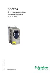
1.2 Components and interfaces<br />
Figure 1: Overview of connections<br />
CN1<br />
CN3<br />
CN4<br />
CN5<br />
(CN1) Mains connection (power stage supply)<br />
(CN2) Connection for<br />
• 24V controller supply<br />
• Safety function STO<br />
(CN3) Motor encoder connection (encoder 1)<br />
(CN4) Connection for PTO (Pulse Train Out)<br />
• ESIM (encoder simulation)<br />
(CN5) Connection for PTI (Pulse Train In)<br />
• Pulse/direction<br />
- or -<br />
• A/B encoder signals<br />
- or -<br />
• CW/CCW pulses<br />
(CN6) Inputs and outputs<br />
CN2<br />
• 2 analog reference value inputs ±10 V<br />
• 6 configurable digital inputs<br />
• 5 configurable digital outputs<br />
(CN7) Modbus (commissioning interface)<br />
(CN8) Connection for external braking resistor<br />
(CN9) DC bus connection<br />
(CN10) Motor phases connection<br />
(CN11) Motor holding brake connection<br />
CN6<br />
CN7<br />
CN8<br />
CN9<br />
CN10<br />
CN11<br />
14 AC servo drive<br />
0198441113761, V1.07, 01.2013
0198441113761, V1.07, 01.2013<br />
<strong>LXM32C</strong> 1 Introduction<br />
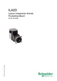
1.3 Nameplate<br />
The nameplate contains the following data:<br />
1<br />
2<br />
3<br />
4<br />
5<br />
Figure 2: Nameplate<br />
LXM32<br />
Input a.c. 3-phase Output<br />
50 / 60 Hz continuous max.<br />
380 V - 5.5 A 6 A - 1.8 kW 18 A<br />
480 V - 4.5 A<br />
6 A - 1.8 kW<br />
Multiple rated equipment, see instructions manual<br />
CN1, CN10:<br />
CN8:<br />
C<br />
Cu AWG10 75˚C<br />
Cu AWG12 75˚C<br />
KCC-RET-SEk-LXM32<br />
000000000000 Made in Indonesia<br />
18 A<br />
5.9 lb.in 0.67 N.m<br />
4.3 lb.in 0.49 N.m<br />
IP20<br />
US LISTED 91ZA<br />
IND.CONT.EQ<br />
E198280<br />
RS 02<br />
D.O.M<br />
dd.mm.yy<br />
(1) Product type, see type code<br />
(2) Power stage supply<br />
(3) Cable specifications and tightening torque<br />
(4) Certifications<br />
(5) Serial number<br />
(6) Output power<br />
(7) Degree of protection<br />
(8) Hardware version<br />
(9) Date of manufacture<br />
AC servo drive 15<br />
6<br />
7<br />
8<br />
9
1 Introduction <strong>LXM32C</strong><br />
1.4 Type code<br />
Product designation<br />
LXM - Lexium<br />
Product type<br />
32 - AC servo drive for one axis<br />
Interfaces<br />
C - Compact Drive with analog inputs and Pulse Train<br />
A - Advanced Drive with CANopen fieldbus<br />
M - Modular Drive<br />
Peak current<br />
U45 - 4.5Arms<br />
U60 - 6Arms<br />
U90 - 9Arms<br />
D12 - 12Arms<br />
D18 - 18Arms<br />
D30 - 30Arms<br />
D72 - 72Arms<br />
Power stage supply [Vac]<br />
M2 - 1~, 115/200/240Vac<br />
N4 - 3~, 208/400/480Vac 1)<br />
Further options<br />
1) 208Vac (3*200Vac ... 3*240Vac) DOM >10.05.2010, firmware version >V01.04.00<br />
LXM 32 C D18 M2 ∙ ∙ ∙ ∙<br />
If you have questions concerning the type code, contact your<br />
Schneider Electric sales office. Contact your machine vendor if you<br />
have questions concerning customized versions.<br />
Customized version: Position 12 of the type code is an "S". The subsequent<br />
number defines the customized version. Example: LXM32∙ ∙ ∙<br />
∙ ∙ ∙S123<br />
The device designation is shown on the nameplate.<br />
16 AC servo drive<br />
0198441113761, V1.07, 01.2013
0198441113761, V1.07, 01.2013<br />
<strong>LXM32C</strong> 2 Before you begin - safety information<br />
2 Before you begin - safety information<br />
2.1 Qualification of personnel<br />
2.2 Intended use<br />
2<br />
Only appropriately trained persons who are familiar with and understand<br />
the contents of this manual and all other pertinent product documentation<br />
are authorized to work on and with this product. In addition,<br />
these persons must have received safety training to recognize and<br />
avoid hazards involved. These persons must have sufficient technical<br />
training, knowledge and experience and be able to foresee and detect<br />
potential hazards that may be caused by using the product, by changing<br />
the settings and by the mechanical, electrical and electronic equipment<br />
of the entire system in which the product is used.<br />
All persons working on and with the product must be fully familiar with<br />
all applicable standards, directives, and accident prevention regulations<br />
when performing such work.<br />
This product is a drive for three-phase servo motors and intended for<br />
industrial use according to this manual.<br />
The product may only be used in compliance with all applicable safety<br />
regulations and directives, the specified requirements and the technical<br />
data.<br />
Prior to using the product, you must perform a risk assessment in view<br />
of the planned application. Based on the results, the appropriate<br />
safety measures must be implemented.<br />
Since the product is used as a component in an entire system, you<br />
must ensure the safety of persons by means of the design of this<br />
entire system (for example, machine design).<br />
Operate the product only with the specified cables and accessories.<br />
Use only genuine accessories and spare parts.<br />
The product must NEVER be operated in explosive atmospheres<br />
(hazardous locations, Ex areas).<br />
Any use other than the use explicitly permitted is prohibited and can<br />
result in hazards.<br />
Electrical equipment should be installed, operated, serviced, and<br />
maintained only by qualified personnel.<br />
AC servo drive 17
2 Before you begin - safety information <strong>LXM32C</strong><br />
2.3 Hazard categories<br />
Safety instructions to the user are highlighted by safety alert symbols<br />
in the manual. In addition, labels with symbols and/or instructions are<br />
attached to the product that alert you to potential hazards.<br />
Depending on the seriousness of the hazard, the safety instructions<br />
are divided into 4 hazard categories.<br />
DANGER<br />
DANGER indicates an imminently hazardous situation, which, if not<br />
avoided, will result in death or serious injury.<br />
WARNING<br />
WARNING indicates a potentially hazardous situation, which, if not<br />
avoided, can result in death, serious injury, or equipment damage.<br />
CAUTION<br />
CAUTION indicates a potentially hazardous situation, which, if not<br />
avoided, can result in injury or equipment damage.<br />
NOTICE<br />
NOTICE indicates a potentially hazardous situation, which, if not<br />
avoided, can result in equipment damage.<br />
18 AC servo drive<br />
0198441113761, V1.07, 01.2013
0198441113761, V1.07, 01.2013<br />
<strong>LXM32C</strong> 2 Before you begin - safety information<br />
2.4 Basic information<br />
DANGER<br />
HAZARD DUE TO ELECTRIC SHOCK, EXPLOSION OR ARC FLASH<br />
• Only appropriately trained persons who are familiar with and<br />
understand the contents of this manual and all other pertinent<br />
product documentation and who have received safety training to<br />
recognize and avoid hazards involved are authorized to work on<br />
and with this drive system. Installation, adjustment, repair and<br />
maintenance must be performed by qualified personnel.<br />
• The system integrator is responsible for compliance with all local<br />
and national electrical code requirements as well as all other<br />
applicable regulations with respect to grounding of all equipment.<br />
• Many components of the product, including the printed circuit<br />
board, operate with mains voltage. Do not touch. Use only electrically<br />
insulated tools.<br />
• Do not touch unshielded components or terminals with voltage<br />
present.<br />
• The motor generates voltage when the shaft is rotated. Prior to<br />
performing any type of work on the drive system, block the motor<br />
shaft to prevent rotation.<br />
• AC voltage can couple voltage to unused conductors in the motor<br />
cable. Insulate both ends of unused conductors of the motor<br />
cable.<br />
• Do not short across the DC bus terminals or the DC bus capacitors.<br />
• Before performing work on the drive system:<br />
- Disconnect all power, including external control power that<br />
may be present.<br />
- Place a "Do Not Turn On" label on all power switches.<br />
- Lock all power switches in the open position.<br />
- Wait 15 minutes to allow the DC bus capacitors to discharge.<br />
Measure the voltage on the DC bus as per chapter "DC bus<br />
voltage measurement" and verify the voltage is
2 Before you begin - safety information <strong>LXM32C</strong><br />
UNEXPECTED MOVEMENT<br />
WARNING<br />
Drive systems may perform unexpected movements because of<br />
incorrect wiring, incorrect settings, incorrect data or other errors.<br />
• Carefully install the wiring in accordance with the EMC requirements.<br />
• Do not operate the product with unknown settings or data.<br />
• Perform a comprehensive commissioning test.<br />
Failure to follow these instructions can result in death or serious<br />
injury.<br />
LOSS OF CONTROL<br />
WARNING<br />
• The designer of any control scheme must consider the potential<br />
failure modes of control paths and, for certain critical functions,<br />
provide a means to achieve a safe state during and after a path<br />
failure. Examples of critical control functions are emergency stop,<br />
overtravel stop, power outage and restart.<br />
• Separate or redundant control paths must be provided for critical<br />
functions.<br />
• System control paths may include communication links. Consideration<br />
must be given to the implication of unanticipated transmission<br />
delays or failures of the link.<br />
• Observe all accident prevention regulations and local safety<br />
guidelines. 1)<br />
• Each implementation of the product must be individually and thoroughly<br />
tested for proper operation before being placed into service.<br />
Failure to follow these instructions can result in death or serious<br />
injury.<br />
1) For USA: Additional information, refer to NEMA ICS 1.1 (latest edition), “Safety<br />
Guidelines for the Application, Installation, and Maintenance of Solid State Control”<br />
and to NEMA ICS 7.1 (latest edition), “Safety Standards for Construction and Guide<br />
for Selection, Installation and Operation of Adjustable-Speed Drive Systems”.<br />
20 AC servo drive<br />
0198441113761, V1.07, 01.2013
0198441113761, V1.07, 01.2013<br />
<strong>LXM32C</strong> 2 Before you begin - safety information<br />
2.5 DC bus voltage measurement<br />
2.6 Functional safety<br />
2.7 Standards and terminology<br />
Disconnect all power prior to starting work on the product.<br />
DANGER<br />
HAZARD OF ELECTRIC SHOCK, EXPLOSION OR ARC FLASH<br />
• Only appropriately trained persons who are familiar with and<br />
understand the safety instructions in the chapter "Before you<br />
begin - safety information" may perform the measurement.<br />
Failure to follow these instructions will result in death or serious<br />
injury.<br />
The DC bus voltage can exceed 800 Vdc. Use a properly rated voltage-sensing<br />
device for measuring. Procedure:<br />
▶ Disconnect the voltage supply to all connections.<br />
▶ Wait 15 minutes to allow the DC bus capacitors to discharge.<br />
▶ Measure the DC bus voltage between the DC bus terminals to verify<br />
that the voltage is
2 Before you begin - safety information <strong>LXM32C</strong><br />
22 AC servo drive<br />
0198441113761, V1.07, 01.2013
0198441113761, V1.07, 01.2013<br />
<strong>LXM32C</strong> 3 Technical Data<br />
3 Technical Data<br />
3.1 Ambient conditions<br />
Climatic environmental conditions<br />
transportation and storage<br />
Climatic environmental conditions<br />
operation<br />
3<br />
This chapter contains information on the ambient conditions and on<br />
the mechanical and electrical properties of the product family and the<br />
accessories.<br />
The environment during transportation and storage must be dry and<br />
free from dust.<br />
Temperature [°C] -25 ... 70<br />
The following relative humidity is permissible during transportation and<br />
storage:<br />
Relative humidity (non-condensing)<br />
[%]
3 Technical Data <strong>LXM32C</strong><br />
The installation altitude is defined as altitude above mean sea level.<br />
Installation altitude without derating<br />
Installation altitude if all of the following<br />
conditions are met:<br />
• Maximum ambient temperature<br />
45 °C<br />
• Reduction of the continuous<br />
power by 1 % per 100 m<br />
above 1000 m<br />
Installation altitude above mean<br />
sea level if all of the following conditions<br />
are met:<br />
• Maximum ambient temperature<br />
40 °C<br />
• Reduction of the continuous<br />
power by 1 % per 100 m<br />
above 1000 m<br />
• Overvoltages of the supply<br />
mains limited to overvoltage<br />
category II as per IEC 60664-1<br />
• No IT mains<br />
[m]
0198441113761, V1.07, 01.2013<br />
<strong>LXM32C</strong> 3 Technical Data<br />
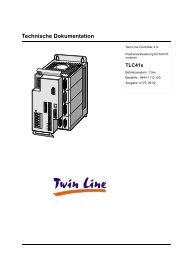
3.2 Mechanical data<br />
3.2.1 Dimensional drawings<br />
Ø5.5<br />
Ø10<br />
Ø5.5<br />
e<br />
B<br />
f<br />
F<br />
H<br />
Figure 3: Dimensional drawing<br />
Ø5.5<br />
2x<br />
Ø10<br />
2x Ø5.5<br />
e<br />
E<br />
B<br />
f<br />
F<br />
H<br />
Figure 4: Dimensional drawing<br />
AC servo drive 25<br />
T<br />
T<br />
X<br />
X<br />
a h<br />
c<br />
a h<br />
c<br />
Y Z<br />
Y Z
3 Technical Data <strong>LXM32C</strong><br />
Mass<br />
LXM32∙... U45∙ ∙<br />
U60∙ ∙<br />
U90∙ ∙<br />
D12∙ ∙<br />
D18∙ ∙<br />
D30M2<br />
D30N4 D72∙ ∙<br />
Figure Figure 3 Figure 3 Figure 4 Figure 4<br />
B [mm] 48 ±1 48 ±1 68 ±1 108 ±1<br />
T [mm] 225 225 225 225<br />
H [mm] 270 270 270 274<br />
e [mm] 24 24 13 13<br />
E [mm] - - 42 82<br />
F [mm] 258 258 258 258<br />
f [mm] 7.5 7.5 7.5 7.5<br />
a [mm] 20 20 20 24<br />
h [mm] 230 230 230 230<br />
c [mm] 20 20 20 20<br />
X required free space [mm] 60 60 60 60<br />
Y required free space [mm] 100 100 100 100<br />
Z required free space [mm] 100 100 100 100<br />
Type of cooling Convection<br />
1)<br />
1) >1 m/s<br />
Fan<br />
40 mm<br />
Fan<br />
60 mm<br />
Fan<br />
80 mm<br />
The connection cables of the devices are routed to the top and to the<br />
bottom. The following distances are required in order to enable sufficient<br />
air circulation and cable installation without bends:<br />
• At least 100 mm of free space is required above the device.<br />
• At least 100 mm of free space is required below the device.<br />
• At least 60 mm of free space is required in front of the device. The<br />
controls must be accessible.<br />
LXM32∙... U45∙ ∙ U60∙ ∙<br />
U90∙ ∙<br />
D12∙ ∙<br />
D18M2<br />
D18N4<br />
D30M2<br />
D30N4 D72N4<br />
Mass kg 1.6 1.7 1.8 2.0 2.6 4.7<br />
26 AC servo drive<br />
0198441113761, V1.07, 01.2013
0198441113761, V1.07, 01.2013<br />
<strong>LXM32C</strong> 3 Technical Data<br />
3.3 Electrical Data<br />
3.3.1 Power stage<br />
Mains voltage: range and tolerance<br />
Type of mains (type of grounding)<br />
Inrush current and leakage current<br />
The products are intended for industrial use and may only be operated<br />
with a permanently installed connection.<br />
115/230 Vac single-phase [Vac] 100 -15% ... 120 +10%<br />
200 -15% ... 240 +10%<br />
208/400/480 Vac three-phase 1) [Vac] 200 -15% ... 240 +10%<br />
380 -15% ... 480 +10%<br />
Frequency [Hz] 50 -5% ... 60 +5%<br />
1) 208Vac (3*200Vac ... 3*240Vac) DOM >10.05.2010, firmware version >V01.04.00<br />
Transient overvoltages Overvoltage category III 1)<br />
Rated voltage to ground [Vac] 300<br />
1) Depends on installation altitude, see chapter "3.1 Ambient conditions"<br />
TT mains, TN mains Permitted<br />
IT mains Devices RS 00, RS 01: Not approved<br />
Mains with grounded line conductor Not approved<br />
Devices RS 02 and higher: Approved<br />
1)<br />
1) Depending on installation altitude, see chapter "3.1 Ambient conditions"<br />
Inrush current [A]
3 Technical Data <strong>LXM32C</strong><br />
Peak output current for 1 second The device can provide the peak output current for 1 second. If the<br />
peak output current flows when the motor is at a standstill, the higher<br />
load on a single semiconductor switch causes the current limitation to<br />
become active earlier than when the motor moves.<br />
PWM frequency power stage The PWM frequency of the power stage is set to a fixed value.<br />
PWM frequency power stage [kHz] 8<br />
Approved motors The following motors can be connected to this device family: BMH,<br />
BSH.<br />
When selecting, consider the type and amount of the mains voltage<br />
and the motor inductance.<br />
Inquire for other motors.<br />
Inductance of motor The permissible minimum inductance and the maximum permissible<br />
inductance of the motor to be connected depend on the device type<br />
and the nominal mains voltage. See the tables on pages 29 to 33<br />
for the values.<br />
The specified minimum inductance value limits the current ripple of the<br />
peak output current. If the inductance value of the connected motor is<br />
less than the specified minimum inductance value, this may adversely<br />
affect current control and trigger motor phase current monitoring.<br />
28 AC servo drive<br />
0198441113761, V1.07, 01.2013
0198441113761, V1.07, 01.2013<br />
<strong>LXM32C</strong> 3 Technical Data<br />
3.3.1.1 Data for single-phase devices at 115Vac<br />
LXM32∙... U45M2∙... U90M2∙... D18M2∙... D30M2∙...<br />
Nominal voltage [V] 115 (1 ∼) 115 (1 ∼) 115 (1 ∼) 115 (1 ∼)<br />
Inrush current limitation [A] 1.7 3.5 8 16<br />
Maximum fuse to be connected upstream<br />
1)<br />
[A] 25 25 25 25<br />
Short-circuit current rating (SCCR) [kA] 5 5 5 5<br />
Continuous output current [Arms] 1.5 3 6 10<br />
Peak output current (for 1 s) [Arms] 3 6 10 15<br />
Minimum inductance motor (phase/<br />
phase)<br />
Values without mains reactor<br />
[mH] 5.5 3 1.4 0.8<br />
Nominal power 2) [kW] 0.15 0.3 0.5 0.8<br />
Input current at nominal power and nominal<br />
voltage 2)<br />
Total harmonic distortion THD of the<br />
input current 2)<br />
[Arms] 2.9 5.4 8.5 12.9<br />
[%] 173 159 147 135<br />
Power dissipation 3) [W] 7 15 28 33<br />
Maximum inrush current 4) [A] 111 161 203 231<br />
Time for maximum inrush current [ms] 0.8 1.0 1.2 1.4<br />
Values with mains reactor<br />
Mains reactor [mH] 5 2 2 2<br />
Nominal power [kW] 0.2 0.4 0.8 0.8<br />
Input current at nominal power and nominal<br />
voltage<br />
Total harmonic distortion THD of the<br />
input current<br />
[Arms] 2.6 5.2 9.9 9.9<br />
[%] 85 90 74 72<br />
Power dissipation 3) [W] 8 16 32 33<br />
Maximum inrush current 4) [A] 22 48 56 61<br />
Time for maximum inrush current [ms] 3.3 3.1 3.5 3.7<br />
1) Fuse: Circuit breakers with B or C characteristic; See "3.4 Conditions for UL 508C and CSA" for UL and CSA; Lower Ratings are<br />
permissible; The fuse must be rated in such a way that the fuse does not trip at the specified input current.<br />
2) At a mains impedance corresponding to a short-circuit current of the supply mains of 1 kA<br />
3) Condition: internal braking resistor not active; value at nominal current, nominal voltage and nominal power; value approximately<br />
proportional with output current<br />
4) Extreme case, off/on pulse before the inrush current limitation responds, see next line for maximum time<br />
AC servo drive 29
3 Technical Data <strong>LXM32C</strong><br />
3.3.1.2 Data for single-phase devices at 230Vac<br />
LXM32∙... U45M2∙... U90M2∙... D18M2∙... D30M2∙...<br />
Nominal voltage [V] 230 (1 ∼) 230 (1 ∼) 230 (1 ∼) 230 (1 ∼)<br />
Inrush current limitation [A] 3.5 6.9 16 33<br />
Maximum fuse to be connected upstream<br />
1)<br />
[A] 25 25 25 25<br />
Short-circuit current rating (SCCR) [kA] 5 5 5 5<br />
Continuous output current [Arms] 1.5 3 6 10<br />
Peak output current (for 1 s) [Arms] 4.5 9 18 30<br />
Minimum inductance motor (phase/<br />
phase)<br />
Values without mains reactor<br />
[mH] 5.5 3 1.4 0.8<br />
Nominal power 2) [kW] 0.3 0.5 1.0 1.6<br />
Input current at nominal power and nominal<br />
voltage 2)<br />
Total harmonic distortion THD of the<br />
input current 2)<br />
[Arms] 2.9 4.5 8.4 12.7<br />
[%] 181 166 148 135<br />
Power dissipation 3) [W] 10 18 34 38<br />
Maximum inrush current 4) [A] 142 197 240 270<br />
Time for maximum inrush current [ms] 1.1 1.5 1.8 2.1<br />
Values with mains reactor<br />
Mains reactor [mH] 5 2 2 2<br />
Nominal power [kW] 0.5 0.9 1.6 2.2<br />
Input current at nominal power and nominal<br />
voltage<br />
Total harmonic distortion THD of the<br />
input current<br />
[Arms] 3.4 6.3 10.6 14.1<br />
[%] 100 107 93 86<br />
Power dissipation 3) [W] 11 20 38 42<br />
Maximum inrush current 4) [A] 42 90 106 116<br />
Time for maximum inrush current [ms] 3.5 3.2 3.6 4.0<br />
1) Fuse: Circuit breakers with B or C characteristic; See "3.4 Conditions for UL 508C and CSA" for UL and CSA; Lower Ratings are<br />
permissible; The fuse must be rated in such a way that the fuse does not trip at the specified input current.<br />
2) At a mains impedance corresponding to a short-circuit current of the supply mains of 1 kA<br />
3) Condition: internal braking resistor not active; value at nominal current, nominal voltage and nominal power; value approximately<br />
proportional with output current<br />
4) Extreme case, off/on pulse before the inrush current limitation responds, see next line for maximum time<br />
30 AC servo drive<br />
0198441113761, V1.07, 01.2013
0198441113761, V1.07, 01.2013<br />
<strong>LXM32C</strong> 3 Technical Data<br />
3.3.1.3 Data for three-phase devices at 208Vac 1<br />
LXM32∙... U60N4∙... D12N4∙... D18N4∙... D30N4∙... D72N4∙...<br />
Nominal voltage [V] 208 (3 ∼) 208 (3 ∼) 208 (3 ∼) 208 (3 ∼) 208 (3 ∼)<br />
Inrush current limitation [A] 2.2 4.9 10 10 29<br />
Maximum fuse to be connected upstream<br />
1)<br />
[A] 30/32 30/32 30/32 30/32 30/32<br />
Short-circuit current rating (SCCR) [kA] 5 5 5 5 5<br />
Continuous output current [Arms] 1.5 3 6 10 24<br />
Peak output current (for 1 s) [Arms] 6 12 18 30 72<br />
Minimum inductance motor (phase/<br />
phase)<br />
Values without mains reactor<br />
[mH] 8.5 4.5 3 1.7 0.7<br />
Nominal power [kW] 0.35 0.7 1.2 2.0 5<br />
Input current at nominal power and nominal<br />
voltage<br />
Total harmonic distortion THD of the<br />
input current<br />
Power dissipation without mains reactor<br />
2)<br />
[Arms] 1.8 3.6 6.2 9.8 21.9<br />
[%] 132 136 140 128 106<br />
[W] 13 26 48 81 204<br />
Maximum inrush current 3) [A] 60 180 276 341 500<br />
Time for maximum inrush current [ms] 0.5 0.7 0.9 1.1 1.5<br />
Values with mains reactor<br />
Mains reactor [mH] 2 2 1 1 1<br />
Nominal power [kW] 0.4 0.8 1.5 2.6 6.5<br />
Input current at nominal power and nominal<br />
voltage<br />
Total harmonic distortion THD of the<br />
input current<br />
[Arms] 1.7 3.1 6.0 9.2 21.1<br />
[%] 97 79 78 59 34<br />
Power dissipation 2) [W] 13 27 51 86 218<br />
Maximum inrush current 3) [A] 19 55 104 126 155<br />
Time for maximum inrush current [ms] 1.9 2.6 2.6 3.0 3.6<br />
1) Fuses: Circuit breakers with B or C characteristic; See "3.4 Conditions for UL 508C and CSA" for UL and CSA; Specification<br />
30/32A: The maximum permissible value for UL is 30A; Lower ratings are permissible; The fuse must be rated in such a way that<br />
the fuse does not trip at the specified input current.<br />
2) Condition: internal braking resistor not active; value at nominal current, nominal voltage and nominal power; value approximately<br />
proportional with output current<br />
3) Extreme case, off/on pulse before the inrush current limitation responds, see next line for maximum time<br />
1. 208Vac (3*200Vac ... 3*240Vac) DOM >10.05.2010, firmware version >V01.04.00<br />
AC servo drive 31
3 Technical Data <strong>LXM32C</strong><br />
3.3.1.4 Data for three-phase devices at 400Vac<br />
LXM32∙... U60N4∙... D12N4∙... D18N4∙... D30N4∙... D72N4∙...<br />
Nominal voltage [V] 400 (3 ∼) 400 (3 ∼) 400 (3 ∼) 400 (3 ∼) 400 (3 ∼)<br />
Inrush current limitation [A] 4.3 9.4 19 19 57<br />
Maximum fuse to be connected upstream<br />
1)<br />
[A] 30/32 30/32 30/32 30/32 30/32<br />
Short-circuit current rating (SCCR) [kA] 5 5 5 5 5<br />
Continuous output current [Arms] 1.5 3 6 10 24<br />
Peak output current (for 1 s) [Arms] 6 12 18 30 72<br />
Minimum inductance motor (phase/<br />
phase)<br />
Values without mains reactor<br />
[mH] 8.5 4.5 3 1.7 0.7<br />
Nominal power [kW] 0.4 0.9 1.8 3.0 7<br />
Input current at nominal power and nominal<br />
voltage<br />
Total harmonic distortion THD of the<br />
input current<br />
[Arms] 1.4 2.9 5.2 8.3 17.3<br />
[%] 191 177 161 148 126<br />
Power dissipation 2) [W] 17 37 68 115 283<br />
Maximum inrush current 3) [A] 90 131 201 248 359<br />
Time for maximum inrush current [ms] 0.5 0.7 0.9 1.1 1.4<br />
Values with mains reactor<br />
Mains reactor [mH] 2 2 1 1 1<br />
Nominal power [kW] 0.8 1.6 3.3 5.6 13<br />
Input current at nominal power and nominal<br />
voltage<br />
Total harmonic distortion THD of the<br />
input current<br />
[Arms] 1.8 3.4 6.9 11.1 22.5<br />
[%] 108 90 90 77 45<br />
Power dissipation 2) [W] 19 40 74 125 308<br />
Maximum inrush current 3) [A] 28 36 75 87 112<br />
Time for maximum inrush current [ms] 1.9 2.3 2.3 2.6 3.0<br />
1) Fuses: Circuit breakers with B or C characteristic; See "3.4 Conditions for UL 508C and CSA" for UL and CSA; Specification<br />
30/32A: The maximum permissible value for UL is 30A; Lower ratings are permissible; The fuse must be rated in such a way that<br />
the fuse does not trip at the specified input current.<br />
2) Condition: internal braking resistor not active; value at nominal current, nominal voltage and nominal power; value approximately<br />
proportional with output current<br />
3) Extreme case, off/on pulse before the inrush current limitation responds, see next line for maximum time<br />
32 AC servo drive<br />
0198441113761, V1.07, 01.2013
0198441113761, V1.07, 01.2013<br />
<strong>LXM32C</strong> 3 Technical Data<br />
3.3.1.5 Data for three-phase devices at 480Vac<br />
LXM32∙... U60N4∙... D12N4∙... D18N4∙... D30N4∙... D72N4∙...<br />
Nominal voltage [V] 480 (3 ∼) 480 (3 ∼) 480 (3 ∼) 480 (3 ∼) 480 (3 ∼)<br />
Inrush current limitation [A] 5.1 11.3 23 23 68<br />
Maximum fuse to be connected upstream<br />
1)<br />
[A] 30/32 30/32 30/32 30/32 30/32<br />
Short-circuit current rating (SCCR) [kA] 5 5 5 5 5<br />
Continuous output current [Arms] 1.5 3 6 10 24<br />
Peak output current (for 1 s) [Arms] 6 12 18 30 72<br />
Minimum inductance motor (phase/<br />
phase)<br />
Values without mains reactor<br />
[mH] 8.5 4.5 3 1.7 0.7<br />
Nominal power [kW] 0.4 0.9 1.8 3.0 7<br />
Input current at nominal power and nominal<br />
voltage<br />
Total harmonic distortion THD of the<br />
input current<br />
[Arms] 1.2 2.4 4.5 7.0 14.6<br />
[%] 201 182 165 152 129<br />
Power dissipation 2) [W] 20 42 76 129 315<br />
Maximum inrush current 3) [A] 129 188 286 350 504<br />
Time for maximum inrush current [ms] 0.6 0.7 1.0 1.2 1.6<br />
Values with mains reactor<br />
Mains reactor [mH] 2 2 1 1 1<br />
Nominal power [kW] 0.8 1.6 3.3 5.6 13<br />
Input current at nominal power and nominal<br />
voltage<br />
Total harmonic distortion THD of the<br />
input current<br />
[Arms] 1.6 2.9 6.0 9.6 19.5<br />
[%] 116 98 98 85 55<br />
Power dissipation 2) [W] 21 44 82 137 341<br />
Maximum inrush current 3) [A] 43 57 116 137 177<br />
Time for maximum inrush current [ms] 1.9 2.4 2.4 2.7 3.2<br />
1) Fuses: Circuit breakers with B or C characteristic; See "3.4 Conditions for UL 508C and CSA" for UL and CSA; Specification<br />
30/32A: The maximum permissible value for UL is 30A; Lower ratings are permissible; The fuse must be rated in such a way that<br />
the fuse does not trip at the specified input current.<br />
2) Condition: internal braking resistor not active; value at nominal current, nominal voltage and nominal power; value approximately<br />
proportional with output current<br />
3) Extreme case, off/on pulse before the inrush current limitation responds, see next line for maximum time<br />
AC servo drive 33
3 Technical Data <strong>LXM32C</strong><br />
3.3.1.6 Peak output currents<br />
LXM32 ... U45M2<br />
LXM32 ... D18N4<br />
I [%]<br />
U30M2<br />
D18M2<br />
D30M2<br />
230V<br />
D30N4<br />
D72N4<br />
300<br />
200<br />
100<br />
0<br />
0 1 2 3 4 5 10 15 20 25 30<br />
1<br />
2<br />
t [s]<br />
Figure 5: Peak output current over time (with reference to the continuous output<br />
current)<br />
LXM32 ... U60N4<br />
D12N4<br />
I [%]<br />
400<br />
300<br />
200<br />
100<br />
0<br />
0 1 2 3 4 5 10 15 20 25 30<br />
1<br />
2<br />
t [s]<br />
Figure 6: Peak output current over time (with reference to the continuous output<br />
current)<br />
(1) With hardware version ≥RS03<br />
(2) With hardware version
0198441113761, V1.07, 01.2013<br />
<strong>LXM32C</strong> 3 Technical Data<br />
3.3.1.7 DC bus data for single-phase devices<br />
LXM32∙... (1 ∼) U45M2 U90M2 D18M2 D30M2<br />
Nominal voltage (1 ∼) [V] 115 230 115 230 115 230 115 230<br />
Nominal voltage DC bus [V] 163 325 163 325 163 325 163 325<br />
Undervoltage limit [V] 55 130 55 130 55 130 55 130<br />
Voltage limit: activation of Quick Stop [V] 60 140 60 140 60 140 60 140<br />
Overvoltage limit [V] 450 450 450 450 450 450 450 450<br />
Maximum continuous power via DC bus [kW] 0.2 0.5 0.4 0.9 0.8 1.6 0.8 2.2<br />
Maximum continuous current via DC bus [A] 1.5 1.5 3.2 3.2 6.0 6.0 10.0 10.0<br />
3.3.1.8 DC bus data for three-phase devices<br />
LXM32∙... (3 ∼) U60N4 D12N4 D18N4 D30N4 D72N4<br />
Nominal voltage (3 ∼) 1) [V] 208 208 208 208 208<br />
Nominal voltage DC bus [V] 294 294 294 294 294<br />
Undervoltage limit [V] 150 150 150 150 150<br />
Voltage limit: activation of Quick Stop [V] 160 160 160 160 160<br />
Overvoltage limit [V] 820 820 820 820 820<br />
Maximum continuous power via DC bus [kW] 0.4 0.8 1.7 2.8 6.5<br />
Maximum continuous current via DC bus [A] 1.5 3.2 6.0 10.0 22.0<br />
1) 208Vac (3*200Vac ... 3*240Vac) DOM >10.05.2010, firmware version >V01.04.00<br />
LXM32∙... (3 ∼) U60N4 D12N4 D18N4 D30N4 D72N4<br />
Nominal voltage (3 ∼) [V] 400 480 400 480 400 480 400 480 400 480<br />
Nominal voltage DC bus [V] 566 679 566 679 566 679 566 679 566 679<br />
Undervoltage limit [V] 350 350 350 350 350 350 350 350 350 350<br />
Voltage limit: activation of Quick Stop [V] 360 360 360 360 360 360 360 360 360 360<br />
Overvoltage limit [V] 820 820 820 820 820 820 820 820 820 820<br />
Maximum continuous power via DC bus [kW] 0.8 0.8 1.6 1.6 3.3 3.3 5.6 5.6 13.0 13.0<br />
Maximum continuous current via DC bus [A] 1.5 1.5 3.2 3.2 6.0 6.0 10.0 10.0 22.0 22.0<br />
AC servo drive 35
3 Technical Data <strong>LXM32C</strong><br />
3.3.2 Controller supply voltage 24V<br />
Controller supply in the case of<br />
motor with holding brake<br />
29<br />
28<br />
27<br />
26<br />
25<br />
24<br />
24V supply The +24VDC controller supply voltage must meet the requirements of<br />
IEC 61131-2 (PELV standard power supply unit):<br />
Input voltage [Vdc] 24 V -15% / +20% 1)<br />
Input current (without load) [A] ≤1 2)<br />
Residual ripple
0198441113761, V1.07, 01.2013<br />
<strong>LXM32C</strong> 3 Technical Data<br />
3.3.3 Signals<br />
Analog input signals<br />
The digital inputs and outputs of this product can be wired for logic<br />
type 1 or logic type 2.<br />
1 2<br />
+24V<br />
0V<br />
Figure 8: Logic type<br />
DQ_COM<br />
DQ0,DQ1,...<br />
DI0,DI1,...<br />
DI_COM<br />
Logic type Active state<br />
+24V<br />
(1) Logic type 1 Output supplies current (source output)<br />
Current flows to the input<br />
(2) Logic type 2 Output draws current (sink output)<br />
Current flows from the input<br />
0V<br />
DQ_COM<br />
DQ0,DQ1,...<br />
DI0,DI1,...<br />
DI_COM<br />
Signal inputs are protected against reverse polarity, outputs are shortcircuit<br />
protected. The inputs and outputs are galvanically isolated.<br />
Voltage range of differential input<br />
circuit<br />
[V] -10 ... +10<br />
Input resistance, typical [kΩ] 20<br />
Resolution [bit] 14<br />
Sampling period [ms] 0.25<br />
Digital input signals 24 V When wired as logic type 1, the levels of the opto-isolated inputs DI∙<br />
comply with IEC 61131-2, type 1.<br />
Input signals safety function STO<br />
Level 0 with logic type 1 (Ulow) [Vdc] -3 ... +5<br />
Level 1 with logic type 1 (Uhigh) [Vdc] +15 ... +30<br />
Input current (typical) [mA] 5<br />
Debounce time 1) [ms] 1.5<br />
1) Adjustable via parameter (sampling period 250µs)<br />
Level 0 with logic type 1 (Ulow) [Vdc] -3 ... +5<br />
Level 1 with logic type 1 (Uhigh) [Vdc] +15 ... +30<br />
Input current (typical) [mA] 5<br />
Debounce time STO_A and STO_B [ms] >1<br />
Detection of signal differences<br />
between STO_A and STO_B<br />
Response time of safety function<br />
STO<br />
[s] >1<br />
[ms] ≤10<br />
AC servo drive 37
3 Technical Data <strong>LXM32C</strong><br />
24 V output signals The levels of the digital 24 V output signals DQ∙ comply with<br />
IEC 61131-2.<br />
Output voltage [V] ≤30<br />
Maximum switching current [mA] ≤100<br />
Voltage drop at 100 mA load [V] ≤3<br />
Holding brake output CN11 The 24 Vdc holding brake of the BMH motor or the BSH motor can be<br />
connected to the output CN11. Data of output CN11:<br />
Output voltage 1) [V] Voltage at controller supply CN2<br />
minus 0.8 V<br />
Maximum switching current [A] 1.7<br />
Energy inductive load 2) [Ws] 1.5<br />
1) See "3.3.2 Controller supply voltage 24V"<br />
2) Time between switch off procedures: > 1 s<br />
Encoder signals The encoder signals comply with the Stegmann Hiperface specification.<br />
Output voltage for encoder +10 V / 100 mA<br />
SIN/COS input signal voltage<br />
range<br />
Input resistance [Ω] 120<br />
1 Vpp with 2.5 V offset,<br />
0.5 Vpp at 100 kHz<br />
The output voltage is short-circuit protected and overload protected.<br />
Transmission via RS485, asynchronous, half-duplex<br />
38 AC servo drive<br />
0198441113761, V1.07, 01.2013
0198441113761, V1.07, 01.2013<br />
<strong>LXM32C</strong> 3 Technical Data<br />
3.3.3.1 Output PTO (CN4)<br />
5 V signals are available at the PTO (Pulse Train Out, CN4) output.<br />
Depending on parameter PTO_mode, these signals are ESIM signals<br />
(encoder simulation) or directly transmitted PTI input signals (P/D signals,<br />
A/B signals, CW/CCW signals). The PTO output signals can be<br />
used as PTI input signals for another device. The PTO output signals<br />
have 5 V, even if the PTI input signal is a 24 V signal.<br />
The signal level corresponds to RS422. Due to the input current of the<br />
optocoupler in the input circuit, a parallel connection of a driver output<br />
to several devices is not permitted.<br />
The basic resolution of the encoder simulation at quadruple resolution<br />
is 4096 increments per revolution in the case of rotary motors.<br />
A<br />
B<br />
I<br />
1<br />
0<br />
1<br />
0<br />
1<br />
0<br />
+ -<br />
..7 8 9 ... 12 13 14 15 14 13 ... 9 8..<br />
Figure 9: Time chart with A, B and index pulse signal, counting forwards and<br />
backwards<br />
Output signal PTO The PTO output signals comply with the RS422 interface specification.<br />
Logic level As per RS422 1)<br />
Output frequency per signal [kHz] ≤500<br />
Motor increments per second [Inc/s<br />
]<br />
≤1.6 * 10 6<br />
1) Due to the input current of the optocoupler in the input circuit, a parallel connection<br />
of a driver output to several devices is not permitted.<br />
NOTE: The device connected to the PTO output must be able to process<br />
the specified motor increments per second. Even at low velocities,<br />
(medium PTO frequency in the kHz range), edges may change at up<br />
to 1.6 MHz.<br />
AC servo drive 39
3 Technical Data <strong>LXM32C</strong><br />
3.3.3.2 Input PTI (CN5)<br />
Input circuit and selection of<br />
method<br />
Input circuit RS422<br />
Figure 10 left<br />
Minimum input frequency with method<br />
position synchronization<br />
Minimum input frequency with method<br />
velocity synchronization<br />
UNEXPECTED MOVEMENT<br />
WARNING<br />
Incorrect or interfered signals as reference values can cause unexpected<br />
movements.<br />
• Use shielded twisted-pair cables.<br />
• If possible, operate the interface with push-pull signals.<br />
• Do not use signals without push-pull in critical applications or in<br />
environments subject to interference.<br />
• Do not use signals without push-pull in the case of cable lengths<br />
of more than 3 m and limit the frequency to 50 kHz.<br />
Failure to follow these instructions can result in death, serious<br />
injury or equipment damage.<br />
5 V signals or 24 V signals can be connected to the PTI (Pulse Train<br />
In) input.<br />
The following signals can be connected:<br />
• A/B signals (ENC_A/ENC_B)<br />
• P/D signals (PULSE/DIR)<br />
• CW/CCW signals (CW/CCW)<br />
See also chapter "6.2.11 Connection PTI (CN5, Pulse Train In)", page<br />
115.<br />
The input circuit and the selected method affect the maximum permissible<br />
input frequency and the maximum permissible line length:<br />
Push pull<br />
Figure 10 center<br />
0 Hz 0 Hz 0 Hz<br />
100 Hz 100 Hz 100 Hz<br />
Open collector<br />
Figure 10 right<br />
Maximum input frequency 1 MHz 0.2 MHz 0.01 MHz<br />
Maximum line length 100 m 10 m 1 m<br />
40 AC servo drive<br />
0198441113761, V1.07, 01.2013
0198441113761, V1.07, 01.2013<br />
<strong>LXM32C</strong> 3 Technical Data<br />
5Vdc<br />
24Vdc<br />
A<br />
B<br />
C<br />
RS422 PushPull<br />
5VDC<br />
24VDC<br />
PushPull<br />
Figure 10: Signal input circuits: RS422, Push Pull and Open Collector<br />
5VDC A<br />
24VDC<br />
Input Pin 1) RS422 2) 5V 24V<br />
A<br />
B<br />
C<br />
A<br />
B<br />
C<br />
B<br />
C<br />
A<br />
B<br />
C<br />
OpenCollector<br />
OpenCollector<br />
A Pin 7 Reserved Reserved PULSE(24)<br />
ENC_A(24)<br />
CW(24)<br />
Pin 8 Reserved Reserved DIR(24)<br />
ENC_B(24)<br />
CCW(24<br />
B Pin 1 PULSE(5)<br />
ENC_A(5)<br />
CW(5)<br />
Pin4 DIR(5)<br />
ENC_B(5)<br />
CCW(5)<br />
C Pin 2 PULSE<br />
ENC_A<br />
CW<br />
Pin 5 DIR<br />
ENC_B<br />
CCW<br />
PULSE(5)<br />
ENC_A(5)<br />
CW(5)<br />
DIR(5)<br />
ENC_B(5)<br />
CCW(5)<br />
PULSE<br />
ENC_A<br />
CW<br />
DIR<br />
ENC_B<br />
CCW<br />
Reserved<br />
Reserved<br />
PULSE<br />
ENC_A<br />
CW<br />
DIR<br />
ENC_B<br />
CCW<br />
1) Observe the different pairing in the case of twisted pair:<br />
Pin 1 / pin 2 and pin 4 / pin 5 for RS422 and 5V;<br />
pin 7 / pin 2 and pin 8 / pin 5 for 24V<br />
2) Due to the input current of the optocoupler in the input circuit, a parallel connection of a driver output to several devices is not permitted.<br />
AC servo drive 41
3 Technical Data <strong>LXM32C</strong><br />
Function A/B signals External A/B signals can be supplied via the PTI input as reference<br />
values in operating mode Electronic Gear.<br />
Signal Value Function<br />
Signal A before signal B Movement in positive<br />
direction<br />
Signal B before signal A Movement in negative<br />
direction<br />
1<br />
A<br />
0<br />
1<br />
B<br />
0<br />
2 2<br />
3<br />
3<br />
1<br />
..7 8 9 ... 12 13 14 15 14 13 ... 9 8..<br />
+ -<br />
Figure 11: Time chart with A/B signal, counting forwards and backwards<br />
Times for pulse/direction Minimum value<br />
Cycle duration A, B 1 μs (1)<br />
Pulse duration 0.4 μs (2)<br />
Lead time (A, B) 200 ns (3)<br />
42 AC servo drive<br />
0198441113761, V1.07, 01.2013
0198441113761, V1.07, 01.2013<br />
<strong>LXM32C</strong> 3 Technical Data<br />
Function P/D External P/D signals can be supplied via the PTI input as reference<br />
values in the operating mode Electronic Gear.<br />
The motor performs a movement in the case of a rising edge of the<br />
PULSE signal. The direction is controlled with the DIR signal.<br />
Signal Value Function<br />
PULSE 0 -> 1 Motor movement<br />
DIR 0 / open Positive direction<br />
1<br />
PULSE<br />
0<br />
1<br />
DIR<br />
0<br />
2<br />
2<br />
1<br />
3<br />
+ + - +<br />
Figure 12: Time chart with pulse/direction signal<br />
Times for pulse/direction Minimum value<br />
Cycle duration (pulse) 1 μs (1)<br />
Pulse duration (pulse) 0.4 μs (2)<br />
Lead time (Dir-Pulse) 0 μs (3)<br />
Hold time (Pulse-Dir) 0.4 μs (4)<br />
AC servo drive 43<br />
2<br />
4
3 Technical Data <strong>LXM32C</strong><br />
Function CW/CCW External CW/CCW signals can be supplied via the PTI input as reference<br />
values in operating mode Electronic Gear.<br />
The motor performs a movement in positive direction the case of a rising<br />
edge of the CW signal. The motor performs a movement in negative<br />
direction the case of a rising edge of the CCW signal.<br />
Signal Value Function<br />
CW 0 -> 1 Movement in positive<br />
direction<br />
CCW 0 -> 1 Movement in negative<br />
direction<br />
CW<br />
CCW<br />
1<br />
0<br />
1<br />
0<br />
2<br />
Figure 13: Time chart with "CW/CCW"<br />
2<br />
1<br />
3<br />
2 2<br />
+ + - -<br />
Times for pulse/direction Minimum value<br />
Cycle duration CW, CCW 1 μs (1)<br />
Pulse duration 0.4 μs (2)<br />
Lead time (CW-CCW,<br />
CCW-CW)<br />
0 μs (3)<br />
44 AC servo drive<br />
0198441113761, V1.07, 01.2013
0198441113761, V1.07, 01.2013<br />
<strong>LXM32C</strong> 3 Technical Data<br />
3.3.4 Functional safety<br />
Data for maintenance plan and<br />
safety calculations<br />
The safety function must be requested and tested at regular intervals.<br />
The interval depends on the hazard and risk analysis of the total system.<br />
The minimum interval is 1 year (high demand mode as per<br />
IEC 61508).<br />
Use the following data of the safety function STO for your maintenance<br />
plan and the safety calculations:<br />
Lifetime of the safety function<br />
STO (IEC 61508) 1)<br />
SFF (IEC 61508)<br />
Safe Failure Fraction<br />
HFT (IEC 61508)<br />
Hardware Fault Tolerance<br />
Type A subsystem<br />
Safety integrity level<br />
IEC 61508<br />
IEC 62061<br />
PFH (IEC 61508)<br />
Probability of Dangerous Hardware<br />
Failure per Hour<br />
PL (ISO 13849-1)<br />
Performance Level<br />
MTTFd (ISO 13849-1)<br />
Mean Time to Dangerous Failure<br />
DC (ISO 13849-1)<br />
Diagnostic Coverage<br />
Years 20<br />
[%] 80<br />
[1/h]<br />
(FIT)<br />
1<br />
SIL3<br />
SILCL3<br />
1*10 -9<br />
(1)<br />
Years 1400<br />
[%] 90<br />
1) See chapter "13.2.1 Lifetime safety function STO".<br />
e (category 3)<br />
Contact your local sales office for additional data, if required.<br />
AC servo drive 45
3 Technical Data <strong>LXM32C</strong><br />
3.3.5 Braking resistor<br />
The device has an internal braking resistor. If the internal braking<br />
resistor is insufficient for the dynamics of the application, one or more<br />
external braking resistors must be used.<br />
The resistance values for external braking resistors must not be below<br />
the specified minimum resistance. If an external braking resistor is<br />
activated by means of the appropriate parameter, the internal braking<br />
resistor is deactivated.<br />
Further information on the subject Page<br />
Rating the external braking resistor 71<br />
Mounting the external braking resistor (accessory) 89<br />
Electrical installation of the braking resistor (accessory) 71<br />
Setting the braking resistor parameters 174<br />
Order data for external braking resistors (accessory) 435<br />
LXM32∙... U45M2 U90M2 D18M2 D30M2<br />
Resistance value of internal braking<br />
resistor<br />
Continuous power internal braking resistor<br />
PPR<br />
[Ω] 94 47 20 10<br />
[W] 10 20 40 60<br />
Peak energy ECR [Ws] 82 166 330 550<br />
External braking resistor minimum [Ω] 68 36 20 10<br />
External braking resistor maximum 1) [Ω] 110 55 27 16<br />
Maximum continuous power external<br />
braking resistor<br />
Parameter DCbus_compat = 0 (default<br />
value)<br />
[W] 200 400 600 800<br />
Switch-on voltage braking resistor [V] 430 430 430 430<br />
Capacitance [μF] 390 780 1170 1560<br />
Energy absorption of internal capacitors<br />
Evar at nominal voltage 115 V +10%<br />
Energy absorption of internal capacitors<br />
Evar at nominal voltage 200 V +10%<br />
Energy absorption of internal capacitors<br />
Evar at nominal voltage 230 V +10%<br />
Parameter DCbus_compat = 1<br />
(reduced switch-on voltage)<br />
[Ws] 30 60 89 119<br />
[Ws] 17 34 52 69<br />
[Ws] 11 22 33 44<br />
Switch-on voltage braking resistor [V] 395 395 395 395<br />
Capacitance [μF] 390 780 1170 1560<br />
Energy absorption of internal capacitors<br />
Evar at nominal voltage 115 V +10%<br />
Energy absorption of internal capacitors<br />
Evar at nominal voltage 200 V +10%<br />
Energy absorption of internal capacitors<br />
Evar at nominal voltage 230 V +10%<br />
[Ws] 24 48 73 97<br />
[Ws] 12 23 35 46<br />
[Ws] 5 11 16 22<br />
1) The maximum specified braking resistor can derate the peak power of the device. Depending on the application, it is possible to use<br />
a higher ohm resistor.<br />
46 AC servo drive<br />
0198441113761, V1.07, 01.2013
0198441113761, V1.07, 01.2013<br />
<strong>LXM32C</strong> 3 Technical Data<br />
See chapter "3.3.1.7 DC bus data for single-phase devices", page 35<br />
for the DC bus data.<br />
LXM32∙... U60N4 D12N4 D18N4 D30N4 D72N4<br />
Resistance value of internal braking<br />
resistor<br />
Continuous power internal braking resistor<br />
PPR<br />
[Ω] 132 60 30 30 10<br />
[W] 20 40 60 100 150<br />
Peak energy ECR [Ws] 200 400 600 1000 2400<br />
External braking resistor minimum [Ω] 70 47 25 15 8<br />
External braking resistor maximum 1) [Ω] 145 73 50 30 12<br />
Maximum continuous power external<br />
braking resistor<br />
Parameter DCbus_compat 2)<br />
[W] 200 500 800 1500 3000<br />
Switch-on voltage [V] 780 780 780 780 780<br />
Capacitance [μF] 110 195 390 560 1120<br />
Energy absorption internal capacitors<br />
Evar at nominal voltage 208 V +10% 3)<br />
Energy absorption of internal capacitors<br />
Evar at nominal voltage 380 V +10%<br />
Energy absorption of internal capacitors<br />
Evar at nominal voltage 400 V +10%<br />
Energy absorption of internal capacitors<br />
Evar at nominal voltage 480 V +10%<br />
[Ws] 28 49 98 141 282<br />
[Ws] 14 25 50 73 145<br />
[Ws] 12 22 43 62 124<br />
[Ws] 3 5 10 14 28<br />
1) The maximum specified braking resistor can derate the peak power of the device. Depending on the application, it is possible to use<br />
a higher ohm resistor.<br />
2) Parameter DCbus_compat has no effect in the case of three-phase devices<br />
3) 208Vac (3*200Vac ... 3*240Vac) DOM >10.05.2010, firmware version >V01.04<br />
See chapter "3.3.1.8 DC bus data for three-phase devices", page 35<br />
for the DC bus data.<br />
AC servo drive 47
3 Technical Data <strong>LXM32C</strong><br />
3.3.5.1 External braking resistors (accessories)<br />
VW3A760... 1Rxx 1) 2Rxx 3Rxx 4Rxx 1) 5Rxx 6Rxx 7Rxx 1)<br />
Resistance [Ω] 10 27 27 27 72 72 72<br />
Continuous power [W] 400 100 200 400 100 200 400<br />
Maximum time in braking at 115 V /<br />
230 V<br />
[s] 0.72 0.552 1.08 2.64 1.44 3.72 9.6<br />
Peak power at 115 V / 230 V [kW] 18.5 6.8 6.8 6.8 2.6 2.6 2.6<br />
Maximum peak energy at 115 V / 230 V [Ws] 13300 3800 7400 18100 3700 9600 24700<br />
Maximum time in braking at 400 V /<br />
480 V<br />
[s] 0.12 0.084 0.216 0.504 0.3 0.78 1.92<br />
Peak power at 400 V / 480 V [kW] 60.8 22.5 22.5 22.5 8.5 8.5 8.5<br />
Maximum peak energy at 400 V / 480 V [Ws] 7300 1900 4900 11400 2500 6600 16200<br />
Degree of protection IP65 IP65 IP65 IP65 IP65 IP65 IP65<br />
UL approval (file no.) E233422 E233422 E233422 E233422<br />
1) Resistors with a continuous power of 400 W are NOT UL/CSA-approved.<br />
VW3A77... 04 05<br />
Resistance [Ω] 15 10<br />
Continuous power [W] 2500 2500<br />
Maximum time in braking at 115 V /<br />
230 V<br />
[s] 3.5 1.98<br />
Peak power at 115 V / 230 V [kW] 18.5 12.3<br />
Maximum peak energy at 115 V / 230 V [Ws] 43100 36500<br />
Maximum time in braking at 400 V /<br />
480 V<br />
[s] 0.65 0.37<br />
Peak power at 400 V / 480 V [kW] 60.8 40.6<br />
Maximum peak energy at 400 V / 480 V [Ws] 26500 22500<br />
Degree of protection IP20 IP20<br />
UL approval (file no.) E221095 E221095<br />
48 AC servo drive<br />
0198441113761, V1.07, 01.2013
0198441113761, V1.07, 01.2013<br />
<strong>LXM32C</strong> 3 Technical Data<br />
3.3.6 Internal mains filter<br />
Further information on the subject Page<br />
Engineering information external mains filters (accessory) 69<br />
Mounting the external mains filter (accessory) 89<br />
Electrical installation of external mains filters (accessory) 106<br />
Order data external mains filters (accessory) 441<br />
Limit values This product meets the EMC requirements according to the standard<br />
IEC 61800-3 if the measures described in this manual are implemented<br />
during installation.<br />
If the selected composition is not designed for category C1, note the<br />
following:<br />
WARNING<br />
HIGH-FREQUENCY INTERFERENCE<br />
In a residential environment this product may cause high-frequency<br />
interference that requires interference suppression.<br />
Failure to follow these instructions can result in death or serious<br />
injury.<br />
Emission The following limit values for emission are complied with if the installation<br />
is EMC-compliant and if the cables offered as accessories are<br />
used.<br />
LXM32∙ Conducted interference Radiated emission<br />
∙ ∙ ∙M2 up to a<br />
motor cable length<br />
of 10 m<br />
∙ ∙ ∙M2 motor cable<br />
length of 10 m to 20<br />
m<br />
∙ ∙ ∙M2 motor cable<br />
length of more than<br />
20 m<br />
∙ ∙ ∙N4 up to a<br />
motor cable length<br />
of 20 m<br />
∙ ∙ ∙N4 motor cable<br />
length of more than<br />
20 m<br />
Category C2 Category C3<br />
Category C3 Category C3<br />
Not approved Not approved<br />
Category C3 Category C3<br />
Not approved Not approved<br />
External mains filters must be used if longer motor cables are used.<br />
See page 50 for the technical data of the external mains filters available<br />
as accessories.<br />
AC servo drive 49
3 Technical Data <strong>LXM32C</strong><br />
3.3.7 External mains filters (accessories)<br />
Common external mains filter<br />
If external mains filters are used, the system integrator and/or<br />
machine owner/operator is responsible for complying with the EMC<br />
directives.<br />
Further information on the subject Page<br />
Engineering information external mains filters (accessory) 69<br />
Mounting the external mains filter (accessory) 89<br />
Electrical installation of external mains filters (accessory) 106<br />
Order data external mains filters (accessory) 441<br />
Emission The specified limit values are complied with if the external mains filters<br />
available as accessories are used.<br />
The following limit values for emission are complied with if the installation<br />
is EMC-compliant and if the cables offered as accessories are<br />
used.<br />
LXM32∙ Conducted interference Radiated emission<br />
∙ ∙ ∙M2 up to a<br />
motor cable length<br />
of 20 m<br />
∙ ∙ ∙M2 motor cable<br />
length of 20 m to 50<br />
m<br />
∙ ∙ ∙M2 motor cable<br />
length of 50 m to<br />
100 m<br />
∙ ∙ ∙M2 motor cable<br />
length of more than<br />
100 m<br />
∙ ∙ ∙N4 up to a<br />
motor cable length<br />
of 20 m<br />
∙ ∙ ∙N4 motor cable<br />
length of 20 m to 50<br />
m<br />
∙ ∙ ∙N4 motor cable<br />
length of 50 m to<br />
100 m<br />
∙ ∙ ∙N4 motor cable<br />
length of more than<br />
100 m<br />
Category C1 Category C3<br />
Category C2 Category C3<br />
Category C3 Category C3<br />
Not approved Not approved<br />
Category C1 Category C3<br />
Category C2 Category C3<br />
Category C3 Category C3<br />
Not approved Not approved<br />
Several device can be connected to a common external mains filter.<br />
Prerequisites:<br />
• Single-phase devices may only be connected to single-phase<br />
mains filters; three-phase devices may only be connected to threephase<br />
devices.<br />
• The total input current of the connected devices must be smaller<br />
than or equal to the permissible nominal current of the mains filter.<br />
50 AC servo drive<br />
0198441113761, V1.07, 01.2013
0198441113761, V1.07, 01.2013<br />
<strong>LXM32C</strong> 3 Technical Data<br />
Assignment of external mains filters<br />
to device type<br />
3.3.8 Mains reactor (accessory)<br />
Device type 1 ∼ Order number mains filter<br />
LXM32∙U45M2 (230 V, 1.5 A, 1 ∼) VW3A4420 (9 A, 1 ∼)<br />
LXM32∙U90M2 (230 V, 3 A, 1 ∼) VW3A4420 (9 A, 1 ∼)<br />
LXM32∙D18M2 (230 V, 6 A, 1 ∼) VW3A4421 (16 A, 1 ∼)<br />
LXM32∙D30M2 (230 V, 10 A, 1 ∼) VW3A4421 (16 A, 1 ∼)<br />
Device type 3 ∼ Order number mains filter<br />
LXM32∙U60N4 (480 V, 1.5 A, 3 ∼) VW3A4422 (15 A, 3 ∼)<br />
LXM32∙D12N4 (480 V, 3 A, 3 ∼) VW3A4422 (15 A, 3 ∼)<br />
LXM32∙D18N4 (480 V, 6 A, 3 ∼) VW3A4422 (15 A, 3 ∼)<br />
LXM32∙D30N4 (480 V, 10 A, 3 ∼) VW3A4422 (15 A, 3 ∼)<br />
LXM32∙D72N4 (480 V, 24 A, 3 ∼) VW3A4423 (25 A, 3 ∼)<br />
Mains reactor Mains reactors must be connected upstream if the supply mains does<br />
not meet the requirements in terms of mains impedance. High current<br />
harmonics result in considerable load on the DC bus capacitors.<br />
Mains reactors reduce harmonics in the mains supply. The load on the<br />
DC bus capacitors has a decisive impact on the service life of the<br />
devices.<br />
A higher continuous power of the device is an additional benefit of<br />
using an upstream mains reactor.<br />
Further information on the subject Page<br />
Engineering information mains reactor (accessory) 68<br />
Mounting the mains reactor (accessory) 89<br />
Electrical installation of the mains reactor (accessory) 106<br />
Order data mains reactor (accessory) 441<br />
AC servo drive 51
3 Technical Data <strong>LXM32C</strong><br />
3.4 Conditions for UL 508C and CSA<br />
Ambient temperature during operation<br />
If the product is used to comply with UL 508C or CSA, the following<br />
conditions must also be met:<br />
Surrounding air temperature [°C] 0 ... +50<br />
Fuses Use class CC or J fuses as per UL 248-8.<br />
Maximum fuse rating of fuse to be<br />
connected upstream for LXM32∙ ∙<br />
∙∙M2<br />
Maximum fuse rating of fuse to be<br />
connected upstream for LXM32∙ ∙<br />
∙∙N4<br />
[A] 25<br />
[A] 30<br />
Wiring Use at least 60/75 °C copper conductors.<br />
400/480 V three-phase devices 400/480 V three-phase devices may only be operated via mains up to<br />
480Y/277Vac.<br />
Overvoltage category "Use only in overvoltage category III or where the maximum available<br />
Rated Impulse Withstand Voltage Peak is equal or less than 4000<br />
Volts.", or equivalent.<br />
3.5 Certifications<br />
Product certifications:<br />
Certified by Assigned number<br />
TÜV Nord SAS-192/2008TB-1<br />
UL E153659<br />
CSA 2320425<br />
52 AC servo drive<br />
0198441113761, V1.07, 01.2013
0198441113761, V1.07, 01.2013<br />
<strong>LXM32C</strong> 3 Technical Data<br />
3.6 Declaration of conformity<br />
SCHNEIDER ELECTRIC MOTION DEUTSCHLAND GmbH<br />
Breslauer Str. 7 D-77933 Lahr<br />
EC DECLARATION OF CONFORMITY<br />
YEAR 2010<br />
according to EC Directive on Machinery 2006/42/EC<br />
according to EC Directive EMC 2004/108/EC<br />
according to EC Directive Low Voltage 2006/95/EC<br />
We hereby declare that the products listed below meet the requirements of the EC<br />
Directives indicated with respect to design, construction and version distributed by us. This<br />
declaration becomes invalid in the case of any modification to the products not authorized<br />
by us.<br />
Designation: AC Servo drive including modules<br />
Type: LXM32Axxxxx, <strong>LXM32C</strong>xxxxx, LXM32Mxxxxx,<br />
VW3A3607, VW3A3608, VW3A3616, VW3A3618,<br />
VW3M3301,VW3M3401, VW3M3402, VW3M3403, VW3M3501<br />
Applied<br />
harmonized<br />
standards,<br />
especially:<br />
Applied<br />
national standards<br />
and technical<br />
specifications,<br />
especially:<br />
Company stamp:<br />
EN ISO 13849-1:2008, Performance Level "e"<br />
EN 61508:2001, SIL 3<br />
EN 61800-5-1:2007<br />
EN 61800-3:2004, second environment<br />
UL 508C<br />
CSA C22.2 No. 14-10<br />
Product documentation<br />
Date/Signature: 23 September 2010<br />
Name/Department: Wolfgang Brandstätter/Development<br />
AC servo drive 53
3 Technical Data <strong>LXM32C</strong><br />
3.7 TÜV certificate for functional safety<br />
54 AC servo drive<br />
0198441113761, V1.07, 01.2013
0198441113761, V1.07, 01.2013<br />
<strong>LXM32C</strong> 4 Basics<br />
4 Basics<br />
4.1 Functional safety<br />
Integrated safety function "Safe<br />
Torque Off" STO<br />
4<br />
Automation and safety engineering are two areas that were completely<br />
separated in the past but recently have become more and<br />
more integrated. Engineering and installation of complex automation<br />
solutions are greatly simplified by integrated safety functions.<br />
Usually, the safety engineering requirements depend on the application.<br />
The level of the requirements results from the risk and the hazard<br />
potential arising from the specific application.<br />
The integrated safety function STO (IEC 61800-5-2) allows for a category<br />
0 stop as per IEC 60204-1 without external power contactors. It is<br />
not necessary to interrupt the supply voltage for a category 0 stop.<br />
This reduces the system costs and the response times.<br />
IEC 61508 standard The standard IEC 61508 "Functional safety of electrical/electronic/<br />
programmable electronic safety-related systems" covers the safetyrelated<br />
function. Instead of a single component, an entire function<br />
chain (for example, from a sensor through the logical processing units<br />
to the actuator) is considered as a unit. This function chain must meet<br />
the requirements of the specific safety integrity level as a whole. Systems<br />
and components that can be used in various applications for<br />
safety tasks with comparable risk levels can be developed on this<br />
basis.<br />
SIL, Safety Integrity Level The standard IEC 61508 defines 4 safety integrity levels (SIL) for<br />
safety functions. SIL1 is the lowest level and SIL4 is the highest level.<br />
A hazard and risk analysis serves as a basis for determining the<br />
required safety integrity level. This is used to decide whether the relevant<br />
function chain is to be considered as a safety function and which<br />
hazard potential it must cover.<br />
AC servo drive 55
4 Basics <strong>LXM32C</strong><br />
PFH, Probability of a dangerous<br />
hardware failure per hour<br />
To maintain the safety function, the IEC 61508 standard requires various<br />
levels of measures for avoiding and controlling faults, depending<br />
on the required SIL. All components of a safety function must be subjected<br />
to a probability assessment to evaluate the effectiveness of the<br />
measures implemented for controlling faults. This assessment determines<br />
the PFH (probability of a dangerous failure per hour) for a<br />
safety system. This is the probability per hour that a safety system<br />
fails in a hazardous manner and the safety function cannot be correctly<br />
executed. Depending on the SIL, the PFH must not exceed certain<br />
values for the entire safety system. The individual PFH values of a<br />
function chain are added. The result must not exceed the maximum<br />
value specified in the standard.<br />
SIL PFH at high demand or continuous demand<br />
4 ≥10 -9 ...
0198441113761, V1.07, 01.2013<br />
<strong>LXM32C</strong> 5 Engineering<br />
5 Engineering<br />
5<br />
This chapter contains information on the application of the product<br />
that is vital in the engineering phase.<br />
Subject Page<br />
"5.1 Electromagnetic compatibility, EMC" 58<br />
"5.2 Cables" 63<br />
"5.3 Residual current device" 66<br />
"5.4 Operation in an IT mains" 66<br />
"5.5 Common DC bus" 67<br />
"5.6 Mains reactor" 68<br />
"5.7 Mains filter" 69<br />
"5.8 Rating the braking resistor" 71<br />
"5.9 Safety function STO ("Safe Torque Off")" 78<br />
"5.10 Logic type" 83<br />
"5.11 Monitoring functions" 84<br />
"5.12 Configurable inputs and outputs" 84<br />
AC servo drive 57
5 Engineering <strong>LXM32C</strong><br />
5.1 Electromagnetic compatibility, EMC<br />
WARNING<br />
SIGNAL AND DEVICE INTERFERENCE<br />
Signal interference can cause unexpected responses of the device.<br />
• Install the wiring in accordance with the EMC requirements.<br />
• Verify compliance with the EMC requirements.<br />
Failure to follow these instructions can result in death, serious<br />
injury or equipment damage.<br />
Limit values This product meets the EMC requirements according to the standard<br />
IEC 61800-3 if the measures described in this manual are implemented<br />
during installation.<br />
If the selected composition is not designed for category C1, note the<br />
following:<br />
WARNING<br />
HIGH-FREQUENCY INTERFERENCE<br />
In a residential environment this product may cause high-frequency<br />
interference that requires interference suppression.<br />
Failure to follow these instructions can result in death or serious<br />
injury.<br />
The specified limit values require EMC measures to be taken for<br />
mounting and wiring. Note the following requirements.<br />
58 AC servo drive<br />
0198441113761, V1.07, 01.2013
0198441113761, V1.07, 01.2013<br />
<strong>LXM32C</strong> 5 Engineering<br />
Overview: EMC-compliant wiring<br />
Machine<br />
Motor (ground<br />
to machine)<br />
M~<br />
Control cabinet<br />
L1<br />
L2<br />
L3<br />
Central<br />
grounding point<br />
Encoder 1<br />
Motor<br />
Figure 14: Overview of wiring under EMC considerations<br />
Mains filter (optional)<br />
Digital I/O<br />
AC servo drive 59
5 Engineering <strong>LXM32C</strong><br />
EMC requirements for the control<br />
cabinet<br />
Shielded cables<br />
EMC measures Objective<br />
Use mounting plates with good electrical conductivity,<br />
connect large surface areas of metal parts,<br />
remove paint from contact areas.<br />
Ground the control cabinet, the control cabinet door<br />
and the mounting plate with ground straps or<br />
ground wires. The conductor cross section must be<br />
at least 10 mm 2 (AWG 6).<br />
Fit switching devices such as power contactors,<br />
relays or solenoid valves with interference suppression<br />
units or arc suppressors (for example, diodes,<br />
varistors, RC circuits).<br />
Install power components and control components<br />
separately.<br />
Good conductivity due<br />
to large surface contact.<br />
Reduces emissions.<br />
EMC measures Objective<br />
Connect large surface areas of cable shields, use<br />
cable clamps and ground straps.<br />
Use cable clamps to connect a large surface area<br />
of the shields of all shielded cables to the mounting<br />
plate at the control cabinet entry.<br />
Ground shields of digital signal wires at both ends<br />
by connecting them to a large surface area or via<br />
conductive connector housings.<br />
Ground the shields of analog signal wires directly<br />
at the device (signal input); insulate the shield at<br />
the other cable end or ground it via a capacitor (for<br />
example, 10 nF).<br />
Use only shielded motor cables with copper braid<br />
and a coverage of at least 85%, ground a large surface<br />
area of the shield at both ends.<br />
Reduces mutual interference<br />
Reduces mutual interference<br />
Reduces emissions.<br />
Reduces emissions.<br />
Reduces interference<br />
affecting the signal<br />
wires, reduces emissions<br />
Reduces ground loops<br />
due to low-frequency<br />
interference.<br />
Diverts interference currents<br />
in a controlled<br />
way, reduces emissions.<br />
60 AC servo drive<br />
0198441113761, V1.07, 01.2013
0198441113761, V1.07, 01.2013<br />
<strong>LXM32C</strong> 5 Engineering<br />
Cable installation<br />
Power supply<br />
EMC measures Objective<br />
Do not route fieldbus cables and signal wires in a<br />
single cable duct together with lines with DC and<br />
AC voltages of more than 60 V. (Fieldbus cables,<br />
signal lines and analog lines may be in the same<br />
cable duct)<br />
Recommendation: Use separate cable ducts at<br />
least 20 cm apart.<br />
Keep cables as short as possible. Do not install<br />
unnecessary cable loops, use short cables from the<br />
central grounding point in the control cabinet to the<br />
external ground connection.<br />
Use equipotential bonding conductors in the following<br />
cases: wide-area installations, different voltage<br />
supplies and installation across several buildings.<br />
Use fine stranded equipotential bonding conductors.<br />
If motor and machine are not conductively connected,<br />
for example by an insulated flange or a connection<br />
without surface contact, you must ground<br />
the motor with a ground strap or a ground wire. The<br />
conductor cross section must be at least 10 mm 2<br />
(AWG 6).<br />
Reduces mutual interference<br />
Reduces capacitive and<br />
inductive interference.<br />
Reduces current in the<br />
cable shield, reduces<br />
emissions.<br />
Diverts high-frequency<br />
interference currents.<br />
Reduces emissions,<br />
increases immunity.<br />
Use twisted pair for the DC supply. Reduces interference<br />
affecting the signal<br />
cables, reduces emissions.<br />
EMC measures Objective<br />
Operate product on mains with grounded neutral<br />
point.<br />
Enables effectiveness of<br />
mains filter.<br />
Surge arrester if there is a risk of overvoltage. Reduces the risk of<br />
damage caused by<br />
overvoltage.<br />
Motor and encoder cables Motor and encoder cables are especially critical in terms of EMC. Use<br />
only pre-assembled cables (see chapter<br />
"12 Accessories and spare parts") or cables that comply with the<br />
specifications (see chapter "5.2 Cables", page 63) and implement<br />
the EMC measures described below.<br />
EMC measures Objective<br />
Do not install switching elements in motor cables or<br />
encoder cables.<br />
Route the motor cable at a distance of at least<br />
20 cm from the signal cable or use shielding plates<br />
between the motor cable and signal cable.<br />
For long lines, use equipotential bonding conductors.<br />
Route the motor cable and encoder cable without<br />
cutting them. 1)<br />
Reduces interference.<br />
Reduces mutual interference<br />
Reduces current in the<br />
cable shield.<br />
Reduces emission.<br />
1) If a cable has to be cut for the installation, it has to be connected with shield connections<br />
and a metal housing at the point of the cut.<br />
AC servo drive 61
5 Engineering <strong>LXM32C</strong><br />
Additional measures for EMC<br />
improvement<br />
Depending on the application, the following measures can improve the<br />
EMC-dependent values:<br />
EMC measures Objective<br />
Use mains reactors Reduces mains harmonics,<br />
prolongs product<br />
service life.<br />
Use external mains filters Improves the EMC limit<br />
values.<br />
Additional EMC measures, for example mounting in<br />
a closed control cabinet with 15 dB shielding<br />
attenuation of radiated interference<br />
Improves the EMC limit<br />
values.<br />
62 AC servo drive<br />
0198441113761, V1.07, 01.2013
0198441113761, V1.07, 01.2013<br />
<strong>LXM32C</strong> 5 Engineering<br />
5.2 Cables<br />
Suitability of the cables Cables must not be twisted, stretched, crushed or bent. Use only<br />
cables that comply with the cable specification. Consider the following<br />
in determining suitability of the cables:<br />
• Suitable for drag chain applications<br />
• Temperature range<br />
• Chemical resistance<br />
• Outdoor installation<br />
• Underground installation<br />
Connecting shields Shield connection possibilities:<br />
• Motor cable: The motor cable shield is fastened in the shield clamp<br />
at the bottom of the device.<br />
• Shields of the analog cable and the I/O wires to CN6SHLD.<br />
• Other cables: The shields are connected to the shield connection<br />
at the bottom of the device.<br />
• Alternative: Connect the shield via shield clamps and rail, for<br />
example.<br />
Equipotential bonding conductors Potential differences can result in excessive currents on the cable<br />
shields. Use equipotential bonding conductors to reduce currents on<br />
the cable shields.<br />
The equipotential bonding conductor must be rated for the maximum<br />
current flowing. Practical experience has shown that the following conductor<br />
cross sections can be used:<br />
• 16 mm 2 (AWG 4) for equipotential bonding conductors up to a<br />
length of 200 m<br />
• 20 mm 2 (AWG 4) for equipotential bonding conductors with a<br />
length of more than 200 m<br />
Cable guides The device features cable guides at the top and at the bottom. The<br />
cable guides do not provide strain relief. The cable guide at the bottom<br />
of the device can be used as a shield connection.<br />
NOTE: The upper cable guide is not a shield connection.<br />
AC servo drive 63
5 Engineering <strong>LXM32C</strong><br />
5.2.1 Overview of the required cables<br />
Max. length<br />
[m]<br />
The properties of the required cables are listed in the table below. Use<br />
pre-assembled cables to reduce the risk of wiring errors. Pre-assembled<br />
cables can be found in chapter "12 Accessories and spare parts",<br />
page 435. If the product is used to comply with the requirements as<br />
per UL 508C, the conditions specified in chapter<br />
"3.4 Conditions for UL 508C and CSA", page 52, must be met.<br />
Min. cross section [mm 2 ]<br />
(AWG)<br />
Shielded, both<br />
ends grounded<br />
Twisted pair PELV<br />
Controller supply voltage − 0.75 (AWG 18) Required<br />
STO safety function 1) − 0.75 (AWG 18) 1) Required<br />
Power stage supply − − 2)<br />
Motor phases − 3) − 4) Required<br />
External braking resistor 3 As power stage supply Required<br />
Motor encoder 100 6 * 0.14 mm 2 and<br />
2 * 0.34 mm 2 (6 * AWG 24<br />
and 2 * AWG 20)<br />
Required Required Required<br />
A/B signals 100 0.25 (AWG 22) Required Required Required<br />
PULSE / DIR signals 100 0.14 (AWG 24) Required Required Required<br />
CW/CCW signals 100 0.14 (AWG 24) Required Required Required<br />
ESIM 100 0.14 (AWG 24) Required Required Required<br />
Analog inputs 10 0.14 (AWG 24) Required 5) Required Required<br />
Digital inputs / outputs 30 0.14 (AWG 24) Required<br />
PC, commissioning interface<br />
20 0.14 (AWG 24) Required Required Required<br />
1) Note the installation requirements (protected cable installation), see page 79.<br />
2) See "6.2.8 Connection of power stage supply voltage (CN1)"<br />
3) Length depends on the required limit values for conducted interference.<br />
4) See "6.2.4 Connecting the motor phases (CN 10, motor)"<br />
5) Ground the shield of analog signal wires directly at the device (signal input). Insulate the shield at the other cable end or ground it<br />
via a capacitor (for example, 10 nF) in the case of interference.<br />
Table 1: Cable specifications<br />
64 AC servo drive<br />
0198441113761, V1.07, 01.2013
0198441113761, V1.07, 01.2013<br />
<strong>LXM32C</strong> 5 Engineering<br />
Motor cable and encoder cable<br />
Motor cables Style 20234<br />
Motor cable outside diameter [mm] VW3M5∙01: 12 ± 0.2<br />
VW3M5∙02: 14 ± 0.3<br />
VW3M5∙03: 16.3 ± 0.3<br />
Permissible voltage motor cable [Vac] 600 (UL and CSA)<br />
Encoder cables Style 20233<br />
Encoder cable outside diameter [mm] VW3M8∙∙2: 6.8 ± 0.2<br />
Temperature range [°C] -40 ... +90 (fixed)<br />
-20 ... +80 (moving)<br />
Permissible bending radius 4 x diameter (fixed)<br />
7.5 x diameter (moving)<br />
Cable diameter [mm] VW3M5∙01R∙∙∙: 12 ± 0.2<br />
VW3M5∙02R∙∙∙: 14 ± 0.3<br />
VW3M5∙03R∙∙∙: 16.3 ± 0.3<br />
Cable jacket Oil-resistant PUR<br />
Shield Shield braiding<br />
Shield braiding coverage [%] ≥85<br />
Table 2: Data of the motor cable and encoder cable available as accessories<br />
The motor cables and encoder cables are suitable for drag chain<br />
applications; they are available in various lengths. See page 435 for<br />
the versions available as accessories.<br />
AC servo drive 65
5 Engineering <strong>LXM32C</strong><br />
5.3 Residual current device<br />
Conditions for use of residual current<br />
device<br />
5.4 Operation in an IT mains<br />
WARNING<br />
THIS PRODUCT MAY CAUSE DIRECT CURRENT IN THE PROTECTIVE<br />
GROUND CONDUCTOR<br />
If a residual current device (RCD) is used, conditions must be<br />
observed.<br />
Failure to follow these instructions can result in death or serious<br />
injury.<br />
If a residual current device (RCD) or a residual current monitor (RCM)<br />
is used for protection against direct or indirect contact, the following<br />
conditions must be met:<br />
• A residual current device "type A", series s.i (super-immunized,<br />
Schneider Electric) can be used for single-phase drives.<br />
• In all other cases, you must use a residual current device "type B",<br />
with sensitivity to all currents and with approval for frequency inverters.<br />
Additional conditions:<br />
• Use residual current devices with a time delay so that the residual<br />
current device does not trip inadvertently due to the peak current<br />
that occurs when the product is switched on.<br />
Residual current devices for 30 mA rarely have a time delay.<br />
Select a type that is insensitive to inadvertent tripping (for example<br />
with increased immunity).<br />
• High-frequency currents must be filtered.<br />
• When using residual current devices, consider the leakage currents<br />
of connected consumers.<br />
The device is suitable for operation with the following types of mains:<br />
Type of mains Constraints<br />
TT mains, TN mains<br />
IT mains Installation altitude above mean sea<br />
level max. 2000 m<br />
See chapter "3.3.1 Power stage", page 27 for the approved types of<br />
mains.<br />
See chapter "3.1 Ambient conditions" for the ambient conditions to be<br />
complied with.<br />
66 AC servo drive<br />
0198441113761, V1.07, 01.2013
0198441113761, V1.07, 01.2013<br />
<strong>LXM32C</strong> 5 Engineering<br />
5.5 Common DC bus<br />
WARNING<br />
DESTRUCTION OF SYSTEM COMPONENTS AND LOSS OF CONTROL<br />
Incorrect use of a parallel connection of the DC bus may destroy the<br />
drives immediately or after a delay.<br />
• Note the requirements concerning the use of a parallel DC bus<br />
connection.<br />
Failure to follow these instructions can result in death, serious<br />
injury or equipment damage.<br />
Function principle The DC buses of several devices can be connected so that energy<br />
can be used efficiently. If on device decelerates, a different device<br />
connected to the common DC bus can use the generated braking<br />
energy. Without a common DC bus, the braking energy would be converted<br />
to heat by the braking resistor while the other device would<br />
have to be supplied with energy from mains.<br />
With a common DC bus, several devices can share one external braking<br />
resistor. The number of the individual external braking resistors<br />
can be reduced to a single braking resistor if the braking resistor is<br />
properly rated.<br />
Requirements for use The requirements and limit values for parallel connection of multiple<br />
LXM32 via the DC bus can be found on the Internet in the form of<br />
Application Note MNA01M001.<br />
AC servo drive 67
5 Engineering <strong>LXM32C</strong><br />
5.6 Mains reactor<br />
Mains reactor A mains reactor must be used under the following conditions:<br />
• Operation via supply mains with low impedance (short-circuit current<br />
of supply mains greater than specified in chapter<br />
"3 Technical Data", page 27).<br />
• If the nominal power of the drive is insufficient without mains reactor.<br />
• In the case of high demands concerning the service life of the drive<br />
(for example, 24 h continuous operation).<br />
• In the case of operation with supply mains with reactive current<br />
compensation systems.<br />
• For improvement of the power factor at the mains input and for<br />
reduction of mains harmonics.<br />
A mains reactor can be used for several devices. Use a mains reactor<br />
with a properly rated current.<br />
Low-impedance supply mains cause high harmonic currents at the<br />
mains input. High harmonic currents result in considerable load on the<br />
DC bus capacitors. The load on the DC bus capacitors has a decisive<br />
impact on the service life of the devices.<br />
Further information on the subject Page<br />
Technical data mains reactor (accessory) 51<br />
Mounting the mains reactor (accessory) 89<br />
Electrical installation of the mains reactor (accessory) 106<br />
Order data mains reactor (accessory) 441<br />
68 AC servo drive<br />
0198441113761, V1.07, 01.2013
0198441113761, V1.07, 01.2013<br />
<strong>LXM32C</strong> 5 Engineering<br />
5.7 Mains filter<br />
Limit values This product meets the EMC requirements according to the standard<br />
IEC 61800-3 if the measures described in this manual are implemented<br />
during installation.<br />
If the selected composition is not designed for category C1, note the<br />
following:<br />
WARNING<br />
HIGH-FREQUENCY INTERFERENCE<br />
In a residential environment this product may cause high-frequency<br />
interference that requires interference suppression.<br />
Failure to follow these instructions can result in death or serious<br />
injury.<br />
See chapter Technical Data, page 49, for the category the device<br />
complies with.<br />
Better values can be achieved depending on the application, mounting<br />
and installation, for example, in the case of installation in an enclosed<br />
control cabinet with at least 15db shielding attenuation.<br />
The drives have an integrated mains filter.<br />
An additional external mains filter is required in the case of long motor<br />
cables. When using external mains filters, verify compliance with all<br />
applicable EMC directives.<br />
If the external mains filters offered in chapter<br />
"12.12 External mains filters" are used, the limit values specified in<br />
chapter "3.3.7 External mains filters (accessories)", page 50, are met.<br />
Further information on the subject Page<br />
Technical data external mains filters (accessory) 50<br />
Mounting the external mains filter (accessory) 89<br />
Electrical installation of external mains filters (accessory) 106<br />
Order data external mains filters (accessory) 441<br />
AC servo drive 69
5 Engineering <strong>LXM32C</strong><br />
5.7.1 Deactivating the Y capacitors<br />
The ground connections of the internal Y capacitors can be disconnected<br />
(deactivation). Usually, it is not required to deactivate the<br />
ground connection of the Y capacitors.<br />
1a<br />
1b<br />
Figure 15: Screw for deactivating/activating the internal Y capacitors<br />
To deactivate the Y capacitors, remove the screw, see Figure 15.<br />
Keep this screw so you can re-activate the Y capacitors, if required.<br />
NOTE: The EMC limit values specified no longer apply if the Y capacitors<br />
are deactivated.<br />
70 AC servo drive<br />
0198441113761, V1.07, 01.2013
0198441113761, V1.07, 01.2013<br />
<strong>LXM32C</strong> 5 Engineering<br />
5.8 Rating the braking resistor<br />
DANGER<br />
FIRE HAZARD CAUSED BY EXTERNAL DRIVING FORCES ACTING ON<br />
MOTOR<br />
If external driving forces acting on the motor cause excessively high<br />
currents to be regenerated and supplied back to the drive, this may<br />
cause overheating and fire of the drive.<br />
• Verify that no energy is supplied to the driving motor after an error<br />
of error classes 3 or 4.<br />
Failure to follow these instructions will result in death or serious<br />
injury.<br />
WARNING<br />
MOTOR WITHOUT BRAKING EFFECT<br />
An insufficient braking resistor causes overvoltage on the DC bus<br />
and switches off the power stage. The motor is no longer actively<br />
decelerated.<br />
• Verify that the braking resistor has a sufficient rating.<br />
• Check the parameter settings for the braking resistor.<br />
• Check the I 2 t value under the most critical condition by performing<br />
a test run. The device switches off at an I 2 t value of 100%.<br />
• When performing the calculation and the test run, take into<br />
account the fact that the DC bus capacitors can absorb less braking<br />
energy at higher mains voltages.<br />
Failure to follow these instructions can result in death, serious<br />
injury or equipment damage.<br />
HOT SURFACES<br />
WARNING<br />
The braking resistor may heat up to over 250°C (480°F) during operation.<br />
• Avoid contact with the hot braking resistor.<br />
• Do not allow flammable or heat-sensitive parts in the immediate<br />
vicinity of the braking resistor.<br />
• Provide for good heat dissipation.<br />
• Check the temperature of the braking resistor under the most critical<br />
condition by performing a test run.<br />
Failure to follow these instructions can result in death, serious<br />
injury or equipment damage.<br />
Braking resistors are required for dynamic applications. During deceleration,<br />
the kinetic energy is transformed into electrical energy in the<br />
motor. The electrical energy increases the DC bus voltage. The braking<br />
resistor is activated when the defined threshold value is exceeded.<br />
The braking resistor transforms electrical energy into heat. If highly<br />
dynamic deceleration is required, the braking resistor must be well<br />
adapted to the system.<br />
AC servo drive 71
5 Engineering <strong>LXM32C</strong><br />
5.8.1 Internal braking resistor<br />
Further information on the subject Page<br />
Technical data "3.3.5 Braking resistor" 46<br />
Mounting the "External braking resistor" (accessory) 89<br />
Electrical installation: "5.8 Rating the braking resistor" (accessory)<br />
Setting the braking resistor parameters 174<br />
"5.5 Common DC bus" 67<br />
Order data for external braking resistors (accessory) 435<br />
A braking resistor is integrated in the drive to absorb braking energy.<br />
The device is shipped with the internal braking resistor active.<br />
72 AC servo drive<br />
71<br />
0198441113761, V1.07, 01.2013
0198441113761, V1.07, 01.2013<br />
<strong>LXM32C</strong> 5 Engineering<br />
5.8.2 External braking resistor<br />
Selection of the external braking<br />
resistor<br />
Mounting and commissioning of an<br />
external braking resistor<br />
An external braking resistor is required for applications in which the<br />
motor must be decelerated quickly and the internal braking resistor<br />
cannot absorb the excess braking energy.<br />
Monitoring The device monitors the power of the braking resistor. The load on the<br />
braking resistor can be read out.<br />
The output for the external braking resistor is short-circuit protected.<br />
There is no protection in the case of a ground fault.<br />
The rating of an external braking resistor depends on the required<br />
peak power and continuous power with which the braking resistor can<br />
be operated.<br />
The resistance value R [Ω] is derived from the required peak power<br />
and the DC bus voltage.<br />
R = U2 / Pmax U : Switching threshold [V]<br />
Pmax : Peek power [W]<br />
R: Resistance [Ohm]<br />
Figure 16: Calculating the resistance R of an external braking resistor<br />
If 2 or more braking resistors are connected to one drive, note the following<br />
criteria:<br />
• The braking resistors must be connected in parallel or in series so<br />
the required resistance is reached. Only connect resistors with<br />
identical resistance in parallel in order to evenly distribute the load<br />
to all braking resistors.<br />
• The total resistance of all external braking resistors connected to<br />
one drive must not fall below a lower limit.<br />
• The continuous power of the network of connected braking resistors<br />
must be calculated. The result must be greater than or equal<br />
to the actually required continuous power.<br />
See chapter "3.3.5 Braking resistor" for the permissible resistance for<br />
the drives. Use only resistors that are specified as braking resistors.<br />
For suitable braking resistors, see Accessories, page 440.<br />
A parameter is used to switch between the internal and an external<br />
braking resistor. Test the function of the braking resistor under realistic<br />
conditions during commissioning, see page 153.<br />
Braking resistors with degree of protection IP65 may be installed outside<br />
the control cabinet in an appropriate environment in order to<br />
decrease the temperature in the control cabinet.<br />
The external braking resistors listed in the Accessories chapter are<br />
shipped with an information sheet that provides details on installation.<br />
Wire ferrules: If you use wire ferrules, use only wire ferrules with collars<br />
for these terminals.<br />
AC servo drive 73
5 Engineering <strong>LXM32C</strong><br />
5.8.3 Rating information<br />
To rate the braking resistor, calculate the proportion contributing to<br />
absorbing braking energy.<br />
An external braking resistor is required if the kinetic energy that must<br />
be absorbed exceeds the total of the internal proportions, including<br />
the internal braking resistor.<br />
Internal energy absorption Braking energy is absorbed internally by the following mechanisms:<br />
• DC bus capacitor Evar<br />
• Internal braking resistor EI<br />
• Electrical losses of the drive Eel<br />
• Mechanical losses of the drive Emech<br />
Values for the energy absorption Evar can be found in chapter<br />
"3.3.5 Braking resistor".<br />
Internal braking resistor Two characteristic values determine the energy absorption of the<br />
internal braking resistor.<br />
• The continuous power PPR is the amount of energy that can be<br />
continuously absorbed without overloading the braking resistor.<br />
• The maximum energy ECR limits the maximum short-term power<br />
that can be absorbed.<br />
If the continuous power was exceeded for a specific time, the braking<br />
resistor must remain without load for a corresponding period.<br />
The characteristic values PPR and ECR of the internal braking resistor<br />
can be found in chapter "3.3.5 Braking resistor".<br />
Electrical losses Eel The electrical losses Eel of the drive system can be estimated on the<br />
basis of the peak power of the drive. The maximum power dissipation<br />
is approximately 10% of the peak power at a typical efficiency of 90%.<br />
If the current during deceleration is lower, the power dissipation is<br />
reduced accordingly.<br />
Mechanical losses Emech The mechanical losses result from friction during operation of the system.<br />
Mechanical losses are negligible if the time required by the system<br />
to coast to a stop without a driving force is considerably longer<br />
than the time required to decelerate the system. The mechanical losses<br />
can be calculated from the load torque and the velocity from which<br />
the motor is to stop.<br />
74 AC servo drive<br />
0198441113761, V1.07, 01.2013
0198441113761, V1.07, 01.2013<br />
<strong>LXM32C</strong> 5 Engineering<br />
Rating the external braking resistor<br />
Example Deceleration of a rotary motor with the following data:<br />
• Initial speed of rotation: n = 4000 min -1<br />
• Rotor inertia: JR = 4 kgcm 2<br />
• Load inertia: JL = 6 kgcm 2<br />
• Drive: Evar = 23 Ws, ECR = 80 Ws, PPR = 10 W<br />
Calculation of the energy to be absorbed:<br />
1<br />
EB = J<br />
2<br />
2πn<br />
to EB = 88 Ws. Electrical and mechanical losses are ignored.<br />
60<br />
In this example, the DC bus capacitors absorb Evar = 23 Ws (the value<br />
depends on the device type, see chapter "3 Technical Data").<br />
The internal braking resistor must absorb the remaining 65 Ws. It can<br />
absorb a pulse of ECR = 80 Ws. If the load is decelerated once, the<br />
internal braking resistor is sufficient.<br />
If the deceleration process is repeated cyclically, the continuous output<br />
must be considered. If the cycle time is longer than the ratio of the<br />
energy to be absorbed EB and the continuous power PPR, the internal<br />
braking resistor is sufficient. If the system decelerates more frequently,<br />
the internal braking resistor is not sufficient.<br />
In the example, the ration of EB/PPR is 8.8 s. An external braking resistor<br />
is required if the cycle time is shorter.<br />
n 3<br />
n 2<br />
n1<br />
0<br />
n4<br />
M3<br />
M 2<br />
M1<br />
0<br />
M 4<br />
M 5<br />
D1<br />
t1 t2 t3 t4 t5 t6 t7 t8 t9 t10 t11 t12<br />
T C<br />
2<br />
D2 D3<br />
Figure 17: Characteristic curves for rating the braking resistor<br />
AC servo drive 75<br />
t<br />
t
5 Engineering <strong>LXM32C</strong><br />
These two characteristics are also used for the rating the motor. The<br />
segments of the characteristic curves to be considered are designated<br />
by Di (D1 ... D3).<br />
The total inertia Jt must be known for the calculation of the energy at<br />
constant deceleration..<br />
Jt = Jm + Jc<br />
Jm: Motor inertia (with holding brake)<br />
Jc: Load inertia<br />
The energy for each deceleration segment is calculated as follows:<br />
1<br />
Ei = Jt 2<br />
2<br />
ω = i<br />
1<br />
2<br />
Calculation for the segments (D1) … (D3):<br />
1<br />
E1 = Jt 2<br />
1<br />
E2 = Jt 2<br />
1<br />
E3 = Jt 2<br />
J t<br />
2π(n 3 - n 1 )<br />
2πn1 60<br />
2πn4 60<br />
60<br />
2<br />
2<br />
2πni 60<br />
Units: Ei in Ws (wattseconds), Jt in kgm 2 , ω in rad and ni in min -1 .<br />
See the technical data for the energy absorption Evar of the devices<br />
(without consideration of an internal or external braking resistor).<br />
In the next calculation steps, only consider those segments Di, whose<br />
energy Ei exceeds the energy absorption of the device (see chapter<br />
"3.3 Electrical Data"). These excess energies EDi must be diverted by<br />
means of the braking resistor (internal or external).<br />
EDi is calculated using the following formula:<br />
EDi = Ei - Evar (in Ws)<br />
The continuous power Pc is calculated for each machine cycle:<br />
Pc = Σ<br />
Cycletime<br />
EDi Units: Pc in [W], EDi in [Ws] and cycle time T in [s]<br />
76 AC servo drive<br />
2<br />
2<br />
0198441113761, V1.07, 01.2013
0198441113761, V1.07, 01.2013<br />
<strong>LXM32C</strong> 5 Engineering<br />
The selection is made in two steps:<br />
• The maximum energy during deceleration must be less than the<br />
peak energy that the braking resistor can absorb: (EDi)
5 Engineering <strong>LXM32C</strong><br />
5.9 Safety function STO ("Safe Torque Off")<br />
5.9.1 Definitions<br />
Safety function STO<br />
(IEC 61800-5-2)<br />
See chapter 45 for information on using the IEC 61508 standard.<br />
The safety function STO ("Safe Torque Off") shuts off the motor torque<br />
safely. It is not necessary to interrupt the supply voltage. There is<br />
no monitoring for standstill.<br />
Category 0 stop (IEC 60204-1) Stopping by immediate removal of power to the machine actuators<br />
(i.e. an uncontrolled stop).<br />
Category 1 stop (IEC 60204-1) Controlled stop with power available to the machine actuators to achieve<br />
the stop. Power is not interrupted until the stop is achieved.<br />
5.9.2 Function<br />
The STO safety function integrated into the product can be used to<br />
implement an "EMERGENCY STOP" (IEC 60204-1) for category 0<br />
stops. With an additional, approved EMERGENCY STOP safety relay<br />
module, it is also possible to implement category 1 stops.<br />
Function principle The STO safety function is triggered via 2 redundant inputs. The circuits<br />
of the two inputs must be separate so that there are two channels.<br />
The switching process must be simultaneous for both inputs (offset<br />
0198441113761, V1.07, 01.2013<br />
<strong>LXM32C</strong> 5 Engineering<br />
5.9.3 Requirements for using the safety function<br />
DANGER<br />
ELECTRIC SHOCK CAUSED BY INCORRECT USE<br />
The safety function STO (Safe Torque Off) does not cause electric<br />
isolation. The DC bus voltage is still present.<br />
• Turn off the mains voltage using an appropriate switch to achieve<br />
a voltage-free condition.<br />
Failure to follow these instructions will result in death or serious<br />
injury.<br />
LOSS OF SAFETY FUNCTION<br />
WARNING<br />
Incorrect usage may cause a hazard due to the loss of the safety<br />
function.<br />
• Observe the requirements for using the safety function.<br />
Failure to follow these instructions can result in death or serious<br />
injury.<br />
The inputs for the safety function STO (inputs STO_A and STO_B) are<br />
permanently set to logic type 1.<br />
Category 0 stop During a category 0 stop, the motor coasts down in an uncontrolled<br />
way. If access to the machine coasting down involves a hazard<br />
(results of the hazard and risk analysis), you must take appropriate<br />
measures.<br />
Category 1 stop A controlled stop must be triggered with a category 1 stop. The controlled<br />
stop is not monitored by the drive system. In the case of power<br />
outage or an error, a controlled stop is impossible. Final shutoff of the<br />
motor is achieved by switching off the two inputs of the STO safety<br />
function. The shutoff is usually controlled by a standard EMERGENCY<br />
STOP safety relay module with a safe time delay.<br />
Behavior of holding brake Triggering the STO safety function means that the delay time for<br />
motors with holding brake is not effective. The motor cannot generate<br />
holding torque to bridge the time to application of the holding brake.<br />
Check whether additional measures have to be taken; for example,<br />
this may cause the load of vertical axes to lower.<br />
Vertical axes, external forces If external forces act on the motor (vertical axis) and an unwanted<br />
movement, for example caused by gravity, could cause a hazard, the<br />
motor must not be operated without additional measures for fall protection.<br />
Unintended restart To avoid unintended restart of the motor after restoration of power (for<br />
example, after power outage), the parameter IO_AutoEnable must<br />
be set to "off". Note that a master controller must not trigger an unintended<br />
restart.<br />
Degree of protection when the<br />
safety function is used<br />
You must ensure that conductive substances cannot get into the product<br />
(pollution degree 2). Conductive substances may cause the safety<br />
function to become inoperative.<br />
AC servo drive 79
5 Engineering <strong>LXM32C</strong><br />
Protected cable installation If short circuits and cross circuits can be expected in connection with<br />
safety-related signals and if they are not detected by upstream devices,<br />
protected cable installation as per ISO 13849‑2 is required.<br />
Data for maintenance plan and<br />
safety calculations<br />
In the case of an unprotected cable installation, the two signals (both<br />
channels) of a safety function may be connected to external voltage if<br />
a cable is damaged. If the two channels are connected to external<br />
voltage, the safety function is no longer operative.<br />
The safety function must be requested and tested at regular intervals.<br />
The interval depends on the hazard and risk analysis of the total system.<br />
The minimum interval is 1 year (high demand mode as per<br />
IEC 61508).<br />
Use the following data of the safety function STO for your maintenance<br />
plan and the safety calculations:<br />
Lifetime of the safety function<br />
STO (IEC 61508) 1)<br />
SFF (IEC 61508)<br />
Safe Failure Fraction<br />
HFT (IEC 61508)<br />
Hardware Fault Tolerance<br />
Type A subsystem<br />
Safety integrity level<br />
IEC 61508<br />
IEC 62061<br />
PFH (IEC 61508)<br />
Probability of Dangerous Hardware<br />
Failure per Hour<br />
PL (ISO 13849-1)<br />
Performance Level<br />
MTTFd (ISO 13849-1)<br />
Mean Time to Dangerous Failure<br />
DC (ISO 13849-1)<br />
Diagnostic Coverage<br />
Years 20<br />
[%] 80<br />
[1/h]<br />
(FIT)<br />
1<br />
SIL3<br />
SILCL3<br />
1*10 -9<br />
(1)<br />
Years 1400<br />
[%] 90<br />
1) See chapter "13.2.1 Lifetime safety function STO".<br />
e (category 3)<br />
Contact your local sales office for additional data, if required.<br />
Hazard and risk analysis As a system integrator you must conduct a hazard and risk analysis of<br />
the entire system. The results must be taken into account in the application<br />
of the safety function.<br />
The type of circuit resulting from the analysis may differ from the following<br />
application examples. Additional safety components may be<br />
required. The results of the hazard and risk analysis have priority.<br />
80 AC servo drive<br />
0198441113761, V1.07, 01.2013
0198441113761, V1.07, 01.2013<br />
<strong>LXM32C</strong> 5 Engineering<br />
5.9.4 Application examples STO<br />
Example of category 0 stop Use without EMERGENCY STOP safety relay module, category 0<br />
stop.<br />
EMERGENCY<br />
STOP<br />
24V<br />
24V<br />
ENABLE<br />
FAULT RESET<br />
Figure 18: Example of category 0 stop<br />
Enable<br />
Fault reset<br />
STO_A<br />
STO_B<br />
An EMERGENCY STOP is requested. This request leads to a category<br />
0 stop<br />
• The power stage is immediately disabled via the inputs STO_A and<br />
STO_B of the STO safety function. Power can no longer be supplied<br />
to the motor. If the motor has not yet stopped at this point in<br />
time, it coasts down in an uncontrolled way (uncontrolled stop).<br />
AC servo drive 81<br />
M<br />
3~
5 Engineering <strong>LXM32C</strong><br />
Example of category 1 stop Use with EMERGENCY STOP safety relay module, category 1 stop.<br />
24V 24V 24V 24V<br />
24V<br />
EMERGENCY<br />
STOP<br />
Y+<br />
Preventa<br />
XPS-AV<br />
Y64<br />
Y74<br />
Y84<br />
37<br />
38<br />
47<br />
57 58<br />
03 04<br />
13<br />
14<br />
23<br />
24<br />
S31<br />
S12<br />
S14<br />
A1<br />
A2<br />
48<br />
Delayed<br />
Undelayed<br />
S11<br />
S21<br />
S22 S13<br />
S32<br />
ENABLE<br />
FAULT RESET<br />
Enable<br />
Fault reset<br />
Halt<br />
STO_A<br />
STO_B<br />
Figure 19: Example of category 1 stop with external Preventa XPS-AV EMERGENCY STOP safety relay module<br />
An EMERGENCY STOP is requested. This request leads to a category<br />
1 stop<br />
• The function "Halt" is immediately started (undelayed) via the input<br />
HALT (single-channel, not monitored). Any active movement is<br />
decelerated via the adjusted ramp.<br />
• The power stage is disabled via the inputs STO_A and STO_B of<br />
the STO safety function after the delay time set in the EMER-<br />
GENCY STOP safety relay module has elapsed. Power can no<br />
longer be supplied to the motor. If the motor has not yet stopped<br />
when the delay time has elapsed, it coasts down in an uncontrolled<br />
way (uncontrolled stop).<br />
NOTE: The specified minimum current and the permissible maximum<br />
current of the relay outputs of the EMERGENCY STOP safety relay<br />
module must be observed.<br />
82 AC servo drive<br />
M<br />
3~<br />
0198441113761, V1.07, 01.2013
0198441113761, V1.07, 01.2013<br />
<strong>LXM32C</strong> 5 Engineering<br />
5.10 Logic type<br />
UNINTENDED OPERATION<br />
WARNING<br />
If logic type 2 (sink outputs) is used, a ground fault of a signal is<br />
detected as an On state.<br />
• Use great care in wiring to exclude the possibility of ground faults.<br />
Failure to follow these instructions can result in death, serious<br />
injury or equipment damage.<br />
The digital inputs and outputs of this product can be wired for logic<br />
type 1 or logic type 2.<br />
1 2<br />
+24V<br />
0V<br />
Figure 20: Logic type<br />
DQ_COM<br />
DQ0,DQ1,...<br />
DI0,DI1,...<br />
DI_COM<br />
Logic type Active state<br />
+24V<br />
(1) Logic type 1 Output supplies current (source output)<br />
Current flows to the input<br />
(2) Logic type 2 Output draws current (sink output)<br />
Current flows from the input<br />
0V<br />
DQ_COM<br />
DQ0,DQ1,...<br />
DI0,DI1,...<br />
DI_COM<br />
Signal inputs are protected against reverse polarity, outputs are shortcircuit<br />
protected. The inputs and outputs are galvanically isolated.<br />
The logic type is determined by the wiring of DI_COM and DQ_COM,<br />
see Figure 8. The logic type affects wiring and control of the sensors;<br />
therefore, you must determine the required value in the engineering<br />
phase in view of the application.<br />
Special case: Safety function STO The inputs for the safety function STO (inputs STO_A and STO_B) are<br />
permanently set to logic type 1.<br />
AC servo drive 83
5 Engineering <strong>LXM32C</strong><br />
5.11 Monitoring functions<br />
Monitoring Task<br />
The monitoring functions in the product can help to guard the system<br />
and reduce the risks involved in a system misoperation. These monitoring<br />
functions may not be used to protect persons.<br />
The following monitoring functions are available:<br />
Data connection Error response if the link becomes inoperative<br />
Limit switch signals Monitors for permissible movement range<br />
Position deviation Monitors for difference between actual position and reference position<br />
Motor overload Monitors for excessively high current in the motor phases<br />
Overvoltage and undervoltage Monitors for overvoltage and undervoltage of the power stage supply and the<br />
DC bus<br />
Overtemperature Monitors the device for overtemperature<br />
I 2 t limitation Power limitation in the case of overloads for the motor, the output current,<br />
the output power and the braking resistor.<br />
Commutation Plausibility check of motor acceleration and effective torque<br />
Mains phases Monitoring for missing mains phases<br />
Short circuit / ground fault Monitors for short circuit between motor phase and motor phase and<br />
between motor phase and ground<br />
5.12 Configurable inputs and outputs<br />
For a description of the monitoring functions, see chapter<br />
"8.7 Functions for monitoring movements".<br />
LOSS OF CONTROL<br />
WARNING<br />
The use of limit switches can provide some protection against hazards<br />
(for example, collision with mechanical stop caused by incorrect<br />
reference values).<br />
• If possible, use the limit switches.<br />
• Verify correct connection of the limit switches.<br />
• Verify the correct installation of the limit switches. The limit<br />
switches must be mounted in a position far enough away from the<br />
mechanical stop to allow for an adequate stopping distance.<br />
• You must release the limit switches before you can use them.<br />
• Verify the correct function of the limit switches.<br />
Failure to follow these instructions can result in death, serious<br />
injury or equipment damage.<br />
This product has digital inputs and outputs that can be configured.<br />
The inputs and outputs have a defined standard assignment depending<br />
on the operating mode. This assignment can be adapted to the<br />
requirements of the customer's installation. See chapter<br />
"8.5.2 Setting the digital signal inputs and signal outputs" for additional<br />
information.<br />
84 AC servo drive<br />
0198441113761, V1.07, 01.2013
0198441113761, V1.07, 01.2013<br />
<strong>LXM32C</strong> 6 Installation<br />
6 Installation<br />
6<br />
An engineering phase is mandatory prior to mechanical and electrical<br />
installation. See chapter "5 Engineering", page 57, for basic information.<br />
LOSS OF CONTROL<br />
WARNING<br />
• The designer of any control scheme must consider the potential<br />
failure modes of control paths and, for certain critical functions,<br />
provide a means to achieve a safe state during and after a path<br />
failure. Examples of critical control functions are emergency stop,<br />
overtravel stop, power outage and restart.<br />
• Separate or redundant control paths must be provided for critical<br />
functions.<br />
• System control paths may include communication links. Consideration<br />
must be given to the implication of unanticipated transmission<br />
delays or failures of the link.<br />
• Observe all accident prevention regulations and local safety<br />
guidelines. 1)<br />
• Each implementation of the product must be individually and thoroughly<br />
tested for proper operation before being placed into service.<br />
Failure to follow these instructions can result in death or serious<br />
injury.<br />
1) For USA: Additional information, refer to NEMA ICS 1.1 (latest edition), “Safety<br />
Guidelines for the Application, Installation, and Maintenance of Solid State Control”<br />
and to NEMA ICS 7.1 (latest edition), “Safety Standards for Construction and Guide<br />
for Selection, Installation and Operation of Adjustable-Speed Drive Systems”.<br />
AC servo drive 85
6 Installation <strong>LXM32C</strong><br />
6.1 Mechanical installation<br />
DANGER<br />
ELECTRIC SHOCK CAUSED BY FOREIGN OBJECTS OR DAMAGE<br />
Conductive foreign objects in the product or damage may cause parasitic<br />
voltage.<br />
• Do not use damaged products.<br />
• Keep foreign objects such as chips, screws or wire clippings from<br />
getting into the product.<br />
Failure to follow these instructions will result in death or serious<br />
injury.<br />
WARNING<br />
LOSS OF SAFETY FUNCTION CAUSED BY FOREIGN OBJECTS<br />
Conductive foreign objects, dust or liquids may cause safety functions<br />
to become inoperative.<br />
• Do not use a safety function unless you have protected the system<br />
against contamination by conductive substances.<br />
Failure to follow these instructions can result in death or serious<br />
injury.<br />
HOT SURFACES<br />
WARNING<br />
The heat sink at the product may heat up to over 100°C (212°F) during<br />
operation.<br />
• Avoid contact with the hot heat sink.<br />
• Do not allow flammable or heat-sensitive parts in the immediate<br />
vicinity.<br />
• Consider the measures for heat dissipation described.<br />
Failure to follow these instructions can result in death or serious<br />
injury.<br />
86 AC servo drive<br />
0198441113761, V1.07, 01.2013
0198441113761, V1.07, 01.2013<br />
<strong>LXM32C</strong> 6 Installation<br />
6.1.1 Mounting the device<br />
Attaching a label with safety<br />
instructions<br />
▶ Select the label suitable for the target country.<br />
Observe the safety regulations in the target country.<br />
▶ Attach the label to the front of the device so that it is clearly visible.<br />
Control cabinet The control cabinet must have a sufficient size so that all devices and<br />
components can be permanently installed and wired in compliance<br />
with the EMC requirements.<br />
The ventilation of the control cabinet must be sufficient to remove the<br />
heat generated by all devices and components operated in the control<br />
cabinet.<br />
Mounting distances, ventilation When selecting the position of the device in the control cabinet, note<br />
the following:<br />
• Mount the device in a vertical position (±10°). This is required for<br />
cooling the device.<br />
• Adhere to the minimum installation distances for required cooling.<br />
Avoid heat accumulations.<br />
• Do not mount the device close to heat sources.<br />
• Do not mount the device on flammable materials.<br />
• The heated airflow from other devices and components must not<br />
heat up the air used for cooling the device.<br />
• If the thermal limits are exceeded during operation, the drive<br />
switches off (overtemperature).<br />
• Comply with the specifications in chapter<br />
"6.1.2 Mounting mains filter, mains reactor and braking resistor",<br />
page 89, for mounting additional components (external mains filters,<br />
mains reactor, external braking resistor).<br />
AC servo drive 87
6 Installation <strong>LXM32C</strong><br />
d d<br />
d<br />
Figure 21: Mounting distances and air circulation<br />
The connection cables of the devices are routed to the top and to the<br />
bottom. The minimum distances must be adhered to for air circulation<br />
and cable installation.<br />
Distance<br />
d<br />
a ≥100 mm (≥4 in) Free space above the device<br />
b ≥100 mm (≥4 in) Free space below the device<br />
c ≥60 mm (≥2.3 in) Free space in front of the device<br />
d ≥0 mm (≥0 in) Space between devices for ambient temperature<br />
during operation:<br />
0 °C ... +50 °C<br />
(32 °F ... 122 °F)<br />
Mounting the device See chapter "3.2.1 Dimensional drawings", page 25 for the dimensions<br />
of the mounting holes.<br />
NOTE: Painted surfaces have an insulating effect. Before mounting<br />
the device to a painted mounting plate, remove all paint across a large<br />
area of the mounting points until the metal is completely bare.<br />
▶ Note the ambient conditions in chapter "3 Technical Data", page<br />
23.<br />
▶ Mount the device in a vertical position (±10°).<br />
88 AC servo drive<br />
a<br />
b<br />
c<br />
0198441113761, V1.07, 01.2013
0198441113761, V1.07, 01.2013<br />
<strong>LXM32C</strong> 6 Installation<br />
6.1.2 Mounting mains filter, mains reactor and braking resistor<br />
External mains filter<br />
The drives have an integrated mains filter.<br />
An additional external mains filter is required in the case of long motor<br />
cables. When using external mains filters, verify compliance with all<br />
applicable EMC directives.<br />
Further information on the subject Page<br />
Technical data external mains filters (accessory) 50<br />
Engineering information external mains filters (accessory) 69<br />
Electrical installation of external mains filters (accessory) 106<br />
Order data external mains filters (accessory) 441<br />
▶ Mount the external mains filter above the device.<br />
Mains reactor A mains reactor must be used under specific conditions as outlined in<br />
chapter "5.6 Mains reactor", page 68. The mains reactor is shipped<br />
with an information sheet that provides details on mounting. Information<br />
on the electrical installation can be found in chapter<br />
"6.2.8 Connection of power stage supply voltage (CN1)", page 106.<br />
If you install a mains reactor, the power provided by the device is<br />
increased, see chapter "3.3.1 Power stage", page 27. Increased<br />
power is only available if the corresponding parameter is set during<br />
commissioning.<br />
Further information on the subject Page<br />
Technical data mains reactor (accessory) 51<br />
Engineering information mains reactor (accessory) 68<br />
Electrical installation of the mains reactor (accessory) 106<br />
Order data mains reactor (accessory) 441<br />
AC servo drive 89
6 Installation <strong>LXM32C</strong><br />
External braking resistor<br />
HOT SURFACES<br />
WARNING<br />
The braking resistor may heat up to over 250°C (480°F) during operation.<br />
• Avoid contact with the hot braking resistor.<br />
• Do not allow flammable or heat-sensitive parts in the immediate<br />
vicinity of the braking resistor.<br />
• Provide for good heat dissipation.<br />
• Check the temperature of the braking resistor under the most critical<br />
condition by performing a test run.<br />
Failure to follow these instructions can result in death, serious<br />
injury or equipment damage.<br />
Braking resistors with degree of protection IP65 may be installed outside<br />
the control cabinet in an appropriate environment in order to<br />
decrease the temperature in the control cabinet.<br />
The external braking resistors listed in the Accessories chapter are<br />
shipped with an information sheet that provides details on installation.<br />
Further information on the subject Page<br />
Technical data braking resistor 46<br />
Mounting the external braking resistor (accessory) 89<br />
Electrical installation of the braking resistor (accessory) 71<br />
Setting the braking resistor parameters 174<br />
Order data for external braking resistors (accessory) 435<br />
90 AC servo drive<br />
0198441113761, V1.07, 01.2013
0198441113761, V1.07, 01.2013<br />
<strong>LXM32C</strong> 6 Installation<br />
6.2 Electrical installation<br />
DANGER<br />
ELECTRIC SHOCK CAUSED BY FOREIGN OBJECTS OR DAMAGE<br />
Conductive foreign objects in the product or damage may cause parasitic<br />
voltage.<br />
• Do not use damaged products.<br />
• Keep foreign objects such as chips, screws or wire clippings from<br />
getting into the product.<br />
Failure to follow these instructions will result in death or serious<br />
injury.<br />
DANGER<br />
ELECTRIC SHOCK CAUSED BY INSUFFICIENT GROUNDING<br />
Insufficient grounding causes the hazard of electric shocks.<br />
• Ground the drive system before applying voltage.<br />
• Do not use conduits as protective ground conductors; use a protective<br />
ground conductor inside the conduit.<br />
• The cross section of the protective ground conductor must comply<br />
with the applicable standards.<br />
• Do not consider cable shields to be protective ground conductors.<br />
Failure to follow these instructions will result in death or serious<br />
injury.<br />
WARNING<br />
THIS PRODUCT MAY CAUSE DIRECT CURRENT IN THE PROTECTIVE<br />
GROUND CONDUCTOR<br />
If a residual current device (RCD) is used, conditions must be<br />
observed.<br />
Failure to follow these instructions can result in death or serious<br />
injury.<br />
See chapter "5.3 Residual current device", page 66 for conditions for<br />
using a residual current device.<br />
Logic types The product supports logic type 1 and logic type 2 for digital signals.<br />
Note that most of the wiring examples show the logic type 1. The STO<br />
safety function must be wired using the logic type 1.<br />
AC servo drive 91
6 Installation <strong>LXM32C</strong><br />
6.2.1 Overview of procedure<br />
▶ Take into account the information provided in chapter<br />
"5 Engineering". The selected settings affect the entire installation.<br />
▶ The entire installation procedure must be performed without voltage<br />
present.<br />
Sequence of installation steps:<br />
Connection Connection to Page<br />
Ground connection Grounding screw 94<br />
Motor phases CN10 95<br />
Holding brake CN11 101<br />
DC bus connection CN9 67<br />
External braking resistor CN8 71<br />
Power stage supply CN1 106<br />
Motor encoder (encoder 1) CN3 111<br />
PTO: Encoder simulation ESIM CN4 39<br />
PTI: Pulse/Direction P/D CN5 115<br />
PTI: A/B signals CN5 115<br />
PTI: CW/CCW CN5 115<br />
Safety function STO CN2 119<br />
24 V controller supply CN2 119<br />
Analog inputs CN6 122<br />
Digital inputs / outputs CN6 124<br />
Commissioning interface (PC) CN7 126<br />
Table 3: Installation overview<br />
Finally, verify proper installation.<br />
92 AC servo drive<br />
0198441113761, V1.07, 01.2013
0198441113761, V1.07, 01.2013<br />
<strong>LXM32C</strong> 6 Installation<br />
6.2.2 Connection overview<br />
CN1<br />
Figure 22: Overview of the signal connections<br />
Connection Assignment<br />
CN1 Power stage supply<br />
CN3<br />
CN4<br />
CN5<br />
CN2<br />
CN2 24 controller supply and safety function STO<br />
CN3 Motor encoder (encoder 1)<br />
CN4 PTO (encoder simulation ESIM)<br />
CN6<br />
CN7<br />
CN8<br />
CN9<br />
CN10<br />
CN11<br />
CN5 PTI (A/B signals, P/D-Signale, CW/CCW signals)<br />
CN6 Analog inputs and digital inputs/outputs<br />
CN7 Modbus (commissioning interface)<br />
CN8 External braking resistor<br />
CN9 DC bus connection for parallel operation<br />
CN10 Motor phases<br />
CN11 Holding brake<br />
Table 4: Assignment of the signal connections<br />
AC servo drive 93
6 Installation <strong>LXM32C</strong><br />
6.2.3 Connection grounding screw<br />
DANGER<br />
ELECTRIC SHOCK CAUSED BY INSUFFICIENT GROUNDING<br />
This product has an increased leakage current >3.5 mA.<br />
• Use a protective ground conductor at with least 10 mm 2 (AWG 6)<br />
or two protective ground conductors with the cross section of the<br />
conductors supplying the power terminals. Verify compliance with<br />
all local and national electrical code requirements as well as all<br />
other applicable regulations with respect to grounding of all equipment.<br />
Failure to follow these instructions will result in death or serious<br />
injury.<br />
The central grounding screw of the product is located at the bottom of<br />
the front side.<br />
▶ Connect the ground connection of the device to the central grounding<br />
point of the system.<br />
LXM32∙...<br />
Tightening torque of grounding screw [Nm] ([lb.in]) 3.5 (31)<br />
94 AC servo drive<br />
0198441113761, V1.07, 01.2013
0198441113761, V1.07, 01.2013<br />
<strong>LXM32C</strong> 6 Installation<br />
6.2.4 Connecting the motor phases (CN 10, motor)<br />
ELECTRIC SHOCK<br />
DANGER<br />
High voltages at the motor connection may occur unexpectedly.<br />
• The motor generates voltage when the shaft is rotated. Prior to<br />
performing any type of work on the drive system, block the motor<br />
shaft to prevent rotation.<br />
• AC voltage can couple voltage to unused conductors in the motor<br />
cable. Insulate both ends of unused conductors in the motor<br />
cable.<br />
• The system integrator is responsible for compliance with all local<br />
and national electrical code requirements as well as all other<br />
applicable regulations with respect to grounding of all equipment.<br />
Supplement the motor cable grounding conductor with an additional<br />
protective ground conductor to the motor housing.<br />
Failure to follow these instructions will result in death or serious<br />
injury.<br />
UNEXPECTED MOVEMENT<br />
WARNING<br />
Drive systems may perform unexpected movements because of<br />
incorrect connection or other errors.<br />
• Operate the device with approved motors only. Even if motors are<br />
similar, different adjustment of the encoder system may be a<br />
source of hazards.<br />
• Even if the connectors for motor connection and encoder connection<br />
match mechanically, this does NOT imply that they may be<br />
used.<br />
Failure to follow these instructions can result in death, serious<br />
injury or equipment damage.<br />
Route the cables from the motor and the encoder to the device (start<br />
at the motor). Due to the pre-assembled connectors, this direction is<br />
often faster and easier.<br />
AC servo drive 95
6 Installation <strong>LXM32C</strong><br />
Cable specifications See chapter "5.2 Cables", page 63 for information on the cables.<br />
Shield: Required, both ends grounded<br />
Twisted Pair: -<br />
PELV: The wires for the holding brake must<br />
be PELV-compliant.<br />
Cable composition: 3 wires for motor phases<br />
2 wires for holding brake<br />
The conductors must have a sufficiently<br />
large cross section so that the<br />
fuse at the mains connection can trip<br />
if required.<br />
Maximum cable length: Depends on the required limit values<br />
for conducted interference, see chapter<br />
"3.3.6 Internal mains filter", page<br />
49, and chapter<br />
"3.3.7 External mains filters (accessories)",<br />
page 50.<br />
Special features: Contains wires for the holding brake<br />
Note the following information:<br />
• You may only connect the original motor cable (with two wires for<br />
the holding brake).<br />
• The wires for the holding brake must also be connected to the<br />
device at connection CN11 in the case of motors without holding<br />
brakes. At the motor end, connect the wires to the appropriate pins<br />
for the holding brake; the cable can then be used for motors with or<br />
without holding brake. If you do not connect the wires at the motor<br />
end, you must isolate each wire individually (inductive voltages).<br />
• Observe the polarity of the holding brake voltage.<br />
• The voltage for the holding brake depends on the controller supply<br />
(PELV). Observe the tolerance for the controller supply and the<br />
specified voltage for the holding brake, see chapter<br />
"3.3.2 Controller supply voltage 24V", page 36.<br />
▶ Use pre-assembled cables (page 436) to reduce the risk of wiring<br />
errors.<br />
96 AC servo drive<br />
0198441113761, V1.07, 01.2013
0198441113761, V1.07, 01.2013<br />
<strong>LXM32C</strong> 6 Installation<br />
Properties of connection terminals<br />
CN10<br />
The terminals are approved for wires and rigid conductors. Observe<br />
the maximum permissible connection cross section. Take into account<br />
the fact that wire ferrules increase the connection cross section.<br />
LXM32∙U45∙ ∙, LXM32∙U60∙ ∙, LXM32∙U90∙ ∙,<br />
LXM32∙D12∙ ∙, LXM32∙D18∙ ∙, LXM32∙D30∙ ∙<br />
Connection cross section [mm 2 ] 0.75 ... 5.3<br />
(AWG 18 ...<br />
AWG 10)<br />
Tightening torque for terminal screws [Nm] ([lb.in]) 0.68 (6.0)<br />
Stripping length [mm] 6 ... 7<br />
LXM32∙D72N4<br />
Connection cross section [mm 2 ] 0.75 ... 10<br />
(AWG 18 ...<br />
AWG 8)<br />
Tightening torque for terminal screws [Nm] ([lb.in]) 1.81 (16.0)<br />
Stripping length [mm] 8 ... 9<br />
AC servo drive 97
6 Installation <strong>LXM32C</strong><br />
Assembling cables Note the dimensions specified when assembling cables.<br />
1<br />
2<br />
3<br />
BK L1<br />
BK L2<br />
BK L3<br />
GN/YE<br />
WH<br />
GY<br />
GN/YE<br />
WH<br />
GY<br />
A<br />
C<br />
BK L1 BK L2 BK L3<br />
Figure 23: Steps (1-3) for assembling the motor cable<br />
LXM32∙...<br />
A mm 140<br />
B mm 135<br />
C mm 130<br />
D mm 50<br />
B<br />
A<br />
▶ (1) Strip the cable jacket; length A, see table.<br />
▶ (2) Slide the shield braiding back over the cable jacket. The effective<br />
shield must have at least length D for connection to the shield<br />
clamp.<br />
▶ (3) Secure the shield braiding with heat shrink tube. Note that a<br />
large surface area of the shield braiding must be connected to the<br />
EMC shield clamp.<br />
Shorten the wires for the holding brake to length B and the three<br />
wires for the motor phases to length C. The protective ground conductor<br />
has length A.<br />
Connect the the wires for the holding brake to the device even in<br />
the case of motors without holding brakes (inductive voltage). See<br />
also chapter "6.2.5 Holding brake connection (CN11, Brake)", page<br />
101.<br />
Observe the maximum permissible connection cross section. Take<br />
into account the fact that wire ferrules increase the conductor cross<br />
section.<br />
98 AC servo drive<br />
D<br />
0198441113761, V1.07, 01.2013
0198441113761, V1.07, 01.2013<br />
<strong>LXM32C</strong> 6 Installation<br />
Monitoring The device monitor the motor phases for:<br />
Wiring diagram motor<br />
• Short circuit between the motor phases<br />
• Short circuit between the motor phases and ground<br />
Short circuits between the motor phases and the DC bus, the braking<br />
resistor or the holding brake wires are not detected.<br />
CN10 Motor<br />
Figure 24: Wiring diagram motor with holding brake<br />
W V U<br />
+<br />
-<br />
CN11<br />
Brake<br />
Connection Meaning Color<br />
U<br />
V<br />
W<br />
M<br />
3~<br />
U Motor phase Black L1 (BK)<br />
V Motor phase Black L2 (BK)<br />
W Motor phase Black L3 (BK)<br />
BR+<br />
PE Protective ground conductor Green/yellow (GN/YE)<br />
BR+ Holding brake + White (WH) or black 5<br />
(BK)<br />
BR- Holding brake - Gray (GR) or black 6<br />
(BK)<br />
AC servo drive 99<br />
BR-
6 Installation <strong>LXM32C</strong><br />
Connecting the motor cable<br />
▶ Note the EMC requirements for the motor cables, see page 58.<br />
▶ Connect the motor phases and protective ground conductor to<br />
CN10. Verify that the connections U, V, W and PE (ground) match<br />
at the motor and the device.<br />
▶ Note the tightening torque specified for the terminal screws.<br />
▶ Connect the white wire or the black wire with the label 5 to connection<br />
BR+ of CN11.<br />
Connect the gray wire or the black wire with the label 6 to connection<br />
BR- of CN11 (see also page 101).<br />
▶ Verify that the connector locks snap in properly at the housing.<br />
▶ Connect the cable shield to the shield clamp (large surface area<br />
contact).<br />
Figure 25: Shield clamp motor cable<br />
100 AC servo drive<br />
0198441113761, V1.07, 01.2013
0198441113761, V1.07, 01.2013<br />
<strong>LXM32C</strong> 6 Installation<br />
6.2.5 Holding brake connection (CN11, Brake)<br />
Properties of spring terminal CN11<br />
ELECTRIC SHOCK<br />
DANGER<br />
High voltages at the motor connection may occur unexpectedly.<br />
• The motor generates voltage when the shaft is rotated. Prior to<br />
performing any type of work on the drive system, block the motor<br />
shaft to prevent rotation.<br />
• AC voltage can couple voltage to unused conductors in the motor<br />
cable. Insulate both ends of unused conductors in the motor<br />
cable.<br />
• The system integrator is responsible for compliance with all local<br />
and national electrical code requirements as well as all other<br />
applicable regulations with respect to grounding of all equipment.<br />
Supplement the motor cable grounding conductor with an additional<br />
protective ground conductor to the motor housing.<br />
Failure to follow these instructions will result in death or serious<br />
injury.<br />
The optional holding brake of a motor is connected to connection<br />
CN11. The integrated holding brake controller releases the holding<br />
brake when the power stage is enabled. When the power stage is disabled,<br />
the holding brake is re-applied.<br />
The wires must have a sufficiently large cross section so that the fuse<br />
at the mains connection can trip if required.<br />
Note the following information:<br />
• You may only connect the original motor cable (with two wires for<br />
the holding brake).<br />
• The wires for the holding brake must be connected to the device<br />
via connection CN11 even in the case of motors without holding<br />
brakes (inductive voltage). The other end of the wires must be isolated<br />
or, as in the case of pre-assembled cables, connected to the<br />
appropriate pins of the connector at the motor end.<br />
• Observe the polarity of the holding brake voltage.<br />
• The voltage for the holding brake depends on the controller supply<br />
(PELV). Observe the tolerance for the controller supply and the<br />
specified voltage for the holding brake, see chapter<br />
"3.3.2 Controller supply voltage 24V", page 36.<br />
LXM32∙...<br />
Maximum terminal current [A] 1.7<br />
Connection cross section [mm 2 ] 0.75 ... 2.5<br />
(AWG 18 ...<br />
AWG 14<br />
Stripping length [mm] 12 ... 13<br />
The terminals are approved for wires and rigid conductors. Observe<br />
the maximum permissible connection cross section. Take into account<br />
the fact that wire ferrules increase the connection cross section.<br />
AC servo drive 101
6 Installation <strong>LXM32C</strong><br />
Wiring diagram of holding brake<br />
CN10 Motor<br />
Figure 26: Wiring diagram motor with holding brake<br />
W V U<br />
BR- BR+<br />
CN11<br />
Brake<br />
BR+<br />
BR-<br />
Connection Meaning Color<br />
M<br />
3~<br />
U Motor phase Black L1 (BK)<br />
V Motor phase Black L2 (BK)<br />
W Motor phase Black L3 (BK)<br />
PE Protective ground conductor Green/yellow (GN/YE)<br />
BR+ Holding brake + White (WH) or black 5<br />
(BK)<br />
BR- Holding brake - Gray (GR) or black 6<br />
(BK)<br />
Cable assembly, wiring and connection are described in chapter<br />
"6.2.4 Connecting the motor phases (CN 10, motor)", page 95.<br />
▶ Verify that the connector locks snap in properly at the housing.<br />
102 AC servo drive<br />
0198441113761, V1.07, 01.2013
0198441113761, V1.07, 01.2013<br />
<strong>LXM32C</strong> 6 Installation<br />
6.2.6 Connecting the DC bus (CN9, DC bus)<br />
WARNING<br />
DESTRUCTION OF SYSTEM COMPONENTS AND LOSS OF CONTROL<br />
Incorrect use of a parallel connection of the DC bus may destroy the<br />
drives immediately or after a delay.<br />
• Note the requirements concerning the use of a parallel DC bus<br />
connection.<br />
Failure to follow these instructions can result in death, serious<br />
injury or equipment damage.<br />
Requirements for use The requirements and limit values for parallel connection of multiple<br />
LXM32 via the DC bus can be found on the Internet in the form of<br />
Application Note MNA01M001.<br />
6.2.7 Braking resistor connection (CN8, Braking Resistor)<br />
6.2.7.1 Internal braking resistor<br />
WARNING<br />
MOTOR WITHOUT BRAKING EFFECT<br />
An insufficient braking resistor causes overvoltage on the DC bus<br />
and switches off the power stage. The motor is no longer actively<br />
decelerated.<br />
• Verify that the braking resistor has a sufficient rating.<br />
• Check the parameter settings for the braking resistor.<br />
• Check the I 2 t value under the most critical condition by performing<br />
a test run. The device switches off at an I 2 t value of 100%.<br />
• When performing the calculation and the test run, take into<br />
account the fact that the DC bus capacitors can absorb less braking<br />
energy at higher mains voltages.<br />
Failure to follow these instructions can result in death, serious<br />
injury or equipment damage.<br />
Further information on the subject Page<br />
Technical data braking resistor 46<br />
Rating the braking resistor 71<br />
Mounting the external braking resistor (accessory) 89<br />
Setting the braking resistor parameters 174<br />
Order data for external braking resistors (accessory) 435<br />
A braking resistor is integrated in the device to absorb braking energy.<br />
The device is shipped with the internal braking resistor active.<br />
AC servo drive 103
6 Installation <strong>LXM32C</strong><br />
6.2.7.2 External braking resistor<br />
An external braking resistor is required for applications in which the<br />
motor must be decelerated quickly and the internal braking resistor<br />
cannot absorb the excess braking energy.<br />
Selection and rating of the external braking resistor are described in<br />
chapter "5.8 Rating the braking resistor", page 71. For suitable braking<br />
resistors, see chapter "12 Accessories and spare parts", page 440.<br />
Cable specifications See chapter "5.2 Cables", page 63 for information on the cables.<br />
Properties of the connection terminals<br />
Shield: Required, both ends grounded<br />
Twisted Pair: -<br />
PELV: -<br />
Cable composition: Minimum conductor cross section:<br />
Same cross section as power stage<br />
supply, see page 106.<br />
Maximum cable length: 3 m<br />
The conductors must have a sufficiently<br />
large cross section so that the<br />
fuse at the mains connection can trip<br />
if required.<br />
Special features: Temperature resistance<br />
The braking resistors recommended in chapter<br />
"12 Accessories and spare parts" have a 3-wire, temperature-resistant<br />
cable with a length of 0.75 m to 3 m.<br />
LXM32∙...<br />
Connection cross section [mm 2 ] 0.75 ... 3.3<br />
(AWG 18 ...<br />
AWG 12)<br />
Tightening torque for terminal screws [Nm]([lb.in]) 0.51 (4.5)<br />
Stripping length [mm] 10 ... 11<br />
The terminals are approved for fine wire conductors and rigid conductors.<br />
Observe the maximum permissible connection cross section.<br />
Take into account the fact that wire ferrules increase the conductor<br />
cross section.<br />
Wire ferrules: If you use wire ferrules, use only wire ferrules with collars<br />
for these terminals.<br />
104 AC servo drive<br />
0198441113761, V1.07, 01.2013
0198441113761, V1.07, 01.2013<br />
<strong>LXM32C</strong> 6 Installation<br />
Wiring diagram<br />
Figure 27: Wiring diagram external braking resistor<br />
Connecting the external braking<br />
resistor<br />
CN8 Braking resistor<br />
PBe<br />
PB<br />
PBe<br />
PB<br />
▶ Switch off all supply voltages. Observe the safety instructions concerning<br />
electrical installation.<br />
▶ Verify that no voltages are present (safety instructions).<br />
▶ Remove the cover from the connection.<br />
▶ Ground the ground connection (PE) of the braking resistor.<br />
▶ Connect the external braking resistor to the device, see Figure 27.<br />
Note the tightening torque specified for the terminal screws.<br />
▶ Connect the cable shield to the shield connection at the bottom of<br />
the device (large surface area contact).<br />
The parameter RESint_ext is used to switch between the internal<br />
and an external braking resistor. The parameter settings for the braking<br />
resistor can be found in chapter<br />
"7.6.10 Setting the braking resistor parameters", page174. Verify that<br />
the selected external braking resistor is really connected. Test the<br />
function of the braking resistor under realistic conditions during commissioning,<br />
see chapter<br />
"7.6.10 Setting the braking resistor parameters", page 174.<br />
AC servo drive 105
6 Installation <strong>LXM32C</strong><br />
6.2.8 Connection of power stage supply voltage (CN1)<br />
DANGER<br />
ELECTRIC SHOCK CAUSED BY INSUFFICIENT GROUNDING<br />
This product has an increased leakage current >3.5 mA.<br />
• Use a protective ground conductor at with least 10 mm 2 (AWG 6)<br />
or two protective ground conductors with the cross section of the<br />
conductors supplying the power terminals. Verify compliance with<br />
all local and national electrical code requirements as well as all<br />
other applicable regulations with respect to grounding of all equipment.<br />
Failure to follow these instructions will result in death or serious<br />
injury.<br />
WARNING<br />
INSUFFICIENT PROTECTION AGAINST OVERCURRENTS<br />
• Use the external fuses specified in "Technical data".<br />
• Do not connect the product to a supply mains whose short-circuit<br />
current rating (SCCR) exceeds the permissible value specified in<br />
the chapter "Technical Data".<br />
Failure to follow these instructions can result in death, serious<br />
injury or equipment damage.<br />
NOTICE<br />
DESTRUCTION DUE TO INCORRECT MAINS VOLTAGE<br />
• Before switching on and configuring the product, verify that it is<br />
approved for the mains voltage.<br />
Failure to follow these instructions can result in equipment<br />
damage.<br />
The products are intended for industrial use and may only be operated<br />
with a permanently installed connection.<br />
Prior to connecting the device, check the approved mains types, see<br />
chapter "3.3.1 Power stage", page 27.<br />
Cable specifications Observe the required cable properties, see page 63, and the information<br />
on electromagnetic compatibility (EMC), see page 58.<br />
Shield: -<br />
Twisted Pair: -<br />
PELV: -<br />
Cable composition: The conductors must have a sufficiently<br />
large cross section so that the<br />
fuse at the mains connection can trip<br />
if required.<br />
Maximum cable length: -<br />
Special features: -<br />
106 AC servo drive<br />
0198441113761, V1.07, 01.2013
0198441113761, V1.07, 01.2013<br />
<strong>LXM32C</strong> 6 Installation<br />
Properties of connection terminals<br />
CN1<br />
Prerequisites for connecting the<br />
power stage supply<br />
LXM32∙U45∙ ∙, LXM32∙U60∙ ∙, LXM32∙U90∙ ∙,<br />
LXM32∙D12∙ ∙, LXM32∙D18∙ ∙, LXM32∙D30∙ ∙<br />
Connection cross section [mm 2 ] 0.75 ... 5.3<br />
(AWG 18 ...<br />
AWG 10)<br />
Tightening torque for terminal screws [Nm] ([lb.in]) 0.68 (6.0)<br />
Stripping length [mm] 6 ... 7<br />
LXM32∙D72N4<br />
Connection cross section [mm 2 ] 0.75 ... 10<br />
(AWG 18 ...<br />
AWG 8)<br />
Tightening torque for terminal screws [Nm] ([lb.in]) 1.81 (16.0)<br />
Stripping length [mm] 8 ... 9<br />
The terminals are approved for wires and rigid conductors. Observe<br />
the maximum permissible connection cross section. Take into account<br />
the fact that wire ferrules increase the connection cross section.<br />
Note the following information:<br />
• Three-phase devices may only be connected and operated via<br />
three phases.<br />
• Use upstream mains fuses. See chapter "3.3.1 Power stage", page<br />
27 for information on fuse types and fuse ratings.<br />
• Observe the EMC requirements. If necessary, use surge arresters,<br />
mains filters and mains reactors, see page 68.<br />
• If you use an external mains filter, the mains cable must be shielded<br />
and grounded at both ends if the length between the external<br />
mains filter and the device exceeds 200 mm.<br />
• See page 23 for a UL-compliant design.<br />
• Due to high leakage currents, use a protective ground conductor at<br />
with least 10 mm 2 (AWG 6) or two protective ground conductors<br />
with the cross section of the conductors supplying the power terminals.<br />
Verify compliance with all local and national electrical code<br />
requirements as well as all other applicable regulations with<br />
respect to grounding of all equipment.<br />
AC servo drive 107
6 Installation <strong>LXM32C</strong><br />
Accessories: Mains reactor and<br />
external mains filter<br />
Note the information on the following accessories: mains reactor and<br />
external mains filter.<br />
Further information on the subject Page<br />
Technical data mains reactor (accessory) 51<br />
Engineering information mains reactor (accessory) 68<br />
Mounting the mains reactor (accessory) 89<br />
Order data mains reactor (accessory) 441<br />
Further information on the subject Page<br />
Technical data external mains filters (accessory) 50<br />
Engineering information external mains filters (accessory) 69<br />
Mounting the external mains filter (accessory) 89<br />
Order data external mains filters (accessory) 441<br />
108 AC servo drive<br />
0198441113761, V1.07, 01.2013
0198441113761, V1.07, 01.2013<br />
<strong>LXM32C</strong> 6 Installation<br />
Power stage supply single-phase<br />
device<br />
Figure 28 shows an overview for wiring the power stage supply for a<br />
single-phase device. The illustration also shows an external mains filter<br />
and a mains reactor which are available as accessories.<br />
L1<br />
N/L2<br />
E1<br />
S1<br />
1 2<br />
L1<br />
N/L2<br />
L1'<br />
N/L2'<br />
L1<br />
N/L2<br />
Figure 28: Overview power stage supply for single-phase device<br />
(1) Mains reactor (accessory)<br />
(2) External mains filter (accessory)<br />
(3) Drive<br />
Figure 29: Wiring diagram power stage supply for single-phase device.<br />
▶ Verify the type of mains. See chapter "3.3.1 Power stage", page 27<br />
for the approved mains types.<br />
▶ Connect the mains cable (Figure 29). Note the tightening torque<br />
specified for the terminal screws.<br />
▶ Verify that the connector locks snap in properly at the housing.<br />
AC servo drive 109<br />
CN1 Mains 115-240VAC<br />
N/L2 L1<br />
3
6 Installation <strong>LXM32C</strong><br />
Power stage supply three-phase<br />
device<br />
Figure 30 shows an overview for wiring the power stage supply for a<br />
three-phase device. The illustration also shows an external mains filter<br />
and a mains reactor which are available as accessories.<br />
L1<br />
L2<br />
L3<br />
E1<br />
E2<br />
E3<br />
S1<br />
S2<br />
S3<br />
1 2<br />
Figure 30: Wiring diagram, power stage supply for three-phase device<br />
(1) Mains reactor (accessory)<br />
(2) External mains filter (accessory)<br />
(3) Drive<br />
L1<br />
L2<br />
L3<br />
CN1 Mains 400-480VAC<br />
L1'<br />
L2'<br />
L3'<br />
L1<br />
L2<br />
L3<br />
L1<br />
L2<br />
L3<br />
Figure 31: Wiring diagram power stage supply for three-phase device<br />
▶ Verify the type of mains. See chapter "3.3.1 Power stage", page 27<br />
for the approved mains types.<br />
▶ Connect the mains cable (Figure 31). Note the tightening torque<br />
specified for the terminal screws.<br />
▶ Verify that the connector locks snap in properly at the housing.<br />
110 AC servo drive<br />
3<br />
0198441113761, V1.07, 01.2013
0198441113761, V1.07, 01.2013<br />
<strong>LXM32C</strong> 6 Installation<br />
6.2.9 Motor encoder connection (CN3)<br />
Function and encoder type The motor encoder is a Hiperface encoder integrated in the motor. It<br />
provides the device with information on the motor position (analog and<br />
digital).<br />
Note the information on approved motors, see chapter<br />
"3.3 Electrical Data".<br />
Cable specifications See chapter "5.2 Cables", page 63 for information on the cables.<br />
Wiring diagram<br />
Figure 32: Wiring diagram motor encoder<br />
Shield: Required, both ends grounded<br />
Twisted Pair: Required<br />
PELV: Required<br />
Cable composition: 6 * 0.14 mm 2 + 2 * 0.34 mm 2<br />
(6 * AWG 24 + 2 * AWG 20)<br />
Maximum cable length: 100 m<br />
Special features: Fieldbus cables are not suitable for<br />
connecting encoders.<br />
▶ Use pre-assembled cables (page 438) to reduce the risk of wiring<br />
errors.<br />
AC servo drive 111<br />
CN3 Encoder-1<br />
8<br />
1<br />
CN3<br />
B<br />
A<br />
B<br />
8<br />
7<br />
6<br />
5<br />
4<br />
3<br />
2<br />
1<br />
A
6 Installation <strong>LXM32C</strong><br />
Pin Signal Motor, pin Pair Meaning I/O<br />
1 COS+ 9 2 Cosine signal I<br />
2 REFCOS 5 2 Reference for cosine signal I<br />
3 SIN+ 8 3 Sine signal I<br />
6 REFSIN 4 3 Reference for sine signal I<br />
4 Data 6 1 Receive data, transmit data I/O<br />
5 Data 7 1 Receive data and transmit data, inverted I/O<br />
7 reserved 4 Not assigned<br />
8 reserved 4 Not assigned<br />
A ENC+10V_OUT 10 5 Encoder supply O<br />
B ENC_0V 11 5 Reference potential for encoder supply<br />
SHLD Shield<br />
Connecting the motor encoder<br />
▶ Verify that wiring, cables and connected interface meet the PELV<br />
requirements.<br />
▶ Note the EMC requirements for encoder cables, page 58. Use<br />
equipotential bonding conductors for equipotential bonding.<br />
▶ Connect the connector to CN3, Encoder -1.<br />
▶ Verify that the connector locks snap in properly at the housing.<br />
Route the cables from the motor and the encoder to the device (start<br />
at the motor). Due to the pre-assembled connectors, this direction is<br />
often faster and easier.<br />
112 AC servo drive<br />
0198441113761, V1.07, 01.2013
0198441113761, V1.07, 01.2013<br />
<strong>LXM32C</strong> 6 Installation<br />
6.2.10 Connection PTO (CN4, Pulse Train Out)<br />
5 V signals are available at the PTO (Pulse Train Out, CN4) output.<br />
Depending on parameter PTO_mode, these signals are ESIM signals<br />
(encoder simulation) or logically fed through PTI input signals (P/D<br />
signals, A/B signals, CW/CCW signals). The PTO output signals can<br />
be used as PTI input signals for another device. The signal level corresponds<br />
to RS422, see chapter<br />
"3.3.3.1 Output PTO (CN4)Connection PTO (CN4, Pulse Train Out)",<br />
page 39. The PTO output supplies 5 V signals, even if the PTI input<br />
signal is a 24 V signal.<br />
Cable specifications See chapter "5.2 Cables", page 63 for information on the cables.<br />
Shield: Required, both ends grounded<br />
Twisted Pair: Required<br />
PELV: Required<br />
Cable composition: 8 * 0.14 mm 2 (8 * AWG 24)<br />
Maximum cable length: 100 m<br />
Special features: -<br />
▶ Use equipotential bonding conductors, see page 63.<br />
▶ Use pre-assembled cables (page 435) to reduce the risk of wiring<br />
errors.<br />
AC servo drive 113
6 Installation <strong>LXM32C</strong><br />
Wiring diagram<br />
Figure 33: Wiring diagram Pulse Train Out (PTO)<br />
PTO: ESIM signals<br />
PTO: logically fed through signals<br />
PTI signals<br />
CN4 PTO<br />
8<br />
1<br />
CN4<br />
VW3M8223R30<br />
8<br />
7<br />
6<br />
5<br />
4<br />
3<br />
2<br />
1<br />
VW3M8502R<br />
5<br />
4<br />
2<br />
1<br />
EIA / TIA - 568 B<br />
8<br />
7<br />
6<br />
5<br />
4<br />
3<br />
2<br />
1<br />
Pin Signal Pair Meaning I/O<br />
1 ESIM_A 2 ESIM channel A O (5 V)<br />
2 ESIM_A 2 ESIM channel A, inverted O (5 V)<br />
4 ESIM_B 1 ESIM channel B O (5 V)<br />
5 ESIM_B 1 ESIM channel B, inverted O (5 V)<br />
3 ESIM_I 3 ESIM index pulse O (5 V)<br />
6 ESIM_I 3 ESIM index pulse, inverted O (5 V)<br />
7 4 Reference potential<br />
8 4 Reference potential<br />
At the PTO output, the PTI input signals can be made available again<br />
to control a subsequent device (daisy chain). Depending on the input<br />
signal, the output signal can be of type P/D signal, A/B signal or<br />
CW/CCW signal. The PTO output supplies 5 V signals.<br />
Pin P/D signal 1) A/B signal 2) CW/CCW signal 3) Pair Meaning I/O<br />
1 PULSE(5) ENC_A(5) CW(5) 2 See PTI connection, pin 1 O (5 V)<br />
2 PULSE ENC_A CW 2 See PTI connection, pin 2 O (5 V)<br />
4 DIR(5) ENC_B(5) CCW(5) 1 See PTI connection, pin 4 O (5 V)<br />
5 DIR ENC_B CCW 1 See PTI connection, pin 5 O (5 V)<br />
1) See page 116<br />
2) See page 116<br />
3) See page 116<br />
Connecting PTO ▶ Connect the connector to CN4. If you do not use a pre-assembled<br />
cable, verify correct pin assignment.<br />
▶ Verify that the connector locks snap in properly at the housing.<br />
114 AC servo drive<br />
0198441113761, V1.07, 01.2013
0198441113761, V1.07, 01.2013<br />
<strong>LXM32C</strong> 6 Installation<br />
6.2.11 Connection PTI (CN5, Pulse Train In)<br />
P/D (pulse/direction), A/B signals or CW/CCW signals can be connected<br />
to the PTI connection (Pulse Train In, CN5).<br />
It is possible to connect 5 V signals or 24 V signals, see chapter<br />
"3.3.3.2 Input PTI (CN5)", page 40. Pin assignments and cables are<br />
different.<br />
UNEXPECTED MOVEMENT<br />
WARNING<br />
Incorrect or interfered signals as reference values can cause unexpected<br />
movements.<br />
• Use shielded twisted-pair cables.<br />
• If possible, operate the interface with push-pull signals.<br />
• Do not use signals without push-pull in critical applications or in<br />
environments subject to interference.<br />
• Do not use signals without push-pull in the case of cable lengths<br />
of more than 3 m and limit the frequency to 50 kHz.<br />
Failure to follow these instructions can result in death, serious<br />
injury or equipment damage.<br />
Cable specifications PTI See chapter "5.2 Cables", page 63 for information on the cables.<br />
Shield: Required, both ends grounded<br />
Twisted Pair: Required<br />
PELV: Required<br />
Minimum conductor cross section: 0.14 mm 2 (AWG 24)<br />
Maximum cable length: 100 m with RS422<br />
10 m with push-pull<br />
1 m with open collector<br />
Special features: -<br />
▶ Use equipotential bonding conductors, see page 63.<br />
▶ Use pre-assembled cables (page 435) to reduce the risk of wiring<br />
errors.<br />
AC servo drive 115
6 Installation <strong>LXM32C</strong><br />
6.2.11.1 Connection assignment PTI 5 V<br />
Figure 34: Wiring diagram Pulse Train In (PTI) 5 V<br />
P/D signals 5 V<br />
A/B signals 5 V<br />
CW/CCW signals 5 V<br />
Connecting Pulse Train IN (PTI)<br />
5 V<br />
CN5 PTI<br />
8<br />
1<br />
CN5<br />
VW3M8223R30<br />
8<br />
7<br />
6<br />
5<br />
4<br />
3<br />
2<br />
1<br />
VW3M8502R<br />
5<br />
4<br />
2<br />
1<br />
EIA / TIA - 568 B<br />
8<br />
7<br />
6<br />
5<br />
4<br />
3<br />
2<br />
1<br />
Pin Signal Pair Meaning I/O<br />
1 PULSE(5) 2 Pulse 5V I (5 V)<br />
2 PULSE 2 Pulse, inverted I (5 V)<br />
4 DIR(5) 1 Direction 5V I (5 V)<br />
5 DIR 1 Direction, inverted I (5 V)<br />
Pin Signal Pair Meaning I/O<br />
1 ENC_A(5) 2 Encoder channel A 5V I (5 V)<br />
2 ENC_A 2 Encoder channel A, inverted I (5 V)<br />
4 ENC_B(5) 1 Encoder channel B 5V I (5 V)<br />
5 ENC_B 1 Encoder channel B, inverted I (5 V)<br />
Pin Signal Pair Meaning I/O<br />
1 CW(5) 2 Pulse positive 5V I (5 V)<br />
2 CW 2 Pulse positive, inverted I (5 V)<br />
4 CCW(5) 1 Pulse negative 5V I (5 V)<br />
5 CCW 1 Pulse negative, inverted I (5 V)<br />
▶ Connect the connector to CN5. If you do not use a pre-assembled<br />
cable, verify correct pin assignment.<br />
▶ Verify that the connector locks snap in properly at the housing.<br />
116 AC servo drive<br />
0198441113761, V1.07, 01.2013
0198441113761, V1.07, 01.2013<br />
<strong>LXM32C</strong> 6 Installation<br />
6.2.11.2 Connection assignment PTI 24 V<br />
Figure 35: Wiring diagram Pulse Train In (PTI) 24 V. Note the different paring.<br />
P/D signals 24 V<br />
A/B signals 24 V<br />
CW/CCW signals 24 V<br />
Note that the wire pairs for 24 V signals require assignments different<br />
from those for 5 V signals. Use a cable that complies with the cable<br />
specification. Assemble the cable as shown in the illustration below.<br />
CN5 PTI<br />
8<br />
1<br />
CN5<br />
NOTE: No pre-assembled cable available as accessory. The assignment<br />
for PTI 24 V does not correspond to the known pairing of the<br />
cables for PTI 5 V.<br />
Pin Signal Pair Meaning I/O<br />
7 PULSE(24) A Pulse 24V I (24 V)<br />
2 PULSE A Pulse, inverted I (24 V)<br />
8 DIR(24) B Direction 24V I (24 V)<br />
5 DIR B Direction, inverted I (24 V)<br />
Pin Signal Pair Meaning I/O<br />
7 ENC_A(24) A Encoder channel A 24V I (24 V)<br />
2 ENC_A A Encoder channel A, inverted I (24 V)<br />
8 ENC_B(24) B Encoder channel B 24V I (24 V)<br />
5 ENC_B B Encoder channel B, inverted I (24 V)<br />
Pin Signal Pair Meaning I/O<br />
7 CW(24) A Pulse positive 24V I (24 V)<br />
2 CW A Pulse positive, inverted I (24 V)<br />
8 CCW(24) B Pulse negative 24V I (24 V)<br />
5 CCW B Pulse negative, inverted I (24 V)<br />
AC servo drive 117<br />
8<br />
7<br />
6<br />
5<br />
4<br />
3<br />
2<br />
1
6 Installation <strong>LXM32C</strong><br />
Connecting Pulse Train In (PTI)<br />
24 V<br />
▶ Assemble the cable as shown in the illustration Figure 35. Verify<br />
correct pin assignment. Pairing for PTI 24 V does not correspond<br />
to the usual connector assignment.<br />
▶ Connect the connector to CN5.<br />
▶ Verify that the connector locks snap in properly at the housing.<br />
118 AC servo drive<br />
0198441113761, V1.07, 01.2013
0198441113761, V1.07, 01.2013<br />
<strong>LXM32C</strong> 6 Installation<br />
6.2.12 Connection the controller supply and STO (CN2, DC Supply and STO)<br />
Safety function STO<br />
DANGER<br />
ELECTRIC SHOCK CAUSED BY INCORRECT POWER SUPPLY UNIT<br />
The +24VDC supply voltage is connected with many exposed signal<br />
connections in the drive system.<br />
• Use a power supply unit that meets the PELV (Protective Extra<br />
Low Voltage) requirements.<br />
• Connect the negative output of the power supply unit to PE<br />
(ground).<br />
Failure to follow these instructions will result in death or serious<br />
injury.<br />
NOTICE<br />
DESTRUCTION OF CONTACTS<br />
The connection for the controller supply at the product does not have<br />
an inrush current limitation. If the voltage is switched on by means of<br />
switching of contacts, damage to the contacts or contact welding<br />
may result.<br />
• Switch the power input of the power supply unit instead of the<br />
output voltage.<br />
Failure to follow these instructions can result in equipment<br />
damage.<br />
LOSS OF SAFETY FUNCTION<br />
WARNING<br />
Incorrect usage may cause a hazard due to the loss of the safety<br />
function.<br />
• Observe the requirements for using the safety function.<br />
Failure to follow these instructions can result in death or serious<br />
injury.<br />
Information on the signals of the safety function STO can be found in<br />
chapter "5.9 Safety function STO ("Safe Torque Off")". If the safety<br />
function is NOT required, the inputs STO_A and STO_B must be connected<br />
to +24VDC.<br />
Cable specifications CN2 See chapter "5.2 Cables", page 63 for information on the cables.<br />
Shield: - 1)<br />
Twisted Pair: -<br />
PELV: Required<br />
Minimum conductor cross section: 0.75 mm 2 (AWG 18)<br />
Maximum cable length: 100 m<br />
Special features: -<br />
1) See "5.9.3 Requirements for using the safety function"<br />
AC servo drive 119
6 Installation <strong>LXM32C</strong><br />
Properties of spring terminal CN2<br />
Permissible terminal current of<br />
controller supply<br />
LXM32∙...<br />
Maximum terminal current [A] 16 1)<br />
Connection cross section [mm 2 ] 0.5 ... 2.5<br />
(AWG 20 ...<br />
AWG 14)<br />
Stripping length [mm] 12 ... 13<br />
1) Note the maximum permissible terminal current when connecting several devices.<br />
The terminals are approved for wires and rigid conductors. Observe<br />
the maximum permissible connection cross section. Take into account<br />
the fact that wire ferrules increase the connection cross section.<br />
• Connection CN2, pins 3 and 7 as well as CN2, pins 4 and 8 (see<br />
Figure 36) can be used as 24V/0V connections for additional consumers.<br />
2 Note the maximum permissible terminal current<br />
("Properties of spring terminal CN2").<br />
• The voltage at the holding brake output depends on the controller<br />
supply. Note that the current of the holding brake also flows via this<br />
terminal.<br />
• As long as the controller supply is switched on, the position of the<br />
motor will remain the same, even if the power stage supply is<br />
switched off.<br />
2. In the connector, the following pins are connected: pin 1 to pin 5, pin 2 to pin 6, pin 3 to pin 7 and pin 4 to pin 8.<br />
120 AC servo drive<br />
0198441113761, V1.07, 01.2013
0198441113761, V1.07, 01.2013<br />
<strong>LXM32C</strong> 6 Installation<br />
Wiring diagram<br />
Figure 36: Wiring diagram controller supply<br />
Pin Signal Meaning<br />
CN2 DC Supply / STO<br />
~<br />
+<br />
-<br />
24VDC<br />
STO_A<br />
STO_B<br />
24V<br />
0V<br />
1 5<br />
CN2 DC Supply / STO<br />
STO_A 1 5<br />
STO_B 2<br />
6<br />
24V 3<br />
7<br />
0V 4<br />
8<br />
1, 5 STO_A Safety function STO: Dual-channel connection, connection A<br />
2, 6 STO_B Safety function STO: Dual-channel connection, connection B<br />
3, 7 +24 VDC 24 V controller supply<br />
2<br />
3<br />
4<br />
6<br />
7<br />
8<br />
1 5<br />
4, 8 0VDC Reference potential for 24 V controller supply; Reference potential for STO<br />
Connecting the safety function<br />
STO<br />
Connecting the controller supply<br />
voltage<br />
▶ Verify that wiring, cables and connected interfaces meet the PELV<br />
requirements.<br />
▶ Connect the safety function in accordance with the specifications in<br />
chapter "5.9 Safety function STO ("Safe Torque Off")", page 78.<br />
▶ Verify that wiring, cables and connected interfaces meet the PELV<br />
requirements.<br />
▶ Route the controller supply voltage from a power supply unit<br />
(PELV) to the device.<br />
▶ Ground the negative output at the power supply unit.<br />
▶ Note the maximum permissible terminal current when connecting<br />
several devices.<br />
▶ Verify that the connector locks snap in properly at the housing.<br />
AC servo drive 121<br />
2<br />
3<br />
4<br />
6<br />
7<br />
8
6 Installation <strong>LXM32C</strong><br />
6.2.13 Connecting the analog inputs (CN6)<br />
Cable specifications See chapter "5.2 Cables" for information on the cables.<br />
Properties of spring terminal CN6<br />
Wiring diagram<br />
Figure 37: Wiring diagram analog inputs<br />
Shield: Required, grounded at the device,<br />
other end isolated or grounded via<br />
capacitor (for example, 10nF)<br />
PELV: Required<br />
Cable composition: 2 * 2 * 0.25 mm 2 , (2 * 2 * AWG 22)<br />
Maximum cable length: 10 m<br />
Special features:<br />
LXM32∙...<br />
Connection cross section [mm 2 ] 0.2 ... 1.0 (AWG 24 ... AWG 16)<br />
Stripping length [mm] 10<br />
CN6 I/O<br />
Al1+ DQCOM Dl0<br />
Al1- DQ0 Dl1<br />
Al2+<br />
Al2-<br />
SHLD<br />
DQ1 Dl2<br />
DQ2 Dl3<br />
DQ3 Dl4<br />
DICOM DQ4 Dl5<br />
6.11<br />
6.12<br />
6.13<br />
6.14<br />
6.15<br />
6.16<br />
6.21<br />
6.22<br />
6.23<br />
6.24<br />
6.25<br />
6.26<br />
Pin Signal Meaning I/O<br />
11 AI1+ Analog input 1, ±10 V I<br />
12 AI1- Reference potential to AI1+ I<br />
13 AI2+ Analog input 2, ±10 V I<br />
14 AI2- Reference potential to AI2+ I<br />
15 SHLD Shield connection<br />
6.31<br />
6.32<br />
6.33<br />
6.34<br />
6.35<br />
6.36<br />
The connectors for CN6 are coded. Verify correct assignment when<br />
connecting them.<br />
122 AC servo drive<br />
0198441113761, V1.07, 01.2013
0198441113761, V1.07, 01.2013<br />
<strong>LXM32C</strong> 6 Installation<br />
Reference values and limits The ±10 V scaling of the analog reference values and analog limits<br />
can be specified for operation, see page 157.<br />
Connecting the analog inputs<br />
▶ Wire the analog inputs at CN6.<br />
▶ Ground the shield to CN6.15.<br />
▶ Verify that the connector locks snap in properly at the housing.<br />
AC servo drive 123
6 Installation <strong>LXM32C</strong><br />
6.2.14 Connecting the digital inputs/outputs (CN6)<br />
The device has configurable inputs and configurable outputs. The<br />
standard assignment and the configurable assignment depends on<br />
the selected operating mode. For more information, see chapter<br />
"8.5.2 Setting the digital signal inputs and signal outputs".<br />
Cable specifications See chapter "5.2 Cables" for information on the cables.<br />
Properties of spring terminal CN6<br />
Wiring diagram<br />
Figure 38: Wiring diagram, digital inputs/outputs<br />
Shield: -<br />
Twisted Pair: -<br />
PELV: Required<br />
Cable composition: 0.25 mm 2 , (AWG 22)<br />
Maximum cable length: 30 m<br />
Special features:<br />
LXM32∙...<br />
Connection cross section [mm 2 ] 0.2 ... 1.0 (AWG 24 ... AWG 16)<br />
Stripping length [mm] 10<br />
CN6 I/O<br />
Al1+ DQCOM Dl0<br />
Al1- DQ0 Dl1<br />
Al2+<br />
Al2-<br />
SHLD<br />
DQ1 Dl2<br />
DQ2 Dl3<br />
DQ3 Dl4<br />
DICOM DQ4 Dl5<br />
124 AC servo drive<br />
6.11<br />
6.12<br />
6.13<br />
6.14<br />
6.15<br />
6.16<br />
6.21<br />
6.22<br />
6.23<br />
6.24<br />
6.25<br />
6.26<br />
6.31<br />
6.32<br />
6.33<br />
6.34<br />
6.35<br />
6.36<br />
0198441113761, V1.07, 01.2013
0198441113761, V1.07, 01.2013<br />
<strong>LXM32C</strong> 6 Installation<br />
Connecting the digital inputs/<br />
outputs<br />
Pin Signal 1) Meaning I/O<br />
16 DI_COM X Reference potential to DI0 ... DI5<br />
21 DQ_COM Reference potential to DQ0 ... DQ4<br />
22 DQ0 Digital output 0 O (24 V)<br />
23 DQ1 Digital output 1 O (24 V)<br />
24 DQ2 Digital output 2 O (24 V)<br />
25 DQ3 X Digital output 3 O (24 V)<br />
26 DQ4 Digital output 4 O (24 V)<br />
31 DI0 Digital input 0 I (24 V)<br />
32 DI1 Digital input 1 I (24 V)<br />
33 DI2 Digital input 2 I (24 V)<br />
34 DI3 X Digital input 3 I (24 V)<br />
35 DI4 Digital input 4 I (24 V)<br />
36 DI5 Digital input 5 I (24 V)<br />
1) Connector coding, X=coding<br />
The connectors are coded. Verify correct assignment when connecting<br />
them.<br />
The configuration and the standard assignment of the inputs and outputs<br />
are described in chapter<br />
"8.5.2 Setting the digital signal inputs and signal outputs".<br />
▶ Wire the digital connections to CN6.<br />
▶ Verify that the connector locks snap in properly at the housing.<br />
AC servo drive 125
6 Installation <strong>LXM32C</strong><br />
6.2.15 Connection of PC with commissioning software CN7)<br />
DAMAGE TO PC<br />
NOTICE<br />
If this commissioning interface at the product is directly connected to<br />
a Gigabit Ethernet interface at the PC, the PC interface may be<br />
destroyed.<br />
• Do not directly connect an Ethernet interface to the commissioning<br />
interface of this product.<br />
Failure to follow these instructions can result in equipment<br />
damage.<br />
Cable specifications See chapter "5.2 Cables", page 63 for information on the cables.<br />
Shield: Required, both ends grounded<br />
Twisted Pair: Required<br />
PELV: Required<br />
Cable composition: 8 * 0.25 mm 2 (8 * AWG 22)<br />
Maximum cable length: 100 m<br />
Special features: -<br />
Connecting a PC A PC with commissioning software can be connected for commissioning.<br />
The PC is connected via a bidirectional USB/RS485 converter,<br />
see chapter Accessories, page 435.<br />
Wiring diagram<br />
Figure 39: Wiring diagram PC with commissioning software<br />
126 AC servo drive<br />
CN7<br />
8<br />
1<br />
CN7<br />
8<br />
7<br />
6<br />
5<br />
4<br />
3<br />
2<br />
1<br />
0198441113761, V1.07, 01.2013
0198441113761, V1.07, 01.2013<br />
<strong>LXM32C</strong> 6 Installation<br />
Pin Signal Meaning I/O<br />
1 reserved Reserved -<br />
2 reserved Reserved -<br />
3 reserved Reserved -<br />
6 reserved Reserved -<br />
4 MOD_D1 Bidirectional transmit/receive signal RS485 level<br />
5 MOD_D0 Bidirectional transmit/receive signal, inverted RS485 level<br />
7 MOD+10V_OUT 10 V power supply, max. 100 mA O<br />
8 MOD_0V Reference potential to MOD+10V_OUT<br />
▶ Verify that the connector locks snap in properly at the housing.<br />
AC servo drive 127
6 Installation <strong>LXM32C</strong><br />
6.3 Checking installation<br />
Verify proper installation:<br />
▶ Check the mechanical installation of the entire drive system:<br />
• Does the installation meet the specified distance requirements?<br />
• Did you tighten all fastening screws with the specified tightening<br />
torque?<br />
▶ Check the electrical connections and the cabling:<br />
• Did you connect all protective ground conductors?<br />
• Do all fuses have the correct rating; are the fuses of the specified<br />
type?<br />
• Did you connect or insulate all wires at the cable ends?<br />
• Did you properly connect and install all cables and connectors?<br />
• Are the mechanical locks of the connectors correct and effective?<br />
• Did you properly connect the signal wires?<br />
• Are the required shield connections EMC-compliant?<br />
• Did you take all measures for EMC compliance?<br />
▶ Verify that all covers and seals of the control cabinet are properly<br />
installed to meet the required degree of protection.<br />
128 AC servo drive<br />
0198441113761, V1.07, 01.2013
0198441113761, V1.07, 01.2013<br />
<strong>LXM32C</strong> 7 Commissioning<br />
7 Commissioning<br />
7.1 Basic information<br />
This chapter describes how to commission the product.<br />
7<br />
An alphabetically sorted overview of the parameters can be found in<br />
the chapter "Parameters". The use and the function of some parameters<br />
are explained in more detail in this chapter.<br />
DANGER<br />
ELECTRIC SHOCK CAUSED BY INCORRECT USE<br />
The safety function STO (Safe Torque Off) does not cause electric<br />
isolation. The DC bus voltage is still present.<br />
• Turn off the mains voltage using an appropriate switch to achieve<br />
a voltage-free condition.<br />
Failure to follow these instructions will result in death or serious<br />
injury.<br />
UNINTENDED BEHAVIOR<br />
WARNING<br />
Unsuitable settings or unsuitable data may trigger unexpected movements,<br />
trigger signals, damage parts and disable monitoring functions.<br />
• Do not operate the drive system with unknown settings or data.<br />
• Verify that the stored data and settings are correct.<br />
• When commissioning, carefully run tests for all operating states<br />
and potential error situations.<br />
• Verify the functions after replacing the product and also after<br />
making changes to the settings or data.<br />
• Only start the system if there are no persons or obstructions in<br />
the hazardous area.<br />
Failure to follow these instructions can result in death, serious<br />
injury or equipment damage.<br />
AC servo drive 129
7 Commissioning <strong>LXM32C</strong><br />
WARNING<br />
MOVEMENT WITHOUT BRAKING EFFECT<br />
If power outage, functions or errors cause the power stage to be<br />
switched off, the motor is no longer decelerated in a controlled way.<br />
• Secure the hazardous area so it cannot be accessed.<br />
• If necessary, use a cushioned mechanical stop or a suitable<br />
brake.<br />
Failure to follow these instructions can result in death, serious<br />
injury or equipment damage.<br />
UNEXPECTED MOVEMENT<br />
WARNING<br />
When the product is operated for the first time, there is a risk of<br />
unexpected movements caused by possible wiring errors or unsuitable<br />
parameters.<br />
• Run initial tests without coupled loads.<br />
• Verify that a functioning button for emergency stop is within<br />
reach.<br />
• Anticipate movements in the incorrect direction or oscillation of<br />
the motor.<br />
• Only start the system if there are no persons or obstructions in<br />
the hazardous area.<br />
Failure to follow these instructions can result in death, serious<br />
injury or equipment damage.<br />
HOT SURFACES<br />
WARNING<br />
The heat sink at the product may heat up to over 100°C (212°F) during<br />
operation.<br />
• Avoid contact with the hot heat sink.<br />
• Do not allow flammable or heat-sensitive parts in the immediate<br />
vicinity.<br />
• Consider the measures for heat dissipation described.<br />
Failure to follow these instructions can result in death or serious<br />
injury.<br />
130 AC servo drive<br />
0198441113761, V1.07, 01.2013
0198441113761, V1.07, 01.2013<br />
<strong>LXM32C</strong> 7 Commissioning<br />
7.2 Overview<br />
7.2.1 Commissioning steps<br />
To be done<br />
7.2.2 Commissioning tools<br />
You must also re-commission an already configured device if you<br />
want to use it under changed operating conditions.<br />
"6.3 Checking installation"<br />
"7.6 Commissioning procedure"<br />
"7.6.1 Switching on the device for the first time"<br />
"7.6.2 Operating state (state diagram)"<br />
"7.6.3 Setting basic parameters and limit values"<br />
"7.6.4 Analog inputs"<br />
"7.6.5 Digital inputs / outputs"<br />
"7.6.6 Testing the safety function STO"<br />
"7.6.7 Holding brake"<br />
"7.6.8 Checking the direction of movement"<br />
"7.6.9 Setting parameters for encoder"<br />
"7.6.10 Setting the braking resistor parameters"<br />
"7.6.11 Autotuning the device"<br />
"7.6.12 Enhanced settings for autotuning"<br />
Overview The following tools can be used for commissioning, parameterization<br />
and diagnostics:<br />
1 2 3<br />
Figure 40: Commissioning tools<br />
(1) Integrated HMI<br />
(2) External graphic display terminal<br />
(3) PC with commissioning software<br />
Access to all parameters is only possible with the commissioning software.<br />
AC servo drive 131
7 Commissioning <strong>LXM32C</strong><br />
Device settings can be duplicated. Stored device settings can be<br />
transferred to a device of the same type. Duplicating the device settings<br />
can be used if multiple devices are to have the same settings, for<br />
example, when devices are replaced.<br />
132 AC servo drive<br />
0198441113761, V1.07, 01.2013
0198441113761, V1.07, 01.2013<br />
<strong>LXM32C</strong> 7 Commissioning<br />
7.3 Integrated HMI<br />
Overview<br />
The device allows you to edit parameters, start the operating mode<br />
Jog or perform autotuning via the integrated Human-Machine Interface<br />
(HMI). Diagnostics information (such as parameter values or error<br />
numbers) can also be displayed.<br />
The individual sections on commissioning and operation include information<br />
on whether a function can be carried out via the integrated<br />
HMI or whether the commissioning software must be used.<br />
Figure 41: Controls at the integrated HMI<br />
Op<br />
Mon<br />
Conf<br />
1<br />
Fault Edit Value Unit<br />
CN9 DC Bus<br />
PC/- PA/+<br />
(1) Status LEDs<br />
(2) 7-segment display<br />
(3) ESC key<br />
(4) Navigation button<br />
(5) Red LED on: Voltage present at DC bus<br />
AC servo drive 133<br />
ESC<br />
5<br />
2<br />
3<br />
4
7 Commissioning <strong>LXM32C</strong><br />
7.3.1 Indication and operation<br />
Overview Status LEDs and a 4-digit 7-segment display indicate the device status,<br />
menu designation, parameter codes, status codes and error numbers.<br />
By turning the navigation button, you can select menu levels and<br />
parameters and increment or decrement values. To confirm a selection,<br />
press the navigation button.<br />
The ESC (Escape) button allows you to exit parameters and menus. If<br />
values are displayed, the ESC button lets you return to the last saved<br />
value.<br />
Character set on the HMI The following table shows the assignment of the characters to the<br />
symbols displayed by the 4-digit 7-segment display.<br />
Indication of the device status<br />
A B C D E F G H I J K L M N O P Q R<br />
A B cC D E F G H i J K L M N o P Q R<br />
S T U V W X Y Z 1 2 3 4 5 6 7 8 9 0<br />
S T u V W X Y Z 1 2 3 4 5 6 7 8 9 0<br />
! ? % ( ) + - _ < = > " ’ ^ / \ ° μ<br />
! ?“ % ( ) + - _ < = > " ` ^ / \ ° µ<br />
1<br />
2<br />
Op<br />
Mon<br />
Conf<br />
Fault Edit Value Unit<br />
(1) Four status LEDs are located above the 7-segment display:<br />
Fault Edit Value Unit Meaning<br />
Lights,<br />
red<br />
Lights<br />
yellow<br />
Lights<br />
yellow<br />
Lights<br />
yellow<br />
Lights<br />
yellow<br />
3<br />
Operating state Fault<br />
Parameter value can be edited<br />
Value of the parameter<br />
Unit of the selected parameter<br />
(2) Three status LEDS for identification of the menu levels:<br />
LED Meaning<br />
Op Operation<br />
Mon Monitoring<br />
Conf Configuration<br />
(3) Flashing dots indicate a warning, for example, if a limit value<br />
has been exceeded.<br />
134 AC servo drive<br />
0198441113761, V1.07, 01.2013
0198441113761, V1.07, 01.2013<br />
<strong>LXM32C</strong> 7 Commissioning<br />
Fault Edit Value Unit<br />
Op<br />
Mon<br />
Conf<br />
Figure 42: HMI display of values<br />
Display of values The HMI can directly display values up to 999.<br />
Values greater than 999 are displayed in ranges of 1000. Turn the<br />
navigation button to select one of the ranges.<br />
Example:: Value 1234567890<br />
Fault Edit Value Unit<br />
Op<br />
Mon<br />
Conf<br />
Fault Edit Value Unit<br />
Op<br />
Mon<br />
Conf<br />
Op<br />
Mon<br />
Conf<br />
Fault Edit Value Unit<br />
Navigation button The navigation button can be turned and pressed. There are two<br />
types of pressing: brief pressing (≤1 s) and long pressing (≥3 s).<br />
Turn the navigation button to do the following:<br />
• Go to the next or previous menu<br />
• Go to the next or previous parameter<br />
• Increment or decrement values<br />
• Switch between ranges in the case of values >999<br />
Briefly press the navigation button to do the following:<br />
• Call the selected menu<br />
• Call the selected parameter<br />
• Save the current value to the EEPROM<br />
Hold down the navigation button to do the following:<br />
• Display a description of the selected parameter<br />
• Display the unit of the selected parameter<br />
Access channels The product can be addressed via different access channels. See<br />
chapter "8.1 Access channels" for additional information.<br />
AC servo drive 135
7 Commissioning <strong>LXM32C</strong><br />
7.3.2 Menu structure<br />
Fault Edit Value Unit<br />
Op<br />
Mon<br />
Conf<br />
0198441113761, V1.07, 01.2013<br />
<strong>LXM32C</strong> 7 Commissioning<br />
rdy<br />
Card<br />
op<br />
mon<br />
Jog-<br />
tun-<br />
inf- acg- drc- i-o- flt- Com-<br />
prn<br />
pru<br />
prr<br />
refd<br />
mnam<br />
unam<br />
pino<br />
pina<br />
ntyp<br />
sens<br />
mino<br />
mima<br />
mnma<br />
io-m<br />
ioae<br />
inmo<br />
qabs<br />
iogM<br />
nrmp<br />
hcur<br />
htyp<br />
eibr<br />
tbr<br />
rbr<br />
pobr<br />
iojg<br />
ioms<br />
Card<br />
Conf<br />
nmax<br />
imax<br />
jer<br />
pp1<br />
pp2<br />
Pn1<br />
Pn2<br />
tin1<br />
tin2<br />
tau1<br />
tau2<br />
fpp1<br />
fpp2<br />
Figure 44: HMI menu structure <strong>LXM32C</strong><br />
HMI menu op<br />
op<br />
Jog-<br />
tun-<br />
Description<br />
di0<br />
di1<br />
di2<br />
di3<br />
di4<br />
di5<br />
do0<br />
do1<br />
do2<br />
do3<br />
do4<br />
AiMo<br />
A1Wn<br />
A1oF<br />
Operating mode (O peration)<br />
Operating mode Jog<br />
Autotuning<br />
AC servo drive 137<br />
qtyP<br />
qcur<br />
A1iL<br />
A1iS<br />
A1Ft<br />
A2Mo<br />
A2Wn<br />
A2oF<br />
A2iL<br />
A2iS<br />
A2Ft<br />
ithr<br />
tthr<br />
iLiM<br />
GFAC<br />
GFiL<br />
ESSC<br />
ioPi<br />
MbAd<br />
Mbbd<br />
jgst<br />
jghi<br />
jglo<br />
tust<br />
gain<br />
stin<br />
fcs-<br />
rESC<br />
rESu<br />
rStF<br />
supv<br />
nAct<br />
VAct<br />
nref<br />
vref<br />
qref<br />
qact<br />
iAct<br />
Ana1<br />
Ana2<br />
diMo<br />
domo<br />
sto<br />
udca<br />
udcr<br />
ldfp<br />
ldfm<br />
ldfb<br />
tdev<br />
tps<br />
oph<br />
powo<br />
lwrn<br />
wrns<br />
lflt<br />
sigs
7 Commissioning <strong>LXM32C</strong><br />
HMI menu Jog-<br />
Jog-<br />
jgst<br />
jghi<br />
jglo<br />
HMI menu tun-<br />
tun-<br />
tust<br />
gain<br />
stin<br />
HMI menu Mon<br />
Mon<br />
Supu<br />
nact<br />
Vact<br />
nref<br />
Vref<br />
Qref<br />
qact<br />
iact<br />
ana1<br />
ana2<br />
dimo<br />
domo<br />
sto<br />
udca<br />
udcr<br />
ldfp<br />
ldfm<br />
ldfb<br />
tdeV<br />
tps<br />
oph<br />
Polo<br />
lwrn<br />
wrns<br />
lflt<br />
sigs<br />
Description<br />
Operating mode Jog<br />
Start operating mode Jog<br />
Velocity for fast movement<br />
Velocity for slow movement<br />
Description<br />
Autotuning<br />
Start autotuning<br />
Global gain factor (affects parameter set 1)<br />
Direction of movement for Autotuning<br />
Description<br />
Monitoring (Monitoring)<br />
HMI display when motor moves<br />
Actual speed of rotation<br />
Actual velocity<br />
Reference speed of rotation<br />
Reference velocity<br />
Reference motor current (q component, generating torque)<br />
Actual motor current (q component, generating torque)<br />
Total motor current<br />
Analog 1: Value of input voltage<br />
Analog 2: Value of input voltage<br />
Status of digital inputs<br />
Status of digital outputs<br />
Status of the inputs for the safety function STO<br />
Voltage at DC bus<br />
Degree of utilization of DC bus voltage<br />
Current load of power stage<br />
Current load of motor<br />
Current load of braking resistor<br />
Current device temperature<br />
Current power stage temperature<br />
Operating hours counter<br />
Number of power on cycles<br />
Number of last warning (error class 0)<br />
Saved warnings, bit-coded<br />
Error causing a stop (error classes 1 to 4)<br />
Saved status of monitoring signals<br />
138 AC servo drive<br />
0198441113761, V1.07, 01.2013
0198441113761, V1.07, 01.2013<br />
<strong>LXM32C</strong> 7 Commissioning<br />
HMI menu Conf<br />
Conf<br />
inf-<br />
acg-<br />
drc-<br />
i-o-<br />
flt-<br />
Com-<br />
fcs-<br />
HMI menu INF-<br />
Inf-<br />
prn<br />
Pru<br />
prr<br />
refd<br />
Mnam<br />
unam<br />
pino<br />
pina<br />
ntyp<br />
sens<br />
mino<br />
mima<br />
mnma<br />
HMI menu acg-<br />
acg-<br />
io-m<br />
ioae<br />
inmo<br />
qabs<br />
iogm<br />
nrmp<br />
hcur<br />
htyp<br />
eibr<br />
tbr<br />
rbr<br />
pobr<br />
iojg<br />
ioms<br />
Card<br />
Description<br />
Configuration (Configuration)<br />
Information/Identification (INFormation / Identification)<br />
Axis configuration (Axis Configuration)<br />
Device configuration (DRive Configuration)<br />
Configurable inputs/outputs (In Out)<br />
Error indication<br />
Communication (COMmunication)<br />
Restore factory settings (default values) (Factrory Settings)<br />
Description<br />
Information/Identification (INFormation / Identification)<br />
Firmware number<br />
Firmware version<br />
Firmware revision<br />
Product Name<br />
Type<br />
User application name<br />
Nominal current of power stage<br />
Maximum current of power stage<br />
Motor type<br />
Encoder type of motor<br />
Nominal current of motor<br />
Maximum motor current<br />
Maximum permissible speed of rotation/velocity of motor<br />
Description<br />
Axis configuration (Axis Configuration)<br />
Operating mode<br />
Enabling the power stage at PowerOn<br />
Inversion of direction of movement<br />
Simulation of absolute position at power cycling<br />
Processing mode for operating mode Electronic Gear<br />
Maximum velocity of the motion profile for velocity<br />
Current value for Halt<br />
Halt option code<br />
Selection of internal or external braking resistor<br />
Maximum permissible activation duration of external braking resistor<br />
Resistance value of external braking resistor<br />
Nominal power of external braking resistor<br />
Selection of jog method<br />
Operating mode for signal input function Operating Mode Switch<br />
Memory card management<br />
AC servo drive 139
7 Commissioning <strong>LXM32C</strong><br />
HMI menu DRC-<br />
drC-<br />
nmax<br />
imax<br />
jer<br />
pp1<br />
pp2<br />
pn1<br />
pn2<br />
tin1<br />
tin2<br />
tau1<br />
tau2<br />
fpp1<br />
fpp2<br />
Description<br />
Device configuration (DRive Configuration)<br />
Velocity limitation<br />
Current limitation<br />
Jerk limitation of the motion profile for velocity<br />
Position controller P gain<br />
Position controller P gain<br />
Velocity controller P gain<br />
Velocity controller P gain<br />
Velocity controller integral action time<br />
Velocity controller integral action time<br />
Filter time constant of the reference velocity value filter<br />
Filter time constant of the reference velocity value filter<br />
Feed-forward control Velocity<br />
Feed-forward control Velocity<br />
140 AC servo drive<br />
0198441113761, V1.07, 01.2013
0198441113761, V1.07, 01.2013<br />
<strong>LXM32C</strong> 7 Commissioning<br />
HMI menu I-O-<br />
i-o-<br />
di0<br />
di1<br />
di2<br />
di3<br />
di4<br />
di5<br />
do0<br />
do1<br />
do2<br />
do3<br />
do4<br />
a1mo<br />
a1wn<br />
a1of<br />
a1il<br />
a1is<br />
Description<br />
Configurable inputs/outputs (In Out)<br />
Function Input DI0<br />
Function Input DI1<br />
Function Input DI2<br />
Function Input DI3<br />
Function Input DI4<br />
Function Input DI5<br />
Function Output DQ0<br />
Function Output DQ1<br />
Function Output DQ2<br />
Function Output DQ3<br />
Function Output DQ4<br />
Analog 1: Type of usage<br />
Analog 1: Zero voltage window<br />
Analog 1: Offset voltage<br />
Analog 1: Limitation of current at 10 V<br />
a1ft Analog 1: Filter time constant<br />
a2mo<br />
A2wn<br />
A2of<br />
A2il<br />
A2is<br />
Analog 1: Target torque at 10 V in operating mode Profile Torque<br />
Analog 2: Type of usage<br />
Analog 2: Zero voltage window<br />
Analog 2: Offset voltage<br />
Analog 2: Limitation of current at 10 V<br />
A2ft Analog 2: Filter time constant<br />
ithr<br />
tthr<br />
ilin<br />
gfac<br />
gfil<br />
essc<br />
iopi<br />
HMI menu FLT-<br />
FLt-<br />
qtyp<br />
qcur<br />
HMI menu Com-<br />
Com-<br />
mbad<br />
mbbd<br />
Analog 2: Target torque at 10 V in operating mode Profile Torque<br />
Monitoring of current threshold<br />
Monitoring of time window<br />
Current limitation via input<br />
Selection of special gear ratios<br />
Activation of jerk limitation<br />
Resolution of encoder simulation<br />
Selection of signal type for PTI interface<br />
Description<br />
Error indication<br />
Quick Stop option code<br />
Current value for Quick Stop<br />
Description<br />
Communication (COMmunication)<br />
Modbus address<br />
Modbus baud rate<br />
AC servo drive 141
7 Commissioning <strong>LXM32C</strong><br />
HMI menu fcs-<br />
fcs-<br />
resc<br />
resu<br />
rstf<br />
Description<br />
Restore factory settings (default values) (Factrory Settings)<br />
Reset controller parameters<br />
Resetting the user parameters<br />
Restore factory settings (default values)<br />
142 AC servo drive<br />
0198441113761, V1.07, 01.2013
0198441113761, V1.07, 01.2013<br />
<strong>LXM32C</strong> 7 Commissioning<br />
7.3.3 Making settings<br />
Displaying and setting parameters The figure below shows an example of displaying a parameter (second<br />
level) and entering or selecting a parameter value (third level).<br />
Fault Edit Value Unit<br />
Op<br />
Mon<br />
Conf<br />
7 Commissioning <strong>LXM32C</strong><br />
■ The parameter imax (iMax) is shown on the 7-segment display,<br />
see Figure 45.<br />
▶ Press the navigation button for a longer period of time to display a<br />
parameter description.<br />
◁ The parameter description is displayed in the form of horizontally<br />
scrolling text.<br />
▶ Briefly press the navigation button to display the current value of<br />
the selected parameter.<br />
◁ The Value status LED lights up and the current parameter value is<br />
displayed.<br />
▶ Press the navigation button for a longer period of time to display<br />
the unit of the current parameter value.<br />
◁ As long as the navigation button is held down, the status LEDs<br />
Value and Unit light. The unit of the current parameter value is displayed.<br />
Once you release the navigation button, the current parameter<br />
value is displayed again and the status LED Value lights.<br />
▶ Briefly press the navigation button to activate the Edit mode which<br />
allows you to modify parameter values.<br />
◁ The Edit and Value status LEDs light up and the current parameter<br />
value is displayed.<br />
▶ Turn the navigation button to change the value. The increments<br />
and the limit value for each parameter are pre-defined.<br />
◁ The Edit and Value status LEDs light and the selected parameter<br />
value is displayed.<br />
▶ Briefly press the navigation button to save the changed parameter<br />
value.<br />
If you do not want to save the changed parameter value, press the<br />
ESC button to cancel. The display returns to the original value.<br />
◁ The displayed parameter value flashes once; the changed parameter<br />
value is written to the EEPROM.<br />
▶ Press ESC to return to the menu<br />
Setting the 7-segment display By default, the current operating state is displayed by the 4-digit 7segment<br />
display, see page 205. You can set the following via the<br />
menu item drc- / supv:<br />
• stat displays the current operating state<br />
• vact displays the current velocity of the motor<br />
• iact displays the current motor current<br />
A change only becomes active when the power stage is disabled.<br />
144 AC servo drive<br />
0198441113761, V1.07, 01.2013
0198441113761, V1.07, 01.2013<br />
<strong>LXM32C</strong> 7 Commissioning<br />
7.4 External graphic display terminal<br />
The external graphic display terminal is only designed for commissioning<br />
drives.<br />
1<br />
2<br />
3<br />
4<br />
Figure 46: External graphic display terminal<br />
(1) Display field<br />
(2) Navigation button<br />
(3) STOP/RESET key<br />
(4) RUN key<br />
(5) FWD/REV key<br />
(6) ESC key<br />
(7) Function keys F1 ... F4<br />
Depending on the firmware version of the external graphic display terminal,<br />
the information may be represented differently. Use the most up<br />
to date firmware version.<br />
If you have any questions please contact your sales office. Your sales<br />
office staff will be happy to give you the name of a customer service<br />
office in your area.<br />
http://www.schneider-electric.com<br />
AC servo drive 145<br />
7<br />
6<br />
5
7 Commissioning <strong>LXM32C</strong><br />
7.4.1 Display and controls<br />
Display field (1) The display is subdivided into 5 areas.<br />
Status information of the drive<br />
(1.1)<br />
1.1<br />
1.2<br />
1.3<br />
1.4<br />
RDY<br />
1<br />
2<br />
3<br />
4<br />
5<br />
0rpm 0.00Arms<br />
MAIN MENU<br />
SERVO<br />
ACCESS LEVEL<br />
OPEN / SAVE<br />
PASSWORD<br />
LANGUAGE<br />
Code<br />
Figure 47: Display of the graphic display terminal (example shows English language)<br />
(1.1) Status information of the drive<br />
(1.2) Menu bar<br />
(1.3) Data field<br />
(1.4) Function bar<br />
(1.5) Navigation<br />
This line displays the current operating state, the actual velocity and<br />
the motor current. If an error occurs, the error number is displayed<br />
instead of the operating state.<br />
Menu bar (1.2) The menu bar displays the name of the current menu.<br />
Data field (1.3) The following information can be displayed and values entered in the<br />
data field:<br />
• Submenus<br />
• Operating mode<br />
• Parameters and parameter values<br />
• State of movement<br />
• Error messages<br />
Function bar (1.4) The function bar displays the name of the function that is triggered<br />
when you press the corresponding function key. Example: Pressing<br />
the F1 function key displays the "Code". If you press F1, the HMI<br />
name of the displayed parameter is shown.<br />
Navigation (1.5) Arrows indicate that additional information is available that can be displayed<br />
by scrolling.<br />
Navigation button (2) By turning the navigation button, you can select menu levels and<br />
parameters and increment or decrement values. To confirm a selection,<br />
press the navigation button.<br />
Key STOP/RESET (3) The key STOP/RESET terminates a movement by means of a Quick<br />
Stop.<br />
Key RUN (4) The key RUN allows you to start a movement.<br />
Key FWD/REV (5) The key FWD/REV allows you to reverse the direction of movement.<br />
146 AC servo drive<br />
1.5<br />
0198441113761, V1.07, 01.2013
0198441113761, V1.07, 01.2013<br />
<strong>LXM32C</strong> 7 Commissioning<br />
Key ESC (6) The ESC (Escape) button allows you to exit parameters and menus or<br />
cancel a movement. If values are displayed, the ESC key lets you<br />
return to the last saved value.<br />
Function keys F1 ... F4 (7) The assignment of the function keys F1 .... F4 depends on the context.<br />
The function bar displays the name of the function triggered<br />
when the corresponding function key is pressed.<br />
7.4.2 Connecting the external graphic display terminal to LXM32<br />
7.4.3 Using the external graphic display terminal<br />
The external graphic display terminal is an accessory for the drive,<br />
see chapter "12.1 Commissioning tools", page 435. The external<br />
graphic display terminal is connected to CN7 (commissioning interface).<br />
Only use the cable shipped with the external graphic display terminal<br />
to connect it. If the external graphic display terminal is connected<br />
to LXM32, the integrated HMI is deactivated. The integrated HMI<br />
shows disp (Display).<br />
The following 2 examples show you how to use the external graphic<br />
display terminal.<br />
Example 'Setting the Language' In this example, you set the desired language for the external graphic<br />
display terminal. The drive must have been fully installed and the supply<br />
voltage must be on.<br />
Example 'Using Operating Mode<br />
Jog'<br />
■ The external graphic display terminal has been connected to CN7<br />
and the main menu is displayed.<br />
▶ Rotate the navigation button until item 5 (LANGUAGE) is highlighted.<br />
▶ Press the navigation button to confirm the selection.<br />
◁ The menu bar shows the selected function (5 LANGUAGE). The<br />
data field displays the selected value, in this case the selected language.<br />
▶ Press the navigation button to change the value.<br />
◁ The menu bar displays the selected function "Language". The supported<br />
languages are shown in the data field.<br />
▶ Turn the navigation button to select the desired language.<br />
◁ The currently active language is highlighted by a check.<br />
▶ Press the navigation button to confirm the selected value.<br />
◁ The menu bar displays the selected function "Language". The<br />
selected language is shown in the data field.<br />
▶ Press ESC to return to the main menu.<br />
◁ The main menu is displayed in the selected language.<br />
This example starts a movement in the operating mode Jog. The drive<br />
must have been fully installed. Commission the drive as per chapter<br />
"7.6 Commissioning procedure". The following procedure corresponds<br />
to chapter ."7.6.8 Checking the direction of movement".<br />
AC servo drive 147
7 Commissioning <strong>LXM32C</strong><br />
■ The external graphic display terminal has been connected to CN7<br />
and the main menu is displayed. The desired language has been<br />
set.<br />
▶ Rotate the navigation button until item 1 (SERVO) is highlighted.<br />
▶ Press the navigation button to confirm the selection.<br />
◁ The menu bar shows the selected function (1 SERVO). The data<br />
field displays the submenu of the selected function (1 SERVO).<br />
▶ Rotate the navigation button until item 1.4 (OPERATION) is highlighted<br />
and press the navigation button to confirm the selection.<br />
◁ The menu bar shows the selected function (1.4 OPERATION). The<br />
data field displays the supported operating modes in a submenu.<br />
▶ Rotate the navigation button until item 1.4.1 (JOG) is highlighted<br />
and press the navigation button to confirm the selection.<br />
◁ The menu bar shows the selected function (1.4.1 JOG). The data<br />
field displays "Op. mode Jog" and the parameters and parameter<br />
values for the operating mode<br />
▶ Rotate the navigation button until the item "Op. mode Jog" is highlighted<br />
and press the navigation button to confirm the selection.<br />
◁ The data field displays "JOG → " (Jog, slow movement in positive<br />
direction).<br />
▶ Rotate the navigation button to change the (slow: → , ← fast: →→ ,<br />
←← ) and the direction of movement (positive direction of movement:<br />
→ , →→ , negative direction of movement: ← , ←← ). You can<br />
also use the FWD/REV key to change the direction of movement.<br />
▶ Press the navigation button or the RUN key to enable the power<br />
stage.<br />
▶ Press the navigation button or the RUN key to start a movement.<br />
◁ The movement continues as long as you hold down the navigation<br />
button / the RUN key or until you press the STOP/RESET key. You<br />
can neither change the velocity nor the direction of movement during<br />
the movement.<br />
▶ To stop the movement, press the STOP/RESET key or release the<br />
navigation button / the RUN key.<br />
▶ Press the ESC key to disable the power stage.<br />
◁ Power stage is disabled.<br />
▶ Press ESC 3 times to return to the main menu.<br />
◁ Each time you press ESC you go back by one menu level.<br />
148 AC servo drive<br />
0198441113761, V1.07, 01.2013
0198441113761, V1.07, 01.2013<br />
<strong>LXM32C</strong> 7 Commissioning<br />
7.5 Commissioning software<br />
The commissioning software has a graphic user interface and is used<br />
for commissioning, diagnostics and testing settings.<br />
• Tuning of the controller parameters via a graphical user interface<br />
• Comprehensive set of diagnostics tools for optimization and maintenance<br />
• Long-term trace for evaluation of the performance<br />
• Testing the input and output signals<br />
• Tracking signals on the screen<br />
• Archiving of device settings and recordings with export function for<br />
further processing in other applications<br />
See page 126 for details on connecting a PC to the device.<br />
Online help The commissioning software offers help functions, which can be<br />
accessed via "? Help Topics" or by pressing the F1 key.<br />
AC servo drive 149
7 Commissioning <strong>LXM32C</strong><br />
7.6 Commissioning procedure<br />
UNINTENDED BEHAVIOR<br />
7.6.1 Switching on the device for the first time<br />
WARNING<br />
Unsuitable settings or unsuitable data may trigger unexpected movements,<br />
trigger signals, damage parts and disable monitoring functions.<br />
• Do not operate the drive system with unknown settings or data.<br />
• Verify that the stored data and settings are correct.<br />
• When commissioning, carefully run tests for all operating states<br />
and potential error situations.<br />
• Verify the functions after replacing the product and also after<br />
making changes to the settings or data.<br />
• Only start the system if there are no persons or obstructions in<br />
the hazardous area.<br />
Failure to follow these instructions can result in death, serious<br />
injury or equipment damage.<br />
WARNING<br />
UNINTENDED BEHAVIOR CAUSED BY ACCESS CONTROL<br />
Improper use of access control may cause commands to be triggered<br />
or blocked.<br />
• Verify that no unintended behavior is caused as a result of enabling<br />
or disabling exclusive access.<br />
• Verify that impermissible access is blocked.<br />
• Verify that required access is available.<br />
Failure to follow these instructions can result in death, serious<br />
injury or equipment damage.<br />
Duplicating device settings A memory card or the commissioning software allows you duplicate<br />
device settings. See chapter "7.9 Duplicating existing device settings",<br />
page 197 for additional information.<br />
Automatic reading of the motor<br />
data record<br />
When the device is switched on and if an encoder is connected to<br />
CN3, the device automatically reads the electronic nameplate from the<br />
Hiperface encoder. The record is checked and written to the<br />
EEPROM.<br />
The record contains technical information on the motor such as nominal<br />
torque and peak torque, nominal current, nominal velocity and<br />
number of pole pairs. The record cannot be changed by the user.<br />
Without this information, the device is not ready for operation.<br />
Preparation If the device is not to be commissioned exclusively via the HMI, a PC<br />
with the commissioning software must be connected.<br />
150 AC servo drive<br />
0198441113761, V1.07, 01.2013
0198441113761, V1.07, 01.2013<br />
<strong>LXM32C</strong> 7 Commissioning<br />
Switching on the device<br />
■ The power stage supply is switched off.<br />
▶ Switch on the controller supply.<br />
◁ The device goes through an initialization routine, all LEDs are tested,<br />
all segments of the 7-segment display and the status LEDs<br />
light up.<br />
If a memory card is in the the slot of the device, the message CARD is<br />
displayed by the 7-segment display for a short period of time. This<br />
indicates that a memory card has been detected. If the message CARD<br />
is permanently displayed by the 7-segment display, there are differences<br />
between the content of the memory card and the parameter values<br />
stored in the device. See chapter "7.8 Memory Card", page 193<br />
for additional information.<br />
After the initialization, the device is ready for operation. The device is<br />
in the operating mode Jog. See chapter "8.3 Operating modes", page<br />
212 for changing operating modes.<br />
AC servo drive 151
7 Commissioning <strong>LXM32C</strong><br />
7.6.2 Operating state (state diagram)<br />
After switching on and when an operating mode is started, the product<br />
goes through a number of operating states.<br />
The state diagram (state machine) shows the relationships between<br />
the operating states and the state transitions.<br />
The operating states are internally monitored and influenced by monitoring<br />
functions<br />
Graphical representation The state diagram is represented as a flow chart.<br />
INIT<br />
nrdy<br />
dis<br />
T9 T2 T7<br />
rdy<br />
Son<br />
rUn<br />
HALT<br />
HaLt<br />
Figure 48: State diagram<br />
Switching on<br />
Start<br />
3<br />
Ready 4<br />
To Switch On<br />
T3<br />
5<br />
Switched On<br />
T4<br />
T1<br />
1<br />
T0<br />
2<br />
Not Ready<br />
To Switch On<br />
Switch On<br />
Disabled<br />
Operation<br />
Enabled<br />
6<br />
T10<br />
T16<br />
T11<br />
T12<br />
Quick Stop Active<br />
Stop 8888<br />
Operating state State transition<br />
Operating states and state transitions<br />
7<br />
Error class 1<br />
fLt<br />
fLt<br />
Fault<br />
T15<br />
T14<br />
8<br />
Fault Reaction<br />
Active<br />
T13<br />
Motor without current<br />
8888<br />
9<br />
Error class 2, 3, (4)<br />
Error<br />
Motor under current<br />
See page 205 for detailed information on operating states and state<br />
transitions.<br />
152 AC servo drive<br />
0198441113761, V1.07, 01.2013
0198441113761, V1.07, 01.2013<br />
<strong>LXM32C</strong> 7 Commissioning<br />
7.6.3 Setting basic parameters and limit values<br />
Parameter name<br />
HMI menu<br />
HMI name<br />
Prepare a list with the parameters required for the functions used.<br />
Controller parameter sets This device allows you to use two controller parameter sets. It is possible<br />
to switch form one set of controller parameters to the other during<br />
operation. The active controller parameter set is selected with the<br />
parameter CTRL_SelParSet.<br />
The corresponding parameters are CTRL1_xx for the first controller<br />
parameter set and CTRL2_xx for the second controller parameter set.<br />
The following descriptions use the notation CTRL1_xx (CTRL2_xx) if<br />
there are no functional differences between the two controller parameter<br />
sets.<br />
Description Unit<br />
Minimum value<br />
Factory setting<br />
Maximum value<br />
CTRL_SelParSet Selection of controller parameter set (nonpersistent)<br />
Coding see parameter: CTRL_PwrUpParSet<br />
Changed settings become active immediately.<br />
_CTRL_ActParSet Active controller parameter set<br />
Value 1: Controller parameter set 1 is active<br />
Value 2: Controller parameter set 2 is active<br />
A controller parameter set is active after the<br />
time for the parameter switching<br />
(CTRL_ParChgTime) has elapsed.<br />
CTRL_ParChgTime Period of time for parameter switching<br />
In the case of parameter set switching, the<br />
values of the following parameters are<br />
changed gradually:<br />
- CTRL_KPn<br />
- CTRL_TNn<br />
- CTRL_KPp<br />
- CTRL_TAUnref<br />
- CTRL_TAUiref<br />
- CTRL_KFPp<br />
Such a parameter switching can be caused<br />
by<br />
- change of the active controller parameter<br />
set<br />
- change of the global gain<br />
- change of any of the parameters listed<br />
above<br />
- switching off the integral term of the velocity<br />
controller<br />
Changed settings become active immediately.<br />
-<br />
0<br />
1<br />
2<br />
-<br />
-<br />
-<br />
-<br />
ms<br />
0<br />
0<br />
2000<br />
Data type<br />
R/W<br />
Persistent<br />
Expert<br />
UINT16<br />
R/W<br />
-<br />
-<br />
UINT16<br />
R/-<br />
-<br />
-<br />
UINT16<br />
R/W<br />
per.<br />
-<br />
Parameter address<br />
via fieldbus<br />
Modbus 4402<br />
Modbus 4398<br />
Modbus 4392<br />
Setting limit values Suitable limit values must be determined and calculated on the basis<br />
of the system and motor data. As long as the motor is operated without<br />
loads, the default settings do not need to be changed.<br />
AC servo drive 153
7 Commissioning <strong>LXM32C</strong><br />
Current limitation The maximum motor current can be set with the parameter<br />
CTRL_I_max.<br />
The maximum current for the "Quick Stop" function can be limited with<br />
the parameter LIM_I_maxQSTP and for the "Halt" function with the<br />
parameter LIM_I_maxHalt.<br />
▶ Use the parameter CTRL_I_max to set the maximum motor current.<br />
▶ Use the parameter LIM_I_maxQSTP to set the maximum motor<br />
current for the "Quick Stop" function.<br />
▶ Use the parameter LIM_I_maxHalt to set the maximum motor<br />
current for the "Halt" function.<br />
The motor can be decelerated via a deceleration ramp or the maximum<br />
current for the functions "Quick Stop" and "Halt".<br />
The device limits the maximum permissible current on the basis of the<br />
motor data and the device data. Even if the value entered for the maximum<br />
current in the parameter CTRL_I_max is too high, the value is<br />
limited.<br />
154 AC servo drive<br />
0198441113761, V1.07, 01.2013
0198441113761, V1.07, 01.2013<br />
<strong>LXM32C</strong> 7 Commissioning<br />
Parameter name<br />
HMI menu<br />
HMI name<br />
CTRL_I_max<br />
ConF → drC-<br />
iMAX<br />
LIM_I_maxQSTP<br />
ConF → FLt-<br />
qcur<br />
Description Unit<br />
Minimum value<br />
Factory setting<br />
Maximum value<br />
Current limitation<br />
During operation, the actual current limit is<br />
one of the following values (whichever is<br />
lowest):<br />
- CTRL_I_max<br />
- M_I_max<br />
- PA_I_max<br />
- Current limitation via analog input<br />
- Current limitation via digital input<br />
Limitations caused by I2t monitoring are<br />
also taken into account.<br />
Default: PA_I_max at 8 kHz PWM frequency<br />
and 230/480 V mains voltage<br />
In increments of 0.01 Arms.<br />
Changed settings become active immediately.<br />
Current value for Quick Stop<br />
This value is only limited by the minimum/<br />
maximum value range (no limitation of this<br />
value by motor/power stage).<br />
In the case of a Quick Stop, the actual current<br />
limit (_Imax_actual) is one of the following<br />
values (whichever is lowest):<br />
- LIM_I_maxQSTP<br />
- M_I_max<br />
- PA_I_max<br />
Further current reductions caused by I2t<br />
monitoring are also taken into account during<br />
a Quick Stop.<br />
Default: PA_I_max at 8 kHz PWM frequency<br />
and 230/480 V mains voltage<br />
In increments of 0.01 Arms.<br />
Changed settings become active immediately.<br />
Arms<br />
0.00<br />
-<br />
463.00<br />
Arms<br />
-<br />
-<br />
-<br />
Data type<br />
R/W<br />
Persistent<br />
Expert<br />
UINT16<br />
R/W<br />
per.<br />
-<br />
UINT16<br />
R/W<br />
per.<br />
-<br />
Parameter address<br />
via fieldbus<br />
Modbus 4376<br />
Modbus 4378<br />
AC servo drive 155
7 Commissioning <strong>LXM32C</strong><br />
Parameter name<br />
HMI menu<br />
HMI name<br />
LIM_I_maxHalt<br />
ConF → ACG-<br />
hcur<br />
Parameter name<br />
HMI menu<br />
HMI name<br />
CTRL_v_max<br />
ConF → drC-<br />
nMAX<br />
Description Unit<br />
Minimum value<br />
Factory setting<br />
Maximum value<br />
Current value for Halt<br />
This value is only limited by the minimum/<br />
maximum value range (no limitation of this<br />
value by motor/power stage).<br />
In the case of a Halt, the actual current limit<br />
(_Imax_actual) is one of the following values<br />
(whichever is lowest):<br />
- LIM_I_maxHalt<br />
- M_I_max<br />
- PA_I_max<br />
Further current reductions caused by I2t<br />
monitoring are also taken into account during<br />
a Halt.<br />
Default: PA_I_max at 8 kHz PWM frequency<br />
and 230/480 V mains voltage<br />
In increments of 0.01 Arms.<br />
Changed settings become active immediately.<br />
Arms<br />
-<br />
-<br />
-<br />
Data type<br />
R/W<br />
Persistent<br />
Expert<br />
UINT16<br />
R/W<br />
per.<br />
-<br />
Parameter address<br />
via fieldbus<br />
Modbus 4380<br />
Velocity limitation The parameter CTRL_v_max can be used to limit the maximum velocity.<br />
▶ Use the parameter CTRL_v_max to set the maximum velocity of<br />
the motor.<br />
Description Unit<br />
Minimum value<br />
Factory setting<br />
Maximum value<br />
Velocity limitation<br />
During operation, the actual velocity limit is<br />
one of the following values (whichever is<br />
lowest):<br />
- CTRL_v_max<br />
- M_n_max<br />
- Velocity limitation via analog input<br />
- Velocity limitation via digital input<br />
Changed settings become active immediately.<br />
usr_v<br />
1<br />
13200<br />
2147483647<br />
Data type<br />
R/W<br />
Persistent<br />
Expert<br />
UINT32<br />
R/W<br />
per.<br />
-<br />
Parameter address<br />
via fieldbus<br />
Modbus 4384<br />
156 AC servo drive<br />
0198441113761, V1.07, 01.2013
0198441113761, V1.07, 01.2013<br />
<strong>LXM32C</strong> 7 Commissioning<br />
7.6.4 Analog inputs<br />
Parameter name<br />
HMI menu<br />
HMI name<br />
_AI1_act<br />
Mon<br />
AnA1<br />
_AI2_act<br />
Mon<br />
AnA2<br />
The two analog inputs are referred to as AI1 and AI2. The following<br />
descriptions use the notation AI1 (AI2) if there are no functional differences<br />
between the two inputs.<br />
Analog inputs Analog input voltages between -10 Vdc and +10 Vdc can be read via<br />
the analog inputs. The current voltage value at AI1+ (AI2+) can be<br />
read with the parameter _AI1_act (_AI2_act).<br />
■ Power stage supply voltage is switched off.<br />
Controller supply voltage is switched on.<br />
▶ Apply a voltage in the range from ±10Vdc to the analog input AI1<br />
(AI2).<br />
▶ Check the applied voltage with the parameter _AI1_act<br />
(_AI2_act).<br />
Description Unit<br />
Minimum value<br />
Factory setting<br />
Maximum value<br />
Analog 1: Value of input voltage mV<br />
-10000<br />
-<br />
10000<br />
Analog 2: Value of input voltage mV<br />
-10000<br />
-<br />
10000<br />
Data type<br />
R/W<br />
Persistent<br />
Expert<br />
INT16<br />
R/-<br />
-<br />
-<br />
INT16<br />
R/-<br />
-<br />
-<br />
Parameter address<br />
via fieldbus<br />
Modbus 2306<br />
Modbus 2314<br />
Offset and zero voltage window The parameter AI1_offset (AI2_offset) can be used to define an<br />
offset and the parameter AI1_win (AI2_win) to define a zero voltage<br />
window for the input voltage at AI1 (AI2).<br />
This corrected input voltage is the voltage value for the operating<br />
modes Profile Torque and Profile Velocity as well as the read value of<br />
the parameter AI1_act (AI1_act).<br />
AC servo drive 157
7 Commissioning <strong>LXM32C</strong><br />
Parameter name<br />
HMI menu<br />
HMI name<br />
AI1_offset<br />
ConF → i-o-<br />
A1oF<br />
AI2_offset<br />
ConF → i-o-<br />
A2oF<br />
AI1_win<br />
ConF → i-o-<br />
A1Wn<br />
AI2_win<br />
ConF → i-o-<br />
A2Wn<br />
Description Unit<br />
Minimum value<br />
Factory setting<br />
Maximum value<br />
Analog 1: Offset voltage<br />
The analog input AI1 is corrected/offset by<br />
the offset value. If you have defined a zero<br />
voltage window, this window is effective in<br />
the zero pass range of the corrected analog<br />
input AI1.<br />
Changed settings become active immediately.<br />
Analog 2: Offset voltage<br />
The analog input AI2 is corrected/offset by<br />
the offset value. If you have defined a zero<br />
voltage window, this window is effective in<br />
the zero pass range of the corrected analog<br />
input AI2.<br />
Changed settings become active immediately.<br />
Analog 1: Zero voltage window<br />
Threshold value up to which an input voltage<br />
value is treated as 0 V.<br />
Example: Value 20, this means a range<br />
from -20 ... +20 mV is treated as 0 mV.<br />
Changed settings become active immediately.<br />
Analog 2: Zero voltage window<br />
Threshold value up to which an input voltage<br />
value is treated as 0 V.<br />
Example: Value 20, this means a range<br />
from -20 ... +20 mV is treated as 0 mV.<br />
Changed settings become active immediately.<br />
mV<br />
-5000<br />
0<br />
5000<br />
mV<br />
-5000<br />
0<br />
5000<br />
mV<br />
0<br />
0<br />
1000<br />
mV<br />
0<br />
0<br />
1000<br />
Data type<br />
R/W<br />
Persistent<br />
Expert<br />
INT16<br />
R/W<br />
per.<br />
-<br />
INT16<br />
R/W<br />
per.<br />
-<br />
UINT16<br />
R/W<br />
per.<br />
-<br />
UINT16<br />
R/W<br />
per.<br />
-<br />
Parameter address<br />
via fieldbus<br />
Modbus 2326<br />
Modbus 2328<br />
Modbus 2322<br />
Modbus 2324<br />
158 AC servo drive<br />
0198441113761, V1.07, 01.2013
0198441113761, V1.07, 01.2013<br />
<strong>LXM32C</strong> 7 Commissioning<br />
-10 V<br />
2<br />
10 V<br />
-10 V<br />
Figure 49: Offset and zero voltage window<br />
(1) Input voltage at AI1 (AI2)<br />
10 V<br />
(2) Voltage value for operating modes Profile Torque and Profile<br />
Velocity as well as read value of the parameter AI1_act<br />
(AI2_act)<br />
(3) Input voltage without processing<br />
(4) Input voltage with offset<br />
(5) Input voltage with offset and zero voltage window<br />
AC servo drive 159<br />
3<br />
4<br />
5<br />
1
7 Commissioning <strong>LXM32C</strong><br />
7.6.5 Digital inputs / outputs<br />
The device has configurable inputs and configurable outputs. The<br />
standard assignment and the configurable assignment depends on<br />
the selected operating mode. For more information, see chapter<br />
"8.5.2 Setting the digital signal inputs and signal outputs".<br />
The signal states of the digital inputs and outputs can be displayed on<br />
the HMI and displayed and modified using the commissioning software.<br />
Integrated HMI The signal states can be displayed on the integrated HMI, but they<br />
cannot be modified.<br />
7 6 5 4 3 2 1 0<br />
DI /DQ =1<br />
DI /DQ =0<br />
Figure 50: Integrated HMI, displaying the signal state of the digital inputs (DI∙)<br />
and outputs (DQ∙)<br />
Inputs (parameter _IO_DI_act):<br />
▶ Open the menu item -MON / dimo.<br />
◁ The digital inputs are displayed in a bit-coded way.<br />
bit Signal I/O<br />
0 DI0 I<br />
1 DI1 I<br />
2 DI2 I<br />
3 DI3 I<br />
4 DI4 I<br />
5 DI5 I<br />
6 - -<br />
7 - -<br />
The parameter _IO_DI_act does not display the states of the inputs<br />
of the safety function STO. Use the parameter _IO_STO_act to visualize<br />
the states of the inputs of the safety function STO.<br />
Outputs (parameter _IO_DQ_act):<br />
▶ Open the menu item -MON / domo.<br />
◁ The digital outputs are displayed in a bit-coded way.<br />
160 AC servo drive<br />
0198441113761, V1.07, 01.2013
0198441113761, V1.07, 01.2013<br />
<strong>LXM32C</strong> 7 Commissioning<br />
bit Signal I/O<br />
0 DQ0 O<br />
1 DQ1 O<br />
2 DQ2 O<br />
3 DQ3 O<br />
4 DQ4 O<br />
5 DQ5 O<br />
6 - -<br />
7 - -<br />
AC servo drive 161
7 Commissioning <strong>LXM32C</strong><br />
7.6.6 Testing the safety function STO<br />
Operation with STO If you want to use the STO safety function, carry out the following<br />
steps:<br />
■ Power stage supply is switched off.<br />
Controller supply voltage is switched off.<br />
▶ Verify that the signal wires at the inputs (STO_A) and (STO_B) are<br />
isolated from each other. The two signal wires must not be electrically<br />
connected.<br />
■ Power stage supply is switched on.<br />
Controller supply voltage is switched on.<br />
▶ To avoid unintended restart after restoration of power, the parameter<br />
IO_AutoEnable must be set to "off". Verify that the parameter<br />
IO_AutoEnable is set to "off" (HMI: conf → acg → ioae).<br />
▶ Start the operating mode Jog (without motor movement) (see page<br />
214).<br />
▶ Trigger the safety function. STO_A and STO_B must be switched off<br />
simultaneously.<br />
◁ The power stage is disabled and error message 1300 is generated.<br />
(NOTE: Error message 1301 indicates a wiring error.)<br />
▶ Check the behavior of the drive when errors are present.<br />
▶ Document all tests of the safety function in your acceptance protocol.<br />
Operation without STO If you do not want to use the STO safety function:<br />
▶ Verify that the inputs STO_A and STO_B are connected to +24VDC.<br />
162 AC servo drive<br />
0198441113761, V1.07, 01.2013
0198441113761, V1.07, 01.2013<br />
<strong>LXM32C</strong> 7 Commissioning<br />
7.6.7 Holding brake<br />
Holding brake The holding brake in the motor has the task of holding the current<br />
motor position when the power stage is disabled, even if external<br />
forces act (for example, in the case of a vertical axis). The holding<br />
brake is not a safety function.<br />
The signals of the holding brake meet the PELV requirements.<br />
Releasing the holding brake When the power stage is enabled, current is applied to the motor.<br />
When current is applied to the motor, the holding brake is automatically<br />
released.<br />
Releasing the holding brake requires a certain amount of time. This<br />
time is contained in the electronic nameplate of the motor. Transition<br />
to the operating state 6 Operation Enabled is only possible after this<br />
time delay has elapsed.<br />
An additional time delay can be set via parameters, see chapter<br />
"7.6.7.2 Adjustable parameters".<br />
Applying the holding brake When the power stage is disabled, the holding brake is automatically<br />
applied.<br />
Applying the holding brake requires a certain amount of time. This<br />
time is contained in the electronic nameplate of the motor. Current<br />
remains to be applied to the motor during this time delay.<br />
An additional time delay can be set via parameters, see chapter<br />
"7.6.7.2 Adjustable parameters".<br />
NOTE: Triggering the STO safety function means that the time delay<br />
for motors with holding brake is not effective. The motor cannot generate<br />
holding torque to bridge the time to application of the holding<br />
brake. Check whether additional measures have to be taken; for<br />
example, this may cause the load of vertical axes to lower.<br />
AC servo drive 163
7 Commissioning <strong>LXM32C</strong><br />
7.6.7.1 Releasing the holding brake manually<br />
Releasing the holding brake via a<br />
signal input<br />
UNEXPECTED MOVEMENT<br />
WARNING<br />
Releasing the holding brake may cause an unexpected movement in<br />
the system, for example if vertical axes are used.<br />
• Take appropriate measures to avoid damage caused by falling or<br />
lowering loads.<br />
• Only run the test if there are no persons or obstacles in the hazardous<br />
area.<br />
Failure to follow these instructions can result in death, serious<br />
injury or equipment damage.<br />
Mechanical adjustments may require you to manually rotate the motor<br />
shaft.<br />
Manual release of the holding brake is only possible in the operating<br />
states 3 Switch On Disabled, 4 Ready To Switch On or 9 Fault.<br />
As of firmware version ≥V01.12, you can manually release the holding<br />
brake.<br />
In order to release the holding brake via a signal input, you must first<br />
parameterize the signal input function "Release Holding Brake", see<br />
chapter "8.5.2 Setting the digital signal inputs and signal outputs".<br />
164 AC servo drive<br />
0198441113761, V1.07, 01.2013
0198441113761, V1.07, 01.2013<br />
<strong>LXM32C</strong> 7 Commissioning<br />
7.6.7.2 Adjustable parameters<br />
Time delay for releasing the holding<br />
brake<br />
Parameter name<br />
HMI menu<br />
HMI name<br />
BRK_AddT_releas<br />
e<br />
The time delay for releasing and applying the holding brake stored in<br />
the electronic nameplate depends on the motor type.<br />
An additional time delay can be set via parameters.<br />
• BRK_AddT_release: Additional time delay for releasing the holding<br />
brake<br />
• BRK_AddT_apply: Additional time delay for applying the holding<br />
brake<br />
An additional time delay can be set via the parameter<br />
BRK_AddT_release.<br />
Transition to the operating state 6 Operation Enabled is only possible<br />
after the entire time delay has elapsed.<br />
ENABLE<br />
TORQUE<br />
MOTOR<br />
BRAKE OUT<br />
OPERATION<br />
ENABLED<br />
1<br />
0<br />
1<br />
0<br />
1<br />
0<br />
1<br />
0<br />
Figure 51: Releasing the holding brake<br />
Description Unit<br />
Minimum value<br />
Factory setting<br />
Maximum value<br />
Additional time delay for releasing the holding<br />
brake<br />
The overall time delay for releasing the<br />
holding brake is the time delay from the<br />
electronic nameplate of the motor and the<br />
additional time delay in this parameter.<br />
Setting can only be changed if power stage<br />
is disabled.<br />
Changed settings become active the next<br />
time the power stage is enabled.<br />
ms<br />
0<br />
0<br />
400<br />
as per nameplate BRK_AddT_release<br />
Data type<br />
R/W<br />
Persistent<br />
Expert<br />
INT16<br />
R/W<br />
per.<br />
-<br />
Parameter address<br />
via fieldbus<br />
Modbus 1294<br />
AC servo drive 165<br />
t
7 Commissioning <strong>LXM32C</strong><br />
Time delay for applying the holding<br />
brake<br />
Parameter name<br />
HMI menu<br />
HMI name<br />
An additional time delay can be set via the parameter<br />
BRK_AddT_apply.<br />
Current continues to be applied to the motor until the entire time delay<br />
has passed.<br />
ENABLE<br />
TORQUE<br />
MOTOR<br />
BRAKE OUT<br />
OPERATION<br />
ENABLED<br />
1<br />
0<br />
1<br />
0<br />
1<br />
0<br />
1<br />
0<br />
as per nameplate<br />
Figure 52: Applying the holding brake<br />
Description Unit<br />
Minimum value<br />
Factory setting<br />
Maximum value<br />
BRK_AddT_apply Additional time delay for applying the holding<br />
brake<br />
The overall time delay for applying the holding<br />
brake is the time delay from the electronic<br />
nameplate of the motor and the additional<br />
time delay in this parameter.<br />
Setting can only be changed if power stage<br />
is disabled.<br />
Changed settings become active the next<br />
time the power stage is enabled.<br />
ms<br />
0<br />
0<br />
1000<br />
BRK_AddT_apply<br />
Data type<br />
R/W<br />
Persistent<br />
Expert<br />
INT16<br />
R/W<br />
per.<br />
-<br />
Parameter address<br />
via fieldbus<br />
Modbus 1296<br />
166 AC servo drive<br />
t<br />
0198441113761, V1.07, 01.2013
0198441113761, V1.07, 01.2013<br />
<strong>LXM32C</strong> 7 Commissioning<br />
7.6.7.3 Checking the holding brake<br />
Checking the holding brake<br />
UNEXPECTED MOVEMENT<br />
WARNING<br />
Releasing the holding brake may cause an unexpected movement in<br />
the system, for example if vertical axes are used.<br />
• Take appropriate measures to avoid damage caused by falling or<br />
lowering loads.<br />
• Only run the test if there are no persons or obstacles in the hazardous<br />
area.<br />
Failure to follow these instructions can result in death, serious<br />
injury or equipment damage.<br />
■ The device is in operating state "Ready to switch on" and the<br />
parameters for the holding brake must have been set.<br />
▶ Start the operating mode Jog (HMI: op → JOg → JGST).<br />
◁ The power stage is enabled and the holding brake released. The<br />
HMI displays JG-.<br />
▶ Press the navigation button and hold it down.<br />
◁ As long as the navigation button is held down, the motor moves.<br />
▶ Press ESC.<br />
◁ The holding brake is applied. The power stage is disabled.<br />
NOTE: Depending on the motor current set, the driving torque may be<br />
greater than the holding torque of the holding brake.<br />
AC servo drive 167
7 Commissioning <strong>LXM32C</strong><br />
7.6.8 Checking the direction of movement<br />
WARNING<br />
UNEXPECTED MOVEMENT CAUSED BY INTERCHANGED MOTOR<br />
PHASES<br />
• Do not interchange the motor phases.<br />
• If required, use the parameter POSdirOfRotat for reversing the<br />
direction.<br />
Failure to follow these instructions can result in death, serious<br />
injury or equipment damage.<br />
Direction of movement Movements are made in positive or in negative directions.<br />
In the case of a rotary motors, direction of movement is defined in<br />
accordance with IEC 61800-7-204: Positive direction is when the<br />
motor shaft rotates clockwise as you look at the end of the protruding<br />
motor shaft.<br />
Checking the direction of movement<br />
Changing the direction of movement<br />
▶ Start the operating mode Jog. (HMI: op → JOg → JGST)<br />
◁ The HMI displays JG-.<br />
Movement in positive direction:<br />
▶ Press the navigation button and hold it down.<br />
◁ A movement is made in positive direction.<br />
Movement in negative direction:<br />
▶ Turn the navigation button until the HMI displays -JG.<br />
▶ Press the navigation button and hold it down.<br />
◁ A movement is made in negative direction.<br />
If the expected direction of movement and the actual direction of<br />
movement are not identical, you can invert the direction of movement.<br />
• Inversion of direction of movement is off:<br />
Movements are made in positive direction with positive target values.<br />
• Inversion of direction of movement is on:<br />
Movements are made in positive direction with negative target values.<br />
The parameter InvertDirOfMove allows you to invert the direction<br />
of movement.<br />
168 AC servo drive<br />
0198441113761, V1.07, 01.2013
0198441113761, V1.07, 01.2013<br />
<strong>LXM32C</strong> 7 Commissioning<br />
Parameter name<br />
HMI menu<br />
HMI name<br />
InvertDirOfMov<br />
e<br />
ConF → ACG-<br />
inMo<br />
Description Unit<br />
Minimum value<br />
Factory setting<br />
Maximum value<br />
Inversion of direction of movement<br />
0 / Inversion Off / oFF : Inversion of direction<br />
of movement is off<br />
1 / Inversion On / on : Inversion of direction<br />
of movement is on<br />
The limit switch which is reached with a<br />
movement in positive direction must be connected<br />
to the positive limit switch input and<br />
vice versa.<br />
Setting can only be changed if power stage<br />
is disabled.<br />
Changed settings become active the next<br />
time the product is switched on.<br />
-<br />
0<br />
0<br />
1<br />
Data type<br />
R/W<br />
Persistent<br />
Expert<br />
UINT16<br />
R/W<br />
per.<br />
-<br />
Parameter<br />
address via fieldbus<br />
Modbus 1560<br />
AC servo drive 169
7 Commissioning <strong>LXM32C</strong><br />
7.6.9 Setting parameters for encoder<br />
Parameter name<br />
HMI menu<br />
HMI name<br />
_p_absENC<br />
Mon<br />
PAMu<br />
When starting up, the device reads the absolute position of the motor<br />
from the encoder. The current absolute position can be read with the<br />
parameter _p_absENC.<br />
Description Unit<br />
Minimum value<br />
Factory setting<br />
Maximum value<br />
Absolute position with reference to the<br />
encoder range<br />
This value corresponds to the modulo position<br />
of the absolute encoder range.<br />
The value is no longer valid if the gear ratio<br />
of machine encoder and motor encoder is<br />
changed. A restart is required in such a<br />
case.<br />
usr_p<br />
-<br />
-<br />
-<br />
Data type<br />
R/W<br />
Persistent<br />
Expert<br />
UINT32<br />
R/-<br />
-<br />
-<br />
Parameter address<br />
via fieldbus<br />
Modbus 7710<br />
If you have replaced the device, you must check the absolute position<br />
of the motor. If there is a deviation or if you replace the motor, you<br />
must set the absolute position once again.<br />
Working range of the encoder The working range of the singleturn encoder is 131072 increments per<br />
turn.<br />
The working range of the multiturn encoder is is 4096 turns with<br />
131072 increments per turn.<br />
Underrun of absolute position If a rotary motor performs a movement from 0 into negative direction,<br />
there is an underrun of the absolute position of the encoder. However,<br />
the actual position keeps counting forward and delivers a negative<br />
position value. After switching off and on, the actual position no longer<br />
corresponds to the negative position value, but to the absolute position<br />
of the encoder.<br />
In the case of applications with a multiturn encoder, an underrun of<br />
the absolute position may result in an unexpected actual position during<br />
switching on.<br />
The following options are available to adjust the absolute position of<br />
the encoder:<br />
• Adjustment of the absolute position<br />
• Shifting the working range<br />
170 AC servo drive<br />
0198441113761, V1.07, 01.2013
0198441113761, V1.07, 01.2013<br />
<strong>LXM32C</strong> 7 Commissioning<br />
7.6.9.1 Adjustment of the absolute position<br />
Parameter name<br />
HMI menu<br />
HMI name<br />
When the motor is at a standstill, the new absolute position of the<br />
motor can be set to the current mechanical motor position the with the<br />
parameter ENC1_adjustment.<br />
Adjusting the absolute position also shifts the position of the index<br />
pulse.<br />
▶ Set the absolute position at the negative mechanical limit to a position<br />
value > 0. This way, the movements remain within the continuous<br />
range of the encoder.<br />
Description Unit<br />
Minimum value<br />
Factory setting<br />
Maximum value<br />
ENC1_adjustment Adjustment of absolute position of encoder<br />
1<br />
The value range depends on the encoder<br />
type.<br />
Singleturn encoder:<br />
0 ... x-1<br />
Multiturn encoder:<br />
0 ... (4096*x)-1<br />
Singleturn encoder (shifted with parameter<br />
ShiftEncWorkRang):<br />
-(x/2) ... (x/2)-1<br />
Multiturn encoder (shifted with parameter<br />
ShiftEncWorkRang):<br />
-(2048*x) ... (2048*x)-1<br />
Definition of 'x': Maximum position for one<br />
encoder turn in user-defined units. This<br />
value is 16384 with the default scaling.<br />
NOTE:<br />
* If processing is to be performed with inversion<br />
of the direction of movement, this must<br />
be set before the encoder position is adjusted.<br />
* After the write access, a wait time of at<br />
least 1 second is required before the drive is<br />
switched off.<br />
Changed settings become active the next<br />
time the product is switched on.<br />
usr_p<br />
-<br />
-<br />
-<br />
Data type<br />
R/W<br />
Persistent<br />
Expert<br />
INT32<br />
R/W<br />
-<br />
-<br />
Parameter address<br />
via fieldbus<br />
Modbus 1324<br />
AC servo drive 171
7 Commissioning <strong>LXM32C</strong><br />
7.6.9.2 Shifting the working range<br />
The parameter ShiftEncWorkRang lets you shift the working range.<br />
Working range without shift The working range without shift comprises:<br />
Singleturn encoder 0 ... 131071 increments<br />
Multiturn encoder 0 ... 4095 revolutions<br />
Figure 53: Working range without shift<br />
Working range with shift The working range with shift comprises:<br />
0<br />
_p_act<br />
Singleturn encoder -65536 ... 65535 increments<br />
Multiturn encoder -2048 ... 2047 revolutions<br />
Figure 54: Working range with shift<br />
0<br />
_p_act<br />
mechanical position<br />
mechanical position<br />
172 AC servo drive<br />
0198441113761, V1.07, 01.2013
0198441113761, V1.07, 01.2013<br />
<strong>LXM32C</strong> 7 Commissioning<br />
Parameter name<br />
HMI menu<br />
HMI name<br />
ShiftEncWorkRan<br />
g<br />
Description Unit<br />
Minimum value<br />
Factory setting<br />
Maximum value<br />
Shifting of the encoder working range<br />
0 / Off: Shifting off<br />
1 / On: Shifting on<br />
Value 0:<br />
Position values are between 0 ... 4096 revolutions.<br />
Value 1:<br />
Position values are between -2048 ... 2048<br />
revolutions.<br />
After activating the shifting function, the<br />
position range of a multiturn encoder is shifted<br />
for half of the range.<br />
Example for the position range of a multiturn<br />
encoder with 4096 revolutions.<br />
Changed settings become active the next<br />
time the product is switched on.<br />
-<br />
0<br />
0<br />
1<br />
Data type<br />
R/W<br />
Persistent<br />
Expert<br />
UINT16<br />
R/W<br />
per.<br />
-<br />
Parameter address<br />
via fieldbus<br />
Modbus 1346<br />
AC servo drive 173
7 Commissioning <strong>LXM32C</strong><br />
7.6.10 Setting the braking resistor parameters<br />
WARNING<br />
MOTOR WITHOUT BRAKING EFFECT<br />
An insufficient braking resistor causes overvoltage on the DC bus<br />
and switches off the power stage. The motor is no longer actively<br />
decelerated.<br />
• Verify that the braking resistor has a sufficient rating.<br />
• Check the parameter settings for the braking resistor.<br />
• Check the I 2 t value under the most critical condition by performing<br />
a test run. The device switches off at an I 2 t value of 100%.<br />
• When performing the calculation and the test run, take into<br />
account the fact that the DC bus capacitors can absorb less braking<br />
energy at higher mains voltages.<br />
Failure to follow these instructions can result in death, serious<br />
injury or equipment damage.<br />
HOT SURFACES<br />
WARNING<br />
The braking resistor may heat up to over 250°C (480°F) during operation.<br />
• Avoid contact with the hot braking resistor.<br />
• Do not allow flammable or heat-sensitive parts in the immediate<br />
vicinity of the braking resistor.<br />
• Provide for good heat dissipation.<br />
• Check the temperature of the braking resistor under the most critical<br />
condition by performing a test run.<br />
Failure to follow these instructions can result in death, serious<br />
injury or equipment damage.<br />
Further information on braking resistors Page<br />
Technical data braking resistor 46<br />
Rating the braking resistor 71<br />
Mounting the external braking resistor 89<br />
Electrical installation of the braking resistor 71<br />
Order data for external braking resistors 435<br />
174 AC servo drive<br />
0198441113761, V1.07, 01.2013
0198441113761, V1.07, 01.2013<br />
<strong>LXM32C</strong> 7 Commissioning<br />
Parameter name<br />
HMI menu<br />
HMI name<br />
RESint_ext<br />
ConF → ACG-<br />
Eibr<br />
RESext_P<br />
ConF → ACG-<br />
Pobr<br />
RESext_R<br />
ConF → ACG-<br />
rbr<br />
RESext_ton<br />
ConF → ACG-<br />
tbr<br />
▶ Check the parameter RESint_ext. If you have connected an<br />
external braking resistor, you must set the parameter to "external".<br />
▶ If you have connected an external braking resistor, (value of the<br />
parameter RESint_ext is set to "external"), you must assign the<br />
appropriate values to the parameters RESext_P, RESext_R and<br />
RESext_ton. Verify that the selected external braking resistor is<br />
really connected.<br />
▶ Test the function of the braking resistor under realistic, worst case<br />
conditions.<br />
If the regenerated power becomes greater than the power that can be<br />
absorbed by the braking resistor, an error message is generated and<br />
the power stage is disabled.<br />
Description Unit<br />
Minimum value<br />
Factory setting<br />
Maximum value<br />
Selection of type of braking resistor<br />
0 / Internal Braking Resistor / int : Internal<br />
braking resistor<br />
1 / External Braking Resistor / Eht : External<br />
braking resistor<br />
2 / Reserved / rSVd : Reserved<br />
Setting can only be changed if power stage<br />
is disabled.<br />
Changed settings become active the next<br />
time the power stage is enabled.<br />
Nominal power of external braking resistor<br />
Setting can only be changed if power stage<br />
is disabled.<br />
Changed settings become active the next<br />
time the power stage is enabled.<br />
Resistance value of external braking resistor<br />
The minimum value depends on the power<br />
stage.<br />
In increments of 0.01 Ω.<br />
Setting can only be changed if power stage<br />
is disabled.<br />
Changed settings become active the next<br />
time the power stage is enabled.<br />
Maximum permissible switch-on time of<br />
external braking resistor<br />
Setting can only be changed if power stage<br />
is disabled.<br />
Changed settings become active the next<br />
time the power stage is enabled.<br />
-<br />
0<br />
0<br />
2<br />
W<br />
1<br />
10<br />
32767<br />
Ω<br />
0.00<br />
100.00<br />
327.67<br />
ms<br />
1<br />
1<br />
30000<br />
Data type<br />
R/W<br />
Persistent<br />
Expert<br />
UINT16<br />
R/W<br />
per.<br />
-<br />
UINT16<br />
R/W<br />
per.<br />
-<br />
UINT16<br />
R/W<br />
per.<br />
-<br />
UINT16<br />
R/W<br />
per.<br />
-<br />
Parameter address<br />
via fieldbus<br />
Modbus 1298<br />
Modbus 1316<br />
Modbus 1318<br />
Modbus 1314<br />
AC servo drive 175
7 Commissioning <strong>LXM32C</strong><br />
7.6.11 Autotuning the device<br />
There are three ways of tuning the drive control loops:<br />
• Easy Tuning: Automatic - autotuning without user intervention. For<br />
most applications, autotuning yields good, highly dynamic results.<br />
• Comfort Tuning: Semi-automatic - autotuning with user intervention.<br />
Parameters for direction and parameters for damping can be<br />
set by the user.<br />
• Manual: The user can set and tune the control loop parameters<br />
manually. Expert mode.<br />
Autotuning Autotuning determines the friction torque as a constantly acting load<br />
torque and considers it in the calculation of the moment of inertia of<br />
the entire system.<br />
External factors such as a load at the motor are considered. Autotuning<br />
optimizes the settings of the control loop parameters; see chapter<br />
"7.7 Controller optimization with step response".<br />
Autotuning also supports typical vertical axes.<br />
UNEXPECTED MOVEMENT<br />
WARNING<br />
Autotuning moves the motor in order to tune the control loops. Incorrect<br />
parameters may cause unexpected movements or the loss of<br />
monitoring functions.<br />
• Check the parameters AT_dir and AT_dis_usr (AT_dis). The<br />
distance required for the deceleration ramp must also be taken<br />
into account.<br />
• Verify that the parameter LIM_I_maxQSTP for Quick Stop is correctly<br />
set.<br />
• If possible, use the limit switches.<br />
• Verify that a functioning button for emergency stop is within<br />
reach.<br />
• Only start the system if there are no persons or obstructions in<br />
the hazardous area.<br />
Failure to follow these instructions can result in death, serious<br />
injury or equipment damage.<br />
During autotuning, the motor is activated and small movements are<br />
made. Noise development and mechanical oscillations of the system<br />
are normal.<br />
If you want to perform Easy Tuning, no additional parameters need to<br />
be set. If you want to perform Comfort Tuning, set the parameters<br />
AT_dir, AT_dis_usr (AT_dis) and AT_mechanics to meet the<br />
requirements of your system.<br />
The parameter AT_Start is used to selected between Easy Tuning<br />
and Comfort Tuning. When the value is written, autotuning also starts.<br />
▶ Start autotuning via the commissioning software.<br />
It is also possible to start autotuning via the HMI.<br />
HMI: op → tun → tust<br />
176 AC servo drive<br />
0198441113761, V1.07, 01.2013
0198441113761, V1.07, 01.2013<br />
<strong>LXM32C</strong> 7 Commissioning<br />
▶ Save the new settings to the EEPROM via the commissioning software.<br />
The product features 2 controller parameter sets that can be parameterized<br />
separately. The values for the controller parameters<br />
determined during autotuning are stored in controller parameter set<br />
1.<br />
If you have started autotuning via the HMI, press the navigation<br />
button to save the new values to the EEPROM.<br />
If autotuning cancels with an error message, the default values are<br />
used. Change the mechanical position and restart autotuning. If you<br />
want to verify the plausibility of the calculated values, you can have<br />
them displayed; see chapter<br />
"7.6.12 Enhanced settings for autotuning", page 180.<br />
AC servo drive 177
7 Commissioning <strong>LXM32C</strong><br />
Parameter name<br />
HMI menu<br />
HMI name<br />
AT_dir<br />
oP → tun-<br />
StiM<br />
Description Unit<br />
Minimum value<br />
Factory setting<br />
Maximum value<br />
Direction of movement for Autotuning<br />
1 / Positive Negative Home / Pnh : Positive<br />
direction first, then negative direction with<br />
return to initial position<br />
2 / Negative Positive Home / nPh : Negative<br />
direction first, then positive direction<br />
with return to initial position<br />
3 / Positive Home / P-h : Positive direction<br />
only with return to initial position<br />
4 / Positive / P-- : Positive direction only<br />
without return to initial position<br />
5 / Negative Home / n-h : Negative direction<br />
only with return to initial position<br />
6 / Negative / n-- : Negative direction only<br />
without return to initial position<br />
Changed settings become active the next<br />
time the motor moves.<br />
AT_dis_usr Movement range for Autotuning<br />
Range within which the control parameters<br />
are automatically optimized. The range is<br />
entered with reference to the current position.<br />
NOTE: In the case of "Movement in one<br />
direction only" (Parameter AT_dir), the<br />
specified range is used for each optimization<br />
step. The actual movement typically<br />
corresponds to 20 times the value, but it is<br />
not limited.<br />
The minimum value, the factory setting and<br />
the maximum value depend on the scaling<br />
factor.<br />
Changed settings become active the next<br />
time the motor moves.<br />
Available with firmware version ≥V01.05.<br />
AT_dis Movement range for Autotuning<br />
Range within which the control parameters<br />
are automatically optimized. The range is<br />
entered with reference to the current position.<br />
NOTE: In the case of "Movement in one<br />
direction only" (Parameter AT_dir), the<br />
specified range is used for each optimization<br />
step. The actual movement typically<br />
corresponds to 20 times the value, but it is<br />
not limited.<br />
The parameter AT_dis_usr allows you to<br />
enter the value in user-defined units.<br />
In increments of 0.1 revolution.<br />
Changed settings become active the next<br />
time the motor moves.<br />
-<br />
1<br />
1<br />
6<br />
usr_p<br />
1<br />
32768<br />
2147483647<br />
revolution<br />
1.0<br />
2.0<br />
999.9<br />
Data type<br />
R/W<br />
Persistent<br />
Expert<br />
UINT16<br />
R/W<br />
-<br />
-<br />
INT32<br />
R/W<br />
-<br />
-<br />
UINT32<br />
R/W<br />
-<br />
-<br />
Parameter address<br />
via fieldbus<br />
Modbus 12040<br />
Modbus 12068<br />
Modbus 12038<br />
178 AC servo drive<br />
0198441113761, V1.07, 01.2013
0198441113761, V1.07, 01.2013<br />
<strong>LXM32C</strong> 7 Commissioning<br />
Parameter name<br />
HMI menu<br />
HMI name<br />
Description Unit<br />
Minimum value<br />
Factory setting<br />
Maximum value<br />
AT_mechanical Type of coupling of the system<br />
AT_start Autotuning start<br />
1 / Direct Coupling: Direct coupling<br />
2 / Belt Axis: Belt axis<br />
3 / Spindle Axis: Spindle axis<br />
Changed settings become active the next<br />
time the motor moves.<br />
Value 0: Terminate<br />
Value 1: Activate EasyTuning<br />
Value 2: Activate ComfortTuning<br />
Changed settings become active immediately.<br />
-<br />
1<br />
2<br />
3<br />
-<br />
0<br />
-<br />
2<br />
Data type<br />
R/W<br />
Persistent<br />
Expert<br />
UINT16<br />
R/W<br />
-<br />
-<br />
UINT16<br />
R/W<br />
-<br />
-<br />
Parameter address<br />
via fieldbus<br />
Modbus 12060<br />
Modbus 12034<br />
AC servo drive 179
7 Commissioning <strong>LXM32C</strong><br />
7.6.12 Enhanced settings for autotuning<br />
Parameter name<br />
HMI menu<br />
HMI name<br />
_AT_state Autotuning status<br />
The following parameters allow you to monitor and influence autotuning.<br />
The parameters AT_state and AT_progress allow you to monitor<br />
the progress and status of autotuning.<br />
Description Unit<br />
Minimum value<br />
Factory setting<br />
Maximum value<br />
Bit assignments:<br />
Bits 0 ... 10: Last processing step<br />
Bit 13: auto_tune_process<br />
Bit 14: auto_tune_end<br />
Bit 15: auto_tune_err<br />
_AT_progress Progress of Autotuning %<br />
0<br />
0<br />
100<br />
-<br />
-<br />
-<br />
-<br />
Data type<br />
R/W<br />
Persistent<br />
Expert<br />
UINT16<br />
R/-<br />
-<br />
-<br />
UINT16<br />
R/-<br />
-<br />
-<br />
Parameter address<br />
via fieldbus<br />
Modbus 12036<br />
Modbus 12054<br />
If, in a test run, you want to check the effects of harder or softer settings<br />
of the controller parameters on your system, you can write the<br />
parameter CTRL_GlobGain to modify the settings determined during<br />
autotuning. The parameter _AT_J allows you to read the moment of<br />
inertia of the entire system calculated during autotuning.<br />
180 AC servo drive<br />
0198441113761, V1.07, 01.2013
0198441113761, V1.07, 01.2013<br />
<strong>LXM32C</strong> 7 Commissioning<br />
Parameter name<br />
HMI menu<br />
HMI name<br />
CTRL_GlobGain<br />
oP → tun-<br />
GAin<br />
Description Unit<br />
Minimum value<br />
Factory setting<br />
Maximum value<br />
Global gain factor (affects parameter set 1)<br />
The global gain factor affects the following<br />
parameters of controller parameter set 1:<br />
- CTRL_KPn<br />
- CTRL_TNn<br />
- CTRL_KPp<br />
- CTRL_TAUnref<br />
The global gain factor is set to 100%<br />
- if the controller parameters are set to<br />
default<br />
- at the end of the Autotuning process<br />
- if the controller parameter set 2 is copied<br />
to set 1 via the parameter CTRL_ParSet-<br />
Copy<br />
In increments of 0.1 %.<br />
Changed settings become active immediately.<br />
_AT_M_friction Friction torque of the system<br />
Is determined during Autotuning.<br />
In increments of 0.01 Arms.<br />
_AT_M_load Constant load torque<br />
Is determined during Autotuning.<br />
In increments of 0.01 Arms.<br />
_AT_J Moment of inertia of the entire system<br />
Parameter name<br />
HMI menu<br />
HMI name<br />
Is automatically calculated during Autotuning.<br />
In increments of 0.1 kg cm 2 .<br />
%<br />
5.0<br />
100.0<br />
1000.0<br />
Arms<br />
-<br />
-<br />
-<br />
Arms<br />
-<br />
-<br />
-<br />
kg cm 2<br />
0.1<br />
0.1<br />
6553.5<br />
Data type<br />
R/W<br />
Persistent<br />
Expert<br />
UINT16<br />
R/W<br />
per.<br />
-<br />
UINT16<br />
R/-<br />
-<br />
-<br />
INT16<br />
R/-<br />
-<br />
-<br />
UINT16<br />
R/per.<br />
-<br />
Parameter address<br />
via fieldbus<br />
Modbus 4394<br />
Modbus 12046<br />
Modbus 12048<br />
Modbus 12056<br />
The parameter AT_wait lets you set a waiting time between the individual<br />
autotuning steps. Setting a waiting time is only useful in the<br />
case of a low-rigidity coupling, in particular so if the next autotuning<br />
step (changing the hardness) is already performed while the system is<br />
still settling.<br />
Description Unit<br />
Minimum value<br />
Factory setting<br />
Maximum value<br />
AT_wait Waiting time between Autotuning steps<br />
Changed settings become active the next<br />
time the motor moves.<br />
ms<br />
300<br />
500<br />
10000<br />
Data type<br />
R/W<br />
Persistent<br />
Expert<br />
UINT16<br />
R/W<br />
-<br />
-<br />
Parameter address<br />
via fieldbus<br />
Modbus 12050<br />
AC servo drive 181
7 Commissioning <strong>LXM32C</strong><br />
7.7 Controller optimization with step response<br />
7.7.1 Controller structure<br />
1<br />
The controller structure corresponds to the classical cascaded closed<br />
loop with current controller, velocity controller and position controller.<br />
In addition, the reference value of the velocity controller can be<br />
smoothed via a filter.<br />
The controllers are tuned one after the other from the "inside" to the<br />
"outside" in the following sequence: current control, velocity control,<br />
position control. The superimposed control loop remains off.<br />
P V C<br />
Figure 55: Controller structure<br />
2<br />
A B C<br />
(1) Position controller<br />
(2) Velocity controller<br />
(3) Current controller<br />
(4) Encoder evaluation<br />
3<br />
_Iq_act_rms, _Id_act_rms<br />
_v_act, _n_act<br />
_p_act, _p_actInt<br />
4<br />
M<br />
3~<br />
See chapter "8.5.6 Setting the controller parameters" for a detailed<br />
description of the controller structure.<br />
Current controller The current controller determines the torque of the motor. The current<br />
controller is automatically optimally tuned with the stored motor data.<br />
Velocity controller The velocity controller controls the motor velocity by varying the motor<br />
current depending on the load situation. The velocity controller has a<br />
decisive influence on the dynamic response of the drive. The dynamics<br />
of the velocity controller depend on:<br />
• Moment of inertia of the drive and the controlled system<br />
• Power of the motor<br />
• Stiffness and elasticity of the elements in the flow of forces<br />
• Backlash of the drive elements<br />
• Friction<br />
182 AC servo drive<br />
E<br />
0198441113761, V1.07, 01.2013
0198441113761, V1.07, 01.2013<br />
<strong>LXM32C</strong> 7 Commissioning<br />
7.7.2 Optimization<br />
Position controller The position controller reduces the difference between the reference<br />
position and the actual position of the motor (position deviation) to a<br />
minimum. When the motor is at a standstill, the position deviation is<br />
close to zero in the case of a well-tuned position controller.<br />
Setting reference value signals<br />
An optimized velocity control loop is a prerequisite for good amplification<br />
of the position controller.<br />
The drive optimization function matches the device to the application<br />
conditions. The following options are available:<br />
• Selecting control loops. Superimposed control loops are automatically<br />
deactivated.<br />
• Defining reference value signals: signal type, amplitude, frequency<br />
and starting point<br />
• Testing control performance with the signal generator.<br />
• Recording the control performance on screen and evaluating it with<br />
the commissioning software.<br />
▶ Start controller optimization with the commissioning software.<br />
▶ Set the following values for the reference value signal:<br />
• Signal type: Step "positive"<br />
• Amplitude: 100 min -1<br />
• Cycle duration: 100 ms<br />
• Number of repetitions: 1<br />
▶ Start the trace.<br />
Only the signal types "Step" and "Square" allow you to determine the<br />
entire dynamic behavior of a control loop. The manual shows signal<br />
paths for the signal type "Step".<br />
Entering controller values The optimization steps described on the following pages require you<br />
to enter control loop parameters and test their effect by triggering a<br />
step function.<br />
A step function is triggered as soon as you start recording in the commissioning<br />
software.<br />
You can enter controller values for optimization in the parameters window<br />
in the "Control" group.<br />
Controller parameter sets This device allows you to use two controller parameter sets. It is possible<br />
to switch form one set of controller parameters to the other during<br />
operation. The active controller parameter set is selected with the<br />
parameter CTRL_SelParSet.<br />
The corresponding parameters are CTRL1_xx for the first controller<br />
parameter set and CTRL2_xx for the second controller parameter set.<br />
The following descriptions use the notation CTRL1_xx (CTRL2_xx) if<br />
there are no functional differences between the two controller parameter<br />
sets.<br />
AC servo drive 183
7 Commissioning <strong>LXM32C</strong><br />
7.7.3 Optimizing the velocity controller<br />
Parameter name<br />
HMI menu<br />
HMI name<br />
CTRL1_KPn<br />
ConF → drC-<br />
Pn1<br />
CTRL2_KPn<br />
ConF → drC-<br />
Pn2<br />
CTRL1_TNn<br />
ConF → drC-<br />
tin1<br />
CTRL2_TNn<br />
ConF → drC-<br />
tin2<br />
Optimum settings of complex mechanical control systems require<br />
hands-on experience with controller tuning . This includes the ability to<br />
calculate control loop parameters and to apply identification procedures.<br />
Less complex mechanical systems can often be successfully optimized<br />
by means of experimental adjustment using the aperiodic limit<br />
method. The following parameters are used for this:<br />
Description Unit<br />
Minimum value<br />
Factory setting<br />
Maximum value<br />
Velocity controller P gain<br />
The default value is calculated on the basis<br />
of the motor parameters.<br />
In the case of switching between the two<br />
controller parameter sets, the values are<br />
adapted linearly over the time defined in the<br />
parameter CTRL_ParChgTime.<br />
In increments of 0.0001 A/min -1 .<br />
Changed settings become active immediately.<br />
Velocity controller integral action time<br />
The default value is calculated.<br />
In the case of switching between the two<br />
controller parameter sets, the values are<br />
adapted linearly over the time defined in the<br />
parameter CTRL_ParChgTime.<br />
In increments of 0.01 ms.<br />
Changed settings become active immediately.<br />
A/min -1<br />
0.0001<br />
-<br />
2.5400<br />
A/min -1<br />
0.0001<br />
-<br />
2.5400<br />
ms<br />
0.00<br />
-<br />
327.67<br />
ms<br />
0.00<br />
-<br />
327.67<br />
Data type<br />
R/W<br />
Persistent<br />
Expert<br />
UINT16<br />
R/W<br />
per.<br />
-<br />
UINT16<br />
R/W<br />
per.<br />
-<br />
UINT16<br />
R/W<br />
per.<br />
-<br />
UINT16<br />
R/W<br />
per.<br />
-<br />
Parameter address<br />
via fieldbus<br />
Modbus 4610<br />
Modbus 4866<br />
Modbus 4612<br />
Modbus 4868<br />
184 AC servo drive<br />
0198441113761, V1.07, 01.2013
0198441113761, V1.07, 01.2013<br />
<strong>LXM32C</strong> 7 Commissioning<br />
Determining the mechanical system<br />
of the system<br />
Switching off the reference value<br />
filter of the velocity controller<br />
Check and optimize the calculated values in a second step, as described<br />
on page 189.<br />
To assess and optimize the transient response behavior of your system,<br />
group its mechanical system into one of the following two categories.<br />
• System with rigid mechanical system<br />
• System with a less rigid mechanical system<br />
Rigid<br />
Less rigid<br />
mechanical system mechanical system<br />
low elasticity higher elasticity<br />
low backlash<br />
high<br />
backlash<br />
e. g. Direct drive<br />
e. g. Belt drive<br />
Rigid coupling Weak drive shaft<br />
Elastic coupling<br />
Figure 56: Rigid and less rigid mechanical systems<br />
▶ Couple the motor and the mechanical system<br />
▶ If you use limit switches: verify the function of the limit switches<br />
after installation of the motor.<br />
The reference value filter of the velocity controller allows you to<br />
improve the transient response at optimized velocity control. The reference<br />
value filter must be switched off for the first setup of the velocity<br />
controller.<br />
▶ Deactivate the reference value filter of the velocity controller. Set<br />
the parameter CTRL1_TAUnref (CTRL2_TAUnref) to the lower<br />
limit value "0".<br />
AC servo drive 185
7 Commissioning <strong>LXM32C</strong><br />
Parameter name<br />
HMI menu<br />
HMI name<br />
CTRL1_TAUnref<br />
ConF → drC-<br />
tAu1<br />
CTRL2_TAUnref<br />
ConF → drC-<br />
tAu2<br />
Description Unit<br />
Minimum value<br />
Factory setting<br />
Maximum value<br />
Filter time constant of the reference velocity<br />
value filter<br />
In the case of switching between the two<br />
controller parameter sets, the values are<br />
adapted linearly over the time defined in the<br />
parameter CTRL_ParChgTime.<br />
In increments of 0.01 ms.<br />
Changed settings become active immediately.<br />
Filter time constant of the reference velocity<br />
value filter<br />
In the case of switching between the two<br />
controller parameter sets, the values are<br />
adapted linearly over the time defined in the<br />
parameter CTRL_ParChgTime.<br />
In increments of 0.01 ms.<br />
Determining controller parameter<br />
values for rigid mechanical systems<br />
Determining controller parameter<br />
values for rigid mechanical systems<br />
Changed settings become active immediately.<br />
ms<br />
0.00<br />
9.00<br />
327.67<br />
ms<br />
0.00<br />
9.00<br />
327.67<br />
Data type<br />
R/W<br />
Persistent<br />
Expert<br />
UINT16<br />
R/W<br />
per.<br />
-<br />
UINT16<br />
R/W<br />
per.<br />
-<br />
Parameter address<br />
via fieldbus<br />
Modbus 4616<br />
Modbus 4872<br />
NOTE: The procedure for optimization of the settings is only a suggestion.<br />
It is the responsibility of the user to decide whether the method is<br />
suitable for the actual application.<br />
In the case of a rigid mechanical system, adjusting the control performance<br />
on the basis of the table is possible if:<br />
• the moment of inertia of the load and of the motor are known and<br />
• the moment of inertia of the load and of the motor are constant<br />
The P gain CTRL_KPn and the integral action time CTRL_TNn depend<br />
on:<br />
• JL: moment of inertia of the load<br />
• JM: moment of inertia of the motor<br />
▶ Determine the controller parameter values using Table 5:<br />
JL= JM JL= 5 * JM JL= 10 * JM<br />
JL[kgcm 2 ] KPn TNn KPn TNn KPn TNn<br />
1 0.0125 8 0.008 12 0.007 16<br />
2 0.0250 8 0.015 12 0.014 16<br />
5 0.0625 8 0.038 12 0.034 16<br />
10 0.125 8 0.075 12 0.069 16<br />
20 0.25 8 0.15 12 0.138 16<br />
Table 5: Determining controller values<br />
For optimization purposes, determine the P gain of the velocity controller<br />
at which the controller adjusts velocity _v_act as quickly as<br />
possible without overshooting.<br />
186 AC servo drive<br />
0198441113761, V1.07, 01.2013
0198441113761, V1.07, 01.2013<br />
<strong>LXM32C</strong> 7 Commissioning<br />
▶ Set the integral action time CTRL1_TNn (CTRL2_TNn) to infinite<br />
(= 327.67 ms).<br />
If a load torque acts on the motor when the motor is at a standstill, the<br />
integral action time must not exceed a value that causes uncontrolled<br />
change of the motor position.<br />
If the motor is subject to loads when it is at a standstill, setting the<br />
integral action time to "infinite" may cause position deviations. Reduce<br />
the integral action time if the deviation is unacceptable in your application.<br />
However, reducing the integral action time can adversely affect<br />
optimization results.<br />
UNEXPECTED MOVEMENT<br />
WARNING<br />
The step function moves the motor at constant velocity until the<br />
specified time has expired.<br />
• Verify that the selected values for velocity and time do not exceed<br />
the available distance.<br />
• If possible, use limit switches.<br />
• Verify that a functioning button for emergency stop is within<br />
reach.<br />
• Verify that the system is free and ready for the movement before<br />
starting the function.<br />
Failure to follow these instructions can result in death, serious<br />
injury or equipment damage.<br />
▶ Initiate a step function.<br />
▶ After the first test, check the maximum amplitude for the reference<br />
value for the current _Iq_ref.<br />
Set the amplitude of the reference value just high enough so the reference<br />
value for the current _Iq_ref remains below the maximum<br />
value CTRL_I_max. On the other hand, the value selected should not<br />
be too low, otherwise friction effects of the mechanical system will<br />
determine the performance of the control loop.<br />
▶ Trigger another step function if you had to modify _v_ref and<br />
check the amplitude of _Iq_ref.<br />
▶ Increase or decrease the P gain in small increments until _v_act<br />
is obtained as fast as possible. The following diagram shows the<br />
required transient response on the left. Overshooting - as shown<br />
on the right - is reduced by reducing CTRL1_KPn (CTRL2_KPn).<br />
Differences between _v_ref and _v_act result from setting<br />
CTRL1_TNn (CTRL2_TNn) to "Infinite".<br />
AC servo drive 187
7 Commissioning <strong>LXM32C</strong><br />
Amplitude<br />
100%<br />
63%<br />
0%<br />
TNn<br />
Figure 57: Determining "TNn" for the aperiodic limit<br />
Graphic determination of the 63%<br />
value<br />
Parameter name<br />
HMI menu<br />
HMI name<br />
t<br />
_v_ref<br />
_v_act<br />
100%<br />
0%<br />
Improve with<br />
KPn<br />
t<br />
_v_ref<br />
_v_act<br />
In the case of drive systems in which oscillations occur before the<br />
aperiodic limit is reached, the P gain "KPn" must be reduced until<br />
oscillations can no longer be detected. This occurs frequently in the<br />
case of linear axes with a toothed belt drive.<br />
Graphically determine the point at which the actual velocity _v_act<br />
reaches 63% of the final value. The integral action time CTRL1_TNn<br />
(CTRL2_TNn) then results as a value on the time axis. The commissioning<br />
software supports you with the evaluation:<br />
Description Unit<br />
Minimum value<br />
Factory setting<br />
Maximum value<br />
CTRL1_TAUiref Filter time constant of the reference current<br />
value filter<br />
In the case of switching between the two<br />
controller parameter sets, the values are<br />
adapted linearly over the time defined in the<br />
parameter CTRL_ParChgTime.<br />
In increments of 0.01 ms.<br />
Changed settings become active immediately.<br />
CTRL2_TAUiref Filter time constant of the reference current<br />
value filter<br />
In the case of switching between the two<br />
controller parameter sets, the values are<br />
adapted linearly over the time defined in the<br />
parameter CTRL_ParChgTime.<br />
In increments of 0.01 ms.<br />
Changed settings become active immediately.<br />
ms<br />
0.00<br />
0.50<br />
4.00<br />
ms<br />
0.00<br />
0.50<br />
4.00<br />
Data type<br />
R/W<br />
Persistent<br />
Expert<br />
UINT16<br />
R/W<br />
per.<br />
-<br />
UINT16<br />
R/W<br />
per.<br />
-<br />
Parameter address<br />
via fieldbus<br />
Modbus 4618<br />
Modbus 4874<br />
188 AC servo drive<br />
0198441113761, V1.07, 01.2013
0198441113761, V1.07, 01.2013<br />
<strong>LXM32C</strong> 7 Commissioning<br />
7.7.4 Checking and optimizing default settings<br />
100%<br />
Amplitude<br />
0%<br />
_v_ref<br />
_v_act<br />
Rigid<br />
mechanical<br />
system<br />
Figure 58: Step responses with good control performance<br />
100%<br />
Amplitud<br />
0%<br />
_v_ref<br />
_v_act<br />
t<br />
100%<br />
Amplitude<br />
0%<br />
_v_ref<br />
_v_act<br />
Less rigid<br />
mechanical<br />
system<br />
The controller is properly set when the step response is approximately<br />
identical to the signal shown. Good control performance is characterized<br />
by<br />
• Fast transient response<br />
• Overshooting up to a maximum of 40%, 20% is recommended.<br />
If the control performance does not correspond to the curve shown,<br />
change CTRL_KPn in increments of about 10% and then trigger<br />
another step function:<br />
• If the control is too slow: Use a higher CTRL1_KPn (CTRL2_KPn)<br />
value.<br />
• If the control tends to oscillate: Use a lower CTRL1_KPn<br />
(CTRL2_KPn) value.<br />
Oscillation ringing is characterized by continuous acceleration and<br />
deceleration of the motor.<br />
Too slow<br />
Figure 59: Optimizing insufficient velocity controller settings<br />
t<br />
100%<br />
Amplitud<br />
0%<br />
_v_ref<br />
_v_act<br />
Improve with Improve with<br />
KPn KPn<br />
t<br />
t<br />
Oscillations<br />
If the controller performance remains unsatisfactory in spite of optimization,<br />
contact your local sales representative.<br />
AC servo drive 189
7 Commissioning <strong>LXM32C</strong><br />
7.7.5 Optimizing the position controller<br />
Parameter name<br />
HMI menu<br />
HMI name<br />
CTRL1_KPp<br />
ConF → drC-<br />
PP1<br />
CTRL2_KPp<br />
ConF → drC-<br />
PP2<br />
An optimized subordinate velocity controller is a prerequisite for optimization<br />
of the position controller.<br />
When tuning the position controller, you must optimize the P gain<br />
CTRL1_KPp (CTRL2_KPp) in two limits:<br />
• CTRL1_KPp (CTRL2_KPp) too high: Overshooting of the mechanical<br />
system, instability of the closed-loop control<br />
• CTRL1_KPp (CTRL2_KPp) too low: High position deviation<br />
Description Unit<br />
Minimum value<br />
Factory setting<br />
Maximum value<br />
Position controller P gain<br />
The default value is calculated.<br />
In the case of switching between the two<br />
controller parameter sets, the values are<br />
adapted linearly over the time defined in the<br />
parameter CTRL_ParChgTime.<br />
In increments of 0.1 1/s.<br />
Changed settings become active immediately.<br />
1/s<br />
2.0<br />
-<br />
900.0<br />
1/s<br />
2.0<br />
-<br />
900.0<br />
UNEXPECTED MOVEMENT<br />
Data type<br />
R/W<br />
Persistent<br />
Expert<br />
UINT16<br />
R/W<br />
per.<br />
-<br />
UINT16<br />
R/W<br />
per.<br />
-<br />
WARNING<br />
Parameter address<br />
via fieldbus<br />
Modbus 4614<br />
Modbus 4870<br />
The step function moves the motor at constant velocity until the<br />
specified time has expired.<br />
• Verify that the selected values for velocity and time do not exceed<br />
the available distance.<br />
• If possible, use limit switches.<br />
• Verify that a functioning button for emergency stop is within<br />
reach.<br />
• Verify that the system is free and ready for the movement before<br />
starting the function.<br />
Failure to follow these instructions can result in death, serious<br />
injury or equipment damage.<br />
190 AC servo drive<br />
0198441113761, V1.07, 01.2013
0198441113761, V1.07, 01.2013<br />
<strong>LXM32C</strong> 7 Commissioning<br />
Setting the reference value signal<br />
Selecting the trace signals<br />
Optimizing the position controller<br />
value<br />
100%<br />
Amplitude<br />
0%<br />
p_ref<br />
p_act<br />
▶ Select Position Controller as the reference value in the commissioning<br />
software.<br />
▶ Set the reference signal:<br />
• Signal type: "Step"<br />
• For rotary motors: Set the amplitude to approx. 1/10 motor revolution.<br />
The amplitude is entered in user-defined units. With the default scaling,<br />
the resolution is 16384 user-defined units per motor revolution.<br />
▶ Select the values in the box General Trace Parameters:<br />
• Reference position of position controller _p_refusr (_p_ref)<br />
• Actual position of position controller _p_actusr (_p_act)<br />
• Actual velocity _v_act<br />
• Reference value current _Iq_ref<br />
▶ Trigger a step function with the default controller values.<br />
▶ After the first test, check the values achieved for _v_act and<br />
_Iq_ref for current and velocity control. The values must not<br />
reach the current and velocity limitation range.<br />
Rigid<br />
mechanical<br />
system<br />
t<br />
100%<br />
Amplitude<br />
0%<br />
p_ref<br />
Figure 60: Step responses of a position controller with good control performance<br />
p_act<br />
Less rigid<br />
mechanical<br />
system<br />
The p gain setting CTRL1_KPp (CTRL2_KPp) is optimal if the reference<br />
value is reached rapidly and with little or no overshooting.<br />
If the control performance does not correspond to the curve shown,<br />
change the P gain CTRL1_KPp (CTRL2_KPp) in increments of approximately<br />
10% and trigger another step function.<br />
• If the control tends to oscillate: Use a lower KPp value.<br />
• If the actual value is too slow reaching the reference value: Use a<br />
higher KPp value.<br />
AC servo drive 191<br />
t
7 Commissioning <strong>LXM32C</strong><br />
100%<br />
Amplitude<br />
0%<br />
p_ref<br />
Control too slow<br />
t<br />
Amplitude<br />
Improve<br />
p_act p_act<br />
with KPp<br />
Figure 61: Optimizing inadequate position controller settings<br />
100%<br />
0%<br />
p_ref<br />
Control oscillating<br />
Improve<br />
with KPp<br />
192 AC servo drive<br />
t<br />
0198441113761, V1.07, 01.2013
0198441113761, V1.07, 01.2013<br />
<strong>LXM32C</strong> 7 Commissioning<br />
7.8 Memory Card<br />
Inserting a memory card<br />
Card is displayed for a short period<br />
of time<br />
The devices features a cad holder for a memory card. The parameters<br />
stored on the memory card can be transferred to other devices. If a<br />
device is replaced, a new device of the same type can be operated<br />
with identical parameters.<br />
The contents of the memory card is compared to the parameters<br />
stored in the device when the device is switched on.<br />
When the parameters are written to the EEPROM, they are also saved<br />
to the memory card.<br />
Figure 62: Card holder for memory card<br />
Note the following:<br />
• Use only genuine accessory memory cards.<br />
• Do not touch the gold contacts.<br />
• The insert/remove cycles of the memory card are limited.<br />
• The memory card can remain in the device.<br />
• The memory card can only be removed from the device by pulling<br />
(not by pushing).<br />
■ The controller supply is switched off.<br />
▶ Insert the memory card into the device with the gold contacts face<br />
down; the slanted corner must be face to the mounting plate.<br />
▶ Switch on the controller supply.<br />
▶ Observe the 7-segment display during the initialization of the<br />
device.<br />
The device has detected a memory card. User intervention is not<br />
required.<br />
The parameter values stored in the device and the contents of the<br />
memory card are identical. The data on the memory card originates<br />
from the device into which the memory card is plugged in.<br />
AC servo drive 193<br />
Memory Card
7 Commissioning <strong>LXM32C</strong><br />
Card is displayed permanently The device has detected a memory card. User intervention is required.<br />
Cause Options<br />
The memory card is new. The device data can be transferred to<br />
the memory card.<br />
The data on the memory card does<br />
not match the device (different device<br />
type, different motor type, different<br />
firmware version).<br />
The data on the memory card<br />
matches the device, but the parameter<br />
values are different.<br />
The device data can be transferred to<br />
the memory card.<br />
The device data can be transferred to<br />
the memory card.<br />
The data on the memory card can be<br />
transferred to the device. If the memory<br />
card is to remain in the device,<br />
the device data must be transferred to<br />
the memory card.<br />
Card is not displayed The device has not detected a memory card. Switch off the controller<br />
supply. Verify that the memory card has been properly inserted (contacts,<br />
slanted corner).<br />
194 AC servo drive<br />
0198441113761, V1.07, 01.2013
0198441113761, V1.07, 01.2013<br />
<strong>LXM32C</strong> 7 Commissioning<br />
7.8.1 Data exchange with the memory card<br />
Copying data or ignoring the memory<br />
card (Card ignr, ctod, dtoc)<br />
Op<br />
Mon<br />
Conf<br />
1<br />
Fault Edit Value Unit<br />
Fault Edit Value Unit<br />
Op<br />
Mon<br />
Conf<br />
ESC<br />
Figure 63: Memory card via integrated HMI<br />
3. Options may be limited<br />
If there are differences between the parameters on the memory card<br />
and the parameters stored in the device, the device stops after initialization<br />
and displays CARD.<br />
■ The 7-segment display shows Card.<br />
▶ Press the navigation button.<br />
◁ The 7-segment display shows the last setting, for example ignr.<br />
▶ Briefly press the navigation button to activate the Edit mode.<br />
◁ The 7-segment display continues to display the last setting, the<br />
Edit LED lights.<br />
▶ Select one of the following using the navigation button 3 :<br />
• ignr ignores the memory card.<br />
• ctod transfers the data from the memory card to the device.<br />
• dtoc transfers the data from the device to the memory card.<br />
◁ The device switches to operating state 4 Ready To Switch On.<br />
2<br />
Fault Edit Value Unit<br />
Op<br />
Mon<br />
Conf<br />
Fault Edit Value Unit<br />
Op<br />
Mon<br />
Conf<br />
Fault Edit Value Unit<br />
Op<br />
Mon<br />
Conf<br />
ESC<br />
Fault Edit Value Unit<br />
Op<br />
Mon<br />
Conf<br />
2<br />
3<br />
Fault Edit Value Unit<br />
Op<br />
Mon<br />
Conf<br />
(1) Data on the memory card and in the device are different:<br />
The device displays card and waits for user intervention.<br />
(2) Transition to operating state 4 Ready To Switch On (memory<br />
card is ignored).<br />
(3) Transfer of data (ctod = card to device, dtoc = device to<br />
card) and transition to operating state<br />
4 Ready To Switch On.<br />
AC servo drive 195
7 Commissioning <strong>LXM32C</strong><br />
Memory card has been removed<br />
(CARD miss)<br />
Write protection for memory card<br />
(CARD, ENPR, dipr, prot)<br />
If you removed the memory card, the device displays CARD after initialization.<br />
If you confirm this, the display shows miss. After you have<br />
confirmed this warning, the product switches to the operating state<br />
4 Ready To Switch On..<br />
It is possible to write-protect the memory card for LXM 32 (prot). For<br />
example, you may want to write-protect memory cards used for regular<br />
duplication of device data.<br />
To write-protect the memory card, select CONF - ACG- CARD on the<br />
HMI.<br />
Selection Meaning<br />
ENPR Write protection on (prot)<br />
dipr<br />
Write protection off<br />
Memory cards can also be write-protected via the commissioning software.<br />
196 AC servo drive<br />
0198441113761, V1.07, 01.2013
0198441113761, V1.07, 01.2013<br />
<strong>LXM32C</strong> 7 Commissioning<br />
7.9 Duplicating existing device settings<br />
Application and advantage Multiple devices are to have the same settings, for example, when<br />
devices are replaced.<br />
Prerequisites Device type, motor type and firmware version must be identical.<br />
Tools for duplication:<br />
• Memory card (Memory Card)<br />
• Commissioning software (for Windows)<br />
The controller supply must be switched on at the device.<br />
Duplication using a memory card Device settings can be stored on a memory card (accessories).<br />
Duplication using the commissioning<br />
software<br />
The stored device settings can be copied to a device of the same<br />
type. Note that the fieldbus address and the settings for the monitoring<br />
functions are copied along with this information. If the memory card is<br />
to remain in the new device, the device data must be transferred to<br />
the memory card, see chapter "7.8 Memory Card".<br />
The commissioning software installed on a PC can save the settings<br />
of a device in the form of a configuration file. The stored device settings<br />
can be copied to a device of the same type. Note that the fieldbus<br />
address and the settings for the monitoring functions are copied<br />
along with this information.<br />
See the manual for the commissioning software for additional information.<br />
AC servo drive 197
7 Commissioning <strong>LXM32C</strong><br />
7.10 Resetting the user parameters<br />
Parameter name<br />
HMI menu<br />
HMI name<br />
PARuserReset<br />
ConF → FCS-<br />
rESu<br />
The user parameters are reset by means of the parameter<br />
PARuserReset.<br />
▶ Disconnect the product from the the fieldbus in order to avoid conflicts<br />
by simultaneous access.<br />
Description Unit<br />
Minimum value<br />
Factory setting<br />
Maximum value<br />
Reset user parameters<br />
0 / No / no : No<br />
65535 / Yes / yES : Yes<br />
Bit 0: Set persistent user and controller<br />
parameters to default values<br />
Bits 1 ... 15: Reserved<br />
The parameters are reset with the exception<br />
of:<br />
- Communication parameters<br />
- Inversion of direction of movement<br />
- Selection of signal type for position interface<br />
PTI<br />
- Set operating mode<br />
- Settings of encoder simulation<br />
- Functions of digital inputs and outputs<br />
NOTE: The new settings are not saved to<br />
the EEPROM.<br />
Setting can only be changed if power stage<br />
is disabled.<br />
Changed settings become active the next<br />
time the power stage is enabled.<br />
-<br />
0<br />
-<br />
65535<br />
Data type<br />
R/W<br />
Persistent<br />
Expert<br />
UINT16<br />
R/W<br />
-<br />
-<br />
Parameter address<br />
via fieldbus<br />
Modbus 1040<br />
Resetting via the HMI Use the menu items CONF -> FCS- -> rESu of the HMI to rest the user<br />
parameters. Confirm the selection with yes.<br />
Resetting via the commissioning<br />
software<br />
NOTE: The new settings are not saved to the EEPROM.<br />
If the device transitions to the operating state<br />
2 Not Ready To Switch On after the user parameters are reset, the<br />
new settings only become active until after the device is switched off<br />
and on again.<br />
Use the menu items "Device -> User Functions -> Reset User Parameters"<br />
in the commissioning software to reset the user parameters.<br />
If the device transitions to the operating state<br />
2 Not Ready To Switch On after the user parameters are reset, the<br />
new settings only become active until after the device is switched off<br />
and on again.<br />
198 AC servo drive<br />
0198441113761, V1.07, 01.2013
0198441113761, V1.07, 01.2013<br />
<strong>LXM32C</strong> 7 Commissioning<br />
7.11 Restoring factory settings<br />
Parameter name<br />
HMI menu<br />
HMI name<br />
PARfactorySet<br />
ConF → FCS-<br />
rStF<br />
The parameter values set by the user are lost in this process.<br />
The commissioning software allows you to save the parameter values<br />
set for a device as a configuration file.<br />
The factory settings are restored by means of the parameter<br />
PARfactorySet.<br />
▶ Disconnect the product from the the fieldbus in order to avoid conflicts<br />
by simultaneous access.<br />
Description Unit<br />
Minimum value<br />
Factory setting<br />
Maximum value<br />
Restore factory settings (default values)<br />
No / no : No<br />
Yes / yES : Yes<br />
The parameters are reset to the factory settings<br />
and subsequently saved to the<br />
EEPROM.<br />
The factory settings can be restored via the<br />
HMI or the commissioning software.<br />
The saving process is complete when the<br />
parameter is read and 0 is returned.<br />
Setting can only be changed if power stage<br />
is disabled.<br />
Changed settings become active the next<br />
time the product is switched on.<br />
-<br />
0<br />
-<br />
1<br />
Data type<br />
R/W<br />
Persistent<br />
Expert<br />
R/W<br />
-<br />
-<br />
Parameter address<br />
via fieldbus<br />
Factory settings via HMI Use the menu items CONF -> FCS- -> rStF of the HMI to restore the<br />
factory settings. Confirm the selection with yes.<br />
Factory settings via commissioning<br />
software<br />
The new settings only become active until after the device is switched<br />
off and on again.<br />
Use the menu items "Device -> User Functions -> Restore factory Settings"<br />
in the commissioning software to restore the factory settings.<br />
The new settings only become active until after the device is switched<br />
off and on again.<br />
AC servo drive 199
7 Commissioning <strong>LXM32C</strong><br />
200 AC servo drive<br />
0198441113761, V1.07, 01.2013
0198441113761, V1.07, 01.2013<br />
<strong>LXM32C</strong> 8 Operation<br />
8 Operation<br />
Access channels<br />
Operating states<br />
Operating modes<br />
Movement range<br />
8<br />
The chapter "8 Operation" describes the basic operating states, operating<br />
modes and functions of the device.<br />
UNINTENDED BEHAVIOR<br />
WARNING<br />
Unsuitable settings or unsuitable data may trigger unexpected movements,<br />
trigger signals, damage parts and disable monitoring functions.<br />
• Do not operate the drive system with unknown settings or data.<br />
• Verify that the stored data and settings are correct.<br />
• When commissioning, carefully run tests for all operating states<br />
and potential error situations.<br />
• Verify the functions after replacing the product and also after<br />
making changes to the settings or data.<br />
• Only start the system if there are no persons or obstructions in<br />
the hazardous area.<br />
Failure to follow these instructions can result in death, serious<br />
injury or equipment damage.<br />
"8.1 Access channels"<br />
"8.2 Operating states"<br />
"8.2.1 State diagram"<br />
"8.2.2 State transitions"<br />
"8.2.3 Indication of the operating state"<br />
"8.2.4 Changing the operating state"<br />
"8.3 Operating modes"<br />
"8.3.1 Starting the operating mode"<br />
"8.3.2 Changing the operating mode"<br />
"8.3.3 Operating mode Jog"<br />
"8.3.4 Operating mode Electronic Gear"<br />
"8.3.5 Operating mode Profile Torque"<br />
"8.3.6 Operating mode Profile Velocity"<br />
"8.4 Movement range"<br />
AC servo drive 201
8 Operation <strong>LXM32C</strong><br />
Extended settings<br />
Functions for target value processing<br />
Functions for monitoring movements<br />
Functions for monitoring internal<br />
device signals<br />
"8.5 Extended settings"<br />
"8.5.1 Scaling"<br />
"8.5.2 Setting the digital signal inputs and signal outputs"<br />
"8.5.3 Setting the PTO interface"<br />
"8.5.4 Setting backlash compensation"<br />
"8.5.5 Setting the motion profile for the velocity"<br />
"8.5.6 Setting the controller parameters"<br />
"8.6 Functions for target value processing"<br />
"8.6.1 Stop movement with Halt"<br />
"8.6.2 Stopping a movement with Quick Stop"<br />
"8.6.3 Inverting the analog signal inputs"<br />
"8.6.4 Limitation of the velocity via signal inputs"<br />
"8.6.5 Limitation of the current via signal inputs"<br />
"8.6.6 Jerk limitation"<br />
"8.6.7 Zero Clamp"<br />
"8.6.8 Relative Movement After Capture (RMAC)"<br />
"8.7 Functions for monitoring movements"<br />
"8.7.1 Limit switches"<br />
"8.7.2 Load-dependent position deviation (following error)"<br />
"8.7.3 Motor standstill and direction of movement"<br />
"8.7.4 Position deviation window"<br />
"8.7.5 Velocity deviation window"<br />
"8.7.6 Velocity threshold value"<br />
"8.7.7 Current threshold value"<br />
"8.8 Functions for monitoring internal device signals"<br />
"8.8.1 Temperature monitoring"<br />
"8.8.2 Monitoring load and overload (I 2 t monitoring)"<br />
"8.8.3 Commutation monitoring"<br />
"8.8.4 Monitoring of mains phases"<br />
"8.8.5 Ground fault monitoring"<br />
202 AC servo drive<br />
0198441113761, V1.07, 01.2013
0198441113761, V1.07, 01.2013<br />
<strong>LXM32C</strong> 8 Operation<br />
8.1 Access channels<br />
WARNING<br />
UNINTENDED BEHAVIOR CAUSED BY ACCESS CONTROL<br />
Improper use of access control may cause commands to be triggered<br />
or blocked.<br />
• Verify that no unintended behavior is caused as a result of enabling<br />
or disabling exclusive access.<br />
• Verify that impermissible access is blocked.<br />
• Verify that required access is available.<br />
Failure to follow these instructions can result in death, serious<br />
injury or equipment damage.<br />
The product can be addressed via different access channels. Access<br />
channels are:<br />
• Integrated HMI<br />
• Commissioning software or external graphic display terminal<br />
• Digital and analog Input signals<br />
If several access channels are active at the same time, this may lead<br />
to unintended behavior.<br />
The product allows you to work with exclusive access which limits<br />
access to the product via a single access channel.<br />
Only one access channel can have exclusive access to the product.<br />
An exclusive access can be provided via different access channels:<br />
• Via the integrated HMI:<br />
The operating mode Jog or Autotuning can be started via the HMI.<br />
• Via the commissioning software:<br />
The commissioning software receives exclusive access via the<br />
switch "Exclusive access" in position "On".<br />
When the product is switched on, there is no exclusive access via an<br />
access channel.<br />
The reference values are effective at the analog inputs and PTI interface<br />
when the product is switched on. If exclusive access has been<br />
assigned to an access channel, signals at the analog inputs and the<br />
PTI interface are ignored.<br />
The signal input functions "Halt", "Fault Reset", "Enable", "Positive<br />
Limit Switch (LIMP)", "Negative Limit Switch (LIMN)" and "Reference<br />
Switch (REF)" as well as the signals of the safety function STO<br />
(STO_A and STO_B) are effective during exclusive access.<br />
Access to the product via the HMI (writing parameters) can be<br />
revoked by means of the parameter HMIlocked.<br />
AC servo drive 203
8 Operation <strong>LXM32C</strong><br />
Parameter name<br />
HMI menu<br />
HMI name<br />
Description Unit<br />
Minimum value<br />
Factory setting<br />
Maximum value<br />
AccessLock Locking other access channels<br />
HMIlocked Lock HMI<br />
Value 0: Allow control via other access<br />
channels<br />
Value 1: Lock control via other access channels<br />
Example:<br />
The access channel is used by the fieldbus.<br />
In this case, control via the commissioning<br />
software or the HMI is not possible.<br />
The access channel can only be locked<br />
after the current operating mode has terminated.<br />
Changed settings become active immediately.<br />
0 / Not Locked / nLoc : HMI not locked<br />
1 / Locked / Loc : HMI locked<br />
The following functions can no longer be<br />
started when the HMI is locked:<br />
- Parameter change<br />
- Jog<br />
- Autotuning<br />
- Fault Reset<br />
Changed settings become active immediately.<br />
-<br />
0<br />
0<br />
1<br />
-<br />
0<br />
0<br />
1<br />
Data type<br />
R/W<br />
Persistent<br />
Expert<br />
UINT16<br />
R/W<br />
-<br />
-<br />
UINT16<br />
R/W<br />
per.<br />
-<br />
Parameter address<br />
via fieldbus<br />
Modbus 284<br />
Modbus 14850<br />
204 AC servo drive<br />
0198441113761, V1.07, 01.2013
0198441113761, V1.07, 01.2013<br />
<strong>LXM32C</strong> 8 Operation<br />
8.2 Operating states<br />
8.2.1 State diagram<br />
INIT<br />
nrdy<br />
dis<br />
T9 T2 T7<br />
rdy<br />
Son<br />
rUn<br />
HALT<br />
HaLt<br />
Figure 64: State diagram<br />
Switching on<br />
Start<br />
3<br />
Ready 4<br />
To Switch On<br />
T3<br />
5<br />
Switched On<br />
T4<br />
T1<br />
1<br />
T0<br />
2<br />
Not Ready<br />
To Switch On<br />
Switch On<br />
Disabled<br />
Operation<br />
Enabled<br />
6<br />
After switching on and when an operating mode is started, the product<br />
goes through a number of operating states.<br />
The state diagram (state machine) shows the relationships between<br />
the operating states and the state transitions.<br />
The operating states are internally monitored and influenced by monitoring<br />
functions<br />
T10<br />
T16<br />
T11<br />
T12<br />
Quick Stop Active<br />
Stop 8888<br />
Operating state State transition<br />
7<br />
Error class 1<br />
fLt<br />
fLt<br />
Fault<br />
T15<br />
T14<br />
8<br />
Fault Reaction<br />
Active<br />
T13<br />
Motor without current<br />
8888<br />
9<br />
Error class 2, 3, (4)<br />
Error<br />
Motor under current<br />
AC servo drive 205
8 Operation <strong>LXM32C</strong><br />
Operating states<br />
Operating state Description<br />
1 Start Electronics are initialized<br />
2 Not Ready To Switch On The power stage is not ready to switch on<br />
3 Switch On Disabled Impossible to enable the power stage<br />
4 Ready To Switch On The power stage is ready to switch on.<br />
5 Switched On Power stage is switched on<br />
6 Operation Enabled Power stage is enabled<br />
Selected operating mode is active<br />
7 Quick Stop Active "Quick Stop" is being executed<br />
8 Fault Reaction Active Error response is active<br />
9 Fault Error response terminated<br />
Power stage is disabled<br />
Error class The product triggers an error response if an error occurs. Depending<br />
upon the severity of the error, the device responds in accordance with<br />
one of the following error classes:<br />
Error<br />
class<br />
Response Meaning<br />
0 Warning A monitoring function has detected a problem.<br />
No interruption of the movement.<br />
1 "Quick Stop" Motor stops with "Quick Stop", the power stage<br />
remains enabled.<br />
2 "Quick Stop"<br />
with switch-off<br />
Motor stops with "Quick Stop", the power stage<br />
is disabled after standstill has been achieved.<br />
3 Fatal error The power stage is immediately disabled without<br />
stopping the motor first.<br />
4 Uncontrolled<br />
operation<br />
The power stage is immediately disabled without<br />
stopping the motor first. The error can only be<br />
reset by switching off the product.<br />
Error response The state transition T13 (error class 2, 3 or 4) initiates an error<br />
response as soon as an internal occurrence signals an error to which<br />
the device must react.<br />
Error class Response<br />
2 Movement is stopped with "Quick Stop"<br />
Holding brake is applied<br />
Power stage is disabled<br />
3, 4 or Safety function STO Power stage is immediately disabled<br />
An error can be triggered by a temperature sensor, for example. The<br />
product cancels the current movement and triggers an error response.<br />
Subsequently, the operating state changes to 9 Fault.<br />
To exit the 9 Fault operating state, the cause of the error must be remedied<br />
and a Fault Reset must be executed.<br />
206 AC servo drive<br />
0198441113761, V1.07, 01.2013
0198441113761, V1.07, 01.2013<br />
<strong>LXM32C</strong> 8 Operation<br />
Resetting an error message A "Fault Reset" resets an error message.<br />
The signal input function "Fault Reset" is the factory setting for DI1.<br />
In the event of a "Quick Stop" triggered by an error of class 1 (operating<br />
state 7 Quick Stop Active), a "Fault Reset" causes a direct transition<br />
to operating state 6 Operation Enabled.<br />
AC servo drive 207
8 Operation <strong>LXM32C</strong><br />
8.2.2 State transitions<br />
State transition<br />
Operating<br />
state<br />
State transitions are triggered by an input signal or as a response to a<br />
monitoring function.<br />
Condition / event 1) Response<br />
T0 1-> 2 • Device electronics successfully initialized<br />
T1 2-> 3 • Parameter successfully initialized<br />
T2 3 -> 4 • No undervoltage<br />
Encoder successfully checked<br />
Actual velocity: 5 • Request for enabling the power stage<br />
T4 5 -> 6 • Automatic transition Power stage is enabled.<br />
User-defined parameters are checked.<br />
Holding brake is released (if available).<br />
T7 4 -> 3 • Undervoltage<br />
• STO signals = 0V<br />
• Actual velocity: >1000 min -1<br />
(for example by external driving force)<br />
T9 6 -> 3 • Request for disabling the power stage Power stage is immediately disabled.<br />
T10 5 -> 3 • Request for disabling the power stage<br />
T11 6 -> 7 • Error of error class 1 Movement is canceled with "Quick Stop".<br />
T12 7 -> 3 • Request for disabling the power stage Power stage is disabled immediately,<br />
even if "Quick Stop" is still active.<br />
T13 x -> 8 • Error of error classes 2, 3 or 4 Error response is carried out, see "Error<br />
Response".<br />
T14 8 -> 9 • Error response terminated (error class 2)<br />
• Error of error classes 3 or 4<br />
T15 9 -> 3 • Function: "Fault Reset" Error is reset (cause of error must have<br />
been corrected).<br />
T16 7 -> 6 • Function: "Fault Reset"<br />
1) In order to trigger a state transition it is sufficient if one condition is met<br />
208 AC servo drive<br />
-<br />
0198441113761, V1.07, 01.2013
0198441113761, V1.07, 01.2013<br />
<strong>LXM32C</strong> 8 Operation<br />
8.2.3 Indication of the operating state<br />
8.2.3.1 HMI<br />
8.2.3.2 Signal outputs<br />
The operating state is displayed by the HMI. The table below provides<br />
an overview.<br />
Operating state HMI<br />
1 Start Init<br />
2 Not Ready To Switch On nrdy<br />
3 Switch On Disabled dis<br />
4 Ready To Switch On rdy<br />
5 Switched On Son<br />
6 Operation Enabled run<br />
7 Quick Stop Active Stop<br />
8 Fault Reaction Active FLt<br />
9 Fault FLt<br />
Information on the operating state is available via the the signal outputs.<br />
The table below provides an overview.<br />
Operating state "No fault" 1) "Active" 2)<br />
1 Start 0 0<br />
2 Not Ready To Switch On 0 0<br />
3 Switch On Disabled 0 0<br />
4 Ready To Switch On 1 0<br />
5 Switched On 1 0<br />
6 Operation Enabled 1 1<br />
7 Quick Stop Active 0 0<br />
8 Fault Reaction Active 0 0<br />
9 Fault 0 0<br />
1) The signal output function is factory setting for DQ0<br />
2) The signal output function is the factory setting for DQ1<br />
AC servo drive 209
8 Operation <strong>LXM32C</strong><br />
8.2.4 Changing the operating state<br />
8.2.4.1 HMI<br />
8.2.4.2 Signal inputs<br />
An error message can be reset via the HMI.<br />
ESC<br />
Fault Edit Value Unit<br />
Op<br />
Mon<br />
Conf<br />
ESC<br />
Fault Edit Value Unit<br />
Op<br />
Mon<br />
Conf<br />
Op<br />
Mon<br />
Conf<br />
Figure 65: Resetting an error message<br />
1<br />
ESC<br />
Fault Edit Value Unit<br />
Fault Edit Value Unit<br />
Op<br />
Mon<br />
Conf<br />
In the case of an error of error class 1, resetting the error message<br />
causes a transition from operating state 7 Quick Stop Active back to<br />
operating state 6 Operation Enabled.<br />
In the case of an error of error classes 2 or 3, resetting the error message<br />
causes a transition from operating state 9 Fault back to operating<br />
state 3 Switch On Disable.<br />
It is possible to switch between operating states via the signal inputs.<br />
Signal input function "Enable" The power stage is enabled by means of the signal input function<br />
"Enable".<br />
"Enable" State transition<br />
Rising edge Enabling the power stage<br />
T3<br />
Falling edge Disabling the power stage<br />
T9 and T12<br />
The signal input function "Enable" is the factory setting for DI0.<br />
210 AC servo drive<br />
0198441113761, V1.07, 01.2013
0198441113761, V1.07, 01.2013<br />
<strong>LXM32C</strong> 8 Operation<br />
Parameter name<br />
HMI menu<br />
HMI name<br />
IO_FaultResOnE<br />
naInp<br />
ConF → ACG-<br />
iEFr<br />
As of firmware version ≥V01.12, it is possible to also reset an error<br />
message with a rising or a falling edge at the signal input.<br />
Description Unit<br />
Minimum value<br />
Factory setting<br />
Maximum value<br />
Additional 'Fault Reset' for the signal input<br />
function 'Enable'<br />
0 / Off / oFF : No additional 'Fault Reset'<br />
1 / OnFallingEdge / FALL : Additional 'Fault<br />
Reset' during falling edge<br />
2 / OnRisingEdge / riSE : Additional 'Fault<br />
Reset' during rising edge<br />
Changed settings become active the next<br />
time the power stage is enabled.<br />
Available with firmware version ≥V01.12.<br />
-<br />
0<br />
0<br />
2<br />
Data type<br />
R/W<br />
Persistent<br />
Expert<br />
UINT16<br />
R/W<br />
per.<br />
-<br />
Parameter<br />
address via fieldbus<br />
Modbus 1384<br />
Signal input function "Fault Reset" The signal input function"Fault Reset" is used to reset an error message.<br />
"Fault Reset" State transition<br />
Rising edge Resetting an error message<br />
T15 and T16<br />
The signal input function "Fault Reset" is the factory setting for DI1.<br />
AC servo drive 211
8 Operation <strong>LXM32C</strong><br />
8.3 Operating modes<br />
8.3.1 Starting the operating mode<br />
Parameter name<br />
HMI menu<br />
HMI name<br />
IOdefaultMode<br />
ConF → ACG-<br />
io-M<br />
The parameter IOdefaultMode is used to set the desired operating<br />
mode.<br />
The set operating mode is automatically started by enabling the power<br />
stage.<br />
▶ Set the operating mode with the parameter IOdefaultMode.<br />
Description Unit<br />
Minimum value<br />
Factory setting<br />
Maximum value<br />
Operating mode<br />
0 / None / nonE : None<br />
1 / Profile Torque / torq : Profile Torque<br />
2 / Profile Velocity / VELP : Profile Velocity<br />
3 / Electronic Gear / GEAr : Electronic Gear<br />
5 / Jog / JoG : Jog<br />
Setting can only be changed if power stage<br />
is disabled.<br />
Changed settings become active the next<br />
time the product is switched on.<br />
Starting the operating mode via<br />
signal input<br />
-<br />
0<br />
5<br />
5<br />
Data type<br />
R/W<br />
Persistent<br />
Expert<br />
UINT16<br />
R/W<br />
per.<br />
-<br />
Parameter<br />
address via fieldbus<br />
Modbus 1286<br />
As of firmware version ≥V01.08, the signal input function "Activate<br />
Operating Mode" is available.<br />
This means that you can start the set operating mode via a signal<br />
input.<br />
If the signal input function "Activate Operating Mode" has been set,<br />
the operating mode is not started automatically when the power stage<br />
is enabled. The operating mode is only started when a rising edge is<br />
available at the edge.<br />
In order to start the set operating mode via a signal input, you must<br />
first parameterize the signal input function "Activate Operating Mode",<br />
see chapter "8.5.2 Setting the digital signal inputs and signal outputs".<br />
212 AC servo drive<br />
0198441113761, V1.07, 01.2013
0198441113761, V1.07, 01.2013<br />
<strong>LXM32C</strong> 8 Operation<br />
8.3.2 Changing the operating mode<br />
Changing the operating mode during<br />
a movement<br />
Changing the operating mode via<br />
signal input<br />
Parameter name<br />
HMI menu<br />
HMI name<br />
IO_ModeSwitch<br />
ConF → ACG-<br />
ioMS<br />
The operating mode can be changed after the current operating mode<br />
has been terminated.<br />
In addition, it is also possible to change the operating mode during a<br />
running movement; however, this is only possible in certain operating<br />
modes.<br />
You can switch between the following operating modes during a running<br />
movement.<br />
• Jog<br />
• Electronic Gear<br />
• Profile Torque<br />
• Profile Velocity<br />
The operating mode can be changed while the motor is at a standstill<br />
or while the motor is not at a standstill, depending on the new operating<br />
mode.<br />
Operating mode to be changed to Motor standstill<br />
Jog With motor standstill<br />
Electronic Gear<br />
(position synchronization)<br />
Electronic Gear<br />
(velocity synchronization)<br />
With motor standstill<br />
Without motor standstill<br />
Profile Torque Without motor standstill<br />
Profile Velocity Without motor standstill<br />
The motor is decelerated to a standstill via the ramp set in the parameter<br />
LIM_HaltReaction, see chapter<br />
"8.6.1 Stop movement with Halt".<br />
The product features the signal input function "Operating Mode<br />
Switch".<br />
It allows you to switch via a signal input from the operating mode set<br />
in the IOdefaultMode to the operating mode set in the parameter<br />
IO_ModeSwitch.<br />
In order to switch between two operating modes, you must first parameterize<br />
the signal input function "Operating Mode Switch", see chapter<br />
"8.5.2 Setting the digital signal inputs and signal outputs".<br />
Description Unit<br />
Minimum value<br />
Factory setting<br />
Maximum value<br />
Operating mode for signal input function<br />
Operating Mode Switch<br />
0 / None / nonE : None<br />
1 / Profile Torque / torq : Profile Torque<br />
2 / Profile Velocity / VELP : Profile Velocity<br />
3 / Electronic Gear / GEAr : Electronic Gear<br />
Changed settings become active immediately.<br />
-<br />
0<br />
0<br />
3<br />
Data type<br />
R/W<br />
Persistent<br />
Expert<br />
UINT16<br />
R/W<br />
per.<br />
-<br />
Parameter<br />
address via fieldbus<br />
Modbus 1630<br />
AC servo drive 213
8 Operation <strong>LXM32C</strong><br />
8.3.3 Operating mode Jog<br />
"Jog Positive"<br />
"Jog Pegative"<br />
"Jog Fast/Slow"<br />
Description In the operating mode Jog, a movement is made from the actual motor<br />
position in the desired direction.<br />
A movement can be made using one of 2 methods:<br />
• Continuous movement<br />
• Step movement<br />
In addition, the product features 2 parameterizable velocities.<br />
Continuous movement As long as the signal for the direction ( "Jog Positive" or "Jog Negative")<br />
is available, a movement is made in the desired direction.<br />
1<br />
0<br />
1<br />
0<br />
1<br />
0<br />
v = JOGv_fast<br />
v = JOGv_slow<br />
v = 0<br />
v = JOGv_slow<br />
Figure 66: Continuous movement<br />
<br />
(1) Slow movement in positive direction<br />
(2) Slow movement in negative direction<br />
(3) Fast movement in positive direction<br />
214 AC servo drive<br />
0198441113761, V1.07, 01.2013
0198441113761, V1.07, 01.2013<br />
<strong>LXM32C</strong> 8 Operation<br />
"Jog Positive"<br />
"Jog Fast/Slow"<br />
1<br />
0<br />
1<br />
0<br />
v = JOGv_fast<br />
v = JOGv_slow<br />
v = 0<br />
v = JOGv_slow<br />
Figure 67: Step movement<br />
Step movement If the signal for the direction ("Jog Positive" or "Jog Negative") is available,<br />
a movement with a parameterizable number of user-defined<br />
units is made in the desired direction. After this movement, the motor<br />
stops for a defined period of time. Then a continuous movement is<br />
made in the desired direction.<br />
<br />
(1) Slow movement in positive direction with a parameterizable<br />
number of user-defined units JOGstep<br />
(2) Waiting time JOGtime<br />
(3) Slow continuous movement in positive direction<br />
(4) Fast continuous movement in positive direction<br />
Starting the operating mode The operating mode must first have been selected, see chapter<br />
"8.3.1 Starting the operating mode". After the power stage is enabled,<br />
the operating mode is started automatically.<br />
The power stage is enabled via the signal inputs, see chapter<br />
"8.2 Operating states". The table below provides an overview of the<br />
factory settings of the signal inputs:<br />
Signal input Signal input function<br />
DI0 "Enable"<br />
Enable and disable the power stage<br />
DI1 "Fault Reset"<br />
Resetting an error message<br />
DI2 "Positive Limit Switch (LIMP)"<br />
See chapter "8.7.1 Limit switches"<br />
DI3 "Negative Limit Switch (LIMN)"<br />
See chapter "8.7.1 Limit switches"<br />
DI4 "Jog Negative"<br />
Operating mode Jog: Movement in negative direction<br />
DI5 "Jog Positive"<br />
Operating mode Jog: Movement in positive direction<br />
The factory settings of the signal inputs depend on the selected operating<br />
mode; they can be adapted, see chapter<br />
"8.5.2 Setting the digital signal inputs and signal outputs".<br />
Integrated HMI It is also possible to start the operating mode via the HMI. Calling → OP<br />
→ jog- → JGST enables the power stage and starts the operating<br />
mode.<br />
AC servo drive 215
8 Operation <strong>LXM32C</strong><br />
The method Continuous Movement is controlled via the HMI.<br />
Turn the navigation button to select one of 4 types of movement:<br />
• JG- : slow movement in positive direction<br />
• JG= : fast movement in positive direction<br />
• -JG : slow movement in negative direction<br />
• =JG : fast movement in negative direction<br />
Press the navigation button to start the movement.<br />
Terminating the operating mode The operating mode is automatically terminated by disabling the<br />
power stage.<br />
Status messages Information on the operating state and the current movement is available<br />
via signal outputs.<br />
The table below provides an overview of the signal outputs:<br />
Signal output Signal output function<br />
DQ0 "No Fault"<br />
Signals the operating states 4 Ready To Switch On,<br />
5 Switched On and 6 Operation Enabled<br />
DQ1 "Active"<br />
Signals the operating state 6 Operation Enabled<br />
DQ2 "In Position Deviation Window"<br />
See chapter "8.7.4 Position deviation window"<br />
DQ3 "Motor Standstill"<br />
See chapter<br />
"8.7.3 Motor standstill and direction of movement"<br />
DQ4 "Selected Error"<br />
See chapter "8.2.3 Indication of the operating state"<br />
The factory settings of the signal outputs depend on the selected<br />
operating mode; they can be adapted, see chapter<br />
"8.5.2 Setting the digital signal inputs and signal outputs".<br />
216 AC servo drive<br />
0198441113761, V1.07, 01.2013
0198441113761, V1.07, 01.2013<br />
<strong>LXM32C</strong> 8 Operation<br />
8.3.3.1 Parameterization<br />
Parameter name<br />
HMI menu<br />
HMI name<br />
JOGv_slow<br />
oP → JoG-<br />
JGLo<br />
JOGv_fast<br />
oP → JoG-<br />
JGhi<br />
Overview The illustration below provides an overview of the adjustable parameters.<br />
DI4 DI5<br />
DI0 ... DI5<br />
"Jog Negative" "Jog Positive" "Jog Fast/Slow"<br />
JOGv_slow, JOGv_fast<br />
IO_JOGmethod<br />
= 0 = 1<br />
JOGstep<br />
JOGtime<br />
RAMP_v_acc, RAMP_v_dec, RAMP_v_max<br />
Figure 68: Overview of adjustable parameters<br />
Velocities Two parameterizable velocities are available.<br />
▶ Set the desired values with the parameters JOGv_slow and<br />
JOGv_fast.<br />
Description Unit<br />
Minimum value<br />
Factory setting<br />
Maximum value<br />
Velocity for slow movement<br />
The adjustable value is internally limited to<br />
the current parameter setting in<br />
RAMP_v_max.<br />
Changed settings become active immediately.<br />
Velocity for fast movement<br />
The adjustable value is internally limited to<br />
the current parameter setting in<br />
RAMP_v_max.<br />
Changed settings become active immediately.<br />
usr_v<br />
1<br />
60<br />
2147483647<br />
usr_v<br />
1<br />
180<br />
2147483647<br />
Data type<br />
R/W<br />
Persistent<br />
Expert<br />
UINT32<br />
R/W<br />
per.<br />
-<br />
UINT32<br />
R/W<br />
per.<br />
-<br />
Parameter<br />
address via fieldbus<br />
Modbus 10504<br />
Modbus 10506<br />
Switching between velocities The product features the signal input function "Jog Fast/Slow". It<br />
allows you to switch between the two velocities via a signal input.<br />
In order to switch between the two velocities, you must first parameterize<br />
the signal input function "Jog Fast/Slow", see chapter<br />
"8.5.2 Setting the digital signal inputs and signal outputs".<br />
Selection of the method The parameter IO_JOGmethod lets you set the method.<br />
AC servo drive 217
8 Operation <strong>LXM32C</strong><br />
Parameter name<br />
HMI menu<br />
HMI name<br />
IO_JOGmethod<br />
ConF → ACG-<br />
ioJG<br />
Parameter name<br />
HMI menu<br />
HMI name<br />
▶ Set the desired method with the parameter IO_JOGmethod.<br />
Description Unit<br />
Minimum value<br />
Factory setting<br />
Maximum value<br />
Selection of jog method<br />
0 / Continuous Movement / coMo : Jog<br />
with continuous movement<br />
1 / Step Movement / StMo : Jog with step<br />
movement<br />
Changed settings become active the next<br />
time the motor moves.<br />
-<br />
0<br />
0<br />
1<br />
Data type<br />
R/W<br />
Persistent<br />
Expert<br />
UINT16<br />
R/W<br />
per.<br />
-<br />
Parameter<br />
address via fieldbus<br />
Modbus 1328<br />
Setting the step movement The parameters JOGstep and JOGtime are used to set the parameterizable<br />
number of user-defined units and the time for which the<br />
motor is stopped.<br />
▶ Set the desired values with the parameters JOGstep and<br />
JOGtime.<br />
Description Unit<br />
Minimum value<br />
Factory setting<br />
Maximum value<br />
JOGstep Distance for step movement<br />
Changed settings become active the next<br />
time the motor moves.<br />
JOGtime Wait time for step movement<br />
Changing the motion profile for the<br />
velocity<br />
Changed settings become active the next<br />
time the motor moves.<br />
usr_p<br />
1<br />
20<br />
2147483647<br />
ms<br />
1<br />
500<br />
32767<br />
Data type<br />
R/W<br />
Persistent<br />
Expert<br />
INT32<br />
R/W<br />
per.<br />
-<br />
UINT16<br />
R/W<br />
per.<br />
-<br />
Parameter<br />
address via fieldbus<br />
Modbus 10510<br />
Modbus 10512<br />
It is possible to change the parameterization of the motion profile for<br />
the velocity, see chapter<br />
"8.5.5 Setting the motion profile for the velocity".<br />
218 AC servo drive<br />
0198441113761, V1.07, 01.2013
0198441113761, V1.07, 01.2013<br />
<strong>LXM32C</strong> 8 Operation<br />
8.3.3.2 Additional settings<br />
The following functions can be used for target value processing:<br />
• Chapter "8.6.1 Stop movement with Halt"<br />
• Chapter "8.6.2 Stopping a movement with Quick Stop"<br />
• Chapter "8.6.4 Limitation of the velocity via signal inputs"<br />
• Chapter "8.6.5 Limitation of the current via signal inputs"<br />
• Chapter "8.6.6 Jerk limitation"<br />
• Chapter "8.6.8 Relative Movement After Capture (RMAC)"<br />
The following functions can be used for monitoring the movement:<br />
• Chapter "8.7.1 Limit switches"<br />
• Chapter "8.7.2 Load-dependent position deviation (following error)"<br />
• Chapter "8.7.3 Motor standstill and direction of movement"<br />
• Chapter "8.7.4 Position deviation window"<br />
• Chapter "8.7.5 Velocity deviation window"<br />
• Chapter "8.7.6 Velocity threshold value"<br />
• Chapter "8.7.7 Current threshold value"<br />
AC servo drive 219
8 Operation <strong>LXM32C</strong><br />
8.3.4 Operating mode Electronic Gear<br />
Description In the operating mode Electronic Gear, movements are carried out<br />
according to externally supplied reference value signals. A position<br />
reference value is calculated on the basis of these external reference<br />
values plus an adjustable gear ratio. The reference value signals can<br />
be A/B signals, P/D signals or CW/CCW signals.<br />
A movement can be made using one of 3 methods:<br />
• Position synchronization without compensation movement<br />
In the case of position synchronization without compensation<br />
movement, the movement is made synchronously (position synchronicity)<br />
with the supplied reference value signals. Reference<br />
value signals supplied during an interruption caused by Halt or by<br />
an error of error class 1 are not considered.<br />
• Position synchronization with compensation movement<br />
In the case of position synchronization with compensation movement,<br />
the movement is made synchronously (position synchronicity)<br />
with the supplied reference value signals. Reference value signals<br />
supplied during an interruption caused by Halt or by an error<br />
of error class 1 are considered and compensated for.<br />
• Velocity synchronization<br />
In the case of velocity synchronization, the movement is made synchronously<br />
(velocity synchronicity) with the supplied reference<br />
value signals.<br />
Internal units The position value for the movement depends on the internal units.<br />
The internal units are 131072 increments per revolution.<br />
Starting the operating mode The operating mode must first have been selected, see chapter<br />
"8.3.1 Starting the operating mode". After the power stage is enabled,<br />
the operating mode is started automatically.<br />
The power stage is enabled via the signal inputs, see chapter<br />
"8.2 Operating states". The table below provides an overview of the<br />
factory settings of the signal inputs:<br />
Signal input Signal input function<br />
DI0 "Enable"<br />
Enable and disable the power stage<br />
DI1 "Fault Reset"<br />
Resetting an error message<br />
DI2 "Positive Limit Switch (LIMP)"<br />
See chapter "8.7.1 Limit switches"<br />
DI3 "Negative Limit Switch (LIMN)"<br />
See chapter "8.7.1 Limit switches"<br />
DI4 "Gear Ratio Switch"<br />
Switch between 2 parameterizable gear ratios<br />
DI5 "Halt"<br />
See chapter "8.6.1 Stop movement with Halt"<br />
The factory settings of the signal inputs depend on the selected operating<br />
mode; they can be adapted, see chapter<br />
"8.5.2 Setting the digital signal inputs and signal outputs".<br />
220 AC servo drive<br />
0198441113761, V1.07, 01.2013
0198441113761, V1.07, 01.2013<br />
<strong>LXM32C</strong> 8 Operation<br />
Terminating the operating mode The operating mode is automatically terminated by disabling the<br />
power stage.<br />
Status messages Information on the operating state and the current movement is available<br />
via signal outputs.<br />
The table below provides an overview of the signal outputs:<br />
Signal output Signal output function<br />
DQ0 "No Fault"<br />
Signals the operating states 4 Ready To Switch On,<br />
5 Switched On and 6 Operation Enabled<br />
DQ1 "Active"<br />
Signals the operating state 6 Operation Enabled<br />
DQ2 "In Position Deviation Window"<br />
See chapter "8.7.4 Position deviation window"<br />
DQ3 "Motor Standstill"<br />
See chapter<br />
"8.7.3 Motor standstill and direction of movement"<br />
DQ4 "Selected Error"<br />
See chapter "8.2.3 Indication of the operating state"<br />
The factory settings of the signal outputs depend on the selected<br />
operating mode; they can be adapted, see chapter<br />
"8.5.2 Setting the digital signal inputs and signal outputs".<br />
AC servo drive 221
8 Operation <strong>LXM32C</strong><br />
8.3.4.1 Parameterization<br />
Overview The illustration below provides an overview of the adjustable parameters.<br />
DI4<br />
(DI0 ... DI5)<br />
DI0 ... DI5<br />
GEARnum<br />
GEARdenom<br />
A/B P/D<br />
PTI<br />
CW/CCW<br />
= 0 = 1<br />
PTI_signaltype<br />
= 2<br />
= 1<br />
InvertDirOfCount<br />
GEARratio<br />
= 0 = 1 ... 11<br />
"Gear Ratio Switch"<br />
IO_GEARmethod<br />
= 2<br />
GEARposChgMode<br />
"Gear Offset 1"<br />
"Gear Offset 2"<br />
GEARpos_v_max<br />
GEARnum2<br />
GEARdenom2<br />
OFSp_RelPos1, OFSp_RelPos2<br />
OFSv_target, OFS_Ramp<br />
Figure 69: Overview of adjustable parameters<br />
= 3<br />
GEARdir_enabl<br />
RAMP_v_enable<br />
= 0 = 1<br />
RAMP_v_acc<br />
RAMP_v_dec<br />
RAMP_v_max<br />
222 AC servo drive<br />
0198441113761, V1.07, 01.2013
0198441113761, V1.07, 01.2013<br />
<strong>LXM32C</strong> 8 Operation<br />
Type of reference value signals A/B signals, P/D signals or CW/CCW signals can be connected to the<br />
PTI connection (Pulse Train In, CN5).<br />
Parameter name<br />
HMI menu<br />
HMI name<br />
PTI_signal_typ<br />
e<br />
ConF → i-o-<br />
ioPi<br />
Inverting the reference value signals<br />
Parameter name<br />
HMI menu<br />
HMI name<br />
InvertDirOfCou<br />
nt<br />
▶ Set the type of reference value signal with the PTI_signal_type<br />
parameter.<br />
Description Unit<br />
Minimum value<br />
Factory setting<br />
Maximum value<br />
Selection of signal type for PTI interface<br />
0 / A/B Signals / Ab : Signals ENC_A and<br />
ENC_B (quadruple evaluation)<br />
1 / P/D Signals / Pd : Signals PULSE and<br />
DIR<br />
2 / CW/CCW Signals / cWcc : Signals CW<br />
and CCW<br />
Setting can only be changed if power stage<br />
is disabled.<br />
Changed settings become active the next<br />
time the product is switched on.<br />
-<br />
0<br />
0<br />
2<br />
Data type<br />
R/W<br />
Persistent<br />
Expert<br />
UINT16<br />
R/W<br />
per.<br />
-<br />
Parameter<br />
address via fieldbus<br />
Modbus 1284<br />
The direction of counting of the reference value signals at the PTI<br />
interface can be inverted by means of the parameter<br />
InvertDirOfCount.<br />
▶ Activate or deactivate inversion of the direction of counting by<br />
means of the parameter InvertDirOfCount.<br />
Description Unit<br />
Minimum value<br />
Factory setting<br />
Maximum value<br />
Inversion of direction of counting at PTI<br />
interface<br />
0 / Inversion Off: Inversion of direction of<br />
counting is off<br />
1 / Inversion On: Inversion of direction of<br />
counting is on<br />
Changed settings become active immediately.<br />
-<br />
0<br />
0<br />
1<br />
Data type<br />
R/W<br />
Persistent<br />
Expert<br />
UINT16<br />
R/W<br />
per.<br />
-<br />
Parameter<br />
address via fieldbus<br />
Modbus 2062<br />
AC servo drive 223
8 Operation <strong>LXM32C</strong><br />
Gear ratio The gear ratio is the ratio of the number of motor increments and the<br />
number of externally supplied reference increments.<br />
Motor increments Gear factor numerator<br />
Gear factor = =<br />
Reference increments Gear factor denominator<br />
The signal input function "Gear Ratio Switch" allows you to switch<br />
between 2 parameterizable gear ratios during operation.<br />
The parameter GEARratio allows you to set a predefined gear ratio.<br />
It is also possible to set a parameterizable gear ratio.<br />
The parameterizable gear ratio is defined with the parameters<br />
GEARnum and GEARdenom. A negative numerator value reverses the<br />
motor's direction of movement.<br />
▶ Set the desired gear ratio with the parameters GEARratio,<br />
GEARnum, GEARdenom, GEARnum2 and GEARdenom2.<br />
224 AC servo drive<br />
0198441113761, V1.07, 01.2013
0198441113761, V1.07, 01.2013<br />
<strong>LXM32C</strong> 8 Operation<br />
Parameter name<br />
HMI menu<br />
HMI name<br />
GEARratio<br />
ConF → i-o-<br />
GFAC<br />
Description Unit<br />
Minimum value<br />
Factory setting<br />
Maximum value<br />
Selection of predefined gear ratios<br />
0 / Gear Factor / FAct : Usage of gear ratio<br />
adjusted with GEARnum/GEARdenom<br />
1 / 200 / 200 : 200<br />
2 / 400 / 400 : 400<br />
3 / 500 / 500 : 500<br />
4 / 1000 / 1000 : 1000<br />
5 / 2000 / 2000 : 2000<br />
6 / 4000 / 4000 : 4000<br />
7 / 5000 / 5000 : 5000<br />
8 / 10000 / 10.00 : 10000<br />
9 / 4096 / 4096 : 4096<br />
10 / 8192 / 8192 : 8192<br />
11 / 16384 / 16.38 : 16384<br />
A change of the reference value by the<br />
specified value causes one motor revolution.<br />
Changed settings become active immediately.<br />
GEARnum Numerator of gear ratio<br />
GEARnum<br />
---------------------- = Gear ratio<br />
GEARdenom<br />
The new gear ratio is applied when the<br />
numerator value is supplied.<br />
Changed settings become active immediately.<br />
GEARdenom Denominator of gear ratio<br />
See description GEARnum<br />
GEARnum2 Numerator of gear ratio number 2<br />
GEARnum2<br />
---------------------- = Gear ratio<br />
GEARdenom2<br />
The new gear ratio is applied when the<br />
numerator value is supplied.<br />
Changed settings become active immediately.<br />
GEARdenom2 Denominator of gear ratio number 2<br />
See description GEARnum<br />
-<br />
0<br />
0<br />
11<br />
-<br />
-2147483648<br />
1<br />
2147483647<br />
-<br />
1<br />
1<br />
2147483647<br />
-<br />
-2147483648<br />
1<br />
2147483647<br />
-<br />
1<br />
1<br />
2147483647<br />
Data type<br />
R/W<br />
Persistent<br />
Expert<br />
UINT16<br />
R/W<br />
per.<br />
-<br />
INT32<br />
R/W<br />
per.<br />
-<br />
INT32<br />
R/W<br />
per.<br />
-<br />
INT32<br />
R/W<br />
per.<br />
-<br />
INT32<br />
R/W<br />
per.<br />
-<br />
Parameter<br />
address via fieldbus<br />
Modbus 9740<br />
Modbus 9736<br />
Modbus 9734<br />
Modbus 9754<br />
Modbus 9752<br />
Selection of the method The method specifies the way the movement is to be performed.<br />
▶ Set the desired method with the parameter IO_GEARmethod.<br />
AC servo drive 225
8 Operation <strong>LXM32C</strong><br />
Parameter name<br />
HMI menu<br />
HMI name<br />
IO_GEARmethod<br />
ConF → ACG-<br />
ioGM<br />
Position change with power stage<br />
disabled<br />
Parameter name<br />
HMI menu<br />
HMI name<br />
Description Unit<br />
Minimum value<br />
Factory setting<br />
Maximum value<br />
Processing mode for operating mode Electronic<br />
Gear<br />
1 / Position Synchronization Immediate /<br />
PoiM : Position synchronization without<br />
compensation movement<br />
2 / Position Synchronization Compensated<br />
/ Poco : Position synchronization with<br />
compensation movement<br />
3 / Velocity Synchronization / VELo :<br />
Velocity synchronization<br />
Changed settings become active the next<br />
time the motor moves.<br />
-<br />
1<br />
1<br />
3<br />
Data type<br />
R/W<br />
Persistent<br />
Expert<br />
UINT16<br />
R/W<br />
per.<br />
-<br />
Parameter<br />
address via fieldbus<br />
Modbus 1326<br />
If the method "Synchronization With Compensation Movement" is<br />
selected, the parameter GEARposChgMode determines the way<br />
changes to the motor position and to the reference value signals are<br />
handled with disabled power stage.<br />
Position changes can be ignored or taken into account during a transition<br />
to operating state 6 Operation Enabled.<br />
• Off: Position changes with disabled power stage are ignored.<br />
• On: Position changes with disabled power stage are taken into<br />
account.<br />
Position changes between starting the operating mode and the<br />
subsequent enabling of the power stage are not taken into<br />
account.<br />
Description Unit<br />
Minimum value<br />
Factory setting<br />
Maximum value<br />
GEARposChgMode Consideration of position changes with inactive<br />
power stage<br />
0 / Off: Position changes in states with inactive<br />
power stage are discarded.<br />
1 / On: Position changes in states with inactive<br />
power stage are considered.<br />
This setting has an effect only if gear processing<br />
is started in the mode 'Synchronization<br />
with compensation movement'.<br />
Changed settings become active the next<br />
time the power stage is enabled.<br />
-<br />
0<br />
0<br />
1<br />
Data type<br />
R/W<br />
Persistent<br />
Expert<br />
UINT16<br />
R/W<br />
per.<br />
-<br />
Parameter<br />
address via fieldbus<br />
Modbus 9750<br />
226 AC servo drive<br />
0198441113761, V1.07, 01.2013
0198441113761, V1.07, 01.2013<br />
<strong>LXM32C</strong> 8 Operation<br />
Parameter name<br />
HMI menu<br />
HMI name<br />
Offset movement The offset movement allows you to perform a movement with a<br />
parameterizable number of increments.<br />
Offset movements are only available for the methods "Position Synchronization<br />
Without Compensation Movement" and "Position Synchronization<br />
With Compensation Movement".<br />
Two parameterizable offset positions are available. The parameters<br />
OFSp_RelPos1 and OFSp_RelPos2 are used to set the offset positions.<br />
An offset movement is started via a signal input.<br />
In order to start offset movements via the signal input, you must first<br />
parameterize the signal input functions "Gear Offset 1" and "Gear Offset<br />
2", see chapter<br />
"8.5.2 Setting the digital signal inputs and signal outputs".<br />
The velocity and the acceleration for the offset movement are set via<br />
the parameters OFSv_target and OFS_Ramp.<br />
Description Unit<br />
Minimum value<br />
Factory setting<br />
Maximum value<br />
OFSp_RelPos1 Relative offset position 1 for offset movement<br />
Changed settings become active immediately.<br />
OFSp_RelPos2 Relative offset position 2 for offset movement<br />
Changed settings become active immediately.<br />
OFSv_target Target velocity for offset movement<br />
The maximum possible value is 5000 if the<br />
user-defined scaling factor of the velocity<br />
scaling is 1.<br />
This applies to all user-defined scaling factors.<br />
Example: If the user-defined scaling<br />
factor of the velocity scaling is 2 (ScaleVELnum<br />
= 2, ScaleVELdenom = 1), the maximum<br />
possible value is 2500.<br />
Changed settings become active immediately.<br />
OFS_Ramp Acceleration and deceleration for offset<br />
movement<br />
Changing the motion profile for the<br />
velocity<br />
Setting can only be changed if power stage<br />
is disabled.<br />
Changed settings become active the next<br />
time the power stage is enabled.<br />
Inc<br />
-2147483648<br />
0<br />
2147483647<br />
Inc<br />
-2147483648<br />
0<br />
2147483647<br />
usr_v<br />
1<br />
60<br />
2147483647<br />
usr_a<br />
1<br />
600<br />
2147483647<br />
Data type<br />
R/W<br />
Persistent<br />
Expert<br />
INT32<br />
R/W<br />
per.<br />
-<br />
INT32<br />
R/W<br />
per.<br />
-<br />
UINT32<br />
R/W<br />
per.<br />
-<br />
UINT32<br />
R/W<br />
per.<br />
-<br />
Parameter<br />
address via fieldbus<br />
Modbus 10000<br />
Modbus 10004<br />
Modbus 9992<br />
Modbus 9996<br />
If the method "Velocity Synchronization" is selected, the motion profile<br />
for the velocity can be changed.<br />
It is possible to change the parameterization of the motion profile for<br />
the velocity, see chapter<br />
"8.5.5 Setting the motion profile for the velocity".<br />
AC servo drive 227
8 Operation <strong>LXM32C</strong><br />
Parameter name<br />
HMI menu<br />
HMI name<br />
Velocity limitation As of firmware version ≥V01.10 a velocity limitation can be activated<br />
for the methods "Positions synchronization without compensation<br />
movement" and "Positions synchronisation with compensation movement".<br />
Description Unit<br />
Minimum value<br />
Factory setting<br />
Maximum value<br />
GEARpos_v_max Velocity limitation for the method Position<br />
Synchronization<br />
Parameter name<br />
HMI menu<br />
HMI name<br />
Value 0: No velocity limitation<br />
Value >0: Velocity limitation in usr_v<br />
Changed settings become active immediately.<br />
Available with firmware version ≥V01.10.<br />
usr_v<br />
0<br />
0<br />
2147483647<br />
Data type<br />
R/W<br />
Persistent<br />
Expert<br />
UINT32<br />
R/W<br />
per.<br />
-<br />
Parameter<br />
address via fieldbus<br />
Modbus 9746<br />
Release of direction Release of direction allows you to limit movements to positive or negative<br />
direction. Release of direction is set with the parameter<br />
GEARdir_enabl.<br />
▶ Set the desired directions of movement with the parameter<br />
GEARdir_enabl.<br />
Description Unit<br />
Minimum value<br />
Factory setting<br />
Maximum value<br />
GEARdir_enabl Enabled movement direction of gear processing<br />
1 / Positive: Positive direction<br />
2 / Negative: Negative direction<br />
3 / Both: Both directions<br />
This allows you to activate a return movement<br />
lock function.<br />
Changed settings become active immediately.<br />
-<br />
1<br />
3<br />
3<br />
Data type<br />
R/W<br />
Persistent<br />
Expert<br />
UINT16<br />
R/W<br />
per.<br />
-<br />
Parameter<br />
address via fieldbus<br />
Modbus 9738<br />
228 AC servo drive<br />
0198441113761, V1.07, 01.2013
0198441113761, V1.07, 01.2013<br />
<strong>LXM32C</strong> 8 Operation<br />
8.3.4.2 Additional settings<br />
The following functions can be used for target value processing:<br />
• Chapter "8.6.1 Stop movement with Halt"<br />
• Chapter "8.6.2 Stopping a movement with Quick Stop"<br />
• Chapter "8.6.4 Limitation of the velocity via signal inputs"<br />
• Chapter "8.6.5 Limitation of the current via signal inputs"<br />
• Chapter "8.6.6 Jerk limitation"<br />
This function is only available for the methods "Position Synchronization<br />
Without Compensation Movement" and "Position Synchronization<br />
With Compensation Movement".<br />
• Chapter "8.6.7 Zero Clamp"<br />
This function is only available with the method "Velocity Synchronization".<br />
• Chapter "8.6.8 Relative Movement After Capture (RMAC)"<br />
The following functions can be used for monitoring the movement:<br />
• Chapter "8.7.1 Limit switches"<br />
• Chapter "8.7.2 Load-dependent position deviation (following error)"<br />
This function is only available for the methods "Position Synchronization<br />
Without Compensation Movement" and "Position Synchronization<br />
With Compensation Movement".<br />
• Chapter "8.7.3 Motor standstill and direction of movement"<br />
• Chapter "8.7.4 Position deviation window"<br />
This function is only available for the methods "Position Synchronization<br />
Without Compensation Movement" and "Position Synchronization<br />
With Compensation Movement".<br />
• Chapter "8.7.5 Velocity deviation window"<br />
This function is only available with the method "Velocity Synchronization".<br />
• Chapter "8.7.6 Velocity threshold value"<br />
• Chapter "8.7.7 Current threshold value"<br />
AC servo drive 229
8 Operation <strong>LXM32C</strong><br />
8.3.5 Operating mode Profile Torque<br />
WARNING<br />
EXCESSIVELY HIGH VELOCITY DUE TO INCORRECT LIMIT VALUE<br />
Without a proper limit value, the motor can reach a very high velocity<br />
in this operating mode.<br />
• Check the parameterized velocity limitation.<br />
Failure to follow these instructions can result in death, serious<br />
injury or equipment damage.<br />
Description In the operating mode Profile Torque, a movement is made with a<br />
desired target torque.<br />
Starting the operating mode The operating mode must first have been selected, see chapter<br />
"8.3.1 Starting the operating mode". After the power stage is enabled,<br />
the operating mode is started automatically.<br />
The power stage is enabled via the signal inputs, see chapter<br />
"8.2 Operating states". The table below provides an overview of the<br />
factory settings of the signal inputs:<br />
Signal input Signal input function<br />
DI0 "Enable"<br />
Enable and disable the power stage<br />
DI1 "Fault Reset"<br />
Resetting an error message<br />
DI2 "Operating Mode Switch"<br />
See chapter "8.3.2 Changing the operating mode"<br />
DI3 "Velocity Limitation"<br />
See chapter<br />
"8.6.4 Limitation of the velocity via signal inputs"<br />
DI4 "Current Limitation"<br />
See chapter<br />
"8.6.5 Limitation of the current via signal inputs"<br />
DI5 "Halt"<br />
See chapter "8.6.1 Stop movement with Halt"<br />
The factory settings of the signal inputs depend on the selected operating<br />
mode; they can be adapted, see chapter<br />
"8.5.2 Setting the digital signal inputs and signal outputs".<br />
Terminating the operating mode The operating mode is automatically terminated by disabling the<br />
power stage.<br />
230 AC servo drive<br />
0198441113761, V1.07, 01.2013
0198441113761, V1.07, 01.2013<br />
<strong>LXM32C</strong> 8 Operation<br />
Status messages Information on the operating state and the current movement is available<br />
via signal outputs.<br />
The table below provides an overview of the signal outputs:<br />
Signal output Signal output function<br />
DQ0 "No Fault"<br />
Signals the operating states 4 Ready To Switch On,<br />
5 Switched On and 6 Operation Enabled<br />
DQ1 "Active"<br />
Signals the operating state 6 Operation Enabled<br />
DQ2 "Current Below Threshold"<br />
See chapter "8.7.7 Current threshold value"<br />
DQ3 "Motor Standstill"<br />
See chapter<br />
"8.7.3 Motor standstill and direction of movement"<br />
DQ4 "Selected Error"<br />
See chapter "8.2.3 Indication of the operating state"<br />
The factory settings of the signal outputs depend on the selected<br />
operating mode; they can be adapted, see chapter<br />
"8.5.2 Setting the digital signal inputs and signal outputs".<br />
AC servo drive 231
8 Operation <strong>LXM32C</strong><br />
8.3.5.1 Parameterization<br />
Overview The illustration below provides an overview of the adjustable parameters.<br />
DI0 ... DI5<br />
±10V<br />
AI1<br />
(AI2)<br />
"Inversion AI1"<br />
("Inversion AI2")<br />
AI1_mode<br />
(AI2_mode)<br />
= 2<br />
AI1_M_scale<br />
(AI2_M_scale)<br />
RAMP_tq_enable<br />
= 0 = 1<br />
Figure 70: Overview of adjustable parameters<br />
RAMP_tq_slope<br />
Offset and zero voltage window It is possible to change the development of the target value with reference<br />
to the ±10V input value:<br />
• Parameterization of an offset<br />
• Parameterization of a zero voltage window<br />
See chapter "7.6.4 Analog inputs" for settings for the analog inputs.<br />
Setting the type of usage The parameters AI1_mode and AI2_mode let you select the type of<br />
usage of the analog signal inputs.<br />
▶ If you want to use the analog signal input AI1, set the parameter<br />
AI1_mode to the value "Target Torque".<br />
If you want to use the analog signal input AI2, set the parameter<br />
AI2_mode to the value "Target Torque".<br />
232 AC servo drive<br />
0198441113761, V1.07, 01.2013
0198441113761, V1.07, 01.2013<br />
<strong>LXM32C</strong> 8 Operation<br />
Parameter name<br />
HMI menu<br />
HMI name<br />
AI1_mode<br />
ConF → i-o-<br />
A1Mo<br />
AI2_mode<br />
ConF → i-o-<br />
A2Mo<br />
Description Unit<br />
Minimum value<br />
Factory setting<br />
Maximum value<br />
Analog 1: Type of usage<br />
0 / None / nonE : No function<br />
1 / Target Velocity / SPdS : Target velocity<br />
for the velocity controller<br />
2 / Target Torque / trqS : Target torque for<br />
the current controller<br />
3 / Velocity Limitation / LSPd : Limitation of<br />
the reference velocity for the velocity controller<br />
4 / Current Limitation / Lcur : Limitation of<br />
the reference current for the current controller<br />
Setting can only be changed if power stage<br />
is disabled.<br />
Changed settings become active the next<br />
time the power stage is enabled.<br />
Analog 2: Type of usage<br />
0 / None / nonE : No function<br />
1 / Target Velocity / SPdS : Target velocity<br />
for the velocity controller<br />
2 / Target Torque / trqS : Target torque for<br />
the current controller<br />
3 / Velocity Limitation / LSPd : Limitation of<br />
the reference velocity for the velocity controller<br />
4 / Current Limitation / Lcur : Limitation of<br />
the reference current for the current controller<br />
5 / Reserved / rSVd : Reserved<br />
Setting can only be changed if power stage<br />
is disabled.<br />
Changed settings become active the next<br />
time the power stage is enabled.<br />
-<br />
0<br />
1<br />
4<br />
-<br />
0<br />
0<br />
5<br />
Data type<br />
R/W<br />
Persistent<br />
Expert<br />
UINT16<br />
R/W<br />
per.<br />
-<br />
UINT16<br />
R/W<br />
per.<br />
-<br />
Parameter address<br />
via fieldbus<br />
Modbus 2332<br />
Modbus 2342<br />
Setting the target torque The parameters AI1_M_scale and AI2_M_scale let you set the target<br />
torque for a voltage value of 10 V.<br />
▶ If you want to use the analog signal input AI1, use the parameter<br />
AI1_M_scale to set the desired target torque for a voltage value<br />
of 10 V.<br />
If you want to use the analog signal input AI2, use the parameter<br />
AI2_M_scale to set the desired target torque for a voltage value<br />
of 10 V.<br />
AC servo drive 233
8 Operation <strong>LXM32C</strong><br />
Parameter name<br />
HMI menu<br />
HMI name<br />
AI1_M_scale<br />
ConF → i-o-<br />
A1iS<br />
AI2_M_scale<br />
ConF → i-o-<br />
A2iS<br />
Description Unit<br />
Minimum value<br />
Factory setting<br />
Maximum value<br />
Analog 1: Target torque at 10 V in operating<br />
mode Profile Torque<br />
100.0 % correspond to the continuous stall<br />
torque _M_M_0.<br />
By using a negative sign, you can invert the<br />
evaluation of the analog signal.<br />
In increments of 0.1 %.<br />
Changed settings become active immediately.<br />
Analog 2: Target torque at 10 V in operating<br />
mode Profile Torque<br />
100.0 % correspond to the continuous stall<br />
torque _M_M_0.<br />
By using a negative sign, you can invert the<br />
evaluation of the analog signal.<br />
In increments of 0.1 %.<br />
Changing the motion profile for the<br />
torque<br />
Parameter name<br />
HMI menu<br />
HMI name<br />
Changed settings become active immediately.<br />
%<br />
-3000.0<br />
100.0<br />
3000.0<br />
%<br />
-3000.0<br />
100.0<br />
3000.0<br />
Data type<br />
R/W<br />
Persistent<br />
Expert<br />
INT16<br />
R/W<br />
per.<br />
-<br />
INT16<br />
R/W<br />
per.<br />
-<br />
Parameter address<br />
via fieldbus<br />
Modbus 2340<br />
Modbus 2350<br />
It is possible to change the parameterization of the motion profile for<br />
the torque.<br />
Description Unit<br />
Minimum value<br />
Factory setting<br />
Maximum value<br />
RAMP_tq_enable Activation of the motion profile for torque<br />
0 / Profile Off: Profile off<br />
1 / Profile On: Profile on<br />
In the operating mode Profile Torque, the<br />
motion profile for torque can be activated or<br />
deactivated.<br />
In the other operating modes, the motion<br />
profile for torque is inactive.<br />
Setting can only be changed if power stage<br />
is disabled.<br />
Changed settings become active immediately.<br />
RAMP_tq_slope Slope setting of the motion profile for torque<br />
100.00 % of the torque setting correspond<br />
to the continuous stall torque _M_M_0.<br />
Example:<br />
A ramp setting of 10000.00 %/s results in a<br />
torque change of 100.0% of _M_M_0 in<br />
0.01s.<br />
In increments of 0.1 %/s.<br />
Changed settings become active immediately.<br />
-<br />
0<br />
0<br />
1<br />
%/s<br />
0.1<br />
10000.0<br />
3000000.0<br />
Data type<br />
R/W<br />
Persistent<br />
Expert<br />
UINT16<br />
R/W<br />
per.<br />
-<br />
UINT32<br />
R/W<br />
per.<br />
-<br />
Parameter<br />
address via fieldbus<br />
Modbus 1624<br />
Modbus 1620<br />
234 AC servo drive<br />
0198441113761, V1.07, 01.2013
0198441113761, V1.07, 01.2013<br />
<strong>LXM32C</strong> 8 Operation<br />
8.3.5.2 Additional settings<br />
The following functions can be used for target value processing:<br />
• Chapter "8.6.1 Stop movement with Halt"<br />
• Chapter "8.6.2 Stopping a movement with Quick Stop"<br />
• Chapter "8.6.3 Inverting the analog signal inputs"<br />
• Chapter "8.6.4 Limitation of the velocity via signal inputs"<br />
• Chapter "8.6.5 Limitation of the current via signal inputs"<br />
• Chapter "8.6.8 Relative Movement After Capture (RMAC)"<br />
The following functions can be used for monitoring the movement:<br />
• Chapter "8.7.1 Limit switches"<br />
• Chapter "8.7.3 Motor standstill and direction of movement"<br />
• Chapter "8.7.6 Velocity threshold value"<br />
• Chapter "8.7.7 Current threshold value"<br />
AC servo drive 235
8 Operation <strong>LXM32C</strong><br />
8.3.6 Operating mode Profile Velocity<br />
Description In the operating mode Profile Velocity, a movement is made with a<br />
desired target velocity.<br />
Starting the operating mode The operating mode must first have been selected, see chapter<br />
"8.3.1 Starting the operating mode". After the power stage is enabled,<br />
the operating mode is started automatically.<br />
The power stage is enabled via the signal inputs, see chapter<br />
"8.2 Operating states". The table below provides an overview of the<br />
factory settings of the signal inputs:<br />
Signal input Signal input function<br />
DI0 "Enable"<br />
Enable and disable the power stage<br />
DI1 "Fault Reset"<br />
Resetting an error message<br />
DI2 "Operating Mode Switch"<br />
See chapter "8.3.2 Changing the operating mode"<br />
DI3 "Velocity Limitation"<br />
See chapter<br />
"8.6.4 Limitation of the velocity via signal inputs"<br />
DI4 "Zero Clamp"<br />
See chapter "8.6.7 Zero Clamp"<br />
DI5 "Halt"<br />
See chapter "8.6.1 Stop movement with Halt"<br />
The factory settings of the signal inputs depend on the selected operating<br />
mode; they can be adapted, see chapter<br />
"8.5.2 Setting the digital signal inputs and signal outputs".<br />
Terminating the operating mode The operating mode is automatically terminated by disabling the<br />
power stage.<br />
Status messages Information on the operating state and the current movement is available<br />
via signal outputs.<br />
The table below provides an overview of the signal outputs:<br />
Signal output Signal output function<br />
DQ0 "No Fault"<br />
Signals the operating states 4 Ready To Switch On,<br />
5 Switched On and 6 Operation Enabled<br />
DQ1 "Active"<br />
Signals the operating state 6 Operation Enabled<br />
DQ2 "In Velocity Deviation Window"<br />
See chapter "8.7.5 Velocity deviation window"<br />
DQ3 "Motor Standstill"<br />
See chapter<br />
"8.7.3 Motor standstill and direction of movement"<br />
DQ4 "Selected Error"<br />
See chapter "8.2.3 Indication of the operating state"<br />
The factory settings of the signal outputs depend on the selected<br />
operating mode; they can be adapted, see chapter<br />
"8.5.2 Setting the digital signal inputs and signal outputs".<br />
236 AC servo drive<br />
0198441113761, V1.07, 01.2013
0198441113761, V1.07, 01.2013<br />
<strong>LXM32C</strong> 8 Operation<br />
8.3.6.1 Parameterization<br />
Overview The illustration below provides an overview of the adjustable parameters.<br />
DI0 ... DI5<br />
±10V<br />
AI1<br />
(AI2)<br />
"Inversion AI1"<br />
("Inversion AI2")<br />
AI1_mode<br />
(AI2_mode)<br />
= 1<br />
AI1_v_scale<br />
(AI2_v_scale)<br />
RAMP_v_enable<br />
= 0 = 1<br />
Figure 71: Overview of adjustable parameters<br />
RAMP_v_acc<br />
RAMP_v_dec<br />
RAMP_v_max<br />
Offset and zero voltage window It is possible to change the development of the target value with reference<br />
to the ±10V input value:<br />
• Parameterization of an offset<br />
• Parameterization of a zero voltage window<br />
See chapter "7.6.4 Analog inputs" for settings for the analog inputs.<br />
Setting the type of usage The parameters AI1_mode and AI2_mode let you select the type of<br />
usage of the analog signal inputs.<br />
▶ If you want to use the analog signal input AI1, set the parameter<br />
AI1_mode to the value "Target Velocity".<br />
If you want to use the analog signal input AI2, set the parameter<br />
AI2_mode to the value "Target Velocity".<br />
AC servo drive 237
8 Operation <strong>LXM32C</strong><br />
Parameter name<br />
HMI menu<br />
HMI name<br />
AI1_mode<br />
ConF → i-o-<br />
A1Mo<br />
AI2_mode<br />
ConF → i-o-<br />
A2Mo<br />
Description Unit<br />
Minimum value<br />
Factory setting<br />
Maximum value<br />
Analog 1: Type of usage<br />
0 / None / nonE : No function<br />
1 / Target Velocity / SPdS : Target velocity<br />
for the velocity controller<br />
2 / Target Torque / trqS : Target torque for<br />
the current controller<br />
3 / Velocity Limitation / LSPd : Limitation of<br />
the reference velocity for the velocity controller<br />
4 / Current Limitation / Lcur : Limitation of<br />
the reference current for the current controller<br />
Setting can only be changed if power stage<br />
is disabled.<br />
Changed settings become active the next<br />
time the power stage is enabled.<br />
Analog 2: Type of usage<br />
0 / None / nonE : No function<br />
1 / Target Velocity / SPdS : Target velocity<br />
for the velocity controller<br />
2 / Target Torque / trqS : Target torque for<br />
the current controller<br />
3 / Velocity Limitation / LSPd : Limitation of<br />
the reference velocity for the velocity controller<br />
4 / Current Limitation / Lcur : Limitation of<br />
the reference current for the current controller<br />
5 / Reserved / rSVd : Reserved<br />
Setting can only be changed if power stage<br />
is disabled.<br />
Changed settings become active the next<br />
time the power stage is enabled.<br />
-<br />
0<br />
1<br />
4<br />
-<br />
0<br />
0<br />
5<br />
Data type<br />
R/W<br />
Persistent<br />
Expert<br />
UINT16<br />
R/W<br />
per.<br />
-<br />
UINT16<br />
R/W<br />
per.<br />
-<br />
Parameter address<br />
via fieldbus<br />
Modbus 2332<br />
Modbus 2342<br />
Setting the target velocity The parameters AI1_v_scale and AI2_v_scale are used to set<br />
the target velocity for a voltage value of 10 V.<br />
▶ If you want to use the analog signal input AI1, use the parameter<br />
AI1_v_scale to set the desired target velocity for a voltage value<br />
of 10 V.<br />
If you want to use the analog signal input AI2, use the parameter<br />
AI2_v_scale to set the desired target velocity for a voltage value<br />
of 10 V.<br />
238 AC servo drive<br />
0198441113761, V1.07, 01.2013
0198441113761, V1.07, 01.2013<br />
<strong>LXM32C</strong> 8 Operation<br />
Parameter name<br />
HMI menu<br />
HMI name<br />
Description Unit<br />
Minimum value<br />
Factory setting<br />
Maximum value<br />
AI1_v_scale Analog 1: Target velocity at 10 V in operating<br />
mode Profile Velocity<br />
The maximum velocity is limited to the setting<br />
in CTRL_v_max.<br />
By using a negative sign, you can invert the<br />
evaluation of the analog signal.<br />
Changed settings become active immediately.<br />
AI2_v_scale Analog 2: Target velocity at 10 V in operating<br />
mode Profile Velocity<br />
Changing the motion profile for the<br />
velocity<br />
8.3.6.2 Additional settings<br />
The maximum velocity is limited to the setting<br />
in CTRL_v_max.<br />
By using a negative sign, you can invert the<br />
evaluation of the analog signal.<br />
Changed settings become active immediately.<br />
usr_v<br />
-2147483648<br />
6000<br />
2147483647<br />
usr_v<br />
-2147483648<br />
6000<br />
2147483647<br />
Data type<br />
R/W<br />
Persistent<br />
Expert<br />
INT32<br />
R/W<br />
per.<br />
-<br />
INT32<br />
R/W<br />
per.<br />
-<br />
Parameter address<br />
via fieldbus<br />
Modbus 2338<br />
Modbus 2348<br />
It is possible to change the parameterization of the motion profile for<br />
the velocity, see chapter<br />
"8.5.5 Setting the motion profile for the velocity".<br />
The following functions can be used for target value processing:<br />
• Chapter "8.6.1 Stop movement with Halt"<br />
• Chapter "8.6.2 Stopping a movement with Quick Stop"<br />
• Chapter "8.7.3 Motor standstill and direction of movement"<br />
• Chapter "8.6.3 Inverting the analog signal inputs"<br />
• Chapter "8.6.4 Limitation of the velocity via signal inputs"<br />
• Chapter "8.6.5 Limitation of the current via signal inputs"<br />
• Chapter "8.6.7 Zero Clamp"<br />
• Chapter "8.6.8 Relative Movement After Capture (RMAC)"<br />
The following functions can be used for monitoring the movement:<br />
• Chapter "8.7.1 Limit switches"<br />
• Chapter "8.7.5 Velocity deviation window"<br />
• Chapter "8.7.6 Velocity threshold value"<br />
• Chapter "8.7.7 Current threshold value"<br />
AC servo drive 239
8 Operation <strong>LXM32C</strong><br />
8.4 Movement range<br />
The movement range is the maximum possible range within which a<br />
movement can be made to any position.<br />
The actual position of the motor is the position in the movement<br />
range.<br />
The figure below shows the movement range in user-defined units<br />
with the factory scaling.<br />
B A 0<br />
B A<br />
Figure 72: Movement range<br />
(A) -268435456 user-defined units (usr_p)<br />
(B) 268435455 user-defined units (usr_p)<br />
Availability The movement range is only relevant in the operating mode Jog.<br />
240 AC servo drive<br />
M<br />
0198441113761, V1.07, 01.2013
0198441113761, V1.07, 01.2013<br />
<strong>LXM32C</strong> 8 Operation<br />
8.5 Extended settings<br />
8.5.1 Scaling<br />
WARNING<br />
UNEXPECTED MOVEMENT CAUSED BY CHANGED SCALING<br />
Changing the scaling changes the effect of the values in userdefined<br />
units. The same user-defined units cause different movements<br />
when the scaling is changed.<br />
• Note that scaling affects all relationships between the userdefined<br />
units and the movements.<br />
• Check the parameters with user-defined units.<br />
Failure to follow these instructions can result in death, serious<br />
injury or equipment damage.<br />
Scaling converts user-defined units into internal units of the device,<br />
and vice versa.<br />
User-defined units<br />
Position<br />
Velocity<br />
Acceleration<br />
Deceleration<br />
Figure 73: Scaling<br />
Scaling<br />
Scaling<br />
factor<br />
Internal<br />
units<br />
Processing<br />
in internal<br />
units<br />
User-defined units User-defined units are values for positions, velocities, acceleration<br />
and deceleration; they have the following units:<br />
• usr_p for positions<br />
• usr_v for velocities<br />
• usr_a for acceleration and deceleration<br />
Scaling factor The scaling factor is the relationship between the motor movement<br />
and the required user-defined units. When specifying the scaling factor,<br />
note that numerator and denominator can only be integer values.<br />
Commissioning software As of firmware version , you can adjust the scaling via the commissioning<br />
software. The parameters with user-defined units are automatically<br />
checked and adjusted.<br />
AC servo drive 241<br />
M<br />
3~<br />
E
8 Operation <strong>LXM32C</strong><br />
8.5.1.1 Configuration of position scaling<br />
Parameter name<br />
HMI menu<br />
HMI name<br />
Position scaling is the relationship between the number of motor revolutions<br />
and the required user-defined units [usr_p].<br />
Scaling factor Position scaling is specified by means of scaling factor:<br />
In the case of a rotary motor, the scaling factor is calculated as shown<br />
below:<br />
Number of revolutions of the motor<br />
Number of user-defined units [usr_p]<br />
Figure 74: Scaling factor of position scaling<br />
The scaling factor is set using the parameters POSscaleNum and<br />
POSscaleDenom.<br />
A new scaling factor is activated when you specify the numerator<br />
value.<br />
With a scaling factor of < 1/131072, it is not possible to perform a<br />
movement outside of the movement range.<br />
Factory setting The following factory settings are used:<br />
• 1 motor revolution corresponds to 16384 user-defined units<br />
Description Unit<br />
Minimum value<br />
Factory setting<br />
Maximum value<br />
ScalePOSnum Position scaling: Numerator<br />
Specification of the scaling factor:<br />
Motor revolutions<br />
-------------------------------------------<br />
User-defined units [usr_p]<br />
A new scaling is activated when the numerator<br />
value is supplied.<br />
Setting can only be changed if power stage<br />
is disabled.<br />
Changed settings become active immediately.<br />
ScalePOSdenom Position scaling: Denominator<br />
Refer to numerator (ScalePOSnum) for a<br />
description.<br />
A new scaling is activated when the numerator<br />
value is supplied.<br />
Setting can only be changed if power stage<br />
is disabled.<br />
revolution<br />
1<br />
1<br />
2147483647<br />
usr_p<br />
1<br />
16384<br />
2147483647<br />
Data type<br />
R/W<br />
Persistent<br />
Expert<br />
INT32<br />
R/W<br />
per.<br />
-<br />
INT32<br />
R/W<br />
per.<br />
-<br />
Parameter<br />
address via fieldbus<br />
Modbus 1552<br />
Modbus 1550<br />
242 AC servo drive<br />
0198441113761, V1.07, 01.2013
0198441113761, V1.07, 01.2013<br />
<strong>LXM32C</strong> 8 Operation<br />
8.5.1.2 Configuration of velocity scaling<br />
Parameter name<br />
HMI menu<br />
HMI name<br />
Velocity scaling is the relationship between the number of motor revolutions<br />
per minute and the required user-defined units [usr_v].<br />
Scaling factor Velocity scaling is specified by means of scaling factor:<br />
In the case of a rotary motor, the scaling factor is calculated as shown<br />
below:<br />
Number of revolutions of the motor per minute<br />
Number of user-defined units [usr_v]<br />
Figure 75: Scaling factor of velocity scaling<br />
Factory setting The following factory settings are used:<br />
• 1 motor revolution per minute corresponds to 1 user-defined unit<br />
Description Unit<br />
Minimum value<br />
Factory setting<br />
Maximum value<br />
ScaleVELnum Velocity scaling: Numerator<br />
Specification of the scaling factor:<br />
Speed of rotation of motor [min -1 ]<br />
--------------------------------------------------<br />
User-defined units [usr_v]<br />
A new scaling is activated when the numerator<br />
value is supplied.<br />
Setting can only be changed if power stage<br />
is disabled.<br />
Changed settings become active immediately.<br />
ScaleVELdenom Velocity scaling: Denominator<br />
Refer to numerator (ScaleVELnum) for a<br />
description.<br />
A new scaling is activated when the numerator<br />
value is supplied.<br />
Setting can only be changed if power stage<br />
is disabled.<br />
min -1<br />
1<br />
1<br />
2147483647<br />
usr_v<br />
1<br />
1<br />
2147483647<br />
Data type<br />
R/W<br />
Persistent<br />
Expert<br />
INT32<br />
R/W<br />
per.<br />
-<br />
INT32<br />
R/W<br />
per.<br />
-<br />
Parameter<br />
address via fieldbus<br />
Modbus 1604<br />
Modbus 1602<br />
AC servo drive 243
8 Operation <strong>LXM32C</strong><br />
8.5.1.3 Configuration of ramp scaling<br />
Parameter name<br />
HMI menu<br />
HMI name<br />
Ramp scaling is the relationship between the change in velocity and<br />
the required user-defined units [usr_a].<br />
Scaling factor Ramp scaling is specified by means of scaling factor:<br />
Velocity change per second<br />
Number of user-defined units [usr_a]<br />
Figure 76: Scaling factor of ramp scaling<br />
Factory setting The following factory settings are used:<br />
• A change of 1 motor revolution per minute per second corresponds<br />
to 1 user-defined unit.<br />
Description Unit<br />
Minimum value<br />
Factory setting<br />
Maximum value<br />
ScaleRAMPnum Ramp scaling: Numerator<br />
Setting can only be changed if power stage<br />
is disabled.<br />
Changed settings become active immediately.<br />
ScaleRAMPdenom Ramp scaling: Denominator<br />
Refer to numerator (ScaleRAMPnum) for a<br />
description.<br />
A new scaling is activated when the numerator<br />
value is supplied.<br />
Setting can only be changed if power stage<br />
is disabled.<br />
min -1 /s<br />
1<br />
1<br />
2147483647<br />
usr_a<br />
1<br />
1<br />
2147483647<br />
Data type<br />
R/W<br />
Persistent<br />
Expert<br />
INT32<br />
R/W<br />
per.<br />
-<br />
INT32<br />
R/W<br />
per.<br />
-<br />
Parameter<br />
address via fieldbus<br />
Modbus 1634<br />
Modbus 1632<br />
244 AC servo drive<br />
0198441113761, V1.07, 01.2013
0198441113761, V1.07, 01.2013<br />
<strong>LXM32C</strong> 8 Operation<br />
8.5.2 Setting the digital signal inputs and signal outputs<br />
WARNING<br />
UNINTENDED BEHAVIOR OF INPUTS AND OUTPUTS<br />
The functions of the inputs and outputs depend on the selected operating<br />
mode and the settings of the corresponding parameters.<br />
• Verify that the wiring is appropriate for the settings.<br />
• Only start the system if there are no persons or obstructions in<br />
the hazardous area.<br />
• When commissioning, carefully run tests for all operating states<br />
and potential error situations.<br />
Failure to follow these instructions can result in death, serious<br />
injury or equipment damage.<br />
Signal function Different signal functions can be assigned to the digital signal inputs<br />
and digital signal outputs.<br />
Depending on the selected operating mode, different functions are<br />
assigned to the digital signal inputs and digital signal outputs.<br />
Debounce time Signal input debouncing comprises hardware debouncing and software<br />
debouncing.<br />
Hardware debounce time is permanently set, see "3.3.3 Signals". Software<br />
debouncing can be adapted via parameters, see chapter<br />
"8.5.2.3 Parameterization of software debouncing".<br />
When a set signal function is changed and when the product is<br />
switched off and on again, software debouncing is reset to the factory<br />
setting.<br />
AC servo drive 245
8 Operation <strong>LXM32C</strong><br />
8.5.2.1 Parameterization of the signal input functions<br />
Factory setting The table below shows the factory settings of the digital signal inputs<br />
depending on the selected operating mode:<br />
Signal Jog Electronic Gear Profile Torque Profile Velocity<br />
DI0 Enable Enable Enable Enable<br />
DI1 Fault Reset Fault Reset Fault Reset Fault Reset<br />
DI2 Positive Limit Switch<br />
(LIMP)<br />
DI3 Negative Limit Switch<br />
(LIMN)<br />
Positive Limit Switch<br />
(LIMP)<br />
Negative Limit Switch<br />
(LIMN)<br />
Operating Mode Switch Operating Mode Switch<br />
Velocity Limitation Velocity Limitation<br />
DI4 Jog negative Gear Ratio Switch Current Limitation Zero Clamp<br />
DI5 Jog positive Halt Halt Halt<br />
When the operating mode is changed and after the product is<br />
switched off and on, the factory settings are assigned to the digital signal<br />
inputs and digital signal outputs.<br />
Parameterization The table below provides an overview of the possible signal input<br />
functions depending on the selected operating mode:<br />
246 AC servo drive<br />
0198441113761, V1.07, 01.2013
0198441113761, V1.07, 01.2013<br />
<strong>LXM32C</strong> 8 Operation<br />
Signal input function Jog Electronic<br />
Gear<br />
Profile<br />
Torque<br />
Profile<br />
Velocity<br />
Freely Available ∙ ∙ ∙ ∙ No function<br />
Description in chapter<br />
Fault Reset ∙ ∙ ∙ ∙ "8.2 Operating states"<br />
Enable ∙ ∙ ∙ ∙ "8.2 Operating states"<br />
Halt ∙ ∙ ∙ ∙ "8.6.1 Stop movement with Halt"<br />
Current Limitation ∙ ∙ ∙ ∙ "8.6.5 Limitation of the current via<br />
signal inputs"<br />
Zero Clamp ∙ ∙ "8.6.7 Zero Clamp"<br />
Velocity Limitation ∙ ∙ ∙ ∙ "8.6.4 Limitation of the velocity via<br />
signal inputs"<br />
Jog Positive ∙ "8.3.3 Operating mode Jog"<br />
Jog Negative ∙ "8.3.3 Operating mode Jog"<br />
Jog Fast/Slow ∙ "8.3.3 Operating mode Jog"<br />
Gear Ratio Switch ∙ "8.3.4 Operating mode Electronic<br />
Gear"<br />
Gear Offset 1 ∙ "8.3.4 Operating mode Electronic<br />
Gear"<br />
Gear Offset 2 ∙ "8.3.4 Operating mode Electronic<br />
Gear"<br />
Positive Limit Switch (LIMP) ∙ ∙ ∙ ∙ "8.7.1 Limit switches"<br />
Negative Limit Switch (LIMN) ∙ ∙ ∙ ∙ "8.7.1 Limit switches"<br />
Switch Controller Parameter Set ∙ ∙ ∙ ∙ "8.5.6.5 Parameterizable controller<br />
parameters"<br />
Inversion AI1 ∙ ∙ "8.6.3 Inverting the analog signal<br />
inputs"<br />
Inversion AI2 ∙ ∙ "8.6.3 Inverting the analog signal<br />
inputs"<br />
Operating Mode Switch ∙ ∙ ∙ ∙ "8.3.2 Changing the operating<br />
mode"<br />
Velocity Controller Integral Off ∙ ∙ ∙ ∙ "8.5.6.9 Deactivating the integral<br />
term"<br />
Start Signal Of RMAC ∙ ∙ ∙ ∙ "8.6.8 Relative Movement After<br />
Capture (RMAC)"<br />
Activate RMAC ∙ ∙ ∙ ∙ "8.6.8 Relative Movement After<br />
Capture (RMAC)"<br />
Activate Operating Mode ∙ ∙ ∙ ∙ "8.6.8 Relative Movement After<br />
Capture (RMAC)"<br />
Release Holding Brake ∙ ∙ ∙ ∙ "7.6.7.1 Releasing the holding<br />
brake manually"<br />
The following parameters can be used to parameterize the digital signal<br />
inputs:<br />
AC servo drive 247
8 Operation <strong>LXM32C</strong><br />
Parameter name<br />
HMI menu<br />
HMI name<br />
IOfunct_DI0<br />
ConF → i-o-<br />
di0<br />
Description Unit<br />
Minimum value<br />
Factory setting<br />
Maximum value<br />
Function Input DI0<br />
1 / Freely Available / nonE : Available as<br />
required<br />
2 / Fault Reset / FrES : Fault reset after<br />
error<br />
3 / Enable / EnAb : Enables the power stage<br />
4 / Halt / hALt : Halt<br />
6 / Current Limitation / iLiM : Limits the<br />
current to parameter value<br />
7 / Zero Clamp / CLMP : Zero clamping<br />
8 / Velocity Limitation / VLiM : Limits the<br />
velocity to parameter value<br />
9 / Jog Positive / JoGP : Jog: Moves in positive<br />
direction<br />
10 / Jog Negative / JoGn : Jog: Moves in<br />
negative direction<br />
11 / Jog Fast/Slow / JoGF : Jog: Switches<br />
between slow and fast movement<br />
12 / Gear Ratio Switch / GrAt : Electronic<br />
Gear: Switches between two gear ratios<br />
19 / Gear Offset 1 / GoF1 : Electronic Gear:<br />
Adds first gear offset<br />
20 / Gear Offset 2 / GoF2 : Electronic Gear:<br />
Adds second gear offset<br />
21 / Reference Switch (REF) / rEF : Reference<br />
switch<br />
22 / Positive Limit Switch (LIMP) / LiMP :<br />
Positive limit switch<br />
23 / Negative Limit Switch (LIMN) / LiMn :<br />
Negative limit switch<br />
24 / Switch Controller Parameter Set /<br />
CPAr : Switches controller parameter set<br />
25 / Inversion AI1 / A1iV : Inverts analog<br />
input AI1<br />
26 / Inversion AI2 / A2iV : Inverts analog<br />
input AI2<br />
27 / Operating Mode Switch / MSWt :<br />
Switches operating mode<br />
28 / Velocity Controller Integral Off /<br />
tnoF : Switches off velocity controller integral<br />
term<br />
30 / Start Signal Of RMAC / SrMc : Start<br />
signal of relative movement after capture<br />
(RMAC)<br />
31 / Activate RMAC / ArMc : Activates the<br />
relative movement after capture (RMAC)<br />
32 / Activate Operating Mode / AcoP : Activates<br />
operating mode<br />
40 / Release Holding Brake / rEhb : Releases<br />
the holding brake<br />
Setting can only be changed if power stage<br />
is disabled.<br />
Changed settings become active the next<br />
time the product is switched on.<br />
-<br />
-<br />
-<br />
-<br />
Data type<br />
R/W<br />
Persistent<br />
Expert<br />
UINT16<br />
R/W<br />
per.<br />
-<br />
Parameter<br />
address via fieldbus<br />
Modbus 1794<br />
248 AC servo drive<br />
0198441113761, V1.07, 01.2013
0198441113761, V1.07, 01.2013<br />
<strong>LXM32C</strong> 8 Operation<br />
Parameter name<br />
HMI menu<br />
HMI name<br />
IOfunct_DI1<br />
ConF → i-o-<br />
di1<br />
Description Unit<br />
Minimum value<br />
Factory setting<br />
Maximum value<br />
Function Input DI1<br />
1 / Freely Available / nonE : Available as<br />
required<br />
2 / Fault Reset / FrES : Fault reset after<br />
error<br />
3 / Enable / EnAb : Enables the power stage<br />
4 / Halt / hALt : Halt<br />
6 / Current Limitation / iLiM : Limits the<br />
current to parameter value<br />
7 / Zero Clamp / CLMP : Zero clamping<br />
8 / Velocity Limitation / VLiM : Limits the<br />
velocity to parameter value<br />
9 / Jog Positive / JoGP : Jog: Moves in positive<br />
direction<br />
10 / Jog Negative / JoGn : Jog: Moves in<br />
negative direction<br />
11 / Jog Fast/Slow / JoGF : Jog: Switches<br />
between slow and fast movement<br />
12 / Gear Ratio Switch / GrAt : Electronic<br />
Gear: Switches between two gear ratios<br />
19 / Gear Offset 1 / GoF1 : Electronic Gear:<br />
Adds first gear offset<br />
20 / Gear Offset 2 / GoF2 : Electronic Gear:<br />
Adds second gear offset<br />
21 / Reference Switch (REF) / rEF : Reference<br />
switch<br />
22 / Positive Limit Switch (LIMP) / LiMP :<br />
Positive limit switch<br />
23 / Negative Limit Switch (LIMN) / LiMn :<br />
Negative limit switch<br />
24 / Switch Controller Parameter Set /<br />
CPAr : Switches controller parameter set<br />
25 / Inversion AI1 / A1iV : Inverts analog<br />
input AI1<br />
26 / Inversion AI2 / A2iV : Inverts analog<br />
input AI2<br />
27 / Operating Mode Switch / MSWt :<br />
Switches operating mode<br />
28 / Velocity Controller Integral Off /<br />
tnoF : Switches off velocity controller integral<br />
term<br />
30 / Start Signal Of RMAC / SrMc : Start<br />
signal of relative movement after capture<br />
(RMAC)<br />
31 / Activate RMAC / ArMc : Activates the<br />
relative movement after capture (RMAC)<br />
32 / Activate Operating Mode / AcoP : Activates<br />
operating mode<br />
40 / Release Holding Brake / rEhb : Releases<br />
the holding brake<br />
Setting can only be changed if power stage<br />
is disabled.<br />
Changed settings become active the next<br />
time the product is switched on.<br />
-<br />
-<br />
-<br />
-<br />
Data type<br />
R/W<br />
Persistent<br />
Expert<br />
UINT16<br />
R/W<br />
per.<br />
-<br />
Parameter<br />
address via fieldbus<br />
Modbus 1796<br />
AC servo drive 249
8 Operation <strong>LXM32C</strong><br />
Parameter name<br />
HMI menu<br />
HMI name<br />
IOfunct_DI2<br />
ConF → i-o-<br />
di2<br />
Description Unit<br />
Minimum value<br />
Factory setting<br />
Maximum value<br />
Function Input DI2<br />
1 / Freely Available / nonE : Available as<br />
required<br />
2 / Fault Reset / FrES : Fault reset after<br />
error<br />
3 / Enable / EnAb : Enables the power stage<br />
4 / Halt / hALt : Halt<br />
6 / Current Limitation / iLiM : Limits the<br />
current to parameter value<br />
7 / Zero Clamp / CLMP : Zero clamping<br />
8 / Velocity Limitation / VLiM : Limits the<br />
velocity to parameter value<br />
9 / Jog Positive / JoGP : Jog: Moves in positive<br />
direction<br />
10 / Jog Negative / JoGn : Jog: Moves in<br />
negative direction<br />
11 / Jog Fast/Slow / JoGF : Jog: Switches<br />
between slow and fast movement<br />
12 / Gear Ratio Switch / GrAt : Electronic<br />
Gear: Switches between two gear ratios<br />
19 / Gear Offset 1 / GoF1 : Electronic Gear:<br />
Adds first gear offset<br />
20 / Gear Offset 2 / GoF2 : Electronic Gear:<br />
Adds second gear offset<br />
21 / Reference Switch (REF) / rEF : Reference<br />
switch<br />
22 / Positive Limit Switch (LIMP) / LiMP :<br />
Positive limit switch<br />
23 / Negative Limit Switch (LIMN) / LiMn :<br />
Negative limit switch<br />
24 / Switch Controller Parameter Set /<br />
CPAr : Switches controller parameter set<br />
25 / Inversion AI1 / A1iV : Inverts analog<br />
input AI1<br />
26 / Inversion AI2 / A2iV : Inverts analog<br />
input AI2<br />
27 / Operating Mode Switch / MSWt :<br />
Switches operating mode<br />
28 / Velocity Controller Integral Off /<br />
tnoF : Switches off velocity controller integral<br />
term<br />
30 / Start Signal Of RMAC / SrMc : Start<br />
signal of relative movement after capture<br />
(RMAC)<br />
31 / Activate RMAC / ArMc : Activates the<br />
relative movement after capture (RMAC)<br />
32 / Activate Operating Mode / AcoP : Activates<br />
operating mode<br />
40 / Release Holding Brake / rEhb : Releases<br />
the holding brake<br />
Setting can only be changed if power stage<br />
is disabled.<br />
Changed settings become active the next<br />
time the product is switched on.<br />
-<br />
-<br />
-<br />
-<br />
Data type<br />
R/W<br />
Persistent<br />
Expert<br />
UINT16<br />
R/W<br />
per.<br />
-<br />
Parameter<br />
address via fieldbus<br />
Modbus 1798<br />
250 AC servo drive<br />
0198441113761, V1.07, 01.2013
0198441113761, V1.07, 01.2013<br />
<strong>LXM32C</strong> 8 Operation<br />
Parameter name<br />
HMI menu<br />
HMI name<br />
IOfunct_DI3<br />
ConF → i-o-<br />
di3<br />
Description Unit<br />
Minimum value<br />
Factory setting<br />
Maximum value<br />
Function Input DI3<br />
1 / Freely Available / nonE : Available as<br />
required<br />
2 / Fault Reset / FrES : Fault reset after<br />
error<br />
3 / Enable / EnAb : Enables the power stage<br />
4 / Halt / hALt : Halt<br />
6 / Current Limitation / iLiM : Limits the<br />
current to parameter value<br />
7 / Zero Clamp / CLMP : Zero clamping<br />
8 / Velocity Limitation / VLiM : Limits the<br />
velocity to parameter value<br />
9 / Jog Positive / JoGP : Jog: Moves in positive<br />
direction<br />
10 / Jog Negative / JoGn : Jog: Moves in<br />
negative direction<br />
11 / Jog Fast/Slow / JoGF : Jog: Switches<br />
between slow and fast movement<br />
12 / Gear Ratio Switch / GrAt : Electronic<br />
Gear: Switches between two gear ratios<br />
19 / Gear Offset 1 / GoF1 : Electronic Gear:<br />
Adds first gear offset<br />
20 / Gear Offset 2 / GoF2 : Electronic Gear:<br />
Adds second gear offset<br />
21 / Reference Switch (REF) / rEF : Reference<br />
switch<br />
22 / Positive Limit Switch (LIMP) / LiMP :<br />
Positive limit switch<br />
23 / Negative Limit Switch (LIMN) / LiMn :<br />
Negative limit switch<br />
24 / Switch Controller Parameter Set /<br />
CPAr : Switches controller parameter set<br />
25 / Inversion AI1 / A1iV : Inverts analog<br />
input AI1<br />
26 / Inversion AI2 / A2iV : Inverts analog<br />
input AI2<br />
27 / Operating Mode Switch / MSWt :<br />
Switches operating mode<br />
28 / Velocity Controller Integral Off /<br />
tnoF : Switches off velocity controller integral<br />
term<br />
30 / Start Signal Of RMAC / SrMc : Start<br />
signal of relative movement after capture<br />
(RMAC)<br />
31 / Activate RMAC / ArMc : Activates the<br />
relative movement after capture (RMAC)<br />
32 / Activate Operating Mode / AcoP : Activates<br />
operating mode<br />
40 / Release Holding Brake / rEhb : Releases<br />
the holding brake<br />
Setting can only be changed if power stage<br />
is disabled.<br />
Changed settings become active the next<br />
time the product is switched on.<br />
-<br />
-<br />
-<br />
-<br />
Data type<br />
R/W<br />
Persistent<br />
Expert<br />
UINT16<br />
R/W<br />
per.<br />
-<br />
Parameter<br />
address via fieldbus<br />
Modbus 1800<br />
AC servo drive 251
8 Operation <strong>LXM32C</strong><br />
Parameter name<br />
HMI menu<br />
HMI name<br />
IOfunct_DI4<br />
ConF → i-o-<br />
di4<br />
Description Unit<br />
Minimum value<br />
Factory setting<br />
Maximum value<br />
Function Input DI4<br />
1 / Freely Available / nonE : Available as<br />
required<br />
2 / Fault Reset / FrES : Fault reset after<br />
error<br />
3 / Enable / EnAb : Enables the power stage<br />
4 / Halt / hALt : Halt<br />
6 / Current Limitation / iLiM : Limits the<br />
current to parameter value<br />
7 / Zero Clamp / CLMP : Zero clamping<br />
8 / Velocity Limitation / VLiM : Limits the<br />
velocity to parameter value<br />
9 / Jog Positive / JoGP : Jog: Moves in positive<br />
direction<br />
10 / Jog Negative / JoGn : Jog: Moves in<br />
negative direction<br />
11 / Jog Fast/Slow / JoGF : Jog: Switches<br />
between slow and fast movement<br />
12 / Gear Ratio Switch / GrAt : Electronic<br />
Gear: Switches between two gear ratios<br />
19 / Gear Offset 1 / GoF1 : Electronic Gear:<br />
Adds first gear offset<br />
20 / Gear Offset 2 / GoF2 : Electronic Gear:<br />
Adds second gear offset<br />
21 / Reference Switch (REF) / rEF : Reference<br />
switch<br />
22 / Positive Limit Switch (LIMP) / LiMP :<br />
Positive limit switch<br />
23 / Negative Limit Switch (LIMN) / LiMn :<br />
Negative limit switch<br />
24 / Switch Controller Parameter Set /<br />
CPAr : Switches controller parameter set<br />
25 / Inversion AI1 / A1iV : Inverts analog<br />
input AI1<br />
26 / Inversion AI2 / A2iV : Inverts analog<br />
input AI2<br />
27 / Operating Mode Switch / MSWt :<br />
Switches operating mode<br />
28 / Velocity Controller Integral Off /<br />
tnoF : Switches off velocity controller integral<br />
term<br />
30 / Start Signal Of RMAC / SrMc : Start<br />
signal of relative movement after capture<br />
(RMAC)<br />
31 / Activate RMAC / ArMc : Activates the<br />
relative movement after capture (RMAC)<br />
32 / Activate Operating Mode / AcoP : Activates<br />
operating mode<br />
40 / Release Holding Brake / rEhb : Releases<br />
the holding brake<br />
Setting can only be changed if power stage<br />
is disabled.<br />
Changed settings become active the next<br />
time the product is switched on.<br />
-<br />
-<br />
-<br />
-<br />
Data type<br />
R/W<br />
Persistent<br />
Expert<br />
UINT16<br />
R/W<br />
per.<br />
-<br />
Parameter<br />
address via fieldbus<br />
Modbus 1802<br />
252 AC servo drive<br />
0198441113761, V1.07, 01.2013
0198441113761, V1.07, 01.2013<br />
<strong>LXM32C</strong> 8 Operation<br />
Parameter name<br />
HMI menu<br />
HMI name<br />
IOfunct_DI5<br />
ConF → i-o-<br />
di5<br />
Description Unit<br />
Minimum value<br />
Factory setting<br />
Maximum value<br />
Function Input DI5<br />
1 / Freely Available / nonE : Available as<br />
required<br />
2 / Fault Reset / FrES : Fault reset after<br />
error<br />
3 / Enable / EnAb : Enables the power stage<br />
4 / Halt / hALt : Halt<br />
6 / Current Limitation / iLiM : Limits the<br />
current to parameter value<br />
7 / Zero Clamp / CLMP : Zero clamping<br />
8 / Velocity Limitation / VLiM : Limits the<br />
velocity to parameter value<br />
9 / Jog Positive / JoGP : Jog: Moves in positive<br />
direction<br />
10 / Jog Negative / JoGn : Jog: Moves in<br />
negative direction<br />
11 / Jog Fast/Slow / JoGF : Jog: Switches<br />
between slow and fast movement<br />
12 / Gear Ratio Switch / GrAt : Electronic<br />
Gear: Switches between two gear ratios<br />
19 / Gear Offset 1 / GoF1 : Electronic Gear:<br />
Adds first gear offset<br />
20 / Gear Offset 2 / GoF2 : Electronic Gear:<br />
Adds second gear offset<br />
21 / Reference Switch (REF) / rEF : Reference<br />
switch<br />
22 / Positive Limit Switch (LIMP) / LiMP :<br />
Positive limit switch<br />
23 / Negative Limit Switch (LIMN) / LiMn :<br />
Negative limit switch<br />
24 / Switch Controller Parameter Set /<br />
CPAr : Switches controller parameter set<br />
25 / Inversion AI1 / A1iV : Inverts analog<br />
input AI1<br />
26 / Inversion AI2 / A2iV : Inverts analog<br />
input AI2<br />
27 / Operating Mode Switch / MSWt :<br />
Switches operating mode<br />
28 / Velocity Controller Integral Off /<br />
tnoF : Switches off velocity controller integral<br />
term<br />
30 / Start Signal Of RMAC / SrMc : Start<br />
signal of relative movement after capture<br />
(RMAC)<br />
31 / Activate RMAC / ArMc : Activates the<br />
relative movement after capture (RMAC)<br />
32 / Activate Operating Mode / AcoP : Activates<br />
operating mode<br />
40 / Release Holding Brake / rEhb : Releases<br />
the holding brake<br />
Setting can only be changed if power stage<br />
is disabled.<br />
Changed settings become active the next<br />
time the product is switched on.<br />
-<br />
-<br />
-<br />
-<br />
Data type<br />
R/W<br />
Persistent<br />
Expert<br />
UINT16<br />
R/W<br />
per.<br />
-<br />
Parameter<br />
address via fieldbus<br />
Modbus 1804<br />
AC servo drive 253
8 Operation <strong>LXM32C</strong><br />
8.5.2.2 Parameterization of the signal output functions<br />
Factory setting The table below shows the factory settings of the digital signal outputs<br />
depending on the selected operating mode:<br />
Signal Jog Electronic Gear Profile Torque Profile Velocity<br />
DQ0 No Fault No Fault No Fault No Fault<br />
DQ1 Active Active Active Active<br />
DQ2 In Position Deviation<br />
Window<br />
In Position Deviation<br />
Window<br />
Current Below Threshold In Velocity Deviation<br />
Window<br />
DQ3 Motor Standstill Motor Standstill Motor Standstill Motor Standstill<br />
DQ4 Selected Error Output Selected Error Output Selected Error Output Selected Error Output<br />
When the operating mode is changed and after the product is<br />
switched off and on, the factory settings are assigned to the digital signal<br />
inputs and digital signal outputs.<br />
Parameterization The table below provides an overview of the possible signal output<br />
functions depending on the selected operating mode:<br />
Signal output function Jog Electronic<br />
Gear<br />
Profile<br />
Torque<br />
Profile<br />
Velocity<br />
Freely Available ∙ ∙ ∙ ∙ No function<br />
Description in chapter<br />
No Fault ∙ ∙ ∙ ∙ "8.2.3 Indication of the operating<br />
state"<br />
Active ∙ ∙ ∙ ∙ "8.2.3 Indication of the operating<br />
state"<br />
RMAC Active Or Finished ∙ ∙ ∙ ∙ "8.6.8 Relative Movement After<br />
Capture (RMAC)"<br />
In Position Deviation Window ∙ ∙ "8.7.4 Position deviation window"<br />
In Velocity Deviation Window ∙ ∙ ∙ "8.7.5 Velocity deviation window"<br />
Velocity Below Threshold ∙ ∙ ∙ ∙ "8.7.6 Velocity threshold value"<br />
Current Below Threshold ∙ ∙ ∙ ∙ "8.7.7 Current threshold value"<br />
Halt Acknowledge ∙ ∙ ∙ ∙ "8.6.1 Stop movement with Halt"<br />
Motor Standstill ∙ ∙ ∙ ∙ "8.7.3 Motor standstill and direction<br />
of movement"<br />
Selected Error ∙ ∙ ∙ ∙ "10.1.3 Diagnostics via signal outputs"<br />
Selected Warning ∙ ∙ ∙ ∙ "10.1.3 Diagnostics via signal outputs"<br />
Motor Moves Positive ∙ ∙ ∙ ∙ "8.7.3 Motor standstill and direction<br />
of movement"<br />
Motor Moves Negative ∙ ∙ ∙ ∙ "8.7.3 Motor standstill and direction<br />
of movement"<br />
The following parameters can be used to parameterize the digital signal<br />
outputs:<br />
254 AC servo drive<br />
0198441113761, V1.07, 01.2013
0198441113761, V1.07, 01.2013<br />
<strong>LXM32C</strong> 8 Operation<br />
Parameter name<br />
HMI menu<br />
HMI name<br />
IOfunct_DQ0<br />
ConF → i-o-<br />
do0<br />
Description Unit<br />
Minimum value<br />
Factory setting<br />
Maximum value<br />
Function Output DQ0<br />
1 / Freely Available / nonE : Available as<br />
required<br />
2 / No Fault / nFLt : Signals operating<br />
states Ready To Switch On, Switched On<br />
and Operation Enabled<br />
3 / Active / Acti : Signals operating state<br />
Operation Enabled<br />
4 / RMAC Active Or Finished / rMcA : Relative<br />
movement after capture active or finished<br />
(RMAC)<br />
5 / In Position Deviation Window / in-P :<br />
Position deviation is within window<br />
6 / In Velocity Deviation Window / in-V :<br />
Velocity deviation is within window<br />
7 / Velocity Below Threshold / Vthr :<br />
Motor velocity below threshold<br />
8 / Current Below Threshold / ithr :<br />
Motor current below threshold<br />
9 / Halt Acknowledge / hALt : Halt<br />
acknowledgement<br />
13 / Motor Standstill / MStd : Motor at a<br />
standstill<br />
14 / Selected Error / SErr : One of the<br />
selected errors is active<br />
16 / Selected Warning / SWrn : One of the<br />
selected warnings is active<br />
22 / Motor Moves Positive / MPoS : Motor<br />
moves in positive direction<br />
23 / Motor Moves Negative / MnEG : Motor<br />
moves in negative direction<br />
Setting can only be changed if power stage<br />
is disabled.<br />
Changed settings become active the next<br />
time the product is switched on.<br />
-<br />
-<br />
-<br />
-<br />
Data type<br />
R/W<br />
Persistent<br />
Expert<br />
UINT16<br />
R/W<br />
per.<br />
-<br />
Parameter<br />
address via fieldbus<br />
Modbus 1810<br />
AC servo drive 255
8 Operation <strong>LXM32C</strong><br />
Parameter name<br />
HMI menu<br />
HMI name<br />
IOfunct_DQ1<br />
ConF → i-o-<br />
do1<br />
Description Unit<br />
Minimum value<br />
Factory setting<br />
Maximum value<br />
Function Output DQ1<br />
1 / Freely Available / nonE : Available as<br />
required<br />
2 / No Fault / nFLt : Signals operating<br />
states Ready To Switch On, Switched On<br />
and Operation Enabled<br />
3 / Active / Acti : Signals operating state<br />
Operation Enabled<br />
4 / RMAC Active Or Finished / rMcA : Relative<br />
movement after capture active or finished<br />
(RMAC)<br />
5 / In Position Deviation Window / in-P :<br />
Position deviation is within window<br />
6 / In Velocity Deviation Window / in-V :<br />
Velocity deviation is within window<br />
7 / Velocity Below Threshold / Vthr :<br />
Motor velocity below threshold<br />
8 / Current Below Threshold / ithr :<br />
Motor current below threshold<br />
9 / Halt Acknowledge / hALt : Halt<br />
acknowledgement<br />
13 / Motor Standstill / MStd : Motor at a<br />
standstill<br />
14 / Selected Error / SErr : One of the<br />
selected errors is active<br />
16 / Selected Warning / SWrn : One of the<br />
selected warnings is active<br />
22 / Motor Moves Positive / MPoS : Motor<br />
moves in positive direction<br />
23 / Motor Moves Negative / MnEG : Motor<br />
moves in negative direction<br />
Setting can only be changed if power stage<br />
is disabled.<br />
Changed settings become active the next<br />
time the product is switched on.<br />
-<br />
-<br />
-<br />
-<br />
Data type<br />
R/W<br />
Persistent<br />
Expert<br />
UINT16<br />
R/W<br />
per.<br />
-<br />
Parameter<br />
address via fieldbus<br />
Modbus 1812<br />
256 AC servo drive<br />
0198441113761, V1.07, 01.2013
0198441113761, V1.07, 01.2013<br />
<strong>LXM32C</strong> 8 Operation<br />
Parameter name<br />
HMI menu<br />
HMI name<br />
IOfunct_DQ2<br />
ConF → i-o-<br />
do2<br />
Description Unit<br />
Minimum value<br />
Factory setting<br />
Maximum value<br />
Function Output DQ2<br />
1 / Freely Available / nonE : Available as<br />
required<br />
2 / No Fault / nFLt : Signals operating<br />
states Ready To Switch On, Switched On<br />
and Operation Enabled<br />
3 / Active / Acti : Signals operating state<br />
Operation Enabled<br />
4 / RMAC Active Or Finished / rMcA : Relative<br />
movement after capture active or finished<br />
(RMAC)<br />
5 / In Position Deviation Window / in-P :<br />
Position deviation is within window<br />
6 / In Velocity Deviation Window / in-V :<br />
Velocity deviation is within window<br />
7 / Velocity Below Threshold / Vthr :<br />
Motor velocity below threshold<br />
8 / Current Below Threshold / ithr :<br />
Motor current below threshold<br />
9 / Halt Acknowledge / hALt : Halt<br />
acknowledgement<br />
13 / Motor Standstill / MStd : Motor at a<br />
standstill<br />
14 / Selected Error / SErr : One of the<br />
selected errors is active<br />
16 / Selected Warning / SWrn : One of the<br />
selected warnings is active<br />
22 / Motor Moves Positive / MPoS : Motor<br />
moves in positive direction<br />
23 / Motor Moves Negative / MnEG : Motor<br />
moves in negative direction<br />
Setting can only be changed if power stage<br />
is disabled.<br />
Changed settings become active the next<br />
time the product is switched on.<br />
-<br />
-<br />
-<br />
-<br />
Data type<br />
R/W<br />
Persistent<br />
Expert<br />
UINT16<br />
R/W<br />
per.<br />
-<br />
Parameter<br />
address via fieldbus<br />
Modbus 1814<br />
AC servo drive 257
8 Operation <strong>LXM32C</strong><br />
Parameter name<br />
HMI menu<br />
HMI name<br />
IOfunct_DQ3<br />
ConF → i-o-<br />
do3<br />
Description Unit<br />
Minimum value<br />
Factory setting<br />
Maximum value<br />
Function Output DQ3<br />
1 / Freely Available / nonE : Available as<br />
required<br />
2 / No Fault / nFLt : Signals operating<br />
states Ready To Switch On, Switched On<br />
and Operation Enabled<br />
3 / Active / Acti : Signals operating state<br />
Operation Enabled<br />
4 / RMAC Active Or Finished / rMcA : Relative<br />
movement after capture active or finished<br />
(RMAC)<br />
5 / In Position Deviation Window / in-P :<br />
Position deviation is within window<br />
6 / In Velocity Deviation Window / in-V :<br />
Velocity deviation is within window<br />
7 / Velocity Below Threshold / Vthr :<br />
Motor velocity below threshold<br />
8 / Current Below Threshold / ithr :<br />
Motor current below threshold<br />
9 / Halt Acknowledge / hALt : Halt<br />
acknowledgement<br />
13 / Motor Standstill / MStd : Motor at a<br />
standstill<br />
14 / Selected Error / SErr : One of the<br />
selected errors is active<br />
16 / Selected Warning / SWrn : One of the<br />
selected warnings is active<br />
22 / Motor Moves Positive / MPoS : Motor<br />
moves in positive direction<br />
23 / Motor Moves Negative / MnEG : Motor<br />
moves in negative direction<br />
Setting can only be changed if power stage<br />
is disabled.<br />
Changed settings become active the next<br />
time the product is switched on.<br />
-<br />
-<br />
-<br />
-<br />
Data type<br />
R/W<br />
Persistent<br />
Expert<br />
UINT16<br />
R/W<br />
per.<br />
-<br />
Parameter<br />
address via fieldbus<br />
Modbus 1816<br />
258 AC servo drive<br />
0198441113761, V1.07, 01.2013
0198441113761, V1.07, 01.2013<br />
<strong>LXM32C</strong> 8 Operation<br />
Parameter name<br />
HMI menu<br />
HMI name<br />
IOfunct_DQ4<br />
ConF → i-o-<br />
do4<br />
Description Unit<br />
Minimum value<br />
Factory setting<br />
Maximum value<br />
Function Output DQ4<br />
1 / Freely Available / nonE : Available as<br />
required<br />
2 / No Fault / nFLt : Signals operating<br />
states Ready To Switch On, Switched On<br />
and Operation Enabled<br />
3 / Active / Acti : Signals operating state<br />
Operation Enabled<br />
4 / RMAC Active Or Finished / rMcA : Relative<br />
movement after capture active or finished<br />
(RMAC)<br />
5 / In Position Deviation Window / in-P :<br />
Position deviation is within window<br />
6 / In Velocity Deviation Window / in-V :<br />
Velocity deviation is within window<br />
7 / Velocity Below Threshold / Vthr :<br />
Motor velocity below threshold<br />
8 / Current Below Threshold / ithr :<br />
Motor current below threshold<br />
9 / Halt Acknowledge / hALt : Halt<br />
acknowledgement<br />
13 / Motor Standstill / MStd : Motor at a<br />
standstill<br />
14 / Selected Error / SErr : One of the<br />
selected errors is active<br />
16 / Selected Warning / SWrn : One of the<br />
selected warnings is active<br />
22 / Motor Moves Positive / MPoS : Motor<br />
moves in positive direction<br />
23 / Motor Moves Negative / MnEG : Motor<br />
moves in negative direction<br />
Setting can only be changed if power stage<br />
is disabled.<br />
Changed settings become active the next<br />
time the product is switched on.<br />
-<br />
-<br />
-<br />
-<br />
Data type<br />
R/W<br />
Persistent<br />
Expert<br />
UINT16<br />
R/W<br />
per.<br />
-<br />
Parameter<br />
address via fieldbus<br />
Modbus 1818<br />
AC servo drive 259
8 Operation <strong>LXM32C</strong><br />
8.5.2.3 Parameterization of software debouncing<br />
The debounce time can be set via the following parameters.<br />
260 AC servo drive<br />
0198441113761, V1.07, 01.2013
0198441113761, V1.07, 01.2013<br />
<strong>LXM32C</strong> 8 Operation<br />
Parameter name<br />
HMI menu<br />
HMI name<br />
Description Unit<br />
Minimum value<br />
Factory setting<br />
Maximum value<br />
DI_0_Debounce Debounce time of DI0<br />
0 / No: No software debouncing<br />
1 / 0.25 ms: 0.25 ms<br />
2 / 0.50 ms: 0.50 ms<br />
3 / 0.75 ms: 0.75 ms<br />
4 / 1.00 ms: 1.00 ms<br />
5 / 1.25 ms: 1.25 ms<br />
6 / 1.50 ms: 1.50 ms<br />
Setting can only be changed if power stage<br />
is disabled.<br />
Changed settings become active immediately.<br />
DI_1_Debounce Debounce time of DI1<br />
0 / No: No software debouncing<br />
1 / 0.25 ms: 0.25 ms<br />
2 / 0.50 ms: 0.50 ms<br />
3 / 0.75 ms: 0.75 ms<br />
4 / 1.00 ms: 1.00 ms<br />
5 / 1.25 ms: 1.25 ms<br />
6 / 1.50 ms: 1.50 ms<br />
Setting can only be changed if power stage<br />
is disabled.<br />
Changed settings become active immediately.<br />
DI_2_Debounce Debounce time of DI2<br />
0 / No: No software debouncing<br />
1 / 0.25 ms: 0.25 ms<br />
2 / 0.50 ms: 0.50 ms<br />
3 / 0.75 ms: 0.75 ms<br />
4 / 1.00 ms: 1.00 ms<br />
5 / 1.25 ms: 1.25 ms<br />
6 / 1.50 ms: 1.50 ms<br />
Setting can only be changed if power stage<br />
is disabled.<br />
Changed settings become active immediately.<br />
DI_3_Debounce Debounce time of DI3<br />
0 / No: No software debouncing<br />
1 / 0.25 ms: 0.25 ms<br />
2 / 0.50 ms: 0.50 ms<br />
3 / 0.75 ms: 0.75 ms<br />
4 / 1.00 ms: 1.00 ms<br />
5 / 1.25 ms: 1.25 ms<br />
6 / 1.50 ms: 1.50 ms<br />
Setting can only be changed if power stage<br />
is disabled.<br />
Changed settings become active immediately.<br />
-<br />
0<br />
6<br />
6<br />
-<br />
0<br />
6<br />
6<br />
-<br />
0<br />
6<br />
6<br />
-<br />
0<br />
6<br />
6<br />
Data type<br />
R/W<br />
Persistent<br />
Expert<br />
UINT16<br />
R/W<br />
per.<br />
-<br />
UINT16<br />
R/W<br />
per.<br />
-<br />
UINT16<br />
R/W<br />
per.<br />
-<br />
UINT16<br />
R/W<br />
per.<br />
-<br />
Parameter<br />
address via fieldbus<br />
Modbus 2112<br />
Modbus 2114<br />
Modbus 2116<br />
Modbus 2118<br />
AC servo drive 261
8 Operation <strong>LXM32C</strong><br />
Parameter name<br />
HMI menu<br />
HMI name<br />
Description Unit<br />
Minimum value<br />
Factory setting<br />
Maximum value<br />
DI_4_Debounce Debounce time of DI4<br />
0 / No: No software debouncing<br />
1 / 0.25 ms: 0.25 ms<br />
2 / 0.50 ms: 0.50 ms<br />
3 / 0.75 ms: 0.75 ms<br />
4 / 1.00 ms: 1.00 ms<br />
5 / 1.25 ms: 1.25 ms<br />
6 / 1.50 ms: 1.50 ms<br />
Setting can only be changed if power stage<br />
is disabled.<br />
Changed settings become active immediately.<br />
DI_5_Debounce Debounce time of DI5<br />
0 / No: No software debouncing<br />
1 / 0.25 ms: 0.25 ms<br />
2 / 0.50 ms: 0.50 ms<br />
3 / 0.75 ms: 0.75 ms<br />
4 / 1.00 ms: 1.00 ms<br />
5 / 1.25 ms: 1.25 ms<br />
6 / 1.50 ms: 1.50 ms<br />
Setting can only be changed if power stage<br />
is disabled.<br />
Changed settings become active immediately.<br />
-<br />
0<br />
6<br />
6<br />
-<br />
0<br />
6<br />
6<br />
Data type<br />
R/W<br />
Persistent<br />
Expert<br />
UINT16<br />
R/W<br />
per.<br />
-<br />
UINT16<br />
R/W<br />
per.<br />
-<br />
Parameter<br />
address via fieldbus<br />
Modbus 2120<br />
Modbus 2122<br />
262 AC servo drive<br />
0198441113761, V1.07, 01.2013
0198441113761, V1.07, 01.2013<br />
<strong>LXM32C</strong> 8 Operation<br />
8.5.3 Setting the PTO interface<br />
Parameter name<br />
HMI menu<br />
HMI name<br />
The PTO interface allows you to make reference value signals from<br />
the device externally available.<br />
The PTO interface can be used in one of 2 ways.<br />
• Encoder simulation<br />
• PTI signal<br />
The parameter PTO_mode lets you set the way the PTO interface is<br />
used.<br />
Description Unit<br />
Minimum value<br />
Factory setting<br />
Maximum value<br />
PTO_mode Type of usage of PTO interface<br />
0 / Off: PTO interface disabled<br />
1 / Esim pAct Enc 1: Encoder simulation<br />
based on actual position of encoder 1<br />
2 / Esim pRef: Encoder simulation based<br />
on reference position values (_p_ref)<br />
3 / PTI Signal: Directly the signal from PTI<br />
interface<br />
Setting can only be changed if power stage<br />
is disabled.<br />
Changed settings become active the next<br />
time the power stage is enabled.<br />
-<br />
0<br />
1<br />
3<br />
Data type<br />
R/W<br />
Persistent<br />
Expert<br />
UINT16<br />
R/W<br />
per.<br />
-<br />
Parameter<br />
address via fieldbus<br />
Modbus 1342<br />
AC servo drive 263
8 Operation <strong>LXM32C</strong><br />
Parameter name<br />
HMI menu<br />
HMI name<br />
ESIM_scale<br />
ConF → i-o-<br />
ESSC<br />
Parameter name<br />
HMI menu<br />
HMI name<br />
ESIM_HighResol<br />
ution<br />
Encoder simulation The following types of encoder simulation are possible:<br />
• Encoder simulation based on actual position of encoder 1<br />
• Encoder simulation based on the reference position values (_p_ref)<br />
The resolution for the encoder simulation is set with the parameter<br />
ESIM_scale.<br />
Description Unit<br />
Minimum value<br />
Factory setting<br />
Maximum value<br />
Resolution of encoder simulation<br />
Resolution defines the number of increments<br />
per revolution (AB signal with quadruple<br />
evaluation).<br />
The index pulse is created once per revolution<br />
at an interval where signal A and signal<br />
B are high.<br />
Setting can only be changed if power stage<br />
is disabled.<br />
Changed settings become active the next<br />
time the product is switched on.<br />
EncInc<br />
8<br />
4096<br />
65535<br />
Data type<br />
R/W<br />
Persistent<br />
Expert<br />
UINT16<br />
R/W<br />
per.<br />
-<br />
Parameter<br />
address via fieldbus<br />
Modbus 1322<br />
As of firmware version ≥V01.10, you can set the resolution with decimal<br />
places.<br />
The parameter ESIM_HighResolution lets you set the resolution<br />
with decimal places.<br />
Description Unit<br />
Minimum value<br />
Factory setting<br />
Maximum value<br />
Encoder simulation: High resolution<br />
Specifies the number of increments per revolution<br />
with 12 bit decimal places. If the<br />
parameter is set to a multiple of 4096, the<br />
index pulse will be generated exactly at the<br />
same position within one revolution.<br />
The setting of parameter ESIM_scale is only<br />
used if parameter ESIM_HighResolution is<br />
set to 0. Otherwise, the setting of<br />
ESIM_HighResolution is used.<br />
Example: 1417.322835 encoder simulation<br />
pulses per revolution are required.<br />
Set the parameter to 1417.322835 * 4096 =<br />
5805354.<br />
In this example, the index pulse will be generated<br />
exactly after every 1417 pulses. This<br />
means that the index pulse shifts with each<br />
revolution.<br />
Setting can only be changed if power stage<br />
is disabled.<br />
Changed settings become active the next<br />
time the product is switched on.<br />
EncInc<br />
0<br />
0<br />
268431360<br />
Data type<br />
R/W<br />
Persistent<br />
Expert<br />
UINT32<br />
R/W<br />
per.<br />
expert<br />
Parameter<br />
address via fieldbus<br />
Modbus 1380<br />
264 AC servo drive<br />
0198441113761, V1.07, 01.2013
0198441113761, V1.07, 01.2013<br />
<strong>LXM32C</strong> 8 Operation<br />
Parameter name<br />
HMI menu<br />
HMI name<br />
ESIM_PhaseShif<br />
t<br />
As of firmware version ≥V01.10, you can set a phase shift of the<br />
encoder simulation.<br />
The phase shift of the encoder simulation is set with the parameter<br />
ESIM_PhaseShift.<br />
Description Unit<br />
Minimum value<br />
Factory setting<br />
Maximum value<br />
Encoder simulation: Phase shift for pulse<br />
output<br />
The generated encoder simulation pulses<br />
can be shifted in units of 1/4096 encoder<br />
pulses. The shift results in a position offset<br />
at PTO. The index pulse is shifted as well.<br />
Changed settings become active immediately.<br />
Available with firmware version ≥V01.10.<br />
-<br />
-32768<br />
0<br />
32767<br />
Data type<br />
R/W<br />
Persistent<br />
Expert<br />
INT16<br />
R/W<br />
-<br />
expert<br />
Parameter<br />
address via fieldbus<br />
Modbus 1382<br />
PTI signal If the PTI signal is selected by means of parameter PTO_mode, the<br />
signal from the PTI interface is directly made available at the PTO<br />
interface.<br />
AC servo drive 265
8 Operation <strong>LXM32C</strong><br />
8.5.4 Setting backlash compensation<br />
Parameter name<br />
HMI menu<br />
HMI name<br />
By setting backlash compensation, you can compensate for mechanical<br />
backlash.<br />
1 2<br />
Figure 77: Example of mechanical backlash<br />
(1) Example of low mechanical backlash<br />
(2) Example of high mechanical backlash<br />
When backlash compensation is activated, the drive automatically<br />
compensates for the mechanical backlash during each movement.<br />
Availability Available with firmware version ≥V01.14.<br />
Backlash compensation is possible in the following operating modes:<br />
• Jog<br />
• Profile Position<br />
• Interpolated Position<br />
• Homing<br />
Parameterization To use backlash compensation, you must set the amount of backlash.<br />
The parameter BLSH_Position lets you set the amount of backlash<br />
in user-defined units.<br />
Description Unit<br />
Minimum value<br />
Factory setting<br />
Maximum value<br />
BLSH_Position Position value for backlash compensation<br />
Setting can only be changed if power stage<br />
is disabled.<br />
Changed settings become active the next<br />
time the power stage is enabled.<br />
Available with firmware version ≥V01.14.<br />
usr_p<br />
0<br />
0<br />
2147483647<br />
Data type<br />
R/W<br />
Persistent<br />
Expert<br />
INT32<br />
R/W<br />
per.<br />
-<br />
Parameter<br />
address via fieldbus<br />
Modbus 1668<br />
In addition, you can set a processing time. The processing time specifies<br />
the period of time during which the mechanical backlash is to be<br />
compensated for.<br />
The parameter BLSH_Time lets you set the processing time in ms.<br />
266 AC servo drive<br />
0198441113761, V1.07, 01.2013
0198441113761, V1.07, 01.2013<br />
<strong>LXM32C</strong> 8 Operation<br />
Parameter name<br />
HMI menu<br />
HMI name<br />
Description Unit<br />
Minimum value<br />
Factory setting<br />
Maximum value<br />
BLSH_Time Processing time for backlash compensation<br />
Value 0: Immediate backlash compensation<br />
Value >0: Processing time for backlash<br />
compensation<br />
Setting can only be changed if power stage<br />
is disabled.<br />
Changed settings become active the next<br />
time the power stage is enabled.<br />
Available with firmware version ≥V01.14.<br />
ms<br />
0<br />
0<br />
16383<br />
Data type<br />
R/W<br />
Persistent<br />
Expert<br />
UINT16<br />
R/W<br />
per.<br />
-<br />
Parameter<br />
address via fieldbus<br />
Modbus 1672<br />
Activating backlash compensation Before you can activate backlash compensation, there must be a<br />
movement in positive or negative direction. Backlash compensation is<br />
activated with the parameter BLSH_Mode.<br />
Parameter name<br />
HMI menu<br />
HMI name<br />
▶ Start a movement in positive direction or in negative direction. This<br />
movement must last as long as it takes to move the mechanical<br />
system connected to the motor.<br />
▶ If the movement was in positive direction (positive target values),<br />
activate backlash compensation with the value "OnAfterPositive-<br />
Movement".<br />
▶ If the movement was in negative direction (negative target values),<br />
activate backlash compensation with the value "OnAfterNegative-<br />
Movement".<br />
Description Unit<br />
Minimum value<br />
Factory setting<br />
Maximum value<br />
BLSH_Mode Processing mode of backlash compensation<br />
0 / Off: Backlash compensation is off<br />
1 / OnAfterPositiveMovement: Backlash<br />
compensation is on, last movement was in<br />
positive direction<br />
2 / OnAfterNegativeMovement: Backlash<br />
compensation is on, last movement was in<br />
negative direction<br />
Changed settings become active immediately.<br />
Available with firmware version ≥V01.14.<br />
-<br />
0<br />
0<br />
2<br />
Data type<br />
R/W<br />
Persistent<br />
Expert<br />
UINT16<br />
R/W<br />
per.<br />
-<br />
Parameter<br />
address via fieldbus<br />
Modbus 1666<br />
AC servo drive 267
8 Operation <strong>LXM32C</strong><br />
8.5.5 Setting the motion profile for the velocity<br />
Target position and target velocity are input values specified by the<br />
user. A motion profile for the velocity is calculated on the basis of<br />
these input values.<br />
The motion profile for the velocity consists of an acceleration, a deceleration<br />
and a maximum velocity.<br />
A linear ramp for both directions of movement is available.<br />
Availability The availability of the motion profile for the velocity depends on the<br />
operating mode.<br />
In the following operating modes, the motion profile for the velocity is<br />
permanently active:<br />
• Jog<br />
In the following operating modes, the motion profile for the velocity<br />
can be activated and deactivated:<br />
• Electronic Gear (velocity synchronization)<br />
• Profile Velocity<br />
In the following operating modes, the motion profile for the velocity is<br />
unavailable:<br />
• Electronic Gear (position synchronization)<br />
• Profile Torque<br />
Ramp slope The ramp slope determines the velocity changes of the motor per time<br />
unit. The ramp slope can be set for acceleration and deceleration.<br />
v<br />
RAMP_v_max<br />
RAMP_v_acc RAMP_v_dec<br />
Figure 78: Ramp slope<br />
268 AC servo drive<br />
t<br />
0198441113761, V1.07, 01.2013
0198441113761, V1.07, 01.2013<br />
<strong>LXM32C</strong> 8 Operation<br />
Parameter name<br />
HMI menu<br />
HMI name<br />
Description Unit<br />
Minimum value<br />
Factory setting<br />
Maximum value<br />
RAMP_v_enable Activation of the motion profile for velocity<br />
RAMP_v_max<br />
ConF → ACG-<br />
nrMP<br />
0 / Profile Off: Profile off<br />
1 / Profile On: Profile on<br />
Setting can only be changed if power stage<br />
is disabled.<br />
Changed settings become active immediately.<br />
Maximum velocity of the motion profile for<br />
velocity<br />
If a greater reference speed is set in one of<br />
these operating modes, it is automatically<br />
limited to RAMP_v_max.<br />
This way, commissioning at limited speed is<br />
easier to perform.<br />
Setting can only be changed if power stage<br />
is disabled.<br />
Changed settings become active the next<br />
time the motor moves.<br />
RAMP_v_acc Acceleration of the motion profile for velocity<br />
Writing the value 0 has no effect on the<br />
parameter.<br />
Changed settings become active the next<br />
time the motor moves.<br />
RAMP_v_dec Deceleration of the motion profile for velocity<br />
The minimum value depends on the operating<br />
mode:<br />
Operating modes with minimum value 1:<br />
Electronic Gear (velocity synchronization)<br />
Profile Velocity<br />
Operating modes with minimum value 120:<br />
Jog<br />
Writing the value 0 has no effect on the<br />
parameter.<br />
Changed settings become active the next<br />
time the motor moves.<br />
-<br />
0<br />
0<br />
1<br />
usr_v<br />
1<br />
13200<br />
2147483647<br />
usr_a<br />
1<br />
600<br />
2147483647<br />
usr_a<br />
1<br />
600<br />
2147483647<br />
Data type<br />
R/W<br />
Persistent<br />
Expert<br />
UINT16<br />
R/W<br />
per.<br />
-<br />
UINT32<br />
R/W<br />
per.<br />
-<br />
UINT32<br />
R/W<br />
per.<br />
-<br />
UINT32<br />
R/W<br />
per.<br />
-<br />
Parameter<br />
address via fieldbus<br />
Modbus 1622<br />
Modbus 1554<br />
Modbus 1556<br />
Modbus 1558<br />
AC servo drive 269
8 Operation <strong>LXM32C</strong><br />
8.5.6 Setting the controller parameters<br />
8.5.6.1 Overview of the controller structure<br />
1<br />
The illustration below shows an overview of the controller structure.<br />
P V C<br />
Figure 79: Controller structure, overview<br />
2<br />
A B C<br />
(1) Position controller<br />
(2) Velocity controller<br />
(3) Current controller<br />
(4) Encoder evaluation<br />
3<br />
_Iq_act_rms, _Id_act_rms<br />
_v_act, _n_act<br />
_p_act, _p_actInt<br />
Position controller The position controller reduces the difference between the reference<br />
position and the actual position of the motor (position deviation) to a<br />
minimum. When the motor is at a standstill, the position deviation is<br />
close to zero in the case of a well-tuned position controller.<br />
An optimized velocity control loop is a prerequisite for good amplification<br />
of the position controller.<br />
Velocity controller The velocity controller controls the motor velocity by varying the motor<br />
current depending on the load situation. The velocity controller has a<br />
decisive influence on the dynamic response of the drive. The dynamics<br />
of the velocity controller depend on:<br />
• Moment of inertia of the drive and the controlled system<br />
• Power of the motor<br />
• Stiffness and elasticity of the elements in the flow of forces<br />
• Backlash of the drive elements<br />
• Friction<br />
Current controller The current controller determines the torque of the motor. The current<br />
controller is automatically optimally tuned with the stored motor data.<br />
270 AC servo drive<br />
4<br />
M<br />
3~<br />
E<br />
0198441113761, V1.07, 01.2013
0198441113761, V1.07, 01.2013<br />
<strong>LXM32C</strong> 8 Operation<br />
8.5.6.2 Overview of position controller<br />
1<br />
3<br />
_p_PTI_act<br />
_v_PTI_act<br />
Figure 80: Position controller<br />
2<br />
4<br />
RAMP_v_max<br />
RAMP_v_acc<br />
RAMP_v_dec<br />
The illustration below shows an overview of the position controller.<br />
_p_ref<br />
_pref_v<br />
_p_dif_comp<br />
-<br />
5<br />
CTRL1_KFPp<br />
6<br />
CTRL1_KPp<br />
P<br />
_p_act, _p_actInt<br />
(1) Reference value signals for the operating mode Electronic<br />
Gear with the methods "Position Synchronization Without<br />
Compensation Movement" and "Position Synchronization<br />
With Compensation Movement"<br />
(2) Evaluation of the reference value signal for the operating<br />
mode Electronic Gear<br />
(3) Target values for the operating mode Jog<br />
(4) Motion profile for the velocity<br />
(5) Velocity feed-forward control<br />
(6) Position controller<br />
Sampling period The sampling period of the position controller is 250 µs.<br />
AC servo drive 271<br />
A
8 Operation <strong>LXM32C</strong><br />
8.5.6.3 Overview of velocity controller<br />
A<br />
1<br />
2<br />
RAMP_v_enable<br />
RAMP_v_max<br />
RAMP_v_acc<br />
RAMP_v_dec<br />
Figure 81: Velocity controller<br />
3<br />
CTRL_v_max<br />
The illustration below shows an overview of the velocity controller.<br />
_pref_acc<br />
4<br />
CTRL1_OSupDamp<br />
CTRL1_OSupDlay<br />
6<br />
CTRL_KFAcc<br />
5<br />
CTRL_SpdFric<br />
CTRL1_KFric<br />
CTRL1_TAUnref CTRL1_KPn<br />
CTRL1_TNn<br />
7<br />
8<br />
V<br />
_v_act<br />
(1) Reference value signals for the operating mode Electronic<br />
Gear with the method "Velocity Synchronization" and target<br />
values for the operating mode Profile Velocity<br />
(2) Motion profile for the velocity<br />
(3) Velocity limitation<br />
(4) Overshoot suppression filter (parameter accessible in Expert<br />
mode)<br />
(5) Filter time constant of the reference velocity value filter<br />
(6) Acceleration feed forward control (parameter accessible in<br />
Expert mode)<br />
(7) Friction compensation (parameter accessible in Expert<br />
mode)<br />
(8) Velocity controller<br />
Sampling period The sampling period of the velocity controller is 62.5 µs.<br />
272 AC servo drive<br />
B<br />
0198441113761, V1.07, 01.2013
0198441113761, V1.07, 01.2013<br />
<strong>LXM32C</strong> 8 Operation<br />
8.5.6.4 Overview of current controller<br />
B<br />
1<br />
2<br />
RAMP_tq_enable<br />
RAMP_tq_slope<br />
Figure 82: Current controller<br />
3<br />
CTRL_I_max<br />
The illustration below shows an overview of the current controller.<br />
4<br />
CTRL1_Nf1damp CTRL1_TAUiref<br />
CTRL1_Nf2damp<br />
CTRL1_Nf1freq<br />
CTRL1_Nf2freq<br />
CTRL1_Nf1bandw<br />
CTRL1_Nf2bandw<br />
5<br />
-<br />
C<br />
6 7<br />
_Iq_act_rms, _Id_act_rms<br />
(1) Target values for the operating mode Profile Torque<br />
(2) Motion profile for the torque<br />
(3) Current limitation<br />
(4) Notch filter (parameter accessible in Expert mode)<br />
(5) Filter time constant of the reference current value filter<br />
(6) Current controller<br />
(7) Power stage<br />
Sampling period The sampling period of the current controller is 62.5 µs.<br />
AC servo drive 273<br />
C
8 Operation <strong>LXM32C</strong><br />
8.5.6.5 Parameterizable controller parameters<br />
The product features 2 controller parameter sets that can be parameterized<br />
separately. The values for the controller parameters determined<br />
during autotuning are stored in controller parameter set 1.<br />
Controller parameter set A controller parameter set consists of freely accessible parameters<br />
and parameters which are only accessible in Expert mode.<br />
Parameterization<br />
Controller parameter set 1 Controller parameter set 2<br />
Freely accessible parameters:<br />
CTRL1_KPn<br />
CTRL1_TNn<br />
CTRL1_KPp<br />
CTRL1_TAUiref<br />
CTRL1_TAUnref<br />
CTRL1_KFPp<br />
Parameters only accessible in expert<br />
mode:<br />
CTRL1_Nf1damp<br />
CTRL1_Nf1freq<br />
CTRL1_Nf1bandw<br />
CTRL1_Nf2damp<br />
CTRL1_Nf2freq<br />
CTRL1_Nf2bandw<br />
CTRL1_Osupdamp<br />
CTRL1_Osupdelay<br />
CTRL1_Kfric<br />
Freely accessible parameters:<br />
CTRL2_KPn<br />
CTRL2_TNn<br />
CTRL2_KPp<br />
CTRL2_TAUiref<br />
CTRL2_TAUnref<br />
CTRL2_KFPp<br />
Parameters only accessible in expert<br />
mode:<br />
CTRL2_Nf1damp<br />
CTRL2_Nf1freq<br />
CTRL2_Nf1bandw<br />
CTRL2_Nf2damp<br />
CTRL2_Nf2freq<br />
CTRL2_Nf2bandw<br />
CTRL2_Osupdamp<br />
CTRL2_Osupdelay<br />
CTRL2_Kfric<br />
See chapters "8.5.6.10 Controller parameter set 1" and<br />
"8.5.6.11 Controller parameter set 2".<br />
• Selecting a controller parameter set<br />
Select a controller parameter set after switching on.<br />
See chapter "8.5.6.6 Selecting a controller parameter set".<br />
• Automatically switching between control parameter sets<br />
It is possible to switch between the two controller parameter sets.<br />
See chapter<br />
"8.5.6.7 Automatically switching between control parameter sets".<br />
• Copying a controller parameter set<br />
The values of controller parameter set 1 can be copied to controller<br />
parameter set 2.<br />
See chapter "8.5.6.8 Copying a controller parameter set".<br />
• Deactivating the integral term<br />
The integral term and, by implication, the integral action time, can<br />
be switched off via a digital signal input.<br />
See chapter "8.5.6.9 Deactivating the integral term".<br />
274 AC servo drive<br />
0198441113761, V1.07, 01.2013
0198441113761, V1.07, 01.2013<br />
<strong>LXM32C</strong> 8 Operation<br />
8.5.6.6 Selecting a controller parameter set<br />
Parameter name<br />
HMI menu<br />
HMI name<br />
_CTRL_ActParSe<br />
t<br />
CTRL_PwrUpParS<br />
et<br />
The currently active controller parameter set is indicated via the<br />
parameter _CTRL_ActParSet.<br />
The parameter CTRL_PwrUpParSet allows you to set the controller<br />
parameter set to be activated after switching on. Alternatively, you can<br />
set whether or not the product is to switch automatically between the<br />
two controller parameter sets.<br />
The parameter CTRL_SelParSet allows you to switch between the<br />
two controller parameter sets during operation.<br />
Description Unit<br />
Minimum value<br />
Factory setting<br />
Maximum value<br />
Active controller parameter set<br />
Value 1: Controller parameter set 1 is active<br />
Value 2: Controller parameter set 2 is active<br />
A controller parameter set is active after the<br />
time for the parameter switching<br />
(CTRL_ParChgTime) has elapsed.<br />
Selection of controller parameter set at<br />
power up<br />
0 / Switching Condition: The switching<br />
condition is used for parameter set switching<br />
1 / Parameter Set 1: Parameter set 1 is<br />
used<br />
2 / Parameter Set 2: Parameter set 2 is<br />
used<br />
The selected value is also written to<br />
CTRL_ParSetSel (non-persistent).<br />
Changed settings become active immediately.<br />
CTRL_SelParSet Selection of controller parameter set (nonpersistent)<br />
Coding see parameter: CTRL_PwrUpPar-<br />
Set<br />
Changed settings become active immediately.<br />
-<br />
-<br />
-<br />
-<br />
-<br />
0<br />
1<br />
2<br />
-<br />
0<br />
1<br />
2<br />
Data type<br />
R/W<br />
Persistent<br />
Expert<br />
UINT16<br />
R/-<br />
-<br />
-<br />
UINT16<br />
R/W<br />
per.<br />
-<br />
UINT16<br />
R/W<br />
-<br />
-<br />
Parameter<br />
address via fieldbus<br />
Modbus 4398<br />
Modbus 4400<br />
Modbus 4402<br />
AC servo drive 275
8 Operation <strong>LXM32C</strong><br />
8.5.6.7 Automatically switching between control parameter sets<br />
It is possible to automatically switch between the two controller parameter<br />
sets.<br />
The following criteria can be set for switching between the controller<br />
parameter sets:<br />
• Digital signal input<br />
• Position deviation window<br />
• Target velocity below parameterizable value<br />
• Actual velocity below parameterizable value<br />
Settings The illustration below shows an overview of switching between the<br />
controller parameter sets.<br />
DI0 ... DI5<br />
CLSET_ParSwiCond<br />
= 1 = 2<br />
= 3 = 4<br />
"Switch<br />
Controller<br />
Parameter<br />
Set"<br />
CLSET_p_DiffWin_usr<br />
(CLSET_p_DiffWin)<br />
CLSET_winTime<br />
CLSET_v_Threshol<br />
Figure 83: Parameters for switching the controller parameter sets<br />
276 AC servo drive<br />
0198441113761, V1.07, 01.2013
0198441113761, V1.07, 01.2013<br />
<strong>LXM32C</strong> 8 Operation<br />
Time chart The freely accessible parameters are changed linearly. This linear<br />
change of the values of controller parameter set 1 to the values of<br />
controller parameter set 2 takes place during the parameterizable time<br />
CTRL_ParChgTime.<br />
The parameters only accessible in Expert mode are directly changed<br />
to the values of the other controller parameter set after the parameterizable<br />
time CTRL_ParChgTime has passed.<br />
The figure below shows the time chart for switching the controller<br />
parameters.<br />
CTRL1_KPn<br />
CTRL1_TNn<br />
CTRL1_KPp<br />
CTRL1_TAUnref<br />
CTRL1_TAUiref<br />
CTRL1_KFPp<br />
CTRL1_Nf1damp<br />
CTRL1_Nf1freq<br />
CTRL1_Nf1bandw<br />
CTRL1_Nf2damp<br />
CTRL1_Nf2freq<br />
CTRL1_Nf2bandw<br />
CTRL1_Osupdamp<br />
CTRL1_Osupdelay<br />
CTRL1_Kfric<br />
1<br />
2<br />
CTRL_ParChgTime<br />
Figure 84: Time chart for switching the controller parameter sets<br />
CTRL2_KPn<br />
CTRL2_TNn<br />
CTRL2_KPp<br />
CTRL2_TAUnref<br />
CTRL2_TAUiref<br />
CTRL2_KFPp<br />
CTRL2_Nf1damp<br />
CTRL2_Nf1freq<br />
CTRL2_Nf1bandw<br />
CTRL2_Nf2damp<br />
CTRL2_Nf2freq<br />
CTRL2_Nf2bandw<br />
CTRL2_Osupdamp<br />
CTRL2_Osupdelay<br />
CTRL2_Kfric<br />
(1) Freely accessible parameters are changed linearly over time<br />
(2) Parameters which are only accessible in Expert mode are<br />
switched over directly<br />
AC servo drive 277
8 Operation <strong>LXM32C</strong><br />
Parameter name<br />
HMI menu<br />
HMI name<br />
CLSET_ParSwiCo<br />
nd<br />
CLSET_p_DiffWi<br />
n_usr<br />
Description Unit<br />
Minimum value<br />
Factory setting<br />
Maximum value<br />
Condition for parameter set switching<br />
0 / None Or Digital Input: None or digital<br />
input function selected<br />
1 / Inside Position Deviation: Inside position<br />
deviation (value definition in parameter<br />
CLSET_p_DiffWin)<br />
2 / Below Reference Velocity: Below reference<br />
velocity (value definition in parameter<br />
CLSET_v_Threshol)<br />
3 / Below Actual Velocity: Below actual<br />
velocity (value definition in parameter<br />
CLSET_v_Threshol)<br />
4 / Reserved: Reserved<br />
In the case of parameter set switching, the<br />
values of the following parameters are<br />
changed gradually:<br />
- CTRL_KPn<br />
- CTRL_TNn<br />
- CTRL_KPp<br />
- CTRL_TAUnref<br />
- CTRL_TAUiref<br />
- CTRL_KFPp<br />
The following parameters are changed<br />
immediately after the time for parameter set<br />
switching (CTRL_ParChgTime):<br />
- CTRL_Nf1damp<br />
- CTRL_Nf1freq<br />
- CTRL_Nf1bandw<br />
- CTRL_Nf2damp<br />
- CTRL_Nf2freq<br />
- CTRL_Nf2bandw<br />
- CTRL_Osupdamp<br />
- CTRL_Osupdelay<br />
- CTRL_Kfric<br />
Changed settings become active immediately.<br />
Position deviation for parameter set switching<br />
If the position deviation of the position controller<br />
is less than the value of this parameter,<br />
the controller parameter set 2 is used.<br />
Otherwise, controller parameter set 1 is<br />
used.<br />
The minimum value, the factory setting and<br />
the maximum value depend on the scaling<br />
factor.<br />
Changed settings become active immediately.<br />
Available with firmware version ≥V01.05.<br />
-<br />
0<br />
0<br />
4<br />
usr_p<br />
0<br />
164<br />
2147483647<br />
Data type<br />
R/W<br />
Persistent<br />
Expert<br />
UINT16<br />
R/W<br />
per.<br />
-<br />
INT32<br />
R/W<br />
per.<br />
-<br />
Parameter<br />
address via fieldbus<br />
Modbus 4404<br />
Modbus 4426<br />
278 AC servo drive<br />
0198441113761, V1.07, 01.2013
0198441113761, V1.07, 01.2013<br />
<strong>LXM32C</strong> 8 Operation<br />
Parameter name<br />
HMI menu<br />
HMI name<br />
CLSET_p_DiffWi<br />
n<br />
CLSET_v_Thresh<br />
ol<br />
Description Unit<br />
Minimum value<br />
Factory setting<br />
Maximum value<br />
Position deviation for parameter set switching<br />
If the position deviation of the position controller<br />
is less than the value of this parameter,<br />
the controller parameter set 2 is used.<br />
Otherwise, controller parameter set 1 is<br />
used.<br />
The parameter CLSET_p_DiffWin_usr<br />
allows you to enter the value in user-defined<br />
units.<br />
In increments of 0.0001 revolution.<br />
Changed settings become active immediately.<br />
Velocity threshold for parameter set switching<br />
If the reference velocity or the actual velocity<br />
are less than the value of this parameter,<br />
the controller parameter set 2 is used. Otherwise,<br />
controller parameter set 1 is used.<br />
Changed settings become active immediately.<br />
CLSET_winTime Time window for parameter set switching<br />
CTRL_ParChgTim<br />
e<br />
Value 0: Window monitoring deactivated.<br />
Value >0: Window time for the parameters<br />
CLSET_v_Threshol and CLSET_p_DiffWin.<br />
Changed settings become active immediately.<br />
Period of time for parameter switching<br />
In the case of parameter set switching, the<br />
values of the following parameters are<br />
changed gradually:<br />
- CTRL_KPn<br />
- CTRL_TNn<br />
- CTRL_KPp<br />
- CTRL_TAUnref<br />
- CTRL_TAUiref<br />
- CTRL_KFPp<br />
Such a parameter switching can be caused<br />
by<br />
- change of the active controller parameter<br />
set<br />
- change of the global gain<br />
- change of any of the parameters listed<br />
above<br />
- switching off the integral term of the velocity<br />
controller<br />
Changed settings become active immediately.<br />
revolution<br />
0.0000<br />
0.0100<br />
2.0000<br />
usr_v<br />
0<br />
50<br />
2147483647<br />
ms<br />
0<br />
0<br />
1000<br />
ms<br />
0<br />
0<br />
2000<br />
Data type<br />
R/W<br />
Persistent<br />
Expert<br />
UINT16<br />
R/W<br />
per.<br />
-<br />
UINT32<br />
R/W<br />
per.<br />
-<br />
UINT16<br />
R/W<br />
per.<br />
-<br />
UINT16<br />
R/W<br />
per.<br />
-<br />
Parameter<br />
address via fieldbus<br />
Modbus 4408<br />
Modbus 4410<br />
Modbus 4406<br />
Modbus 4392<br />
AC servo drive 279
8 Operation <strong>LXM32C</strong><br />
8.5.6.8 Copying a controller parameter set<br />
Parameter name<br />
HMI menu<br />
HMI name<br />
CTRL_ParSetCop<br />
y<br />
The parameter CTRL_ParSetCopy allows you to copy the values of<br />
controller parameter set 1 to controller parameter set 2 or the values<br />
of controller parameter set 2 to controller parameter set 1.<br />
Description Unit<br />
Minimum value<br />
Factory setting<br />
Maximum value<br />
Controller parameter set copying<br />
Value 1: Copy controller parameter set 1 to<br />
set 2<br />
Value 2: Copy controller parameter set 2 to<br />
set 1<br />
If parameter set 2 copied to parameter set<br />
1, the parameter CTRL_GlobGain is set to<br />
100%.<br />
Changed settings become active immediately.<br />
8.5.6.9 Deactivating the integral term<br />
-<br />
0.0<br />
-<br />
0.2<br />
Data type<br />
R/W<br />
Persistent<br />
Expert<br />
UINT16<br />
R/W<br />
-<br />
-<br />
Parameter<br />
address via fieldbus<br />
Modbus 4396<br />
The integral term of the velocity controller can be deactivated via the<br />
signal input function "Velocity Controller Integral Off". If the integral<br />
term is deactivated, the integral action time of the velocity controller<br />
(CTRL1_TNn and CTRL2_TNn) is implicitly and gradually reduced to<br />
zero. The time it takes to reduce the value to zero depends on the<br />
parameter CTRL_ParChgTime. In the case of vertical axes, the integral<br />
term is needed to reduce position deviations during standstill.<br />
280 AC servo drive<br />
0198441113761, V1.07, 01.2013
0198441113761, V1.07, 01.2013<br />
<strong>LXM32C</strong> 8 Operation<br />
8.5.6.10 Controller parameter set 1<br />
Parameter name<br />
HMI menu<br />
HMI name<br />
CTRL1_KPn<br />
ConF → drC-<br />
Pn1<br />
CTRL1_TNn<br />
ConF → drC-<br />
tin1<br />
CTRL1_KPp<br />
ConF → drC-<br />
PP1<br />
Description Unit<br />
Minimum value<br />
Factory setting<br />
Maximum value<br />
Velocity controller P gain<br />
The default value is calculated on the basis<br />
of the motor parameters.<br />
In the case of switching between the two<br />
controller parameter sets, the values are<br />
adapted linearly over the time defined in the<br />
parameter CTRL_ParChgTime.<br />
In increments of 0.0001 A/min -1 .<br />
Changed settings become active immediately.<br />
Velocity controller integral action time<br />
The default value is calculated.<br />
In the case of switching between the two<br />
controller parameter sets, the values are<br />
adapted linearly over the time defined in the<br />
parameter CTRL_ParChgTime.<br />
In increments of 0.01 ms.<br />
Changed settings become active immediately.<br />
Position controller P gain<br />
The default value is calculated.<br />
In the case of switching between the two<br />
controller parameter sets, the values are<br />
adapted linearly over the time defined in the<br />
parameter CTRL_ParChgTime.<br />
In increments of 0.1 1/s.<br />
Changed settings become active immediately.<br />
CTRL1_TAUiref Filter time constant of the reference current<br />
value filter<br />
CTRL1_TAUnref<br />
ConF → drC-<br />
tAu1<br />
In the case of switching between the two<br />
controller parameter sets, the values are<br />
adapted linearly over the time defined in the<br />
parameter CTRL_ParChgTime.<br />
In increments of 0.01 ms.<br />
Changed settings become active immediately.<br />
Filter time constant of the reference velocity<br />
value filter<br />
In the case of switching between the two<br />
controller parameter sets, the values are<br />
adapted linearly over the time defined in the<br />
parameter CTRL_ParChgTime.<br />
In increments of 0.01 ms.<br />
Changed settings become active immediately.<br />
A/min -1<br />
0.0001<br />
-<br />
2.5400<br />
ms<br />
0.00<br />
-<br />
327.67<br />
1/s<br />
2.0<br />
-<br />
900.0<br />
ms<br />
0.00<br />
0.50<br />
4.00<br />
ms<br />
0.00<br />
9.00<br />
327.67<br />
Data type<br />
R/W<br />
Persistent<br />
Expert<br />
UINT16<br />
R/W<br />
per.<br />
-<br />
UINT16<br />
R/W<br />
per.<br />
-<br />
UINT16<br />
R/W<br />
per.<br />
-<br />
UINT16<br />
R/W<br />
per.<br />
-<br />
UINT16<br />
R/W<br />
per.<br />
-<br />
Parameter<br />
address via fieldbus<br />
Modbus 4610<br />
Modbus 4612<br />
Modbus 4614<br />
Modbus 4618<br />
Modbus 4616<br />
AC servo drive 281
8 Operation <strong>LXM32C</strong><br />
Parameter name<br />
HMI menu<br />
HMI name<br />
CTRL1_KFPp<br />
ConF → drC-<br />
FPP1<br />
Description Unit<br />
Minimum value<br />
Factory setting<br />
Maximum value<br />
Velocity feed-forward control<br />
In the case of switching between the two<br />
controller parameter sets, the values are<br />
adapted linearly over the time defined in the<br />
parameter CTRL_ParChgTime.<br />
In increments of 0.1 %.<br />
Changed settings become active immediately.<br />
CTRL1_Nf1damp Notch filter 1: Damping<br />
In increments of 0.1 %.<br />
Changed settings become active immediately.<br />
CTRL1_Nf1freq Notch filter 1: Frequency<br />
The filter is switched off at a value of 15000.<br />
In increments of 0.1 Hz.<br />
Changed settings become active immediately.<br />
CTRL1_Nf1bandw Notch filter 1: Bandwidth<br />
Definition of bandwidth: 1 - Fb/F0<br />
In increments of 0.1 %.<br />
Changed settings become active immediately.<br />
CTRL1_Nf2damp Notch filter 2: Damping<br />
In increments of 0.1 %.<br />
Changed settings become active immediately.<br />
CTRL1_Nf2freq Notch filter 2: Frequency<br />
The filter is switched off at a value of 15000.<br />
In increments of 0.1 Hz.<br />
Changed settings become active immediately.<br />
CTRL1_Nf2bandw Notch filter 2: Bandwidth<br />
Definition of bandwidth: 1 - Fb/F0<br />
In increments of 0.1 %.<br />
Changed settings become active immediately.<br />
CTRL1_Osupdamp Overshoot suppression filter: Damping<br />
The filter is switched off at a value of 0.<br />
In increments of 0.1 %.<br />
Changed settings become active immediately.<br />
%<br />
0.0<br />
0.0<br />
200.0<br />
%<br />
55.0<br />
90.0<br />
99.0<br />
Hz<br />
50.0<br />
1500.0<br />
1500.0<br />
%<br />
1.0<br />
70.0<br />
90.0<br />
%<br />
55.0<br />
90.0<br />
99.0<br />
Hz<br />
50.0<br />
1500.0<br />
1500.0<br />
%<br />
1.0<br />
70.0<br />
90.0<br />
%<br />
0.0<br />
0.0<br />
50.0<br />
Data type<br />
R/W<br />
Persistent<br />
Expert<br />
UINT16<br />
R/W<br />
per.<br />
-<br />
UINT16<br />
R/W<br />
per.<br />
expert<br />
UINT16<br />
R/W<br />
per.<br />
expert<br />
UINT16<br />
R/W<br />
per.<br />
expert<br />
UINT16<br />
R/W<br />
per.<br />
expert<br />
UINT16<br />
R/W<br />
per.<br />
expert<br />
UINT16<br />
R/W<br />
per.<br />
expert<br />
UINT16<br />
R/W<br />
per.<br />
expert<br />
Parameter<br />
address via fieldbus<br />
Modbus 4620<br />
Modbus 4624<br />
Modbus 4626<br />
Modbus 4628<br />
Modbus 4630<br />
Modbus 4632<br />
Modbus 4634<br />
Modbus 4636<br />
282 AC servo drive<br />
0198441113761, V1.07, 01.2013
0198441113761, V1.07, 01.2013<br />
<strong>LXM32C</strong> 8 Operation<br />
Parameter name<br />
HMI menu<br />
HMI name<br />
CTRL1_Osupdela<br />
y<br />
Description Unit<br />
Minimum value<br />
Factory setting<br />
Maximum value<br />
Overshoot suppression filter: Time delay<br />
The filter is switched off at a value of 0.<br />
In increments of 0.01 ms.<br />
Changed settings become active immediately.<br />
CTRL1_Kfric Friction compensation: Gain<br />
In increments of 0.01 Arms.<br />
Changed settings become active immediately.<br />
ms<br />
0.00<br />
0.00<br />
75.00<br />
Arms<br />
0.00<br />
0.00<br />
10.00<br />
Data type<br />
R/W<br />
Persistent<br />
Expert<br />
UINT16<br />
R/W<br />
per.<br />
expert<br />
UINT16<br />
R/W<br />
per.<br />
expert<br />
Parameter<br />
address via fieldbus<br />
Modbus 4638<br />
Modbus 4640<br />
AC servo drive 283
8 Operation <strong>LXM32C</strong><br />
8.5.6.11 Controller parameter set 2<br />
Parameter name<br />
HMI menu<br />
HMI name<br />
CTRL2_KFPp<br />
ConF → drC-<br />
FPP2<br />
Description Unit<br />
Minimum value<br />
Factory setting<br />
Maximum value<br />
Velocity feed-forward control<br />
In the case of switching between the two<br />
controller parameter sets, the values are<br />
adapted linearly over the time defined in the<br />
parameter CTRL_ParChgTime.<br />
In increments of 0.1 %.<br />
Changed settings become active immediately.<br />
CTRL2_Kfric Friction compensation: Gain<br />
CTRL2_KPn<br />
ConF → drC-<br />
Pn2<br />
CTRL2_KPp<br />
ConF → drC-<br />
PP2<br />
In increments of 0.01 Arms.<br />
Changed settings become active immediately.<br />
Velocity controller P gain<br />
The default value is calculated on the basis<br />
of the motor parameters.<br />
In the case of switching between the two<br />
controller parameter sets, the values are<br />
adapted linearly over the time defined in the<br />
parameter CTRL_ParChgTime.<br />
In increments of 0.0001 A/min -1 .<br />
Changed settings become active immediately.<br />
Position controller P gain<br />
The default value is calculated.<br />
In the case of switching between the two<br />
controller parameter sets, the values are<br />
adapted linearly over the time defined in the<br />
parameter CTRL_ParChgTime.<br />
In increments of 0.1 1/s.<br />
Changed settings become active immediately.<br />
CTRL2_Nf1bandw Notch filter 1: Bandwidth<br />
Definition of bandwidth: 1 - Fb/F0<br />
In increments of 0.1 %.<br />
Changed settings become active immediately.<br />
CTRL2_Nf1damp Notch filter 1: Damping<br />
In increments of 0.1 %.<br />
Changed settings become active immediately.<br />
CTRL2_Nf1freq Notch filter 1: Frequency<br />
The filter is switched off at a value of 15000.<br />
In increments of 0.1 Hz.<br />
Changed settings become active immediately.<br />
%<br />
0.0<br />
0.0<br />
200.0<br />
Arms<br />
0.00<br />
0.00<br />
10.00<br />
A/min -1<br />
0.0001<br />
-<br />
2.5400<br />
1/s<br />
2.0<br />
-<br />
900.0<br />
%<br />
1.0<br />
70.0<br />
90.0<br />
%<br />
55.0<br />
90.0<br />
99.0<br />
Hz<br />
50.0<br />
1500.0<br />
1500.0<br />
Data type<br />
R/W<br />
Persistent<br />
Expert<br />
UINT16<br />
R/W<br />
per.<br />
-<br />
UINT16<br />
R/W<br />
per.<br />
expert<br />
UINT16<br />
R/W<br />
per.<br />
-<br />
UINT16<br />
R/W<br />
per.<br />
-<br />
UINT16<br />
R/W<br />
per.<br />
expert<br />
UINT16<br />
R/W<br />
per.<br />
expert<br />
UINT16<br />
R/W<br />
per.<br />
expert<br />
Parameter<br />
address via fieldbus<br />
Modbus 4876<br />
Modbus 4896<br />
Modbus 4866<br />
Modbus 4870<br />
Modbus 4884<br />
Modbus 4880<br />
Modbus 4882<br />
284 AC servo drive<br />
0198441113761, V1.07, 01.2013
0198441113761, V1.07, 01.2013<br />
<strong>LXM32C</strong> 8 Operation<br />
Parameter name<br />
HMI menu<br />
HMI name<br />
Description Unit<br />
Minimum value<br />
Factory setting<br />
Maximum value<br />
CTRL2_Nf2bandw Notch filter 2: Bandwidth<br />
Definition of bandwidth: 1 - Fb/F0<br />
In increments of 0.1 %.<br />
Changed settings become active immediately.<br />
CTRL2_Nf2damp Notch filter 2: Damping<br />
In increments of 0.1 %.<br />
Changed settings become active immediately.<br />
CTRL2_Nf2freq Notch filter 2: Frequency<br />
The filter is switched off at a value of 15000.<br />
In increments of 0.1 Hz.<br />
Changed settings become active immediately.<br />
CTRL2_Osupdamp Overshoot suppression filter: Damping<br />
CTRL2_Osupdela<br />
y<br />
The filter is switched off at a value of 0.<br />
In increments of 0.1 %.<br />
Changed settings become active immediately.<br />
Overshoot suppression filter: Time delay<br />
The filter is switched off at a value of 0.<br />
In increments of 0.01 ms.<br />
Changed settings become active immediately.<br />
CTRL2_TAUiref Filter time constant of the reference current<br />
value filter<br />
CTRL2_TAUnref<br />
ConF → drC-<br />
tAu2<br />
In the case of switching between the two<br />
controller parameter sets, the values are<br />
adapted linearly over the time defined in the<br />
parameter CTRL_ParChgTime.<br />
In increments of 0.01 ms.<br />
Changed settings become active immediately.<br />
Filter time constant of the reference velocity<br />
value filter<br />
In the case of switching between the two<br />
controller parameter sets, the values are<br />
adapted linearly over the time defined in the<br />
parameter CTRL_ParChgTime.<br />
In increments of 0.01 ms.<br />
Changed settings become active immediately.<br />
%<br />
1.0<br />
70.0<br />
90.0<br />
%<br />
55.0<br />
90.0<br />
99.0<br />
Hz<br />
50.0<br />
1500.0<br />
1500.0<br />
%<br />
0.0<br />
0.0<br />
50.0<br />
ms<br />
0.00<br />
0.00<br />
75.00<br />
ms<br />
0.00<br />
0.50<br />
4.00<br />
ms<br />
0.00<br />
9.00<br />
327.67<br />
Data type<br />
R/W<br />
Persistent<br />
Expert<br />
UINT16<br />
R/W<br />
per.<br />
expert<br />
UINT16<br />
R/W<br />
per.<br />
expert<br />
UINT16<br />
R/W<br />
per.<br />
expert<br />
UINT16<br />
R/W<br />
per.<br />
expert<br />
UINT16<br />
R/W<br />
per.<br />
expert<br />
UINT16<br />
R/W<br />
per.<br />
-<br />
UINT16<br />
R/W<br />
per.<br />
-<br />
Parameter<br />
address via fieldbus<br />
Modbus 4890<br />
Modbus 4886<br />
Modbus 4888<br />
Modbus 4892<br />
Modbus 4894<br />
Modbus 4874<br />
Modbus 4872<br />
AC servo drive 285
8 Operation <strong>LXM32C</strong><br />
Parameter name<br />
HMI menu<br />
HMI name<br />
CTRL2_TNn<br />
ConF → drC-<br />
tin2<br />
Description Unit<br />
Minimum value<br />
Factory setting<br />
Maximum value<br />
Velocity controller integral action time<br />
The default value is calculated.<br />
In the case of switching between the two<br />
controller parameter sets, the values are<br />
adapted linearly over the time defined in the<br />
parameter CTRL_ParChgTime.<br />
In increments of 0.01 ms.<br />
Changed settings become active immediately.<br />
ms<br />
0.00<br />
-<br />
327.67<br />
Data type<br />
R/W<br />
Persistent<br />
Expert<br />
UINT16<br />
R/W<br />
per.<br />
-<br />
Parameter<br />
address via fieldbus<br />
Modbus 4868<br />
286 AC servo drive<br />
0198441113761, V1.07, 01.2013
0198441113761, V1.07, 01.2013<br />
<strong>LXM32C</strong> 8 Operation<br />
8.6 Functions for target value processing<br />
8.6.1 Stop movement with Halt<br />
With a Halt, the current movement is interrupted; it can be resumed.<br />
A Halt can be triggered via a digital signal input.<br />
In order to interrupt a movement via a signal input, you must first<br />
parameterize the signal input function "Halt", see chapter<br />
"8.5.2 Setting the digital signal inputs and signal outputs".<br />
The movement can be interrupted with 2 different deceleration types.<br />
• Deceleration via deceleration ramp<br />
• Deceleration via torque ramp<br />
Setting the type of deceleration The parameter LIM_HaltReaction lets you set the type of deceleration.<br />
Parameter name<br />
HMI menu<br />
HMI name<br />
LIM_HaltReacti<br />
on<br />
ConF → ACG-<br />
htyP<br />
Description Unit<br />
Minimum value<br />
Factory setting<br />
Maximum value<br />
Halt option code<br />
1 / Deceleration Ramp / dEcE : Deceleration<br />
ramp<br />
3 / Torque Ramp / torq : Torque ramp<br />
Type of deceleration for Halt.<br />
Setting of deceleration ramp with parameter<br />
RAMP_v_dec.<br />
Setting of torque ramp with parameter<br />
LIM_I_maxHalt.<br />
If a deceleration ramp is already active, the<br />
parameter cannot be written.<br />
Changed settings become active immediately.<br />
-<br />
1<br />
1<br />
3<br />
Data type<br />
R/W<br />
Persistent<br />
Expert<br />
INT16<br />
R/W<br />
per.<br />
-<br />
Parameter<br />
address via fieldbus<br />
Modbus 1582<br />
Setting the deceleration ramp The deceleration ramp is set with the parameter Ramp_v_dec via the<br />
motion profile for the velocity, see chapter<br />
"8.5.5 Setting the motion profile for the velocity".<br />
AC servo drive 287
8 Operation <strong>LXM32C</strong><br />
Parameter name<br />
HMI menu<br />
HMI name<br />
LIM_I_maxHalt<br />
ConF → ACG-<br />
hcur<br />
Setting the torque ramp The parameter LIM_I_maxHalt lets you set the torque ramp.<br />
Description Unit<br />
Minimum value<br />
Factory setting<br />
Maximum value<br />
Current value for Halt<br />
This value is only limited by the minimum/<br />
maximum value range (no limitation of this<br />
value by motor/power stage).<br />
In the case of a Halt, the actual current limit<br />
(_Imax_actual) is one of the following values<br />
(whichever is lowest):<br />
- LIM_I_maxHalt<br />
- M_I_max<br />
- PA_I_max<br />
Further current reductions caused by I2t<br />
monitoring are also taken into account during<br />
a Halt.<br />
Default: PA_I_max at 8 kHz PWM frequency<br />
and 230/480 V mains voltage<br />
In increments of 0.01 Arms.<br />
Changed settings become active immediately.<br />
Arms<br />
-<br />
-<br />
-<br />
Data type<br />
R/W<br />
Persistent<br />
Expert<br />
UINT16<br />
R/W<br />
per.<br />
-<br />
Parameter<br />
address via fieldbus<br />
Modbus 4380<br />
288 AC servo drive<br />
0198441113761, V1.07, 01.2013
0198441113761, V1.07, 01.2013<br />
<strong>LXM32C</strong> 8 Operation<br />
8.6.2 Stopping a movement with Quick Stop<br />
With a Quick Stop, the current movement is stopped.<br />
A Quick Stop can be triggered by an error of error classes 1 or 2.<br />
The movement can be stopped with 2 different deceleration types.<br />
• Deceleration via deceleration ramp<br />
• Deceleration via torque ramp<br />
In addition, you can set the operating state to switch to after the deceleration.<br />
• Transition to operating state 9 Fault<br />
• Transition to operating state 7 Quick Stop Active<br />
AC servo drive 289
8 Operation <strong>LXM32C</strong><br />
Setting the type of deceleration The parameter LIM_QStopReact lets you set the type of deceleration.<br />
Parameter name<br />
HMI menu<br />
HMI name<br />
LIM_QStopReact<br />
ConF → FLt-<br />
qtyP<br />
Description Unit<br />
Minimum value<br />
Factory setting<br />
Maximum value<br />
Quick Stop option code<br />
6 / Deceleration ramp (Quick Stop) / dEc :<br />
Use deceleration ramp and remain in operating<br />
state 7 Quick Stop<br />
7 / Torque ramp (Quick Stop) / tor : Use<br />
torque ramp and remain in operating state 7<br />
Quick Stop<br />
Type of deceleration for Quick Stop.<br />
Setting of deceleration ramp with parameter<br />
RAMPquickstop.<br />
Setting of torque ramp with parameter<br />
LIM_I_maxQSTP.<br />
If a deceleration ramp is already active, the<br />
parameter cannot be written.<br />
Changed settings become active immediately.<br />
-<br />
6<br />
6<br />
7<br />
Data type<br />
R/W<br />
Persistent<br />
Expert<br />
INT16<br />
R/W<br />
per.<br />
-<br />
Parameter<br />
address via fieldbus<br />
Modbus 1584<br />
Setting the deceleration ramp The parameter RAMPquickstop lets you set the deceleration ramp.<br />
Parameter name<br />
HMI menu<br />
HMI name<br />
Description Unit<br />
Minimum value<br />
Factory setting<br />
Maximum value<br />
RAMPquickstop Deceleration ramp for Quick Stop<br />
Deceleration ramp for a software stop or an<br />
error with error class 1 or 2.<br />
Changed settings become active the next<br />
time the motor moves.<br />
usr_a<br />
1<br />
6000<br />
2147483647<br />
Data type<br />
R/W<br />
Persistent<br />
Expert<br />
UINT32<br />
R/W<br />
per.<br />
-<br />
Parameter<br />
address via fieldbus<br />
Modbus 1572<br />
290 AC servo drive<br />
0198441113761, V1.07, 01.2013
0198441113761, V1.07, 01.2013<br />
<strong>LXM32C</strong> 8 Operation<br />
Parameter name<br />
HMI menu<br />
HMI name<br />
LIM_I_maxQSTP<br />
ConF → FLt-<br />
qcur<br />
Setting the torque ramp The parameter LIM_I_maxQSTP lets you set the torque ramp.<br />
Description Unit<br />
Minimum value<br />
Factory setting<br />
Maximum value<br />
Current value for Quick Stop<br />
This value is only limited by the minimum/<br />
maximum value range (no limitation of this<br />
value by motor/power stage).<br />
In the case of a Quick Stop, the actual current<br />
limit (_Imax_actual) is one of the following<br />
values (whichever is lowest):<br />
- LIM_I_maxQSTP<br />
- M_I_max<br />
- PA_I_max<br />
Further current reductions caused by I2t<br />
monitoring are also taken into account during<br />
a Quick Stop.<br />
Default: PA_I_max at 8 kHz PWM frequency<br />
and 230/480 V mains voltage<br />
In increments of 0.01 Arms.<br />
Changed settings become active immediately.<br />
Arms<br />
-<br />
-<br />
-<br />
Data type<br />
R/W<br />
Persistent<br />
Expert<br />
UINT16<br />
R/W<br />
per.<br />
-<br />
Parameter<br />
address via fieldbus<br />
Modbus 4378<br />
AC servo drive 291
8 Operation <strong>LXM32C</strong><br />
8.6.3 Inverting the analog signal inputs<br />
The evaluation of the analog signal inputs can be inverted via the digital<br />
signal inputs.<br />
• The signal input function "Inversion AI1" inverts the signal evaluation<br />
of the analog signal input AI1.<br />
• The signal input function "Inversion AI2" inverts the signal evaluation<br />
of the analog signal input AI2.<br />
In order to invert the signal evaluation of the analog signal inputs, you<br />
must first parameterize the signal input functions "Inversion AI1" or<br />
"Inversion AI2", see chapter<br />
"8.5.2 Setting the digital signal inputs and signal outputs".<br />
Availability The signal input functions are available in the following operating<br />
modes:<br />
• Profile Torque<br />
• Profile Velocity<br />
292 AC servo drive<br />
0198441113761, V1.07, 01.2013
0198441113761, V1.07, 01.2013<br />
<strong>LXM32C</strong> 8 Operation<br />
8.6.4 Limitation of the velocity via signal inputs<br />
Limitation via analog signal input The velocity can be limited via an analog signal input.<br />
Parameter name<br />
HMI menu<br />
HMI name<br />
AI1_mode<br />
ConF → i-o-<br />
A1Mo<br />
AI2_mode<br />
ConF → i-o-<br />
A2Mo<br />
The parameters AI1_mode and AI2_mode let you select the type of<br />
usage of the analog signal inputs.<br />
▶ If you want to use the analog signal input AI1, set the parameter<br />
AI1_mode to the value "Velocity Limitation".<br />
If you want to use the analog signal input AI2, set the parameter<br />
AI2_mode to the value "Velocity Limitation".<br />
Description Unit<br />
Minimum value<br />
Factory setting<br />
Maximum value<br />
Analog 1: Type of usage<br />
0 / None / nonE : No function<br />
1 / Target Velocity / SPdS : Target velocity<br />
for the velocity controller<br />
2 / Target Torque / trqS : Target torque for<br />
the current controller<br />
3 / Velocity Limitation / LSPd : Limitation of<br />
the reference velocity for the velocity controller<br />
4 / Current Limitation / Lcur : Limitation of<br />
the reference current for the current controller<br />
Setting can only be changed if power stage<br />
is disabled.<br />
Changed settings become active the next<br />
time the power stage is enabled.<br />
Analog 2: Type of usage<br />
0 / None / nonE : No function<br />
1 / Target Velocity / SPdS : Target velocity<br />
for the velocity controller<br />
2 / Target Torque / trqS : Target torque for<br />
the current controller<br />
3 / Velocity Limitation / LSPd : Limitation of<br />
the reference velocity for the velocity controller<br />
4 / Current Limitation / Lcur : Limitation of<br />
the reference current for the current controller<br />
5 / Reserved / rSVd : Reserved<br />
Setting can only be changed if power stage<br />
is disabled.<br />
Changed settings become active the next<br />
time the power stage is enabled.<br />
-<br />
0<br />
1<br />
4<br />
-<br />
0<br />
0<br />
5<br />
Data type<br />
R/W<br />
Persistent<br />
Expert<br />
UINT16<br />
R/W<br />
per.<br />
-<br />
UINT16<br />
R/W<br />
per.<br />
-<br />
Parameter address<br />
via fieldbus<br />
Modbus 2332<br />
Modbus 2342<br />
AC servo drive 293
8 Operation <strong>LXM32C</strong><br />
Parameter name<br />
HMI menu<br />
HMI name<br />
The parameters AI1_v_max and AI2_v_max are used to set the<br />
value of the limitation for a voltage value of 10 V.<br />
▶ If you want to use the analog signal input AI1, use the parameter<br />
AI1_v_max to set the value of the limitation for a voltage value of<br />
10 V.<br />
If you want to use the analog signal input AI2, use the parameter<br />
AI2_v_max to set the value of the limitation for a voltage value of<br />
10 V.<br />
Description Unit<br />
Minimum value<br />
Factory setting<br />
Maximum value<br />
AI1_v_max Analog 1: Limitation of velocity at 10 V<br />
The maximum velocity is limited to the setting<br />
in CTRL_v_max.<br />
NOTE: The minimum velocity is internally<br />
limited to 100 min -1 .<br />
Setting can only be changed if power stage<br />
is disabled.<br />
Changed settings become active the next<br />
time the power stage is enabled.<br />
AI2_v_max Analog 2: Limitation of velocity at 10 V<br />
The maximum velocity is limited to the setting<br />
in CTRL_v_max.<br />
NOTE: The minimum velocity is internally<br />
limited to 100 min -1 .<br />
Setting can only be changed if power stage<br />
is disabled.<br />
Changed settings become active the next<br />
time the power stage is enabled.<br />
usr_v<br />
1<br />
3000<br />
2147483647<br />
usr_v<br />
1<br />
3000<br />
2147483647<br />
Data type<br />
R/W<br />
Persistent<br />
Expert<br />
UINT32<br />
R/W<br />
per.<br />
-<br />
UINT32<br />
R/W<br />
per.<br />
-<br />
Parameter address<br />
via fieldbus<br />
Modbus 2336<br />
Modbus 2346<br />
Limitation via digital signal input The velocity can be limited to a specific value via a digital signal input.<br />
Parameter name<br />
HMI menu<br />
HMI name<br />
The parameter IO_v_limit lets you set the velocity limitation.<br />
Description Unit<br />
Minimum value<br />
Factory setting<br />
Maximum value<br />
IO_v_limit Velocity limitation via input<br />
A velocity limitation can be activated via a<br />
digital input.<br />
NOTE: In operating mode Profile Torque,<br />
the minimum velocity is internally limited to<br />
100 min -1 .<br />
Changed settings become active immediately.<br />
usr_v<br />
0<br />
10<br />
2147483647<br />
Data type<br />
R/W<br />
Persistent<br />
Expert<br />
UINT32<br />
R/W<br />
per.<br />
-<br />
Parameter<br />
address via fieldbus<br />
Modbus 1596<br />
In order to limit the velocity via a digital signal input, you must first<br />
parameterize the signal input function "Velocity Limitation", see chapter<br />
"8.5.2 Setting the digital signal inputs and signal outputs".<br />
294 AC servo drive<br />
0198441113761, V1.07, 01.2013
0198441113761, V1.07, 01.2013<br />
<strong>LXM32C</strong> 8 Operation<br />
8.6.5 Limitation of the current via signal inputs<br />
Limitation via analog signal input The current can be limited via an analog signal input.<br />
Parameter name<br />
HMI menu<br />
HMI name<br />
AI1_mode<br />
ConF → i-o-<br />
A1Mo<br />
AI2_mode<br />
ConF → i-o-<br />
A2Mo<br />
The parameters AI1_mode and AI2_mode let you select the type of<br />
usage of the analog signal inputs.<br />
▶ If you want to use the analog signal input AI1, set the parameter<br />
AI1_mode to the value "Current Limitation".<br />
If you want to use the analog signal input AI2, set the parameter<br />
AI2_mode to the value "Current Limitation".<br />
Description Unit<br />
Minimum value<br />
Factory setting<br />
Maximum value<br />
Analog 1: Type of usage<br />
0 / None / nonE : No function<br />
1 / Target Velocity / SPdS : Target velocity<br />
for the velocity controller<br />
2 / Target Torque / trqS : Target torque for<br />
the current controller<br />
3 / Velocity Limitation / LSPd : Limitation of<br />
the reference velocity for the velocity controller<br />
4 / Current Limitation / Lcur : Limitation of<br />
the reference current for the current controller<br />
Setting can only be changed if power stage<br />
is disabled.<br />
Changed settings become active the next<br />
time the power stage is enabled.<br />
Analog 2: Type of usage<br />
0 / None / nonE : No function<br />
1 / Target Velocity / SPdS : Target velocity<br />
for the velocity controller<br />
2 / Target Torque / trqS : Target torque for<br />
the current controller<br />
3 / Velocity Limitation / LSPd : Limitation of<br />
the reference velocity for the velocity controller<br />
4 / Current Limitation / Lcur : Limitation of<br />
the reference current for the current controller<br />
5 / Reserved / rSVd : Reserved<br />
Setting can only be changed if power stage<br />
is disabled.<br />
Changed settings become active the next<br />
time the power stage is enabled.<br />
-<br />
0<br />
1<br />
4<br />
-<br />
0<br />
0<br />
5<br />
Data type<br />
R/W<br />
Persistent<br />
Expert<br />
UINT16<br />
R/W<br />
per.<br />
-<br />
UINT16<br />
R/W<br />
per.<br />
-<br />
Parameter address<br />
via fieldbus<br />
Modbus 2332<br />
Modbus 2342<br />
AC servo drive 295
8 Operation <strong>LXM32C</strong><br />
Parameter name<br />
HMI menu<br />
HMI name<br />
AI1_I_max<br />
ConF → i-o-<br />
A1iL<br />
AI2_I_max<br />
ConF → i-o-<br />
A2iL<br />
The parameters AI1_I_max and AI2_I_max are used to set the<br />
value of the limitation for a voltage value of 10 V.<br />
▶ If you want to use the analog signal input AI1, use the parameter<br />
AI1_I_max to set the value of the limitation for a voltage value of<br />
10 V.<br />
If you want to use the analog signal input AI2, use the parameter<br />
AI2_I_max to set the value of the limitation for a voltage value of<br />
10 V.<br />
Description Unit<br />
Minimum value<br />
Factory setting<br />
Maximum value<br />
Analog 1: Limitation of current at 10 V<br />
In increments of 0.01 Arms.<br />
Setting can only be changed if power stage<br />
is disabled.<br />
Changed settings become active the next<br />
time the power stage is enabled.<br />
Analog 2: Limitation of current at 10 V<br />
In increments of 0.01 Arms.<br />
Setting can only be changed if power stage<br />
is disabled.<br />
Changed settings become active the next<br />
time the power stage is enabled.<br />
Arms<br />
0.00<br />
3.00<br />
463.00<br />
Arms<br />
0.00<br />
3.00<br />
463.00<br />
Data type<br />
R/W<br />
Persistent<br />
Expert<br />
UINT16<br />
R/W<br />
per.<br />
-<br />
UINT16<br />
R/W<br />
per.<br />
-<br />
Parameter address<br />
via fieldbus<br />
Modbus 2334<br />
Modbus 2344<br />
Limitation via digital signal input The current can be limited to a specific value via a digital signal input.<br />
Parameter name<br />
HMI menu<br />
HMI name<br />
IO_I_limit<br />
ConF → i-o-<br />
iLiM<br />
The parameter IO_I_limit lets you set the current limitation.<br />
Description Unit<br />
Minimum value<br />
Factory setting<br />
Maximum value<br />
Current limitation via input<br />
A current limit can be activated via a digital<br />
input.<br />
In increments of 0.01 Arms.<br />
Changed settings become active immediately.<br />
Arms<br />
0.00<br />
0.20<br />
300.00<br />
Data type<br />
R/W<br />
Persistent<br />
Expert<br />
UINT16<br />
R/W<br />
per.<br />
-<br />
Parameter<br />
address via fieldbus<br />
Modbus 1614<br />
In order to limit the current via a digital signal input, you must first<br />
parameterize the signal input function "Current Limitation", see chapter<br />
"8.5.2 Setting the digital signal inputs and signal outputs".<br />
296 AC servo drive<br />
0198441113761, V1.07, 01.2013
0198441113761, V1.07, 01.2013<br />
<strong>LXM32C</strong> 8 Operation<br />
8.6.6 Jerk limitation<br />
Parameter name<br />
HMI menu<br />
HMI name<br />
RAMP_v_jerk<br />
ConF → drC-<br />
JEr<br />
Jerk limitation smoothes sudden acceleration changes to allow for<br />
smooth transitions with almost no jerking.<br />
v<br />
Figure 85: Jerk limitation<br />
Availability Jerk limitation is available in the following operating modes.<br />
• Jog<br />
• Electronic Gear (position synchronization)<br />
(with firmware version ≥V01.02 and parameter GEARjerklim)<br />
Jerk limitation is activated and set via the parameter RAMP_v_jerk.<br />
Description Unit<br />
Minimum value<br />
Factory setting<br />
Maximum value<br />
Jerk limitation of the motion profile for velocity<br />
0 / Off / oFF : Off<br />
1 / 1 / 1 : 1 ms<br />
2 / 2 / 2 : 2 ms<br />
4 / 4 / 4 : 4 ms<br />
8 / 8 / 8 : 8 ms<br />
16 / 16 / 16 : 16 ms<br />
32 / 32 / 32 : 32 ms<br />
64 / 64 / 64 : 64 ms<br />
128 / 128 / 128 : 128 ms<br />
Adjustments can only be made if the operating<br />
mode is inactive (x_end=1).<br />
Changed settings become active the next<br />
time the motor moves.<br />
ms<br />
0<br />
0<br />
128<br />
Data type<br />
R/W<br />
Persistent<br />
Expert<br />
UINT16<br />
R/W<br />
per.<br />
-<br />
t<br />
Parameter<br />
address via fieldbus<br />
Modbus 1562<br />
AC servo drive 297
8 Operation <strong>LXM32C</strong><br />
Operating mode Electronic Gear Jerk limitation is activated for the operating mode Electronic Gear<br />
(position synchronization) by means of the parameter GEARjerklim.<br />
Parameter name<br />
HMI menu<br />
HMI name<br />
GEARjerklim<br />
ConF → i-o-<br />
GFiL<br />
Description Unit<br />
Minimum value<br />
Factory setting<br />
Maximum value<br />
Activation of jerk limitation<br />
0 / Off / oFF : Jerk limitation deactivated.<br />
1 / PosSyncOn / P_on : Jerk limitation<br />
active in processing modes with position<br />
synchronization.<br />
The time for jerk limitation must be set via<br />
parameter RAMP_v_jerk.<br />
Setting can only be changed if power stage<br />
is disabled.<br />
Changed settings become active immediately.<br />
Available with firmware version ≥V01.02.<br />
-<br />
0<br />
0<br />
1<br />
Data type<br />
R/W<br />
Persistent<br />
Expert<br />
UINT16<br />
R/W<br />
per.<br />
-<br />
Parameter<br />
address via fieldbus<br />
Modbus 9742<br />
298 AC servo drive<br />
0198441113761, V1.07, 01.2013
0198441113761, V1.07, 01.2013<br />
<strong>LXM32C</strong> 8 Operation<br />
8.6.7 Zero Clamp<br />
Parameter name<br />
HMI menu<br />
HMI name<br />
MON_v_zeroclam<br />
p<br />
The motor can be stopped via a digital signal input. The velocity of the<br />
motor must be below a parameterizable velocity value.<br />
Availability The signal input function "Zero Clamp" is available in the following<br />
operating mode:<br />
• Electronic Gear (velocity synchronization)<br />
• Profile Velocity<br />
Target velocities in the operating mode Profile Velocity and reference<br />
velocities in the operating mode Electronic Gear (Velocity Synchronization)<br />
that are below the parameterizable velocity value are interpreted<br />
as "Zero".<br />
The signal input function "Zero Clamp" has a hysteresis of 20 %.<br />
The parameter MON_v_zeroclamp lets you set the velocity value.<br />
Description Unit<br />
Minimum value<br />
Factory setting<br />
Maximum value<br />
Velocity limit for Zero Clamp<br />
A Zero Clamp operation is only possible if<br />
the reference velocity is below the Zero<br />
Clamp velocity limit.<br />
Changed settings become active immediately.<br />
usr_v<br />
0<br />
10<br />
2147483647<br />
Data type<br />
R/W<br />
Persistent<br />
Expert<br />
UINT32<br />
R/W<br />
per.<br />
-<br />
Parameter<br />
address via fieldbus<br />
Modbus 1616<br />
In order to stop the motor via a digital signal input, you must first<br />
parameterize the signal input function "Zero Clamp", see chapter<br />
"8.5.2 Setting the digital signal inputs and signal outputs".<br />
AC servo drive 299
8 Operation <strong>LXM32C</strong><br />
8.6.8 Relative Movement After Capture (RMAC)<br />
Relative Movement After Capture (RMAC) starts a relative movement<br />
via a signal input while another movement is running.<br />
The target position and the velocity can be parameterized.<br />
v<br />
RMAC_Position<br />
RMAC_Velocity<br />
0 t<br />
1 2 3 4<br />
Figure 86: Relative Movement After Capture<br />
(1) Movement with set operating mode<br />
(for example operating mode Profile Velocity)<br />
(2) Start of the relative movement after capture with the signal<br />
input function Start Signal Of RMAC<br />
(3) Relative movement runs<br />
(4) Target position reached<br />
Operating modes A Relative Movement After Capture (RMAC) can be started in the following<br />
operating modes:<br />
• Jog<br />
• Electronic Gear<br />
• Profile Torque<br />
• Profile Velocity<br />
Availability Available with hardware version ≥RS03.<br />
Signal input functions The following signal input functions are required to start the relative<br />
movement:<br />
Activates Relative Movement After<br />
Capture<br />
Signal input function Meaning Activation<br />
Activate RMAC Activation of relative movement<br />
after capture<br />
Start Signal Of RMAC Start signal for relative<br />
movement<br />
Activate Operating Mode When the relative movement<br />
has terminated, the<br />
current operating mode is<br />
resumed.<br />
1 level<br />
Adjustable via<br />
parameter<br />
RMAC_Edge<br />
Rising edge<br />
The signal input functions must have been parameterized, see chapter<br />
"8.5.2 Setting the digital signal inputs and signal outputs".<br />
Status indication The status is available via a signal output. In order to read the status,<br />
you must first parameterize the signal output function "RMAC Active<br />
Or Finished", see chapter<br />
"8.5.2 Setting the digital signal inputs and signal outputs".<br />
Relative Movement After Capture (RMAC) must be activated before it<br />
can be started.<br />
300 AC servo drive<br />
0198441113761, V1.07, 01.2013
0198441113761, V1.07, 01.2013<br />
<strong>LXM32C</strong> 8 Operation<br />
Parameter name<br />
HMI menu<br />
HMI name<br />
Relative Movement After Capture is activated via the signal input function<br />
"Activate RMAC".<br />
Target values The target position and the velocity for the relative movement are set<br />
via the following parameters.<br />
Description Unit<br />
Minimum value<br />
Factory setting<br />
Maximum value<br />
RMAC_Position Target position of relative movement after<br />
capture<br />
Minimum/maximum values depend on:<br />
- Scaling factor<br />
Changed settings become active the next<br />
time the motor moves.<br />
Available with firmware version ≥V01.10.<br />
RMAC_Velocity Velocity of relative movement after capture<br />
Parameter name<br />
HMI menu<br />
HMI name<br />
Value 0: Use of current motor velocity<br />
Value >0: Value is the target velocity<br />
The adjustable value is internally limited to<br />
the setting in RAMP_v_max.<br />
Changed settings become active the next<br />
time the motor moves.<br />
Available with firmware version ≥V01.10.<br />
usr_p<br />
-<br />
0<br />
-<br />
usr_v<br />
0<br />
0<br />
2147483647<br />
Data type<br />
R/W<br />
Persistent<br />
Expert<br />
INT32<br />
R/W<br />
per.<br />
-<br />
UINT32<br />
R/W<br />
per.<br />
-<br />
Parameter address<br />
via fieldbus<br />
Modbus 8986<br />
Modbus 8988<br />
Edge for the start signal The edge which is to trigger the relative movement is set via the following<br />
parameter.<br />
Description Unit<br />
Minimum value<br />
Factory setting<br />
Maximum value<br />
RMAC_Edge Edge of capture signal for relative movement<br />
after capture<br />
0 / Falling edge: Falling edge<br />
1 / Rising edge: Rising edge<br />
Response to overtravelling of the<br />
target position<br />
Available with firmware version ≥V01.10.<br />
-<br />
0<br />
0<br />
1<br />
Data type<br />
R/W<br />
Persistent<br />
Expert<br />
UINT16<br />
R/W<br />
per.<br />
-<br />
Parameter address<br />
via fieldbus<br />
Modbus 8992<br />
Depending on the set velocity, target position and deceleration ramp,<br />
the target position may be overtravelled.<br />
The response to overtravelling of the target position is set via the following<br />
parameter.<br />
AC servo drive 301
8 Operation <strong>LXM32C</strong><br />
Parameter name<br />
HMI menu<br />
HMI name<br />
Description Unit<br />
Minimum value<br />
Factory setting<br />
Maximum value<br />
RMAC_Response Response if target postion is overtraveld<br />
0 / Error Class 1: Error class 1<br />
1 / No Movement To Target Position: No<br />
movement to target position<br />
2 / Movement To Target Position: Movement<br />
to target position<br />
Changed settings become active immediately.<br />
Available with firmware version ≥V01.10.<br />
-<br />
0<br />
0<br />
2<br />
Data type<br />
R/W<br />
Persistent<br />
Expert<br />
UINT16<br />
R/W<br />
per.<br />
-<br />
Parameter address<br />
via fieldbus<br />
Modbus 8990<br />
302 AC servo drive<br />
0198441113761, V1.07, 01.2013
0198441113761, V1.07, 01.2013<br />
<strong>LXM32C</strong> 8 Operation<br />
8.7 Functions for monitoring movements<br />
8.7.1 Limit switches<br />
LOSS OF CONTROL<br />
WARNING<br />
The use of limit switches can provide some protection against hazards<br />
(for example, collision with mechanical stop caused by incorrect<br />
reference values).<br />
• If possible, use the limit switches.<br />
• Verify correct connection of the limit switches.<br />
• Verify the correct installation of the limit switches. The limit<br />
switches must be mounted in a position far enough away from the<br />
mechanical stop to allow for an adequate stopping distance.<br />
• You must release the limit switches before you can use them.<br />
• Verify the correct function of the limit switches.<br />
Failure to follow these instructions can result in death, serious<br />
injury or equipment damage.<br />
Limit switches Movements can be monitored using limit switches. A positive limit<br />
switch and a negative limit switch can be used for monitoring.<br />
If the positive or negative limit switch are tripped, the movement stops.<br />
An error message is generated and the operating state switches to<br />
7 Quick Stop Active.<br />
The error message can be reset by means of a "Fault Reset". The<br />
operating state switches back to 6 Operation Enabled.<br />
The movement can continue, however, only in the opposite direction.<br />
For example, if the positive limit switch was triggered, further movement<br />
is only possible in negative direction. In the case of further<br />
movement in positive direction, a new error message is generated and<br />
the operating state switches back to 7 Quick Stop Active.<br />
The parameters IOsigLIMP and IOsigLIMN are used to set the the<br />
type of limit switch.<br />
AC servo drive 303
8 Operation <strong>LXM32C</strong><br />
Parameter name<br />
HMI menu<br />
HMI name<br />
Description Unit<br />
Minimum value<br />
Factory setting<br />
Maximum value<br />
IOsigLIMP Signal evaluation for positive limit switch<br />
0 / Inactive: Inactive<br />
1 / Normally closed: Normally closed NC<br />
2 / Normally open: Normally open NO<br />
Setting can only be changed if power stage<br />
is disabled.<br />
Changed settings become active the next<br />
time the power stage is enabled.<br />
IOsigLIMN Signal evaluation for negative limit switch<br />
0 / Inactive: Inactive<br />
1 / Normally closed: Normally closed NC<br />
2 / Normally open: Normally open NO<br />
Setting can only be changed if power stage<br />
is disabled.<br />
Changed settings become active the next<br />
time the power stage is enabled.<br />
-<br />
0<br />
1<br />
2<br />
-<br />
0<br />
1<br />
2<br />
Data type<br />
R/W<br />
Persistent<br />
Expert<br />
UINT16<br />
R/W<br />
per.<br />
-<br />
UINT16<br />
R/W<br />
per.<br />
-<br />
Parameter<br />
address via fieldbus<br />
Modbus 1568<br />
Modbus 1566<br />
The signal input functions "Positive Limit Switch (LIMP)" and "Negative<br />
Limit Switch (LIMN)" must have been parameterized, see chapter<br />
"8.5.2 Setting the digital signal inputs and signal outputs".<br />
If possible, use normally closed contacts so that a wire break can be<br />
signaled as an error.<br />
304 AC servo drive<br />
0198441113761, V1.07, 01.2013
0198441113761, V1.07, 01.2013<br />
<strong>LXM32C</strong> 8 Operation<br />
8.7.2 Load-dependent position deviation (following error)<br />
The load-dependent position deviation is the difference between the<br />
reference position and the actual position caused by the load.<br />
Parameters are available to read the load-dependent position deviation<br />
during operation and the maximum position deviation reached so<br />
far.<br />
The maximum permissible load-dependent position deviation can be<br />
parameterized. In addition, you can set the error class for a following<br />
error.<br />
Availability Monitoring of the load-dependent position deviation is available in the<br />
following operating modes:<br />
• Jog<br />
• Electronic Gear (position synchronization)<br />
• Profile Position<br />
• Homing<br />
Reading the position deviation The following parameters let you read the current load-dependent<br />
position deviation in user-defined units or revolutions.<br />
Parameter name<br />
HMI menu<br />
HMI name<br />
Description Unit<br />
Minimum value<br />
Factory setting<br />
Maximum value<br />
_p_dif_load_usr Current load-dependent position deviation<br />
between reference and actual position<br />
The load-dependent position deviation is the<br />
difference between the reference position<br />
and the actual position caused by the load.<br />
This value is used for following error monitoring.<br />
Available with firmware version ≥V01.05.<br />
_p_dif_load Current load-dependent position deviation<br />
between reference and actual position<br />
The load-dependent position deviation is the<br />
difference between the reference position<br />
and the actual position caused by the load.<br />
This value is used for following error monitoring.<br />
The parameter _p_dif_load_usr allows you<br />
to enter the value in user-defined units.<br />
In increments of 0.0001 revolution.<br />
usr_p<br />
-2147483648<br />
-<br />
2147483647<br />
revolution<br />
-214748.3648<br />
-<br />
214748.3647<br />
Data type<br />
R/W<br />
Persistent<br />
Expert<br />
INT32<br />
R/-<br />
-<br />
-<br />
INT32<br />
R/-<br />
-<br />
-<br />
Parameter address<br />
via fieldbus<br />
Modbus 7724<br />
Modbus 7736<br />
The following parameters let you read the maximum value of the loaddependent<br />
position deviation reached so far in user-defined units or<br />
revolutions.<br />
AC servo drive 305
8 Operation <strong>LXM32C</strong><br />
Parameter name<br />
HMI menu<br />
HMI name<br />
_p_dif_load_pea<br />
k_usr<br />
_p_dif_load_pea<br />
k<br />
Description Unit<br />
Minimum value<br />
Factory setting<br />
Maximum value<br />
Maximum value of the load-dependent position<br />
deviation<br />
This parameter contains the maximum loaddependent<br />
position deviation reached so far.<br />
A write access resets this value.<br />
Changed settings become active immediately.<br />
Available with firmware version ≥V01.05.<br />
Maximum value of the load-dependent position<br />
deviation<br />
This parameter contains the maximum loaddependent<br />
position deviation reached so far.<br />
A write access resets this value.<br />
The parameter _p_dif_load_peak_usr<br />
allows you to enter the value in user-defined<br />
units..<br />
In increments of 0.0001 revolution.<br />
Changed settings become active immediately.<br />
usr_p<br />
0<br />
-<br />
2147483647<br />
revolution<br />
0.0000<br />
-<br />
429496.7295<br />
Data type<br />
R/W<br />
Persistent<br />
Expert<br />
INT32<br />
R/W<br />
-<br />
-<br />
UINT32<br />
R/W<br />
-<br />
-<br />
Parameter address<br />
via fieldbus<br />
Modbus 7722<br />
Modbus 7734<br />
Setting the position deviation The following parameter lets you set the warning threshold for the<br />
maximum load-dependent position deviation.<br />
Parameter name<br />
HMI menu<br />
HMI name<br />
Description Unit<br />
Minimum value<br />
Factory setting<br />
Maximum value<br />
MON_p_dif_warn Maximum load-dependent position deviation<br />
(warning)<br />
100.0 % correspond to the maximum position<br />
deviation (following error) as specified<br />
by means of parameter MON_p_dif_load.<br />
Changed settings become active immediately.<br />
%<br />
0<br />
75<br />
100<br />
Data type<br />
R/W<br />
Persistent<br />
Expert<br />
UINT16<br />
R/W<br />
per.<br />
-<br />
Parameter address<br />
via fieldbus<br />
Modbus 1618<br />
The following parameters let you set the following error threshold in<br />
user-defined units or revolutions for the maximum load-dependent<br />
position deviation.<br />
306 AC servo drive<br />
0198441113761, V1.07, 01.2013
0198441113761, V1.07, 01.2013<br />
<strong>LXM32C</strong> 8 Operation<br />
Parameter name<br />
HMI menu<br />
HMI name<br />
MON_p_dif_load_<br />
usr<br />
Description Unit<br />
Minimum value<br />
Factory setting<br />
Maximum value<br />
Maximum load-dependent position deviation<br />
(following error)<br />
The load-dependent position deviation is the<br />
difference between the reference position<br />
and the actual position caused by the load.<br />
The minimum value, the factory setting and<br />
the maximum value depend on the scaling<br />
factor.<br />
Changed settings become active immediately.<br />
Available with firmware version ≥V01.05.<br />
MON_p_dif_load Maximum load-dependent position deviation<br />
(following error)<br />
Parameter name<br />
HMI menu<br />
HMI name<br />
The load-dependent position deviation is the<br />
difference between the reference position<br />
and the actual position caused by the load.<br />
The parameter MON_p_dif_load_usr allows<br />
you to enter the value in user-defined units.<br />
In increments of 0.0001 revolution.<br />
Changed settings become active immediately.<br />
usr_p<br />
1<br />
16384<br />
2147483647<br />
revolution<br />
0.0001<br />
1.0000<br />
200.0000<br />
Data type<br />
R/W<br />
Persistent<br />
Expert<br />
INT32<br />
R/W<br />
per.<br />
-<br />
UINT32<br />
R/W<br />
per.<br />
-<br />
Parameter address<br />
via fieldbus<br />
Modbus 1660<br />
Modbus 1606<br />
Setting the error class The following parameter lets you set the error response to an excessively<br />
high load-dependent position deviation (following error).<br />
Description Unit<br />
Minimum value<br />
Factory setting<br />
Maximum value<br />
ErrorResp_p_dif Error response to following error<br />
1 / Error Class 1: Error class 1<br />
2 / Error Class 2: Error class 2<br />
3 / Error Class 3: Error class 3<br />
Setting can only be changed if power stage<br />
is disabled.<br />
Changed settings become active the next<br />
time the power stage is enabled.<br />
-<br />
1<br />
3<br />
3<br />
Data type<br />
R/W<br />
Persistent<br />
Expert<br />
UINT16<br />
R/W<br />
per.<br />
-<br />
Parameter address<br />
via fieldbus<br />
Modbus 1302<br />
AC servo drive 307
8 Operation <strong>LXM32C</strong><br />
8.7.3 Motor standstill and direction of movement<br />
The status of a movement can be monitored. You can read out<br />
whether the motor is at a standstill or whether it moves in a specific<br />
direction.<br />
Availability Monitoring depends on the firmware version<br />
• Motor standstill: Available with firmware version ≥V01.00.<br />
• Direction of movement: Available with firmware version ≥V01.14.<br />
Monitoring A velocity of
0198441113761, V1.07, 01.2013<br />
<strong>LXM32C</strong> 8 Operation<br />
8.7.4 Position deviation window<br />
The position deviation window allows you to monitor whether the<br />
motor is within a parameterizable position deviation.<br />
The position deviation is the difference between reference position<br />
and actual position.<br />
The position deviation window comprises position deviation and monitoring<br />
time.<br />
Availability The position deviation window is available in the following operating<br />
modes.<br />
Monitoring<br />
• Jog<br />
• Electronic Gear (position synchronization)<br />
MON_ChkTime<br />
_p_dif<br />
= 0<br />
> 0<br />
0<br />
1<br />
0<br />
1<br />
0<br />
MON_ChkTime<br />
Figure 88: Position deviation window<br />
MON_ChkTime<br />
2 * MON_p_DiffWin_usr<br />
(MON_p_DiffWin)<br />
The parameters MON_p_DiffWin_usr (MON_p_DiffWin) and<br />
MON_ChkTime specify the size of the window.<br />
Status indication The status is available via a signal output. In order to read the status,<br />
you must first parameterize the signal output function "In Position<br />
Deviation Window", see chapter<br />
"8.5.2 Setting the digital signal inputs and signal outputs".<br />
The parameter MON_ChkTime acts on the parameters<br />
MON_p_DiffWin_usr (MON_p_DiffWin), MON_v_DiffWin,<br />
MON_v_Threshold and MON_I_Threshold.<br />
AC servo drive 309<br />
t
8 Operation <strong>LXM32C</strong><br />
Parameter name<br />
HMI menu<br />
HMI name<br />
MON_p_DiffWin_<br />
usr<br />
Description Unit<br />
Minimum value<br />
Factory setting<br />
Maximum value<br />
Monitoring of position deviation<br />
The system checks whether the drive is<br />
within the defined deviation during the<br />
period set with MON_ChkTime.<br />
The status can be output via a parameterizable<br />
output.<br />
The minimum value, the factory setting and<br />
the maximum value depend on the scaling<br />
factor.<br />
Changed settings become active immediately.<br />
Available with firmware version ≥V01.05.<br />
MON_p_DiffWin Monitoring of position deviation<br />
MON_ChkTime<br />
ConF → i-o-<br />
tthr<br />
The system checks whether the drive is<br />
within the defined deviation during the<br />
period set with MON_ChkTime.<br />
The status can be output via a parameterizable<br />
output.<br />
The parameter MON_p_DiffWin_usr allows<br />
you to enter the value in user-defined units.<br />
In increments of 0.0001 revolution.<br />
Changed settings become active immediately.<br />
Monitoring of time window<br />
Adjustment of a time for monitoring of position<br />
deviation, speed deviation, speed value<br />
and current value. If the monitored value is<br />
in the permissible range during the adjusted<br />
time, the monitoring function delivers a positive<br />
result.<br />
The status can be output via a parameterizable<br />
output.<br />
Changed settings become active immediately.<br />
usr_p<br />
0<br />
16<br />
2147483647<br />
revolution<br />
0.0000<br />
0.0010<br />
0.9999<br />
ms<br />
0<br />
0<br />
9999<br />
Data type<br />
R/W<br />
Persistent<br />
Expert<br />
INT32<br />
R/W<br />
per.<br />
-<br />
UINT16<br />
R/W<br />
per.<br />
-<br />
UINT16<br />
R/W<br />
per.<br />
-<br />
Parameter<br />
address via fieldbus<br />
Modbus 1662<br />
Modbus 1586<br />
Modbus 1594<br />
310 AC servo drive<br />
0198441113761, V1.07, 01.2013
0198441113761, V1.07, 01.2013<br />
<strong>LXM32C</strong> 8 Operation<br />
8.7.5 Velocity deviation window<br />
The velocity deviation window allows you to monitor whether the<br />
motor is within a parameterizable velocity deviation.<br />
The velocity deviation is the difference between the reference velocity<br />
and the actual velocity.<br />
The velocity deviation window comprises velocity deviation and monitoring<br />
time.<br />
Availability The velocity deviation window is available in the following operating<br />
modes.<br />
Monitoring<br />
• Jog<br />
• Electronic Gear (velocity synchronization)<br />
• Profile Velocity<br />
MON_ChkTime<br />
= 0<br />
> 0<br />
v<br />
0<br />
1<br />
0<br />
1<br />
0<br />
Figure 89: Velocity deviation window<br />
MON_ChkTime<br />
2 * MON_v_DiffWin<br />
The parameters MON_v_DiffWin and MON_ChkTime specify the size<br />
of the window.<br />
Status indication The status is available via a signal output. In order to read the status,<br />
you must first parameterize the signal output function "In Velocity<br />
Deviation Window", see chapter<br />
"8.5.2 Setting the digital signal inputs and signal outputs".<br />
The parameter MON_ChkTime acts on the parameters<br />
MON_p_DiffWin_usr (MON_p_DiffWin), MON_v_DiffWin,<br />
MON_v_Threshold and MON_I_Threshold.<br />
AC servo drive 311<br />
t
8 Operation <strong>LXM32C</strong><br />
Parameter name<br />
HMI menu<br />
HMI name<br />
Description Unit<br />
Minimum value<br />
Factory setting<br />
Maximum value<br />
MON_v_DiffWin Monitoring of velocity deviation<br />
MON_ChkTime<br />
ConF → i-o-<br />
tthr<br />
The system checks whether the drive is<br />
within the defined deviation during the<br />
period set with MON_ChkTime.<br />
The status can be output via a parameterizable<br />
output.<br />
Changed settings become active immediately.<br />
Monitoring of time window<br />
Adjustment of a time for monitoring of position<br />
deviation, speed deviation, speed value<br />
and current value. If the monitored value is<br />
in the permissible range during the adjusted<br />
time, the monitoring function delivers a positive<br />
result.<br />
The status can be output via a parameterizable<br />
output.<br />
Changed settings become active immediately.<br />
usr_v<br />
1<br />
10<br />
2147483647<br />
ms<br />
0<br />
0<br />
9999<br />
Data type<br />
R/W<br />
Persistent<br />
Expert<br />
UINT32<br />
R/W<br />
per.<br />
-<br />
UINT16<br />
R/W<br />
per.<br />
-<br />
Parameter<br />
address via fieldbus<br />
Modbus 1588<br />
Modbus 1594<br />
312 AC servo drive<br />
0198441113761, V1.07, 01.2013
0198441113761, V1.07, 01.2013<br />
<strong>LXM32C</strong> 8 Operation<br />
8.7.6 Velocity threshold value<br />
Monitoring<br />
The velocity threshold value allows you to monitor whether the actual<br />
velocity is below a parameterizable velocity value.<br />
The velocity threshold value comprises the velocity and the monitoring<br />
time.<br />
MON_ChkTime<br />
= 0<br />
> 0<br />
v<br />
0<br />
1<br />
0<br />
1<br />
0<br />
MON_ChkTime<br />
Figure 90: Velocity threshold value<br />
2 * MON_v_Threshold<br />
The parameters MON_v_Threshold and MON_ChkTime specify the<br />
size of the window.<br />
Status indication The status is available via a signal output. In order to read the status,<br />
you must first parameterize the signal output function "Velocity Below<br />
Threshold", see chapter<br />
"8.5.2 Setting the digital signal inputs and signal outputs".<br />
The parameter MON_ChkTime acts on the parameters<br />
MON_p_DiffWin_usr (MON_p_DiffWin), MON_v_DiffWin,<br />
MON_v_Threshold and MON_I_Threshold.<br />
AC servo drive 313<br />
t
8 Operation <strong>LXM32C</strong><br />
Parameter name<br />
HMI menu<br />
HMI name<br />
MON_v_Threshol<br />
d<br />
MON_ChkTime<br />
ConF → i-o-<br />
tthr<br />
Description Unit<br />
Minimum value<br />
Factory setting<br />
Maximum value<br />
Monitoring of velocity threshold<br />
The system checks whether the drive is<br />
below the defined value during the period<br />
set with MON_ChkTime.<br />
The status can be output via a parameterizable<br />
output.<br />
Changed settings become active immediately.<br />
Monitoring of time window<br />
Adjustment of a time for monitoring of position<br />
deviation, speed deviation, speed value<br />
and current value. If the monitored value is<br />
in the permissible range during the adjusted<br />
time, the monitoring function delivers a positive<br />
result.<br />
The status can be output via a parameterizable<br />
output.<br />
Changed settings become active immediately.<br />
usr_v<br />
1<br />
10<br />
2147483647<br />
ms<br />
0<br />
0<br />
9999<br />
Data type<br />
R/W<br />
Persistent<br />
Expert<br />
UINT32<br />
R/W<br />
per.<br />
-<br />
UINT16<br />
R/W<br />
per.<br />
-<br />
Parameter<br />
address via fieldbus<br />
Modbus 1590<br />
Modbus 1594<br />
314 AC servo drive<br />
0198441113761, V1.07, 01.2013
0198441113761, V1.07, 01.2013<br />
<strong>LXM32C</strong> 8 Operation<br />
8.7.7 Current threshold value<br />
Monitoring<br />
The current threshold value allows you to monitor whether the current<br />
motor current is below a parameterizable current value.<br />
The current threshold value comprises the current value and the monitoring<br />
time.<br />
MON_ChkTime<br />
= 0<br />
> 0<br />
I<br />
0<br />
1<br />
0<br />
1<br />
0<br />
MON_ChkTime<br />
Figure 91: Current threshold value<br />
2 * MON_I_Threshold<br />
The parameters MON_I_Threshold and MON_ChkTime specify the<br />
size of the window.<br />
Status indication The status is available via a signal output. In order to read the status,<br />
you must first parameterize the signal output function "Current Below<br />
Threshold", see chapter<br />
"8.5.2 Setting the digital signal inputs and signal outputs".<br />
The parameter MON_ChkTime acts on the parameters<br />
MON_p_DiffWin_usr (MON_p_DiffWin), MON_v_DiffWin,<br />
MON_v_Threshold and MON_I_Threshold.<br />
AC servo drive 315<br />
t
8 Operation <strong>LXM32C</strong><br />
Parameter name<br />
HMI menu<br />
HMI name<br />
MON_I_Threshol<br />
d<br />
ConF → i-o-<br />
ithr<br />
MON_ChkTime<br />
ConF → i-o-<br />
tthr<br />
Description Unit<br />
Minimum value<br />
Factory setting<br />
Maximum value<br />
Monitoring of current threshold<br />
The system checks whether the drive is<br />
below the defined value during the period<br />
set with MON_ChkTime.<br />
The status can be output via a parameterizable<br />
output.<br />
The parameter _Iq_act_rms is used as comparison<br />
value.<br />
In increments of 0.01 Arms.<br />
Changed settings become active immediately.<br />
Monitoring of time window<br />
Adjustment of a time for monitoring of position<br />
deviation, speed deviation, speed value<br />
and current value. If the monitored value is<br />
in the permissible range during the adjusted<br />
time, the monitoring function delivers a positive<br />
result.<br />
The status can be output via a parameterizable<br />
output.<br />
Changed settings become active immediately.<br />
Arms<br />
0.00<br />
0.20<br />
300.00<br />
ms<br />
0<br />
0<br />
9999<br />
Data type<br />
R/W<br />
Persistent<br />
Expert<br />
UINT16<br />
R/W<br />
per.<br />
-<br />
UINT16<br />
R/W<br />
per.<br />
-<br />
Parameter<br />
address via fieldbus<br />
Modbus 1592<br />
Modbus 1594<br />
316 AC servo drive<br />
0198441113761, V1.07, 01.2013
0198441113761, V1.07, 01.2013<br />
<strong>LXM32C</strong> 8 Operation<br />
8.8 Functions for monitoring internal device signals<br />
8.8.1 Temperature monitoring<br />
Parameter name<br />
HMI menu<br />
HMI name<br />
_PS_T_current<br />
Mon<br />
tPS<br />
The power stage temperature and the motor temperature are monitored<br />
internally.<br />
Power stage temperature The parameters _PS_T_current and _PS_T_max can be used to<br />
read the current temperature and the maximum temperature of the<br />
power stage.<br />
The parameter _PS_T_warn contains as threshold value for a warning.<br />
Description Unit<br />
Minimum value<br />
Factory setting<br />
Maximum value<br />
Current power stage temperature °C<br />
-<br />
-<br />
-<br />
_PS_T_warn Temperature warning threshold of power<br />
stage<br />
_PS_T_max Maximum power stage temperature °C<br />
-<br />
-<br />
-<br />
Parameter name<br />
HMI menu<br />
HMI name<br />
°C<br />
-<br />
-<br />
-<br />
Data type<br />
R/W<br />
Persistent<br />
Expert<br />
INT16<br />
R/-<br />
-<br />
-<br />
INT16<br />
R/per.<br />
-<br />
INT16<br />
R/per.<br />
-<br />
Parameter<br />
address via fieldbus<br />
Modbus 7200<br />
Modbus 4108<br />
Modbus 4110<br />
Motor temperature The parameters _M_T_current and _M_T_max can be used to read<br />
the current temperature and the maximum temperature of the motor.<br />
Description Unit<br />
Minimum value<br />
Factory setting<br />
Maximum value<br />
_M_T_current Current motor temperature<br />
No meaningful indication possible for<br />
switching temperature sensors (see parameter<br />
M_TempType for temperature sensor<br />
type)<br />
_M_T_max Maximum temperature of motor °C<br />
-<br />
-<br />
-<br />
°C<br />
-<br />
-<br />
-<br />
Data type<br />
R/W<br />
Persistent<br />
Expert<br />
INT16<br />
R/-<br />
-<br />
-<br />
INT16<br />
R/-<br />
-<br />
-<br />
Parameter<br />
address via fieldbus<br />
Modbus 7202<br />
Modbus 3360<br />
AC servo drive 317
8 Operation <strong>LXM32C</strong><br />
8.8.2 Monitoring load and overload (I 2 t monitoring)<br />
Parameter name<br />
HMI menu<br />
HMI name<br />
_PS_load<br />
Mon<br />
LdFP<br />
_M_load<br />
Mon<br />
LdFM<br />
_RES_load<br />
Mon<br />
LdFb<br />
The load is the thermal load on the power stage, the motor and the<br />
braking resistor.<br />
Load and overload on the individual components are monitored internally;<br />
the values can be read by means of parameters.<br />
Overload starts at a load value of 100 %.<br />
1<br />
2<br />
Figure 92: Load and overload<br />
(1) Load<br />
(2) Overload<br />
0 % 100 % 200 %<br />
0 % 100 %<br />
Load monitoring The current load can be read using the following parameters:<br />
Description Unit<br />
Minimum value<br />
Factory setting<br />
Maximum value<br />
Current load of power stage %<br />
-<br />
-<br />
-<br />
Current load of motor %<br />
-<br />
-<br />
-<br />
Current load of braking resistor<br />
The braking resistor set via parameter RESint_ext<br />
is monitored.<br />
%<br />
-<br />
-<br />
-<br />
Data type<br />
R/W<br />
Persistent<br />
Expert<br />
INT16<br />
R/-<br />
-<br />
-<br />
INT16<br />
R/-<br />
-<br />
-<br />
INT16<br />
R/-<br />
-<br />
-<br />
Parameter address<br />
via fieldbus<br />
Modbus 7214<br />
Modbus 7220<br />
Modbus 7208<br />
318 AC servo drive<br />
0198441113761, V1.07, 01.2013
0198441113761, V1.07, 01.2013<br />
<strong>LXM32C</strong> 8 Operation<br />
Parameter name<br />
HMI menu<br />
HMI name<br />
Overload monitoring In the case of 100 % overload of the power stage or the motor), the<br />
current is limited internally. In the case of 100 % overload of the braking<br />
resistor, the braking resistor is switched off.<br />
The current overload and the peak value can be read using the following<br />
parameters:<br />
Description Unit<br />
Minimum value<br />
Factory setting<br />
Maximum value<br />
_PS_maxoverload Maximum value of overload of power stage<br />
Maximum overload of power stage during<br />
the last 10 seconds.<br />
_M_overload Current overload of motor (I2t) %<br />
-<br />
-<br />
-<br />
_M_maxoverload Maximum value of overload of motor<br />
Maximum overload of motor during the last<br />
10 seconds.<br />
_RES_overload Current overload of braking resistor (I2t)<br />
_RES_maxoverloa<br />
d<br />
The braking resistor set via parameter RESint_ext<br />
is monitored.<br />
Maximum value of overload of braking resistor<br />
Maximum overload of braking resistor during<br />
the last 10 seconds.<br />
The braking resistor set via parameter RESint_ext<br />
is monitored.<br />
%<br />
-<br />
-<br />
-<br />
%<br />
-<br />
-<br />
-<br />
%<br />
-<br />
-<br />
-<br />
%<br />
-<br />
-<br />
-<br />
Data type<br />
R/W<br />
Persistent<br />
Expert<br />
INT16<br />
R/-<br />
-<br />
-<br />
INT16<br />
R/-<br />
-<br />
-<br />
INT16<br />
R/-<br />
-<br />
-<br />
INT16<br />
R/-<br />
-<br />
-<br />
INT16<br />
R/-<br />
-<br />
-<br />
Parameter address<br />
via fieldbus<br />
Modbus 7216<br />
Modbus 7218<br />
Modbus 7222<br />
Modbus 7206<br />
Modbus 7210<br />
AC servo drive 319
8 Operation <strong>LXM32C</strong><br />
8.8.3 Commutation monitoring<br />
Parameter name<br />
HMI menu<br />
HMI name<br />
UNEXPECTED MOVEMENT<br />
WARNING<br />
The risk of unexpected movements increases if monitoring functions<br />
are deactivated.<br />
• Use the monitoring functions.<br />
Failure to follow these instructions can result in death, serious<br />
injury or equipment damage.<br />
The device checks the plausibility of motor acceleration and effective<br />
motor torque in order to recognize uncontrolled movements and to<br />
suppress them if required. The monitoring function is referred to as<br />
commutation monitoring.<br />
If the motor accelerates for a period of more than 5 to 10 ms even<br />
though the drive control decelerates the motor with the maximum current<br />
set, commutation monitoring signals an uncontrolled motor movement.<br />
The parameter MON_commutat lets you deactivate commutation monitoring.<br />
Description Unit<br />
Minimum value<br />
Factory setting<br />
Maximum value<br />
MON_commutat Commutation monitoring<br />
0 / Off: Commutation monitoring off<br />
1 / On: Commutation monitoring on<br />
Setting can only be changed if power stage<br />
is disabled.<br />
Changed settings become active the next<br />
time the power stage is enabled.<br />
-<br />
0<br />
1<br />
1<br />
Data type<br />
R/W<br />
Persistent<br />
Expert<br />
UINT16<br />
R/W<br />
per.<br />
-<br />
Parameter<br />
address via fieldbus<br />
Modbus 1290<br />
320 AC servo drive<br />
0198441113761, V1.07, 01.2013
0198441113761, V1.07, 01.2013<br />
<strong>LXM32C</strong> 8 Operation<br />
8.8.4 Monitoring of mains phases<br />
Parameter name<br />
HMI menu<br />
HMI name<br />
ErrorResp_Flt_<br />
AC<br />
NOTICE<br />
DESTRUCTION CAUSED BY MISSING MAINS PHASE<br />
If a mains phase for a three-phase product misses and the monitoring<br />
function is deactivated, this can cause overload and destruction<br />
of the product.<br />
• Use the monitoring functions.<br />
• Do not operate the product if a mains phase misses.<br />
Failure to follow these instructions can result in equipment<br />
damage.<br />
The mains phases are monitored internally.<br />
The parameter ErrorResp_Flt_AC lets you set the error response<br />
to a missing mains phase for three-phase devices.<br />
Description Unit<br />
Minimum value<br />
Factory setting<br />
Maximum value<br />
Error response to missing mains phase<br />
1 / Error Class 1: Error class 1<br />
2 / Error Class 2: Error class 2<br />
3 / Error Class 3: Error class 3<br />
Setting can only be changed if power stage<br />
is disabled.<br />
Changed settings become active the next<br />
time the power stage is enabled.<br />
-<br />
1<br />
2<br />
3<br />
Data type<br />
R/W<br />
Persistent<br />
Expert<br />
UINT16<br />
R/W<br />
per.<br />
-<br />
Parameter<br />
address via fieldbus<br />
Modbus 1300<br />
If the product is supplied via the DC bus, mains phase monitoring<br />
must be set to the mains voltage used.<br />
The type of main phase monitoring is set by means of the parameter<br />
MON_MainsVolt.<br />
AC servo drive 321
8 Operation <strong>LXM32C</strong><br />
Parameter name<br />
HMI menu<br />
HMI name<br />
Description Unit<br />
Minimum value<br />
Factory setting<br />
Maximum value<br />
MON_MainsVolt Detection and monitoring of mains phases<br />
0 / Automatic Mains Detection: Automatic<br />
detection and monitoring of mains voltage<br />
1 / DC-Bus Only (Mains 1~230 V / 3~480<br />
V): DC bus supply only, corresponding to<br />
mains voltage 230 V (single-phase) or 480<br />
V (three phases)<br />
2 / DC-Bus Only (Mains 1~115 V / 3~208<br />
V): DC bus supply only, corresponding to<br />
mains voltage 115 V (single-phase) or 208<br />
V (three phases)<br />
3 / Mains 1~230 V / 3~480 V: Mains voltage<br />
230 V (single-phase) or 480 V (three phases)<br />
4 / Mains 1~115 V / 3~208 V: Mains voltage<br />
115 V (single-phase) or 208 V (three phases)<br />
Value 0: As soon as a mains voltage detected,<br />
the device automatically checks<br />
whether the mains voltage is 115 V or 230 V<br />
in the case of single-phase devices or 208 V<br />
or 400/480 V in the case of three-phase<br />
devices.<br />
Values 1 ... 2: If the device is supplied only<br />
via the DC bus, the parameter has to be set<br />
to the voltage value corresponding to the<br />
mains voltage of the supplying device.<br />
There is no mains voltage monitoring.<br />
Values 3 ... 4: If the mains voltage is not<br />
detected properly during start-up, the mains<br />
voltage to be used can be selected manually.<br />
Setting can only be changed if power stage<br />
is disabled.<br />
Changed settings become active the next<br />
time the power stage is enabled.<br />
-<br />
0<br />
0<br />
4<br />
Data type<br />
R/W<br />
Persistent<br />
Expert<br />
UINT16<br />
R/W<br />
per.<br />
expert<br />
Parameter<br />
address via fieldbus<br />
Modbus 1310<br />
322 AC servo drive<br />
0198441113761, V1.07, 01.2013
0198441113761, V1.07, 01.2013<br />
<strong>LXM32C</strong> 8 Operation<br />
8.8.5 Ground fault monitoring<br />
Parameter name<br />
HMI menu<br />
HMI name<br />
MON_GroundFaul<br />
t<br />
NOTICE<br />
DESTRUCTION CAUSED BY GROUND FAULTS<br />
If the monitoring function is deactivated, the product may be<br />
destroyed by a ground fault.<br />
• Use the monitoring functions.<br />
• Avoid ground faults by wiring the product properly.<br />
Failure to follow these instructions can result in equipment<br />
damage.<br />
When the power stage is enabled, the device monitors the motor phases<br />
for ground faults.<br />
A ground fault of one or more motor phases is detected. A ground<br />
fault of the DC bus or the braking resistor is not detected.<br />
Description Unit<br />
Minimum value<br />
Factory setting<br />
Maximum value<br />
Ground fault monitoring<br />
0 / Off: Ground fault monitoring off<br />
1 / On: Ground fault monitoring on<br />
In exceptional cases, deactivation may be<br />
necessary, for example:<br />
- Long motor cables<br />
Deactivate ground fault monitoring if it<br />
responds in an unwanted way.<br />
Changed settings become active the next<br />
time the product is switched on.<br />
-<br />
0<br />
1<br />
1<br />
Data type<br />
R/W<br />
Persistent<br />
Expert<br />
UINT16<br />
R/W<br />
per.<br />
expert<br />
Parameter<br />
address via fieldbus<br />
Modbus 1312<br />
AC servo drive 323
8 Operation <strong>LXM32C</strong><br />
324 AC servo drive<br />
0198441113761, V1.07, 01.2013
0198441113761, V1.07, 01.2013<br />
<strong>LXM32C</strong> 9 Examples<br />
9 Examples<br />
9.1 General information<br />
9<br />
The examples show some typical applications of the product. The<br />
examples are intended to provide an overview; they are not exhaustive<br />
wiring plans.<br />
Using the safety functions integrated in this product requires careful<br />
planning. See chapter "5.9 Safety function STO ("Safe Torque Off")",<br />
page 78 for additional information.<br />
AC servo drive 325
9 Examples <strong>LXM32C</strong><br />
9.2 Example of operating mode Electronic Gear<br />
~<br />
L1<br />
N<br />
+<br />
24VDC -<br />
CN4 PTO<br />
CN5 PTI<br />
3<br />
Figure 93: Wiring example<br />
6<br />
RS485<br />
1<br />
4<br />
Reference values are provided in the form of A/B signals.<br />
CN2 CN6<br />
STO_A<br />
AI1+<br />
STO_B<br />
24V<br />
0V<br />
AI1-<br />
AI2+<br />
AI2-<br />
8<br />
CN4<br />
USB CN7<br />
8<br />
8<br />
1<br />
1<br />
CN1<br />
L1<br />
N/L2<br />
CN10<br />
U<br />
V<br />
W<br />
CN11<br />
BR+<br />
BR-<br />
<strong>LXM32C</strong><br />
SHLD<br />
DICOM<br />
DQCOM<br />
DQ0<br />
DQ1<br />
DQ2<br />
DQ3<br />
DQ4<br />
DI0<br />
DI1<br />
DI2<br />
DI3<br />
DI4<br />
DI5<br />
CN5<br />
CN3<br />
A B<br />
8<br />
8<br />
1<br />
Pin 4<br />
Pin 5<br />
Pin 7<br />
Pin 8<br />
1<br />
"No Fault"<br />
"Active"<br />
"In Position Deviation Window"<br />
"Motor Standstill"<br />
"Selected Error Output"<br />
"Enable"<br />
"Fault Reset"<br />
"Positive Limit Switch (LIMP)"<br />
"Negative Limit Switch (LIMN)"<br />
"Gear Ratio Switch"<br />
"Halt"<br />
A<br />
A<br />
B<br />
B<br />
8<br />
+<br />
- LIMN<br />
+<br />
- LIMP<br />
(1) EMERGENCY STOP<br />
(2) PLC<br />
(3) See chapter "8.5.3 Setting the PTO interface"<br />
(4) Commissioning accessories<br />
(5) Signal source for A/B signals<br />
326 AC servo drive<br />
2<br />
5<br />
5V<br />
0198441113761, V1.07, 01.2013
0198441113761, V1.07, 01.2013<br />
<strong>LXM32C</strong> 9 Examples<br />
9.3 Example of operating mode Profile Velocity<br />
~<br />
+<br />
24VDC -<br />
L1<br />
L2<br />
L3<br />
CN4 PTO<br />
CN5 PTI<br />
3<br />
4<br />
Figure 94: Wiring example<br />
6<br />
1<br />
CN2<br />
STO_A<br />
STO_B<br />
24V<br />
0V<br />
8<br />
CN4<br />
1<br />
CN1<br />
L1<br />
L2<br />
L3<br />
CN8<br />
PBe<br />
PB<br />
CN10<br />
U<br />
V<br />
W<br />
CN11<br />
BR+<br />
BR-<br />
Reference values are provided via a ±10V analog signal.<br />
<strong>LXM32C</strong><br />
CN6<br />
AI1+<br />
AI1-<br />
AI2+<br />
AI2-<br />
SHLD<br />
DICOM<br />
DQCOM<br />
DQ0<br />
DQ1<br />
DQ2<br />
DQ3<br />
DQ4<br />
DI0<br />
DI1<br />
DI2<br />
DI3<br />
DI4<br />
DI5<br />
CN7<br />
CN3<br />
A B<br />
8<br />
8<br />
1<br />
1<br />
"No Fault"<br />
"Active"<br />
"In Velocity Deviation Window"<br />
"Motor Standstill"<br />
"Selected Error Output"<br />
"Enable"<br />
"Fault Reset"<br />
"Operating Mode Switch"<br />
"Velocity Limitation"<br />
"Zero Clamp"<br />
"Halt"<br />
8<br />
(1) EMERGENCY STOP<br />
(2) PLC<br />
(3) See chapter ESIM for using ESIM<br />
(4) External braking resistor<br />
(5) Commissioning accessories<br />
AC servo drive 327<br />
5<br />
RS485<br />
USB<br />
2<br />
+/-10V
9 Examples <strong>LXM32C</strong><br />
328 AC servo drive<br />
0198441113761, V1.07, 01.2013
0198441113761, V1.07, 01.2013<br />
<strong>LXM32C</strong> 10 Diagnostics and troubleshooting<br />
10 Diagnostics and troubleshooting<br />
10.1 Status request/status indication<br />
10<br />
This chapter describes the various types of diagnostics and provides<br />
troubleshooting assistance.<br />
Information on the product status is provided by:<br />
• Integrated HMI<br />
• Commissioning software<br />
The error memory also contains a history of the last 10 errors.<br />
Meaning of a warning message A warning alerts to a problem that was detected by a monitoring function.<br />
The cause of a warning must be remedied.<br />
A warning belongs to error class 0 and does not cause a transition of<br />
the operating state.<br />
Meaning of an error message An error is a deviation from the required value or state. Errors are subdivided<br />
into different error classes.<br />
Error class The product triggers an error response if an error occurs. Depending<br />
upon the severity of the error, the device responds in accordance with<br />
one of the following error classes:<br />
Error<br />
class<br />
Response Meaning<br />
0 Warning A monitoring function has detected a problem.<br />
No interruption of the movement.<br />
1 "Quick Stop" Motor stops with "Quick Stop", the power stage<br />
remains enabled.<br />
2 "Quick Stop"<br />
with switch-off<br />
Motor stops with "Quick Stop", the power stage<br />
is disabled after standstill has been achieved.<br />
3 Fatal error The power stage is immediately disabled without<br />
stopping the motor first.<br />
4 Uncontrolled<br />
operation<br />
The power stage is immediately disabled without<br />
stopping the motor first. The error can only be<br />
reset by switching off the product.<br />
AC servo drive 329
10 Diagnostics and troubleshooting <strong>LXM32C</strong><br />
10.1.1 Error diagnostics via integrated HMI<br />
The following illustration shows the status LEDs and the 7-segment<br />
display of the integrated HMI<br />
1<br />
Op<br />
Mon<br />
Conf<br />
Fault Edit Value Unit<br />
Figure 95: Status indication via the integrated HMI<br />
Status LED "Fault" If the drive is in the operating state Fault, the "Fault" (1) status LED<br />
lights.<br />
7-segment display The 7-segment display provides the user with information.<br />
Warning messages If there are warnings (error class 0), the two dots to the right of the 7segment<br />
display (2) flash. Warnings are not directly displayed on the<br />
7-segment display in the form of an error number, bust must be explicitly<br />
queried by the user.<br />
See chapter "10.3.1 Reading and acknowledging warnings" for additional<br />
information.<br />
Error messages In the case of an error of error class 1, the error number and stop are<br />
alternately shown on the 7 segment display.<br />
In the case of an error of error class 2 ... 4, the error number and flt<br />
are alternately shown on the 7 segment display.<br />
See chapter "10.3.2 Reading and acknowledging errors" for information<br />
on acknowledging errors via the integrated HMI.<br />
The meanings of the error numbers can be found in chapter<br />
"10.4 Table of warnings and errors by range".<br />
330 AC servo drive<br />
2<br />
0198441113761, V1.07, 01.2013
0198441113761, V1.07, 01.2013<br />
<strong>LXM32C</strong> 10 Diagnostics and troubleshooting<br />
Messages on the integrated HMI With the factory setting, the HMI displays the operating states. The<br />
operating states are described in chapter "8.2 Operating states".<br />
Message Description<br />
INIT<br />
nrdy<br />
dis<br />
rdy<br />
son<br />
run and halt<br />
stop<br />
flt<br />
Operating state 1 Start<br />
Operating state 2 Not Ready To Switch On<br />
Operating state 3 Switch On Disabled<br />
Operating state 4 Ready To Switch On<br />
Operating state 5 Switched On<br />
Operating state 6 Operation Enabled<br />
Operating state 7 Quick Stop Active<br />
Operating state 8 Fault Reaction Active and 9 Fault<br />
In the case of an error of error class 1, the error number<br />
and stop are alternately shown on the 7 segment display.<br />
In the case of an error of error class 2 ... 4, the error number<br />
and flt are alternately shown on the 7 segment display.<br />
The meanings of the error numbers can be found in chapter<br />
"10.4 Table of warnings and errors by range".<br />
The table below provides an overview of the messages that can additionally<br />
be displayed on the integrated HMI.<br />
Message Description<br />
Card<br />
disp<br />
mot<br />
prot<br />
ulow<br />
wdog<br />
8888<br />
10.1.2 Diagnostics via the commissioning software<br />
Data on the memory card differs from data in the product.<br />
See chapter "7.8.1 Data exchange with the memory card"<br />
for information on how to proceed.<br />
An external HMI is connected. The integrated HMI has no<br />
function.<br />
A new motor was detected. See chapter<br />
"10.3.3 Acknowledging a motor change" for replacing a<br />
motor.<br />
Parts of the integrated HMI were locked with the parameter<br />
HMIlocked.<br />
Controller supply during initialization not high enough.<br />
Unknown system error. Contact technical Support.<br />
Undervoltage controller supply.<br />
See the information provided with the commissioning software for<br />
details on how to display the device state via the commissioning software.<br />
AC servo drive 331
10 Diagnostics and troubleshooting <strong>LXM32C</strong><br />
10.1.3 Diagnostics via signal outputs<br />
Information on the operating state is available via the the signal outputs.<br />
The table below provides an overview.<br />
Operating state "No fault" 1) "Active" 2)<br />
1 Start 0 0<br />
2 Not Ready To Switch On 0 0<br />
3 Switch On Disabled 0 0<br />
4 Ready To Switch On 1 0<br />
5 Switched On 1 0<br />
6 Operation Enabled 1 1<br />
7 Quick Stop Active 0 0<br />
8 Fault Reaction Active 0 0<br />
9 Fault 0 0<br />
1) The signal output function is factory setting for DQ0<br />
2) The signal output function is the factory setting for DQ1<br />
Indicating warnings and errors Selected warnings or errors can be output via the signal outputs.<br />
Parameter name<br />
HMI menu<br />
HMI name<br />
In order to output a warning or an error via a signal outputs, you must<br />
first parameterizes the signal output functions "Selected Warning" or<br />
"Selected Error", see chapter<br />
"8.5.2 Setting the digital signal inputs and signal outputs".<br />
The parameters MON_IO_SelWar1, MON_IO_SelWar2,<br />
MON_IO_SelErr1 and MON_IO_SelErr2 are used to specify the<br />
error or warning numbers; if these errors or warnings occur, a signal<br />
output is to be set.<br />
Description Unit<br />
Minimum value<br />
Factory setting<br />
Maximum value<br />
MON_IO_SelWar1 First number for the signal output function<br />
Selected Warning<br />
Changed settings become active immediately.<br />
MON_IO_SelWar2 Second number for the signal output function<br />
Selected Warning<br />
Changed settings become active immediately.<br />
MON_IO_SelErr1 First number for the signal output function<br />
Selected Error<br />
Changed settings become active immediately.<br />
MON_IO_SelErr2 Second number for the signal output function<br />
Selected Error<br />
Changed settings become active immediately.<br />
-<br />
0<br />
0<br />
65535<br />
-<br />
0<br />
0<br />
65535<br />
-<br />
0<br />
0<br />
65535<br />
-<br />
0<br />
0<br />
65535<br />
Data type<br />
R/W<br />
Persistent<br />
Expert<br />
UINT16<br />
R/W<br />
per.<br />
-<br />
UINT16<br />
R/W<br />
per.<br />
-<br />
UINT16<br />
R/W<br />
per.<br />
-<br />
UINT16<br />
R/W<br />
per.<br />
-<br />
Parameter address<br />
via fieldbus<br />
Modbus 15120<br />
Modbus 15122<br />
Modbus 15116<br />
Modbus 15118<br />
332 AC servo drive<br />
0198441113761, V1.07, 01.2013
0198441113761, V1.07, 01.2013<br />
<strong>LXM32C</strong> 10 Diagnostics and troubleshooting<br />
10.2 Error memory<br />
General The error memory is an error history of the last 10 errors; it is not<br />
cleared even if the product is switched off. The error memory allows<br />
you to read and evaluate past events.<br />
The following information on the events is stored:<br />
• Error class<br />
• Error number<br />
• Motor current<br />
• Number of switch-on cycles<br />
• Additional error information (for example, parameter numbers)<br />
• Product temperature<br />
• Power stage temperature<br />
• Time the error occurred (with reference to operating hours counter)<br />
• DC bus voltage<br />
• Velocity<br />
• Number of Enable cycles after switch-on<br />
• Time from Enable until occurrence of the error<br />
The stored information relates to the situation at the point in time the<br />
error occurred.<br />
10.2.1 Reading the error memory via the commissioning software<br />
See the information provided with the commissioning software for<br />
details on how to read the error memory using the commissioning software.<br />
AC servo drive 333
10 Diagnostics and troubleshooting <strong>LXM32C</strong><br />
10.3 Special menus at the integrated HMI<br />
10.3.1 Reading and acknowledging warnings<br />
The following functions depend on the situation. They are only available<br />
in specific contexts.<br />
Procedure for reading and acknowledging warnings via the integrated<br />
HMI:<br />
■ A warning is active. The two dots to the right of the 7-segment display<br />
flash.<br />
▶ Remedy the cause of the warning.<br />
▶ Press the navigation button and hold it down.<br />
◁ The 7-segment display shows the error number of the warning.<br />
▶ Release the navigation button.<br />
◁ The 7-segment display shows fres.<br />
▶ Press the navigation button to acknowledge the warning.<br />
◁ The 7-segment display returns to the initial state.<br />
Fault Edit Value Unit<br />
Op<br />
Mon<br />
Conf<br />
4<br />
1<br />
>1s<br />
ESC<br />
Fault Edit Value Unit<br />
Op<br />
Mon<br />
Conf<br />
Op<br />
Mon<br />
Conf<br />
2<br />
Fault Edit Value Unit<br />
Figure 96: Acknowledging warnings via the integrated HMI<br />
(1) HMI displays a warning<br />
(2) Error number is displayed<br />
(3) Resetting the warning<br />
(4) Canceling, the warning remains in the memory<br />
Fault Edit Value Unit<br />
Op<br />
Mon<br />
Conf<br />
See chapter "10.4 Table of warnings and errors by range", page 337,<br />
for detailed information on the warnings.<br />
334 AC servo drive<br />
3<br />
0198441113761, V1.07, 01.2013
0198441113761, V1.07, 01.2013<br />
<strong>LXM32C</strong> 10 Diagnostics and troubleshooting<br />
10.3.2 Reading and acknowledging errors<br />
Procedure for reading and acknowledging errors via the integrated<br />
HMI:<br />
■ The LED "Fault" is on. The 7-segment display alternately shows<br />
flt and an error number. An error of error classes 2 to 4 has<br />
occurred.<br />
▶ Remedy the cause of the error.<br />
▶ Press the navigation button.<br />
◁ The 7-segment display shows fres.<br />
▶ Press the navigation button to acknowledge the error.<br />
◁ The product switches to operating state 4 Ready To Switch On.<br />
ESC<br />
Fault Edit Value Unit<br />
Op<br />
Mon<br />
Conf<br />
ESC<br />
Fault Edit Value Unit<br />
Op<br />
Mon<br />
Conf<br />
Op<br />
Mon<br />
Conf<br />
1<br />
ESC<br />
Fault Edit Value Unit<br />
Figure 97: Acknowledging errors via the integrated HMI<br />
(1) HMI displays an error with error number<br />
Fault Edit Value Unit<br />
Op<br />
Mon<br />
Conf<br />
The meanings of the error numbers can be determined using the table<br />
in chapter "10.4 Table of warnings and errors by range", page 337.<br />
AC servo drive 335
10 Diagnostics and troubleshooting <strong>LXM32C</strong><br />
10.3.3 Acknowledging a motor change<br />
Procedure for acknowledging a motor change via the integrated HMI:<br />
■ The 7-segment display shows mot .<br />
▶ Press the navigation button.<br />
◁ The 7-segment display shows save.<br />
▶ Press the navigation button to save the new motor parameters to<br />
the EEPROM.<br />
◁ The product switches to operating state 4 Ready To Switch On.<br />
1<br />
Fault Edit Value Unit<br />
Op<br />
Mon<br />
Conf<br />
ESC<br />
2<br />
Op<br />
Mon<br />
Conf<br />
ESC<br />
Fault Edit Value Unit<br />
Op<br />
Mon<br />
Conf<br />
2<br />
Fault Edit Value Unit<br />
Figure 98: Acknowledging a motor change via the integrated HMI<br />
(1) HMI displays that a replacement of a motor has been detected.<br />
(2) Canceling the saving process<br />
(3) Saving the new motor data and switching to operating state<br />
4 Ready To Switch On.<br />
336 AC servo drive<br />
3<br />
0198441113761, V1.07, 01.2013
0198441113761, V1.07, 01.2013<br />
<strong>LXM32C</strong> 10 Diagnostics and troubleshooting<br />
10.4 Table of warnings and errors by range<br />
The table below summarizes the error numbers classified by range.<br />
Error number Range<br />
E 1xxx General<br />
E 2xxx Overcurrent<br />
E 3xxx Voltage<br />
E 4xxx Temperature<br />
E 5xxx Hardware<br />
E 6xxx Software<br />
E 7xxx Interface, wiring<br />
E Axxx Motor movement<br />
E Bxxx Communication<br />
Error number not listed If the error number is not listed in the table below, the firmware version<br />
may be newer than the version of the manual or there may be a system<br />
error.<br />
▶ Verify that you use the correct manual (" About this manual")<br />
▶ Verify that the wiring is EMC-compliant<br />
("5.1 Electromagnetic compatibility, EMC")<br />
▶ Contact technical support ("13.1 Service address")<br />
List of error numbers The table below provides an overview of the error numbers.<br />
AC servo drive 337
10 Diagnostics and troubleshooting <strong>LXM32C</strong><br />
Error<br />
number<br />
Error<br />
class<br />
Description Cause Correctives<br />
E 1100 - Parameter out of permissible<br />
value range<br />
The value entered was outside<br />
of the permissible value range<br />
for this parameter.<br />
E 1101 - Parameter does not exist Error signaled by parameter<br />
management: Parameter<br />
(index) does not exist.<br />
E 1102 - Parameter does not exist Error signaled by parameter<br />
management: Parameter (subindex)<br />
does not exist.<br />
E 1103 - Parameter write not permissible<br />
(READ only)<br />
E 1104 - Write access denied (no access<br />
authorization)<br />
E 1105 - Block Upload/Download not initialized<br />
E 1106 - Command not permissible while<br />
power stage is active<br />
Write access to read only<br />
parameter.<br />
Parameter only accessible at<br />
expert level.<br />
Command not permissible<br />
while the power stage is enabled<br />
(operating state Operation<br />
Enabled or Quick Stop<br />
Active).<br />
E 1107 - Access via other interface blocked Access occupied by another<br />
channel (for example: Commissioning<br />
software is active<br />
and fieldbus access was tried<br />
at the same time).<br />
E 1108 - File cannot be uploaded:<br />
Unknown file ID<br />
E 1109 1 Data stored after a power outage<br />
is invalid<br />
E 110A - System error: No bootloader available<br />
E 110B 3 Configuration error (additional<br />
info=Modbus register address)<br />
Parameter _SigLatched Bit 30<br />
E 110D 1 Basic configuration of drive<br />
required after factory setting<br />
E 110E - Parameter changed that requires<br />
a restart of the drive<br />
E 110F - Function not available in this type<br />
of device<br />
E 1110 - Unknown file ID for upload or<br />
download<br />
E 1111 - File transfer not correctly initialized<br />
Error detected during parameter<br />
check (for example, reference<br />
velocity value for operating<br />
mode Profile Position is<br />
greater than maximum permissible<br />
velocity of drive).<br />
The "First Setup" (FSU) was<br />
not run at all or not completed.<br />
Only displayed by the commissioning<br />
software.<br />
A parameter modification<br />
requires the drive to be<br />
switched off and on.<br />
The specific type of device<br />
does not support this function<br />
or this parameter value.<br />
The specific type of device<br />
does not support this kind of<br />
file.<br />
A previous file transfer has<br />
been aborted.<br />
The entered value must be<br />
within the permissible value<br />
range.<br />
Select a different parameter<br />
(index).<br />
Select a different parameter<br />
(subindex).<br />
Write only to parameters that<br />
are not read-only.<br />
The write access level expert<br />
is required.<br />
Disable the power stage and<br />
repeat the command.<br />
Check the channel that blocks<br />
the access.<br />
Value in additional error information<br />
shows the Modbus register<br />
address of the parameter<br />
where the initialization error<br />
was detected.<br />
Perform a First Setup.<br />
Restart the drive to activate<br />
the parameter functionality.<br />
See the chapter Parameters<br />
for the parameter that requires<br />
a restart of the drive.<br />
Check if you have the correct<br />
device type, in particular type<br />
of motor, type of encoder,<br />
holding brake.<br />
Verify that you have the correct<br />
device type or the correct<br />
configuration file.<br />
338 AC servo drive<br />
0198441113761, V1.07, 01.2013
0198441113761, V1.07, 01.2013<br />
<strong>LXM32C</strong> 10 Diagnostics and troubleshooting<br />
Error<br />
number<br />
Error<br />
class<br />
Description Cause Correctives<br />
E 1112 - Locking of configuration denied An external tool has tried to<br />
lock the configuration of the<br />
drive for upload or download.<br />
This may not work because<br />
another tool had already<br />
locked the configuration of the<br />
drive or the drive is in an operating<br />
state that does not allow<br />
locking.<br />
E 1113 - System not locked for configuration<br />
transfer<br />
E 1114 4 Configuration download aborted<br />
Parameter _SigLatched Bit 5<br />
E 1115 0 Incorrect configuration file format<br />
Parameter _WarnLatched Bit 5<br />
E 1116 - Request is processed asynchronously<br />
An external tool has tried to<br />
transfer the configuration without<br />
locking the drive.<br />
During a configuration download,<br />
a communication error or<br />
an error in the external tool<br />
occurred. The configuration<br />
was only partially transferred<br />
to the drive and might be<br />
inconsistent now.<br />
An external tool has downloaded<br />
a configuration which has<br />
an invalid or unknown format.<br />
E 1117 - Asynchronous request blocked Request to a module is<br />
blocked because the module<br />
is currently processing another<br />
request.<br />
E 1118 - Configuration data incompatible<br />
with device<br />
E 1119 - Incorrect data length, too many<br />
bytes<br />
E 111A - Incorrect data length, insufficient<br />
number of bytes<br />
E 111B 4 Configuration download error<br />
(additional info=Modbus register<br />
address)<br />
E 111C 1 Not possible to initialize recalculation<br />
for scaling<br />
E 111D 3 Original state of a parameter after<br />
error during recalculation of<br />
parameters with user-defined<br />
units cannot be restored.<br />
The configuration data contains<br />
data from a different<br />
device.<br />
During a configuration download,<br />
one or more configuration<br />
values have not been<br />
accepted by the drive.<br />
A parameter could not be initialized.<br />
The drive contained an invalid<br />
configuration before the recalculation<br />
was started. An error<br />
occurred during the recalculation.<br />
Switch the drive off/on and<br />
retry to download the configuration<br />
or restore the factory<br />
settings.<br />
Check device type including<br />
type of power stage.<br />
Check whether the configuration<br />
file is valid and matches<br />
the type and version of the<br />
drive. The value in the additional<br />
error info shows the<br />
Modbus register address of<br />
the parameter where the initialization<br />
error was detected.<br />
The address of the parameter<br />
that caused the error can be<br />
read via the parameter<br />
_PAR_ScalingError.<br />
Switch the drive off and on<br />
again. This may help you to<br />
identify the affected parameter(s).<br />
Change the parameters<br />
as required. Verify that the<br />
parameter configuration is<br />
valid before starting the recalculation<br />
procedure.<br />
AC servo drive 339
10 Diagnostics and troubleshooting <strong>LXM32C</strong><br />
Error<br />
number<br />
Error<br />
class<br />
Description Cause Correctives<br />
E 111F 1 Recalculation not possible. Invalid scaling factor. Check whether you really want<br />
the selected scaling factor. Try<br />
a different scaling factor.<br />
Before triggering scaling, reset<br />
the parameters with userdefined<br />
units.<br />
E 1120 1 Recalculation for scaling not possible<br />
E 1121 - Incorrect sequence of steps for<br />
scaling (fieldbus)<br />
E 1122 - Recalculation for scaling not possible<br />
A parameter could not be<br />
recalculated.<br />
The recalculation has been<br />
started prior to the initialization.<br />
Recalculation for scaling is<br />
already running.<br />
E 1123 - Parameter cannot be changed Recalculation for scaling is<br />
running.<br />
E 1124 1 Timeout during recalculation for<br />
scaling<br />
The time between the initialization<br />
of the recalculation and<br />
the start of the recalculation<br />
has been exceeded (30 seconds).<br />
E 1125 1 Scaling not possible The scaling factors for position,<br />
velocity or acceleration/<br />
deceleration are beyond internal<br />
calculation limits.<br />
E 1126 - Configuration is blocked by<br />
another access channel<br />
E 1127 - Invalid key received<br />
E 1128 - Special login is required for Manufacturing<br />
Test Firmware<br />
E 1129 - Test step not yet started<br />
E 1300 3 Safety function STO activated<br />
(STO_A, STO_B)<br />
Parameter _SigLatched Bit 10<br />
E 1301 4 STO_A and STO_B different level<br />
Parameter _SigLatched Bit 11<br />
E 1302 0 Safety function STO activated<br />
(STO_A, STO_B)<br />
Parameter _WarnLatched Bit 10<br />
E 1310 2 Frequency of the external reference<br />
value signal too high<br />
Parameter _SigLatched Bit 28<br />
E 1311 - The selected signal input function<br />
or signal output function cannot<br />
be configured<br />
The safety function STO was<br />
activated in the operating state<br />
Operation Enabled.<br />
The levels of the inputs<br />
STO_A and STO_B were different<br />
for more than 1 second.<br />
Safety function STO was activated<br />
while the power stage<br />
was disabled.<br />
The frequency of the external<br />
reference value signals (A/B<br />
signals, P/D signals or<br />
CW/CCW signals) is higher<br />
than the permissible value.<br />
The selected signal input function<br />
or signal output function<br />
cannot be used in the selected<br />
operating mode.<br />
The address of the parameter<br />
that caused the error can be<br />
read via the parameter<br />
_PAR_ScalingError.<br />
The recalculation must be<br />
started after the initialization.<br />
Wait for the running recalculation<br />
for scaling to finish.<br />
Wait for the running recalculation<br />
for scaling to finish.<br />
Recalculation must be started<br />
within 30 seconds after initialization.<br />
Retry with different scaling factors.<br />
Close other access channel<br />
(for example, other instance of<br />
commissioning software).<br />
Check the wiring of the inputs<br />
of the safety function STO and<br />
reset the error.<br />
The drive has to be switched<br />
off and the reason fixed (for<br />
example, check whether<br />
EMERGENCY STOP is active)<br />
before it is switched on.<br />
The warning is automatically<br />
reset once the safety function<br />
STO is deactivated.<br />
Check the frequency of the<br />
external reference values.<br />
Check the gear ratio in the<br />
operating mode Electronic<br />
Gear.<br />
Select another function or<br />
change the operating mode.<br />
340 AC servo drive<br />
0198441113761, V1.07, 01.2013
0198441113761, V1.07, 01.2013<br />
<strong>LXM32C</strong> 10 Diagnostics and troubleshooting<br />
Error<br />
number<br />
Error<br />
class<br />
Description Cause Correctives<br />
E 1312 - Limit switch or reference switch<br />
signal not defined for signal input<br />
function<br />
E 1313 - Configured debounce time not<br />
possible for this signal input function<br />
E 1314 4 At least two inputs have the same<br />
signal input function.<br />
E 1315 0 Frequency of reference value signal<br />
is too high (warning).<br />
Parameter _WarnLatched Bit 28<br />
E 1316 1 Position capture via signal input<br />
currently not possible<br />
Parameter _SigLatched Bit 28<br />
E 1317 0 Interference at PTI input<br />
Parameter _WarnLatched Bit 28<br />
E 1318 - The selected type of usage of the<br />
analog inputs is not possible.<br />
E 1501 4 System error: DriveCom state<br />
machine unknown state<br />
E 1502 4 System error: HWL low-level state<br />
machine unknown state<br />
Reference movements require<br />
limit switches. These limit<br />
switches are not assigned to<br />
inputs.<br />
The signal input function does<br />
not support the selected<br />
debounce time.<br />
At least two inputs are configured<br />
with the same signal<br />
input function.<br />
The frequency of the pulse<br />
signal (A/B, Pulse/Direction,<br />
CW/CCW) exceeds the specified<br />
working range. Received<br />
pulses may be lost.<br />
Position capture is already<br />
being used.<br />
Interfering pulses or impermissible<br />
edge transitions (A and B<br />
signal simultaneously) have<br />
been detected.<br />
At least two analog inputs are<br />
configured with the same type<br />
of usage.<br />
E 1503 1 Quick Stop triggered via fieldbus A Quick Stop has been triggered<br />
via the fieldbus. The<br />
Quick Stop option code has<br />
been set to -1 or -2 which causes<br />
the drive to transition to<br />
the operating state 9 Fault<br />
instead of the operating state<br />
7 Quick Stop Active.<br />
E 1600 - Oscilloscope: No additional data<br />
available<br />
E 1601 - Oscilloscope: Parameterization<br />
incomplete<br />
E 1602 - Oscilloscope: Trigger variable not<br />
defined<br />
E 1606 - Logging still active<br />
E 1607 - Logging: No trigger defined<br />
E 1608 - Logging: Invalid trigger option<br />
E 1609 - Logging: No channel selected<br />
E 160A - Logging: No data available<br />
E 160B - Parameter cannot be logged<br />
Assign the signal input functions<br />
Positive Limit Switch,<br />
Negative Limit Switch and Reference<br />
Switch.<br />
Set the debounce time to a<br />
valid value.<br />
Reconfigure the inputs.<br />
Adapt the output pulse frequency<br />
of the controller to fit<br />
the input specification of the<br />
drive. Also adapt the gear ratio<br />
in the operating mode Electronic<br />
Gear to the application<br />
requirements (position accuracy<br />
and velocity).<br />
Check cable specifications,<br />
shield connection and EMC.<br />
Reconfigure the analog inputs.<br />
AC servo drive 341
10 Diagnostics and troubleshooting <strong>LXM32C</strong><br />
Error<br />
number<br />
Error<br />
class<br />
Description Cause Correctives<br />
E 160C 1 Autotuning: Moment of inertia outside<br />
permissible range<br />
E 160E 1 Autotuning: Test movement could<br />
not be started<br />
E 160F 1 Autotuning: Power stage cannot<br />
be enabled<br />
The load inertia is too high. Verify that the system can<br />
easily be moved.<br />
Check the load.<br />
Use a differently rated drive.<br />
Autotuning was not started in<br />
the operating state Ready To<br />
Switch On.<br />
E 1610 1 Autotuning: Processing stopped Autotuning process stopped<br />
by user command or by drive<br />
error (see additional error<br />
message in error memory, for<br />
example, DC bus undervoltage,<br />
limit switches triggered)<br />
E 1611 1 System error: Autotuning internal<br />
write access<br />
E 1612 1 System error: Autotuning internal<br />
read access<br />
E 1613 1 Autotuning: Maximum permissible<br />
movement range exceeded<br />
Parameter _SigLatched Bit 2<br />
HALT is active and an Autotuning<br />
parameter is written.<br />
Occurs when Autotuning is<br />
started.<br />
The motor exceeded the<br />
adjusted movement range during<br />
Autotuning.<br />
E 1614 - Autotuning: Already active Autotuning has been started<br />
twice simultaneously or an<br />
Autotuning parameter is modified<br />
during Autotuning (parameter<br />
AT_dis and AT_dir).<br />
E 1615 - Autotuning: This parameter cannot<br />
be changed while Autotuning<br />
is active<br />
E 1617 1 Autotuning: Friction torque or load<br />
torque too great<br />
Parameter AT_gain or AT_J<br />
are written during Autotuning.<br />
The current limit has been<br />
reached (parameter<br />
CTRL_I_max).<br />
E 1618 1 Autotuning: Optimization aborted The internal Autotuning<br />
sequence has not been finished<br />
(following error?).<br />
E 1619 - Autotuning: The velocity jump<br />
height in parameter AT_n_ref is<br />
too small<br />
Parameter AT_n_ref < 2 *<br />
AT_n_tolerance.<br />
Checked only once at the first<br />
velocity jump.<br />
E 1620 1 Autotuning: Load torque too high Product rating is not suitable<br />
for the machine load.<br />
Detected machine inertia is<br />
too high compared to the inertia<br />
of the motor.<br />
E 1621 1 System error: Calculation error<br />
E 1622 - Autotuning: Not possible to perform<br />
Autotuning<br />
E 1623 1 Autotuning: HALT request has<br />
stopped the autotuning process<br />
Autotuning can only be performed<br />
if no operating mode is<br />
active.<br />
Autotuning can only be performed<br />
if no operating mode is<br />
active.<br />
Start Autotuning when the<br />
drive is in the operating state<br />
Ready To Switch On.<br />
Fix the cause of the stop and<br />
restart Autotuning.<br />
Increase the movement range<br />
value or disable range monitoring<br />
by setting AT_DIS = 0.<br />
Wait for Autotuning to finish<br />
before restarting Autotuning.<br />
Wait for Autotuning to finish<br />
before changing the parameter.<br />
Verify that the system can<br />
easily be moved.<br />
Check the load.<br />
Use a differently rated drive.<br />
Note the additional information<br />
provided in the error memory.<br />
Modify the parameter<br />
AT_n_ref or AT_n_tolerance<br />
to meet the desired condition.<br />
Reduce load, check rating.<br />
Terminate the active operating<br />
mode or disable the power<br />
stage.<br />
Terminate the active operating<br />
mode or disable the power<br />
stage.<br />
342 AC servo drive<br />
0198441113761, V1.07, 01.2013
0198441113761, V1.07, 01.2013<br />
<strong>LXM32C</strong> 10 Diagnostics and troubleshooting<br />
Error<br />
number<br />
Error<br />
class<br />
Description Cause Correctives<br />
E 1A00 - System error: FIFO memory overflow<br />
E 1A01 3 Motor has been changed (different<br />
type of motor)<br />
Parameter _SigLatched Bit 16<br />
E 1A03 4 System error: Hardware and firmware<br />
do not match<br />
E 1B00 3 System error: Incorrect parameters<br />
for motor and power stage<br />
Parameter _SigLatched Bit 30<br />
E 1B02 3 Target value too high.<br />
Parameter _SigLatched Bit 30<br />
E 1B04 2 Product of encoder simulation resolution<br />
and the maximum velocity<br />
is too high<br />
Parameter _SigLatched Bit 30<br />
E 1B05 2 Error during parameter switching<br />
Parameter _SigLatched Bit 30<br />
E 1B0C 3 Actual motor velocity too high.<br />
E 1B0D 3 Velocity value determined by<br />
velocity observer is incorrect<br />
E 2300 3 Power stage overcurrent<br />
Parameter _SigLatched Bit 27<br />
E 2301 3 Braking resistor overcurrent<br />
Parameter _SigLatched Bit 27<br />
E 3100 par. Missing mains supply, undervoltage<br />
mains supply or overvoltage<br />
mains supply<br />
Parameter _SigLatched Bit 15<br />
E 3200 3 DC bus overvoltage<br />
Parameter _SigLatched Bit 14<br />
E 3201 3 DC bus undervoltage (shutdown<br />
threshold)<br />
Parameter _SigLatched Bit 13<br />
Detected motor type is different<br />
from previously detected<br />
motor.<br />
Incorrect manufacturer parameter<br />
value (data) non-volatile<br />
memory of device.<br />
Value in parameter<br />
CTRL_v_max or resolution or<br />
the encoder simulation<br />
ESIM_scale are too high.<br />
Incorrect system inertia for<br />
velocity observer calculations.<br />
Incorrect velocity observer<br />
dynamics.<br />
System inertia changes during<br />
operation. In this case, operation<br />
with velocity observer is<br />
not possible and the velocity<br />
observer has to be switched<br />
off.<br />
Motor short circuit and disabling<br />
of the power stage.<br />
Motor phases are inverted.<br />
Confirm the change.<br />
Replace device.<br />
Reduce the resolution of the<br />
encoder simulation or the<br />
maximum velocity in parameter<br />
CTRL_v_max.<br />
Change the velocity observer<br />
dynamics via the parameter<br />
CTRL_SpdObsDyn.<br />
Change the system inertia<br />
used for velocity observer calculations<br />
via the parameter<br />
CTRL_SpdObsInert.<br />
If error persists, deactivate<br />
velocity observer.<br />
Check the motor power connection.<br />
Braking resistor short circuit. If you use the internal braking<br />
resistor, please contact Technical<br />
Support.<br />
If you use an external braking<br />
resistor, check the wiring and<br />
the rating of the braking resistor.<br />
Missing phase(s) for more<br />
than 50 ms.<br />
Mains voltage is out of range.<br />
Mains frequency is out of<br />
range.<br />
Excessive regeneration during<br />
braking.<br />
Power supply loss, poor power<br />
supply.<br />
Verify that the values of the<br />
mains power supply network<br />
comply with the technical data.<br />
Check deceleration ramp,<br />
check rating of drive and braking<br />
resistor.<br />
Check mains supply.<br />
AC servo drive 343
10 Diagnostics and troubleshooting <strong>LXM32C</strong><br />
Error<br />
number<br />
Error<br />
class<br />
Description Cause Correctives<br />
E 3202 2 DC bus undervoltage (Quick Stop<br />
threshold)<br />
Parameter _SigLatched Bit 13<br />
E 3206 0 Undervoltage DC bus, missing<br />
mains supply, undervoltage mains<br />
supply or overvoltage mains supply<br />
Parameter _WarnLatched Bit 13<br />
E 3300 0 Maximum motor voltage is too low<br />
for the power stage used<br />
E 4100 3 Power stage overtemperature<br />
Parameter _SigLatched Bit 18<br />
E 4101 0 Warning power stage overtemperature<br />
Parameter _WarnLatched Bit 18<br />
E 4102 0 Power stage overload (I2t)<br />
Parameter _WarnLatched Bit 30<br />
E 4200 3 Device overtemperature<br />
Parameter _SigLatched Bit 18<br />
E 4300 2 Motor overtemperature<br />
Parameter _SigLatched Bit 17<br />
E 4301 0 Warning motor overtemperature<br />
Parameter _WarnLatched Bit 17<br />
E 4302 0 Motor overload (I2t)<br />
Parameter _WarnLatched Bit 31<br />
Power supply loss, poor power<br />
supply.<br />
Missing phase(s) for more<br />
than 50 ms.<br />
Mains voltage is out of range.<br />
Mains frequency is out of<br />
range.<br />
Mains voltage and parameter<br />
setting of MON_MainsVolt do<br />
not match (for example, mains<br />
voltage is 230 V and<br />
MON_MainsVolt is set to 115<br />
V).<br />
The maximum motor voltage<br />
M_U_max is too low. The<br />
power stage supply voltage<br />
and the maximum motor voltage<br />
do not match.<br />
Transistors overtemperature:<br />
Ambient temperature is too<br />
high, fan is inoperative, dust.<br />
Transistors overtemperature:<br />
Ambient temperature is too<br />
high, fan is inoperative, dust.<br />
The current has exceeded the<br />
nominal value for an extended<br />
period of time.<br />
Board overtemperature: Ambient<br />
temperature is too high.<br />
Ambient temperature is too<br />
high.<br />
Duty cycle is too high.<br />
Motor not properly mounted<br />
(thermal isolation).<br />
Motor overload (power losses<br />
too high).<br />
Resistance of thermal sensor<br />
is too high; overload, ambient<br />
temp (see I2t).<br />
The current has exceeded the<br />
nominal value for an extended<br />
period of time.<br />
E 4303 0 No motor temperature monitoring The temperature parameters<br />
(in electronic nameplate of<br />
motor, non-volatile memory of<br />
encoder) are unavailable or<br />
invalid; parameter A12 is<br />
equal to 0.<br />
E 4304 0 The encoder type does not support<br />
motor temperature monitoring.<br />
Check mains supply.<br />
Verify that the values of the<br />
mains power supply network<br />
comply with the technical data.<br />
Check the settings of the<br />
parameter for reduced mains<br />
voltage.<br />
Use a motor with a higher<br />
maximum voltage M_U_max.<br />
If this warning is ignored, the<br />
motor may be damaged.<br />
Check the fan, improve the<br />
heat dissipation in the cabinet.<br />
Check the fan, improve the<br />
heat dissipation in the cabinet.<br />
Check rating, reduce cycle<br />
time.<br />
Check fan, improve the heat<br />
dissipation in the cabinet.<br />
Check motor installation: The<br />
heat must be dissipated via<br />
the mounting surface. Reduce<br />
ambient temperature. Provide<br />
ventilation.<br />
Check motor installation: The<br />
heat must be dissipated via<br />
the mounting surface.<br />
Verify that the system can<br />
easily be moved.<br />
Check the load.<br />
Use a differently sized motor,<br />
if necessary.<br />
Contact Technical Support.<br />
Replace motor.<br />
344 AC servo drive<br />
0198441113761, V1.07, 01.2013
0198441113761, V1.07, 01.2013<br />
<strong>LXM32C</strong> 10 Diagnostics and troubleshooting<br />
Error<br />
number<br />
Error<br />
class<br />
Description Cause Correctives<br />
E 4402 0 Warning: Braking resistor overload<br />
(I2t > 75%)<br />
Parameter _WarnLatched Bit 29<br />
E 4403 par. Braking resistor overload (I2t ><br />
100%)<br />
E 5101 0 Modbus power supply missing<br />
E 5102 4 Motor encoder supply voltage<br />
Parameter _SigLatched Bit 16<br />
E 5200 4 Error at connection to motor<br />
encoder<br />
Parameter _SigLatched Bit 16<br />
E 5201 4 Errors in motor encoder communication<br />
Parameter _SigLatched Bit 16<br />
E 5202 4 Motor encoder is not supported<br />
Parameter _SigLatched Bit 16<br />
E 5203 4 Connection error motor encoder<br />
Parameter _SigLatched Bit 16<br />
E 5204 3 Connection to motor encoder lost<br />
Parameter _SigLatched Bit 16<br />
E 5206 0 Communication error in encoder<br />
Parameter _WarnLatched Bit 16<br />
The braking resistor has been<br />
switched on for such a long<br />
period of time that 75% of its<br />
overload capability have been<br />
exceeded.<br />
The braking resistor is<br />
switched on for an excessively<br />
long period of time.<br />
Encoder power supply is not<br />
within permissible range of 8V<br />
to 12V; there may be a hardware<br />
problem.<br />
Incorrect encoder cable or<br />
cable not connected, EMC.<br />
Encoder error message: Communication<br />
error detected by<br />
the encoder itself.<br />
Incompatible encoder type is<br />
connected.<br />
Encoder cable problems (communication<br />
has been interrupted).<br />
Communication disturbed,<br />
EMC.<br />
E 5207 1 Function is not supported The current hardware revision<br />
does not support the function.<br />
E 5302 4 The motor requires a PWM frequency<br />
(16kHz) which the power<br />
stage does not support.<br />
E 5430 4 System error: EEPROM read<br />
error<br />
Parameter _SigLatched Bit 29<br />
E 5431 3 System error: EEPROM write<br />
error<br />
Parameter _SigLatched Bit 29<br />
E 5432 3 System error: EEPROM state<br />
machine<br />
Parameter _SigLatched Bit 29<br />
E 5433 3 System error: EEPROM address<br />
error<br />
Parameter _SigLatched Bit 29<br />
The connected motor only<br />
works with a PWM frequency<br />
of 16 kHz (motor nameplate<br />
entry). However, the power<br />
stage does not support this<br />
PWM frequency.<br />
The regeneration energy is too<br />
high. Possible causes: The<br />
external loads are too high,<br />
the motor velocity is too high,<br />
the deceleration is too fast.<br />
The regeneration energy is too<br />
high. Possible causes: The<br />
external loads are too high,<br />
the motor velocity is too high,<br />
the deceleration is too fast.<br />
Replace the device.<br />
Contact Technical Support.<br />
Check the cable connection<br />
and the shield.<br />
Check the cable connection<br />
and the shield.<br />
Use genuine accessories.<br />
Check the cable connection.<br />
Check cable specifications,<br />
shield connection and EMC.<br />
Use a motor that works with a<br />
PWM frequency of 8 kHz.<br />
AC servo drive 345
10 Diagnostics and troubleshooting <strong>LXM32C</strong><br />
Error<br />
number<br />
Error<br />
class<br />
Description Cause Correctives<br />
E 5434 3 System error: EEPROM incorrect<br />
data length<br />
Parameter _SigLatched Bit 29<br />
E 5435 4 System error: EEPROM not formatted<br />
Parameter _SigLatched Bit 29<br />
E 5436 4 System error: EEPROM incompatible<br />
structure<br />
Parameter _SigLatched Bit 29<br />
E 5437 4 System error: EEPROM checksum<br />
error (manufacturer data)<br />
Parameter _SigLatched Bit 29<br />
E 5438 3 System error: EEPROM checksum<br />
error (user parameters)<br />
Parameter _SigLatched Bit 29<br />
E 5439 3 System error: EEPROM checksum<br />
error (fieldbus parameters)<br />
Parameter _SigLatched Bit 29<br />
E 543B 4 System error: No valid manufacturer<br />
data<br />
Parameter _SigLatched Bit 29<br />
E 543E 3 System error: EEPROM checksum<br />
error (NoInit parameter)<br />
Parameter _SigLatched Bit 29<br />
E 543F 3 System error: EEPROM checksum<br />
error (motor parameters)<br />
Parameter _SigLatched Bit 29<br />
E 5441 4 System error: EEPROM checksum<br />
error (global controller<br />
parameter set)<br />
Parameter _SigLatched Bit 29<br />
E 5442 4 System error: EEPROM checksum<br />
error (controller parameter<br />
set 1)<br />
Parameter _SigLatched Bit 29<br />
E 5443 4 System error: EEPROM checksum<br />
error (controller parameter<br />
set 2)<br />
Parameter _SigLatched Bit 29<br />
E 5444 4 System error: EEPROM checksum<br />
error (NoReset parameter)<br />
Parameter _SigLatched Bit 29<br />
E 5445 4 System error: EEPROM checksum<br />
error (hardware information)<br />
Parameter _SigLatched Bit 29<br />
E 5446 4 System error: EEPROM checksum<br />
error (for power outage data)<br />
Parameter _SigLatched Bit 29<br />
Problem with internal<br />
EEPROM detected.<br />
Restart the drive. If the error<br />
persists, contact Technical<br />
Support.<br />
346 AC servo drive<br />
0198441113761, V1.07, 01.2013
0198441113761, V1.07, 01.2013<br />
<strong>LXM32C</strong> 10 Diagnostics and troubleshooting<br />
Error<br />
number<br />
Error<br />
class<br />
Description Cause Correctives<br />
E 5447 3 System error: EEPROM checksum<br />
error (data sets operating<br />
mode Motion Sequence)<br />
Parameter _SigLatched Bit 29<br />
E 5448 2 System error: Communication<br />
error to memory card<br />
Parameter _SigLatched Bit 20<br />
E 5449 2 System error: Memory card bus is<br />
busy<br />
Parameter _SigLatched Bit 20<br />
E 544A 4 System error: EEPROM checksum<br />
error (administration data)<br />
Parameter _SigLatched Bit 29<br />
E 544B 4 System error: EEPROM checksum<br />
error (DeviceNet data)<br />
Parameter _SigLatched Bit 29<br />
E 544C 4 System error: EEPROM is writeprotected<br />
Parameter _SigLatched Bit 29<br />
E 544D 2 System error: Memory card error<br />
Parameter _SigLatched Bit 20<br />
E 544E 2 System error: Memory card error<br />
Parameter _SigLatched Bit 20<br />
E 544F 2 System error: Memory card error<br />
Parameter _SigLatched Bit 20<br />
E 5451 0 System error: No memory card<br />
available<br />
Parameter _WarnLatched Bit 20<br />
E 5452 2 System error: Data on memory<br />
card and device do not match<br />
Parameter _SigLatched Bit 20<br />
E 5453 2 System error: Incompatible data<br />
on the memory card<br />
Parameter _SigLatched Bit 20<br />
E 5454 2 System error: Capacity of detected<br />
memory card to small<br />
Parameter _SigLatched Bit 20<br />
E 5455 2 System error: Memory card not<br />
formatted<br />
Parameter _SigLatched Bit 20<br />
An error may have occurred<br />
during the last saving procedure<br />
or the memory card may<br />
be inoperative.<br />
An error may have occurred<br />
during the last saving procedure<br />
or the memory card may<br />
be inoperative.<br />
An error may have occurred<br />
during the last saving procedure<br />
or the memory card may<br />
be inoperative.<br />
Different type of device.<br />
Different type of power stage.<br />
Data on memory card does<br />
not match firmware version of<br />
device.<br />
Retry saving the data.<br />
Replace the memory card.<br />
Retry saving the data.<br />
Replace the memory card.<br />
Retry saving the data.<br />
Replace the memory card.<br />
Update memory card via HMI<br />
command "dtoc" (drive-tocard).<br />
AC servo drive 347
10 Diagnostics and troubleshooting <strong>LXM32C</strong><br />
Error<br />
number<br />
Error<br />
class<br />
Description Cause Correctives<br />
E 5456 1 System error: Memory card is<br />
write-protected<br />
Parameter _SigLatched Bit 20<br />
E 5457 2 System error: Incompatible memory<br />
card<br />
Parameter _SigLatched Bit 20<br />
E 5462 0 Memory card implicitly written by<br />
the device<br />
Parameter _WarnLatched Bit 20<br />
E 5600 3 Motor connection phase error<br />
Parameter _SigLatched Bit 26<br />
E 5603 3 Commutation error<br />
Parameter _SigLatched Bit 26<br />
E 6102 4 System error: Internal software<br />
error<br />
Parameter _SigLatched Bit 30<br />
E 6103 4 System error: System stack overflow<br />
Parameter _SigLatched Bit 31<br />
E 6104 - System error: Division by zero<br />
(internal)<br />
E 6105 - System error: Overflow during 32<br />
bit calculation (internal)<br />
E 6106 4 System error: Size of data interface<br />
does not match<br />
Parameter _SigLatched Bit 30<br />
E 6107 - Parameter outside of value range<br />
(calculation error)<br />
E 6108 - Function not available<br />
E 6109 - System error: Internal range<br />
exceeded<br />
E 610A 2 System error: Calculated value<br />
cannot be represented as 32 bit<br />
value<br />
The memory card has been<br />
write-protected.<br />
Memory card capacity is insufficient.<br />
The content of the memory<br />
card and the content of the<br />
EEPROM are not equal.<br />
Remove memory card or disable<br />
write protection via HMI.<br />
Replace memory card<br />
Missing motor phase. Check connection of motor<br />
phases.<br />
Wiring error of motor cable.<br />
Encoder signals are lost or<br />
subject to interference.<br />
The load torque is greater than<br />
the motor torque.<br />
The encoder EEPROM contains<br />
incorrect data (encoder<br />
phase offset is incorrect).<br />
Motor is not adjusted.<br />
E 610D - Error in selection parameter Wrong parameter value selected.<br />
E 610E 4 System error: 24 VDC below<br />
undervoltage threshold for shutdown<br />
E 610F 4 System error: Internal timer basis<br />
error (Timer0)<br />
Parameter _SigLatched Bit 30<br />
Check motor phases, check<br />
encoder wiring.<br />
Check and improve EMC situation,<br />
check grounding and<br />
shield connection.<br />
Resize the motor so it can<br />
withstand the load torque.<br />
Check the motor data.<br />
Contact Technical Support.<br />
Check the value to be written.<br />
348 AC servo drive<br />
0198441113761, V1.07, 01.2013
0198441113761, V1.07, 01.2013<br />
<strong>LXM32C</strong> 10 Diagnostics and troubleshooting<br />
Error<br />
number<br />
Error<br />
class<br />
Description Cause Correctives<br />
E 6111 2 System error: Memory area<br />
locked<br />
Parameter _SigLatched Bit 30<br />
E 6112 2 System error: Out of memory<br />
Parameter _SigLatched Bit 30<br />
E 6113 1 System error: Calculated value<br />
cannot be represented as a 16 bit<br />
value<br />
E 6114 4 System error: Impermissible function<br />
call from interrupt service routine<br />
E 6115 4 System error: IGBT thermal connection<br />
test has been started<br />
E 7100 4 System error: Invalid power stage<br />
data<br />
Parameter _SigLatched Bit 30<br />
E 7110 2 System error: Error internal braking<br />
resistor<br />
E 7111 - Parameter cannot be changed<br />
because the external braking<br />
resistor is active.<br />
E 7112 2 No external braking resistor connected<br />
E 7120 4 Invalid motor data<br />
Parameter _SigLatched Bit 16<br />
E 7121 2 System error: Errors in motor<br />
encoder communication<br />
Parameter _SigLatched Bit 16<br />
E 7122 4 Invalid motor data<br />
Parameter _SigLatched Bit 30<br />
E 7124 4 System error: Motor encoder inoperative<br />
Parameter _SigLatched Bit 16<br />
E 7125 4 System error: Length specification<br />
for user data too great<br />
Parameter _SigLatched Bit 16<br />
E 7129 0 System error: Error in motor<br />
encoder<br />
Parameter _WarnLatched Bit 16<br />
E 712C 0 System error: Communication<br />
with encoder not possible<br />
Parameter _WarnLatched Bit 16<br />
Programming error<br />
Manufacturing Test Firmware<br />
Power stage data stored in Contact Technical Support or<br />
device is corrupt (wrong CRC), replace the device.<br />
error in internal memory data.<br />
Internal braking resistor is<br />
inoperative or not connected.<br />
An attempt is made to change<br />
one of the parameters<br />
RESext_ton, RESext_P or<br />
RESext_R even though the<br />
external braking resistor is<br />
active.<br />
External braking resistor activated<br />
(Parameter RESint_ext),<br />
but no external resistor is<br />
detected.<br />
Motor data is corrupt (wrong<br />
CRC).<br />
EMC, detailed information is<br />
included in the error memory<br />
that contains the error code of<br />
the encoder.<br />
Motor data stored in motor<br />
encoder is corrupt, error in<br />
internal memory data.<br />
Contact Technical Support.<br />
Verify that the external braking<br />
resistor is not active if one of<br />
the parameters RESext_ton,<br />
RESext_P or RESext_R has<br />
to be changed.<br />
Check wiring of the external<br />
braking resistor. Verify correct<br />
resistance.<br />
Contact Technical Support or<br />
replace the motor.<br />
Contact Technical Support.<br />
Contact Technical Support or<br />
replace the motor.<br />
Encoder signals internal error. Contact Technical Support or<br />
replace the motor.<br />
AC servo drive 349
10 Diagnostics and troubleshooting <strong>LXM32C</strong><br />
Error<br />
number<br />
Error<br />
class<br />
Description Cause Correctives<br />
E 712D 4 Electronic motor nameplate not<br />
found<br />
Parameter _SigLatched Bit 16<br />
E 712F 0 No data segment of the electronic<br />
motor nameplate<br />
E 7132 0 System error: Motor configuration<br />
cannot be written<br />
E 7134 4 Incomplete motor configuration<br />
Parameter _SigLatched Bit 16<br />
E 7135 4 Format is not supported<br />
Parameter _SigLatched Bit 16<br />
E 7136 4 Incorrect encoder type selected<br />
with parameter MotEnctype<br />
Parameter _SigLatched Bit 16<br />
E 7137 4 Error during the internal conversion<br />
of the motor configuration<br />
Parameter _SigLatched Bit 16<br />
E 7138 4 Parameter of the motor configuration<br />
out of permissible range<br />
Parameter _SigLatched Bit 16<br />
E 7139 0 Encoder offset: Data segment in<br />
encoder is corrupt.<br />
E 713A 3 Adjustment value of the encoder<br />
of the third party motor has not yet<br />
been determined.<br />
Parameter _SigLatched Bit 16<br />
E 7200 4 System error: Calibration analog/<br />
digital converter during manufacturing<br />
/ incorrect BLE file<br />
Parameter _SigLatched Bit 30<br />
E 7320 4 System error: Invalid encoder<br />
parameter<br />
Parameter _SigLatched Bit 16<br />
E 7321 3 Timeout reading the absolute<br />
position from the encoder<br />
Parameter _SigLatched Bit 16<br />
E 7327 0 Error bit set in Hiperface answer<br />
Parameter _WarnLatched Bit 16<br />
E 7328 4 Motor encoder: Position evaluation<br />
error<br />
Parameter _SigLatched Bit 16<br />
E 7329 0 Motor encoder: Warning<br />
Parameter _WarnLatched Bit 16<br />
Motor data is corrupt (wrong<br />
CRC).<br />
Motor without electronic motor<br />
nameplate (for example, SER<br />
motor)<br />
Communication channel<br />
(Hiperface) to encoder is subject<br />
to interference, motor<br />
encoder has not been factoryparameterized.<br />
Communication channel<br />
(Hiperface) to encoder is subject<br />
to interference or motor<br />
encoder is inoperative.<br />
Contact Technical Support or<br />
replace the motor.<br />
Contact Technical Support.<br />
Check wiring and shield connection<br />
of encoder cable or<br />
replace motor.<br />
EMC problems. Check wiring (shield).<br />
Position evaluation problem<br />
detected by encoder.<br />
EMC, encoder signals internal<br />
warning.<br />
Contact Technical Support or<br />
replace the motor.<br />
Contact Technical Support or<br />
replace the motor.<br />
350 AC servo drive<br />
0198441113761, V1.07, 01.2013
0198441113761, V1.07, 01.2013<br />
<strong>LXM32C</strong> 10 Diagnostics and troubleshooting<br />
Error<br />
number<br />
Error<br />
class<br />
Description Cause Correctives<br />
E 7330 4 System error: Motor encoder<br />
(Hiperface)<br />
Parameter _SigLatched Bit 16<br />
E 7331 4 System error: Motor encoder initialization<br />
Parameter _SigLatched Bit 30<br />
E 7335 0 Communication with motor<br />
encoder active<br />
Parameter _WarnLatched Bit 16<br />
E 733F 3 Amplitude of encoder analog signals<br />
too low<br />
Parameter _SigLatched Bit 16<br />
E 7340 3 Reading of absolute position aborted,<br />
number of unsuccessful consecutive<br />
attempts too great<br />
Parameter _SigLatched Bit 16<br />
E 7341 0 Encoder temperature warning<br />
level reached<br />
Parameter _WarnLatched Bit 16<br />
E 7342 2 Encoder temperature limit<br />
reached<br />
Parameter _SigLatched Bit 16<br />
E 7343 0 Warning: Absolute position is different<br />
from incremental position<br />
Parameter _WarnLatched Bit 16<br />
E 7344 3 Absolute position is different from<br />
incremental position<br />
Parameter _SigLatched Bit 16<br />
E 7345 0 Amplitude of analog signals too<br />
high, limit of AD conversion<br />
exceeded<br />
E 7346 4 System error: Encoder not ready<br />
Parameter _SigLatched Bit 16<br />
Command is being processed<br />
or communication may be disturbed<br />
by EMC problems.<br />
Incorrect encoder wiring.<br />
Encoder not connected.<br />
Encoder signals subject to<br />
EMC interference (shield connection,<br />
cabling, etc.).<br />
Communication channel<br />
(Hiperface) to encoder is subject<br />
to interference.<br />
Encoder (in motor) is inoperative.<br />
The maximum permissible<br />
duty cycle is exceeded.<br />
The motor was not mounted<br />
properly, for example, it is<br />
thermally isolated.<br />
The motor is blocked or damaged<br />
so that more current is<br />
used than under normal conditions.<br />
The ambient temperature is<br />
too high.<br />
- Encoder is subject to EMC<br />
interference.<br />
- Motor encoder is inoperative.<br />
- Encoder is subject to EMC<br />
interference.<br />
- Motor encoder is inoperative.<br />
Encoder signals subject to<br />
EMC interference (shield connection,<br />
cabling, etc.).<br />
Encoder inoperative.<br />
Check wiring and shield connection<br />
of encoder cable.<br />
Contact Technical Support.<br />
Check wiring and shield connection<br />
of encoder cable.<br />
Contact Technical Support.<br />
Check shield connection of<br />
encoder cable.<br />
Contact Technical Support.<br />
Check wiring and shield connection<br />
of encoder cable,<br />
replace motor.<br />
Reduce the duty cycle, for<br />
example, reduce acceleration.<br />
Supply additional cooling, for<br />
example, use a fan.<br />
Mount the motor in such a way<br />
as to increase thermal conductivity.<br />
Use a differently rated drive or<br />
motor.<br />
Replace the motor if it is damaged.<br />
Check wiring and shield connection<br />
of encoder cable,<br />
replace motor.<br />
Check wiring and shield connection<br />
of encoder cable,<br />
replace motor.<br />
Check cabling and shield connection.<br />
Replace encoder.<br />
Check wiring and shield connection<br />
of encoder cable.<br />
Contact Technical Support.<br />
AC servo drive 351
10 Diagnostics and troubleshooting <strong>LXM32C</strong><br />
Error<br />
number<br />
Error<br />
class<br />
Description Cause Correctives<br />
E 7347 0 System error: Position initialization<br />
not possible<br />
E 7348 3 Timeout reading encoder temperature<br />
Parameter _SigLatched Bit 16<br />
E 7349 0 Discrepancy between absolute<br />
and analog encoder phases<br />
E 734A 3 Amplitude of analog signals from<br />
encoder too high, signals are clipped<br />
Parameter _SigLatched Bit 16<br />
E 734B 0 Signal position evaluation of analog<br />
encoder inoperative<br />
Parameter _WarnLatched Bit 16<br />
E 734C 3 Error with quasi absolute position<br />
Parameter _SigLatched Bit 16<br />
E 734D 0 Index pulse is not available for the<br />
encoder<br />
Parameter _WarnLatched Bit 16<br />
E 7500 0 RS485/Modbus: Overrun error<br />
Parameter _WarnLatched Bit 5<br />
E 7501 0 RS485/Modbus: Framing error<br />
Parameter _WarnLatched Bit 5<br />
E 7502 0 RS485/Modbus: Parity error<br />
Parameter _WarnLatched Bit 5<br />
E 7503 0 RS485/Modbus: Receive error<br />
Parameter _WarnLatched Bit 5<br />
E 7623 0 Absolute encoder signal is not<br />
available<br />
Parameter _WarnLatched Bit 22<br />
E 7625 0 Not possible to set the absolute<br />
position for encoder 1.<br />
Parameter _WarnLatched Bit 22<br />
E 7701 4 System error: Timeout during connection<br />
to power stage<br />
Parameter _SigLatched Bit 31<br />
E 7702 4 System error: Invalid data<br />
received from power stage<br />
Parameter _SigLatched Bit 31<br />
Analog and digital encoder<br />
signals subject to massive<br />
interference.<br />
Encoder without temperature<br />
sensor<br />
Analog encoder signals are<br />
subject to interference.<br />
Encoder inoperative.<br />
Incorrect encoder wiring.<br />
Encoder hardware interface<br />
inoperative.<br />
Incorrect encoder wiring.<br />
Encoder hardware interface<br />
inoperative.<br />
The motor shaft may have<br />
been moved while the drive<br />
was shut down. A quasi absolute<br />
position has been detected<br />
that is not within the permissible<br />
motor shaft deviation<br />
range.<br />
Reduce encoder signal interference,<br />
check shield connection,<br />
etc.<br />
Contact Technical Support.<br />
Check wiring and shield connection<br />
of encoder cable.<br />
Contact Technical Support.<br />
Check wiring and shield connection<br />
of encoder cable.<br />
Replace motor.<br />
Contact Technical Support.<br />
EMC; cabling problem. Check cables.<br />
EMC; cabling problem. Check cables.<br />
EMC; cabling problem. Check cables.<br />
EMC; cabling problem. Check cables.<br />
There is no encoder available<br />
at the input specified via the<br />
parameter ENC_abs_source.<br />
There is no encoder connected<br />
to the input for encoder 1.<br />
If the quasi absolute function<br />
is active, only shut down the<br />
drive if the motor is at a standstill<br />
and do not move the motor<br />
shaft when the drive is off.<br />
Check wiring, check encoder.<br />
Change the value of the<br />
parameter ENC_abs_source.<br />
Connect an encoder to the<br />
input for encoder 1 before trying<br />
to set the absolute position<br />
directly via ENC1_abs_pos.<br />
Contact Technical Support.<br />
Contact Technical Support.<br />
352 AC servo drive<br />
0198441113761, V1.07, 01.2013
0198441113761, V1.07, 01.2013<br />
<strong>LXM32C</strong> 10 Diagnostics and troubleshooting<br />
Error<br />
number<br />
Error<br />
class<br />
Description Cause Correctives<br />
E 7703 4 System error: Data exchange with<br />
power stage lost<br />
Parameter _SigLatched Bit 31<br />
E 7704 4 System error: Exchange of identification<br />
data from power stage not<br />
successful<br />
Parameter _SigLatched Bit 31<br />
E 7705 4 System error: Checksum identification<br />
data from power stage<br />
incorrect<br />
Parameter _SigLatched Bit 31<br />
E 7706 4 System error: No identification<br />
frame received from power stage<br />
Parameter _SigLatched Bit 31<br />
E 7707 4 System error: Type of power<br />
stage and manufacture data do<br />
not match<br />
E 7708 4 PIC voltage supply too low<br />
Parameter _SigLatched Bit 31<br />
E 7709 4 System error: Invalid numbers of<br />
data received<br />
Parameter _SigLatched Bit 31<br />
E 770A 2 PIC received data with incorrect<br />
parity<br />
Parameter _SigLatched Bit 31<br />
E A060 2 Calculated velocity too high for<br />
operating mode Electronic Gear<br />
Parameter _SigLatched Bit 4<br />
E A061 2 Position change in reference<br />
value for operating mode Electronic<br />
Gear too high<br />
Parameter _SigLatched Bit 4<br />
E A065 0 Parameters cannot be written<br />
Parameter _WarnLatched Bit 4<br />
E A068 0 Offset positioning not possible<br />
Parameter _WarnLatched Bit 4<br />
E A069 0 Setting the offset position is not<br />
possible<br />
Parameter _WarnLatched Bit 4<br />
E A06B 2 Position deviation in operating<br />
mode Electronic Gear too high<br />
Parameter _SigLatched Bit 4<br />
E A300 - Braking procedure after HALT<br />
request still active<br />
Gear ratio or reference velocity<br />
value too high<br />
Position reference change is<br />
too high.<br />
Error at signal input for reference<br />
value.<br />
Contact Technical Support.<br />
Contact Technical Support.<br />
Contact Technical Support.<br />
Contact Technical Support.<br />
Contact Technical Support.<br />
Contact Technical Support.<br />
Contact Technical Support.<br />
Contact Technical Support.<br />
Reduce the gear ratio or reference<br />
velocity.<br />
Reduce the resolution of the<br />
master.<br />
Check signal input for reference<br />
signal.<br />
A data set is still active. Wait until the currently active<br />
data set is terminated.<br />
Operating mode Electronic<br />
Gear inactive or no gear mode<br />
selected.<br />
If offset positioning is active, it<br />
is not possible to set the position<br />
offset.<br />
The position deviation has<br />
become excessively high due<br />
to a velocity limitation or the<br />
release of direction.<br />
HALT was removed too soon.<br />
New command was sent<br />
before motor standstill was<br />
reached after a HALT request.<br />
Start operating mode Electronic<br />
Gear and/or select a<br />
gear mode.<br />
Wait until current offset positioning<br />
has finished.<br />
Check the velocity of the<br />
external reference values and<br />
the velocity limitation. Check<br />
the release of direction.<br />
Wait for complete stop before<br />
removing HALT signal.<br />
Wait until motor has come to a<br />
complete standstill.<br />
AC servo drive 353
10 Diagnostics and troubleshooting <strong>LXM32C</strong><br />
Error<br />
number<br />
Error<br />
class<br />
Description Cause Correctives<br />
E A301 - Drive in operating state Quick<br />
Stop Active<br />
E A302 1 Stop by positive limit switch<br />
Parameter _SigLatched Bit 1<br />
E A303 1 Stop by negative limit switch<br />
Parameter _SigLatched Bit 1<br />
E A305 - Power stage cannot be enabled in<br />
the current operating state<br />
E A306 1 Stop by user-initiated software<br />
stop<br />
Parameter _SigLatched Bit 3<br />
E A307 - Interruption by internal software<br />
stop<br />
E A308 - Drive is in operating state Fault or<br />
Fault Reaction Active<br />
E A309 - Drive not in operating state Operation<br />
Enabled<br />
Error with error class 1 occurred.<br />
Drive stopped with Quick Stop.<br />
The positive limit switch was<br />
activated because movement<br />
range was exceeded, misoperation<br />
of limit switch or signal<br />
disturbance.<br />
The negative limit switch was<br />
activated because movement<br />
range was exceeded, misoperation<br />
of limit switch or signal<br />
disturbance.<br />
Fieldbus: An attempt was<br />
made to enable the power<br />
stage in the operating state<br />
Not Ready To Switch On.<br />
Drive is in operating state<br />
Quick Stop Active due to a<br />
software stop request. The<br />
activation of a new operating<br />
mode is not possible, the error<br />
code is sent as the response<br />
to the activation command.<br />
In the operating mode Homing<br />
and Jog, the movement is<br />
internally interrupted by an<br />
internal software stop. The<br />
activation of a new operating<br />
mode is not possible, the error<br />
code is sent as the response<br />
to the activation command.<br />
Error with error class 2 or<br />
higher occurred.<br />
A command was sent that<br />
requires the drive to be in the<br />
operating state Operation Enabled<br />
was sent (for example, a<br />
command to change the operating<br />
mode).<br />
E A310 - Power stage not enabled Command cannot be used<br />
because the power stage is<br />
not enabled (operating state<br />
Operation Enabled or Quick<br />
Stop Active).<br />
E A311 - Operating mode change active A start request for an operating<br />
mode has been received<br />
while a change of the operating<br />
mode was active.<br />
E A312 - Profile generation interrupted<br />
Check application.<br />
Check limit switch function and<br />
connection.<br />
Check application.<br />
Check limit switch function and<br />
connection.<br />
Refer to the state diagram.<br />
Clear break condition with<br />
command Fault Reset.<br />
Clear break condition with<br />
command Fault Reset.<br />
Check error code (HMI or<br />
commissioning software),<br />
remove error condition and<br />
clear error with command<br />
Fault Reset.<br />
Set drive to operating state<br />
Operation Enabled and repeat<br />
the command.<br />
Set drive to an operating state<br />
in which the power stage is<br />
enabled, refer to the state diagram.<br />
Wait until the operating mode<br />
change has terminated before<br />
triggering a start request for<br />
another operating mode.<br />
354 AC servo drive<br />
0198441113761, V1.07, 01.2013
0198441113761, V1.07, 01.2013<br />
<strong>LXM32C</strong> 10 Diagnostics and troubleshooting<br />
Error<br />
number<br />
Error<br />
class<br />
Description Cause Correctives<br />
E A313 - Position overtraveled, reference<br />
point is therefore no longer<br />
defined (ref_ok=0)<br />
The movement range limits<br />
were exceeded which resulted<br />
in a loss of the reference point.<br />
An absolute movement cannot<br />
be made before a new reference<br />
point is defined.<br />
E A314 - No reference point Command needs a defined<br />
reference point (ref_ok=1).<br />
E A315 - Homing active Command cannot be used<br />
while the operating mode<br />
Homing is active.<br />
E A316 - Overflow during calculation of<br />
acceleration<br />
E A317 - Motor is not at a standstill Command sent which is not<br />
permissible when the motor is<br />
not at a standstill.<br />
For example:<br />
- Change of software limit<br />
switches<br />
- Change of handling of monitoring<br />
signals<br />
- Setting of reference point<br />
- Teach in of data set<br />
E A318 - Operating mode active (x_end=0) Activation of a new operating<br />
mode is not possible while the<br />
current operating mode is still<br />
active.<br />
E A319 1 Manual tuning/Autotuning: Movement<br />
out of permissible range<br />
Parameter _SigLatched Bit 2<br />
E A31A - Manual tuning/Autotuning: Amplitude/offset<br />
too high<br />
The movement exceeds the<br />
parameterized maximum permissible<br />
movement range.<br />
Amplitude plus offset for tuning<br />
exceed internal velocity or<br />
current limitation.<br />
E A31B - Halt requested Command not permissible<br />
while Halt is requested.<br />
E A31C - Invalid position setting with software<br />
limit switch<br />
E A31D - Velocity range exceeded (parameter<br />
CTRL_v_max, M_n_max)<br />
E A31E 1 Stop by positive software limit<br />
switch<br />
Parameter _SigLatched Bit 2<br />
E A31F 1 Stop by negative software limit<br />
switch<br />
Parameter _SigLatched Bit 2<br />
Value for negative (positive)<br />
software limit switch is greater<br />
(less) than value for positive<br />
(negative) software limit<br />
switch.<br />
The velocity was set to a value<br />
greater than the maximum<br />
permissible velocity in parameter<br />
CTRL_v_max or<br />
M_n_max, whichever is lower.<br />
Not possible to execute command<br />
because positive software<br />
limit switch was overtraveled.<br />
Not possible to execute command<br />
because negative software<br />
limit switch was overtraveled.<br />
Define a new reference point<br />
by means of the operating<br />
mode Homing.<br />
Define a new reference point<br />
by means of the operating<br />
mode Homing.<br />
Wait until reference movement<br />
is finished.<br />
Wait until the motor has come<br />
to a standstill (x_end = 1).<br />
Wait until the command in the<br />
operating mode has finished<br />
(x_end=1)<br />
or terminate current operating<br />
mode with HALT command.<br />
Check permissible movement<br />
range value and time interval.<br />
Choose lower amplitude and<br />
offset values.<br />
Clear Halt request and repeat<br />
command.<br />
Set correct position values.<br />
If the value of parameter<br />
M_n_max is greater than the<br />
value of parameter<br />
CTRL_v_max, increase the<br />
value of parameter<br />
CTRL_v_max or reduce the<br />
velocity value.<br />
Return to the permissible<br />
range.<br />
Return to the permissible<br />
range.<br />
AC servo drive 355
10 Diagnostics and troubleshooting <strong>LXM32C</strong><br />
Error<br />
number<br />
Error<br />
class<br />
E A320 par. Following error<br />
Description Cause Correctives<br />
Parameter _SigLatched Bit 8<br />
E A321 - Invalid setting for RS422 position<br />
interface<br />
E A322 - Error in ramp calculation<br />
E A323 3 System error: Processing error<br />
during generation of profile (see<br />
additional info for details)<br />
E A324 1 Error during homing (additional<br />
info = detailed error number)<br />
Parameter _SigLatched Bit 4<br />
E A325 1 Limit switch to be approached not<br />
enabled<br />
Parameter _SigLatched Bit 4<br />
E A326 1 Reference switch not found<br />
between positive limit switch and<br />
negative limit switch<br />
Parameter _SigLatched Bit 4<br />
E A329 1 More than one signal positive limit<br />
switch/negative limit switch/reference<br />
switch signal active<br />
Parameter _SigLatched Bit 4<br />
E A32A 1 Positive limit switch triggered with<br />
negative direction of movement<br />
Parameter _SigLatched Bit 4<br />
E A32B 1 Negative limit switch triggered<br />
with positive direction of movement<br />
Parameter _SigLatched Bit 4<br />
E A32C 1 Reference switch error (switch<br />
signal briefly enabled or switch<br />
overtraveled)<br />
Parameter _SigLatched Bit 4<br />
E A32D 1 Positive limit switch error (switch<br />
signal briefly enabled or switch<br />
overtraveled)<br />
Parameter _SigLatched Bit 4<br />
External load or acceleration<br />
are too high.<br />
Homing movement was stopped<br />
by an error, the detailed<br />
reason is indicated by the<br />
additional info in the error buffer.<br />
Homing to positive limit switch<br />
or negative limit switch is disabled.<br />
Reference switch inoperative<br />
or not correctly connected.<br />
Reference switch or limit<br />
switch not connected correctly<br />
or supply voltage for switches<br />
too low.<br />
Start reference movement with<br />
negative direction (for example<br />
reference movement to negative<br />
limit switch) and activate<br />
the positive limit switch (switch<br />
in opposite direction of movement).<br />
Start reference movement with<br />
positive direction (for example<br />
reference movement to positive<br />
limit switch) and activate<br />
the negative limit switch<br />
(switch in opposite direction of<br />
movement).<br />
Switch signal disturbance.<br />
Motor subjected to vibration or<br />
shock when stopped after activation<br />
of the switch signal.<br />
Switch signal disturbance.<br />
Motor subjected to vibration or<br />
shock when stopped after activation<br />
of the switch signal.<br />
Reduce external load or acceleration.<br />
Use a differently rated drive, if<br />
necessary.<br />
Error response can be adjusted<br />
via parameter Error-<br />
Resp_p_dif.<br />
Possible sub error codes:<br />
E A325, E A326, E A327, E<br />
A328 or E A329.<br />
Enable limit switch via 'IOsigLimP'<br />
or 'IOsigLimN'.<br />
Check the function and wiring<br />
of the reference switch.<br />
Check the wiring and 24VDC<br />
supply voltage.<br />
Check correct connection and<br />
function of limit switch.<br />
Activate a jog movement with<br />
negative movement (target<br />
limit switch must be connected<br />
to the negative limit switch).<br />
Check correct connection and<br />
function of limit switch.<br />
Activate a jog movement with<br />
positive movement (target limit<br />
switch must be connected to<br />
the positive limit switch).<br />
Check supply voltage, cabling<br />
and function of switch.<br />
Check motor reaction after<br />
stopping and optimize controller<br />
settings.<br />
Check supply voltage, cabling<br />
and function of switch.<br />
Check motor reaction after<br />
stopping and optimize controller<br />
settings.<br />
356 AC servo drive<br />
0198441113761, V1.07, 01.2013
0198441113761, V1.07, 01.2013<br />
<strong>LXM32C</strong> 10 Diagnostics and troubleshooting<br />
Error<br />
number<br />
Error<br />
class<br />
Description Cause Correctives<br />
E A32E 1 Negative limit switch error (switch<br />
signal briefly enabled or switch<br />
overtraveled)<br />
Parameter _SigLatched Bit 4<br />
E A32F 1 Index pulse not found<br />
Parameter _SigLatched Bit 4<br />
E A330 0 Reference movement to index<br />
pulse cannot be reproduced.<br />
Index pulse is too close to the<br />
switch<br />
Parameter _WarnLatched Bit 4<br />
E A332 1 Jog error (additional info =<br />
detailed error number)<br />
Parameter _SigLatched Bit 4<br />
E A333 3 System error: Invalid internal<br />
selection<br />
E A334 2 Timeout Standstill Window monitoring<br />
E A336 1 System error: Jerk limitation with<br />
position offset after end of movement<br />
(additional info = offset in<br />
Inc.)<br />
E A337 0 Operating mode cannot be continued<br />
Parameter _WarnLatched Bit 4<br />
E A338 0 Operating mode unavailable<br />
Parameter _WarnLatched Bit 4<br />
E A339 0 No processing of motor encoder<br />
selected or position capture of<br />
motor index pulse active<br />
Parameter _WarnLatched Bit 4<br />
E A33A 0 Reference point is not defined<br />
(ref_ok=0)<br />
Parameter _WarnLatched Bit 4<br />
Switch signal disturbance.<br />
Motor subjected to vibration or<br />
shock when stopped after activation<br />
of the switch signal.<br />
Index pulse signal not connected<br />
or not working properly.<br />
The position difference<br />
between the index pulse and<br />
the switching point is insufficient.<br />
Jog movement was stopped<br />
by error.<br />
Position deviation after movement<br />
greater than standstill<br />
window. This may have been<br />
caused by an external load.<br />
Continuation of interrupted<br />
movement in operating mode<br />
Profile Position is not possible<br />
because another operating<br />
mode had been active in the<br />
meantime.<br />
In the operating mode Motion<br />
Sequence, continuation is not<br />
possible if a motion blend was<br />
interrupted.<br />
The selected operating mode<br />
is not available.<br />
No reference point defined by<br />
means of operating mode<br />
Homing.<br />
Reference position lost<br />
because the movement range<br />
has been left.<br />
Motor does not have an absolute<br />
encoder.<br />
Check supply voltage, cabling<br />
and function of switch.<br />
Check motor reaction after<br />
stopping and optimize controller<br />
settings.<br />
Check index pulse signal and<br />
connection.<br />
Increase the distance between<br />
the index pulse and the<br />
switching point. If possible, the<br />
distance between the index<br />
pulse and the switching point<br />
should be a half motor revolution.<br />
For additional info, check the<br />
detailed error number in the<br />
error buffer.<br />
Check load.<br />
Check settings for standstill<br />
window (parameter<br />
MON_p_win, MON_p_win-<br />
Time and MON_p_winTout).<br />
Optimize controller settings.<br />
Restart the operating mode.<br />
Use operating mode Homing<br />
to define a reference point.<br />
Use a motor with an absolute<br />
encoder.<br />
AC servo drive 357
10 Diagnostics and troubleshooting <strong>LXM32C</strong><br />
Error<br />
number<br />
Error<br />
class<br />
Description Cause Correctives<br />
E A33C 0 Function not available in current<br />
operating mode<br />
Parameter _WarnLatched Bit 4<br />
E A33D 0 Motion blend is already active<br />
Parameter _WarnLatched Bit 4<br />
E A33E 0 No movement activated<br />
Parameter _WarnLatched Bit 4<br />
E A33F 0 Position of motion blend movement<br />
not in the range of the active<br />
movement<br />
Parameter _WarnLatched Bit 4<br />
E A341 0 Position of motion blend has<br />
already been passed<br />
Parameter _WarnLatched Bit 4<br />
E A342 1 Target velocity was not reached at<br />
motion blend position.<br />
Parameter _SigLatched Bit 4<br />
E A343 0 Processing only possible with linear<br />
ramp<br />
Parameter _WarnLatched Bit 4<br />
E A347 0 Threshold for position deviation<br />
warning reached<br />
Parameter _WarnLatched Bit 8<br />
E A348 1 No analog reference value source<br />
selected<br />
Parameter _SigLatched Bit 4<br />
E A349 - Position setting exceeds system<br />
limits<br />
E A34A - Velocity setting exceeds system<br />
limits<br />
E A34B - Ramp setting exceeds system limits<br />
E A34C - Resolution of scaling too high<br />
(range exceeded)<br />
Activation of a function which<br />
is not available in the current<br />
operating mode.<br />
Example: Start of backlash<br />
compensation while autotuning/manual<br />
tuning is active.<br />
Change of motion blend during<br />
the current motion blend (end<br />
position of motion blend not<br />
yet reached)<br />
Activation of a motion blend<br />
without movement.<br />
The position of the motion<br />
blend is outside of the current<br />
movement range.<br />
The current movement has<br />
passed beyond the position of<br />
the motion blend.<br />
The position of the motion<br />
blend was overtraveled, the<br />
target velocity was not<br />
reached.<br />
Motion blend position was set<br />
with a non-linear ramp.<br />
External load or acceleration<br />
are too high.<br />
No analog reference value<br />
selected<br />
Position scaling of POSscale-<br />
Denom and POSscaleNum<br />
results in a scaling factor that<br />
is too small.<br />
The velocity scaling of 'VELscaleDenom'<br />
and 'VELscale-<br />
Num' results in a scaling factor<br />
that is too small.<br />
The velocity has been set to a<br />
value greater than the maximum<br />
possible velocity (the<br />
maximum velocity is 13200<br />
rpm).<br />
The ramp scaling of 'RAMPscaleDenom'<br />
and 'RAMPscale-<br />
Num' results in a scaling factor<br />
that is too small.<br />
Wait for the motion blend to<br />
complete before setting the<br />
next position.<br />
Start a movement before the<br />
motion blend is activated.<br />
Check the position of the<br />
motion blend and the current<br />
movement range.<br />
Reduce the ramp velocity so<br />
that the target velocity is<br />
reached at the position of the<br />
motion blend.<br />
Set a linear ramp type.<br />
Reduce external load or acceleration.<br />
Threshold can be adjusted via<br />
the parameter<br />
MON_p_dif_warn.<br />
Select an analog reference<br />
value source.<br />
Change POSscaleDenom and<br />
POSscaleNum in such a way<br />
as to increase the resulting<br />
scaling factor.<br />
Change 'VELscaleDenom' and<br />
'VELscaleNum' in such a way<br />
as to increase the resulting<br />
scaling factor.<br />
Change of 'RAMPscaleDenom'<br />
and 'RAMPscaleNum' in<br />
such a way as to increase the<br />
resulting scaling factor.<br />
358 AC servo drive<br />
0198441113761, V1.07, 01.2013
0198441113761, V1.07, 01.2013<br />
<strong>LXM32C</strong> 10 Diagnostics and troubleshooting<br />
Error<br />
number<br />
Error<br />
class<br />
Description Cause Correctives<br />
E A350 1 Change for jerk filter input position<br />
too great<br />
Parameter _SigLatched Bit 4<br />
E A351 1 Function cannot be executed with<br />
the current position scaling factor<br />
Parameter _SigLatched Bit 4<br />
E A355 1 Error during relative movement<br />
after capture (additional info =<br />
detailed error number)<br />
Parameter _SigLatched Bit 4<br />
E A356 0 Function Relative Movement After<br />
Capture not assigned to a digital<br />
input.<br />
Operating mode Electronic<br />
Gear with processing method<br />
'Position synchronization with<br />
compensation movement' has<br />
been activated which resulted<br />
in a position change greater<br />
than 0.25 revolutions.<br />
The positions scaling factor is<br />
set to a value less than 1rev/<br />
131072usr_p, which is less<br />
than the internal resolution.<br />
In the operating mode Cyclic<br />
Synchronous Position, the resolution<br />
is not set to 1rev/<br />
131072usr_p.<br />
Movement was stopped by<br />
error.<br />
E A357 - Braking procedure still active Command is not permissible<br />
when a braking procedure is<br />
active.<br />
E A358 1 Target position overtraveled with<br />
function Relative Movement After<br />
Capture<br />
Parameter _SigLatched Bit 4<br />
E A359 0 Request cannot be processed<br />
since the relative movement after<br />
capture is still active<br />
E B100 0 RS485/Modbus: Unknown service<br />
Parameter _WarnLatched Bit 5<br />
E B200 0 RS485/Modbus: Protocol error<br />
Parameter _WarnLatched Bit 5<br />
E B201 2 RS485/Modbus: Connection monitoring<br />
error<br />
Parameter _SigLatched Bit 5<br />
E B202 0 RS485/Modbus: Connection monitoring<br />
warning<br />
Parameter _WarnLatched Bit 5<br />
E B203 0 RS485/Modbus: Incorrect number<br />
of monitor objects<br />
Parameter _WarnLatched Bit 5<br />
Stopping distance too small or<br />
velocity too high at the point in<br />
time of the capture event.<br />
Unsupported Modbus service<br />
was received.<br />
Logical protocol error: Wrong<br />
length or unsupported subfunction.<br />
Connection monitoring has<br />
detected an interruption of the<br />
connection.<br />
Connection monitoring has<br />
detected an interruption of the<br />
connection.<br />
Deactivate jerk filter processing<br />
for Electronic Gear or use<br />
processing method 'Position<br />
synchronization without compensation<br />
movement'.<br />
Use a different position scaling<br />
factor or deactivate the selected<br />
function.<br />
Check the error memory or the<br />
parameter _LastError_Qual for<br />
additional information.<br />
Assign the function Relative<br />
Movement After Capture to a<br />
digital input.<br />
Wait until motor has come to a<br />
complete standstill.<br />
Reduce the velocity.<br />
Check application on the Modbus<br />
master.<br />
Check application on the Modbus<br />
master.<br />
Check all connections and<br />
cables used for data<br />
exchange. Verify that the<br />
device is on.<br />
Check all connections and<br />
cables used for data<br />
exchange. Verify that the<br />
device is on.<br />
AC servo drive 359
10 Diagnostics and troubleshooting <strong>LXM32C</strong><br />
360 AC servo drive<br />
0198441113761, V1.07, 01.2013
0198441113761, V1.07, 01.2013<br />
<strong>LXM32C</strong> 11 Parameters<br />
11 Parameters<br />
11<br />
This chapter provides an overview of the parameters which can be<br />
used for operating the product.<br />
In addition, special parameters for communication via the fieldbus are<br />
described in the corresponding fieldbus manual.<br />
WARNING<br />
UNINTENDED BEHAVIOR CAUSED BY PARAMETERS<br />
Unsuitable parameter values may trigger unintended movements or<br />
signals, damage parts and disable monitoring functions.<br />
• Never change a parameter unless you understand its meaning.<br />
• Only start the system if there are no persons or obstructions in<br />
the hazardous area.<br />
• When commissioning, carefully run tests for all operating states<br />
and potential error situations.<br />
Failure to follow these instructions can result in death, serious<br />
injury or equipment damage.<br />
AC servo drive 361
11 Parameters <strong>LXM32C</strong><br />
11.1 Representation of the parameters<br />
Parameter name<br />
HMI menu<br />
HMI name<br />
ABCDE<br />
ConF → inF-<br />
Prn<br />
The way parameters are shown provides information required for<br />
unique identification, the default values and the properties of a parameter.<br />
Structure of the parameter representation:<br />
Description Unit<br />
Minimum value<br />
Factory setting<br />
Maximum value<br />
Short description (cross reference)<br />
Selection values<br />
1 / Abc1 / ABC1 : Explanation 1<br />
2 / Abc2 / ABC2 : Explanation 2<br />
Description and details<br />
Apk<br />
0.00<br />
3.00<br />
300.00<br />
Data type<br />
R/W<br />
Persistent<br />
Expert<br />
UINT32<br />
R/W<br />
per.<br />
-<br />
Parameter name The parameter name uniquely identifies a parameter.<br />
Parameter address<br />
via fieldbus<br />
Fieldbus 1234:5h<br />
HMI menu HMI menu shows the sequence of menus and commands to access<br />
the parameter via the HMI.<br />
Description<br />
Short description (cross reference)<br />
The short description contains information on the parameter and a<br />
cross reference to the page that describes the use of the parameter.<br />
Selection values:<br />
In the case of parameters which offer a selection of settings, the value<br />
to be entered via the fieldbus and the designation of the value for<br />
entry via the commissioning software and the HMI are specified.<br />
1 = Value for input via fieldbus<br />
Abc1 = Designation for entry via the commissioning software<br />
ABC1 = Designation for entry via the HMI<br />
Further description and details<br />
Provides further information on the parameter.<br />
Unit The unit of the value.<br />
Minimum value The minimum value which can be entered.<br />
Factory setting Factory settings when the product is shipped<br />
Maximum value The maximum value which can be entered.<br />
Data type If the minimum and the maximum values are not explicitly indicated,<br />
the valid range of values is determined by the data type.<br />
Data type Byte Minumum value Maximum value<br />
INT8 1 Byte / 8 Bit -128 127<br />
UINT8 1 Byte / 8 Bit 0 255<br />
INT16 2 Byte / 16 Bit -32768 32767<br />
UINT16 2 Byte / 16 Bit 0 65535<br />
INT32 4 Byte / 32 Bit -2147483648 2147483647<br />
UINT32 4 Byte / 32 Bit 0 4294967295<br />
R/W Indicates read and/or write values<br />
362 AC servo drive<br />
0198441113761, V1.07, 01.2013
0198441113761, V1.07, 01.2013<br />
<strong>LXM32C</strong> 11 Parameters<br />
11.1.1 Decimal numbers for fieldbus<br />
"R/" values can only be read<br />
"R/W" values can be read and written.<br />
Persistent "per." indicates whether the value of the parameter is persistent, i.e.<br />
whether it remains in the memory after the device is switched off .<br />
When a value is entered via the HMI, the device stores the value of<br />
the parameter automatically each time it is changed.<br />
When changing a value via commissioning software or fieldbus, the<br />
user must explicitly store the changed value in the persistent memory.<br />
Entering values Please note that parameter values are entered via the fieldbus without<br />
a decimal point. All decimal places must be entered.<br />
Input examples:<br />
Value Commissioning software Fieldbus<br />
20 20 20<br />
5.0 5.0 50<br />
23.57 23.57 2357<br />
1.000 1.000 1000<br />
AC servo drive 363
11 Parameters <strong>LXM32C</strong><br />
11.2 List of parameters<br />
Parameter name<br />
HMI menu<br />
HMI name<br />
Description Unit<br />
Minimum value<br />
Factory setting<br />
Maximum value<br />
_AccessInfo Current access channel<br />
_AI1_act<br />
Mon<br />
AnA1<br />
_AI2_act<br />
Mon<br />
AnA2<br />
Low byte:<br />
Value 0: Used by channel in high byte<br />
Value 1: Exclusively used by channel in<br />
high byte<br />
High byte: Current assignment of access<br />
channel<br />
Value 0: Reserved<br />
Value 1: I/O<br />
Value 2: HMI<br />
Value 3: Modbus RS485<br />
Value 4: Fieldbus main channel<br />
Values 5 ... 12: Modbus TCP, CANopen<br />
second SDO or Profibus master class 2<br />
Values 13 ... 28: Ethenet/IP explicit channels<br />
Analog 1: Value of input voltage (157) mV<br />
-10000<br />
-<br />
10000<br />
Analog 2: Value of input voltage (157) mV<br />
-10000<br />
-<br />
10000<br />
_AT_J Moment of inertia of the entire system (181)<br />
Is automatically calculated during Autotuning.<br />
In increments of 0.1 kg cm 2 .<br />
_AT_M_friction Friction torque of the system (181)<br />
Is determined during Autotuning.<br />
In increments of 0.01 Arms.<br />
_AT_M_load Constant load torque (181)<br />
Is determined during Autotuning.<br />
In increments of 0.01 Arms.<br />
-<br />
-<br />
-<br />
-<br />
kg cm 2<br />
0.1<br />
0.1<br />
6553.5<br />
Arms<br />
-<br />
-<br />
-<br />
Arms<br />
-<br />
-<br />
-<br />
_AT_progress Progress of Autotuning (180) %<br />
0<br />
0<br />
100<br />
_AT_state Autotuning status (180)<br />
Bit assignments:<br />
Bits 0 ... 10: Last processing step<br />
Bit 13: auto_tune_process<br />
Bit 14: auto_tune_end<br />
Bit 15: auto_tune_err<br />
-<br />
-<br />
-<br />
-<br />
Data type<br />
R/W<br />
Persistent<br />
Expert<br />
UINT16<br />
R/-<br />
-<br />
-<br />
INT16<br />
R/-<br />
-<br />
-<br />
INT16<br />
R/-<br />
-<br />
-<br />
UINT16<br />
R/per.<br />
-<br />
UINT16<br />
R/-<br />
-<br />
-<br />
INT16<br />
R/-<br />
-<br />
-<br />
UINT16<br />
R/-<br />
-<br />
-<br />
UINT16<br />
R/-<br />
-<br />
-<br />
Parameter<br />
address via fieldbus<br />
Modbus 280<br />
Modbus 2306<br />
Modbus 2314<br />
Modbus 12056<br />
Modbus 12046<br />
Modbus 12048<br />
Modbus 12054<br />
Modbus 12036<br />
364 AC servo drive<br />
0198441113761, V1.07, 01.2013
0198441113761, V1.07, 01.2013<br />
<strong>LXM32C</strong> 11 Parameters<br />
Parameter name<br />
HMI menu<br />
HMI name<br />
Description Unit<br />
Minimum value<br />
Factory setting<br />
Maximum value<br />
_Cond_State4 Conditions for transition to operating state<br />
Ready To Switch On<br />
_CTRL_ActParSe<br />
t<br />
Signal state:<br />
0: Condition not met<br />
1: Condition met<br />
Bit 0: DC bus or mains voltage<br />
Bit 1: Inputs for safety function<br />
Bit 2: No configuration download ongoing<br />
Bit 3: Velocity greater than limit value<br />
Bit 4: Absolut position has been set<br />
Bit 5: Holding brake not manually released<br />
Active controller parameter set (153)<br />
Value 1: Controller parameter set 1 is active<br />
Value 2: Controller parameter set 2 is active<br />
A controller parameter set is active after the<br />
time for the parameter switching<br />
(CTRL_ParChgTime) has elapsed.<br />
_CTRL_KPid Current controller d component P gain<br />
This value is calculated on the basis of the<br />
motor parameters.<br />
In increments of 0.1 V/A.<br />
Changed settings become active immediately.<br />
_CTRL_KPiq Current controller q component P gain<br />
This value is calculated on the basis of the<br />
motor parameters.<br />
In increments of 0.1 V/A.<br />
Changed settings become active immediately.<br />
_CTRL_TNid Current controller d component integral<br />
action time<br />
This value is calculated on the basis of the<br />
motor parameters.<br />
In increments of 0.01 ms.<br />
Changed settings become active immediately.<br />
_CTRL_TNiq Current controller q component integral<br />
action time<br />
This value is calculated on the basis of the<br />
motor parameters.<br />
In increments of 0.01 ms.<br />
Changed settings become active immediately.<br />
-<br />
-<br />
-<br />
-<br />
-<br />
-<br />
-<br />
-<br />
V/A<br />
0.5<br />
-<br />
1270.0<br />
V/A<br />
0.5<br />
-<br />
1270.0<br />
ms<br />
0.13<br />
-<br />
327.67<br />
ms<br />
0.13<br />
-<br />
327.67<br />
Data type<br />
R/W<br />
Persistent<br />
Expert<br />
UINT16<br />
R/-<br />
-<br />
-<br />
UINT16<br />
R/-<br />
-<br />
-<br />
UINT16<br />
R/per.<br />
-<br />
UINT16<br />
R/per.<br />
-<br />
UINT16<br />
R/per.<br />
-<br />
UINT16<br />
R/per.<br />
-<br />
Parameter<br />
address via fieldbus<br />
Modbus 7244<br />
Modbus 4398<br />
Modbus 4354<br />
Modbus 4358<br />
Modbus 4356<br />
Modbus 4360<br />
AC servo drive 365
11 Parameters <strong>LXM32C</strong><br />
Parameter name<br />
HMI menu<br />
HMI name<br />
Description Unit<br />
Minimum value<br />
Factory setting<br />
Maximum value<br />
_DCOMstatus DriveCom status word<br />
_DEV_T_current<br />
Mon<br />
tdEV<br />
_DPL_BitShiftR<br />
efA16<br />
_DPL_driveInpu<br />
t<br />
Bit assignments:<br />
Bits 0 ... 3: Status bits<br />
Bit 4: Voltage enabled<br />
Bits 5 ... 6: Status bits<br />
Bit 7: Warning<br />
Bit 8: HALT request active<br />
Bit 9: Remote<br />
Bit 10: Target reached<br />
Bit 11: Assignment can be set via parameter<br />
DS402intLim<br />
Bit 12: Operating mode-specific<br />
Bit 13: x_err<br />
Bit 14: x_end<br />
Bit 15: ref_ok<br />
Current device temperature °C<br />
-<br />
-<br />
-<br />
Bit shift for RefA16 for Drive Profile Lexium<br />
Velocity scaling may lead to values that<br />
cannot be represented as 16 bit values. If<br />
RefA16 is used, this parameter indicates the<br />
number of bits by which the value is shifted<br />
so that transmission is possible. The master<br />
must consider this value prior to transmission<br />
and shift the bits to the right accordingly.<br />
The number of bits is recalculated<br />
each time the power stage is enabled.<br />
Changed settings become active immediately.<br />
Drive Profile Lexium driveInput -<br />
-<br />
-<br />
-<br />
_DPL_driveStat Drive Profile Lexium driveStat -<br />
-<br />
-<br />
-<br />
_DPL_mfStat Drive Profile Lexium mfStat -<br />
-<br />
-<br />
-<br />
_DPL_motionSta<br />
t<br />
Drive Profile Lexium motionStat -<br />
-<br />
-<br />
-<br />
-<br />
-<br />
-<br />
-<br />
-<br />
0<br />
0<br />
12<br />
Data type<br />
R/W<br />
Persistent<br />
Expert<br />
UINT16<br />
R/-<br />
-<br />
-<br />
INT16<br />
R/-<br />
-<br />
-<br />
UINT16<br />
R/-<br />
-<br />
-<br />
UINT16<br />
R/-<br />
-<br />
-<br />
UINT16<br />
R/-<br />
-<br />
-<br />
UINT16<br />
R/-<br />
-<br />
-<br />
UINT16<br />
R/-<br />
-<br />
-<br />
Parameter<br />
address via fieldbus<br />
Modbus 6916<br />
Modbus 7204<br />
Modbus 6922<br />
Modbus 6992<br />
Modbus 6986<br />
Modbus 6988<br />
Modbus 6990<br />
366 AC servo drive<br />
0198441113761, V1.07, 01.2013
0198441113761, V1.07, 01.2013<br />
<strong>LXM32C</strong> 11 Parameters<br />
Parameter name<br />
HMI menu<br />
HMI name<br />
Description Unit<br />
Minimum value<br />
Factory setting<br />
Maximum value<br />
_GEAR_p_diff Current position deviation in operating mode<br />
Electronic Gear<br />
_I_act<br />
Mon<br />
iAct<br />
Current position deviation between reference<br />
position and actual position with the<br />
methods "Position Synchronization Without<br />
Compensation Movement" and "Position<br />
Synchronization With Compensation Movement".<br />
A position deviation can be caused by a<br />
movement in a blocked direction (parameter<br />
GEARdir_enabl) or by a velocity limitation<br />
(parameter GEARpos_v_max).<br />
Available with firmware version ≥V01.10.<br />
Total motor current<br />
In increments of 0.01 Arms.<br />
_Id_act_rms Actual motor current (d component, field<br />
weakening)<br />
In increments of 0.01 Arms.<br />
_Id_ref_rms Reference motor current (d component, field<br />
weakening)<br />
In increments of 0.01 Arms.<br />
_Imax_act Currently effective current limitation<br />
Value of the currently effective current limitation.<br />
This is one of the following values<br />
(whichever is lowest):<br />
- CTRL_I_max (only during normal operation)<br />
- LIM_I_maxQSTP (only during Quick Stop)<br />
- LIM_I_maxHalt (only during Halt)<br />
- Current limitation via analog input<br />
- Current limitation via digital input<br />
- M_I_max (only if motor is connected)<br />
- PA_I_max<br />
Limitations caused by I2t monitoring are<br />
also taken into account.<br />
In increments of 0.01 Arms.<br />
_Imax_system Current limitation of the system<br />
This parameter specifies the maximum system<br />
current. This is the lower value of the<br />
maximum motor current and the maximum<br />
power stage current. If no motor is connected,<br />
only the maximum power stage current<br />
is considered in this parameter.<br />
In increments of 0.01 Arms.<br />
_InvalidParam Modbus address of parameter with invalid<br />
value<br />
In case of a configuration error, the Modbus<br />
address of the parameter with an invalid<br />
value is indicated here.<br />
Inc<br />
-<br />
-<br />
-<br />
Arms<br />
-<br />
-<br />
-<br />
Arms<br />
-<br />
-<br />
-<br />
Arms<br />
-<br />
-<br />
-<br />
Arms<br />
-<br />
-<br />
-<br />
Arms<br />
-<br />
-<br />
-<br />
-<br />
-<br />
0<br />
-<br />
Data type<br />
R/W<br />
Persistent<br />
Expert<br />
INT32<br />
R/-<br />
-<br />
-<br />
INT16<br />
R/-<br />
-<br />
-<br />
INT16<br />
R/-<br />
-<br />
-<br />
INT16<br />
R/-<br />
-<br />
-<br />
UINT16<br />
R/-<br />
-<br />
-<br />
UINT16<br />
R/-<br />
-<br />
-<br />
UINT16<br />
R/-<br />
-<br />
-<br />
Parameter<br />
address via fieldbus<br />
Modbus 7962<br />
Modbus 7686<br />
Modbus 7684<br />
Modbus 7714<br />
Modbus 7248<br />
Modbus 7246<br />
Modbus 7180<br />
AC servo drive 367
11 Parameters <strong>LXM32C</strong><br />
Parameter name<br />
HMI menu<br />
HMI name<br />
Description Unit<br />
Minimum value<br />
Factory setting<br />
Maximum value<br />
_IO_act Physical status of the digital inputs and outputs<br />
_IO_DI_act<br />
Mon<br />
diMo<br />
_IO_DQ_act<br />
Mon<br />
doMo<br />
_IO_STO_act<br />
Mon<br />
Sto<br />
_Iq_act_rms<br />
Mon<br />
qAct<br />
_Iq_ref_rms<br />
Mon<br />
qrEF<br />
_LastError<br />
Mon<br />
LFLt<br />
Low byte:<br />
Bit 0: DI0<br />
Bit 1: DI1<br />
Bit 2: DI2<br />
Bit 3: DI3<br />
Bit 4: DI4<br />
Bit 5: DI5<br />
High byte:<br />
Bit 8: DQ0<br />
Bit 9: DQ1<br />
Bit 10: DQ2<br />
Bit 11: DQ3<br />
Bit 12: DQ4<br />
Status of digital inputs<br />
Bit assignments:<br />
Bit 0: DI0<br />
Bit 1: DI1<br />
Bit 2: DI2<br />
Bit 3: DI3<br />
Bit 4: DI4<br />
Bit 5: DI5<br />
Status of digital outputs<br />
Bit assignments:<br />
Bit 0: DQ0<br />
Bit 1: DQ1<br />
Bit 2: DQ2<br />
Bit 3: DQ3<br />
Bit 4: DQ4<br />
Status of the inputs for the safety function<br />
STO<br />
Coding of the individual signals:<br />
Bit 0: STO_A<br />
Bit 1: STO_B<br />
Actual motor current (q component, generating<br />
torque)<br />
In increments of 0.01 Arms.<br />
Reference motor current (q component,<br />
generating torque)<br />
In increments of 0.01 Arms.<br />
Error causing a stop (error classes 1 to 4)<br />
Number of the current error. Any consequtive<br />
errors do not overwrite this error number.<br />
Example: If a limit switch error reaction<br />
caused an overvoltage error, this parameter<br />
would contain the number of the limit switch<br />
error.<br />
Exception: Errors of error class 4 overwrite<br />
existing entries.<br />
-<br />
-<br />
-<br />
-<br />
-<br />
-<br />
-<br />
-<br />
-<br />
-<br />
-<br />
-<br />
-<br />
-<br />
-<br />
-<br />
Arms<br />
-<br />
-<br />
-<br />
Arms<br />
-<br />
-<br />
-<br />
-<br />
-<br />
-<br />
-<br />
Data type<br />
R/W<br />
Persistent<br />
Expert<br />
UINT16<br />
R/-<br />
-<br />
-<br />
UINT16<br />
R/-<br />
-<br />
-<br />
UINT16<br />
R/-<br />
-<br />
-<br />
UINT16<br />
R/-<br />
-<br />
-<br />
INT16<br />
R/-<br />
-<br />
-<br />
INT16<br />
R/-<br />
-<br />
-<br />
UINT16<br />
R/-<br />
-<br />
-<br />
Parameter<br />
address via fieldbus<br />
Modbus 2050<br />
Modbus 2078<br />
Modbus 2080<br />
Modbus 2124<br />
Modbus 7682<br />
Modbus 7712<br />
Modbus 7178<br />
368 AC servo drive<br />
0198441113761, V1.07, 01.2013
0198441113761, V1.07, 01.2013<br />
<strong>LXM32C</strong> 11 Parameters<br />
Parameter name<br />
HMI menu<br />
HMI name<br />
_LastWarning<br />
Mon<br />
LWrn<br />
Description Unit<br />
Minimum value<br />
Factory setting<br />
Maximum value<br />
Number of last warning (error class 0)<br />
Number of the most recent warning.<br />
If the warning becomes inactive again, the<br />
number is memorized until the next fault<br />
reset.<br />
Value 0: No warning occurred<br />
_M_BRK_T_apply Holding brake application time ms<br />
-<br />
-<br />
-<br />
_M_BRK_T_relea<br />
se<br />
_M_Encoder<br />
ConF → inF-<br />
SEnS<br />
_M_HoldingBrak<br />
e<br />
Holding brake release time ms<br />
-<br />
-<br />
-<br />
Encoder type of motor<br />
1 / SinCos With HiFa / SWhi : SinCos with<br />
Hiperface<br />
2 / SinCos Without HiFa / SWoh : SinCos<br />
without Hiperface<br />
3 / SinCos With Hall / SWhA : SinCos with<br />
Hall<br />
4 / SinCos With EnDat / SWEn : SinCos with<br />
EnDat<br />
5 / EnDat Without SinCos / EndA : EnDat<br />
without SinCos<br />
6 / Resolver / rESo : Resolver<br />
7 / Hall / hALL : Hall (not supported yet)<br />
8 / BISS / biSS : BISS<br />
High byte:<br />
Value 0: Rotary encoder<br />
Value 1: Linear encoder<br />
Holding brake identification<br />
Value 0: Motor without holding brake<br />
Value 1: Motor with holding brake<br />
_M_I_0 Continuous stall current of motor<br />
_M_I_max<br />
ConF → inF-<br />
MiMA<br />
_M_I_nom<br />
ConF → inF-<br />
In increments of 0.01 Arms.<br />
Maximum current of motor<br />
In increments of 0.01 Arms.<br />
Nominal current of motor<br />
In increments of 0.01 Arms.<br />
Mino<br />
_M_I2t Maximum permissible time for maximum<br />
current of motor<br />
-<br />
-<br />
-<br />
-<br />
-<br />
-<br />
-<br />
-<br />
-<br />
-<br />
-<br />
-<br />
Arms<br />
-<br />
-<br />
-<br />
Arms<br />
-<br />
-<br />
-<br />
Arms<br />
-<br />
-<br />
-<br />
ms<br />
-<br />
-<br />
-<br />
Data type<br />
R/W<br />
Persistent<br />
Expert<br />
UINT16<br />
R/-<br />
-<br />
-<br />
UINT16<br />
R/-<br />
-<br />
-<br />
UINT16<br />
R/-<br />
-<br />
-<br />
UINT16<br />
R/-<br />
-<br />
-<br />
UINT16<br />
R/-<br />
-<br />
-<br />
UINT16<br />
R/-<br />
-<br />
-<br />
UINT16<br />
R/-<br />
-<br />
-<br />
UINT16<br />
R/-<br />
-<br />
-<br />
UINT16<br />
R/-<br />
-<br />
-<br />
Parameter<br />
address via fieldbus<br />
Modbus 7186<br />
Modbus 3394<br />
Modbus 3396<br />
Modbus 3334<br />
Modbus 3392<br />
Modbus 3366<br />
Modbus 3340<br />
Modbus 3342<br />
Modbus 3362<br />
AC servo drive 369
11 Parameters <strong>LXM32C</strong><br />
Parameter name<br />
HMI menu<br />
HMI name<br />
Description Unit<br />
Minimum value<br />
Factory setting<br />
Maximum value<br />
_M_Jrot Moment of inertia of motor<br />
Units:<br />
Rotary motors: kgcm 2<br />
Linear motors: kg<br />
In increments of 0.001 motor_f.<br />
_M_kE Voltage constant kE of motor<br />
Voltage constant in Vrms at 1000 min -1 .<br />
Units:<br />
Rotary motors: Vrms/min -1<br />
Linear motors: Vrms/(m/s)<br />
In increments of 0.1 motor_u.<br />
_M_L_d Inductance d component of motor<br />
In increments of 0.01 mH.<br />
_M_L_q Inductance q component of motor<br />
_M_load<br />
Mon<br />
LdFM<br />
In increments of 0.01 mH.<br />
motor_f<br />
-<br />
-<br />
-<br />
motor_u<br />
-<br />
-<br />
-<br />
mH<br />
-<br />
-<br />
-<br />
mH<br />
-<br />
-<br />
-<br />
Current load of motor (318) %<br />
-<br />
-<br />
-<br />
_M_M_0 Continuous stall torque of motor<br />
A value of 100 % in operating mode Profile<br />
Torque corresponds to this parameter.<br />
Units:<br />
Rotary motors: Ncm<br />
Linear motors: N<br />
_M_M_max Maximum torque of motor<br />
In increments of 0.1 Nm.<br />
_M_M_nom Nominal torque/force of motor<br />
Units:<br />
Rotary motors: Ncm<br />
Linear motors: N<br />
_M_maxoverload Maximum value of overload of motor (319)<br />
_M_n_max<br />
ConF → inF-<br />
MnMA<br />
Maximum overload of motor during the last<br />
10 seconds.<br />
Maximum permissible speed of rotation/<br />
velocity of motor<br />
Units:<br />
Rotary motors: min -1<br />
Linear motors: mm/s<br />
_M_n_nom Nominal speed of rotation/velocity of motor<br />
Units:<br />
Rotary motors: min -1<br />
Linear motors: mm/s<br />
motor_m<br />
-<br />
-<br />
-<br />
Nm<br />
-<br />
-<br />
-<br />
motor_m<br />
-<br />
-<br />
-<br />
%<br />
-<br />
-<br />
-<br />
motor_v<br />
-<br />
-<br />
-<br />
motor_v<br />
-<br />
-<br />
-<br />
Data type<br />
R/W<br />
Persistent<br />
Expert<br />
UINT32<br />
R/-<br />
-<br />
-<br />
UINT32<br />
R/-<br />
-<br />
-<br />
UINT16<br />
R/-<br />
-<br />
-<br />
UINT16<br />
R/-<br />
-<br />
-<br />
INT16<br />
R/-<br />
-<br />
-<br />
UINT16<br />
R/-<br />
-<br />
-<br />
UINT16<br />
R/-<br />
-<br />
-<br />
UINT16<br />
R/-<br />
-<br />
-<br />
INT16<br />
R/-<br />
-<br />
-<br />
UINT16<br />
R/-<br />
-<br />
-<br />
UINT16<br />
R/-<br />
-<br />
-<br />
Parameter<br />
address via fieldbus<br />
Modbus 3352<br />
Modbus 3350<br />
Modbus 3358<br />
Modbus 3356<br />
Modbus 7220<br />
Modbus 3372<br />
Modbus 3346<br />
Modbus 3344<br />
Modbus 7222<br />
Modbus 3336<br />
Modbus 3338<br />
370 AC servo drive<br />
0198441113761, V1.07, 01.2013
0198441113761, V1.07, 01.2013<br />
<strong>LXM32C</strong> 11 Parameters<br />
Parameter name<br />
HMI menu<br />
HMI name<br />
Description Unit<br />
Minimum value<br />
Factory setting<br />
Maximum value<br />
_M_overload Current overload of motor (I2t) (319) %<br />
-<br />
-<br />
-<br />
_M_Polepair Number of pole pairs of motor -<br />
-<br />
-<br />
-<br />
_M_PolePairPit<br />
ch<br />
Pole pair pitch of motor<br />
In increments of 0.01 mm.<br />
Available with firmware version ≥V01.03.<br />
_M_R_UV Winding resistance of motor<br />
In increments of 0.01 Ω.<br />
_M_T_current Current motor temperature (317)<br />
No meaningful indication possible for<br />
switching temperature sensors (see parameter<br />
M_TempType for temperature sensor<br />
type)<br />
_M_T_max Maximum temperature of motor (317) °C<br />
-<br />
-<br />
-<br />
_M_Type<br />
Motor type<br />
ConF → inF- Value 0: No motor selected<br />
MtyP<br />
Value >0: Connected motor type<br />
_M_U_max Maximum voltage of motor<br />
In increments of 0.1 V.<br />
_M_U_nom Nominal voltage of motor<br />
In increments of 0.1 V.<br />
_n_act_ENC1 Actual speed of rotation of encoder 1<br />
_n_act<br />
Mon<br />
nAct<br />
_n_ref<br />
Mon<br />
nrEF<br />
_OpHours<br />
Mon<br />
oPh<br />
Available with firmware version ≥V01.03.<br />
mm<br />
-<br />
-<br />
-<br />
Ω<br />
-<br />
-<br />
-<br />
°C<br />
-<br />
-<br />
-<br />
-<br />
-<br />
-<br />
-<br />
V<br />
-<br />
-<br />
-<br />
V<br />
-<br />
-<br />
-<br />
min -1<br />
-<br />
-<br />
-<br />
Actual speed of rotation min -1<br />
-<br />
-<br />
-<br />
Reference speed of rotation min -1<br />
-<br />
-<br />
-<br />
Operating hours counter s<br />
-<br />
-<br />
-<br />
Data type<br />
R/W<br />
Persistent<br />
Expert<br />
INT16<br />
R/-<br />
-<br />
-<br />
UINT16<br />
R/-<br />
-<br />
-<br />
UINT16<br />
R/-<br />
-<br />
-<br />
UINT16<br />
R/-<br />
-<br />
-<br />
INT16<br />
R/-<br />
-<br />
-<br />
INT16<br />
R/-<br />
-<br />
-<br />
UINT32<br />
R/-<br />
-<br />
-<br />
UINT16<br />
R/-<br />
-<br />
-<br />
UINT16<br />
R/-<br />
-<br />
-<br />
INT16<br />
R/-<br />
-<br />
-<br />
INT16<br />
R/-<br />
-<br />
-<br />
INT16<br />
R/-<br />
-<br />
-<br />
UINT32<br />
R/-<br />
-<br />
-<br />
Parameter<br />
address via fieldbus<br />
Modbus 7218<br />
Modbus 3368<br />
Modbus 3398<br />
Modbus 3354<br />
Modbus 7202<br />
Modbus 3360<br />
Modbus 3332<br />
Modbus 3378<br />
Modbus 3348<br />
Modbus 7760<br />
Modbus 7696<br />
Modbus 7694<br />
Modbus 7188<br />
AC servo drive 371
11 Parameters <strong>LXM32C</strong><br />
Parameter name<br />
HMI menu<br />
HMI name<br />
_p_absENC<br />
Mon<br />
PAMu<br />
Description Unit<br />
Minimum value<br />
Factory setting<br />
Maximum value<br />
Absolute position with reference to the<br />
encoder range (170)<br />
This value corresponds to the modulo position<br />
of the absolute encoder range.<br />
The value is no longer valid if the gear ratio<br />
of machine encoder and motor encoder is<br />
changed. A restart is required in such a<br />
case.<br />
_p_absmodulo Absolute position with reference to internal<br />
resolution in internal units<br />
_p_act_ENC1_in<br />
t<br />
This value is based on encoder raw position<br />
with reference to internal resolution (131072<br />
Inc).<br />
Actual position of encoder 1 in internal units<br />
Available with firmware version ≥V01.03.<br />
_p_act_ENC1 Actual position of encoder 1<br />
Available with firmware version ≥V01.03.<br />
usr_p<br />
-<br />
-<br />
-<br />
Inc<br />
-<br />
-<br />
-<br />
Inc<br />
-<br />
-<br />
-<br />
usr_p<br />
-<br />
-<br />
-<br />
_p_act_int Actual position in internal units Inc<br />
-<br />
-<br />
-<br />
_p_act Actual position usr_p<br />
-<br />
-<br />
-<br />
_p_addGEAR Initial position electronic gear<br />
_p_dif_load_pe<br />
ak_usr<br />
When Electronic Gear is inactive, the reference<br />
position for the position controller can<br />
be determined here. This position is set<br />
when Electronic Gear is activated with the<br />
selection of 'Synchronization with compensation<br />
movement'.<br />
Maximum value of the load-dependent position<br />
deviation (306)<br />
This parameter contains the maximum loaddependent<br />
position deviation reached so<br />
far. A write access resets this value.<br />
Changed settings become active immediately.<br />
Available with firmware version ≥V01.05.<br />
Inc<br />
-<br />
-<br />
-<br />
usr_p<br />
0<br />
-<br />
2147483647<br />
Data type<br />
R/W<br />
Persistent<br />
Expert<br />
UINT32<br />
R/-<br />
-<br />
-<br />
UINT32<br />
R/-<br />
-<br />
-<br />
INT32<br />
R/-<br />
-<br />
-<br />
INT32<br />
R/-<br />
-<br />
-<br />
INT32<br />
R/-<br />
-<br />
-<br />
INT32<br />
R/-<br />
-<br />
-<br />
INT32<br />
R/-<br />
-<br />
-<br />
INT32<br />
R/W<br />
-<br />
-<br />
Parameter<br />
address via fieldbus<br />
Modbus 7710<br />
Modbus 7708<br />
Modbus 7756<br />
Modbus 7758<br />
Modbus 7700<br />
Modbus 7706<br />
Modbus 7942<br />
Modbus 7722<br />
372 AC servo drive<br />
0198441113761, V1.07, 01.2013
0198441113761, V1.07, 01.2013<br />
<strong>LXM32C</strong> 11 Parameters<br />
Parameter name<br />
HMI menu<br />
HMI name<br />
_p_dif_load_pe<br />
ak<br />
_p_dif_load_us<br />
r<br />
Description Unit<br />
Minimum value<br />
Factory setting<br />
Maximum value<br />
Maximum value of the load-dependent position<br />
deviation (306)<br />
This parameter contains the maximum loaddependent<br />
position deviation reached so<br />
far. A write access resets this value.<br />
The parameter _p_dif_load_peak_usr<br />
allows you to enter the value in user-defined<br />
units..<br />
In increments of 0.0001 revolution.<br />
Changed settings become active immediately.<br />
Current load-dependent position deviation<br />
between reference and actual position (305)<br />
The load-dependent position deviation is the<br />
difference between the reference position<br />
and the actual position caused by the load.<br />
This value is used for following error monitoring.<br />
Available with firmware version ≥V01.05.<br />
_p_dif_load Current load-dependent position deviation<br />
between reference and actual position (305)<br />
The load-dependent position deviation is the<br />
difference between the reference position<br />
and the actual position caused by the load.<br />
This value is used for following error monitoring.<br />
The parameter _p_dif_load_usr allows you<br />
to enter the value in user-defined units.<br />
In increments of 0.0001 revolution.<br />
_p_dif_usr Current position deviation including dynamic<br />
position deviation<br />
Position deviation is the difference between<br />
reference position and actual position. The<br />
current position deviation consists of the<br />
load-dependent position deviation and the<br />
dynamic position deviation.<br />
Available with firmware version ≥V01.05.<br />
_p_dif Current position deviation including dynamic<br />
position deviation<br />
Position deviation is the difference between<br />
reference position and actual position. The<br />
current position deviation consists of the<br />
load-dependent position deviation and the<br />
dynamic position deviation.<br />
The parameter _p_dif_usr allows you to<br />
enter the value in user-defined units.<br />
In increments of 0.0001 revolution.<br />
_p_PTI_act Actual position at PTI interface<br />
Counted position increments at position<br />
interface PTI.<br />
revolution<br />
0.0000<br />
-<br />
429496.7295<br />
usr_p<br />
-2147483648<br />
-<br />
2147483647<br />
revolution<br />
-214748.3648<br />
-<br />
214748.3647<br />
usr_p<br />
-2147483648<br />
-<br />
2147483647<br />
revolution<br />
-214748.3648<br />
-<br />
214748.3647<br />
Inc<br />
-2147483648<br />
-<br />
2147483647<br />
Data type<br />
R/W<br />
Persistent<br />
Expert<br />
UINT32<br />
R/W<br />
-<br />
-<br />
INT32<br />
R/-<br />
-<br />
-<br />
INT32<br />
R/-<br />
-<br />
-<br />
INT32<br />
R/-<br />
-<br />
-<br />
INT32<br />
R/-<br />
-<br />
-<br />
INT32<br />
R/-<br />
-<br />
-<br />
Parameter<br />
address via fieldbus<br />
Modbus 7734<br />
Modbus 7724<br />
Modbus 7736<br />
Modbus 7720<br />
Modbus 7716<br />
Modbus 2058<br />
AC servo drive 373
11 Parameters <strong>LXM32C</strong><br />
Parameter name<br />
HMI menu<br />
HMI name<br />
Description Unit<br />
Minimum value<br />
Factory setting<br />
Maximum value<br />
_p_ref_int Reference position in internal units<br />
_p_ref Reference position<br />
_PAR_ScalingEr<br />
ror<br />
_PAR_ScalingSt<br />
ate<br />
Value corresponds to the reference position<br />
of the position controller.<br />
Value corresponds to the reference position<br />
of the position controller.<br />
Additional information on error during recalculation<br />
Coding:<br />
Bits 0 ... 15: Address of the parameter that<br />
caused the error<br />
Bits 16 ... 31: Reserved<br />
Changed settings become active immediately.<br />
Available with firmware version ≥V01.05.<br />
Status of recalculation of the parameters<br />
with user-defined units<br />
0 / Recalculation active: Recalculation<br />
active<br />
1 / reserved (1): reserved (1)<br />
2 / Recalculation finished - no error:<br />
Recalculation finished, no error<br />
3 / Error during recalculation: Error during<br />
recalculation<br />
4 / Initialization successful: Initialization<br />
successful<br />
5 / reserved (5): reserved (5)<br />
6 / reserved (6): reserved (6)<br />
7 / reserved (7): reserved (7)<br />
Status of recalculation of the parameters<br />
with user-defined units which are recalculated<br />
with a changed scaling factor.<br />
Changed settings become active immediately.<br />
Available with firmware version ≥V01.05.<br />
_Power_mean Mean output power W<br />
-<br />
-<br />
-<br />
_pref_acc Acceleration of reference value for acceleration<br />
feed-forward control<br />
Sign according to the changed speed value:<br />
Increased speed: Positive sign<br />
Reduced speed: Negative sign<br />
_pref_v Velocity of reference value for velocity feedforward<br />
control<br />
Inc<br />
-<br />
-<br />
-<br />
usr_p<br />
-<br />
-<br />
-<br />
-<br />
-<br />
-<br />
-<br />
-<br />
0<br />
2<br />
7<br />
usr_a<br />
-<br />
-<br />
-<br />
usr_v<br />
-<br />
-<br />
-<br />
Data type<br />
R/W<br />
Persistent<br />
Expert<br />
INT32<br />
R/-<br />
-<br />
-<br />
INT32<br />
R/-<br />
-<br />
-<br />
UINT32<br />
R/-<br />
-<br />
-<br />
UINT16<br />
R/-<br />
-<br />
-<br />
UINT16<br />
R/-<br />
-<br />
-<br />
INT32<br />
R/-<br />
-<br />
-<br />
INT32<br />
R/-<br />
-<br />
-<br />
Parameter<br />
address via fieldbus<br />
Modbus 7698<br />
Modbus 7704<br />
Modbus 1068<br />
Modbus 1066<br />
Modbus 7196<br />
Modbus 7954<br />
Modbus 7950<br />
374 AC servo drive<br />
0198441113761, V1.07, 01.2013
0198441113761, V1.07, 01.2013<br />
<strong>LXM32C</strong> 11 Parameters<br />
Parameter name<br />
HMI menu<br />
HMI name<br />
_prgNoDEV<br />
ConF → inF-<br />
Prn<br />
_prgRevDEV<br />
ConF → inF-<br />
Prr<br />
_prgVerDEV<br />
ConF → inF-<br />
PrV<br />
_PS_I_max<br />
ConF → inF-<br />
PiMA<br />
_PS_I_nom<br />
ConF → inF-<br />
Pino<br />
_PS_load<br />
Mon<br />
LdFP<br />
_PS_maxoverloa<br />
d<br />
_PS_overload_I<br />
2t<br />
_PS_T_current<br />
Mon<br />
tPS<br />
Description Unit<br />
Minimum value<br />
Factory setting<br />
Maximum value<br />
Firmware number of device<br />
Example: PR0912.00<br />
The value is provided as a decimal value:<br />
91200<br />
Firmware revision of device<br />
The version format is XX.YY.ZZ.<br />
Part XX.YY is contained in parameter<br />
_prgVerDEV.<br />
Part ZZ is used for quality evolution and<br />
contained in this parameter.<br />
Example: V01.23.45<br />
The value is provided as a decimal value:<br />
45<br />
Firmware version of device<br />
The version format is XX.YY.ZZ.<br />
Part XX.YY is contained in this parameter.<br />
Part ZZ is contained in parameter _prgRev-<br />
DEV.<br />
Example: V01.23.45<br />
The value is provided as a decimal value:<br />
123<br />
Maximum current of power stage<br />
In increments of 0.01 Arms.<br />
Nominal current of power stage<br />
In increments of 0.01 Arms.<br />
-<br />
-<br />
-<br />
-<br />
-<br />
-<br />
-<br />
-<br />
-<br />
-<br />
-<br />
-<br />
Arms<br />
-<br />
-<br />
-<br />
Arms<br />
-<br />
-<br />
-<br />
Current load of power stage (318) %<br />
-<br />
-<br />
-<br />
Maximum value of overload of power<br />
stage (319)<br />
Maximum overload of power stage during<br />
the last 10 seconds.<br />
%<br />
-<br />
-<br />
-<br />
Current overload of power stage (I2t) %<br />
-<br />
-<br />
-<br />
Current power stage temperature (317) °C<br />
-<br />
-<br />
-<br />
_PS_T_max Maximum power stage temperature (317) °C<br />
-<br />
-<br />
-<br />
Data type<br />
R/W<br />
Persistent<br />
Expert<br />
UINT32<br />
R/-<br />
-<br />
-<br />
UINT16<br />
R/-<br />
-<br />
-<br />
UINT16<br />
R/-<br />
-<br />
-<br />
UINT16<br />
R/per.<br />
-<br />
UINT16<br />
R/per.<br />
-<br />
INT16<br />
R/-<br />
-<br />
-<br />
INT16<br />
R/-<br />
-<br />
-<br />
INT16<br />
R/-<br />
-<br />
-<br />
INT16<br />
R/-<br />
-<br />
-<br />
INT16<br />
R/per.<br />
-<br />
Parameter<br />
address via fieldbus<br />
Modbus 258<br />
Modbus 264<br />
Modbus 260<br />
Modbus 4100<br />
Modbus 4098<br />
Modbus 7214<br />
Modbus 7216<br />
Modbus 7212<br />
Modbus 7200<br />
Modbus 4110<br />
AC servo drive 375
11 Parameters <strong>LXM32C</strong><br />
Parameter name<br />
HMI menu<br />
HMI name<br />
Description Unit<br />
Minimum value<br />
Factory setting<br />
Maximum value<br />
_PS_T_warn Temperature warning threshold of power<br />
stage (317)<br />
_PS_U_maxDC Maximum permissible DC bus voltage<br />
In increments of 0.1 V.<br />
_PS_U_minDC Minimum permissible DC bus voltage<br />
_PS_U_minStopD<br />
C<br />
In increments of 0.1 V.<br />
DC bus voltage low threshold for Quick Stop<br />
If the threshold is reached, the drive performs<br />
a Quick Stop.<br />
In increments of 0.1 V.<br />
_RAMP_p_act Actual position of profile generator usr_p<br />
-<br />
-<br />
-<br />
_RAMP_p_target Target position of profile generator<br />
Absolute position value of the profile generator,<br />
calculated on the basis of the relative<br />
and absolute position values received.<br />
°C<br />
-<br />
-<br />
-<br />
V<br />
-<br />
-<br />
-<br />
V<br />
-<br />
-<br />
-<br />
V<br />
-<br />
-<br />
-<br />
usr_p<br />
-<br />
-<br />
-<br />
_RAMP_v_act Actual velocity of profile generator usr_v<br />
-<br />
-<br />
-<br />
_RAMP_v_target Target velocity of profile generator usr_v<br />
-<br />
-<br />
-<br />
_RES_load<br />
Mon<br />
LdFb<br />
_RES_maxoverlo<br />
ad<br />
Current load of braking resistor (318)<br />
The braking resistor set via parameter RESint_ext<br />
is monitored.<br />
Maximum value of overload of braking resistor<br />
(319)<br />
Maximum overload of braking resistor during<br />
the last 10 seconds.<br />
The braking resistor set via parameter RESint_ext<br />
is monitored.<br />
_RES_overload Current overload of braking resistor<br />
(I2t) (319)<br />
The braking resistor set via parameter RESint_ext<br />
is monitored.<br />
_RESint_P Nominal power of internal braking resistor W<br />
-<br />
-<br />
-<br />
%<br />
-<br />
-<br />
-<br />
%<br />
-<br />
-<br />
-<br />
%<br />
-<br />
-<br />
-<br />
Data type<br />
R/W<br />
Persistent<br />
Expert<br />
INT16<br />
R/per.<br />
-<br />
UINT16<br />
R/per.<br />
-<br />
UINT16<br />
R/per.<br />
-<br />
UINT16<br />
R/per.<br />
-<br />
INT32<br />
R/-<br />
-<br />
-<br />
INT32<br />
R/-<br />
-<br />
-<br />
INT32<br />
R/-<br />
-<br />
-<br />
INT32<br />
R/-<br />
-<br />
-<br />
INT16<br />
R/-<br />
-<br />
-<br />
INT16<br />
R/-<br />
-<br />
-<br />
INT16<br />
R/-<br />
-<br />
-<br />
UINT16<br />
R/per.<br />
-<br />
Parameter<br />
address via fieldbus<br />
Modbus 4108<br />
Modbus 4102<br />
Modbus 4104<br />
Modbus 4116<br />
Modbus 7940<br />
Modbus 7938<br />
Modbus 7948<br />
Modbus 7946<br />
Modbus 7208<br />
Modbus 7210<br />
Modbus 7206<br />
Modbus 4114<br />
376 AC servo drive<br />
0198441113761, V1.07, 01.2013
0198441113761, V1.07, 01.2013<br />
<strong>LXM32C</strong> 11 Parameters<br />
Parameter name<br />
HMI menu<br />
HMI name<br />
Description Unit<br />
Minimum value<br />
Factory setting<br />
Maximum value<br />
_RESint_R Resistance value of internal braking resistor<br />
In increments of 0.01 Ω.<br />
_RMAC_Status Status of relative movement after capture<br />
0 / Not Active: Not active<br />
1 / Active Or Finished: Relative movement<br />
after capture is active or finished<br />
Available with firmware version ≥V01.10.<br />
_ScalePOSmax Maximum user-defined value for positions<br />
This value depends on ScalePOSdenom<br />
and ScalePOSnum.<br />
_ScaleRAMPmax Maximum user-defined value for accelerations<br />
and decelerations<br />
This value depends on ScaleRAMPdenom<br />
and ScaleRAMPnum.<br />
_ScaleVELmax Maximum user-defined value for velocities<br />
_tq_act Actual torque value<br />
This value depends on ScaleVELdenom<br />
and ScaleVELnum.<br />
Positive value: Actual torque in positive<br />
direction of movement<br />
Negative value: Actual torque in negative<br />
direction of movement<br />
100.0 % correspond to the continuous stall<br />
torque _M_M_0.<br />
In increments of 0.1 %.<br />
_Ud_ref Reference motor voltage d component<br />
_UDC_act<br />
Mon<br />
udcA<br />
In increments of 0.1 V.<br />
Voltage at DC bus<br />
In increments of 0.1 V.<br />
_Udq_ref Total motor voltage (vector sum d components<br />
and q components)<br />
Square root of ( _Uq_ref 2 + _Ud_ref 2 )<br />
In increments of 0.1 V.<br />
_Uq_ref Reference motor voltage q component<br />
In increments of 0.1 V.<br />
_v_act_ENC1 Actual velocity of encoder 1<br />
Available with firmware version ≥V01.03.<br />
Ω<br />
-<br />
-<br />
-<br />
-<br />
0<br />
-<br />
1<br />
usr_p<br />
-<br />
-<br />
-<br />
usr_a<br />
-<br />
-<br />
-<br />
usr_v<br />
-<br />
-<br />
-<br />
%<br />
-<br />
-<br />
-<br />
V<br />
-<br />
-<br />
-<br />
V<br />
-<br />
-<br />
-<br />
V<br />
-<br />
-<br />
-<br />
V<br />
-<br />
-<br />
-<br />
usr_v<br />
-<br />
-<br />
-<br />
Data type<br />
R/W<br />
Persistent<br />
Expert<br />
UINT16<br />
R/per.<br />
-<br />
UINT16<br />
R/-<br />
-<br />
-<br />
INT32<br />
R/-<br />
-<br />
-<br />
INT32<br />
R/-<br />
-<br />
-<br />
INT32<br />
R/-<br />
-<br />
-<br />
INT16<br />
R/-<br />
-<br />
-<br />
INT16<br />
R/-<br />
-<br />
-<br />
UINT16<br />
R/-<br />
-<br />
-<br />
INT16<br />
R/-<br />
-<br />
-<br />
INT16<br />
R/-<br />
-<br />
-<br />
INT32<br />
R/-<br />
-<br />
-<br />
Parameter<br />
address via fieldbus<br />
Modbus 4112<br />
Modbus 8994<br />
Modbus 7956<br />
Modbus 7960<br />
Modbus 7958<br />
Modbus 7752<br />
Modbus 7690<br />
Modbus 7198<br />
Modbus 7692<br />
Modbus 7688<br />
Modbus 7762<br />
AC servo drive 377
11 Parameters <strong>LXM32C</strong><br />
Parameter name<br />
HMI menu<br />
HMI name<br />
_v_act<br />
Mon<br />
VAct<br />
Description Unit<br />
Minimum value<br />
Factory setting<br />
Maximum value<br />
Actual velocity usr_v<br />
-<br />
-<br />
-<br />
_v_PTI_act Actual velocity at PTI interface<br />
_v_ref<br />
Mon<br />
VrEF<br />
Determined pulse frequency at position<br />
interface PTI.<br />
Reference velocity usr_v<br />
-<br />
-<br />
-<br />
_Vmax_act Currently effective velocity limitation<br />
_VoltUtil<br />
Mon<br />
udcr<br />
Value of the currently effective velocity limitation.<br />
This is one of the following values<br />
(whichever is lowest):<br />
- CTRL_v_max<br />
- M_n_max (only if motor is connected)<br />
- Velocity limitation via analog input<br />
- Velocity limitation via digital input<br />
Degree of utilization of DC bus voltage<br />
With a value of 100%, the drive operates at<br />
the voltage limit.<br />
AbsHomeRequest Absolute positioning only after homing<br />
0: No<br />
1: Yes<br />
This parameter has no function if the<br />
parameter 'PP_ModeRangeLim' is set to '1'<br />
which allows overtraveling of the movement<br />
range (ref_ok is set to 0 when the range is<br />
overtraveled).<br />
Changed settings become active immediately.<br />
AccessLock Locking other access channels (204)<br />
Value 0: Allow control via other access<br />
channels<br />
Value 1: Lock control via other access channels<br />
Example:<br />
The access channel is used by the fieldbus.<br />
In this case, control via the commissioning<br />
software or the HMI is not possible.<br />
The access channel can only be locked<br />
after the current operating mode has terminated.<br />
Changed settings become active immediately.<br />
Inc/s<br />
-2147483648<br />
-<br />
2147483647<br />
usr_v<br />
-<br />
-<br />
-<br />
%<br />
-<br />
-<br />
-<br />
-<br />
0<br />
0<br />
1<br />
-<br />
0<br />
0<br />
1<br />
Data type<br />
R/W<br />
Persistent<br />
Expert<br />
INT32<br />
R/-<br />
-<br />
-<br />
INT32<br />
R/-<br />
-<br />
-<br />
INT32<br />
R/-<br />
-<br />
-<br />
UINT32<br />
R/-<br />
-<br />
-<br />
INT16<br />
R/-<br />
-<br />
-<br />
UINT16<br />
R/W<br />
per.<br />
-<br />
UINT16<br />
R/W<br />
-<br />
-<br />
Parameter<br />
address via fieldbus<br />
Modbus 7744<br />
Modbus 2060<br />
Modbus 7742<br />
Modbus 7250<br />
Modbus 7718<br />
Modbus 1580<br />
Modbus 284<br />
378 AC servo drive<br />
0198441113761, V1.07, 01.2013
0198441113761, V1.07, 01.2013<br />
<strong>LXM32C</strong> 11 Parameters<br />
Parameter name<br />
HMI menu<br />
HMI name<br />
AI1_I_max<br />
ConF → i-o-<br />
A1iL<br />
AI1_M_scale<br />
ConF → i-o-<br />
A1iS<br />
AI1_mode<br />
ConF → i-o-<br />
A1Mo<br />
AI1_offset<br />
ConF → i-o-<br />
A1oF<br />
AI1_Tau<br />
ConF → i-o-<br />
A1Ft<br />
Description Unit<br />
Minimum value<br />
Factory setting<br />
Maximum value<br />
Analog 1: Limitation of current at 10 V (296)<br />
In increments of 0.01 Arms.<br />
Setting can only be changed if power stage<br />
is disabled.<br />
Changed settings become active the next<br />
time the power stage is enabled.<br />
Analog 1: Target torque at 10 V in operating<br />
mode Profile Torque (234)<br />
100.0 % correspond to the continuous stall<br />
torque _M_M_0.<br />
By using a negative sign, you can invert the<br />
evaluation of the analog signal.<br />
In increments of 0.1 %.<br />
Changed settings become active immediately.<br />
Analog 1: Type of usage (233)<br />
0 / None / nonE : No function<br />
1 / Target Velocity / SPdS : Target velocity<br />
for the velocity controller<br />
2 / Target Torque / trqS : Target torque for<br />
the current controller<br />
3 / Velocity Limitation / LSPd : Limitation of<br />
the reference velocity for the velocity controller<br />
4 / Current Limitation / Lcur : Limitation of<br />
the reference current for the current controller<br />
Setting can only be changed if power stage<br />
is disabled.<br />
Changed settings become active the next<br />
time the power stage is enabled.<br />
Analog 1: Offset voltage (158)<br />
The analog input AI1 is corrected/offset by<br />
the offset value. If you have defined a zero<br />
voltage window, this window is effective in<br />
the zero pass range of the corrected analog<br />
input AI1.<br />
Changed settings become active immediately.<br />
Analog 1: Filter time constant<br />
First-order low pass (PT1) filter time constant<br />
for analog input AI1.<br />
In increments of 0.01 ms.<br />
Changed settings become active immediately.<br />
Arms<br />
0.00<br />
3.00<br />
463.00<br />
%<br />
-3000.0<br />
100.0<br />
3000.0<br />
-<br />
0<br />
1<br />
4<br />
mV<br />
-5000<br />
0<br />
5000<br />
ms<br />
0.00<br />
0.00<br />
327.67<br />
Data type<br />
R/W<br />
Persistent<br />
Expert<br />
UINT16<br />
R/W<br />
per.<br />
-<br />
INT16<br />
R/W<br />
per.<br />
-<br />
UINT16<br />
R/W<br />
per.<br />
-<br />
INT16<br />
R/W<br />
per.<br />
-<br />
UINT16<br />
R/W<br />
per.<br />
-<br />
Parameter<br />
address via fieldbus<br />
Modbus 2334<br />
Modbus 2340<br />
Modbus 2332<br />
Modbus 2326<br />
Modbus 2308<br />
AC servo drive 379
11 Parameters <strong>LXM32C</strong><br />
Parameter name<br />
HMI menu<br />
HMI name<br />
Description Unit<br />
Minimum value<br />
Factory setting<br />
Maximum value<br />
AI1_v_max Analog 1: Limitation of velocity at 10 V (294)<br />
The maximum velocity is limited to the setting<br />
in CTRL_v_max.<br />
NOTE: The minimum velocity is internally<br />
limited to 100 min -1 .<br />
Setting can only be changed if power stage<br />
is disabled.<br />
Changed settings become active the next<br />
time the power stage is enabled.<br />
AI1_v_scale Analog 1: Target velocity at 10 V in operating<br />
mode Profile Velocity (239)<br />
AI1_win<br />
ConF → i-o-<br />
A1Wn<br />
AI2_I_max<br />
ConF → i-o-<br />
A2iL<br />
AI2_M_scale<br />
ConF → i-o-<br />
A2iS<br />
The maximum velocity is limited to the setting<br />
in CTRL_v_max.<br />
By using a negative sign, you can invert the<br />
evaluation of the analog signal.<br />
Changed settings become active immediately.<br />
Analog 1: Zero voltage window (158)<br />
Threshold value up to which an input voltage<br />
value is treated as 0 V.<br />
Example: Value 20, this means a range<br />
from -20 ... +20 mV is treated as 0 mV.<br />
Changed settings become active immediately.<br />
Analog 2: Limitation of current at 10 V (296)<br />
In increments of 0.01 Arms.<br />
Setting can only be changed if power stage<br />
is disabled.<br />
Changed settings become active the next<br />
time the power stage is enabled.<br />
Analog 2: Target torque at 10 V in operating<br />
mode Profile Torque (234)<br />
100.0 % correspond to the continuous stall<br />
torque _M_M_0.<br />
By using a negative sign, you can invert the<br />
evaluation of the analog signal.<br />
In increments of 0.1 %.<br />
Changed settings become active immediately.<br />
usr_v<br />
1<br />
3000<br />
2147483647<br />
usr_v<br />
-2147483648<br />
6000<br />
2147483647<br />
mV<br />
0<br />
0<br />
1000<br />
Arms<br />
0.00<br />
3.00<br />
463.00<br />
%<br />
-3000.0<br />
100.0<br />
3000.0<br />
Data type<br />
R/W<br />
Persistent<br />
Expert<br />
UINT32<br />
R/W<br />
per.<br />
-<br />
INT32<br />
R/W<br />
per.<br />
-<br />
UINT16<br />
R/W<br />
per.<br />
-<br />
UINT16<br />
R/W<br />
per.<br />
-<br />
INT16<br />
R/W<br />
per.<br />
-<br />
Parameter<br />
address via fieldbus<br />
Modbus 2336<br />
Modbus 2338<br />
Modbus 2322<br />
Modbus 2344<br />
Modbus 2350<br />
380 AC servo drive<br />
0198441113761, V1.07, 01.2013
0198441113761, V1.07, 01.2013<br />
<strong>LXM32C</strong> 11 Parameters<br />
Parameter name<br />
HMI menu<br />
HMI name<br />
AI2_mode<br />
ConF → i-o-<br />
A2Mo<br />
AI2_offset<br />
ConF → i-o-<br />
A2oF<br />
AI2_Tau<br />
ConF → i-o-<br />
A2Ft<br />
Description Unit<br />
Minimum value<br />
Factory setting<br />
Maximum value<br />
Analog 2: Type of usage (233)<br />
0 / None / nonE : No function<br />
1 / Target Velocity / SPdS : Target velocity<br />
for the velocity controller<br />
2 / Target Torque / trqS : Target torque for<br />
the current controller<br />
3 / Velocity Limitation / LSPd : Limitation of<br />
the reference velocity for the velocity controller<br />
4 / Current Limitation / Lcur : Limitation of<br />
the reference current for the current controller<br />
5 / Reserved / rSVd : Reserved<br />
Setting can only be changed if power stage<br />
is disabled.<br />
Changed settings become active the next<br />
time the power stage is enabled.<br />
Analog 2: Offset voltage (158)<br />
The analog input AI2 is corrected/offset by<br />
the offset value. If you have defined a zero<br />
voltage window, this window is effective in<br />
the zero pass range of the corrected analog<br />
input AI2.<br />
Changed settings become active immediately.<br />
Analog 2: Filter time constant<br />
First-order low pass (PT1) filter time constant<br />
for analog input AI2.<br />
In increments of 0.01 ms.<br />
Changed settings become active immediately.<br />
AI2_v_max Analog 2: Limitation of velocity at 10 V (294)<br />
The maximum velocity is limited to the setting<br />
in CTRL_v_max.<br />
NOTE: The minimum velocity is internally<br />
limited to 100 min -1 .<br />
Setting can only be changed if power stage<br />
is disabled.<br />
Changed settings become active the next<br />
time the power stage is enabled.<br />
AI2_v_scale Analog 2: Target velocity at 10 V in operating<br />
mode Profile Velocity (239)<br />
The maximum velocity is limited to the setting<br />
in CTRL_v_max.<br />
By using a negative sign, you can invert the<br />
evaluation of the analog signal.<br />
Changed settings become active immediately.<br />
-<br />
0<br />
0<br />
5<br />
mV<br />
-5000<br />
0<br />
5000<br />
ms<br />
0.00<br />
0.00<br />
327.67<br />
usr_v<br />
1<br />
3000<br />
2147483647<br />
usr_v<br />
-2147483648<br />
6000<br />
2147483647<br />
Data type<br />
R/W<br />
Persistent<br />
Expert<br />
UINT16<br />
R/W<br />
per.<br />
-<br />
INT16<br />
R/W<br />
per.<br />
-<br />
UINT16<br />
R/W<br />
per.<br />
-<br />
UINT32<br />
R/W<br />
per.<br />
-<br />
INT32<br />
R/W<br />
per.<br />
-<br />
Parameter<br />
address via fieldbus<br />
Modbus 2342<br />
Modbus 2328<br />
Modbus 2352<br />
Modbus 2346<br />
Modbus 2348<br />
AC servo drive 381
11 Parameters <strong>LXM32C</strong><br />
Parameter name<br />
HMI menu<br />
HMI name<br />
AI2_win<br />
ConF → i-o-<br />
A2Wn<br />
AT_dir<br />
oP → tun-<br />
StiM<br />
Description Unit<br />
Minimum value<br />
Factory setting<br />
Maximum value<br />
Analog 2: Zero voltage window (158)<br />
Threshold value up to which an input voltage<br />
value is treated as 0 V.<br />
Example: Value 20, this means a range<br />
from -20 ... +20 mV is treated as 0 mV.<br />
Changed settings become active immediately.<br />
Direction of movement for Autotuning (178)<br />
1 / Positive Negative Home / Pnh : Positive<br />
direction first, then negative direction with<br />
return to initial position<br />
2 / Negative Positive Home / nPh : Negative<br />
direction first, then positive direction<br />
with return to initial position<br />
3 / Positive Home / P-h : Positive direction<br />
only with return to initial position<br />
4 / Positive / P-- : Positive direction only<br />
without return to initial position<br />
5 / Negative Home / n-h : Negative direction<br />
only with return to initial position<br />
6 / Negative / n-- : Negative direction only<br />
without return to initial position<br />
Changed settings become active the next<br />
time the motor moves.<br />
AT_dis_usr Movement range for Autotuning (178)<br />
Range within which the control parameters<br />
are automatically optimized. The range is<br />
entered with reference to the current position.<br />
NOTE: In the case of "Movement in one<br />
direction only" (Parameter AT_dir), the<br />
specified range is used for each optimization<br />
step. The actual movement typically<br />
corresponds to 20 times the value, but it is<br />
not limited.<br />
The minimum value, the factory setting and<br />
the maximum value depend on the scaling<br />
factor.<br />
Changed settings become active the next<br />
time the motor moves.<br />
Available with firmware version ≥V01.05.<br />
mV<br />
0<br />
0<br />
1000<br />
-<br />
1<br />
1<br />
6<br />
usr_p<br />
1<br />
32768<br />
2147483647<br />
Data type<br />
R/W<br />
Persistent<br />
Expert<br />
UINT16<br />
R/W<br />
per.<br />
-<br />
UINT16<br />
R/W<br />
-<br />
-<br />
INT32<br />
R/W<br />
-<br />
-<br />
Parameter<br />
address via fieldbus<br />
Modbus 2324<br />
Modbus 12040<br />
Modbus 12068<br />
382 AC servo drive<br />
0198441113761, V1.07, 01.2013
0198441113761, V1.07, 01.2013<br />
<strong>LXM32C</strong> 11 Parameters<br />
Parameter name<br />
HMI menu<br />
HMI name<br />
Description Unit<br />
Minimum value<br />
Factory setting<br />
Maximum value<br />
AT_dis Movement range for Autotuning (178)<br />
Range within which the control parameters<br />
are automatically optimized. The range is<br />
entered with reference to the current position.<br />
NOTE: In the case of "Movement in one<br />
direction only" (Parameter AT_dir), the<br />
specified range is used for each optimization<br />
step. The actual movement typically<br />
corresponds to 20 times the value, but it is<br />
not limited.<br />
The parameter AT_dis_usr allows you to<br />
enter the value in user-defined units.<br />
In increments of 0.1 revolution.<br />
Changed settings become active the next<br />
time the motor moves.<br />
AT_mechanical Type of coupling of the system (179)<br />
1 / Direct Coupling: Direct coupling<br />
2 / Belt Axis: Belt axis<br />
3 / Spindle Axis: Spindle axis<br />
Changed settings become active the next<br />
time the motor moves.<br />
AT_n_ref Jump of speed of rotation for Autotuning<br />
The parameter AT_v_ref allows you to enter<br />
the value in user-defined units.<br />
Changed settings become active the next<br />
time the motor moves.<br />
AT_start Autotuning start (179)<br />
Value 0: Terminate<br />
Value 1: Activate EasyTuning<br />
Value 2: Activate ComfortTuning<br />
Changed settings become active immediately.<br />
AT_v_ref Jump of velocity for Autotuning<br />
The minimum value, the factory setting and<br />
the maximum value depend on the scaling<br />
factor.<br />
Changed settings become active the next<br />
time the motor moves.<br />
Available with firmware version ≥V01.05.<br />
AT_wait Waiting time between Autotuning<br />
steps (181)<br />
Changed settings become active the next<br />
time the motor moves.<br />
revolution<br />
1.0<br />
2.0<br />
999.9<br />
-<br />
1<br />
2<br />
3<br />
min -1<br />
10<br />
100<br />
1000<br />
-<br />
0<br />
-<br />
2<br />
usr_v<br />
1<br />
100<br />
2147483647<br />
ms<br />
300<br />
500<br />
10000<br />
Data type<br />
R/W<br />
Persistent<br />
Expert<br />
UINT32<br />
R/W<br />
-<br />
-<br />
UINT16<br />
R/W<br />
-<br />
-<br />
UINT32<br />
R/W<br />
-<br />
-<br />
UINT16<br />
R/W<br />
-<br />
-<br />
INT32<br />
R/W<br />
-<br />
-<br />
UINT16<br />
R/W<br />
-<br />
-<br />
Parameter<br />
address via fieldbus<br />
Modbus 12038<br />
Modbus 12060<br />
Modbus 12044<br />
Modbus 12034<br />
Modbus 12070<br />
Modbus 12050<br />
AC servo drive 383
11 Parameters <strong>LXM32C</strong><br />
Parameter name<br />
HMI menu<br />
HMI name<br />
Description Unit<br />
Minimum value<br />
Factory setting<br />
Maximum value<br />
BLSH_Mode Processing mode of backlash compensation<br />
(267)<br />
0 / Off: Backlash compensation is off<br />
1 / OnAfterPositiveMovement: Backlash<br />
compensation is on, last movement was in<br />
positive direction<br />
2 / OnAfterNegativeMovement: Backlash<br />
compensation is on, last movement was in<br />
negative direction<br />
Changed settings become active immediately.<br />
Available with firmware version ≥V01.14.<br />
BLSH_Position Position value for backlash compensation<br />
(266)<br />
Setting can only be changed if power stage<br />
is disabled.<br />
Changed settings become active the next<br />
time the power stage is enabled.<br />
Available with firmware version ≥V01.14.<br />
BLSH_Time Processing time for backlash compensation<br />
(267)<br />
Value 0: Immediate backlash compensation<br />
Value >0: Processing time for backlash<br />
compensation<br />
Setting can only be changed if power stage<br />
is disabled.<br />
Changed settings become active the next<br />
time the power stage is enabled.<br />
Available with firmware version ≥V01.14.<br />
BRK_AddT_apply Additional time delay for applying the holding<br />
brake (166)<br />
BRK_AddT_relea<br />
se<br />
The overall time delay for applying the holding<br />
brake is the time delay from the electronic<br />
nameplate of the motor and the additional<br />
time delay in this parameter.<br />
Setting can only be changed if power stage<br />
is disabled.<br />
Changed settings become active the next<br />
time the power stage is enabled.<br />
Additional time delay for releasing the holding<br />
brake (165)<br />
The overall time delay for releasing the<br />
holding brake is the time delay from the<br />
electronic nameplate of the motor and the<br />
additional time delay in this parameter.<br />
Setting can only be changed if power stage<br />
is disabled.<br />
Changed settings become active the next<br />
time the power stage is enabled.<br />
-<br />
0<br />
0<br />
2<br />
usr_p<br />
0<br />
0<br />
2147483647<br />
ms<br />
0<br />
0<br />
16383<br />
ms<br />
0<br />
0<br />
1000<br />
ms<br />
0<br />
0<br />
400<br />
Data type<br />
R/W<br />
Persistent<br />
Expert<br />
UINT16<br />
R/W<br />
per.<br />
-<br />
INT32<br />
R/W<br />
per.<br />
-<br />
UINT16<br />
R/W<br />
per.<br />
-<br />
INT16<br />
R/W<br />
per.<br />
-<br />
INT16<br />
R/W<br />
per.<br />
-<br />
Parameter<br />
address via fieldbus<br />
Modbus 1666<br />
Modbus 1668<br />
Modbus 1672<br />
Modbus 1296<br />
Modbus 1294<br />
384 AC servo drive<br />
0198441113761, V1.07, 01.2013
0198441113761, V1.07, 01.2013<br />
<strong>LXM32C</strong> 11 Parameters<br />
Parameter name<br />
HMI menu<br />
HMI name<br />
CLSET_p_DiffWi<br />
n_usr<br />
CLSET_p_DiffWi<br />
n<br />
Description Unit<br />
Minimum value<br />
Factory setting<br />
Maximum value<br />
Position deviation for parameter set switching<br />
(278)<br />
If the position deviation of the position controller<br />
is less than the value of this parameter,<br />
the controller parameter set 2 is used.<br />
Otherwise, controller parameter set 1 is<br />
used.<br />
The minimum value, the factory setting and<br />
the maximum value depend on the scaling<br />
factor.<br />
Changed settings become active immediately.<br />
Available with firmware version ≥V01.05.<br />
Position deviation for parameter set switching<br />
(279)<br />
If the position deviation of the position controller<br />
is less than the value of this parameter,<br />
the controller parameter set 2 is used.<br />
Otherwise, controller parameter set 1 is<br />
used.<br />
The parameter CLSET_p_DiffWin_usr<br />
allows you to enter the value in user-defined<br />
units.<br />
In increments of 0.0001 revolution.<br />
Changed settings become active immediately.<br />
usr_p<br />
0<br />
164<br />
2147483647<br />
revolution<br />
0.0000<br />
0.0100<br />
2.0000<br />
Data type<br />
R/W<br />
Persistent<br />
Expert<br />
INT32<br />
R/W<br />
per.<br />
-<br />
UINT16<br />
R/W<br />
per.<br />
-<br />
Parameter<br />
address via fieldbus<br />
Modbus 4426<br />
Modbus 4408<br />
AC servo drive 385
11 Parameters <strong>LXM32C</strong><br />
Parameter name<br />
HMI menu<br />
HMI name<br />
CLSET_ParSwiCo<br />
nd<br />
CLSET_v_Thresh<br />
ol<br />
Description Unit<br />
Minimum value<br />
Factory setting<br />
Maximum value<br />
Condition for parameter set switching (278)<br />
0 / None Or Digital Input: None or digital<br />
input function selected<br />
1 / Inside Position Deviation: Inside position<br />
deviation (value definition in parameter<br />
CLSET_p_DiffWin)<br />
2 / Below Reference Velocity: Below reference<br />
velocity (value definition in parameter<br />
CLSET_v_Threshol)<br />
3 / Below Actual Velocity: Below actual<br />
velocity (value definition in parameter<br />
CLSET_v_Threshol)<br />
4 / Reserved: Reserved<br />
In the case of parameter set switching, the<br />
values of the following parameters are<br />
changed gradually:<br />
- CTRL_KPn<br />
- CTRL_TNn<br />
- CTRL_KPp<br />
- CTRL_TAUnref<br />
- CTRL_TAUiref<br />
- CTRL_KFPp<br />
The following parameters are changed<br />
immediately after the time for parameter set<br />
switching (CTRL_ParChgTime):<br />
- CTRL_Nf1damp<br />
- CTRL_Nf1freq<br />
- CTRL_Nf1bandw<br />
- CTRL_Nf2damp<br />
- CTRL_Nf2freq<br />
- CTRL_Nf2bandw<br />
- CTRL_Osupdamp<br />
- CTRL_Osupdelay<br />
- CTRL_Kfric<br />
Changed settings become active immediately.<br />
Velocity threshold for parameter set switching<br />
(279)<br />
If the reference velocity or the actual velocity<br />
are less than the value of this parameter,<br />
the controller parameter set 2 is used. Otherwise,<br />
controller parameter set 1 is used.<br />
Changed settings become active immediately.<br />
CLSET_winTime Time window for parameter set switching<br />
(279)<br />
Value 0: Window monitoring deactivated.<br />
Value >0: Window time for the parameters<br />
CLSET_v_Threshol and CLSET_p_DiffWin.<br />
Changed settings become active immediately.<br />
-<br />
0<br />
0<br />
4<br />
usr_v<br />
0<br />
50<br />
2147483647<br />
ms<br />
0<br />
0<br />
1000<br />
Data type<br />
R/W<br />
Persistent<br />
Expert<br />
UINT16<br />
R/W<br />
per.<br />
-<br />
UINT32<br />
R/W<br />
per.<br />
-<br />
UINT16<br />
R/W<br />
per.<br />
-<br />
Parameter<br />
address via fieldbus<br />
Modbus 4404<br />
Modbus 4410<br />
Modbus 4406<br />
386 AC servo drive<br />
0198441113761, V1.07, 01.2013
0198441113761, V1.07, 01.2013<br />
<strong>LXM32C</strong> 11 Parameters<br />
Parameter name<br />
HMI menu<br />
HMI name<br />
CTRL_GlobGain<br />
oP → tun-<br />
GAin<br />
Description Unit<br />
Minimum value<br />
Factory setting<br />
Maximum value<br />
Global gain factor (affects parameter set<br />
1) (181)<br />
The global gain factor affects the following<br />
parameters of controller parameter set 1:<br />
- CTRL_KPn<br />
- CTRL_TNn<br />
- CTRL_KPp<br />
- CTRL_TAUnref<br />
The global gain factor is set to 100%<br />
- if the controller parameters are set to<br />
default<br />
- at the end of the Autotuning process<br />
- if the controller parameter set 2 is copied<br />
to set 1 via the parameter CTRL_ParSet-<br />
Copy<br />
In increments of 0.1 %.<br />
Changed settings become active immediately.<br />
CTRL_I_max_fw Maximum current for field weakening (d<br />
component)<br />
CTRL_I_max<br />
ConF → drC-<br />
iMAX<br />
This value is only limited by the minimum/<br />
maximum parameter range (no limitation of<br />
this value by motor/power stage).<br />
The actual field weakening current is the<br />
minimum of CTRL_I_max_fw and one half<br />
of the lower value of the nominal current of<br />
the power stage and the motor.<br />
In increments of 0.01 Arms.<br />
Setting can only be changed if power stage<br />
is disabled.<br />
Changed settings become active the next<br />
time the power stage is enabled.<br />
Current limitation (155)<br />
During operation, the actual current limit is<br />
one of the following values (whichever is<br />
lowest):<br />
- CTRL_I_max<br />
- M_I_max<br />
- PA_I_max<br />
- Current limitation via analog input<br />
- Current limitation via digital input<br />
Limitations caused by I2t monitoring are<br />
also taken into account.<br />
Default: PA_I_max at 8 kHz PWM frequency<br />
and 230/480 V mains voltage<br />
In increments of 0.01 Arms.<br />
Changed settings become active immediately.<br />
%<br />
5.0<br />
100.0<br />
1000.0<br />
Arms<br />
0.00<br />
0.00<br />
300.00<br />
Arms<br />
0.00<br />
-<br />
463.00<br />
Data type<br />
R/W<br />
Persistent<br />
Expert<br />
UINT16<br />
R/W<br />
per.<br />
-<br />
UINT16<br />
R/W<br />
per.<br />
expert<br />
UINT16<br />
R/W<br />
per.<br />
-<br />
Parameter<br />
address via fieldbus<br />
Modbus 4394<br />
Modbus 4382<br />
Modbus 4376<br />
AC servo drive 387
11 Parameters <strong>LXM32C</strong><br />
Parameter name<br />
HMI menu<br />
HMI name<br />
Description Unit<br />
Minimum value<br />
Factory setting<br />
Maximum value<br />
CTRL_KFAcc Acceleration feed-forward control<br />
CTRL_ParChgTim<br />
e<br />
CTRL_ParSetCop<br />
y<br />
CTRL_PwrUpParS<br />
et<br />
In increments of 0.1 %.<br />
Changed settings become active immediately.<br />
Period of time for parameter switching (153)<br />
In the case of parameter set switching, the<br />
values of the following parameters are<br />
changed gradually:<br />
- CTRL_KPn<br />
- CTRL_TNn<br />
- CTRL_KPp<br />
- CTRL_TAUnref<br />
- CTRL_TAUiref<br />
- CTRL_KFPp<br />
Such a parameter switching can be caused<br />
by<br />
- change of the active controller parameter<br />
set<br />
- change of the global gain<br />
- change of any of the parameters listed<br />
above<br />
- switching off the integral term of the velocity<br />
controller<br />
Changed settings become active immediately.<br />
Controller parameter set copying (280)<br />
Value 1: Copy controller parameter set 1 to<br />
set 2<br />
Value 2: Copy controller parameter set 2 to<br />
set 1<br />
If parameter set 2 copied to parameter set<br />
1, the parameter CTRL_GlobGain is set to<br />
100%.<br />
Changed settings become active immediately.<br />
Selection of controller parameter set at<br />
power up (275)<br />
0 / Switching Condition: The switching<br />
condition is used for parameter set switching<br />
1 / Parameter Set 1: Parameter set 1 is<br />
used<br />
2 / Parameter Set 2: Parameter set 2 is<br />
used<br />
The selected value is also written to<br />
CTRL_ParSetSel (non-persistent).<br />
Changed settings become active immediately.<br />
%<br />
0.0<br />
0.0<br />
3000.0<br />
ms<br />
0<br />
0<br />
2000<br />
-<br />
0.0<br />
-<br />
0.2<br />
-<br />
0<br />
1<br />
2<br />
Data type<br />
R/W<br />
Persistent<br />
Expert<br />
UINT16<br />
R/W<br />
per.<br />
expert<br />
UINT16<br />
R/W<br />
per.<br />
-<br />
UINT16<br />
R/W<br />
-<br />
-<br />
UINT16<br />
R/W<br />
per.<br />
-<br />
Parameter<br />
address via fieldbus<br />
Modbus 4372<br />
Modbus 4392<br />
Modbus 4396<br />
Modbus 4400<br />
388 AC servo drive<br />
0198441113761, V1.07, 01.2013
0198441113761, V1.07, 01.2013<br />
<strong>LXM32C</strong> 11 Parameters<br />
Parameter name<br />
HMI menu<br />
HMI name<br />
Description Unit<br />
Minimum value<br />
Factory setting<br />
Maximum value<br />
CTRL_SelParSet Selection of controller parameter set (nonpersistent)<br />
(153)<br />
Coding see parameter: CTRL_PwrUpPar-<br />
Set<br />
Changed settings become active immediately.<br />
CTRL_SpdFric Speed of rotation up to which the friction<br />
compensation is linear<br />
Changed settings become active immediately.<br />
CTRL_TAUnact Filter time constant to smooth velocity of<br />
motor<br />
CTRL_v_max<br />
ConF → drC-<br />
nMAX<br />
CTRL_VelObsAct<br />
iv<br />
The default value is calculated on the basis<br />
of the motor data.<br />
In increments of 0.01 ms.<br />
Changed settings become active immediately.<br />
Velocity limitation (156)<br />
During operation, the actual velocity limit is<br />
one of the following values (whichever is<br />
lowest):<br />
- CTRL_v_max<br />
- M_n_max<br />
- Velocity limitation via analog input<br />
- Velocity limitation via digital input<br />
Changed settings become active immediately.<br />
Activation of velocity observer<br />
0 / Velocity Observer Off: Velocity<br />
observer is off<br />
1 / Velocity Observer Passive: Velocity<br />
observer is on, but not used for motor control<br />
2 / Velocity Observer Active: Velocity<br />
observer is on and used for motor control<br />
Velocity observer control reduces velocity<br />
ripple and enhances controller bandwith.<br />
NOTE: Set the correct dynamics and inertia<br />
values before activation.<br />
Setting can only be changed if power stage<br />
is disabled.<br />
Changed settings become active immediately.<br />
Available with firmware version ≥V01.03.<br />
-<br />
0<br />
1<br />
2<br />
min -1<br />
0<br />
5<br />
20<br />
ms<br />
0.00<br />
-<br />
30.00<br />
usr_v<br />
1<br />
13200<br />
2147483647<br />
-<br />
0<br />
0<br />
2<br />
Data type<br />
R/W<br />
Persistent<br />
Expert<br />
UINT16<br />
R/W<br />
-<br />
-<br />
UINT32<br />
R/W<br />
per.<br />
expert<br />
UINT16<br />
R/W<br />
per.<br />
expert<br />
UINT32<br />
R/W<br />
per.<br />
-<br />
UINT16<br />
R/W<br />
per.<br />
expert<br />
Parameter<br />
address via fieldbus<br />
Modbus 4402<br />
Modbus 4370<br />
Modbus 4368<br />
Modbus 4384<br />
Modbus 4420<br />
AC servo drive 389
11 Parameters <strong>LXM32C</strong><br />
Parameter name<br />
HMI menu<br />
HMI name<br />
Description Unit<br />
Minimum value<br />
Factory setting<br />
Maximum value<br />
CTRL_VelObsDyn Dynamics of velocity observer<br />
CTRL_VelObsIne<br />
rt<br />
Dynamics of the velocity observer. This time<br />
constant should be much smaller than that<br />
of the velocity controller.<br />
In increments of 0.01 ms.<br />
Setting can only be changed if power stage<br />
is disabled.<br />
Changed settings become active immediately.<br />
Available with firmware version ≥V01.03.<br />
Inertia value for velocity observer<br />
System inertia that is used for velocity<br />
observer calculations.<br />
The default value is the inertia of the mounted<br />
motor.<br />
In the case of autotuning, the value of this<br />
parameter can be set equal to that of<br />
_AT_J.<br />
Setting can only be changed if power stage<br />
is disabled.<br />
Changed settings become active immediately.<br />
Available with firmware version ≥V01.03.<br />
CTRL_vPIDDPart PID velocity controller: D gain<br />
In increments of 0.1 %.<br />
Changed settings become active immediately.<br />
CTRL_vPIDDTime PID velocity controller: Time constant of D<br />
term smoothing filter<br />
CTRL1_KFPp<br />
ConF → drC-<br />
FPP1<br />
In increments of 0.01 ms.<br />
Changed settings become active immediately.<br />
Velocity feed-forward control (282)<br />
In the case of switching between the two<br />
controller parameter sets, the values are<br />
adapted linearly over the time defined in the<br />
parameter CTRL_ParChgTime.<br />
In increments of 0.1 %.<br />
Changed settings become active immediately.<br />
CTRL1_Kfric Friction compensation: Gain (283)<br />
In increments of 0.01 Arms.<br />
Changed settings become active immediately.<br />
ms<br />
0.03<br />
0.25<br />
200.00<br />
g cm 2<br />
1<br />
-<br />
2147483648<br />
%<br />
0.0<br />
0.0<br />
400.0<br />
ms<br />
0.01<br />
0.25<br />
10.00<br />
%<br />
0.0<br />
0.0<br />
200.0<br />
Arms<br />
0.00<br />
0.00<br />
10.00<br />
Data type<br />
R/W<br />
Persistent<br />
Expert<br />
UINT16<br />
R/W<br />
per.<br />
expert<br />
UINT32<br />
R/W<br />
per.<br />
expert<br />
UINT16<br />
R/W<br />
per.<br />
expert<br />
UINT16<br />
R/W<br />
per.<br />
expert<br />
UINT16<br />
R/W<br />
per.<br />
-<br />
UINT16<br />
R/W<br />
per.<br />
expert<br />
Parameter<br />
address via fieldbus<br />
Modbus 4422<br />
Modbus 4424<br />
Modbus 4364<br />
Modbus 4362<br />
Modbus 4620<br />
Modbus 4640<br />
390 AC servo drive<br />
0198441113761, V1.07, 01.2013
0198441113761, V1.07, 01.2013<br />
<strong>LXM32C</strong> 11 Parameters<br />
Parameter name<br />
HMI menu<br />
HMI name<br />
CTRL1_KPn<br />
ConF → drC-<br />
Pn1<br />
CTRL1_KPp<br />
ConF → drC-<br />
PP1<br />
Description Unit<br />
Minimum value<br />
Factory setting<br />
Maximum value<br />
Velocity controller P gain (184)<br />
The default value is calculated on the basis<br />
of the motor parameters.<br />
In the case of switching between the two<br />
controller parameter sets, the values are<br />
adapted linearly over the time defined in the<br />
parameter CTRL_ParChgTime.<br />
In increments of 0.0001 A/min -1 .<br />
Changed settings become active immediately.<br />
Position controller P gain (190)<br />
The default value is calculated.<br />
In the case of switching between the two<br />
controller parameter sets, the values are<br />
adapted linearly over the time defined in the<br />
parameter CTRL_ParChgTime.<br />
In increments of 0.1 1/s.<br />
Changed settings become active immediately.<br />
CTRL1_Nf1bandw Notch filter 1: Bandwidth (282)<br />
Definition of bandwidth: 1 - Fb/F0<br />
In increments of 0.1 %.<br />
Changed settings become active immediately.<br />
CTRL1_Nf1damp Notch filter 1: Damping (282)<br />
In increments of 0.1 %.<br />
Changed settings become active immediately.<br />
CTRL1_Nf1freq Notch filter 1: Frequency (282)<br />
The filter is switched off at a value of 15000.<br />
In increments of 0.1 Hz.<br />
Changed settings become active immediately.<br />
CTRL1_Nf2bandw Notch filter 2: Bandwidth (282)<br />
Definition of bandwidth: 1 - Fb/F0<br />
In increments of 0.1 %.<br />
Changed settings become active immediately.<br />
CTRL1_Nf2damp Notch filter 2: Damping (282)<br />
In increments of 0.1 %.<br />
Changed settings become active immediately.<br />
A/min -1<br />
0.0001<br />
-<br />
2.5400<br />
1/s<br />
2.0<br />
-<br />
900.0<br />
%<br />
1.0<br />
70.0<br />
90.0<br />
%<br />
55.0<br />
90.0<br />
99.0<br />
Hz<br />
50.0<br />
1500.0<br />
1500.0<br />
%<br />
1.0<br />
70.0<br />
90.0<br />
%<br />
55.0<br />
90.0<br />
99.0<br />
Data type<br />
R/W<br />
Persistent<br />
Expert<br />
UINT16<br />
R/W<br />
per.<br />
-<br />
UINT16<br />
R/W<br />
per.<br />
-<br />
UINT16<br />
R/W<br />
per.<br />
expert<br />
UINT16<br />
R/W<br />
per.<br />
expert<br />
UINT16<br />
R/W<br />
per.<br />
expert<br />
UINT16<br />
R/W<br />
per.<br />
expert<br />
UINT16<br />
R/W<br />
per.<br />
expert<br />
Parameter<br />
address via fieldbus<br />
Modbus 4610<br />
Modbus 4614<br />
Modbus 4628<br />
Modbus 4624<br />
Modbus 4626<br />
Modbus 4634<br />
Modbus 4630<br />
AC servo drive 391
11 Parameters <strong>LXM32C</strong><br />
Parameter name<br />
HMI menu<br />
HMI name<br />
Description Unit<br />
Minimum value<br />
Factory setting<br />
Maximum value<br />
CTRL1_Nf2freq Notch filter 2: Frequency (282)<br />
The filter is switched off at a value of 15000.<br />
In increments of 0.1 Hz.<br />
Changed settings become active immediately.<br />
CTRL1_Osupdamp Overshoot suppression filter: Damping (282)<br />
CTRL1_Osupdela<br />
y<br />
The filter is switched off at a value of 0.<br />
In increments of 0.1 %.<br />
Changed settings become active immediately.<br />
Overshoot suppression filter: Time<br />
delay (283)<br />
The filter is switched off at a value of 0.<br />
In increments of 0.01 ms.<br />
Changed settings become active immediately.<br />
CTRL1_TAUiref Filter time constant of the reference current<br />
value filter (188)<br />
CTRL1_TAUnref<br />
ConF → drC-<br />
tAu1<br />
CTRL1_TNn<br />
ConF → drC-<br />
tin1<br />
In the case of switching between the two<br />
controller parameter sets, the values are<br />
adapted linearly over the time defined in the<br />
parameter CTRL_ParChgTime.<br />
In increments of 0.01 ms.<br />
Changed settings become active immediately.<br />
Filter time constant of the reference velocity<br />
value filter (186)<br />
In the case of switching between the two<br />
controller parameter sets, the values are<br />
adapted linearly over the time defined in the<br />
parameter CTRL_ParChgTime.<br />
In increments of 0.01 ms.<br />
Changed settings become active immediately.<br />
Velocity controller integral action time (184)<br />
The default value is calculated.<br />
In the case of switching between the two<br />
controller parameter sets, the values are<br />
adapted linearly over the time defined in the<br />
parameter CTRL_ParChgTime.<br />
In increments of 0.01 ms.<br />
Changed settings become active immediately.<br />
Hz<br />
50.0<br />
1500.0<br />
1500.0<br />
%<br />
0.0<br />
0.0<br />
50.0<br />
ms<br />
0.00<br />
0.00<br />
75.00<br />
ms<br />
0.00<br />
0.50<br />
4.00<br />
ms<br />
0.00<br />
9.00<br />
327.67<br />
ms<br />
0.00<br />
-<br />
327.67<br />
Data type<br />
R/W<br />
Persistent<br />
Expert<br />
UINT16<br />
R/W<br />
per.<br />
expert<br />
UINT16<br />
R/W<br />
per.<br />
expert<br />
UINT16<br />
R/W<br />
per.<br />
expert<br />
UINT16<br />
R/W<br />
per.<br />
-<br />
UINT16<br />
R/W<br />
per.<br />
-<br />
UINT16<br />
R/W<br />
per.<br />
-<br />
Parameter<br />
address via fieldbus<br />
Modbus 4632<br />
Modbus 4636<br />
Modbus 4638<br />
Modbus 4618<br />
Modbus 4616<br />
Modbus 4612<br />
392 AC servo drive<br />
0198441113761, V1.07, 01.2013
0198441113761, V1.07, 01.2013<br />
<strong>LXM32C</strong> 11 Parameters<br />
Parameter name<br />
HMI menu<br />
HMI name<br />
CTRL2_KFPp<br />
ConF → drC-<br />
FPP2<br />
Description Unit<br />
Minimum value<br />
Factory setting<br />
Maximum value<br />
Velocity feed-forward control (284)<br />
In the case of switching between the two<br />
controller parameter sets, the values are<br />
adapted linearly over the time defined in the<br />
parameter CTRL_ParChgTime.<br />
In increments of 0.1 %.<br />
Changed settings become active immediately.<br />
CTRL2_Kfric Friction compensation: Gain (284)<br />
CTRL2_KPn<br />
ConF → drC-<br />
Pn2<br />
CTRL2_KPp<br />
ConF → drC-<br />
PP2<br />
In increments of 0.01 Arms.<br />
Changed settings become active immediately.<br />
Velocity controller P gain (184)<br />
The default value is calculated on the basis<br />
of the motor parameters.<br />
In the case of switching between the two<br />
controller parameter sets, the values are<br />
adapted linearly over the time defined in the<br />
parameter CTRL_ParChgTime.<br />
In increments of 0.0001 A/min -1 .<br />
Changed settings become active immediately.<br />
Position controller P gain (190)<br />
The default value is calculated.<br />
In the case of switching between the two<br />
controller parameter sets, the values are<br />
adapted linearly over the time defined in the<br />
parameter CTRL_ParChgTime.<br />
In increments of 0.1 1/s.<br />
Changed settings become active immediately.<br />
CTRL2_Nf1bandw Notch filter 1: Bandwidth (284)<br />
Definition of bandwidth: 1 - Fb/F0<br />
In increments of 0.1 %.<br />
Changed settings become active immediately.<br />
CTRL2_Nf1damp Notch filter 1: Damping (284)<br />
In increments of 0.1 %.<br />
Changed settings become active immediately.<br />
CTRL2_Nf1freq Notch filter 1: Frequency (284)<br />
The filter is switched off at a value of 15000.<br />
In increments of 0.1 Hz.<br />
Changed settings become active immediately.<br />
%<br />
0.0<br />
0.0<br />
200.0<br />
Arms<br />
0.00<br />
0.00<br />
10.00<br />
A/min -1<br />
0.0001<br />
-<br />
2.5400<br />
1/s<br />
2.0<br />
-<br />
900.0<br />
%<br />
1.0<br />
70.0<br />
90.0<br />
%<br />
55.0<br />
90.0<br />
99.0<br />
Hz<br />
50.0<br />
1500.0<br />
1500.0<br />
Data type<br />
R/W<br />
Persistent<br />
Expert<br />
UINT16<br />
R/W<br />
per.<br />
-<br />
UINT16<br />
R/W<br />
per.<br />
expert<br />
UINT16<br />
R/W<br />
per.<br />
-<br />
UINT16<br />
R/W<br />
per.<br />
-<br />
UINT16<br />
R/W<br />
per.<br />
expert<br />
UINT16<br />
R/W<br />
per.<br />
expert<br />
UINT16<br />
R/W<br />
per.<br />
expert<br />
Parameter<br />
address via fieldbus<br />
Modbus 4876<br />
Modbus 4896<br />
Modbus 4866<br />
Modbus 4870<br />
Modbus 4884<br />
Modbus 4880<br />
Modbus 4882<br />
AC servo drive 393
11 Parameters <strong>LXM32C</strong><br />
Parameter name<br />
HMI menu<br />
HMI name<br />
Description Unit<br />
Minimum value<br />
Factory setting<br />
Maximum value<br />
CTRL2_Nf2bandw Notch filter 2: Bandwidth (285)<br />
Definition of bandwidth: 1 - Fb/F0<br />
In increments of 0.1 %.<br />
Changed settings become active immediately.<br />
CTRL2_Nf2damp Notch filter 2: Damping (285)<br />
In increments of 0.1 %.<br />
Changed settings become active immediately.<br />
CTRL2_Nf2freq Notch filter 2: Frequency (285)<br />
The filter is switched off at a value of 15000.<br />
In increments of 0.1 Hz.<br />
Changed settings become active immediately.<br />
CTRL2_Osupdamp Overshoot suppression filter: Damping (285)<br />
CTRL2_Osupdela<br />
y<br />
The filter is switched off at a value of 0.<br />
In increments of 0.1 %.<br />
Changed settings become active immediately.<br />
Overshoot suppression filter: Time<br />
delay (285)<br />
The filter is switched off at a value of 0.<br />
In increments of 0.01 ms.<br />
Changed settings become active immediately.<br />
CTRL2_TAUiref Filter time constant of the reference current<br />
value filter (188)<br />
CTRL2_TAUnref<br />
ConF → drC-<br />
tAu2<br />
In the case of switching between the two<br />
controller parameter sets, the values are<br />
adapted linearly over the time defined in the<br />
parameter CTRL_ParChgTime.<br />
In increments of 0.01 ms.<br />
Changed settings become active immediately.<br />
Filter time constant of the reference velocity<br />
value filter (186)<br />
In the case of switching between the two<br />
controller parameter sets, the values are<br />
adapted linearly over the time defined in the<br />
parameter CTRL_ParChgTime.<br />
In increments of 0.01 ms.<br />
Changed settings become active immediately.<br />
%<br />
1.0<br />
70.0<br />
90.0<br />
%<br />
55.0<br />
90.0<br />
99.0<br />
Hz<br />
50.0<br />
1500.0<br />
1500.0<br />
%<br />
0.0<br />
0.0<br />
50.0<br />
ms<br />
0.00<br />
0.00<br />
75.00<br />
ms<br />
0.00<br />
0.50<br />
4.00<br />
ms<br />
0.00<br />
9.00<br />
327.67<br />
Data type<br />
R/W<br />
Persistent<br />
Expert<br />
UINT16<br />
R/W<br />
per.<br />
expert<br />
UINT16<br />
R/W<br />
per.<br />
expert<br />
UINT16<br />
R/W<br />
per.<br />
expert<br />
UINT16<br />
R/W<br />
per.<br />
expert<br />
UINT16<br />
R/W<br />
per.<br />
expert<br />
UINT16<br />
R/W<br />
per.<br />
-<br />
UINT16<br />
R/W<br />
per.<br />
-<br />
Parameter<br />
address via fieldbus<br />
Modbus 4890<br />
Modbus 4886<br />
Modbus 4888<br />
Modbus 4892<br />
Modbus 4894<br />
Modbus 4874<br />
Modbus 4872<br />
394 AC servo drive<br />
0198441113761, V1.07, 01.2013
0198441113761, V1.07, 01.2013<br />
<strong>LXM32C</strong> 11 Parameters<br />
Parameter name<br />
HMI menu<br />
HMI name<br />
CTRL2_TNn<br />
ConF → drC-<br />
tin2<br />
Description Unit<br />
Minimum value<br />
Factory setting<br />
Maximum value<br />
Velocity controller integral action time (184)<br />
The default value is calculated.<br />
In the case of switching between the two<br />
controller parameter sets, the values are<br />
adapted linearly over the time defined in the<br />
parameter CTRL_ParChgTime.<br />
In increments of 0.01 ms.<br />
Changed settings become active immediately.<br />
DCbus_compat DC bus compatibility LXM32 and ATV32<br />
0 / No DC bus or LXM32 only: DC bus not<br />
used or only LXM32 connected via the DC<br />
bus<br />
1 / DC bus with LXM32 and ATV32:<br />
LXM32 and ATV32 connected via the DC<br />
bus<br />
NOTE: Connecting LXM32 drives and<br />
ATV32 drives via the DC bus may change<br />
the technical data.<br />
Setting can only be changed if power stage<br />
is disabled.<br />
Changed settings become active the next<br />
time the product is switched on.<br />
Available with firmware version ≥V01.05.<br />
DCOMcontrol DriveCom control word<br />
Refer to chapter Operation, Operating<br />
States, for bit coding information.<br />
Bit 0: Switch on<br />
Bit 1: Enable Voltage<br />
Bit 2: Quick Stop<br />
Bit 3: Enable Operation<br />
Bits 4 ... 6: Operating mode specific<br />
Bit 7: Fault Reset<br />
Bit 8: Halt<br />
Bit 9: Change on setpoint<br />
Bits 10 ... 15: Reserved (must be 0)<br />
Changed settings become active immediately.<br />
DI_0_Debounce Debounce time of DI0 (261)<br />
0 / No: No software debouncing<br />
1 / 0.25 ms: 0.25 ms<br />
2 / 0.50 ms: 0.50 ms<br />
3 / 0.75 ms: 0.75 ms<br />
4 / 1.00 ms: 1.00 ms<br />
5 / 1.25 ms: 1.25 ms<br />
6 / 1.50 ms: 1.50 ms<br />
Setting can only be changed if power stage<br />
is disabled.<br />
Changed settings become active immediately.<br />
ms<br />
0.00<br />
-<br />
327.67<br />
-<br />
0<br />
0<br />
1<br />
-<br />
-<br />
-<br />
-<br />
-<br />
0<br />
6<br />
6<br />
Data type<br />
R/W<br />
Persistent<br />
Expert<br />
UINT16<br />
R/W<br />
per.<br />
-<br />
UINT16<br />
R/W<br />
per.<br />
-<br />
UINT16<br />
R/W<br />
-<br />
-<br />
UINT16<br />
R/W<br />
per.<br />
-<br />
Parameter<br />
address via fieldbus<br />
Modbus 4868<br />
Modbus 1356<br />
Modbus 6914<br />
Modbus 2112<br />
AC servo drive 395
11 Parameters <strong>LXM32C</strong><br />
Parameter name<br />
HMI menu<br />
HMI name<br />
Description Unit<br />
Minimum value<br />
Factory setting<br />
Maximum value<br />
DI_1_Debounce Debounce time of DI1 (261)<br />
0 / No: No software debouncing<br />
1 / 0.25 ms: 0.25 ms<br />
2 / 0.50 ms: 0.50 ms<br />
3 / 0.75 ms: 0.75 ms<br />
4 / 1.00 ms: 1.00 ms<br />
5 / 1.25 ms: 1.25 ms<br />
6 / 1.50 ms: 1.50 ms<br />
Setting can only be changed if power stage<br />
is disabled.<br />
Changed settings become active immediately.<br />
DI_2_Debounce Debounce time of DI2 (261)<br />
0 / No: No software debouncing<br />
1 / 0.25 ms: 0.25 ms<br />
2 / 0.50 ms: 0.50 ms<br />
3 / 0.75 ms: 0.75 ms<br />
4 / 1.00 ms: 1.00 ms<br />
5 / 1.25 ms: 1.25 ms<br />
6 / 1.50 ms: 1.50 ms<br />
Setting can only be changed if power stage<br />
is disabled.<br />
Changed settings become active immediately.<br />
DI_3_Debounce Debounce time of DI3 (261)<br />
0 / No: No software debouncing<br />
1 / 0.25 ms: 0.25 ms<br />
2 / 0.50 ms: 0.50 ms<br />
3 / 0.75 ms: 0.75 ms<br />
4 / 1.00 ms: 1.00 ms<br />
5 / 1.25 ms: 1.25 ms<br />
6 / 1.50 ms: 1.50 ms<br />
Setting can only be changed if power stage<br />
is disabled.<br />
Changed settings become active immediately.<br />
DI_4_Debounce Debounce time of DI4 (262)<br />
0 / No: No software debouncing<br />
1 / 0.25 ms: 0.25 ms<br />
2 / 0.50 ms: 0.50 ms<br />
3 / 0.75 ms: 0.75 ms<br />
4 / 1.00 ms: 1.00 ms<br />
5 / 1.25 ms: 1.25 ms<br />
6 / 1.50 ms: 1.50 ms<br />
Setting can only be changed if power stage<br />
is disabled.<br />
Changed settings become active immediately.<br />
-<br />
0<br />
6<br />
6<br />
-<br />
0<br />
6<br />
6<br />
-<br />
0<br />
6<br />
6<br />
-<br />
0<br />
6<br />
6<br />
Data type<br />
R/W<br />
Persistent<br />
Expert<br />
UINT16<br />
R/W<br />
per.<br />
-<br />
UINT16<br />
R/W<br />
per.<br />
-<br />
UINT16<br />
R/W<br />
per.<br />
-<br />
UINT16<br />
R/W<br />
per.<br />
-<br />
Parameter<br />
address via fieldbus<br />
Modbus 2114<br />
Modbus 2116<br />
Modbus 2118<br />
Modbus 2120<br />
396 AC servo drive<br />
0198441113761, V1.07, 01.2013
0198441113761, V1.07, 01.2013<br />
<strong>LXM32C</strong> 11 Parameters<br />
Parameter name<br />
HMI menu<br />
HMI name<br />
Description Unit<br />
Minimum value<br />
Factory setting<br />
Maximum value<br />
DI_5_Debounce Debounce time of DI5 (262)<br />
0 / No: No software debouncing<br />
1 / 0.25 ms: 0.25 ms<br />
2 / 0.50 ms: 0.50 ms<br />
3 / 0.75 ms: 0.75 ms<br />
4 / 1.00 ms: 1.00 ms<br />
5 / 1.25 ms: 1.25 ms<br />
6 / 1.50 ms: 1.50 ms<br />
Setting can only be changed if power stage<br />
is disabled.<br />
Changed settings become active immediately.<br />
DPL_dmControl Drive Profile Lexium dmControl -<br />
-<br />
-<br />
-<br />
DPL_intLim Setting for bit 9 of _DPL_motionStat and<br />
_actionStatus<br />
0 / None: Not used (reserved)<br />
1 / Current Below Threshold: Current<br />
threshold value<br />
2 / Velocity Below Threshold: Velocity<br />
threshold value<br />
3 / In Position Deviation Window: Position<br />
deviation window<br />
4 / In Velocity Deviation Window: Velocity<br />
deviation window<br />
9 / Hardware Limit Switch: Hardware limit<br />
switch<br />
10 / RMAC active or finished: Relative<br />
movement after capture is active or finished<br />
11 / Position Window: Position window<br />
Setting for:<br />
Bit 9 of the parameter _actionStatus<br />
Bit 9 of the parameter _DPL_motionStat<br />
Changed settings become active immediately.<br />
Available with firmware version ≥V01.08.<br />
DPL_RefA16 Drive Profile Lexium RefA16 -<br />
-<br />
-<br />
-<br />
DPL_RefB32 Drive Profile Lexium RefB32 -<br />
-<br />
-<br />
-<br />
-<br />
0<br />
6<br />
6<br />
-<br />
0<br />
11<br />
11<br />
Data type<br />
R/W<br />
Persistent<br />
Expert<br />
UINT16<br />
R/W<br />
per.<br />
-<br />
UINT16<br />
R/W<br />
-<br />
-<br />
UINT16<br />
R/W<br />
per.<br />
-<br />
INT16<br />
R/W<br />
-<br />
-<br />
INT32<br />
R/W<br />
-<br />
-<br />
Parameter<br />
address via fieldbus<br />
Modbus 2122<br />
Modbus 6974<br />
Modbus 7018<br />
Modbus 6980<br />
Modbus 6978<br />
AC servo drive 397
11 Parameters <strong>LXM32C</strong><br />
Parameter name<br />
HMI menu<br />
HMI name<br />
Description Unit<br />
Minimum value<br />
Factory setting<br />
Maximum value<br />
DS402intLim DS402 status word: Setting for bit 11 (internal<br />
limit)<br />
ENC1_adjustmen<br />
t<br />
0 / None: Not used (reserved)<br />
1 / Current Below Threshold: Current<br />
threshold value<br />
2 / Velocity Below Threshold: Velocity<br />
threshold value<br />
3 / In Position Deviation Window: Position<br />
deviation window<br />
4 / In Velocity Deviation Window: Velocity<br />
deviation window<br />
9 / Hardware Limit Switch: Hardware limit<br />
switch<br />
10 / RMAC active or finished: Relative<br />
movement after capture is active or finished<br />
11 / Position Window: Position window<br />
Setting for:<br />
Bit 11 of the parameter _DCOMstatus<br />
Bit 10 of the parameter _actionStatus<br />
Bit 10 of the parameter _DPL_motionStat<br />
Changed settings become active immediately.<br />
Adjustment of absolute position of encoder<br />
1 (171)<br />
The value range depends on the encoder<br />
type.<br />
Singleturn encoder:<br />
0 ... x-1<br />
Multiturn encoder:<br />
0 ... (4096*x)-1<br />
Singleturn encoder (shifted with parameter<br />
ShiftEncWorkRang):<br />
-(x/2) ... (x/2)-1<br />
Multiturn encoder (shifted with parameter<br />
ShiftEncWorkRang):<br />
-(2048*x) ... (2048*x)-1<br />
Definition of 'x': Maximum position for one<br />
encoder turn in user-defined units. This<br />
value is 16384 with the default scaling.<br />
NOTE:<br />
* If processing is to be performed with inversion<br />
of the direction of movement, this must<br />
be set before the encoder position is adjusted.<br />
* After the write access, a wait time of at<br />
least 1 second is required before the drive is<br />
switched off.<br />
Changed settings become active the next<br />
time the product is switched on.<br />
-<br />
0<br />
0<br />
11<br />
usr_p<br />
-<br />
-<br />
-<br />
Data type<br />
R/W<br />
Persistent<br />
Expert<br />
UINT16<br />
R/W<br />
per.<br />
-<br />
INT32<br />
R/W<br />
-<br />
-<br />
Parameter<br />
address via fieldbus<br />
Modbus 6972<br />
Modbus 1324<br />
398 AC servo drive<br />
0198441113761, V1.07, 01.2013
0198441113761, V1.07, 01.2013<br />
<strong>LXM32C</strong> 11 Parameters<br />
Parameter name<br />
HMI menu<br />
HMI name<br />
ErrorResp_Flt_<br />
AC<br />
ErrorResp_I2tR<br />
ES<br />
ErrorResp_p_di<br />
f<br />
ESIM_HighResol<br />
ution<br />
Description Unit<br />
Minimum value<br />
Factory setting<br />
Maximum value<br />
Error response to missing mains<br />
phase (321)<br />
1 / Error Class 1: Error class 1<br />
2 / Error Class 2: Error class 2<br />
3 / Error Class 3: Error class 3<br />
Setting can only be changed if power stage<br />
is disabled.<br />
Changed settings become active the next<br />
time the power stage is enabled.<br />
Error response to 100% I2t braking resistor<br />
0 / Warning: Warning (error class 0)<br />
1 / Error Class 1: Error class 1<br />
2 / Error Class 2: Error class 2<br />
Setting can only be changed if power stage<br />
is disabled.<br />
Changed settings become active the next<br />
time the power stage is enabled.<br />
Error response to following error (307)<br />
1 / Error Class 1: Error class 1<br />
2 / Error Class 2: Error class 2<br />
3 / Error Class 3: Error class 3<br />
Setting can only be changed if power stage<br />
is disabled.<br />
Changed settings become active the next<br />
time the power stage is enabled.<br />
Encoder simulation: High resolution (264)<br />
Specifies the number of increments per revolution<br />
with 12 bit decimal places. If the<br />
parameter is set to a multiple of 4096, the<br />
index pulse will be generated exactly at the<br />
same position within one revolution.<br />
The setting of parameter ESIM_scale is only<br />
used if parameter ESIM_HighResolution is<br />
set to 0. Otherwise, the setting of<br />
ESIM_HighResolution is used.<br />
Example: 1417.322835 encoder simulation<br />
pulses per revolution are required.<br />
Set the parameter to 1417.322835 * 4096 =<br />
5805354.<br />
In this example, the index pulse will be generated<br />
exactly after every 1417 pulses. This<br />
means that the index pulse shifts with each<br />
revolution.<br />
Setting can only be changed if power stage<br />
is disabled.<br />
Changed settings become active the next<br />
time the product is switched on.<br />
-<br />
1<br />
2<br />
3<br />
-<br />
0<br />
0<br />
2<br />
-<br />
1<br />
3<br />
3<br />
EncInc<br />
0<br />
0<br />
268431360<br />
Data type<br />
R/W<br />
Persistent<br />
Expert<br />
UINT16<br />
R/W<br />
per.<br />
-<br />
UINT16<br />
R/W<br />
per.<br />
-<br />
UINT16<br />
R/W<br />
per.<br />
-<br />
UINT32<br />
R/W<br />
per.<br />
expert<br />
Parameter<br />
address via fieldbus<br />
Modbus 1300<br />
Modbus 1348<br />
Modbus 1302<br />
Modbus 1380<br />
AC servo drive 399
11 Parameters <strong>LXM32C</strong><br />
Parameter name<br />
HMI menu<br />
HMI name<br />
ESIM_PhaseShif<br />
t<br />
ESIM_scale<br />
ConF → i-o-<br />
ESSC<br />
Description Unit<br />
Minimum value<br />
Factory setting<br />
Maximum value<br />
Encoder simulation: Phase shift for pulse<br />
output (265)<br />
The generated encoder simulation pulses<br />
can be shifted in units of 1/4096 encoder<br />
pulses. The shift results in a position offset<br />
at PTO. The index pulse is shifted as well.<br />
Changed settings become active immediately.<br />
Available with firmware version ≥V01.10.<br />
Resolution of encoder simulation (264)<br />
Resolution defines the number of increments<br />
per revolution (AB signal with quadruple<br />
evaluation).<br />
The index pulse is created once per revolution<br />
at an interval where signal A and signal<br />
B are high.<br />
Setting can only be changed if power stage<br />
is disabled.<br />
Changed settings become active the next<br />
time the product is switched on.<br />
GEARdenom Denominator of gear ratio (225)<br />
See description GEARnum<br />
GEARdenom2 Denominator of gear ratio number 2 (225)<br />
See description GEARnum<br />
GEARdir_enabl Enabled movement direction of gear processing<br />
(228)<br />
GEARjerklim<br />
ConF → i-o-<br />
GFiL<br />
1 / Positive: Positive direction<br />
2 / Negative: Negative direction<br />
3 / Both: Both directions<br />
This allows you to activate a return movement<br />
lock function.<br />
Changed settings become active immediately.<br />
Activation of jerk limitation (298)<br />
0 / Off / oFF : Jerk limitation deactivated.<br />
1 / PosSyncOn / P_on : Jerk limitation<br />
active in processing modes with position<br />
synchronization.<br />
The time for jerk limitation must be set via<br />
parameter RAMP_v_jerk.<br />
Setting can only be changed if power stage<br />
is disabled.<br />
Changed settings become active immediately.<br />
Available with firmware version ≥V01.02.<br />
-<br />
-32768<br />
0<br />
32767<br />
EncInc<br />
8<br />
4096<br />
65535<br />
-<br />
1<br />
1<br />
2147483647<br />
-<br />
1<br />
1<br />
2147483647<br />
-<br />
1<br />
3<br />
3<br />
-<br />
0<br />
0<br />
1<br />
Data type<br />
R/W<br />
Persistent<br />
Expert<br />
INT16<br />
R/W<br />
-<br />
expert<br />
UINT16<br />
R/W<br />
per.<br />
-<br />
INT32<br />
R/W<br />
per.<br />
-<br />
INT32<br />
R/W<br />
per.<br />
-<br />
UINT16<br />
R/W<br />
per.<br />
-<br />
UINT16<br />
R/W<br />
per.<br />
-<br />
Parameter<br />
address via fieldbus<br />
Modbus 1382<br />
Modbus 1322<br />
Modbus 9734<br />
Modbus 9752<br />
Modbus 9738<br />
Modbus 9742<br />
400 AC servo drive<br />
0198441113761, V1.07, 01.2013
0198441113761, V1.07, 01.2013<br />
<strong>LXM32C</strong> 11 Parameters<br />
Parameter name<br />
HMI menu<br />
HMI name<br />
Description Unit<br />
Minimum value<br />
Factory setting<br />
Maximum value<br />
GEARnum Numerator of gear ratio (225)<br />
GEARnum<br />
---------------------- = Gear ratio<br />
GEARdenom<br />
The new gear ratio is applied when the<br />
numerator value is supplied.<br />
Changed settings become active immediately.<br />
GEARnum2 Numerator of gear ratio number 2 (225)<br />
GEARnum2<br />
---------------------- = Gear ratio<br />
GEARdenom2<br />
The new gear ratio is applied when the<br />
numerator value is supplied.<br />
Changed settings become active immediately.<br />
GEARpos_v_max Velocity limitation for the method Position<br />
Synchronization (228)<br />
Value 0: No velocity limitation<br />
Value >0: Velocity limitation in usr_v<br />
Changed settings become active immediately.<br />
Available with firmware version ≥V01.10.<br />
GEARposChgMode Consideration of position changes with inactive<br />
power stage (226)<br />
0 / Off: Position changes in states with inactive<br />
power stage are discarded.<br />
1 / On: Position changes in states with inactive<br />
power stage are considered.<br />
This setting has an effect only if gear processing<br />
is started in the mode 'Synchronization<br />
with compensation movement'.<br />
Changed settings become active the next<br />
time the power stage is enabled.<br />
-<br />
-2147483648<br />
1<br />
2147483647<br />
-<br />
-2147483648<br />
1<br />
2147483647<br />
usr_v<br />
0<br />
0<br />
2147483647<br />
-<br />
0<br />
0<br />
1<br />
Data type<br />
R/W<br />
Persistent<br />
Expert<br />
INT32<br />
R/W<br />
per.<br />
-<br />
INT32<br />
R/W<br />
per.<br />
-<br />
UINT32<br />
R/W<br />
per.<br />
-<br />
UINT16<br />
R/W<br />
per.<br />
-<br />
Parameter<br />
address via fieldbus<br />
Modbus 9736<br />
Modbus 9754<br />
Modbus 9746<br />
Modbus 9750<br />
AC servo drive 401
11 Parameters <strong>LXM32C</strong><br />
Parameter name<br />
HMI menu<br />
HMI name<br />
GEARratio<br />
ConF → i-o-<br />
GFAC<br />
HMIDispPara<br />
Mon<br />
SuPV<br />
HMIlocked Lock HMI (204)<br />
InvertDirOfCou<br />
nt<br />
Description Unit<br />
Minimum value<br />
Factory setting<br />
Maximum value<br />
Selection of predefined gear ratios (225)<br />
0 / Gear Factor / FAct : Usage of gear ratio<br />
adjusted with GEARnum/GEARdenom<br />
1 / 200 / 200 : 200<br />
2 / 400 / 400 : 400<br />
3 / 500 / 500 : 500<br />
4 / 1000 / 1000 : 1000<br />
5 / 2000 / 2000 : 2000<br />
6 / 4000 / 4000 : 4000<br />
7 / 5000 / 5000 : 5000<br />
8 / 10000 / 10.00 : 10000<br />
9 / 4096 / 4096 : 4096<br />
10 / 8192 / 8192 : 8192<br />
11 / 16384 / 16.38 : 16384<br />
A change of the reference value by the<br />
specified value causes one motor revolution.<br />
Changed settings become active immediately.<br />
HMI display when motor moves<br />
0 / OperatingState / StAt : Operating state<br />
1 / v_act / VAct : Actual motor velocity<br />
2 / I_act / iAct : Actual motor current<br />
Changed settings become active immediately.<br />
0 / Not Locked / nLoc : HMI not locked<br />
1 / Locked / Loc : HMI locked<br />
The following functions can no longer be<br />
started when the HMI is locked:<br />
- Parameter change<br />
- Jog<br />
- Autotuning<br />
- Fault Reset<br />
Changed settings become active immediately.<br />
Inversion of direction of counting at PTI<br />
interface (223)<br />
0 / Inversion Off: Inversion of direction of<br />
counting is off<br />
1 / Inversion On: Inversion of direction of<br />
counting is on<br />
Changed settings become active immediately.<br />
-<br />
0<br />
0<br />
11<br />
-<br />
0<br />
0<br />
2<br />
-<br />
0<br />
0<br />
1<br />
-<br />
0<br />
0<br />
1<br />
Data type<br />
R/W<br />
Persistent<br />
Expert<br />
UINT16<br />
R/W<br />
per.<br />
-<br />
UINT16<br />
R/W<br />
per.<br />
-<br />
UINT16<br />
R/W<br />
per.<br />
-<br />
UINT16<br />
R/W<br />
per.<br />
-<br />
Parameter<br />
address via fieldbus<br />
Modbus 9740<br />
Modbus 14852<br />
Modbus 14850<br />
Modbus 2062<br />
402 AC servo drive<br />
0198441113761, V1.07, 01.2013
0198441113761, V1.07, 01.2013<br />
<strong>LXM32C</strong> 11 Parameters<br />
Parameter name<br />
HMI menu<br />
HMI name<br />
InvertDirOfMov<br />
e<br />
ConF → ACG-<br />
inMo<br />
IO_AutoEnable<br />
ConF → ACG-<br />
ioAE<br />
IO_FaultResOnE<br />
naInp<br />
ConF → ACG-<br />
iEFr<br />
IO_GEARmethod<br />
ConF → ACG-<br />
ioGM<br />
Description Unit<br />
Minimum value<br />
Factory setting<br />
Maximum value<br />
Inversion of direction of movement (169)<br />
0 / Inversion Off / oFF : Inversion of direction<br />
of movement is off<br />
1 / Inversion On / on : Inversion of direction<br />
of movement is on<br />
The limit switch which is reached with a<br />
movement in positive direction must be connected<br />
to the positive limit switch input and<br />
vice versa.<br />
Setting can only be changed if power stage<br />
is disabled.<br />
Changed settings become active the next<br />
time the product is switched on.<br />
Enabling the power stage at PowerOn<br />
0 / RisingEdge / riSE : After start-up, a rising<br />
edge with the signal input function Enable<br />
enables the power stage<br />
1 / HighLevel / LEVL : After start-up, an<br />
active signal input with signal input function<br />
Enable enables the power stage<br />
2 / AutoOn / Auto : After start-up, the power<br />
stage is automatically enabled<br />
Changed settings become active the next<br />
time the power stage is enabled.<br />
Additional 'Fault Reset' for the signal input<br />
function 'Enable' (211)<br />
0 / Off / oFF : No additional 'Fault Reset'<br />
1 / OnFallingEdge / FALL : Additional 'Fault<br />
Reset' during falling edge<br />
2 / OnRisingEdge / riSE : Additional 'Fault<br />
Reset' during rising edge<br />
Changed settings become active the next<br />
time the power stage is enabled.<br />
Available with firmware version ≥V01.12.<br />
Processing mode for operating mode Electronic<br />
Gear (226)<br />
1 / Position Synchronization Immediate /<br />
PoiM : Position synchronization without<br />
compensation movement<br />
2 / Position Synchronization Compensated<br />
/ Poco : Position synchronization with<br />
compensation movement<br />
3 / Velocity Synchronization / VELo :<br />
Velocity synchronization<br />
Changed settings become active the next<br />
time the motor moves.<br />
-<br />
0<br />
0<br />
1<br />
-<br />
0<br />
0<br />
2<br />
-<br />
0<br />
0<br />
2<br />
-<br />
1<br />
1<br />
3<br />
Data type<br />
R/W<br />
Persistent<br />
Expert<br />
UINT16<br />
R/W<br />
per.<br />
-<br />
UINT16<br />
R/W<br />
per.<br />
-<br />
UINT16<br />
R/W<br />
per.<br />
-<br />
UINT16<br />
R/W<br />
per.<br />
-<br />
Parameter<br />
address via fieldbus<br />
Modbus 1560<br />
Modbus 1292<br />
Modbus 1384<br />
Modbus 1326<br />
AC servo drive 403
11 Parameters <strong>LXM32C</strong><br />
Parameter name<br />
HMI menu<br />
HMI name<br />
IO_I_limit<br />
ConF → i-o-<br />
iLiM<br />
IO_JOGmethod<br />
ConF → ACG-<br />
ioJG<br />
IO_ModeSwitch<br />
ConF → ACG-<br />
ioMS<br />
Description Unit<br />
Minimum value<br />
Factory setting<br />
Maximum value<br />
Current limitation via input (296)<br />
A current limit can be activated via a digital<br />
input.<br />
In increments of 0.01 Arms.<br />
Changed settings become active immediately.<br />
Selection of jog method (218)<br />
0 / Continuous Movement / coMo : Jog<br />
with continuous movement<br />
1 / Step Movement / StMo : Jog with step<br />
movement<br />
Changed settings become active the next<br />
time the motor moves.<br />
Operating mode for signal input function<br />
Operating Mode Switch (213)<br />
0 / None / nonE : None<br />
1 / Profile Torque / torq : Profile Torque<br />
2 / Profile Velocity / VELP : Profile Velocity<br />
3 / Electronic Gear / GEAr : Electronic Gear<br />
Changed settings become active immediately.<br />
IO_v_limit Velocity limitation via input (294)<br />
IOdefaultMode<br />
ConF → ACG-<br />
io-M<br />
A velocity limitation can be activated via a<br />
digital input.<br />
NOTE: In operating mode Profile Torque,<br />
the minimum velocity is internally limited to<br />
100 min -1 .<br />
Changed settings become active immediately.<br />
Operating mode (212)<br />
0 / None / nonE : None<br />
1 / Profile Torque / torq : Profile Torque<br />
2 / Profile Velocity / VELP : Profile Velocity<br />
3 / Electronic Gear / GEAr : Electronic Gear<br />
5 / Jog / JoG : Jog<br />
Setting can only be changed if power stage<br />
is disabled.<br />
Changed settings become active the next<br />
time the product is switched on.<br />
Arms<br />
0.00<br />
0.20<br />
300.00<br />
-<br />
0<br />
0<br />
1<br />
-<br />
0<br />
0<br />
3<br />
usr_v<br />
0<br />
10<br />
2147483647<br />
-<br />
0<br />
5<br />
5<br />
Data type<br />
R/W<br />
Persistent<br />
Expert<br />
UINT16<br />
R/W<br />
per.<br />
-<br />
UINT16<br />
R/W<br />
per.<br />
-<br />
UINT16<br />
R/W<br />
per.<br />
-<br />
UINT32<br />
R/W<br />
per.<br />
-<br />
UINT16<br />
R/W<br />
per.<br />
-<br />
Parameter<br />
address via fieldbus<br />
Modbus 1614<br />
Modbus 1328<br />
Modbus 1630<br />
Modbus 1596<br />
Modbus 1286<br />
404 AC servo drive<br />
0198441113761, V1.07, 01.2013
0198441113761, V1.07, 01.2013<br />
<strong>LXM32C</strong> 11 Parameters<br />
Parameter name<br />
HMI menu<br />
HMI name<br />
IOfunct_DI0<br />
ConF → i-o-<br />
di0<br />
Description Unit<br />
Minimum value<br />
Factory setting<br />
Maximum value<br />
Function Input DI0<br />
1 / Freely Available / nonE : Available as<br />
required<br />
2 / Fault Reset / FrES : Fault reset after<br />
error<br />
3 / Enable / EnAb : Enables the power stage<br />
4 / Halt / hALt : Halt<br />
6 / Current Limitation / iLiM : Limits the<br />
current to parameter value<br />
7 / Zero Clamp / CLMP : Zero clamping<br />
8 / Velocity Limitation / VLiM : Limits the<br />
velocity to parameter value<br />
9 / Jog Positive / JoGP : Jog: Moves in positive<br />
direction<br />
10 / Jog Negative / JoGn : Jog: Moves in<br />
negative direction<br />
11 / Jog Fast/Slow / JoGF : Jog: Switches<br />
between slow and fast movement<br />
12 / Gear Ratio Switch / GrAt : Electronic<br />
Gear: Switches between two gear ratios<br />
19 / Gear Offset 1 / GoF1 : Electronic Gear:<br />
Adds first gear offset<br />
20 / Gear Offset 2 / GoF2 : Electronic Gear:<br />
Adds second gear offset<br />
21 / Reference Switch (REF) / rEF : Reference<br />
switch<br />
22 / Positive Limit Switch (LIMP) / LiMP :<br />
Positive limit switch<br />
23 / Negative Limit Switch (LIMN) / LiMn :<br />
Negative limit switch<br />
24 / Switch Controller Parameter Set /<br />
CPAr : Switches controller parameter set<br />
25 / Inversion AI1 / A1iV : Inverts analog<br />
input AI1<br />
26 / Inversion AI2 / A2iV : Inverts analog<br />
input AI2<br />
27 / Operating Mode Switch / MSWt :<br />
Switches operating mode<br />
28 / Velocity Controller Integral Off /<br />
tnoF : Switches off velocity controller integral<br />
term<br />
30 / Start Signal Of RMAC / SrMc : Start<br />
signal of relative movement after capture<br />
(RMAC)<br />
31 / Activate RMAC / ArMc : Activates the<br />
relative movement after capture (RMAC)<br />
32 / Activate Operating Mode / AcoP : Activates<br />
operating mode<br />
40 / Release Holding Brake / rEhb : Releases<br />
the holding brake<br />
Setting can only be changed if power stage<br />
is disabled.<br />
Changed settings become active the next<br />
time the product is switched on.<br />
-<br />
-<br />
-<br />
-<br />
Data type<br />
R/W<br />
Persistent<br />
Expert<br />
UINT16<br />
R/W<br />
per.<br />
-<br />
Parameter<br />
address via fieldbus<br />
Modbus 1794<br />
AC servo drive 405
11 Parameters <strong>LXM32C</strong><br />
Parameter name<br />
HMI menu<br />
HMI name<br />
IOfunct_DI1<br />
ConF → i-o-<br />
di1<br />
Description Unit<br />
Minimum value<br />
Factory setting<br />
Maximum value<br />
Function Input DI1<br />
1 / Freely Available / nonE : Available as<br />
required<br />
2 / Fault Reset / FrES : Fault reset after<br />
error<br />
3 / Enable / EnAb : Enables the power stage<br />
4 / Halt / hALt : Halt<br />
6 / Current Limitation / iLiM : Limits the<br />
current to parameter value<br />
7 / Zero Clamp / CLMP : Zero clamping<br />
8 / Velocity Limitation / VLiM : Limits the<br />
velocity to parameter value<br />
9 / Jog Positive / JoGP : Jog: Moves in positive<br />
direction<br />
10 / Jog Negative / JoGn : Jog: Moves in<br />
negative direction<br />
11 / Jog Fast/Slow / JoGF : Jog: Switches<br />
between slow and fast movement<br />
12 / Gear Ratio Switch / GrAt : Electronic<br />
Gear: Switches between two gear ratios<br />
19 / Gear Offset 1 / GoF1 : Electronic Gear:<br />
Adds first gear offset<br />
20 / Gear Offset 2 / GoF2 : Electronic Gear:<br />
Adds second gear offset<br />
21 / Reference Switch (REF) / rEF : Reference<br />
switch<br />
22 / Positive Limit Switch (LIMP) / LiMP :<br />
Positive limit switch<br />
23 / Negative Limit Switch (LIMN) / LiMn :<br />
Negative limit switch<br />
24 / Switch Controller Parameter Set /<br />
CPAr : Switches controller parameter set<br />
25 / Inversion AI1 / A1iV : Inverts analog<br />
input AI1<br />
26 / Inversion AI2 / A2iV : Inverts analog<br />
input AI2<br />
27 / Operating Mode Switch / MSWt :<br />
Switches operating mode<br />
28 / Velocity Controller Integral Off /<br />
tnoF : Switches off velocity controller integral<br />
term<br />
30 / Start Signal Of RMAC / SrMc : Start<br />
signal of relative movement after capture<br />
(RMAC)<br />
31 / Activate RMAC / ArMc : Activates the<br />
relative movement after capture (RMAC)<br />
32 / Activate Operating Mode / AcoP : Activates<br />
operating mode<br />
40 / Release Holding Brake / rEhb : Releases<br />
the holding brake<br />
Setting can only be changed if power stage<br />
is disabled.<br />
Changed settings become active the next<br />
time the product is switched on.<br />
-<br />
-<br />
-<br />
-<br />
Data type<br />
R/W<br />
Persistent<br />
Expert<br />
UINT16<br />
R/W<br />
per.<br />
-<br />
Parameter<br />
address via fieldbus<br />
Modbus 1796<br />
406 AC servo drive<br />
0198441113761, V1.07, 01.2013
0198441113761, V1.07, 01.2013<br />
<strong>LXM32C</strong> 11 Parameters<br />
Parameter name<br />
HMI menu<br />
HMI name<br />
IOfunct_DI2<br />
ConF → i-o-<br />
di2<br />
Description Unit<br />
Minimum value<br />
Factory setting<br />
Maximum value<br />
Function Input DI2<br />
1 / Freely Available / nonE : Available as<br />
required<br />
2 / Fault Reset / FrES : Fault reset after<br />
error<br />
3 / Enable / EnAb : Enables the power stage<br />
4 / Halt / hALt : Halt<br />
6 / Current Limitation / iLiM : Limits the<br />
current to parameter value<br />
7 / Zero Clamp / CLMP : Zero clamping<br />
8 / Velocity Limitation / VLiM : Limits the<br />
velocity to parameter value<br />
9 / Jog Positive / JoGP : Jog: Moves in positive<br />
direction<br />
10 / Jog Negative / JoGn : Jog: Moves in<br />
negative direction<br />
11 / Jog Fast/Slow / JoGF : Jog: Switches<br />
between slow and fast movement<br />
12 / Gear Ratio Switch / GrAt : Electronic<br />
Gear: Switches between two gear ratios<br />
19 / Gear Offset 1 / GoF1 : Electronic Gear:<br />
Adds first gear offset<br />
20 / Gear Offset 2 / GoF2 : Electronic Gear:<br />
Adds second gear offset<br />
21 / Reference Switch (REF) / rEF : Reference<br />
switch<br />
22 / Positive Limit Switch (LIMP) / LiMP :<br />
Positive limit switch<br />
23 / Negative Limit Switch (LIMN) / LiMn :<br />
Negative limit switch<br />
24 / Switch Controller Parameter Set /<br />
CPAr : Switches controller parameter set<br />
25 / Inversion AI1 / A1iV : Inverts analog<br />
input AI1<br />
26 / Inversion AI2 / A2iV : Inverts analog<br />
input AI2<br />
27 / Operating Mode Switch / MSWt :<br />
Switches operating mode<br />
28 / Velocity Controller Integral Off /<br />
tnoF : Switches off velocity controller integral<br />
term<br />
30 / Start Signal Of RMAC / SrMc : Start<br />
signal of relative movement after capture<br />
(RMAC)<br />
31 / Activate RMAC / ArMc : Activates the<br />
relative movement after capture (RMAC)<br />
32 / Activate Operating Mode / AcoP : Activates<br />
operating mode<br />
40 / Release Holding Brake / rEhb : Releases<br />
the holding brake<br />
Setting can only be changed if power stage<br />
is disabled.<br />
Changed settings become active the next<br />
time the product is switched on.<br />
-<br />
-<br />
-<br />
-<br />
Data type<br />
R/W<br />
Persistent<br />
Expert<br />
UINT16<br />
R/W<br />
per.<br />
-<br />
Parameter<br />
address via fieldbus<br />
Modbus 1798<br />
AC servo drive 407
11 Parameters <strong>LXM32C</strong><br />
Parameter name<br />
HMI menu<br />
HMI name<br />
IOfunct_DI3<br />
ConF → i-o-<br />
di3<br />
Description Unit<br />
Minimum value<br />
Factory setting<br />
Maximum value<br />
Function Input DI3<br />
1 / Freely Available / nonE : Available as<br />
required<br />
2 / Fault Reset / FrES : Fault reset after<br />
error<br />
3 / Enable / EnAb : Enables the power stage<br />
4 / Halt / hALt : Halt<br />
6 / Current Limitation / iLiM : Limits the<br />
current to parameter value<br />
7 / Zero Clamp / CLMP : Zero clamping<br />
8 / Velocity Limitation / VLiM : Limits the<br />
velocity to parameter value<br />
9 / Jog Positive / JoGP : Jog: Moves in positive<br />
direction<br />
10 / Jog Negative / JoGn : Jog: Moves in<br />
negative direction<br />
11 / Jog Fast/Slow / JoGF : Jog: Switches<br />
between slow and fast movement<br />
12 / Gear Ratio Switch / GrAt : Electronic<br />
Gear: Switches between two gear ratios<br />
19 / Gear Offset 1 / GoF1 : Electronic Gear:<br />
Adds first gear offset<br />
20 / Gear Offset 2 / GoF2 : Electronic Gear:<br />
Adds second gear offset<br />
21 / Reference Switch (REF) / rEF : Reference<br />
switch<br />
22 / Positive Limit Switch (LIMP) / LiMP :<br />
Positive limit switch<br />
23 / Negative Limit Switch (LIMN) / LiMn :<br />
Negative limit switch<br />
24 / Switch Controller Parameter Set /<br />
CPAr : Switches controller parameter set<br />
25 / Inversion AI1 / A1iV : Inverts analog<br />
input AI1<br />
26 / Inversion AI2 / A2iV : Inverts analog<br />
input AI2<br />
27 / Operating Mode Switch / MSWt :<br />
Switches operating mode<br />
28 / Velocity Controller Integral Off /<br />
tnoF : Switches off velocity controller integral<br />
term<br />
30 / Start Signal Of RMAC / SrMc : Start<br />
signal of relative movement after capture<br />
(RMAC)<br />
31 / Activate RMAC / ArMc : Activates the<br />
relative movement after capture (RMAC)<br />
32 / Activate Operating Mode / AcoP : Activates<br />
operating mode<br />
40 / Release Holding Brake / rEhb : Releases<br />
the holding brake<br />
Setting can only be changed if power stage<br />
is disabled.<br />
Changed settings become active the next<br />
time the product is switched on.<br />
-<br />
-<br />
-<br />
-<br />
Data type<br />
R/W<br />
Persistent<br />
Expert<br />
UINT16<br />
R/W<br />
per.<br />
-<br />
Parameter<br />
address via fieldbus<br />
Modbus 1800<br />
408 AC servo drive<br />
0198441113761, V1.07, 01.2013
0198441113761, V1.07, 01.2013<br />
<strong>LXM32C</strong> 11 Parameters<br />
Parameter name<br />
HMI menu<br />
HMI name<br />
IOfunct_DI4<br />
ConF → i-o-<br />
di4<br />
Description Unit<br />
Minimum value<br />
Factory setting<br />
Maximum value<br />
Function Input DI4<br />
1 / Freely Available / nonE : Available as<br />
required<br />
2 / Fault Reset / FrES : Fault reset after<br />
error<br />
3 / Enable / EnAb : Enables the power stage<br />
4 / Halt / hALt : Halt<br />
6 / Current Limitation / iLiM : Limits the<br />
current to parameter value<br />
7 / Zero Clamp / CLMP : Zero clamping<br />
8 / Velocity Limitation / VLiM : Limits the<br />
velocity to parameter value<br />
9 / Jog Positive / JoGP : Jog: Moves in positive<br />
direction<br />
10 / Jog Negative / JoGn : Jog: Moves in<br />
negative direction<br />
11 / Jog Fast/Slow / JoGF : Jog: Switches<br />
between slow and fast movement<br />
12 / Gear Ratio Switch / GrAt : Electronic<br />
Gear: Switches between two gear ratios<br />
19 / Gear Offset 1 / GoF1 : Electronic Gear:<br />
Adds first gear offset<br />
20 / Gear Offset 2 / GoF2 : Electronic Gear:<br />
Adds second gear offset<br />
21 / Reference Switch (REF) / rEF : Reference<br />
switch<br />
22 / Positive Limit Switch (LIMP) / LiMP :<br />
Positive limit switch<br />
23 / Negative Limit Switch (LIMN) / LiMn :<br />
Negative limit switch<br />
24 / Switch Controller Parameter Set /<br />
CPAr : Switches controller parameter set<br />
25 / Inversion AI1 / A1iV : Inverts analog<br />
input AI1<br />
26 / Inversion AI2 / A2iV : Inverts analog<br />
input AI2<br />
27 / Operating Mode Switch / MSWt :<br />
Switches operating mode<br />
28 / Velocity Controller Integral Off /<br />
tnoF : Switches off velocity controller integral<br />
term<br />
30 / Start Signal Of RMAC / SrMc : Start<br />
signal of relative movement after capture<br />
(RMAC)<br />
31 / Activate RMAC / ArMc : Activates the<br />
relative movement after capture (RMAC)<br />
32 / Activate Operating Mode / AcoP : Activates<br />
operating mode<br />
40 / Release Holding Brake / rEhb : Releases<br />
the holding brake<br />
Setting can only be changed if power stage<br />
is disabled.<br />
Changed settings become active the next<br />
time the product is switched on.<br />
-<br />
-<br />
-<br />
-<br />
Data type<br />
R/W<br />
Persistent<br />
Expert<br />
UINT16<br />
R/W<br />
per.<br />
-<br />
Parameter<br />
address via fieldbus<br />
Modbus 1802<br />
AC servo drive 409
11 Parameters <strong>LXM32C</strong><br />
Parameter name<br />
HMI menu<br />
HMI name<br />
IOfunct_DI5<br />
ConF → i-o-<br />
di5<br />
Description Unit<br />
Minimum value<br />
Factory setting<br />
Maximum value<br />
Function Input DI5<br />
1 / Freely Available / nonE : Available as<br />
required<br />
2 / Fault Reset / FrES : Fault reset after<br />
error<br />
3 / Enable / EnAb : Enables the power stage<br />
4 / Halt / hALt : Halt<br />
6 / Current Limitation / iLiM : Limits the<br />
current to parameter value<br />
7 / Zero Clamp / CLMP : Zero clamping<br />
8 / Velocity Limitation / VLiM : Limits the<br />
velocity to parameter value<br />
9 / Jog Positive / JoGP : Jog: Moves in positive<br />
direction<br />
10 / Jog Negative / JoGn : Jog: Moves in<br />
negative direction<br />
11 / Jog Fast/Slow / JoGF : Jog: Switches<br />
between slow and fast movement<br />
12 / Gear Ratio Switch / GrAt : Electronic<br />
Gear: Switches between two gear ratios<br />
19 / Gear Offset 1 / GoF1 : Electronic Gear:<br />
Adds first gear offset<br />
20 / Gear Offset 2 / GoF2 : Electronic Gear:<br />
Adds second gear offset<br />
21 / Reference Switch (REF) / rEF : Reference<br />
switch<br />
22 / Positive Limit Switch (LIMP) / LiMP :<br />
Positive limit switch<br />
23 / Negative Limit Switch (LIMN) / LiMn :<br />
Negative limit switch<br />
24 / Switch Controller Parameter Set /<br />
CPAr : Switches controller parameter set<br />
25 / Inversion AI1 / A1iV : Inverts analog<br />
input AI1<br />
26 / Inversion AI2 / A2iV : Inverts analog<br />
input AI2<br />
27 / Operating Mode Switch / MSWt :<br />
Switches operating mode<br />
28 / Velocity Controller Integral Off /<br />
tnoF : Switches off velocity controller integral<br />
term<br />
30 / Start Signal Of RMAC / SrMc : Start<br />
signal of relative movement after capture<br />
(RMAC)<br />
31 / Activate RMAC / ArMc : Activates the<br />
relative movement after capture (RMAC)<br />
32 / Activate Operating Mode / AcoP : Activates<br />
operating mode<br />
40 / Release Holding Brake / rEhb : Releases<br />
the holding brake<br />
Setting can only be changed if power stage<br />
is disabled.<br />
Changed settings become active the next<br />
time the product is switched on.<br />
-<br />
-<br />
-<br />
-<br />
Data type<br />
R/W<br />
Persistent<br />
Expert<br />
UINT16<br />
R/W<br />
per.<br />
-<br />
Parameter<br />
address via fieldbus<br />
Modbus 1804<br />
410 AC servo drive<br />
0198441113761, V1.07, 01.2013
0198441113761, V1.07, 01.2013<br />
<strong>LXM32C</strong> 11 Parameters<br />
Parameter name<br />
HMI menu<br />
HMI name<br />
IOfunct_DQ0<br />
ConF → i-o-<br />
do0<br />
Description Unit<br />
Minimum value<br />
Factory setting<br />
Maximum value<br />
Function Output DQ0 (255)<br />
1 / Freely Available / nonE : Available as<br />
required<br />
2 / No Fault / nFLt : Signals operating<br />
states Ready To Switch On, Switched On<br />
and Operation Enabled<br />
3 / Active / Acti : Signals operating state<br />
Operation Enabled<br />
4 / RMAC Active Or Finished / rMcA : Relative<br />
movement after capture active or finished<br />
(RMAC)<br />
5 / In Position Deviation Window / in-P :<br />
Position deviation is within window<br />
6 / In Velocity Deviation Window / in-V :<br />
Velocity deviation is within window<br />
7 / Velocity Below Threshold / Vthr :<br />
Motor velocity below threshold<br />
8 / Current Below Threshold / ithr :<br />
Motor current below threshold<br />
9 / Halt Acknowledge / hALt : Halt<br />
acknowledgement<br />
13 / Motor Standstill / MStd : Motor at a<br />
standstill<br />
14 / Selected Error / SErr : One of the<br />
selected errors is active<br />
16 / Selected Warning / SWrn : One of the<br />
selected warnings is active<br />
22 / Motor Moves Positive / MPoS : Motor<br />
moves in positive direction<br />
23 / Motor Moves Negative / MnEG : Motor<br />
moves in negative direction<br />
Setting can only be changed if power stage<br />
is disabled.<br />
Changed settings become active the next<br />
time the product is switched on.<br />
-<br />
-<br />
-<br />
-<br />
Data type<br />
R/W<br />
Persistent<br />
Expert<br />
UINT16<br />
R/W<br />
per.<br />
-<br />
Parameter<br />
address via fieldbus<br />
Modbus 1810<br />
AC servo drive 411
11 Parameters <strong>LXM32C</strong><br />
Parameter name<br />
HMI menu<br />
HMI name<br />
IOfunct_DQ1<br />
ConF → i-o-<br />
do1<br />
Description Unit<br />
Minimum value<br />
Factory setting<br />
Maximum value<br />
Function Output DQ1 (256)<br />
1 / Freely Available / nonE : Available as<br />
required<br />
2 / No Fault / nFLt : Signals operating<br />
states Ready To Switch On, Switched On<br />
and Operation Enabled<br />
3 / Active / Acti : Signals operating state<br />
Operation Enabled<br />
4 / RMAC Active Or Finished / rMcA : Relative<br />
movement after capture active or finished<br />
(RMAC)<br />
5 / In Position Deviation Window / in-P :<br />
Position deviation is within window<br />
6 / In Velocity Deviation Window / in-V :<br />
Velocity deviation is within window<br />
7 / Velocity Below Threshold / Vthr :<br />
Motor velocity below threshold<br />
8 / Current Below Threshold / ithr :<br />
Motor current below threshold<br />
9 / Halt Acknowledge / hALt : Halt<br />
acknowledgement<br />
13 / Motor Standstill / MStd : Motor at a<br />
standstill<br />
14 / Selected Error / SErr : One of the<br />
selected errors is active<br />
16 / Selected Warning / SWrn : One of the<br />
selected warnings is active<br />
22 / Motor Moves Positive / MPoS : Motor<br />
moves in positive direction<br />
23 / Motor Moves Negative / MnEG : Motor<br />
moves in negative direction<br />
Setting can only be changed if power stage<br />
is disabled.<br />
Changed settings become active the next<br />
time the product is switched on.<br />
-<br />
-<br />
-<br />
-<br />
Data type<br />
R/W<br />
Persistent<br />
Expert<br />
UINT16<br />
R/W<br />
per.<br />
-<br />
Parameter<br />
address via fieldbus<br />
Modbus 1812<br />
412 AC servo drive<br />
0198441113761, V1.07, 01.2013
0198441113761, V1.07, 01.2013<br />
<strong>LXM32C</strong> 11 Parameters<br />
Parameter name<br />
HMI menu<br />
HMI name<br />
IOfunct_DQ2<br />
ConF → i-o-<br />
do2<br />
Description Unit<br />
Minimum value<br />
Factory setting<br />
Maximum value<br />
Function Output DQ2 (257)<br />
1 / Freely Available / nonE : Available as<br />
required<br />
2 / No Fault / nFLt : Signals operating<br />
states Ready To Switch On, Switched On<br />
and Operation Enabled<br />
3 / Active / Acti : Signals operating state<br />
Operation Enabled<br />
4 / RMAC Active Or Finished / rMcA : Relative<br />
movement after capture active or finished<br />
(RMAC)<br />
5 / In Position Deviation Window / in-P :<br />
Position deviation is within window<br />
6 / In Velocity Deviation Window / in-V :<br />
Velocity deviation is within window<br />
7 / Velocity Below Threshold / Vthr :<br />
Motor velocity below threshold<br />
8 / Current Below Threshold / ithr :<br />
Motor current below threshold<br />
9 / Halt Acknowledge / hALt : Halt<br />
acknowledgement<br />
13 / Motor Standstill / MStd : Motor at a<br />
standstill<br />
14 / Selected Error / SErr : One of the<br />
selected errors is active<br />
16 / Selected Warning / SWrn : One of the<br />
selected warnings is active<br />
22 / Motor Moves Positive / MPoS : Motor<br />
moves in positive direction<br />
23 / Motor Moves Negative / MnEG : Motor<br />
moves in negative direction<br />
Setting can only be changed if power stage<br />
is disabled.<br />
Changed settings become active the next<br />
time the product is switched on.<br />
-<br />
-<br />
-<br />
-<br />
Data type<br />
R/W<br />
Persistent<br />
Expert<br />
UINT16<br />
R/W<br />
per.<br />
-<br />
Parameter<br />
address via fieldbus<br />
Modbus 1814<br />
AC servo drive 413
11 Parameters <strong>LXM32C</strong><br />
Parameter name<br />
HMI menu<br />
HMI name<br />
IOfunct_DQ3<br />
ConF → i-o-<br />
do3<br />
Description Unit<br />
Minimum value<br />
Factory setting<br />
Maximum value<br />
Function Output DQ3 (258)<br />
1 / Freely Available / nonE : Available as<br />
required<br />
2 / No Fault / nFLt : Signals operating<br />
states Ready To Switch On, Switched On<br />
and Operation Enabled<br />
3 / Active / Acti : Signals operating state<br />
Operation Enabled<br />
4 / RMAC Active Or Finished / rMcA : Relative<br />
movement after capture active or finished<br />
(RMAC)<br />
5 / In Position Deviation Window / in-P :<br />
Position deviation is within window<br />
6 / In Velocity Deviation Window / in-V :<br />
Velocity deviation is within window<br />
7 / Velocity Below Threshold / Vthr :<br />
Motor velocity below threshold<br />
8 / Current Below Threshold / ithr :<br />
Motor current below threshold<br />
9 / Halt Acknowledge / hALt : Halt<br />
acknowledgement<br />
13 / Motor Standstill / MStd : Motor at a<br />
standstill<br />
14 / Selected Error / SErr : One of the<br />
selected errors is active<br />
16 / Selected Warning / SWrn : One of the<br />
selected warnings is active<br />
22 / Motor Moves Positive / MPoS : Motor<br />
moves in positive direction<br />
23 / Motor Moves Negative / MnEG : Motor<br />
moves in negative direction<br />
Setting can only be changed if power stage<br />
is disabled.<br />
Changed settings become active the next<br />
time the product is switched on.<br />
-<br />
-<br />
-<br />
-<br />
Data type<br />
R/W<br />
Persistent<br />
Expert<br />
UINT16<br />
R/W<br />
per.<br />
-<br />
Parameter<br />
address via fieldbus<br />
Modbus 1816<br />
414 AC servo drive<br />
0198441113761, V1.07, 01.2013
0198441113761, V1.07, 01.2013<br />
<strong>LXM32C</strong> 11 Parameters<br />
Parameter name<br />
HMI menu<br />
HMI name<br />
IOfunct_DQ4<br />
ConF → i-o-<br />
do4<br />
Description Unit<br />
Minimum value<br />
Factory setting<br />
Maximum value<br />
Function Output DQ4 (259)<br />
1 / Freely Available / nonE : Available as<br />
required<br />
2 / No Fault / nFLt : Signals operating<br />
states Ready To Switch On, Switched On<br />
and Operation Enabled<br />
3 / Active / Acti : Signals operating state<br />
Operation Enabled<br />
4 / RMAC Active Or Finished / rMcA : Relative<br />
movement after capture active or finished<br />
(RMAC)<br />
5 / In Position Deviation Window / in-P :<br />
Position deviation is within window<br />
6 / In Velocity Deviation Window / in-V :<br />
Velocity deviation is within window<br />
7 / Velocity Below Threshold / Vthr :<br />
Motor velocity below threshold<br />
8 / Current Below Threshold / ithr :<br />
Motor current below threshold<br />
9 / Halt Acknowledge / hALt : Halt<br />
acknowledgement<br />
13 / Motor Standstill / MStd : Motor at a<br />
standstill<br />
14 / Selected Error / SErr : One of the<br />
selected errors is active<br />
16 / Selected Warning / SWrn : One of the<br />
selected warnings is active<br />
22 / Motor Moves Positive / MPoS : Motor<br />
moves in positive direction<br />
23 / Motor Moves Negative / MnEG : Motor<br />
moves in negative direction<br />
Setting can only be changed if power stage<br />
is disabled.<br />
Changed settings become active the next<br />
time the product is switched on.<br />
IOsigLIMN Signal evaluation for negative limit<br />
switch (304)<br />
0 / Inactive: Inactive<br />
1 / Normally closed: Normally closed NC<br />
2 / Normally open: Normally open NO<br />
Setting can only be changed if power stage<br />
is disabled.<br />
Changed settings become active the next<br />
time the power stage is enabled.<br />
IOsigLIMP Signal evaluation for positive limit<br />
switch (304)<br />
0 / Inactive: Inactive<br />
1 / Normally closed: Normally closed NC<br />
2 / Normally open: Normally open NO<br />
Setting can only be changed if power stage<br />
is disabled.<br />
Changed settings become active the next<br />
time the power stage is enabled.<br />
-<br />
-<br />
-<br />
-<br />
-<br />
0<br />
1<br />
2<br />
-<br />
0<br />
1<br />
2<br />
Data type<br />
R/W<br />
Persistent<br />
Expert<br />
UINT16<br />
R/W<br />
per.<br />
-<br />
UINT16<br />
R/W<br />
per.<br />
-<br />
UINT16<br />
R/W<br />
per.<br />
-<br />
Parameter<br />
address via fieldbus<br />
Modbus 1818<br />
Modbus 1566<br />
Modbus 1568<br />
AC servo drive 415
11 Parameters <strong>LXM32C</strong><br />
Parameter name<br />
HMI menu<br />
HMI name<br />
Description Unit<br />
Minimum value<br />
Factory setting<br />
Maximum value<br />
IOsigREF Signal evaluation for reference switch<br />
1 / Normally Closed: Normally closed NC<br />
2 / Normally Open: Normally open NO<br />
The reference switch is only active while a<br />
reference movement to the reference switch<br />
is processed.<br />
Setting can only be changed if power stage<br />
is disabled.<br />
Changed settings become active the next<br />
time the power stage is enabled.<br />
JOGstep Distance for step movement (218)<br />
Changed settings become active the next<br />
time the motor moves.<br />
JOGtime Wait time for step movement (218)<br />
JOGv_fast<br />
oP → JoG-<br />
JGhi<br />
JOGv_slow<br />
oP → JoG-<br />
JGLo<br />
LIM_HaltReacti<br />
on<br />
ConF → ACG-<br />
htyP<br />
Changed settings become active the next<br />
time the motor moves.<br />
Velocity for fast movement (217)<br />
The adjustable value is internally limited to<br />
the current parameter setting in<br />
RAMP_v_max.<br />
Changed settings become active immediately.<br />
Velocity for slow movement (217)<br />
The adjustable value is internally limited to<br />
the current parameter setting in<br />
RAMP_v_max.<br />
Changed settings become active immediately.<br />
Halt option code (287)<br />
1 / Deceleration Ramp / dEcE : Deceleration<br />
ramp<br />
3 / Torque Ramp / torq : Torque ramp<br />
Type of deceleration for Halt.<br />
Setting of deceleration ramp with parameter<br />
RAMP_v_dec.<br />
Setting of torque ramp with parameter<br />
LIM_I_maxHalt.<br />
If a deceleration ramp is already active, the<br />
parameter cannot be written.<br />
Changed settings become active immediately.<br />
-<br />
1<br />
1<br />
2<br />
usr_p<br />
1<br />
20<br />
2147483647<br />
ms<br />
1<br />
500<br />
32767<br />
usr_v<br />
1<br />
180<br />
2147483647<br />
usr_v<br />
1<br />
60<br />
2147483647<br />
-<br />
1<br />
1<br />
3<br />
Data type<br />
R/W<br />
Persistent<br />
Expert<br />
UINT16<br />
R/W<br />
per.<br />
-<br />
INT32<br />
R/W<br />
per.<br />
-<br />
UINT16<br />
R/W<br />
per.<br />
-<br />
UINT32<br />
R/W<br />
per.<br />
-<br />
UINT32<br />
R/W<br />
per.<br />
-<br />
INT16<br />
R/W<br />
per.<br />
-<br />
Parameter<br />
address via fieldbus<br />
Modbus 1564<br />
Modbus 10510<br />
Modbus 10512<br />
Modbus 10506<br />
Modbus 10504<br />
Modbus 1582<br />
416 AC servo drive<br />
0198441113761, V1.07, 01.2013
0198441113761, V1.07, 01.2013<br />
<strong>LXM32C</strong> 11 Parameters<br />
Parameter name<br />
HMI menu<br />
HMI name<br />
LIM_I_maxHalt<br />
ConF → ACG-<br />
hcur<br />
LIM_I_maxQSTP<br />
ConF → FLt-<br />
qcur<br />
Description Unit<br />
Minimum value<br />
Factory setting<br />
Maximum value<br />
Current value for Halt (156)<br />
This value is only limited by the minimum/<br />
maximum value range (no limitation of this<br />
value by motor/power stage).<br />
In the case of a Halt, the actual current limit<br />
(_Imax_actual) is one of the following values<br />
(whichever is lowest):<br />
- LIM_I_maxHalt<br />
- M_I_max<br />
- PA_I_max<br />
Further current reductions caused by I2t<br />
monitoring are also taken into account during<br />
a Halt.<br />
Default: PA_I_max at 8 kHz PWM frequency<br />
and 230/480 V mains voltage<br />
In increments of 0.01 Arms.<br />
Changed settings become active immediately.<br />
Current value for Quick Stop (155)<br />
This value is only limited by the minimum/<br />
maximum value range (no limitation of this<br />
value by motor/power stage).<br />
In the case of a Quick Stop, the actual current<br />
limit (_Imax_actual) is one of the following<br />
values (whichever is lowest):<br />
- LIM_I_maxQSTP<br />
- M_I_max<br />
- PA_I_max<br />
Further current reductions caused by I2t<br />
monitoring are also taken into account during<br />
a Quick Stop.<br />
Default: PA_I_max at 8 kHz PWM frequency<br />
and 230/480 V mains voltage<br />
In increments of 0.01 Arms.<br />
Changed settings become active immediately.<br />
Arms<br />
-<br />
-<br />
-<br />
Arms<br />
-<br />
-<br />
-<br />
Data type<br />
R/W<br />
Persistent<br />
Expert<br />
UINT16<br />
R/W<br />
per.<br />
-<br />
UINT16<br />
R/W<br />
per.<br />
-<br />
Parameter<br />
address via fieldbus<br />
Modbus 4380<br />
Modbus 4378<br />
AC servo drive 417
11 Parameters <strong>LXM32C</strong><br />
Parameter name<br />
HMI menu<br />
HMI name<br />
LIM_QStopReact<br />
ConF → FLt-<br />
qtyP<br />
Mains_reactor Mains reactor<br />
MBaddress<br />
ConF → CoM-<br />
MbAd<br />
MBbaud<br />
ConF → CoM-<br />
Mbbd<br />
Description Unit<br />
Minimum value<br />
Factory setting<br />
Maximum value<br />
Quick Stop option code (290)<br />
6 / Deceleration ramp (Quick Stop) / dEc :<br />
Use deceleration ramp and remain in operating<br />
state 7 Quick Stop<br />
7 / Torque ramp (Quick Stop) / tor : Use<br />
torque ramp and remain in operating state 7<br />
Quick Stop<br />
Type of deceleration for Quick Stop.<br />
Setting of deceleration ramp with parameter<br />
RAMPquickstop.<br />
Setting of torque ramp with parameter<br />
LIM_I_maxQSTP.<br />
If a deceleration ramp is already active, the<br />
parameter cannot be written.<br />
Changed settings become active immediately.<br />
0 / No: No<br />
1 / Yes: Yes<br />
Value 0: No mains reactor connected. The<br />
nominal power of the power stage is<br />
reduced.<br />
Value 1: A mains reactor is connected.<br />
Setting can only be changed if power stage<br />
is disabled.<br />
Changed settings become active immediately.<br />
Modbus address<br />
Valid addresses: 1 to 247<br />
Changed settings become active the next<br />
time the product is switched on.<br />
Modbus baud rate<br />
Mfb_ResRatio Transformation ratio<br />
9600 / 9600 Baud / 9.6 : 9600 Baud<br />
19200 / 19200 Baud / 19.2 : 19200 Baud<br />
38400 / 38400 Baud / 38.4 : 38400 Baud<br />
Changed settings become active the next<br />
time the product is switched on.<br />
Setting can only be changed if power stage<br />
is disabled.<br />
Changed settings become active the next<br />
time the product is switched on.<br />
-<br />
6<br />
6<br />
7<br />
-<br />
0<br />
0<br />
1<br />
-<br />
1<br />
1<br />
247<br />
-<br />
9600<br />
19200<br />
38400<br />
-<br />
0.3<br />
-<br />
1.0<br />
Data type<br />
R/W<br />
Persistent<br />
Expert<br />
INT16<br />
R/W<br />
per.<br />
-<br />
UINT16<br />
R/W<br />
per.<br />
-<br />
UINT16<br />
R/W<br />
per.<br />
-<br />
UINT32<br />
R/W<br />
per.<br />
-<br />
UINT16<br />
R/W<br />
-<br />
-<br />
Parameter<br />
address via fieldbus<br />
Modbus 1584<br />
Modbus 1344<br />
Modbus 5640<br />
Modbus 5638<br />
Modbus 23598<br />
418 AC servo drive<br />
0198441113761, V1.07, 01.2013
0198441113761, V1.07, 01.2013<br />
<strong>LXM32C</strong> 11 Parameters<br />
Parameter name<br />
HMI menu<br />
HMI name<br />
MON_ChkTime<br />
ConF → i-o-<br />
tthr<br />
Description Unit<br />
Minimum value<br />
Factory setting<br />
Maximum value<br />
Monitoring of time window (310)<br />
Adjustment of a time for monitoring of position<br />
deviation, speed deviation, speed value<br />
and current value. If the monitored value is<br />
in the permissible range during the adjusted<br />
time, the monitoring function delivers a positive<br />
result.<br />
The status can be output via a parameterizable<br />
output.<br />
Changed settings become active immediately.<br />
MON_commutat Commutation monitoring (320)<br />
MON_GroundFaul<br />
t<br />
MON_I_Threshol<br />
d<br />
ConF → i-o-<br />
ithr<br />
0 / Off: Commutation monitoring off<br />
1 / On: Commutation monitoring on<br />
Setting can only be changed if power stage<br />
is disabled.<br />
Changed settings become active the next<br />
time the power stage is enabled.<br />
Ground fault monitoring (323)<br />
0 / Off: Ground fault monitoring off<br />
1 / On: Ground fault monitoring on<br />
In exceptional cases, deactivation may be<br />
necessary, for example:<br />
- Long motor cables<br />
Deactivate ground fault monitoring if it<br />
responds in an unwanted way.<br />
Changed settings become active the next<br />
time the product is switched on.<br />
Monitoring of current threshold (316)<br />
The system checks whether the drive is<br />
below the defined value during the period<br />
set with MON_ChkTime.<br />
The status can be output via a parameterizable<br />
output.<br />
The parameter _Iq_act_rms is used as comparison<br />
value.<br />
In increments of 0.01 Arms.<br />
Changed settings become active immediately.<br />
MON_IO_SelErr1 First number for the signal output function<br />
Selected Error (332)<br />
Changed settings become active immediately.<br />
MON_IO_SelErr2 Second number for the signal output function<br />
Selected Error (332)<br />
Changed settings become active immediately.<br />
MON_IO_SelWar1 First number for the signal output function<br />
Selected Warning (332)<br />
Changed settings become active immediately.<br />
ms<br />
0<br />
0<br />
9999<br />
-<br />
0<br />
1<br />
1<br />
-<br />
0<br />
1<br />
1<br />
Arms<br />
0.00<br />
0.20<br />
300.00<br />
-<br />
0<br />
0<br />
65535<br />
-<br />
0<br />
0<br />
65535<br />
-<br />
0<br />
0<br />
65535<br />
Data type<br />
R/W<br />
Persistent<br />
Expert<br />
UINT16<br />
R/W<br />
per.<br />
-<br />
UINT16<br />
R/W<br />
per.<br />
-<br />
UINT16<br />
R/W<br />
per.<br />
expert<br />
UINT16<br />
R/W<br />
per.<br />
-<br />
UINT16<br />
R/W<br />
per.<br />
-<br />
UINT16<br />
R/W<br />
per.<br />
-<br />
UINT16<br />
R/W<br />
per.<br />
-<br />
Parameter<br />
address via fieldbus<br />
Modbus 1594<br />
Modbus 1290<br />
Modbus 1312<br />
Modbus 1592<br />
Modbus 15116<br />
Modbus 15118<br />
Modbus 15120<br />
AC servo drive 419
11 Parameters <strong>LXM32C</strong><br />
Parameter name<br />
HMI menu<br />
HMI name<br />
Description Unit<br />
Minimum value<br />
Factory setting<br />
Maximum value<br />
MON_IO_SelWar2 Second number for the signal output function<br />
Selected Warning (332)<br />
Changed settings become active immediately.<br />
MON_MainsVolt Detection and monitoring of mains phases<br />
(322)<br />
MON_p_dif_load<br />
_usr<br />
0 / Automatic Mains Detection: Automatic<br />
detection and monitoring of mains voltage<br />
1 / DC-Bus Only (Mains 1~230 V / 3~480<br />
V): DC bus supply only, corresponding to<br />
mains voltage 230 V (single-phase) or 480<br />
V (three phases)<br />
2 / DC-Bus Only (Mains 1~115 V / 3~208<br />
V): DC bus supply only, corresponding to<br />
mains voltage 115 V (single-phase) or 208<br />
V (three phases)<br />
3 / Mains 1~230 V / 3~480 V: Mains voltage<br />
230 V (single-phase) or 480 V (three phases)<br />
4 / Mains 1~115 V / 3~208 V: Mains voltage<br />
115 V (single-phase) or 208 V (three phases)<br />
Value 0: As soon as a mains voltage detected,<br />
the device automatically checks<br />
whether the mains voltage is 115 V or 230 V<br />
in the case of single-phase devices or 208 V<br />
or 400/480 V in the case of three-phase<br />
devices.<br />
Values 1 ... 2: If the device is supplied only<br />
via the DC bus, the parameter has to be set<br />
to the voltage value corresponding to the<br />
mains voltage of the supplying device.<br />
There is no mains voltage monitoring.<br />
Values 3 ... 4: If the mains voltage is not<br />
detected properly during start-up, the mains<br />
voltage to be used can be selected manually.<br />
Setting can only be changed if power stage<br />
is disabled.<br />
Changed settings become active the next<br />
time the power stage is enabled.<br />
Maximum load-dependent position deviation<br />
(following error) (307)<br />
The load-dependent position deviation is the<br />
difference between the reference position<br />
and the actual position caused by the load.<br />
The minimum value, the factory setting and<br />
the maximum value depend on the scaling<br />
factor.<br />
Changed settings become active immediately.<br />
Available with firmware version ≥V01.05.<br />
-<br />
0<br />
0<br />
65535<br />
-<br />
0<br />
0<br />
4<br />
usr_p<br />
1<br />
16384<br />
2147483647<br />
Data type<br />
R/W<br />
Persistent<br />
Expert<br />
UINT16<br />
R/W<br />
per.<br />
-<br />
UINT16<br />
R/W<br />
per.<br />
expert<br />
INT32<br />
R/W<br />
per.<br />
-<br />
Parameter<br />
address via fieldbus<br />
Modbus 15122<br />
Modbus 1310<br />
Modbus 1660<br />
420 AC servo drive<br />
0198441113761, V1.07, 01.2013
0198441113761, V1.07, 01.2013<br />
<strong>LXM32C</strong> 11 Parameters<br />
Parameter name<br />
HMI menu<br />
HMI name<br />
Description Unit<br />
Minimum value<br />
Factory setting<br />
Maximum value<br />
MON_p_dif_load Maximum load-dependent position deviation<br />
(following error) (307)<br />
The load-dependent position deviation is the<br />
difference between the reference position<br />
and the actual position caused by the load.<br />
The parameter MON_p_dif_load_usr allows<br />
you to enter the value in user-defined units.<br />
In increments of 0.0001 revolution.<br />
Changed settings become active immediately.<br />
MON_p_dif_warn Maximum load-dependent position deviation<br />
(warning) (306)<br />
MON_p_DiffWin_<br />
usr<br />
100.0 % correspond to the maximum position<br />
deviation (following error) as specified<br />
by means of parameter MON_p_dif_load.<br />
Changed settings become active immediately.<br />
Monitoring of position deviation (310)<br />
The system checks whether the drive is<br />
within the defined deviation during the<br />
period set with MON_ChkTime.<br />
The status can be output via a parameterizable<br />
output.<br />
The minimum value, the factory setting and<br />
the maximum value depend on the scaling<br />
factor.<br />
Changed settings become active immediately.<br />
Available with firmware version ≥V01.05.<br />
MON_p_DiffWin Monitoring of position deviation (310)<br />
The system checks whether the drive is<br />
within the defined deviation during the<br />
period set with MON_ChkTime.<br />
The status can be output via a parameterizable<br />
output.<br />
The parameter MON_p_DiffWin_usr allows<br />
you to enter the value in user-defined units.<br />
In increments of 0.0001 revolution.<br />
Changed settings become active immediately.<br />
revolution<br />
0.0001<br />
1.0000<br />
200.0000<br />
%<br />
0<br />
75<br />
100<br />
usr_p<br />
0<br />
16<br />
2147483647<br />
revolution<br />
0.0000<br />
0.0010<br />
0.9999<br />
Data type<br />
R/W<br />
Persistent<br />
Expert<br />
UINT32<br />
R/W<br />
per.<br />
-<br />
UINT16<br />
R/W<br />
per.<br />
-<br />
INT32<br />
R/W<br />
per.<br />
-<br />
UINT16<br />
R/W<br />
per.<br />
-<br />
Parameter<br />
address via fieldbus<br />
Modbus 1606<br />
Modbus 1618<br />
Modbus 1662<br />
Modbus 1586<br />
AC servo drive 421
11 Parameters <strong>LXM32C</strong><br />
Parameter name<br />
HMI menu<br />
HMI name<br />
Description Unit<br />
Minimum value<br />
Factory setting<br />
Maximum value<br />
MON_p_win_usr Standstill window, permissible control deviation<br />
The control deviation for the standstill window<br />
time must be within this range for a<br />
standstill of the drive to be detected.<br />
Processing of the standstill window must be<br />
activated via the parameter MON_p_win-<br />
Time.<br />
The minimum value, the factory setting and<br />
the maximum value depend on the scaling<br />
factor.<br />
Changed settings become active immediately.<br />
Available with firmware version ≥V01.05.<br />
MON_p_win Standstill window, permissible control deviation<br />
The control deviation for the standstill window<br />
time must be within this range for a<br />
standstill of the drive to be detected.<br />
Processing of the standstill window must be<br />
activated via the parameter MON_p_win-<br />
Time.<br />
The parameter MON_p_win_usr allows you<br />
to enter the value in user-defined units.<br />
In increments of 0.0001 revolution.<br />
Changed settings become active immediately.<br />
MON_p_winTime Standstill window, time<br />
Value 0: Monitoring of standstill window<br />
deactivated<br />
Value >0: Time in ms during which the control<br />
deviation must be in the standstill window<br />
Changed settings become active immediately.<br />
MON_p_winTout Timeout time for standstill window monitoring<br />
Value 0: Timeout monitoring deactivated<br />
Value >0: Timeout time in ms<br />
Standstill window processing values are set<br />
via MON_p_win and MON_p_winTime.<br />
Time monitoring starts when the target position<br />
(reference position of position controller)<br />
is reached or when the profile generator<br />
has finished processing.<br />
Changed settings become active immediately.<br />
usr_p<br />
0<br />
16<br />
2147483647<br />
revolution<br />
0.0000<br />
0.0010<br />
3.2767<br />
ms<br />
0<br />
0<br />
32767<br />
ms<br />
0<br />
0<br />
16000<br />
Data type<br />
R/W<br />
Persistent<br />
Expert<br />
INT32<br />
R/W<br />
per.<br />
-<br />
UINT16<br />
R/W<br />
per.<br />
-<br />
UINT16<br />
R/W<br />
per.<br />
-<br />
UINT16<br />
R/W<br />
per.<br />
-<br />
Parameter<br />
address via fieldbus<br />
Modbus 1664<br />
Modbus 1608<br />
Modbus 1610<br />
Modbus 1612<br />
422 AC servo drive<br />
0198441113761, V1.07, 01.2013
0198441113761, V1.07, 01.2013<br />
<strong>LXM32C</strong> 11 Parameters<br />
Parameter name<br />
HMI menu<br />
HMI name<br />
Description Unit<br />
Minimum value<br />
Factory setting<br />
Maximum value<br />
MON_SW_Limits Monitoring of software limit switches<br />
0 / None: Deactivated<br />
1 / SWLIMP: Activation of software limit<br />
switches positive direction<br />
2 / SWLIMN: Activation of software limit<br />
switches negative direction<br />
3 / SWLIMP+SWLIMN: Activation of software<br />
limit switches both directions<br />
Monitoring of software limit switches only<br />
works in case of successful homing (ref_ok<br />
= 1).<br />
Changed settings become active immediately.<br />
MON_swLimN Negative position limit for software limit<br />
switch<br />
Refer to description 'MON_swLimP'<br />
Setting can only be changed if power stage<br />
is disabled.<br />
Changed settings become active the next<br />
time the power stage is enabled.<br />
MON_swLimP Positive position limit for software limit<br />
switch<br />
If a user-defined value entered is outside of<br />
the permissible range, the limit switch limits<br />
are automatically set to the maximum userdefined<br />
value.<br />
Setting can only be changed if power stage<br />
is disabled.<br />
Changed settings become active the next<br />
time the power stage is enabled.<br />
MON_tq_win Torque window, permissible deviation<br />
The torque window can only be activated in<br />
operating mode Profile Torque.<br />
In increments of 0.1 %.<br />
Changed settings become active immediately.<br />
MON_tq_winTime Torque window, time<br />
Value 0: Torque window monitoring deactivated<br />
Changing the value causes a restart of torque<br />
monitoring.<br />
NOTE: Torque window is only used in operating<br />
mode Profile Torque.<br />
Changed settings become active immediately.<br />
-<br />
0<br />
0<br />
3<br />
usr_p<br />
-<br />
-2147483648<br />
-<br />
usr_p<br />
-<br />
2147483647<br />
-<br />
%<br />
0.0<br />
3.0<br />
3000.0<br />
ms<br />
0<br />
0<br />
16383<br />
Data type<br />
R/W<br />
Persistent<br />
Expert<br />
UINT16<br />
R/W<br />
per.<br />
-<br />
INT32<br />
R/W<br />
per.<br />
-<br />
INT32<br />
R/W<br />
per.<br />
-<br />
UINT16<br />
R/W<br />
per.<br />
-<br />
UINT16<br />
R/W<br />
per.<br />
-<br />
Parameter<br />
address via fieldbus<br />
Modbus 1542<br />
Modbus 1546<br />
Modbus 1544<br />
Modbus 1626<br />
Modbus 1628<br />
AC servo drive 423
11 Parameters <strong>LXM32C</strong><br />
Parameter name<br />
HMI menu<br />
HMI name<br />
Description Unit<br />
Minimum value<br />
Factory setting<br />
Maximum value<br />
MON_v_DiffWin Monitoring of velocity deviation (312)<br />
MON_v_Threshol<br />
d<br />
The system checks whether the drive is<br />
within the defined deviation during the<br />
period set with MON_ChkTime.<br />
The status can be output via a parameterizable<br />
output.<br />
Changed settings become active immediately.<br />
Monitoring of velocity threshold (314)<br />
The system checks whether the drive is<br />
below the defined value during the period<br />
set with MON_ChkTime.<br />
The status can be output via a parameterizable<br />
output.<br />
Changed settings become active immediately.<br />
MON_v_win Velocity window, permissible deviation<br />
Changed settings become active immediately.<br />
MON_v_winTime Velocity window, time<br />
MON_v_zeroclam<br />
p<br />
Value 0: Velocity window monitoring deactivated<br />
Changing the value causes a restart of<br />
velocity monitoring.<br />
Changed settings become active immediately.<br />
Velocity limit for Zero Clamp (299)<br />
A Zero Clamp operation is only possible if<br />
the reference velocity is below the Zero<br />
Clamp velocity limit.<br />
Changed settings become active immediately.<br />
MT_dismax_usr Maximum permissible distance<br />
If the reference value is active and the maximum<br />
permissible distance is exceeded, an<br />
error of error class 1 is generated.<br />
The value 0 switches off monitoring.<br />
The minimum value, the factory setting and<br />
the maximum value depend on the scaling<br />
factor.<br />
Changed settings become active the next<br />
time the motor moves.<br />
Available with firmware version ≥V01.05.<br />
usr_v<br />
1<br />
10<br />
2147483647<br />
usr_v<br />
1<br />
10<br />
2147483647<br />
usr_v<br />
1<br />
10<br />
2147483647<br />
ms<br />
0<br />
0<br />
16383<br />
usr_v<br />
0<br />
10<br />
2147483647<br />
usr_p<br />
0<br />
16384<br />
2147483647<br />
Data type<br />
R/W<br />
Persistent<br />
Expert<br />
UINT32<br />
R/W<br />
per.<br />
-<br />
UINT32<br />
R/W<br />
per.<br />
-<br />
UINT32<br />
R/W<br />
per.<br />
-<br />
UINT16<br />
R/W<br />
per.<br />
-<br />
UINT32<br />
R/W<br />
per.<br />
-<br />
INT32<br />
R/W<br />
-<br />
-<br />
Parameter<br />
address via fieldbus<br />
Modbus 1588<br />
Modbus 1590<br />
Modbus 1576<br />
Modbus 1578<br />
Modbus 1616<br />
Modbus 11796<br />
424 AC servo drive<br />
0198441113761, V1.07, 01.2013
0198441113761, V1.07, 01.2013<br />
<strong>LXM32C</strong> 11 Parameters<br />
Parameter name<br />
HMI menu<br />
HMI name<br />
Description Unit<br />
Minimum value<br />
Factory setting<br />
Maximum value<br />
MT_dismax Maximum permissible distance<br />
If the reference value is active and the maximum<br />
permissible distance is exceeded, an<br />
error of error class 1 is generated.<br />
The value 0 switches off monitoring.<br />
The parameter MT_dismax_usr allows you<br />
to enter the value in user-defined units.<br />
In increments of 0.1 revolution.<br />
Changed settings become active the next<br />
time the motor moves.<br />
OFS_Ramp Acceleration and deceleration for offset<br />
movement (227)<br />
Setting can only be changed if power stage<br />
is disabled.<br />
Changed settings become active the next<br />
time the power stage is enabled.<br />
OFSp_RelPos1 Relative offset position 1 for offset movement<br />
(227)<br />
Changed settings become active immediately.<br />
OFSp_RelPos2 Relative offset position 2 for offset movement<br />
(227)<br />
Changed settings become active immediately.<br />
OFSv_target Target velocity for offset movement (227)<br />
The maximum possible value is 5000 if the<br />
user-defined scaling factor of the velocity<br />
scaling is 1.<br />
This applies to all user-defined scaling factors.<br />
Example: If the user-defined scaling<br />
factor of the velocity scaling is 2 (ScaleVELnum<br />
= 2, ScaleVELdenom = 1), the maximum<br />
possible value is 2500.<br />
Changed settings become active immediately.<br />
revolution<br />
0.0<br />
1.0<br />
999.9<br />
usr_a<br />
1<br />
600<br />
2147483647<br />
Inc<br />
-2147483648<br />
0<br />
2147483647<br />
Inc<br />
-2147483648<br />
0<br />
2147483647<br />
usr_v<br />
1<br />
60<br />
2147483647<br />
Data type<br />
R/W<br />
Persistent<br />
Expert<br />
UINT16<br />
R/W<br />
-<br />
-<br />
UINT32<br />
R/W<br />
per.<br />
-<br />
INT32<br />
R/W<br />
per.<br />
-<br />
INT32<br />
R/W<br />
per.<br />
-<br />
UINT32<br />
R/W<br />
per.<br />
-<br />
Parameter<br />
address via fieldbus<br />
Modbus 11782<br />
Modbus 9996<br />
Modbus 10000<br />
Modbus 10004<br />
Modbus 9992<br />
AC servo drive 425
11 Parameters <strong>LXM32C</strong><br />
Parameter name<br />
HMI menu<br />
HMI name<br />
PAR_CTRLreset<br />
ConF → FCS-<br />
rESC<br />
PAR_ScalingSta<br />
rt<br />
Description Unit<br />
Minimum value<br />
Factory setting<br />
Maximum value<br />
Reset controller parameters<br />
0 / No / no : No<br />
1 / Yes / yES : Yes<br />
Reset of all controller parameters. The current<br />
controller parameters are recalculated<br />
on the basis of the motor data of the connected<br />
motor.<br />
NOTE: Current and velocity limitations are<br />
not reset. Therefore, a user parameter reset<br />
is required.<br />
NOTE: The new settings are not saved to<br />
the EEPROM.<br />
Setting can only be changed if power stage<br />
is disabled.<br />
Changed settings become active immediately.<br />
Recalculation of parameters with userdefined<br />
units<br />
The parameters with user-defined units can<br />
be recalculated with a changed scaling factor.<br />
Value 0: Inactive<br />
Value 1: Initialize recalculation<br />
Value 2: Start recalculation<br />
Setting can only be changed if power stage<br />
is disabled.<br />
Changed settings become active immediately.<br />
Available with firmware version ≥V01.05.<br />
PAReeprSave Save parameter values to EEPROM<br />
Value 1: Save all persistent parameters<br />
The currently set parameters are saved to<br />
the non-volatile memory (EEPROM).<br />
The saving process is complete when the<br />
parameter is read and 0 is returned.<br />
Changed settings become active immediately.<br />
-<br />
0<br />
0<br />
1<br />
-<br />
0<br />
0<br />
2<br />
-<br />
-<br />
-<br />
-<br />
Data type<br />
R/W<br />
Persistent<br />
Expert<br />
UINT16<br />
R/W<br />
-<br />
-<br />
UINT16<br />
R/W<br />
-<br />
-<br />
UINT16<br />
R/W<br />
-<br />
-<br />
Parameter<br />
address via fieldbus<br />
Modbus 1038<br />
Modbus 1064<br />
Modbus 1026<br />
426 AC servo drive<br />
0198441113761, V1.07, 01.2013
0198441113761, V1.07, 01.2013<br />
<strong>LXM32C</strong> 11 Parameters<br />
Parameter name<br />
HMI menu<br />
HMI name<br />
PARfactorySet<br />
ConF → FCS-<br />
rStF<br />
PARuserReset<br />
ConF → FCS-<br />
rESu<br />
PP_ModeRangeLi<br />
m<br />
Description Unit<br />
Minimum value<br />
Factory setting<br />
Maximum value<br />
Restore factory settings (default values)<br />
(199)<br />
No / no : No<br />
Yes / yES : Yes<br />
The parameters are reset to the factory settings<br />
and subsequently saved to the<br />
EEPROM.<br />
The factory settings can be restored via the<br />
HMI or the commissioning software.<br />
The saving process is complete when the<br />
parameter is read and 0 is returned.<br />
Setting can only be changed if power stage<br />
is disabled.<br />
Changed settings become active the next<br />
time the product is switched on.<br />
Reset user parameters (198)<br />
0 / No / no : No<br />
65535 / Yes / yES : Yes<br />
Bit 0: Set persistent user and controller<br />
parameters to default values<br />
Bits 1 ... 15: Reserved<br />
The parameters are reset with the exception<br />
of:<br />
- Communication parameters<br />
- Inversion of direction of movement<br />
- Selection of signal type for position interface<br />
PTI<br />
- Set operating mode<br />
- Settings of encoder simulation<br />
- Functions of digital inputs and outputs<br />
NOTE: The new settings are not saved to<br />
the EEPROM.<br />
Setting can only be changed if power stage<br />
is disabled.<br />
Changed settings become active the next<br />
time the power stage is enabled.<br />
Absolute movement beyond movement<br />
range<br />
0 / NoAbsMoveAllowed: Absolute movement<br />
beyond movement range is not possible<br />
1 / AbsMoveAllowed: Absolute movement<br />
beyond movement range is possible<br />
Setting can only be changed if power stage<br />
is disabled.<br />
Changed settings become active the next<br />
time the power stage is enabled.<br />
Available with firmware version ≥V01.06.<br />
-<br />
0<br />
-<br />
1<br />
-<br />
0<br />
-<br />
65535<br />
-<br />
0<br />
0<br />
1<br />
Data type<br />
R/W<br />
Persistent<br />
Expert<br />
R/W<br />
-<br />
-<br />
UINT16<br />
R/W<br />
-<br />
-<br />
UINT16<br />
R/W<br />
per.<br />
-<br />
Parameter<br />
address via fieldbus<br />
Modbus 1040<br />
Modbus 8974<br />
AC servo drive 427
11 Parameters <strong>LXM32C</strong><br />
Parameter name<br />
HMI menu<br />
HMI name<br />
Description Unit<br />
Minimum value<br />
Factory setting<br />
Maximum value<br />
PP_OpmChgType Change to operating mode Profile Position<br />
during movements<br />
PTI_pulse_filt<br />
er<br />
PTI_signal_typ<br />
e<br />
ConF → i-o-<br />
ioPi<br />
0 / WithStandStill: Change with standstill<br />
1 / OnTheFly: Change without standstill<br />
Setting can only be changed if power stage<br />
is disabled.<br />
Changed settings become active the next<br />
time the power stage is enabled.<br />
Available with firmware version ≥V01.06.<br />
Filter time for input signals at the PTI interface<br />
A signal at the PTI interface is only evaluated<br />
if it is available for a time that is longer<br />
than the set filter time.<br />
For example, if an interference pulse is<br />
available for a period shorter than the set filter<br />
time, the interference pulse is not evaluated.<br />
The interval between 2 signals must also be<br />
greater than the set filter time.<br />
Available with hardware version ≥RS03.<br />
In increments of 0.01 µs.<br />
Setting can only be changed if power stage<br />
is disabled.<br />
Changed settings become active the next<br />
time the power stage is enabled.<br />
Selection of signal type for PTI interface<br />
(223)<br />
0 / A/B Signals / Ab : Signals ENC_A and<br />
ENC_B (quadruple evaluation)<br />
1 / P/D Signals / Pd : Signals PULSE and<br />
DIR<br />
2 / CW/CCW Signals / cWcc : Signals CW<br />
and CCW<br />
Setting can only be changed if power stage<br />
is disabled.<br />
Changed settings become active the next<br />
time the product is switched on.<br />
PTO_mode Type of usage of PTO interface (263)<br />
0 / Off: PTO interface disabled<br />
1 / Esim pAct Enc 1: Encoder simulation<br />
based on actual position of encoder 1<br />
2 / Esim pRef: Encoder simulation based<br />
on reference position values (_p_ref)<br />
3 / PTI Signal: Directly the signal from PTI<br />
interface<br />
Setting can only be changed if power stage<br />
is disabled.<br />
Changed settings become active the next<br />
time the power stage is enabled.<br />
-<br />
0<br />
0<br />
1<br />
µs<br />
0.00<br />
0.25<br />
13.00<br />
-<br />
0<br />
0<br />
2<br />
-<br />
0<br />
1<br />
3<br />
Data type<br />
R/W<br />
Persistent<br />
Expert<br />
UINT16<br />
R/W<br />
per.<br />
-<br />
UINT16<br />
R/W<br />
per.<br />
expert<br />
UINT16<br />
R/W<br />
per.<br />
-<br />
UINT16<br />
R/W<br />
per.<br />
-<br />
Parameter<br />
address via fieldbus<br />
Modbus 8978<br />
Modbus 1374<br />
Modbus 1284<br />
Modbus 1342<br />
428 AC servo drive<br />
0198441113761, V1.07, 01.2013
0198441113761, V1.07, 01.2013<br />
<strong>LXM32C</strong> 11 Parameters<br />
Parameter name<br />
HMI menu<br />
HMI name<br />
Description Unit<br />
Minimum value<br />
Factory setting<br />
Maximum value<br />
RAMP_tq_enable Activation of the motion profile for torque<br />
(234)<br />
0 / Profile Off: Profile off<br />
1 / Profile On: Profile on<br />
In the operating mode Profile Torque, the<br />
motion profile for torque can be activated or<br />
deactivated.<br />
In the other operating modes, the motion<br />
profile for torque is inactive.<br />
Setting can only be changed if power stage<br />
is disabled.<br />
Changed settings become active immediately.<br />
RAMP_tq_slope Slope setting of the motion profile for torque<br />
(234)<br />
100.00 % of the torque setting correspond<br />
to the continuous stall torque _M_M_0.<br />
Example:<br />
A ramp setting of 10000.00 %/s results in a<br />
torque change of 100.0% of _M_M_0 in<br />
0.01s.<br />
In increments of 0.1 %/s.<br />
Changed settings become active immediately.<br />
RAMP_v_acc Acceleration of the motion profile for velocity<br />
(269)<br />
Writing the value 0 has no effect on the<br />
parameter.<br />
Changed settings become active the next<br />
time the motor moves.<br />
RAMP_v_dec Deceleration of the motion profile for velocity<br />
The minimum value depends on the operating<br />
mode:<br />
Operating modes with minimum value 1:<br />
Electronic Gear (velocity synchronization)<br />
Profile Velocity<br />
Operating modes with minimum value 120:<br />
Jog<br />
Writing the value 0 has no effect on the<br />
parameter.<br />
Changed settings become active the next<br />
time the motor moves.<br />
-<br />
0<br />
0<br />
1<br />
%/s<br />
0.1<br />
10000.0<br />
3000000.0<br />
usr_a<br />
1<br />
600<br />
2147483647<br />
usr_a<br />
1<br />
600<br />
2147483647<br />
Data type<br />
R/W<br />
Persistent<br />
Expert<br />
UINT16<br />
R/W<br />
per.<br />
-<br />
UINT32<br />
R/W<br />
per.<br />
-<br />
UINT32<br />
R/W<br />
per.<br />
-<br />
UINT32<br />
R/W<br />
per.<br />
-<br />
Parameter<br />
address via fieldbus<br />
Modbus 1624<br />
Modbus 1620<br />
Modbus 1556<br />
Modbus 1558<br />
AC servo drive 429
11 Parameters <strong>LXM32C</strong><br />
Parameter name<br />
HMI menu<br />
HMI name<br />
Description Unit<br />
Minimum value<br />
Factory setting<br />
Maximum value<br />
RAMP_v_enable Activation of the motion profile for velocity<br />
(269)<br />
RAMP_v_jerk<br />
ConF → drC-<br />
JEr<br />
RAMP_v_max<br />
ConF → ACG-<br />
nrMP<br />
0 / Profile Off: Profile off<br />
1 / Profile On: Profile on<br />
Setting can only be changed if power stage<br />
is disabled.<br />
Changed settings become active immediately.<br />
Jerk limitation of the motion profile for velocity<br />
(297)<br />
0 / Off / oFF : Off<br />
1 / 1 / 1 : 1 ms<br />
2 / 2 / 2 : 2 ms<br />
4 / 4 / 4 : 4 ms<br />
8 / 8 / 8 : 8 ms<br />
16 / 16 / 16 : 16 ms<br />
32 / 32 / 32 : 32 ms<br />
64 / 64 / 64 : 64 ms<br />
128 / 128 / 128 : 128 ms<br />
Adjustments can only be made if the operating<br />
mode is inactive (x_end=1).<br />
Changed settings become active the next<br />
time the motor moves.<br />
Maximum velocity of the motion profile for<br />
velocity (269)<br />
If a greater reference speed is set in one of<br />
these operating modes, it is automatically<br />
limited to RAMP_v_max.<br />
This way, commissioning at limited speed is<br />
easier to perform.<br />
Setting can only be changed if power stage<br />
is disabled.<br />
Changed settings become active the next<br />
time the motor moves.<br />
RAMPaccdec Acceleration and deceleration for the Drive<br />
Profile Lexium<br />
High word: Acceleration<br />
Low word: Deceleration<br />
The values are internally multiplied by 10<br />
(example: 1 = 10 min -1 /s).<br />
Write access changes the values in<br />
RAMP_v_acc and RAMP_v_dec. The limit<br />
values are checked on the basis of the values<br />
indicated for these parameters.<br />
If the value cannot be represented as a 16<br />
bit value, the value is set to 65535 (maximum<br />
UINT16 value).<br />
Changed settings become active the next<br />
time the motor moves.<br />
-<br />
0<br />
0<br />
1<br />
ms<br />
0<br />
0<br />
128<br />
usr_v<br />
1<br />
13200<br />
2147483647<br />
-<br />
-<br />
-<br />
-<br />
Data type<br />
R/W<br />
Persistent<br />
Expert<br />
UINT16<br />
R/W<br />
per.<br />
-<br />
UINT16<br />
R/W<br />
per.<br />
-<br />
UINT32<br />
R/W<br />
per.<br />
-<br />
UINT32<br />
R/W<br />
-<br />
-<br />
Parameter<br />
address via fieldbus<br />
Modbus 1622<br />
Modbus 1562<br />
Modbus 1554<br />
Modbus 1540<br />
430 AC servo drive<br />
0198441113761, V1.07, 01.2013
0198441113761, V1.07, 01.2013<br />
<strong>LXM32C</strong> 11 Parameters<br />
Parameter name<br />
HMI menu<br />
HMI name<br />
Description Unit<br />
Minimum value<br />
Factory setting<br />
Maximum value<br />
RAMPquickstop Deceleration ramp for Quick Stop (290)<br />
RESext_P<br />
ConF → ACG-<br />
Pobr<br />
RESext_R<br />
ConF → ACG-<br />
rbr<br />
RESext_ton<br />
ConF → ACG-<br />
tbr<br />
RESint_ext<br />
ConF → ACG-<br />
Eibr<br />
Deceleration ramp for a software stop or an<br />
error with error class 1 or 2.<br />
Changed settings become active the next<br />
time the motor moves.<br />
Nominal power of external braking resistor<br />
(175)<br />
Setting can only be changed if power stage<br />
is disabled.<br />
Changed settings become active the next<br />
time the power stage is enabled.<br />
Resistance value of external braking resistor<br />
(175)<br />
The minimum value depends on the power<br />
stage.<br />
In increments of 0.01 Ω.<br />
Setting can only be changed if power stage<br />
is disabled.<br />
Changed settings become active the next<br />
time the power stage is enabled.<br />
Maximum permissible switch-on time of<br />
external braking resistor (175)<br />
Setting can only be changed if power stage<br />
is disabled.<br />
Changed settings become active the next<br />
time the power stage is enabled.<br />
Selection of type of braking resistor (175)<br />
0 / Internal Braking Resistor / int : Internal<br />
braking resistor<br />
1 / External Braking Resistor / Eht : External<br />
braking resistor<br />
2 / Reserved / rSVd : Reserved<br />
Setting can only be changed if power stage<br />
is disabled.<br />
Changed settings become active the next<br />
time the power stage is enabled.<br />
RMAC_Edge Edge of capture signal for relative movement<br />
after capture (301)<br />
0 / Falling edge: Falling edge<br />
1 / Rising edge: Rising edge<br />
Available with firmware version ≥V01.10.<br />
RMAC_Position Target position of relative movement after<br />
capture (301)<br />
Minimum/maximum values depend on:<br />
- Scaling factor<br />
Changed settings become active the next<br />
time the motor moves.<br />
Available with firmware version ≥V01.10.<br />
usr_a<br />
1<br />
6000<br />
2147483647<br />
W<br />
1<br />
10<br />
32767<br />
Ω<br />
0.00<br />
100.00<br />
327.67<br />
ms<br />
1<br />
1<br />
30000<br />
-<br />
0<br />
0<br />
2<br />
-<br />
0<br />
0<br />
1<br />
usr_p<br />
-<br />
0<br />
-<br />
Data type<br />
R/W<br />
Persistent<br />
Expert<br />
UINT32<br />
R/W<br />
per.<br />
-<br />
UINT16<br />
R/W<br />
per.<br />
-<br />
UINT16<br />
R/W<br />
per.<br />
-<br />
UINT16<br />
R/W<br />
per.<br />
-<br />
UINT16<br />
R/W<br />
per.<br />
-<br />
UINT16<br />
R/W<br />
per.<br />
-<br />
INT32<br />
R/W<br />
per.<br />
-<br />
Parameter<br />
address via fieldbus<br />
Modbus 1572<br />
Modbus 1316<br />
Modbus 1318<br />
Modbus 1314<br />
Modbus 1298<br />
Modbus 8992<br />
Modbus 8986<br />
AC servo drive 431
11 Parameters <strong>LXM32C</strong><br />
Parameter name<br />
HMI menu<br />
HMI name<br />
Description Unit<br />
Minimum value<br />
Factory setting<br />
Maximum value<br />
RMAC_Response Response if target postion is overtraveld<br />
(302)<br />
0 / Error Class 1: Error class 1<br />
1 / No Movement To Target Position: No<br />
movement to target position<br />
2 / Movement To Target Position: Movement<br />
to target position<br />
Changed settings become active immediately.<br />
Available with firmware version ≥V01.10.<br />
RMAC_Velocity Velocity of relative movement after capture<br />
(301)<br />
Value 0: Use of current motor velocity<br />
Value >0: Value is the target velocity<br />
The adjustable value is internally limited to<br />
the setting in RAMP_v_max.<br />
Changed settings become active the next<br />
time the motor moves.<br />
Available with firmware version ≥V01.10.<br />
ScalePOSdenom Position scaling: Denominator (242)<br />
Refer to numerator (ScalePOSnum) for a<br />
description.<br />
A new scaling is activated when the numerator<br />
value is supplied.<br />
Setting can only be changed if power stage<br />
is disabled.<br />
ScalePOSnum Position scaling: Numerator (242)<br />
Specification of the scaling factor:<br />
Motor revolutions<br />
-------------------------------------------<br />
User-defined units [usr_p]<br />
A new scaling is activated when the numerator<br />
value is supplied.<br />
Setting can only be changed if power stage<br />
is disabled.<br />
Changed settings become active immediately.<br />
ScaleRAMPdenom Ramp scaling: Denominator (244)<br />
Refer to numerator (ScaleRAMPnum) for a<br />
description.<br />
A new scaling is activated when the numerator<br />
value is supplied.<br />
Setting can only be changed if power stage<br />
is disabled.<br />
-<br />
0<br />
0<br />
2<br />
usr_v<br />
0<br />
0<br />
2147483647<br />
usr_p<br />
1<br />
16384<br />
2147483647<br />
revolution<br />
1<br />
1<br />
2147483647<br />
usr_a<br />
1<br />
1<br />
2147483647<br />
Data type<br />
R/W<br />
Persistent<br />
Expert<br />
UINT16<br />
R/W<br />
per.<br />
-<br />
UINT32<br />
R/W<br />
per.<br />
-<br />
INT32<br />
R/W<br />
per.<br />
-<br />
INT32<br />
R/W<br />
per.<br />
-<br />
INT32<br />
R/W<br />
per.<br />
-<br />
Parameter<br />
address via fieldbus<br />
Modbus 8990<br />
Modbus 8988<br />
Modbus 1550<br />
Modbus 1552<br />
Modbus 1632<br />
432 AC servo drive<br />
0198441113761, V1.07, 01.2013
0198441113761, V1.07, 01.2013<br />
<strong>LXM32C</strong> 11 Parameters<br />
Parameter name<br />
HMI menu<br />
HMI name<br />
Description Unit<br />
Minimum value<br />
Factory setting<br />
Maximum value<br />
ScaleRAMPnum Ramp scaling: Numerator (244)<br />
Setting can only be changed if power stage<br />
is disabled.<br />
Changed settings become active immediately.<br />
ScaleVELdenom Velocity scaling: Denominator (243)<br />
Refer to numerator (ScaleVELnum) for a<br />
description.<br />
A new scaling is activated when the numerator<br />
value is supplied.<br />
Setting can only be changed if power stage<br />
is disabled.<br />
ScaleVELnum Velocity scaling: Numerator (243)<br />
ShiftEncWorkRa<br />
ng<br />
Specification of the scaling factor:<br />
Speed of rotation of motor [min -1 ]<br />
--------------------------------------------------<br />
User-defined units [usr_v]<br />
A new scaling is activated when the numerator<br />
value is supplied.<br />
Setting can only be changed if power stage<br />
is disabled.<br />
Changed settings become active immediately.<br />
Shifting of the encoder working range (173)<br />
0 / Off: Shifting off<br />
1 / On: Shifting on<br />
Value 0:<br />
Position values are between 0 ... 4096 revolutions.<br />
Value 1:<br />
Position values are between -2048 ... 2048<br />
revolutions.<br />
After activating the shifting function, the<br />
position range of a multiturn encoder is shifted<br />
for half of the range.<br />
Example for the position range of a multiturn<br />
encoder with 4096 revolutions.<br />
Changed settings become active the next<br />
time the product is switched on.<br />
min -1 /s<br />
1<br />
1<br />
2147483647<br />
usr_v<br />
1<br />
1<br />
2147483647<br />
min -1<br />
1<br />
1<br />
2147483647<br />
-<br />
0<br />
0<br />
1<br />
Data type<br />
R/W<br />
Persistent<br />
Expert<br />
INT32<br />
R/W<br />
per.<br />
-<br />
INT32<br />
R/W<br />
per.<br />
-<br />
INT32<br />
R/W<br />
per.<br />
-<br />
UINT16<br />
R/W<br />
per.<br />
-<br />
Parameter<br />
address via fieldbus<br />
Modbus 1634<br />
Modbus 1602<br />
Modbus 1604<br />
Modbus 1346<br />
AC servo drive 433
11 Parameters <strong>LXM32C</strong><br />
Parameter name<br />
HMI menu<br />
HMI name<br />
SimAbsolutePos<br />
ConF → ACG-<br />
qAbS<br />
Description Unit<br />
Minimum value<br />
Factory setting<br />
Maximum value<br />
Simulation of absolute position at power<br />
cycling<br />
0 / Simulation Off / oFF : Do not use the<br />
last mechanical position after power cycling<br />
1 / Simulation On / on : Use last mechanical<br />
position after power cycling<br />
This parameter specifies the way position<br />
values are handled over a power cycle and<br />
allows for the simulation of an absolute<br />
position encoder using singleturn encoders.<br />
If this function is activated, the device saves<br />
the pertinent position data prior to a shutdown<br />
so that it can restore the mechanical<br />
position the next time it is switched on.<br />
In the case of singleturn encoders, the position<br />
can be restored if the motor shaft has<br />
not been moved by more than 0.25 revolutions<br />
while the drive was off.<br />
In the case of multiturn encoders, the permissible<br />
shaft movement while the drive is<br />
off can be much greater, depending on the<br />
type of multiturn encoder.<br />
For this function to work, the drive may only<br />
be shut down while the motor is at a standstill<br />
and the motor shaft must not be moved<br />
outside of the permissible range (for example,<br />
use a holding brake).<br />
Changed settings become active immediately.<br />
Available with firmware version ≥V01.03.<br />
-<br />
0<br />
0<br />
1<br />
Data type<br />
R/W<br />
Persistent<br />
Expert<br />
UINT16<br />
R/W<br />
per.<br />
-<br />
Parameter<br />
address via fieldbus<br />
Modbus 1350<br />
434 AC servo drive<br />
0198441113761, V1.07, 01.2013
0198441113761, V1.07, 01.2013<br />
<strong>LXM32C</strong> 12 Accessories and spare parts<br />
12 Accessories and spare parts<br />
12.1 Commissioning tools<br />
Description Order no.<br />
Commissioning software, can be downloaded at: www.schneider-electric.com -<br />
12<br />
PC connection kit, serial connection between drive and PC, USB-A to RJ45 TCSMCNAM3M002P<br />
Multi-Loader, device for copying the parameter settings to a PC or to another drive VW3A8121<br />
Modbus cable, 1 m, 2 x RJ45 VW3A8306R10<br />
External graphic display terminal VW3A1101<br />
12.2 Memory cards<br />
Description Order no.<br />
Memory card for copying parameter settings VW3M8705<br />
25 memory cards for copying parameter settings VW3M8704<br />
12.3 Application nameplate<br />
Description Order no.<br />
Application nameplate to be clipped onto the top of the drive, size 38.5 mm x 13 mm for label<br />
size 1.5 inches x 0.5 inches, 50 pieces<br />
VW3M2501<br />
12.4 Adapter cable for encoder signals LXM05/LXM15 to LXM32<br />
Description Order no.<br />
Encoder adapter cable Molex 12-pin (LXM05) to RJ45 10-pin (LXM32), 1 m VW3M8111R10<br />
Encoder adapter cable D15-SUB (LXM15) to RJ45 10-pin (LXM32), 1 m VW3M8112R10<br />
12.5 Cables for PTO and PTI<br />
Description Order no.<br />
Signal cable 2 x RJ45, PTO to PTI, 0.3 m VW3M8502R03<br />
Signal cable 2 x RJ45, PTO to PTI, 1.5 m VW3M8502R15<br />
Signal cable 1 x RJ45, other cable end open, for connecting PTI in the control cabinet, 3 m VW3M8223R30<br />
AC servo drive 435
12 Accessories and spare parts <strong>LXM32C</strong><br />
12.6 Motor cables<br />
12.6.1 Motor cables 1.5 mm 2<br />
Description Order no.<br />
Motor cable 1.5 m, [(4 x 1.5 mm 2 ) + (2 x 1 mm 2 )] shielded; motor end 8-pin circular connector<br />
M23, other cable end open<br />
Motor cable 3 m, [(4 x 1.5 mm 2 ) + (2 x 1 mm 2 )] shielded; motor end 8-pin circular connector<br />
M23, other cable end open<br />
Motor cable 5 m, [(4 x 1.5 mm 2 ) + (2 x 1 mm 2 )] shielded; motor end 8-pin circular connector<br />
M23, other cable end open<br />
Motor cable 10 m, [(4 x 1.5 mm 2 ) + (2 x 1 mm 2 )] shielded; motor end 8-pin circular connector<br />
M23, other cable end open<br />
Motor cable 15 m, [(4 x 1.5 mm 2 ) + (2 x 1 mm 2 )] shielded; motor end 8-pin circular connector<br />
M23, other cable end open<br />
Motor cable 20 m, [(4 x 1.5 mm 2 ) + (2 x 1 mm 2 )] shielded; motor end 8-pin circular connector<br />
M23, other cable end open<br />
Motor cable 25 m, [(4 x 1.5 mm 2 ) + (2 x 1 mm 2 )] shielded; motor end 8-pin circular connector<br />
M23, other cable end open<br />
Motor cable 50 m, [(4 x 1.5 mm 2 ) + (2 x 1 mm 2 )] shielded; motor end 8-pin circular connector<br />
M23, other cable end open<br />
Motor cable 75 m, [(4 x 1.5 mm 2 ) + (2 x 1 mm 2 )] shielded; motor end 8-pin circular connector<br />
M23, other cable end open<br />
VW3M5101R15<br />
VW3M5101R30<br />
VW3M5101R50<br />
VW3M5101R100<br />
VW3M5101R150<br />
VW3M5101R200<br />
VW3M5101R250<br />
VW3M5101R500<br />
VW3M5101R750<br />
Motor cable 25 m, [(4 x 1.5 mm 2 ) + (2 x 1 mm 2 )] shielded; both cable ends open VW3M5301R250<br />
Motor cable 50 m, [(4 x 1.5 mm 2 ) + (2 x 1 mm 2 )] shielded; both cable ends open VW3M5301R500<br />
Motor cable 100 m, [(4 x 1.5 mm 2 ) + (2 x 1 mm 2 )] shielded; both cable ends open VW3M5301R1000<br />
436 AC servo drive<br />
0198441113761, V1.07, 01.2013
0198441113761, V1.07, 01.2013<br />
<strong>LXM32C</strong> 12 Accessories and spare parts<br />
12.6.2 Motor cables 2.5 mm 2<br />
Description Order no.<br />
Motor cable 1.5 m, [(4 x 2.5 mm 2 ) + (2 x 1 mm 2 )] shielded; motor end 8-pin circular connector<br />
M23, other cable end open<br />
Motor cable 3 m, [(4 x 2.5 mm 2 ) + (2 x 1 mm 2 )] shielded; motor end 8-pin circular connector<br />
M23, other cable end open<br />
Motor cable 5 m, [(4 x 2.5 mm 2 ) + (2 x 1 mm 2 )] shielded; motor end 8-pin circular connector<br />
M23, other cable end open<br />
Motor cable 10 m, [(4 x 2.5 mm 2 ) + (2 x 1 mm 2 )] shielded; motor end 8-pin circular connector<br />
M23, other cable end open<br />
Motor cable 15 m, [(4 x 2.5 mm 2 ) + (2 x 1 mm 2 )] shielded; motor end 8-pin circular connector<br />
M23, other cable end open<br />
Motor cable 20 m, [(4 x 2.5 mm 2 ) + (2 x 1 mm 2 )] shielded; motor end 8-pin circular connector<br />
M23, other cable end open<br />
Motor cable 25 m, [(4 x 2.5 mm 2 ) + (2 x 1 mm 2 )] shielded; motor end 8-pin circular connector<br />
M23, other cable end open<br />
Motor cable 50 m, [(4 x 2.5 mm 2 ) + (2 x 1 mm 2 )] shielded; motor end 8-pin circular connector<br />
M23, other cable end open<br />
Motor cable 75 m, [(4 x 2.5 mm 2 ) + (2 x 1 mm 2 )] shielded; motor end 8-pin circular connector<br />
M23, other cable end open<br />
VW3M5102R15<br />
VW3M5102R30<br />
VW3M5102R50<br />
VW3M5102R100<br />
VW3M5102R150<br />
VW3M5102R200<br />
VW3M5102R250<br />
VW3M5102R500<br />
VW3M5102R750<br />
Motor cable 25 m, [(4 x 2.5 mm 2 ) + (2 x 1 mm 2 )] shielded; both cable ends open VW3M5302R250<br />
Motor cable 50 m, [(4 x 2.5 mm 2 ) + (2 x 1 mm 2 )] shielded; both cable ends open VW3M5302R500<br />
Motor cable 100 m, [(4 x 2.5 mm 2 ) + (2 x 1 mm 2 )] shielded; both cable ends open VW3M5302R1000<br />
12.6.3 Motor cables 4 mm 2<br />
Description Order no.<br />
Motor cable 3 m, [(4 x 4 mm 2 ) + (2 x 1 mm 2 )] shielded; motor end 8-pin circular connector M40,<br />
other cable end open<br />
Motor cable 5 m, [(4 x 4 mm 2 ) + (2 x 1 mm 2 )] shielded; motor end 8-pin circular connector M40,<br />
other cable end open<br />
Motor cable 10 m, [(4 x 4 mm 2 ) + (2 x 1 mm 2 )] shielded; motor end 8-pin circular connector<br />
M40, other cable end open<br />
Motor cable 15 m, [(4 x 4 mm 2 ) + (2 x 1 mm 2 )] shielded; motor end 8-pin circular connector<br />
M40, other cable end open<br />
Motor cable 20 m, [(4 x 4 mm 2 ) + (2 x 1 mm 2 )] shielded; motor end 8-pin circular connector<br />
M40, other cable end open<br />
Motor cable 25 m, [(4 x 4 mm 2 ) + (2 x 1 mm 2 )] shielded; motor end 8-pin circular connector<br />
M40, other cable end open<br />
Motor cable 50 m, [(4 x 4 mm 2 ) + (2 x 1 mm 2 )] shielded; motor end 8-pin circular connector<br />
M40, other cable end open<br />
Motor cable 75 m, [(4 x 4 mm 2 ) + (2 x 1 mm 2 )] shielded; motor end 8-pin circular connector<br />
M40, other cable end open<br />
VW3M5103R30<br />
VW3M5103R50<br />
VW3M5103R100<br />
VW3M5103R150<br />
VW3M5103R200<br />
VW3M5103R250<br />
VW3M5103R500<br />
VW3M5103R750<br />
Motor cable 25 m, [(4 x 4 mm 2 ) + (2 x 1 mm 2 )] shielded; both cable ends open VW3M5303R250<br />
Motor cable 50 m, [(4 x 4 mm 2 ) + (2 x 1 mm 2 )] shielded; both cable ends open VW3M5303R500<br />
Motor cable 100 m, [(4 x 4 mm 2 ) + (2 x 1 mm 2 )] shielded; both cable ends open VW3M5303R1000<br />
AC servo drive 437
12 Accessories and spare parts <strong>LXM32C</strong><br />
12.6.4 Motor cables 6 mm 2<br />
Description Order no.<br />
Motor cable 3 m, [(4 x 6 mm 2 ) + (2 x 1 mm 2 )] shielded; motor end 8-pin circular connector M40,<br />
other cable end open<br />
Motor cable 5 m, [(4 x 6 mm 2 ) + (2 x 1 mm 2 )] shielded; motor end 8-pin circular connector M40,<br />
other cable end open<br />
Motor cable 10 m, [(4 x 6 mm 2 ) + (2 x 1 mm 2 )] shielded; motor end 8-pin circular connector<br />
M40, other cable end open<br />
Motor cable 15 m, [(4 x 6 mm 2 ) + (2 x 1 mm 2 )] shielded; motor end 8-pin circular connector<br />
M40, other cable end open<br />
Motor cable 20 m, [(4 x 6 mm 2 ) + (2 x 1 mm 2 )] shielded; motor end 8-pin circular connector<br />
M40, other cable end open<br />
Motor cable 25 m, [(4 x 6 mm 2 ) + (2 x 1 mm 2 )] shielded; motor end 8-pin circular connector<br />
M40, other cable end open<br />
Motor cable 50 m, [(4 x 6 mm 2 ) + (2 x 1 mm 2 )] shielded; motor end 8-pin circular connector<br />
M40, other cable end open<br />
Motor cable 75 m, [(4 x 6 mm 2 ) + (2 x 1 mm 2 )] shielded; motor end 8-pin circular connector<br />
M40, other cable end open<br />
VW3M5105R30<br />
VW3M5105R50<br />
VW3M5105R100<br />
VW3M5105R150<br />
VW3M5105R200<br />
VW3M5105R250<br />
VW3M5105R500<br />
VW3M5105R750<br />
Motor cable 25 m, [(4 x 6 mm 2 ) + (2 x 1 mm 2 )] shielded; both cable ends open VW3M5305R250<br />
Motor cable 50 m, [(4 x 6 mm 2 ) + (2 x 1 mm 2 )] shielded; both cable ends open VW3M5305R500<br />
Motor cable 100 m, [(4 x 6 mm 2 ) + (2 x 1 mm 2 )] shielded; both cable ends open VW3M5305R1000<br />
12.6.5 Motor cables 10 mm 2<br />
Description Order no.<br />
Motor cable 3 m, [(4 x 10 mm 2 ) + (2 x 1 mm 2 )] shielded; motor end 8-pin circular connector<br />
M40, other cable end open<br />
Motor cable 5 m, [(4 x 10 mm 2 ) + (2 x 1 mm 2 )] shielded; motor end 8-pin circular connector<br />
M40, other cable end open<br />
Motor cable 10 m, [(4 x 10 mm 2 ) + (2 x 1 mm 2 )] shielded; motor end 8-pin circular connector<br />
M40, other cable end open<br />
Motor cable 15 m, [(4 x 10 mm 2 ) + (2 x 1 mm 2 )] shielded; motor end 8-pin circular connector<br />
M40, other cable end open<br />
Motor cable 20 m, [(4 x 10 mm 2 ) + (2 x 1 mm 2 )] shielded; motor end 8-pin circular connector<br />
M40, other cable end open<br />
Motor cable 25 m, [(4 x 10 mm 2 ) + (2 x 1 mm 2 )] shielded; motor end 8-pin circular connector<br />
M40, other cable end open<br />
Motor cable 50 m, [(4 x 10 mm 2 ) + (2 x 1 mm 2 )] shielded; motor end 8-pin circular connector<br />
M40, other cable end open<br />
Motor cable 75 m, [(4 x 10 mm 2 ) + (2 x 1 mm 2 )] shielded; motor end 8-pin circular connector<br />
M40, other cable end open<br />
VW3M5104R30<br />
VW3M5104R50<br />
VW3M5104R100<br />
VW3M5104R150<br />
VW3M5104R200<br />
VW3M5104R250<br />
VW3M5104R500<br />
VW3M5104R750<br />
Motor cable 25 m, [(4 x 10 mm 2 ) + (2 x 1 mm 2 )] shielded; both cable ends open VW3M5304R250<br />
Motor cable 50 m, [(4 x 10 mm 2 ) + (2 x 1 mm 2 )] shielded; both cable ends open VW3M5304R500<br />
Motor cable 100 m, [(4 x 10 mm 2 ) + (2 x 1 mm 2 )] shielded; both cable ends open VW3M5304R1000<br />
12.7 Encoder cables<br />
Suitable for BMH motors:<br />
438 AC servo drive<br />
0198441113761, V1.07, 01.2013
0198441113761, V1.07, 01.2013<br />
<strong>LXM32C</strong> 12 Accessories and spare parts<br />
Description Order no.<br />
Encoder cable 1.5 m, [3 x (2 x 0.14 mm 2 ) + (2 x 0.34 mm 2 )] shielded; motor end 12-pin circular<br />
connector M23, device end 10-pin connector RJ45<br />
Encoder cable 3 m, [3 x (2 x 0.14 mm 2 ) + (2 x 0.34 mm 2 )] shielded; motor end 12-pin circular<br />
connector M23, device end 10-pin connector RJ45<br />
Encoder cable 5 m, [3 x (2 x 0.14 mm 2 ) + (2 x 0.34 mm 2 )] shielded; motor end 12-pin circular<br />
connector M23, device end 10-pin connector RJ45<br />
Encoder cable 10 m, [3 x (2 x 0.14 mm 2 ) + (2 x 0.34 mm 2 )] shielded; motor end 12-pin circular<br />
connector M23, device end 10-pin connector RJ45<br />
Encoder cable 15 m, [3 x (2 x 0.14 mm 2 ) + (2 x 0.34 mm 2 )] shielded; motor end 12-pin circular<br />
connector M23, device end 10-pin connector RJ45<br />
Encoder cable 20 m, [3 x (2 x 0.14 mm 2 ) + (2 x 0.34 mm 2 )] shielded; motor end 12-pin circular<br />
connector M23, device end 10-pin connector RJ45<br />
Encoder cable 25 m, [3 x (2 x 0.14 mm 2 ) + (2 x 0.34 mm 2 )] shielded; motor end 12-pin circular<br />
connector M23, device end 10-pin connector RJ45<br />
Encoder cable 50 m, [3 x (2 x 0.14 mm 2 ) + (2 x 0.34 mm 2 )] shielded; motor end 12-pin circular<br />
connector M23, device end 10-pin connector RJ45<br />
Encoder cable 75 m, [3 x (2 x 0.14 mm 2 ) + (2 x 0.34 mm 2 )] shielded; motor end 12-pin circular<br />
connector M23, device end 10-pin connector RJ45<br />
VW3M8102R15<br />
VW3M8102R30<br />
VW3M8102R50<br />
VW3M8102R100<br />
VW3M8102R150<br />
VW3M8102R200<br />
VW3M8102R250<br />
VW3M8102R500<br />
VW3M8102R750<br />
Encoder cable 25 m, [3 x (2 x 0.14 mm 2 ) + (2 x 0.34 mm 2 )] shielded; both cable ends open VW3M8222R250<br />
Encoder cable 50 m, [3 x (2 x 0.14 mm 2 ) + (2 x 0.34 mm 2 )] shielded; both cable ends open VW3M8222R500<br />
Encoder cable 100 m, [3 x (2 x 0.14 mm 2 ) + (2 x 0.34 mm 2 )] shielded; both cable ends open VW3M8222R1000<br />
D9-SUB (male) connector, for encoder module resolver AEOCON011<br />
Encoder cable 100 m, [5 x (2 x 0.25 mm 2 ) + (2 x 0.5 mm 2 )] shielded; both cable ends open VW3M8221R1000<br />
Encoder cable 1 m, shielded; HD15 D-SUB (male); other cable end open VW3M4701<br />
12.8 Connectors<br />
Description Order no.<br />
Encoder connector (cable end) for motor M23, 5 pcs VW3M8214<br />
Encoder connector (cable end) for drive RJ45 (10 pins), 5 pcs VW3M2208<br />
Motor connector (cable end) M23, 1.5 ... 2.5 mm 2 , 5 pcs VW3M8215<br />
Motor connector (cable end) M40, 4 mm 2 , 5 pcs VW3M8217<br />
Extras The tools required for cable assembly can be ordered directly from the<br />
manufacturer.<br />
• Crimping tool for encoder connector M23:<br />
Coninvers SF-Z0007 www.coninvers.com<br />
• Crimping tool for power connector M23/M40:<br />
Coninvers SF-Z0008 www.coninvers.com<br />
• Crimping tools for encoder connector RJ45 10 pins:<br />
Yamaichi Y-ConTool-11, Y-ConTool-20, Y-ConTool-30<br />
www.yamaichi.com<br />
AC servo drive 439
12 Accessories and spare parts <strong>LXM32C</strong><br />
12.9 External braking resistors<br />
Description Order no.<br />
Braking resistor IP65; 10 Ω; maximum continuous power 400 W; 0.75 m connection cable<br />
(2.1 mm 2 ), UL<br />
Braking resistor IP65; 10 Ω; maximum continuous power 400 W; 2 m connection cable<br />
(2.1 mm 2 ), UL<br />
Braking resistor IP65; 10 Ω; maximum continuous power 400 W; 3 m connection cable<br />
(2.1 mm 2 ), UL<br />
Braking resistor IP65; 27 Ω; maximum continuous power 100 W; 0.75 m connection cable<br />
(2.1 mm 2 ), UL<br />
Braking resistor IP65; 27 Ω; maximum continuous power 100 W; 2 m connection cable<br />
(2.1 mm 2 ), UL<br />
Braking resistor IP65; 27 Ω; maximum continuous power 100 W; 3 m connection cable<br />
(2.1 mm 2 ), UL<br />
Braking resistor IP65; 27 Ω; maximum continuous power 200 W; 0.75 m connection cable<br />
(2.1 mm 2 ), UL<br />
Braking resistor IP65; 27 Ω; maximum continuous power 200 W; 2 m connection cable<br />
(2.1 mm 2 ), UL<br />
Braking resistor IP65; 27 Ω; maximum continuous power 200 W; 3 m connection cable<br />
(2.1 mm 2 ), UL<br />
Braking resistor IP65; 27 Ω; maximum continuous power 400 W; 0.75 m connection cable<br />
(2.1 mm 2 ), UL<br />
Braking resistor IP65; 27 Ω; maximum continuous power 400 W; 2 m connection cable<br />
(2.1 mm 2 ), UL<br />
Braking resistor IP65; 27 Ω; maximum continuous power 400 W; 3 m connection cable<br />
(2.1 mm 2 ), UL<br />
Braking resistor IP65; 72 Ω; maximum continuous power 100 W; 0.75 m connection cable<br />
(2.1 mm 2 ), UL<br />
Braking resistor IP65; 72 Ω; maximum continuous power 100 W; 2 m connection cable<br />
(2.1 mm 2 ), UL<br />
Braking resistor IP65; 72 Ω; maximum continuous power 100 W; 3 m connection cable<br />
(2.1 mm 2 ), UL<br />
Braking resistor IP65; 72 Ω; maximum continuous power 200 W; 0.75 m connection cable<br />
(2.1 mm 2 ), UL<br />
Braking resistor IP65; 72 Ω; maximum continuous power 200 W; 2 m connection cable<br />
(2.1 mm 2 ), UL<br />
Braking resistor IP65; 72 Ω; maximum continuous power 200 W; 3 m connection cable<br />
(2.1 mm 2 ), UL<br />
VW3A7601R07<br />
VW3A7601R20<br />
VW3A7601R30<br />
VW3A7602R07<br />
VW3A7602R20<br />
VW3A7602R30<br />
VW3A7603R07<br />
VW3A7603R20<br />
VW3A7603R30<br />
VW3A7604R07<br />
VW3A7604R20<br />
VW3A7604R30<br />
VW3A7605R07<br />
VW3A7605R20<br />
VW3A7605R30<br />
VW3A7606R07<br />
VW3A7606R20<br />
VW3A7606R30<br />
Braking resistor IP65; 72 Ω; maximum continuous power 400 W; 0.75 m connection cable VW3A7607R07<br />
Braking resistor IP65; 72 Ω; maximum continuous power 400 W; 2 m connection cable VW3A7607R20<br />
Braking resistor IP65; 72 Ω; maximum continuous power 400 W; 3 m connection cable VW3A7607R30<br />
Braking resistor IP65; 100 Ω; maximum continuous power 100 W; 0.75 m connection cable VW3A7608R07<br />
Braking resistor IP65; 100 Ω; maximum continuous power 100 W; 2 m connection cable VW3A7608R20<br />
Braking resistor IP65; 100 Ω; maximum continuous power 100 W; 3 m connection cable VW3A7608R30<br />
Braking resistor IP20; 15 Ω; maximum continuous power 2500 W; M6 connection terminals, UL VW3A7704<br />
Braking resistor IP20; 10 Ω; maximum continuous power 2500 W; M6 connection terminals, UL VW3A7705<br />
440 AC servo drive<br />
0198441113761, V1.07, 01.2013
0198441113761, V1.07, 01.2013<br />
<strong>LXM32C</strong> 12 Accessories and spare parts<br />
12.10 DC bus accessories<br />
Description Order no.<br />
LXM ATV DC bus connection cable, pre-assembled, 0.1 m, 5 pieces VW3M7101R01<br />
LXM ATV cable for DC bus, 2* 5.3 mm 2 (2* AWG 10), shielded, 15 m VW3M7102R150<br />
DC bus connector kit, connector housing and contacts, 10 pieces VW3M2207<br />
12.11 Mains reactors<br />
A crimping tool is required for the crimp contacts of the connector kit.<br />
Manufacturer:<br />
Tyco Electronics, Heavy Head Hand Tool, Tool Pt. No 180250<br />
Description Order no.<br />
Mains reactor 1~; 50-60 Hz; 7 A; 5 mH; IP00 VZ1L007UM50<br />
Mains reactor 1~; 50-60 Hz; 18 A; 2 mH; IP00 VZ1L018UM20<br />
Mains reactor 3~; 50-60 Hz; 16 A; 2 mH; IP00 VW3A4553<br />
Mains reactor 3~; 50-60 Hz; 30 A; 1 mH; IP00 VW3A4554<br />
12.12 External mains filters<br />
Description Order no.<br />
Mains filter 1~; 9 A; 115/230 Vac for LXM32 VW3A4420<br />
Mains filter 1~; 16 A; 115/230 Vac for LXM32 VW3A4421<br />
Mains filter 3~; 15 A; 208/400/480 Vac for LXM32 VW3A4422<br />
Mains filter 3~; 25 A; 208/400/480 Vac for LXM32 VW3A4423<br />
12.13 Spare parts connectors, fans, cover plates<br />
Description Order no.<br />
Connector kit <strong>LXM32C</strong>: 3 x AC power stage supply (230/400 Vac), 1 x control supply, 3 x digital<br />
inputs/outputs (6-pin), 2 x motor (10A / 24 A), 1 x holding brake<br />
VW3M2201<br />
Cooling fan kit 40 mm x 40 mm, plastic housing, with connection cable VW3M2401<br />
Cooling fan kit 60 mm x 60 mm, plastic housing, with connection cable VW3M2402<br />
Cooling fan kit 80 mm x 80 mm, plastic housing, with connection cable VW3M2403<br />
AC servo drive 441
12 Accessories and spare parts <strong>LXM32C</strong><br />
442 AC servo drive<br />
0198441113761, V1.07, 01.2013
0198441113761, V1.07, 01.2013<br />
<strong>LXM32C</strong> 13 Service, maintenance and disposal<br />
13 Service, maintenance and disposal<br />
13.1 Service address<br />
13.2 Maintenance<br />
13.2.1 Lifetime safety function STO<br />
13<br />
The product may only be repaired by a Schneider Electric customer<br />
service center. No warranty or liability is accepted for repairs made by<br />
unauthorized persons.<br />
If you cannot resolve an error yourself please contact your sales<br />
office. Have the following details available:<br />
• Nameplate (type, identification number, serial number, DOM, ...)<br />
• Type of error (with LED flash code or error number)<br />
• Previous and concomitant circumstances<br />
• Your own assumptions concerning the cause of the error<br />
Also include this information if you return the product for inspection or<br />
repair.<br />
If you have any questions please contact your sales office. Your sales<br />
office staff will be happy to give you the name of a customer service<br />
office in your area.<br />
http://www.schneider-electric.com<br />
Check the product for pollution or damage at regular intervals.<br />
The STO safety function is designed for a lifetime of 20 years. After<br />
this period, the data of the safety function are no longer valid. The<br />
expiry date is determined by adding 20 years to the DOM shown on<br />
the nameplate of the product.<br />
▶ This date must be included in the maintenance plan of the system.<br />
Do not use the safety function after this date.<br />
Example The DOM on the nameplate of the product is shown in the format<br />
DD.MM.YY, for example 31.12.08. (31 December 2008). This means:<br />
Do not use the safety function after December 31, 2028.<br />
AC servo drive 443
13 Service, maintenance and disposal <strong>LXM32C</strong><br />
13.3 Replacement of drive<br />
UNINTENDED BEHAVIOR<br />
WARNING<br />
Unsuitable settings or unsuitable data may trigger unexpected movements,<br />
trigger signals, damage parts and disable monitoring functions.<br />
• Do not operate the drive system with unknown settings or data.<br />
• Verify that the stored data and settings are correct.<br />
• When commissioning, carefully run tests for all operating states<br />
and potential error situations.<br />
• Verify the functions after replacing the product and also after<br />
making changes to the settings or data.<br />
• Only start the system if there are no persons or obstructions in<br />
the hazardous area.<br />
Failure to follow these instructions can result in death, serious<br />
injury or equipment damage.<br />
Prepare a list with the parameters required for the functions used.<br />
Observe the following procedure when replacing devices.<br />
▶ Save all parameter settings. To do so, use a memory card, see<br />
chapter "7.8 Memory Card", page 193, or save the data to a PC<br />
using the commissioning software, see chapter<br />
"7.5 Commissioning software", page 149.<br />
▶ Switch off all supply voltages. Verify that no voltages are present<br />
(safety instructions).<br />
▶ Label all connections and remove all connection cables (unlock<br />
connector locks).<br />
▶ Uninstall the product.<br />
▶ Note the identification number and the serial number shown on the<br />
product nameplate for later identification.<br />
▶ Install the new product as per chapter "6 Installation".<br />
▶ If the product to be installed has previously been used in a different<br />
system or application, you must restore the factory settings before<br />
commissioning the product.<br />
▶ Commission the product as per chapter "7 Commissioning".<br />
444 AC servo drive<br />
0198441113761, V1.07, 01.2013
0198441113761, V1.07, 01.2013<br />
<strong>LXM32C</strong> 13 Service, maintenance and disposal<br />
13.4 Changing the motor<br />
Changing the motor type temporarily<br />
Changing the motor type permanently<br />
UNEXPECTED MOVEMENT<br />
WARNING<br />
Drive systems may perform unexpected movements because of<br />
incorrect connection or other errors.<br />
• Operate the device with approved motors only. Even if motors are<br />
similar, different adjustment of the encoder system may be a<br />
source of hazards.<br />
• Even if the connectors for motor connection and encoder connection<br />
match mechanically, this does NOT imply that they may be<br />
used.<br />
Failure to follow these instructions can result in death, serious<br />
injury or equipment damage.<br />
▶ Switch off all supply voltages. Verify that no voltages are present<br />
(safety instructions).<br />
▶ Label all connections and uninstall the product.<br />
▶ Note the identification number and the serial number shown on the<br />
product nameplate for later identification.<br />
▶ Install the new product as per chapter "6 Installation".<br />
If the connected motor is replaced by another motor, the motor data<br />
set is read again. If the device detects a different motor type, the controller<br />
parameters are recalculated and the HMI displays MOT. See<br />
chapter "10.3.3 Acknowledging a motor change", page 336 for additional<br />
information.<br />
If the motor is replaced, the encoder parameters must also be readjusted,<br />
see chapter "7.6.9 Setting parameters for encoder", page<br />
170.<br />
▶ If you want to operate the new motor type only temporarily via the<br />
device, press ESC at the HMI.<br />
◁ The newly calculated controller parameters are not saved to the<br />
EEPROM. This way, you can resume operation with the original<br />
motor using the saved controller parameters.<br />
▶ If you want to operate the new motor type permanently via this<br />
device, press the navigation button at the HMI.<br />
◁ The newly calculated controller parameters are saved to the<br />
EEPROM.<br />
See also chapter "10.3.3 Acknowledging a motor change", page 336.<br />
AC servo drive 445
13 Service, maintenance and disposal <strong>LXM32C</strong><br />
13.5 Shipping, storage, disposal<br />
Note the ambient conditions on page 23.<br />
Shipping The product must be protected against shocks during transportation. If<br />
possible, use the original packaging for shipping.<br />
Storage The product may only be stored in spaces where the specified permissible<br />
ambient conditions are met.<br />
Protect the product from dust and dirt.<br />
Disposal The product consists of various materials that can be recycled. Dispose<br />
of the product in accordance with local regulations.<br />
Visit http://www.schneider-electric.com for information and documents<br />
on environmental protection as per ISO 14025 such as:<br />
• EoLi (Product End-of-Life Instructions)<br />
• PEP (Product Environmental Profile)<br />
446 AC servo drive<br />
0198441113761, V1.07, 01.2013
0198441113761, V1.07, 01.2013<br />
<strong>LXM32C</strong> 14 Glossary<br />
14 Glossary<br />
14.1 Units and conversion tables<br />
14.1.1 Length<br />
14<br />
The value in the specified unit (left column) is calculated for the<br />
desired unit (top row) with the formula (in the field).<br />
Example: conversion of 5 meters [m] to yards [yd]<br />
5 m / 0.9144 = 5.468 yd<br />
in ft yd m cm mm<br />
in - / 12 / 36 * 0.0254 * 2.54 * 25.4<br />
ft * 12 - / 3 * 0.30479 * 30.479 * 304.79<br />
yd * 36 * 3 - * 0.9144 * 91.44 * 914.4<br />
m / 0.0254 / 0.30479 / 0.9144 - * 100 * 1000<br />
cm / 2.54 / 30.479 / 91.44 / 100 - * 10<br />
mm / 25.4 / 304.79 / 914.4 / 1000 / 10 -<br />
14.1.2 Mass<br />
lb oz slug kg g<br />
lb - * 16 * 0.03108095 * 0.4535924 * 453.5924<br />
oz / 16 - * 1.942559*10 -3 * 0.02834952 * 28.34952<br />
slug / 0.03108095 / 1.942559*10 -3 - * 14.5939 * 14593.9<br />
kg / 0.45359237 / 0.02834952 / 14.5939 - * 1000<br />
g / 453.59237 / 28.34952 / 14593.9 / 1000 -<br />
14.1.3 Force<br />
lb oz p N<br />
lb - * 16 * 453.55358 * 4.448222<br />
oz / 16 - * 28.349524 * 0.27801<br />
p / 453.55358 / 28.349524 - * 9.807*10 -3<br />
N / 4.448222 / 0.27801 / 9.807*10 -3 -<br />
14.1.4 Power<br />
HP W<br />
HP - * 746<br />
W / 746 -<br />
AC servo drive 447
14 Glossary <strong>LXM32C</strong><br />
14.1.5 Rotation<br />
min -1 (RPM) rad/s deg./s<br />
min -1 (RPM) - * π / 30 * 6<br />
rad/s * 30 / π - * 57.295<br />
deg./s / 6 / 57.295 -<br />
14.1.6 Torque<br />
lb‧in lb‧ft oz‧in Nm kp‧m kp‧cm dyne‧cm<br />
lb‧in - / 12 * 16 * 0.112985 * 0.011521 * 1.1521 * 1.129*10 6<br />
lb‧ft * 12 - * 192 * 1.355822 * 0.138255 * 13.8255 * 13.558*10 6<br />
oz‧in / 16 / 192 - * 7.0616*10 -3 * 720.07*10 -6 * 72.007*10 -3 * 70615.5<br />
Nm / 0.112985 / 1.355822 / 7.0616*10 -3 - * 0.101972 * 10.1972 * 10*10 6<br />
kp‧m / 0.011521 / 0.138255 / 720.07*10 -6 / 0.101972 - * 100 * 98.066*10 6<br />
kp‧cm / 1.1521 / 13.8255 / 72.007*10 -3 / 10.1972 / 100 - * 0.9806*10 6<br />
dyne‧cm / 1.129*10 6 / 13.558*10 6 / 70615.5 / 10*10 6 / 98.066*10 6 / 0.9806*10 6 -<br />
14.1.7 Moment of inertia<br />
lb‧in 2 lb‧ft 2 kg‧m 2 kg‧cm 2 kp‧cm‧s 2 oz‧in 2<br />
lb‧in 2 - / 144 / 3417.16 / 0.341716 / 335.109 * 16<br />
lb‧ft 2 * 144 - * 0.04214 * 421.4 * 0.429711 * 2304<br />
kg‧m 2 * 3417.16 / 0.04214 - * 10*10 3 * 10.1972 * 54674<br />
kg‧cm 2 * 0.341716 / 421.4 / 10*10 3 - / 980.665 * 5.46<br />
kp‧cm‧s 2 * 335.109 / 0.429711 / 10.1972 * 980.665 - * 5361.74<br />
oz‧in 2 / 16 / 2304 / 54674 / 5.46 / 5361.74 -<br />
14.1.8 Temperature<br />
°F °C K<br />
°F - (°F - 32) * 5/9 (°F - 32) * 5/9 + 273.15<br />
°C °C * 9/5 + 32 - °C + 273.15<br />
K (K - 273.15) * 9/5 + 32 K - 273.15 -<br />
14.1.9 Conductor cross section<br />
AWG 1 2 3 4 5 6 7 8 9 10 11 12 13<br />
mm 2 42.4 33.6 26.7 21.2 16.8 13.3 10.5 8.4 6.6 5.3 4.2 3.3 2.6<br />
AWG 14 15 16 17 18 19 20 21 22 23 24 25 26<br />
mm 2 2.1 1.7 1.3 1.0 0.82 0.65 0.52 0.41 0.33 0.26 0.20 0.16 0.13<br />
448 AC servo drive<br />
0198441113761, V1.07, 01.2013
0198441113761, V1.07, 01.2013<br />
<strong>LXM32C</strong> 14 Glossary<br />
14.2 Terms and Abbreviations<br />
See chapter "2.7 Standards and terminology" for information on the<br />
pertinent standards on which many terms are based. Some terms and<br />
abbreviations may have specific meanings with regard to the standards.<br />
AC Alternating current<br />
Actual position Current position of moving components in the drive system.<br />
CCW Counter Clockwise.<br />
CW Clockwise.<br />
DC Direct current<br />
DC bus Circuit that supplies the power stage with energy (direct voltage).<br />
DOM Date of manufacturing: The nameplate of the product shows the date<br />
of manufacture in the format DD.MM.YY or in the format<br />
DD.MM.YYYY. For example:<br />
31.12.11 corresponds to December 31, 2011<br />
31.12.2011 corresponds to December 31, 2011<br />
Degree of protection The degree of protection is a standardized specification for electrical<br />
equipment that describes the protection against the ingress of foreign<br />
objects and water (for example: IP 20).<br />
Direction of rotation Rotation of the motor shaft in a positive or negative direction of rotation.<br />
Positive direction of rotation is when the motor shaft rotates<br />
clockwise as you look at the end of the protruding motor shaft.<br />
Drive system System consisting of controller, drive and motor.<br />
EMC Electromagnetic compatibility<br />
Electronic gear Calculation of a new output velocity for the motor movement based on<br />
the input velocity and the values of an adjustable gear ratio; calculated<br />
by the drive system.<br />
Encoder Sensor that converts a measured distance or angle into an electrical<br />
signal. This signal is evaluated by the drive to determine the actual<br />
position of a shaft (rotor) or a driving unit.<br />
Error Discrepancy between a detected (computed, measured or signaled)<br />
value or condition and the specified or theoretically correct value or<br />
condition.<br />
Error class Classification of errors into groups. The different error classes allow<br />
for specific responses to errors, for example by severity.<br />
Factory setting Factory settings when the product is shipped<br />
Fatal error In the case of fatal error, the product is no longer able to control the<br />
motor so that the power stage must be immediately disabled.<br />
Fault Fault is a state that can be caused by an error. Further information<br />
can be found in the pertinent standards such as IEC 61800-7, ODVA<br />
Common Industrial Protocol (CIP).<br />
Fault reset A function used to restore the drive to an operational state after a<br />
detected error is cleared by removing the cause of the error so that<br />
the error is no longer active.<br />
Holding brake The holding brake in the motor has the task of holding the current<br />
motor position when the power stage is disabled, even if external<br />
AC servo drive 449
14 Glossary <strong>LXM32C</strong><br />
forces act (for example, in the case of a vertical axis). The holding<br />
brake is not a safety function.<br />
I/O Inputs/outputs<br />
I 2 t monitoring Anticipatory temperature monitoring. The expected temperature rise of<br />
components is calculated in advance on the basis of the motor current.<br />
If a limit value is exceeded, the drive reduces the motor current.<br />
IT mains Mains in which all active components are isolated from ground or are<br />
grounded by a high impedance. IT: isolé terre (French), isolated<br />
ground.<br />
Opposite: Grounded mains, see TT/TN mains<br />
Inc Increments<br />
Index pulse Signal of an encoder to reference the rotor position in the motor. The<br />
encoder returns one index pulse per revolution.<br />
Internal units Resolution of the power stage at which the motor can be positioned.<br />
Internal units are specified in increments.<br />
Limit switch Switches that signal overtravel of the permissible range of travel.<br />
PC Personal Computer<br />
PELV Protective Extra Low Voltage, low voltage with isolation. For more<br />
information: IEC 60364-4-41<br />
PLC Programmable logic controller<br />
Parameter Device data and values that can be read and set (to a certain extent)<br />
by the user.<br />
Persistent Indicates whether the value of the parameter remains in the memory<br />
after the device is switched off.<br />
Power stage The power stage controls the motor. The power stage generates current<br />
for controlling the motor on the basis of the positioning signals<br />
from the controller.<br />
Pulse/direction signals Digital signals with variable pulse frequencies which signal changes in<br />
position and direction of movement via separate signal wires.<br />
Quick Stop The Quick Stop function can be used for fast deceleration of a movement<br />
in the case of an error or via a command.<br />
RCD RCD residual current device.<br />
rms "Root Mean Square" value of a voltage (Vrms) or a current (Arms)<br />
RS485 Fieldbus interface as per EIA-485 which enables serial data transmission<br />
with multiple devices.<br />
Scaling factor This factor is the ratio between an internal unit and a user-defined<br />
unit.<br />
TT mains, TN mains Grounded mains, differ in terms of the ground connection (PE conductor<br />
connection). Opposite: Ungrounded mains, see IT mains.<br />
User-defined unit Unit whose reference to motor movement can be determined by the<br />
user via parameters.<br />
Warning If the term is used outside the context of safety instructions, a warning<br />
alerts to a potential problem that was detected by a monitoring function.<br />
A warning does not cause a transition of the operating state.<br />
450 AC servo drive<br />
0198441113761, V1.07, 01.2013
0198441113761, V1.07, 01.2013<br />
<strong>LXM32C</strong> 15 Index<br />
15 Index<br />
A<br />
24V controller supply 119<br />
400/480V 3-phase devices UL 52<br />
A/B<br />
A/B 5V<br />
Wiring diagram 117<br />
Wiring diagram 116<br />
Abbreviations 449<br />
Access channels 203<br />
Accessories 50<br />
External braking resistor, data 48<br />
Mains reactor 51, 68<br />
Accessories and spare parts 435<br />
Ambient conditions 23<br />
Connection 24<br />
Installation site 24<br />
Analog inputs<br />
Cable specifications 122<br />
Connection 122, 123<br />
Analog inputs, testing 157<br />
Analog module<br />
Analog input 157<br />
Approved motors 28<br />
Assembling cables<br />
Motor phases 98<br />
Autotuning 176<br />
Autotuning, enhanced settings 180<br />
B<br />
C<br />
Before you begin<br />
15<br />
Safety information 17<br />
Braking resistor 46<br />
External 48<br />
Mounting 89<br />
Rating 71<br />
Selection 73<br />
Cable installation - EMC requirements 61<br />
Cables 63<br />
Cable specifications<br />
Analog inputs 122<br />
Digital signals 124<br />
External braking resistor 104<br />
Graphic display terminal 126<br />
Motor connection 96<br />
Motor encoder 111<br />
PC 126<br />
Protected cable installation 80<br />
PTI 115<br />
Pulse Train In 115<br />
CAD data 11<br />
Category 0 stop 78<br />
Category 1 stop 78<br />
Central grounding point 94<br />
Certifications 52<br />
Changing the motor 445<br />
AC servo drive 451
15 Index <strong>LXM32C</strong><br />
Character set<br />
HMI 134<br />
Commissioning 129<br />
Analog inputs, testing 157<br />
Autotuning 176<br />
Controller optimization with step<br />
response 182<br />
Controller structure 182<br />
Default settings and optimization 189<br />
Digital inputs and outputs 160<br />
Direction of movement, test 168<br />
Enhanced settings for autotuning 180<br />
Holding brake, checking 167<br />
Parameters for braking resistor 174<br />
Safety function STO, test 162<br />
Setting basic parameters 153<br />
setting parameters for encoder 170<br />
steps 150<br />
Velocity controller optimization 184<br />
Commissioning software 149<br />
Online help 149<br />
Setting reference value signal 183<br />
Step function 183<br />
Common DC bus 67<br />
Components and interfaces 14<br />
Connection<br />
Ambient conditions 24<br />
Analog inputs 122<br />
Controller supply 24V 119<br />
DC bus 103<br />
Digital inputs/outputs 124<br />
Encoder simulation 113<br />
ESIM 113<br />
External braking resistor 103<br />
Grounding screw 94<br />
Holding brake 101<br />
Mains supply, single-phase device<br />
109<br />
Mains supply, three-phase device<br />
110<br />
Motor encoder 111<br />
Motor phases 95<br />
PC 126<br />
Power stage supply single-phase<br />
device 109<br />
Power stage supply three-phase<br />
device 110<br />
Power stage supply voltage 106<br />
PTO 113<br />
Pulse Train Out 113<br />
Safety function STO 119<br />
STO 119<br />
Connection assignment 24V<br />
A/B 117<br />
CW/CCW 117<br />
PTI 117<br />
PULSE/DIR 117<br />
Pulse Train In 117<br />
452 AC servo drive<br />
0198441113761, V1.07, 01.2013
0198441113761, V1.07, 01.2013<br />
<strong>LXM32C</strong> 15 Index<br />
D<br />
Connection assignment 5V<br />
A/B 116<br />
CW/CCW 116<br />
PTI 116<br />
PULSE/DIR 116<br />
Pulse Train In 116<br />
Connection overview 93<br />
Control cabinet 87<br />
Controller<br />
EMC requirements 60<br />
Structure 182<br />
Values 183<br />
Controller optimization with step response<br />
182<br />
Controller supply<br />
Permissible terminal current 120<br />
Rating 120<br />
Controller supply connection 119<br />
Controller supply voltage<br />
Connection 121<br />
Controller supply voltage 24VDC 36<br />
Current controller<br />
Function 182, 270<br />
CW/CCW 44<br />
Wiring diagram 117<br />
CW/CCW 5V<br />
DC bus<br />
Wiring diagram 116<br />
Common DC bus 67<br />
Connection 103<br />
Daisychaining 67<br />
Declaration of conformity 53<br />
E<br />
Definition<br />
STO 78<br />
Degree of protection 24<br />
Determining controller parameter values<br />
Device<br />
Controller parameter values for rigid<br />
mechanical systems 186<br />
Mounting 87, 88<br />
Device overview 13<br />
Diagnostics 329<br />
Diagram<br />
A/B signals 42<br />
CW/CCW signals 44<br />
P/D signals 43<br />
Digital inputs/outputs<br />
Connection 125<br />
Digital inputs and outputs<br />
Display and modify 160<br />
Direction of movement, test 168<br />
Direction of rotation ->Direction of movement<br />
168<br />
Disposal 443, 446<br />
DOM 449<br />
Electrical installation 91<br />
Electronic Gear 220<br />
EMC 58<br />
Cable installation 61<br />
Control cabinet 60<br />
Improvement of EMC 62<br />
Motor cable and encoder cable 61<br />
Power supply 61<br />
Shielded cables 60<br />
AC servo drive 453
15 Index <strong>LXM32C</strong><br />
F<br />
Encoder (motor) connectionMotor encoder<br />
Connection 112<br />
Encoder cable<br />
EMC requirements 61<br />
Encoder simulation<br />
Connection 113<br />
Equipotential bonding conductors 63<br />
Error class 206, 329<br />
Error response 206<br />
ESIM<br />
Meaning 206, 329<br />
Connection 113<br />
Examples 325<br />
External braking resistor<br />
Cable specifications 104<br />
Connection 103, 105<br />
Mounting 90<br />
External braking resistors 48<br />
External main filter<br />
Mounting 89<br />
External mains filter 50<br />
Mounting 89<br />
Fault Reset 207<br />
First power up<br />
Preparation 150<br />
Frequency power stage 28<br />
Function<br />
Signals A/B 42<br />
Signals CW/CCW 44<br />
Signals P/D 43<br />
Functional safety 21, 45, 55<br />
Further reading 12<br />
G<br />
H<br />
I<br />
J<br />
L<br />
Fuses UL 52<br />
Glossary 447<br />
Grounding screw 94<br />
Hazard categories 18<br />
HMI<br />
Character set 134<br />
Holding brake 163<br />
Connection 101<br />
Holding brake, checking 167<br />
Improvement of EMC 62<br />
Input circuit 40<br />
Installation 85<br />
electrical 91<br />
mechanical 86<br />
Installation site<br />
Ambient conditions 24<br />
Intended use 17<br />
Internal mains filter 49<br />
Introduction 13<br />
IP degree of protection 24<br />
IT mains, operation in 66<br />
Jog 214<br />
Limits<br />
Analog inputs 123<br />
454 AC servo drive<br />
0198441113761, V1.07, 01.2013
0198441113761, V1.07, 01.2013<br />
<strong>LXM32C</strong> 15 Index<br />
M<br />
Limit values<br />
Setting 153<br />
Mains filter 69<br />
External 50<br />
internal 49<br />
Mains filter, external 50<br />
Mains reactor 51, 68<br />
Mounting 89, 89<br />
Mains supply<br />
Connection single-phase device 109<br />
Connection three-phase device 110<br />
Mains supply, connection 107<br />
Maintenance 443<br />
Manuals<br />
Source 11<br />
Mechanical installation 86<br />
Mechanical system, design for control system<br />
185<br />
Monitoring<br />
Braking resistor 73<br />
Motor phases 99<br />
Monitoring functions 84<br />
Motor cable<br />
Connection 100<br />
EMC requirements 61<br />
Motor data record<br />
Automatic reading 150<br />
Motor encoder<br />
Connection 111<br />
Encoder type 111<br />
Function 111<br />
N<br />
O<br />
Mounting<br />
External braking resistor 90<br />
External mains filter 89<br />
Mains reactor 89<br />
Mechanical 87<br />
Mounting distances 87<br />
Name plate 15<br />
Operating mode<br />
Electronic Gear 220<br />
Jog 214<br />
Profile Torque 230<br />
Profile Velocity 236<br />
Operating mode, changing 213<br />
Operating mode, starting 212<br />
Operating modes 212<br />
Changing 213<br />
Starting 212<br />
Operating state 152<br />
Operating state, changing the 210<br />
Operating states 205<br />
Indicating operating states 209<br />
Operating state, changing the 210<br />
State diagram 205<br />
Operating states, indication 209<br />
Operation 201<br />
Optimization of default settings 189<br />
Overview 131<br />
Connections 93<br />
Procedure for electrical installation 92<br />
Overvoltage category<br />
UL 52<br />
AC servo drive 455
15 Index <strong>LXM32C</strong><br />
P<br />
P/D<br />
Wiring diagram 117<br />
Parallel connection DC bus 67<br />
Parameter<br />
representation 362<br />
Parameters 361<br />
Parameters for braking resistor 174<br />
PC<br />
Connection 126, 126<br />
Pollution degree 24<br />
Position controller<br />
Function 183, 270<br />
optimizing 190<br />
Power stage frequency 28<br />
Power stage supply<br />
Connection 107<br />
Connection single-phase device 109<br />
Connection three-phase device 110<br />
Power supply - EMC requirements 61<br />
Profile Torque 230<br />
Profile Velocity 236<br />
Protected cable installation 80<br />
PT_in 5V<br />
PTI<br />
PTO<br />
Wiring diagram:Pulse Train 5V:Wiring<br />
diagram 116<br />
Wiring diagram:Pulse Train:Wiring<br />
diagram 117<br />
Connection 113<br />
Pulse/Direction 43<br />
Pulse/direction P/D 5V<br />
Wiring diagram 116<br />
Q<br />
R<br />
S<br />
Pulse Train In<br />
24 V connection 118<br />
5 V connection 116<br />
Connection assignment 24V 117<br />
Connection assignment 5V 116<br />
Pulse Train Out<br />
Connection 113<br />
PWM frequency 28<br />
Qualification of personnel 17<br />
Rating<br />
Controller supply 120<br />
Rating information<br />
Braking resistor 74<br />
Rating of braking resistor 71<br />
Reference value filter 185<br />
Reference values<br />
Analog inputs 123<br />
Reference value signal<br />
Setting 183<br />
Replacement of drive 444<br />
Resetting error message 207<br />
Restoring factory settings 199<br />
Safe Torque Off 78<br />
Definition 78, 78<br />
Safety disconnect moment 78<br />
456 AC servo drive<br />
0198441113761, V1.07, 01.2013
0198441113761, V1.07, 01.2013<br />
<strong>LXM32C</strong> 15 Index<br />
Safety function 78<br />
Application examples 81<br />
Category 0 stop 78<br />
Category 1 stop 78<br />
Definition 78<br />
Definitions 78<br />
Requirements 79<br />
Safety function STO<br />
Connection 121<br />
Safety function STO, test 162<br />
Scaling 241<br />
Scaling factor 241<br />
Service 443<br />
Service address 443<br />
Setting parameters for encoder 170<br />
Shield - EMC requirements 60<br />
Shipping 446<br />
Signals<br />
A/B 42<br />
CW/CCW 44<br />
Pulse/Direction 43<br />
Software for commissioning 149<br />
Source<br />
CAD data 11<br />
Manuals 11<br />
Speed controller, see Velocity controller<br />
State diagram 205<br />
State machine 152<br />
State transitions 208<br />
Step function 183<br />
T<br />
U<br />
V<br />
STO 78<br />
Application examples 81<br />
Connection 119, 121<br />
Definitions 78<br />
Requirements 79<br />
Storage 446<br />
Surrounding air temperature UL 52<br />
Switching on the device 151<br />
Technical data 23<br />
Terms 449<br />
Troubleshooting 329<br />
TÜV certificate for functional safety 54<br />
Type code 16<br />
UL<br />
400/480V 3-phase devices 52<br />
Fuses 52<br />
Overvoltage category 52<br />
Surrounding air temperature 52<br />
UL, conditions for<br />
Wiring 52<br />
Units and conversion tables 447<br />
usr_a 241<br />
usr_p 241<br />
usr_v 241<br />
Velocity controller<br />
Function 182, 270<br />
Setting 184<br />
Ventilation 87<br />
AC servo drive 457
15 Index <strong>LXM32C</strong><br />
W<br />
Wiring diagram<br />
24 V supply 121<br />
Analog inputs 122<br />
Controller supply 121<br />
Digital inputs/outputs 124<br />
ESIM 114<br />
External braking resistor 105<br />
Graphic display terminal 126<br />
Holding brake 102<br />
Motor encoder 111<br />
PC 126<br />
PTO 114<br />
Pulse Train Out 114<br />
Wiring diagram, CW/CCW 116<br />
Wiring diagram 24V<br />
A/B 117<br />
CW/CCW 117<br />
PT_in 117<br />
PULSE/DIR 117<br />
Pulse Train 117<br />
Wiring diagram 5V<br />
PULSE/DIR, A/B 116<br />
Pulse Train, PT_in 116<br />
Wiring UL 52<br />
458 AC servo drive<br />
0198441113761, V1.07, 01.2013